Reference Manual /12
|
|
|
- Arlene Daniels
- 5 years ago
- Views:
Transcription


1 DrillMaster Planter Drive Controller Reference Manual /12
2 Table of Contents Description of Operation, Safety and Care Installation Tractor Controller Wiring Layout Console Functions Calibration Wiring Diagrams Radar Options and Parts List Hydraulic Diagrams and Requirements
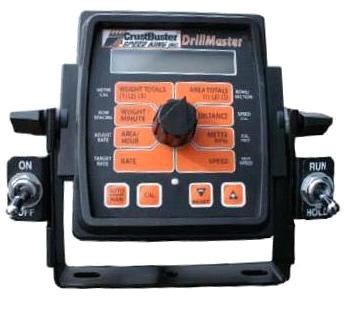
3 Description of Operation The DrillMaster is designed to drive a Proportional Flow Control Valve using a PWM output. The valve controls the flow to 1 to 3 hydraulic motors so it can be used with 1 to 3 section planters. All motors are in series so they all rotate at the same speed and therefore they all apply the same amount of seed. Three toggle switches (top of Console) turn the sections off, bypassing a motor, so the RPM of the remaining motors do not change. The DrillMaster operates as a ground speed based controller using a speed sensor input (from 1 of the 3 sections) to maintain a target population of seed as ground speed varies. An external Module is used to multiplex the flow signal so a different section is used when a section is turned off. Going to Hold, turning all Sections Off, or zero speed will stop auto control and will also stop the PWM Valve drive if Auto Shut Off is turned on (enabled). All sections are automatically turned off if the speed goes to zero while in Auto mode. Seed flow is measured indirectly by measuring the seed drive shaft RPM instead of counting seed. Drill Master also provides an early warning when seed bins are nearly empty by flashing a FILL message. Care and Maintenance of your DrillMaster Store the console in a cool dry location if it will not be used for an extended period of time, such as during the off-season. As with any electronic equipment, use care in cleaning so that water or other liquids do not enter the case. 1
4 Installation Mounting the Display Console Select a mounting location which seems most workable, and that best fits your needs. It should be convenient to reach and highly visible to the operator. DO NOT INSTALL IN A POSITION THAT OBSTRUCTS THE VIEW OF THE ROAD OR WORK AREA. Whenever possible, avoid locations that expose the console to direct sunlight, high temperature, strong chemicals or rain. Place the mounting bracket in selected location, mark hole, drill ¼ (7mm) holes and mount bracket with bolts, lockwashers and nuts provided. (Use selftapping screws if not practical to use bolts.) See Illustration 1A. Put rubber washers on carriage bolts and put the bolts through the bracket holes from the inside out. Loosely attach the mount knobs onto the bolts. Place console over carriage bolt heads and tighten knobs to secure the console. See Illustration 1B. Attaching the Power and Run/Hold Control Switches Mounting the Run/Hold Switch Kit Remove the mount knob from either side of the console. Install the bracket over the carriage bolt and along side the console bracket. Install the mount knob on the carriage bolt and tighten to secure the console and run/hold switch bracket in place. Install the switch into the bracket using the steps below: 1. Place the small washer on the switch followed by the flat notched washer. See Illustration Secure the washers in place with one of the hex nuts. 3. Peel the back from the decal and secure to the front of the switch bracket. See Illustration Install the switch in the bracket and secure in place with the remaining hex nut. NOTE: Make sure the ON connector is at the top. 5. Attach the quick disconnects on the switch harness to the switch. The RED wire should attach to the top connection with the BLACK attaching to the bottom connection. 6. Install the switch harness connector into the mating connector (gray tie) on the console harness. NOTE: If using the included Power On/Off switch instead of the ignition switch connection, install the power switch as described above. Connect the power switch cable connector (2 pin) to the mating connector on the console harness. 2

5 Installation (continued) Electrical Installation This section explains how to connect your DrillMaster to a 12-volt power source. NOTE: The DrillMaster must be connected to a 12 volt DC negative ground electrical system. POWER/BATTERY CONNECTION Locate the power cable for the DrillMaster and route to the battery. When routing cable to console, avoid areas where the cable may be subjected to abrasion or excessive heat. Attach the BLUE wire (ground) to a screw or bolt on the equipment frame. See illustration 3. Be sure there is a good metal-to-metal contact. Connect the ORANGE wire to the positive battery terminal. Connect the power to the DrillMaster console by plugging the 2-pin W/P tower on the power cable into the 2-pin W/P shroud of the display console. ON/OFF SWITCH CONNECTION The DrillMaster system uses P/N power switch to turn the system on. If the P/N power switch is used, simply mount the switch bracket as shown on page 4, and plug the connector into the mating cable from the console. Attaching the Speed Sensor The DrillMaster uses an Astro 5 GPS Speed Sensor. The speed sensor always connects to the 3-pin M/P connector with the yellow tie (on the back of DrillMaster). Speed calibration entered into the controller must be
6 DrillMaster Tractor Controller Wiring Layout 4

. WEIGHT / MINUTE: Displays 1000's of seed dispensed per minute.")
7 DrillMaster Console Functions The DrillMaster features a large, easy-to-read liquid crystal display, easy-to-use rotary dial and lighted panel for night use. SECTION ON/OFF: The Console has three Section ON/OFF toggle switches on top of the console. The toggle switches turn planter sections on and off directly and also signal the Console which sections are on or off. WEIGHT TOTALS (1) (2) (3): Displays total seed applied. May be reset. NOTE: WEIGHT and AREA counters work in pairs, if WEIGHT counter 1 is reset, it also resets AREA counter 1). WEIGHT / MINUTE: Displays 1000's of seed dispensed per minute. AREA / HOUR: Displays calculated Acres/Hour. RATE: Displays application rate in 1000's of seed / acre. AREA TOTALS (1) (2) (3): Keeps a running count of the total acres worked. May be reset. NOTE: WEIGHT and AREA counter work in pairs, if WEIGHT counter 1 is reset, it also resets AREA counter 1). DISTANCE: Displays distance traveled in feet. May be reset. METER RPM: Displays Seed Drive Shaft RPM. SPEED: Displays ground speed in miles per hour. WARNING LIGHT: Indicates over or under application of 10% of the Target Rate in AUTO or Loss of Sensor Signal in Man. Also lit when in CAL. 5
8 Singulated Seed Planting with the DrillMaster The DrillMaster will also control the planting of singulated seeds. The target rate will be the seed population, displayed in thousands of seeds per acre. The Meter Cal is specific to the cells on a seed disc and will not change. DrillMaster Controller Calibration for singulated seed meters: 1. Turn all section switches off and put system in hold. 2. Press CAL for one (1) second to enter calibration mode. Red light will be on steady and CAL will be displayed in CAL mode. NOTE: You cannot enter CAL without RUN/HOLD switch in hold. 3. Turn the dial to the items listed below and set as instructed. Numbers can be changed by using the + or - buttons. 4. When complete, press CAL for one (1) second to exit CAL mode. Red light should go out and CAL will not be displayed. You MUST exit Calibration mode to save your setting. METER CAL: Enter the Meter Cal for the seed meter you are using from the chart below. Number of seed cells in seed meter Meter Cal in DrillMaster Formula: Meter Cal = 60 pulses a revolution number of seed cells x 1000 ROW SPACING: Enter the AVERAGE row spacing in inches of your implement. For example, on a 38" twin row planter, you would enter the average row spacing of 19". ADJUST RATE: Enter the value for the disired amount of change in thousand seeds/acre to be used for making on the go rate adjustments. TARGET RATE: Enter the desired planting rate in thousand seeds/acre. ROWS/SECTION: Enter the # of SEED METERS per section. For a twin row configuration, each twin row has 2 seed meters. This displays the rows per section for the section selected. Unused sections must be programmed to zero rows. sections. The DrillMaster can have up to three NOTE: The controller must be out of HOLD and be in RUN to enter rows/section. Turn section one on while the other two sections are off. The corresponding section icon 1 will turn on and the number of rows in the section can then be adjusted. After section one is entered, turn it off and turn section two on, then turn two off and turn the section 3 on and adjust. When finished, turn the DrillMaster back to hold and the screen will display no SECtn. If you are on a single or two section planter, the sections not being used must be set to 0 rows. SPEED CAL: For the ASTRO 5 which is included with the DrillMaster, this setting should be.189. CAL TEST: This is not a true Calibration Factor but rather a method of testing the planter to confirm the seed meter dispenses the correct number of seeds. Prior to using CAL TEST for singulated seeds, it is recommended to change the sample size that will be dispensed. After exiting the CAL mode, and red light is off. 1. Turn DrillMaster Off 2. Hold down AUTO/MAN and CAL buttons while turning DrillMaster on. Spec will show on disp;ay briefly. 3. Push CAL until 1" shows in display. 4. Turn dial to DISTANCE/SPEED CAL position. 5. Default value is 1.00, which will dispense 1,000 seeds per meter. We recommend you change this value to 0.150, which will dispense 150 seeds/meter. 6. Push CAL until red light goes off and CAL is not shown on the display. TEST SPEED: This is also not a true Calibration Factor. TEST SPEED along with CAL TEST will be used in the Pre- Planting Seed Calibration Process. 6
9 Pre-Season Test This test should be done prior to every planting season. You will have to have the implement hooked to tractor with hydraulics available. The tractor will remain stationary. 1. This test should be done after completing the INITIAL SETUP on page Turn power toggle to ON position, and RUN/HOLD toggle to HOLD. 3. Enter CAL mode by pushing and holding CAL soft key until red warning light is steady on. 4. Turn center rotary switch to TEST SPEED. Use + or - soft key to adjust speed you plan to run in the field. (Example: 5.0 mph) 5. Turn hydraulics on. NOTE: There is a check valve on the hydraulic hoses which prevents the motors from running backwards. However, on initial start up they may momentarily run backwards. 6. Push AUTO/MAN soft key so AUTO is displayed on screen. 7. Make sure all necessary Section toggles are in the ON position. 9. Now that motors are running, put center rotary switch on METER RPM and you should have a rpm reading on the display. Shut off Section toggle switches one by one and you should continue to get a rpm reading until the last section is shut off. This verifies that all shaft sensors and poppet valves on motors are working. 10. With everything still running, turn all Section toggles ON that are being used. Switch to HOLD. 11. Push and hold CAL to get out of calibration. 12. Push AUTO/MAN button to enter manual mode. 13. Move center rotary selector to RATE. 14. Switch RUN/HOLD toggle to RUN. 15. Push and hold + soft key. Hydraulic motors should speed up to maximum speed. 16. Push and hold - soft key. Hydraulic motors slow down to almost a stop. 17. This verifies the PWM valve is working properly. 8. Put RUN/HOLD switch to RUN. Lower planter to activate mercury switch. Hydraulic motors should now be running; if not, make sure hydraulics is selected in correct direction and Section switches are on. 7
10 Singulated Seed Planting with the DrillMaster Seed Meter Test Process (Using CAL TEST function) This procedure is used prior to field operation. These steps will verify the DrillMaster and your seed meter dispenses the correct number of seeds. Preparation 1. Fill planter with enough seed to fill meter. 2. Position catch container under each seed tube. Enter Calibration Mode (switch controller to hold and press the CAL button until the red light is solid). 1. Turn Rotary Position Switch to Cal Test, Off appears in the display, press + to activate the Calibration Test mode..150 appears in the display to dispense a 150 seed sample. To set sample size, see singulated seed calibration. 2. Turn rotary position switch to Test Speed. 3. Use + to enter normal operating speed. 4. Turn rotary position switch back to Cal Test. 5. Switch from the hold to the run position and turn all sections on. The Cal Test will begin. The display will count up the measured sample size and automatically turn off at 150 seeds. 6. Count the seeds to verify proper operation and calibration. 7. Press and hold CAL until red light is off to exit calibration. If the proper number of seeds is not dispensed: 1. Check Meter Cal. 2. Is the meter drive shaft speed sensor properly aimed at 60 tooth target (1/16-1/8" clearance). 3. Is meter and vacuum level adjusted properly. In-Field Operation in AUTO Mode 1. Switch on tractor hydraulics. 2. Turn on all Section switches located on the top of the DrillMaster controller. 3. Push AUTO/MAN button until AUTO is displayed on DrillMaster display screen. 4. Switch RUN/HOLD toggle switch to RUN. 5. DrillMaster controller and planter hydraulic drive should now be ready for AUTO field operation. Planter should now operate only when planter is down and tractor is moving. 8
11 Single Section System Diagram 9
12 Multi-Section System Diagram 10
13 DrillMaster Wiring Diagram Single Section 11
14 DrillMaster Wiring Diagram Multi Section 12
15 SPEED CAL Numbers for various radar models or GPS speed sensors Radars Cal No. Hz / MPH Vansco Raven Magnavox Dickey-John Dickey-John Dickey-John Dickey-John GPS Speed Cal No. Hz / MPH Astro SkyTrak (Std) SkyTrak (MT) Dickey-John John Deere ³ Shipped with DrillMaster Part No. Description Bin Level Kit ASTRO V GPS Speed Sensor Multiplexer Module, Multiple Section Gear Tooth Sensor, CHERRY PWM Hydraulic Control Valve ' Extension Cable, 10 Pin Mercury Switch, Implement Mounted RUN/HOLD Hydraulic Motor with Shut Off, 4.9 CID, CCW Mounted Drill Kit Single Section Drill Kit #40 Sprocket 14 Tooth #40 Sprocket 30 Tooth #2050 Sprocket 20 Tooth #2050 Sprocket 30 Tooth Hydraulic Check Valve SAE Tooth Adjustment Handle 13
16 Hydraulic Circuit 14

17 Determining Hydraulic Motor Rotation Motor rotation must turn the seed shaft of the planter counter-clockwise when viewed from the left end of the planter Motor rotation is determined by looking into the shaft end of the motor. For counter-clockwise rotation oil should flow into port marked 2, out port 1, into the next motor in the series or back to the bypass port tee fitting on the PWM valve. The ON-OFF solenoid valve must be mounted in the cavity next to the in port. Reverse ports and solenoid valve for clock-wise rotation. Photo show motor configured for counter-clockwise rotation. 15


18 Tractor Hydraulic Requirements The hydraulic drive motors require a maximum of 7 gallon per minute of hydraulic oil at a maximum pressure of 1500 psi. Average oil requirement is usually less then 5 gallon per minute. With minor modification the drive PWM valve will function with a tractor equipped with a closed or open center hydraulic system. Contact your tractor dealer to determine which hydraulic system your tractor may have. Most recently manufactured tractors are equipped with a closed center hydraulic system. The PWM valve is shipped with the closed center cavity plug installed. Tractors with open center system: 1. When running in series with another hydraulic motor, such as a planter fan motor. The SureFire valve must allow all oil going through the fan to pass through it. The SureFire valve will be open center and divert the necessary oil to the SureFire hydraulic motor. 2. When running in series with two SureFire valve/motor combinations. This might happen in the case of two seed drives or two pumps. Each valve needs to let excess oil pass through so the second valve has plenty of oil to accomplish its necessary task. Tractors with closed center system: 1. When running this valve by itself from a tractor hydraulic remote. By running closed center, the SureFire valve will use the minimum amount of oil and cause the least oil circulation and heating. This leaves the most oil for other hydraulic functions. 2. When running off power beyond hydraulic ports, the valve must be closed. Install this #10 MB plug to run open center. Valve will allow all oil to pass through it, then divert necessary oil to the hydraulic motor. Install this cavity plug to run closed center. Valve will allow all oil motor needs to pass through. 16
19
20 P.O.Box 1438 Dodge City, Kansas (620)
DrillMaster. Grain Drill Section Controller REFERENCE MANUAL /10
 DrillMaster Grain Drill Section Controller REFERENCE MANUAL 611327-11/10 TABLE OF CONTENTS Description of Operation, Safety and Care...3 Installation...4 Console Functions...7 Calibration...8 Operation...13
FORCE UNLTD. SPREADERS*GPS EQUIPMENT*CONVEYORS
 FORCE UNLTD. SPREADERS*GPS EQUIPMENT*CONVEYORS SAFETY INFORMATION PAGE NO. Signal Word Definitions 0.1 OPERATING INSTRUCTIONS PAGE NO. 24" & 30" Spinner Disc Location 1.1 Fin Location 1.2 Conveyor Speed
Quick Setup Guide for IntelliAg Model YP Air Pro
 STEP 1: Pre-Programming Preparation: The Quick Guide assumes the Virtual Terminal, Master Switch, Working Set Master, Working Set Member, and all sensors have been connected and properly installed. Reference
Y1. Troubleshooting / Service Guide for SureFire PWM Liquid Application Systems. SureFire Commander II Controller
 396-3265Y1 Troubleshooting / Service Guide for SureFire PWM Liquid Application Systems SureFire Commander II Controller Always verify the controller settings. See the screenshots in Section F of the system
FORCE UNLTD. SPREADERS*GPS EQUIPMENT*CONVEYORS
 FORCE UNLTD. SPREADERS*GPS EQUIPMENT*CONVEYORS SAFETY INFORMATION PAGE NO. Signal Word Definitions 0.1 OPERATING INSTRUCTIONS PAGE NO. 24" & 30" Spinner Disc Location 1.1 Fin Location 1.2 Conveyor Speed
Quick Setup Guide for IntelliAg Model YP40 20 Air Pro
 STEP 1: Pre-Programming Preparation: The Quick Guide assumes the Virtual Terminal, Master Switch, Working Set Master, Working Set Member, and all sensors have been connected and properly installed. Reference
Technical Training GEN I
 Technical Training GEN I Air Flow & Hose Routing The centerline of the goose neck arms hitch point (center of balls or knuckle hitch bolts) to the furthest back part of the row unit or bar attachment can
RAM Rail Mount Kit RAM 201UD 5 Arm RAM 2461U Base RAM 235U Base, Double U-Bolt
 Note: Indented items indicate parts included in an assembly listed above. Part Name/Description Part Number Quantity Direct Command Kit 4100514 1 Installation Instructions 2005690 1 CAN Y-Splice 4000137
Quick Setup Guide for IntelliAg Model YP Twin Row
 STEP 1: Pre-Programming Preparation: The Quick Guide assumes the Virtual Terminal, Master Switch, Wking Set Master, Wking Set Member, and all senss have been connected and properly installed. Reference
Sprayer Control. Manual for SprayLink Cable Installations. Tank. Jet Agitator. Agitator Valve. Diaphragm Pump. Pressure Transducer.
 Sprayer Control Plumbing & Installation Manual for SprayLink Cable Installations Tank Jet Tank Shut-Off Diaphragm Pump Electric Ball s Transducer Strainer Relief Regulating Copyrights 2012 TeeJet Technologies.
Quick Setup Guide for IntelliAg Model YP
 STEP 1: Pre-Programming Preparation: Power on vehicle via ignition switch to activate Virtual Terminal (VT). Main menu will display pre-programmed default settings. If errs are detected (e.g., failed senss,
Quick Setup Guide for IntelliAg Model 3PYP 12 Row Single Row Air Pro
 STEP 1: Pre-Programming Preparation: Power on vehicle via ignition switch to activate Virtual Terminal (VT). Main menu will display pre-programmed default settings. If errors are detected (e.g., failed
FORCE Unltd. FLOATER CHASSIS INSTRUCTIONS 4/1/09
 FORCE Unltd. FLOATER CHASSIS INSTRUCTIONS 4/1/09 TORQUEING THE BOLTS ABOVE THEIR RATING WILL FAIL THE BOLT - --DON T OVER TORQUE THE BOLTS AXLE U-BOLT TORQUE (IMPORTANT) CHECK THE SIZE OF THE U-BOLT FRONT
SureFire Drives and Harnesses for use with John Deere Dry Rate Controller
 396-001640 SureFire Drives and Harnesses for use with John Deere Dry Rate Controller & SureFire Dry Fertilizer Control Components 396-001640 John Deere Rate Controller Dry Instructions Page 1 02/23/2012
Maximum Application Rates with Two 5.3 GPM Electric Pumps
 396-001450 Tower Electric Pump Fertilizer System and SureFire Commander II Maximum Application Rates with Two 5.3 GPM Electric Pumps Maximum Application Rates in GPA on 30" Rows at 6 MPH (no agitation)
Standard Version REFERENCE MANUAL
 R o a d M a s t e r TM Standard Version REFERENCE MANUAL R o a d M a s t e r TM Standard Version reference MANUAL The RoadMaster is an electronic control system that can help you operate more cost-effectively
Instructions for Micro-Trak Seed Rate Control Systems Used with AgLeader INSIGHT, INTEGRA One, Two and Three Section
 1. Use AgLeader System Diagrams and Operator Manual to install system components and harnessing. 2. Connect Hydraulic Seed Control Module to the planter drives (as shown below) using Micro-Trak P/N 18030
Clutch Control. PN: November 2013 Rev E 1
 NOTE: Indented items indicate parts included in an assembly listed above Part Name/Description Part Number Quantity Module Kit 4100533 1 Cable Installation Kit 2000901-1 1 Alcohol swab packet 2002811 2
& Tower for PWM Control. Maximum Application Rates with Two 5.3 GPM Electric Pumps
 396-001060 Tower Electric Pump Fertilizer System for John Deere GS2 2600 & GS3 2630 & Tower for PWM Control Maximum Application Rates with Two 5.3 GPM Electric Pumps Maximum Application Rates in GPA on
CONTENTS 1.0 INTRODUCTION SAFETY... 5
 Contents CONTENTS 1.0 INTRODUCTION........................... 3 2.0 SAFETY.................................. 5 3.0 SETUP................................... 7 AccuShot System Screen ICON Description.....
Field-IQ & PumpRight for PWM Control. Pump Models & Flow Capability. Max Flow GPM
 PumpRight Fertilizer System for Trimble Field-IQ (FmX or FM-1000 Displays) Field-IQ & PumpRight for PWM Control Number of Diaphragms 396-001230 Pump Models & Flow Capability Max Flow GPM Max GPA on 40
Seed Rate Charts for the YP1225 or YP1625 Planters
 Manufacturing, Inc. www.greatplainsmfg.com Seed Rate Charts for the YP1225 or YP1625 Planters For Yield-Pro 1225 s/n A1056K to A1110K For Yield-Pro 1625 s/n A1104B to A1189B The following pages are to
& PumpRight for PWM Control. Maximum Pump Flow and Application Rates. Max Flow GPM
 396-001070 PumpRight Fertilizer System for John Deere GS2 2600 & GS3 2630 & PumpRight for PWM Control Maximum Pump Flow and Application Rates Number of Diaphragms Max Flow GPM Max GPA on 40 at 6 MPH Max
Endeavor Fertilizer Controler" Electric Pump Fertilizer System for John Deere GS2 with Servo Control
 Endeavor Fertilizer Controler" Electric Pump Fertilizer System for John Deere GS with Servo Control We Can Also Interface with These Popular Third Party Controllers: Trimble - EZ Boom & Field IQ Ag Leader
Population pre-def ned Every Row Population. For other pre-def ned are made to the system or if options are added to the base planter.
 The Quick Guide assumes the Virtual Terminal, Master Switch, Working Set Master, Working Set Member, and all sensors have been connected and properly installed. Reference Operar s manual for installation
Y1 Tower Electric Pump Fertilizer System for John Deere Rate Controller 2000 (JDRC 2000)
") 396-3616Y1 Sy st em s Tower Electric Pump Fertilizer System for John Deere Rate Controller 2000 (JDRC 2000) Su re Fi re Ag & Tower for PWM Control Maximum Application Rates with Two 5.3 GPM Electric Pumps
396-3616Y1 Sy st em s Tower Electric Pump Fertilizer System for John Deere Rate Controller 2000 (JDRC 2000) Su re Fi re Ag & Tower for PWM Control Maximum Application Rates with Two 5.3 GPM Electric Pumps
DeltaForce System Operation
 DeltaForce System Operation 955294 1 1/2014 Index Precision Planting Warranty and Liability.Page 3 Safety Information Page 4 System Requirements.Page 5 Frequently Asked Questions..Page 6 Hydraulic Fittings..Page
& PumpRight for PWM Control. Pump Models & Flow Capability. Max Flow GPM
 PumpRight Fertilizer System for AFS Pro 700 And Planter ECU & PumpRight for PWM Control Number of Diaphragms 396-3292Y1 AFS Pro 700 and Planter ECU Pump Models & Flow Capability Max Flow GPM Max GPA on
OPERATOR S MANUAL DO NOT USE OR OPERATE THIS EQUIPMENT UNTIL THIS MANUAL HAS BEEN READ AND THOROUGHLY UNDERSTOOD. PART NUMBER Rev.
 8150 OPERATOR S MANUAL DO NOT USE OR OPERATE THIS EQUIPMENT UNTIL THIS MANUAL HAS BEEN READ AND THOROUGHLY UNDERSTOOD PART NUMBER 393-000-015 Rev. C Table of Contents 1 TABLE OF TITLE CONTENTS 393-000-015
Manufacturing, Inc.
 Table of Contents Metric Charts Manufacturing, Inc. www.greatplainsmfg.com Seed and Fertilizer Rate Charts for 2009+ Yield-Pro Planter Models YP1225 s/n A1111K+ YP1625 s/n A1190B+ The following pages are
Planting. Press to Highlight Configuration. Gauge Wheel Load Alarm. Value must be entered for your specific planter and parallel arm combination
 To create a configuration, make the following button presses to start the Configuration Wizard and then follow the instructions given on the display. Planting Start of Configuration Wizard Enter Settings
Troubleshooting a Planter that applies above or below target rate
 Troubleshooting a Planter that applies above or below target rate The purpose of this document is to provide troubleshooting steps to solve complaints of a planter applying above or below the target rate.
MODEL MCL /8 SPEEDOMETER/TACHOMETER for 2004 up
 MODEL MCL-3204 3-3/8 SPEEDOMETER/TACHOMETER for 2004 up IMPORTANT NOTE! This gauge has an odometer preset option that is only available one time in the first 100 miles (160km) of operation. See Odometer
OPERATOR S MANUAL DO NOT USE OR OPERATE THIS EQUIPMENT UNTIL THIS MANUAL HAS BEEN READ AND THOROUGHLY UNDERSTOOD. PART NUMBER Rev.
 8160 OPERATOR S MANUAL DO NOT USE OR OPERATE THIS EQUIPMENT UNTIL THIS MANUAL HAS BEEN READ AND THOROUGHLY UNDERSTOOD PART NUMBER 39300030 Rev. E Table of Contents 1 TABLE OF TITLE CONTENTS 39300030 Rev.
General Information. Veris Drive Option
 No-Till and No-Till Precision Seeding System Used with: 3N-3010P and 3N-3020P 3N-3010 and 3N-3020! When you see this symbol, the subsequent instructions and warnings are serious - follow without exception.
KPM III ELECTRONIC SEED MONITOR INSTALLATION INSTRUCTIONS
 KPM III ELECTRONIC SEED MONITOR INSTALLATION INSTRUCTIONS Rev. 9/07 Throughout these instructions the symbol and/or the words NOTE, IMPORTANT, CAUTION, WARNING or DANGER are used to call your attention
CONTROL BOX. Wiring the control box into the vehicle. +12V
 CONTROL BOX Once the display panel is in place, mount the control box within the connecting cable's distance (approximately 3 feet) and secure to the underside of the dashboard. This case does not have
HLY-3015 MINI SPEED/TACH INFORMATION SYSTEM (weather and vibration resistant for exposed environments)
") HLY-3015 MINI SPEED/TACH INFORMATION SYSTEM (weather and vibration resistant for exposed environments) Neutral Left turn Low voltage Right turn High beam Engine Low oil *To avoid damage to motorcycle,
HLY-3015 MINI SPEED/TACH INFORMATION SYSTEM (weather and vibration resistant for exposed environments) Neutral Left turn Low voltage Right turn High beam Engine Low oil *To avoid damage to motorcycle,
Electronic Dynamo Regulator INSTRUCTION MANUAL. COPYRIGHT 2014 CLOVER SYSTEMS All Rights Reserved
 DRM TM DRM-HP TM Electronic Dynamo Regulator INSTRUCTION MANUAL COPYRIGHT 2014 CLOVER SYSTEMS All Rights Reserved INTRODUCTION The Clover Systems DRM is a state-of-the art all-electronic voltage and current
Operator s Manual 09PDMS (100 Lb.) & P45PDMS (45 Lb.) Poly Stainless MP +3 (Positive Displacement Metering System)
 & P45PDMS (45 Lb.) Poly Stainless MP +3 (Positive Displacement Metering System)") Operator s Manual 09PDMS (100 Lb.) & P45PDMS (45 Lb.) Poly Stainless MP +3 (Positive Displacement Metering System) Anertec & Gandy Company 815 Rice Lake Street Owatonna, MN 55060 Telephone: 507-451-5430
Operator s Manual 09PDMS (100 Lb.) & P45PDMS (45 Lb.) Poly Stainless MP +3 (Positive Displacement Metering System) Anertec & Gandy Company 815 Rice Lake Street Owatonna, MN 55060 Telephone: 507-451-5430
DrVanos.com Stage II Installation Instructions. Tool rental is available with the purchase of a vanos kit *See website for more info*
 DrVanos.com Stage II Installation Instructions Special Tools Needed: Camshaft locking tool TDC Crank pin Sprocket turning tool Tool rental is available with the purchase of a vanos kit *See website for
FORM # PRINTED IN U.S.A. PAGE 1 OF 11
 FORM #33002.08-010507 PRINTED IN U.S.A. PAGE 1 OF 11 SUPERLIFT SUSPENSION SYSTEMS 300 Huey Lenard Loop Rd. West Monroe, Louisiana 71292 Phone: (318) 397-3000 Sales / Tech: 1-800-551-4955 FAX: (318) 397-3040
AgXcel GX5 Install Guide for Integration into Trimble. where precision meets the soil... PO Box 1611 Kearney, NE
 where precision meets the soil... AgXcel GX5 Install Guide for Integration into Trimble PO Box 1611 Kearney, NE 68848 877.218.1981 www.agxcel.com where precision meets the soil... AgXcel Integration into
TASC-6100 LIQUID/GRANULAR APPLICATION CONTROL SYSTEM USER GUIDE PN R2 Software Version 1.30
 Alt.-Rate Standard Rate OFF MIDWEST TECHNOLOGIES, INC. TASC-6100 LIQUID/GRANULAR APPLICATION CONTROL SYSTEM USER GUIDE PN - Software Version 1.30 MPH MID-TECH ON OPERATE INC. OFF SET- UP DEC. %Rate Product
Seed-Squirter. Installation Guide. APPLICATION SYSTEMS FOR PROFESSIONALS. How Can We Help?
 Installation Guide APPLICATION SYSTEMS FOR PROFESSIONALS TM www.capstanag.com How Can We Help? 855-628-7722 prodsupport@capstanag.com P/N 115700-007 Rev. A Revised 02/2018 2018 Capstan Ag Systems, Inc.
Table of Contents. General Operation. 3 How Slam-A-Winner plays How the Wheel Scores How the Ball Lift works Programming Options...
 61-MAN-B Table of Contents General Operation. 3 How Slam-A-Winner plays How the Wheel Scores How the Ball Lift works Programming Options... 4-6 Troubleshooting Guide. 7-8 Parts Identification 9 Schematics
Instructions for 2-row monitoring only
 Installation Instructions for CaseIH cotton picker models: Instructions for 2-row monitoring only Ensure the model numbers shown above correspond to the machine model. If you receive the incorrect installation
CONTROL SYSTEMS FOR PRECISION FARMING. IntelliAg puts the future of application control in your cab providing state-ofthe-art
 CONTROL SYSTEMS FOR PRECISION FARMING IntelliAg puts the future of application control in your cab providing state-ofthe-art communication between implement and tractor. INTELLIAG CONTROL SYSTEMS Compatible
 Special Tools Needed: DrVanos.com Stage I Installation Instructions Camshaft locking tool TDC Crank pin Sprocket turning tool Tool rental is available with the purchase of a vanos kit *See website for
Instructions for 2-row monitoring only
 Installation Instructions for CaseIH cotton picker models: Instructions for 2-row monitoring only CAUTION: Ensure the model numbers shown above correspond to the machine model. If you receive the incorrect
Seed and Fertilizer Rate Charts for the YP3025A, YP4025A and YP4425A 30, 40 and 44-Foot 3-Section Yield-Pro Planters with Air-Pro seed meters
 Table of Contents Metric Charts Manufacturing, Inc. www.greatplainsmfg.com Seed and Fertilizer Rate Charts for the YP3025A, YP4025A and YP4425A 30, 40 and 44-Foot 3-Section Yield-Pro Planters with Air-Pro
MODEL MCL-3212 SPEEDOMETER/TACHOMETER for 2012 up Dyna and Softail with 4 gauge
 MODEL MCL-3212 SPEEDOMETER/TACHOMETER for 2012 up Dyna and Softail with 4 gauge IMPORTANT NOTE! This gauge has an odometer preset option that is only available one time in the first 100 miles (160km) of
400 INSTALLATION & OPERATION INSTRUCTIONS
 Primo 400 Primo 400 Primo 400 INSTALLATION & OPERATION INSTRUCTIONS PART No: AM PrimoV2 Primo 400 Contents Page 1 Contents 1.0 Introduction...3 1.1 General Outline... 3 2.0 Installation...4 2.1 Controller
2-row and All-row systems included.
 Ag Leader Technology Cotton Picker Installation Installation Instructions for John Deere cotton picker models: 2-row and All-row systems included. IMPORTANT: Ensure the model numbers shown above correspond
Freeman 380/385 Hydro PTO Operator Controls and Baler Connection Instructions
 Freeman 380/385 Hydro PTO Operator Controls and Baler Connection Instructions The following pages detail how to connect and use the controls on your Hydro PTO Baler. Please consult Operators manual PB00000102
SAC Liquid Manure Flow Meter
 LM300000 REV A 11/11/2009 QUALITY PEOPLE, QUALITY PRODUCTS SAC Liquid Manure Flow Meter Operation and Service Manual ASSEMBLY CALIBRATION OPERATION REPLACEMENT PARTS READ complete manual CAREFULLY BEFORE
Full screen alarms identify abnormal or failed operation on all enabled system components/controls
 The world s most versatile controller IntelliAg puts the future of application control in your cab, providing state-of-the-art communication between implement and tractor. This precision farming system
CS 420RC. Solid De-icer Controller Configuration and Set-up Manual
 CS 420RC Solid De-icer Controller Configuration and Set-up Manual 2/15 Table of Contents 1 Systems Modes of Operation 3 2 System Features 4 3 System Description 5 4 System Specifications 6 4.1 CS-420RC
Hot Tach Pro Operation Manual. Competition Systems, Inc Vista Terrace Lake Forest, CA (949)
") Hot Tach Pro Operation Manual Competition Systems, Inc. 26806 Vista Terrace Lake Forest, CA 92630 (949) 580-6898 Hot Tach Pro Operation Manual Revsion:4/2000 Hot Tach Pro Operation Manual Revsion:4/2000
Hot Tach Pro Operation Manual Competition Systems, Inc. 26806 Vista Terrace Lake Forest, CA 92630 (949) 580-6898 Hot Tach Pro Operation Manual Revsion:4/2000 Hot Tach Pro Operation Manual Revsion:4/2000
RateKing Plus Automatic Rate Controller System Manual
 RateKing Plus Automatic Rate Controller System Manual System Manual RateKing Plus Automatic Rate Controller The RateKing Plus is an electronic control system that can help you achieve maximum yields and
ADJUSTMENTS BEFORE GOING TO THE FIELD
 FIELD ADJUSTMENTS YIELD-PRO PLANTER 4010HDP, 4020P, 4025 3010HDP, 3020P, 3025 ADJUSTMENTS BEFORE GOING TO THE FIELD General Maintenance: 1). Refer to the operator s manual for proper lubrication intervals
Full Sweep Minor Gauge Wiring:
 Full Sweep Minor Gauge Wiring: Notes on Senders: Temp Hi match/vdo 150C: Normally used in Oil temp, 140 280F. Temp Low match/vdo120c: Normally used in water temp, 100 240F. To test the gauges work (oil,
MODEL MCL-2002 TANK MOUNT SPEEDOMETER/TACHOMETER
 MODEL MCL-2002 TANK MOUNT SPEEDOMETER/TACHOMETER *To avoid damage to motorcycle, please see Speedometer, Tachometer, and Status and Warning Indicators sections for details on locating VSS, Tachometer,
THIS MANUAL DESCRIBES THE SMARTCRAFT GAUGE SYSTEMS AVAILABLE FOR YOUR BOAT
 Systems Monitor Operation Manual THIS MANUAL DESCRIBES THE SMARTCRAFT GAUGE SYSTEMS AVAILABLE FOR YOUR BOAT 2004, Mercury Marine 90-895202 204 0 TABLE OF CONTENTS Legend..............................................
Sync-Row for MONOSEM Twin-Row. Setting the Twin-Row Stagger INSURE THESE VALUES ARE CORRECT FOR YOUR TWIN ROW PLANTER
 Sync-Row for MONOSEM Twin-Row TIMING CHART 30" ROW SPACING Chart for Adjustable Metering Sprocket INSURE THESE VALUES ARE CORRECT FOR YOUR TWIN ROW PLANTER Crop Corn Number of Seed Disk Cells (holes) 18
Installation and Operation Instructions
 Installation and Operation Instructions Electronic Boost Controller (Rev. F1) Contents list: Before installation of your Boondocker Electronic Boost Controller (EBC), check the contents of your kit. Find
834 Sprayer Control L2.12 User Guide R1
 834 Sprayer Control L2.12 User Guide 98-70019-R1 TECHNOLOGES Table of Contents 834 Sprayer Control Programming Guidelines 3 Start 4 System Setup Mode 5 ensity 5 Speed Sensor Calibration 6 Auto Calibration
Rostselmash Torum 740
 Note: Indented items indicate parts included in an assembly listed above Quantity by Model Part Name/Description Part Number 740 Combine Kit Torum 740 4100762 1 Threaded Arm Assembly 2000311-2 1 Header
HLY-3016 PERFORMANCE SPEEDOMETER/TACHOMETER COMBO (weather and vibration resistant for exposed environments)
") HLY-3016 PERFORMANCE SPEEDOMETER/TACHOMETER COMBO (weather and vibration resistant for exposed environments) *To avoid damage to motorcycle, please see Speedometer, Tachometer, and Status and Warning Indicators
HLY-3016 PERFORMANCE SPEEDOMETER/TACHOMETER COMBO (weather and vibration resistant for exposed environments) *To avoid damage to motorcycle, please see Speedometer, Tachometer, and Status and Warning Indicators
MCL-30K-SPD IMPORTANT NOTE!
 MCL-30K-SPD Thank you for purchasing the Dakota Digital MCL-30K-SPD gauge for your Harley Davidson Touring bike. This is designed to be a replacement for all touring models from 1996 2003. This is part
ADJUSTMENTS BEFORE GOING TO THE FIELD
 FIELD ADJUSTMENTS YIELD-PRO PLANTER with Air Pro Meters 2425A ADJUSTMENTS BEFORE GOING TO THE FIELD General Maintenance: 1). Refer to the operator s manual for proper lubrication intervals and maintenance
CS 430RC. Solid De-icer Controller Configuration and Set-up Manual
 CS 430RC Solid De-icer Controller Configuration and Set-up Manual 2/17 Table of Contents 1 Systems Modes of Operation 3 2 System Features 4 3 System Description 5 4 System Specifications 6 4.1 CS-430RC
Setup for using our speedometer with GPS sensor
 Setup for using our speedometer with GPS sensor Wiring: Speedometer red (1) power +12V Speedometer black (5) - ground Speedometer green (4) LED illumination (can be 12V) Speedometer blue (7) signal input,
844-E Sprayer Control. Installation, Programming and Operating
 844-E Sprayer Control User MANUAL Installation, Programming and Operating Table of Contents Chapter 1 - introduction 1 Chapter 2 - Mounting Sprayer Components 2 Pressure Regulator in Bypass Mode... 2 Pressure
Part Name/Description Part Number Quantity Instruction Kit Metalfor Flow Sensor
 NOTE: Indented items indicate parts included in an assembly listed above Part Name/Description Part Number Quantity Instruction Kit Metalfor 4101091 1 Flow Sensor 4001356 1 Deflector plate 2000612-1 1
ROW PRO DOWN PRESSURE
 Operator s Manual ROW PRO DOWN PRESSURE VERSION 2 & 3 Safety Notices... 1 Disclaimer... 1 Row-Pro Down Pressure... 3 Requirements... 3 Setup... 4 Control Mode... 4 Disable Down Pressure Modules... 7 Setting
To Purchase This Item, Visit BMI Gaming
 Table of Contents General Operation. 3 How Slam-A-Winner plays How the Wheel Scores How the Ball Lift works Programming Options... 4-6 Troubleshooting Guide. 7-8 Parts Identification 9 Schematics 10-13
ALL PLANT & MIN TILL DRILL
 4000 SERIES ALL PLANT & MIN TILL DRILL OWNER S MANUAL ADDENDUM OPERATION MAINTENANCE REPAIR PARTS #608869 (03-08) 2 Table of Contents Precision Planting Metering System 5-9 Precision Planting Introduction
Automotive Application ET01 Software Revision A 12/06
 Automotive Application ET01 Software Revision A 12/06 INTRODUCTION... 2 FUNCTIONAL DESCRIPTION... 3 INSTALLATION... 4 COMPONENT PLACEMENT... 4 PLUMBING AND WIRING... 5 MSBC OPERATION (ET-01)... 14 TIMED
Rally computer 3 Rally computer 3.GPS *
 Rally computer 3 Rally computer 3.GPS * User manual. Installation and configuration instructions. (with links to video instructions online at : www.rallycomputer.com ) * Content marked applies only to
Section 35 Chapter 9
 Section 35 Chapter 9 HITCH SYSTEM How it Works 6-12820NH TABLE OF CONTENTS THREE POINT HITCH... 35-3 ELECTRONIC HITCH CONTROL... 35-4 ELECTRONIC HITCH CONTROL... 35-5 ELECTRONIC HITCH CONTROL SYSTEM FEATURES...
Aftermarket Interface Module
 An ISO 9001:2008 Registered Company Aftermarket Interface Module (2015-2018 Ford Transit) AIM514-B High Side Solenoid type Coolant Valve Control AIM515-B Motor Reversing type Coolant Valve Control Introduction
DirectMount EXHAUST BRAKES
 DirectMount EXHAUST BRAKES APPLICATION: Fixed Orifice and PRXB Exhaust Brakes 2003 2005 Dodge Trucks with 3.5" & 4" Exhaust and 47RE & 48RE Automatic Transmissions Only Vehicles with an existing air compressor
INSTALLATION GUIDE Chevrolet Digital Dash Panel Part Number: DP6003 Year Series:
 INSTALLATION GUIDE Chevrolet Digital Dash Panel Part Number: DP6003 Year Series: 1967-1972 * Disconnect the battery before attempting any electrical work on your vehicle. * KIT COMPONENTS One (1) Digital
744A SprAyer Control U S e r M A n U A l
 744A Sprayer Control User MANUAL Table of Contents Product Chapter 1 - Introduction 2 System Configurations... 2 Kit Contents... 4 Control Housing Assembly... 6 Chapter 2 - Installation 7 Mounting Bracket...
AutoSteer Installation Guide
 AutoSteer Installation Guide John Deere JD-9860 STS Combine Harvester Covers AutoSteer (IK#180-0051-01 Rev A) installation on the following combine models having single cylinder rear axle: JD-9650 STS
HORTICULTURE EQUIPMENT & SERVICES
 HORTICULTURE EQUIPMENT & SERVICES OPERATOR S MANUAL PEAT BALE PROCESSOR Model Number: LH00 Serial Number: 30000 & UP Contents Introduction Page Safety Safety 2 Safety Decal Instructions 2 Specifications
HL515-B Fast Idle, Lift Interlock Ford Transit
 An ISO 9001:2008 Registered Company HL515-B Fast Idle, Lift Interlock 2015-2018 Ford Transit Introduction The HighLock 515-B is a wheelchair lift safety interlock which will only work with the ignition
FOR New Electric Kit and Remote Control Installation
 Installation Manual COMMAND-10 REMOTE AND COMMAND STATION FOR New Electric Kit and Remote Control Installation Use these in place of the rocker switch and solenoid section of instructions in your roll
Installation Instructions ISOBUS Liquid ECU
 Installation Instructions ISOBUS Liquid ECU Liquid Fertilizer & Ammonia Display Screen Sprayer Display Screen Last Update: 3/1/2018 SW Version Liquid v.01.00.04.00 - ECU HW: 1.6-1.7 SW Version Liquid v.02.00.01.00
PIM701 (Police Interface Module) Dodge Charger Pursuit
 Dodge Charger Pursuit") An ISO 9001:2008 Registered Company PIM701 (Police Interface Module) 2015-2017 Dodge Charger Pursuit Introduction The Police Interface Module is intended to provide Dodge Chargers with multiple desired
An ISO 9001:2008 Registered Company PIM701 (Police Interface Module) 2015-2017 Dodge Charger Pursuit Introduction The Police Interface Module is intended to provide Dodge Chargers with multiple desired
Part Number DP6003 Chevy Truck Digital Dash YEARS 67-72
 Part Number DP6003 Chevy Truck Digital Dash YEARS 67-72 KIT COMPONENTS: One (1) Digital Circuit Board One (1) Smoked Acrylic See-Through Lens *Peel off protective covering from both sides of lens attached
MODEL MVX-2011 TANK MOUNT SPEEDOMETER/TACHOMETER
 MODEL MVX-2011 TANK MOUNT SPEEDOMETER/TACHOMETER Wiring Diagram The MVX-2011 gauges will work on 2011-up Softail models with 5 gauges or 2012-up Dyna models with 5 gauges. It is a direct plug in on these
MODEL MCL-2002 TANK MOUNT SPEEDOMETER/TACHOMETER
 MODEL MCL-2002 TANK MOUNT SPEEDOMETER/TACHOMETER *To avoid damage to motorcycle, please see Speedometer, Tachometer, and Status and Warning Indicators sections for details on locating VSS, Tachometer,
General Information. Veris Drive Option
 Installation Instructions 3-Point Precision Seeding System Used with: 1510P and 1520P 2010P and 2020P 2410P and 2420P! When you see this symbol, the subsequent instructions and warnings are serious - follow
INSTALLATION MANUAL SPECTRUM BRAKE CONTROL
 INSTALLATION MANUAL 51170 SPECTRUM BRAKE CONTROL TABLE OF CONTENTS Controls & Components Tools List Before You Begin Wiring Wiring Diagram Mounting the LED Display Rotary Knob Wiring the Plug Connector
PFadvantage JD 3300/4400/6600/7700; 4420
 Ag Leader Technology Combine Installation JD 33//66/77; 2 Note: Indented items indicate parts included Quantity by Model in an assembly listed above Early Late Part Name/Description Part Number 3 3 6 6
ODYR-25-1 & SLX-25-1 rev. A VACUUM/BOOST PRESSURE, TEMP, and EGT GAUGE
 ODYR-25-1 & SLX-25-1 rev. A VACUUM/BOOST PRESSURE, TEMP, and EGT GAUGE SENSOR CONNECTION: The vac./boost sensor has 1/8 NPT on the end which can be treaded into the intake track, or into a pipe adapter
Seed and Liquid Fertilizer Rate Charts for the YP2425 and YP2425F Planters
 Table of Contents Appendix Manufacturing, Inc. www.greatplainsmfg.com Seed and Liquid Fertilizer Rate Charts for the YP2425 and YP2425F Planters The following pages are to assist in the proper setting
MODEL HLY-2001 rev. B TANK MOUNT SPEEDOMETER/TACHOMETER INFORMATION SYSTEM
 MODEL HLY-2001 rev. B TANK MOUNT SPEEDOMETER/TACHOMETER INFORMATION SYSTEM Please read this before beginning installation or wiring. POWER Connect the red wire from the main harness to accessory power