Table of Contents. General Operation. 3 How Slam-A-Winner plays How the Wheel Scores How the Ball Lift works Programming Options...
|
|
|
- Tamsyn Hunt
- 6 years ago
- Views:
Transcription

1 61-MAN-B
2 Table of Contents General Operation. 3 How Slam-A-Winner plays How the Wheel Scores How the Ball Lift works Programming Options Troubleshooting Guide. 7-8 Parts Identification 9 Schematics IMPORTANT: DO NOT USE ABRASIVE CLEANERS ON ANY OF THE GLASS OR ARTWORK. 2
3 General Operation How Slam-A-Winner plays A player can insert as many tokens as he wishes before he starts dropping balls. Most players prefer this feature. A player tries to time a ball drop to go thru a desired hole on the rotating wheel (see program options for setup). Note: A player can play as fast as he wants to. He will never lose any ticket values because of 3 or 4 balls on wheel at one time. Halogen ball lamp turns on when there is 1 or more credits. 10 seconds after the last credit is used, the ball lamp turns off (in standby the lamp is off). Note: Replace only with same 20 watt lamp. Do not increase wattage or it may cause damage to the power supply. How the wheel scores A pin is located under the wheel at the home position. When this pin passes through the wheel opto sensor the home position is identified. Since we know the position of the wheel at all times, when a ball falls thru a hole that triggers the ball opto sensor, we know the value of that hole and pay tickets accordingly. Wheel opto sensor and wheel home pin can be viewed from front of game without opening front door. Note: There is an opto sensor for the outside row of holes and a sensor for the inside row. How ball lift works 7 balls are installed at the factory, more than 7 may jam ball lift. When a ball is dropped, the ball drop switch closes telling the ball lift motor to run until another ball opens the ball drop switch. 3

4 Programming Options 1.) Entering Programming Mode To enter program mode, press and hold the left button (SW1)1 located on the Power Distribution Board2. After 2 seconds, TOTALS will appear on the LCD Display3. At this time, release the button. COINS IN with the number of coins received will be displayed. The game is now in Program Mode. PLEASE NOTE that from this point forward, the left button (SW1)1 and the right button (SW3)4 on the Power Distribution Board2 are the buttons used. These buttons are referred to on the LCD display as Button 1 and Button 2 respectively. Each programming option is displayed on the LCD Display, with the functions shown for Button 1 and Button 2. 2.) COINS IN The total coins received through the coin mechanism are displayed. The total will rollover to zero when it reaches 1,000,000. Depressing button 2 will display TICKETS OUT. 3.) TICKETS OUT The total tickets dispensed are displayed. The total will rollover to zero when it reaches 1,000,000. Depressing button 2 will display one of two options: If there are tickets that have not been dispensed, the Display will show CLEAR TICKETS OWED?, otherwise it will display ENTER PROGRAM MODE? 4.) CLEAR TICKETS OWED? This option is displayed if there are tickets that are owed that have not been dispensed, and will show the number of tickets. Depressing Button 1 will clear these tickets from the system, and TICKETS CLEARED will be displayed. Depressing Button 2 will display ENTER PROGRAM MODE? 5.) ENTER PROGRAM MODE? Depressing Button 1 at this time will enter the area of Program Mode where parameters may be changed. Depressing Button 2 will return the game to Run Mode. 6.) ENTER PASSCODE To be able to change programming parameters or reset the counters, a 4-digit passcode must be entered. The default passcode is To enter the passcode, Depress Button 1 to change the digit from 0 to 9, then press Button 2 to move to the next digit. After all digits have been entered correctly, depressing button 2 will Display the first programming option, CHANGE PASSCODE?. 7.) CHANGE PASSCODE? 4
5 Depressing Button 1 will allow for changing the passcode. Depressing Button 2 will move to DISPLAY CONTRAST. IMPORTANT!!! ONCE THE PASSCODE IS CHANGED, THE DEFAULT OF 0000 WILL NO LONGER WORK! BE SURE TO SAVE THE PASSCODE IN A SAFE PLACE! Entering the new passcode is accomplished in the same way that entering the passcode is done, as explained in 6.). 8.) DISPLAY CONTRAST This option sets the contrast for the LCD Display. Depress and hold Button 1 until the desired contrast is reached, then release Button 1. Depressing Button 2 will move to the next option, PLAY MODE VOLUME. 9.) PLAY MODE VOLUME This option sets the speaker volume during game play. When this option is entered, the game s back music will play continuously. Depressing Button 1 will increase/decrease the volume. As long as Button 1 is depressed, the volume will increase until the maximum is reached, then decrease until the volume is off. Depress and hold Button 1 until the desired volume is reached. Depressing Button 2 will display the next option, ATTRACTION MODE VOLUME. 10.) ATTRACTION MODE VOLUME This option sets the speaker volume during Attraction Mode. When this option is entered, the game s back music will play continuously. Depressing Button 1 will increase/decrease the volume. As long as Button 1 is depressed, the volume will increase until the maximum is reached, then decrease until the volume is off. Depress and hold Button 1 until the desired volume is reached. Depressing Button 2 will display the next option, ATTRACTION FREQUENCY. 11.) ATTRACTION FREQUENCY This option sets the frequency at which the attraction mode occurs. The settings are from OFF to every 30 minutes. Depressing Button 1 will change the settings in 1-minute increments from OFF to 30 minutes, then back to OFF. Depressing Button 2 displays the next option, COINS PER CREDIT. 12.) COINS PER CREDIT This option sets the number of coins required for a credit. The settings are from 1 to 4 coins per credit. Depressing Button 1 will change the setting from 1 to 4, then back to 1. Depressing Button 2 displays the next option, BALLS PER CREDIT 13.) BALLS PER CREDIT This option sets the number of balls per credit. The settings are from 1 to 3 balls per credit. Depressing Button 1 will change the setting from 1 to 3, then back to 1. Depressing Button 2 displays the next option, JACKPOT INCREMENT. 14.) JACKPOT INCREMENT Every time a coin is inserted into the game, the jackpot value is incremented by this amount. The setting is from an increment of 1 to 10. Depressing Button 1 will change this setting from 1 to 10, and then revert back to 1. Depressing Button 2 will display the next option, SET WHEEL TYPE. 15.) SET WHEEL TYPE This option sets the type of wheel being used. Depressing button 1 will select the type of wheel being used. Depressing Button 2 displays the next option, SET WHEEL SPEED. 5
6 16.) SET WHEEL SPEED This option sets the speed of the wheel rotation. Depressing button 1 will increase the wheel speed from 0 to 5 units over the base speed. Depressing Button 2 displays the next option, setting the JACKPOT START VALUE. 17.) JACKPOT START VALUE This option sets the starting value for the jackpot. This option only appears if the STANDARD wheel type is selected. Depressing button 1 will increase the start value from 100 to 150 in increments of 5, then back to 100. Depressing Button 2 displays the next option, resetting the total for COINS IN 18.) RESETTING TOTALS The totals displayed at the beginning of Program Mode (COINS IN, TICKETS OUT) may be reset to zero here. The total number for each will be displayed. Depressing Button 1 will clear the total, and zero will be displayed, confirming that the count has been cleared. Depressing Button 2 will display the next total. Depressing Button 2 after all of the totals have been displayed will display the next option, ENTER FREE PLAY MODE? 19.) ENTER FREE PLAY MODE? If Button 1 is depressed, the game will enter free play mode. This mode is for diagnostic purposes. In this mode, there is always a credit present on the game, without coins being inserted. NOTE: The only way to exit this mode is to turn the power off to the game, or to reenter Program Mode and select NO for this option. In addition, music plays continuously in this mode. When this option is displayed, depressing Button 2 will display the next option, ENTER PROGRAM MODE? 20.) ENTER PROGRAM MODE? This option gives the opportunity to re-enter program mode if it is necessary to change any options again. Depressing Button 2 leaves Program Mode and the game returns to normal, Run Mode. DEFAULT SETTINGS PASSCODE 0000 PLAY MODE VOLUME 42 ATTRACTION MODE VOLUME 42 ATTRACTION FREQUENCY 5 Minutes COINS PER CREDIT 1 Coin BALLS PER CREDIT 1 Ball JACKPOT INCREMENT 1 point WHEEL TYPE STANDARD WHEEL SPEED +0 JACKPOT START VALUE 125 (1) (1) The Jackpot Start Value programming option is enabled for the STANDARD wheel only. 6


7 Problem Wheel runs briefly, stops, and restarts over and over again Ball does not drop when ball drop button is pressed and ball drop button does not illuminate when credits are available Ball does not drop when ball drop ball button is pressed and ball drop button does illuminate when credits are available Troubleshooting Guide What to Check 1. Check wheel opto1 operation; wheel opto light2 should flash once per wheel revolution when wheel pin3 (pressed into the bottom of the wheel) passes through opto. If light does not flash: Wheel pin3 may not be low enough to break opto beam Power may not be connected to wheel opto pcb 2. Check opto output; opto should transition from +5V to 0V when opto beam is broken. If opto pcb has power but there is not transition on the output, the opto pcb is bad. If signal transitions all the way back to the Controller board, controller board may be bad. 3. Check motor adjustment. 1. Check ball ramp switch4 adjustment 2. Make sure the output wire is connected to the NC (normally closed) side of the ball ramp switch. 1. Check for out of round or oversized balls. Check ball size by inserting them into the Jackpot hole in the wheel. They should pass through the holes without interference. 2. Check ball drop solenoid5 (if solenoid does not move at all, it is most likely the ball ramp switch) 3. Check wire connection to ball ramp switch4, ball drop solenoid5, and ball release button6 Ball Lift Jams Too many balls in machine. There should be 7 balls loaded in the machine. Ball lift runs forward, then backward, Ball ramp switch4 is out of adjustment or not then forward again over and over and/or working. Switch output should be connected to Balls build up on ball ramp NC terminal. 7


8 Balls do not score 1. Check ball sensing opto sensors to see if ball opto light7 goes on when opto beam is blocked. If light does not go on: Check power to opto receiver9 sensor pcb s Check output signal from the opto receiver9 pcb. Output from opto receiver should transition from +5V to 0V when opto beam is blocked. If not, the opto receiver should be replaced. 2. If ball opto light7 is always on: Check power to opto transmitters8 Check to be sure that the opto transmitters8 and receivers are in alignment. 3. If ball opto light7 does go on and the output transition from the opto receiver pcb is detected all the way to the controller board, then the controller board is bad. Note: You will need to remove the ball cover by removing the cotter pin to access transmitter side of opto sensors and to block opto path for testing. Game does not power on 1. Check that power switch1 is in the ON position 2. Check that power cord is good 3. Check power input fuses: a. With a small flat head screwdriver, pull the fuse holder2 out. Fuse holder is located next to the power input plug3. b. Tilt the fuse holder cover to the side to access fuses4 c. Replace fuses (5 Amp) if necessary and push fuse holder back into place. 8
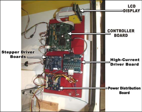
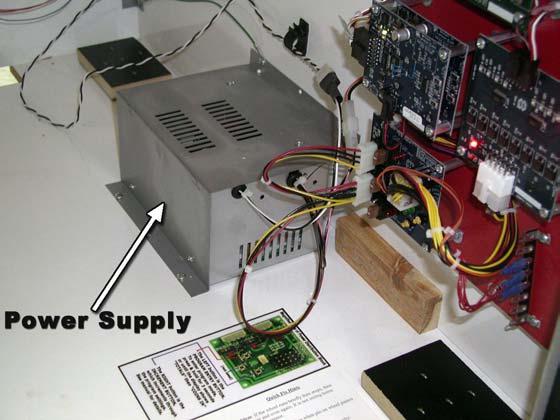
9 Parts Identification 9
10 slam-a-winner ac power schematic 90 volts to 240 volts standby amp. 1.5 max. amp. 2 POWER INPUT BOX ON/OFF SWITCH d.p.s.t 5 AM P. FUSE BLACK 90/ 240 ac 50/60 hz COMPUTER POWE R CORD 5 AM P. FUSE WHITE EARTH GROUND CONNECTS TO ALL BONDED METAL PARTS GREEN/YELLOW 16 GA. BLACK - WHITE TWISTED PAIR from 90 to /60 hz ac volts input 110 WATT POWER SUPPLY 12 volt + 12 volt + 5 volt + 24 volt + 5 amp 5 amp 5 amp power distribution pcb. 12 volt + 12 volt + 5 volt + BLACK - WHITE TWISTED PAIR CABINET LA MP 90 watt halogen CABINET LA MP 23 WATT slam-a-winner connector location C- is smybol for connector opto wheel home ball opto receiver ball opto transmitter drop ball switch assy. coin chute ticket dispenser ball lift motor wheel motor C-1 (6 pin) C-2 (8 pin) C-3 (4 pin) C-4 (4 pin) C-5 (4 pin) computer chassic power supply 10
11 slam-a-winner front door pink-white pink-white cpu-j3-18 SPEAKER coin comparator red C-2 12v fuse f-a enable orange C-2 orange high current pcb j2-4 output green C-2 green cpu j3-15 drop ball switch C-2 red- cpu j3-11 drop switch lamp white- C-2 C-2 white- cpu-j2-19 ticket dispenser notch blue C-3 blue cpu j3-7 run white C-3 white cpu j2-9 red C-3 C-3 10 k 5 v (+) cpu j1-1 cpu j1-4 ticket level switch low ticket lamp C-6 pin 1 C-6 pin 2 11
12 ball ready switch n.c. slam-a-winner -green cpu j3-2 jackpot display 3 digit 1 red 5 volt dc clock 2 blue- cpu j2-20 latch 3 green-white cpu j data 6 grey-red cpu j2-21 credit display 2 digit 1 red 5 volt dc clock 2 blue- latch 3 green-white 4 5 data 6 white-brown cpu j2-10 halagon lamp balldrop solenoid grey- violet-white j2-1 j2-5 j1-5 high current driver blue j1-3 cpu j2-8 j2-10 j2-2 j1-4 j1-10 j2-4 orange white-green brown-white 5 volt (+) to coin mech enable cpu j2-15 cpu j2-4 12
13 slam-a-winner ball lift motor 30 ohm phase 1 phase 1 pink yel C-7 pin 4 C-7 pin 3 pink -white pink -white econo stepper pcb j j1-1 violet grey cpu 485 comm.1 cpu 485 comm.2 phase 2 phase 2 blue green C-7 pin 2 C-7 pin 1 red-white red-white blue-white j1-9 j1-2 j1-3 j1-4 orange 24 volt dc wheel motor 30 ohm phase 1 phase 1 pink yel C-4 pin 4 C-4 pin 3 white-violet -red econo stepper pcb 2 j1-8 1 j1-1 violet grey cpu 485 comm.1 cpu 485 comm.2 phase 2 phase 2 blue green C-4-pin 2 C-4 pin 1 white-blue brown- j1-9 j1-2 j1-13 j1-3 j1-4 orange 24 volt dc white-orange C-1 pin 4 wheel homeopto red C-1 pin 1 5 volt dc outer ring opto transmitter outer ring opto receiver C-1 pin 6 blue-orange cpu j3-1 inter ring opto transmitter 3 1 inter ring opto 2 receiver 3 1 t/s C-1 pin 5 C-1 pin 2 violet- cpu j3-10 t/s C-1 pin 3 13
To Purchase This Item, Visit BMI Gaming
 Table of Contents General Operation. 3 How Slam-A-Winner plays How the Wheel Scores How the Ball Lift works Programming Options... 4-6 Troubleshooting Guide. 7-8 Parts Identification 9 Schematics 10-13
Table of contents. Game Play. Game Set-up. Technical Description. Programming. Error Codes. Electronic Components. Game Specifications.
 Table of contents Game Play Game Set-up Technical Description Programming Error Codes Electronic Components Game Specifications Parts 2 Red Hot X-Treme 7s Game Play The object of Red Hot X-Treme 7s is
BIG WHEEL 1 or 2 player SERVICE MANUAL
 Issued to Production 20th August 1997 BIG WHEEL 1 or 2 player SERVICE MANUAL Produced by Harry Levy Amusement Contractor Ltd Pysons Road Industrial Estate Broadstairs, Kent, England CT10 2LF Tel *843 866464
USA Ticket Dave & Buster
 USA Ticket Dave & Buster Produced by: Harry Levy Amusement Contractor Ltd Patricia Way Pysons Road Industrial Estate Broadstairs Kent CT10 2LF Tel 0044 1843 866 464 Fax 0044 1843 860 144 email: info@harry-levy-amusements.com
FLIP 2 WIN SERVICE MANUAL
 FLIP 2 WIN SERVICE MANUAL NOTICE The Operator of this equipment is responsible for maintaining customer safety at all time. Details set forth in this document must be followed at all times. 9-24-2009 FOREWORD
ICEBALL FX Service Manual
 ICEBALL FX Service Manual Innovative Concepts in Entertainment 10123 Main Street Clarence, NY 14031 (716) 759-0360 Monday through Friday 8:30 am to 6pm Eastern Standard Time www.icegame.com 1 Table Of
LIL HOOPS INSTRUCTION MANUAL
 LIL HOOPS INSTRUCTION MANUAL VER. 1-03 BAY-TEK INC. 1077 EAST GLENBROOK DRIVE PULASKI, WI 54162 E-MAIL: service@bay-tek.com PHONE: (920) 822-3951 FAX: (920) 822-8936 TABLE OF CONTENTS TABLE OF CONTENTS
MANUAL VERSION FEBRUARY
 MANUAL VERSION FEBRUARY 2008 MAINTENANCE AND TROUBLESHOOTING Quick Troubleshooting: WARNING For your safety and to reduce risk of damage to your game read the Important Safety Information in Chapter 1-2
Smokin Token. Operating Instructions. C.P.U. Version ST8 Sound Version H8
 Smokin Token Operating Instructions C.P.U. Version ST8 Sound Version H8 Manual Revision 9/7/2000 Smokin Token Operating Instructions TABLE OF CONTENTS Introduction 3 Game Play 3 Changing Ticket Wheel Values
1993 Ltd - all rights reserved
 1993 Ltd - all rights reserved No part of this publication may be reproduced by any mechanical, photographic or electronic process, or in the form of phonographic recording, nor may it be stored in a retrieval
CD100 Series. Operators Manual SINGLE COLUMN CARD DISPENSER
 CD100 Series SINGLE COLUMN CARD DISPENSER Operators Manual Contents 1 Specifications...1 2 Installation...2 2.1 Unpacking and inspection...2 2.2 Installation...2 2.3 Electrical Connections...2 2.4 Initial
Sideshow installation and maintenance
 Sideshow installation and maintenance From machine serial number SW077 1 1. Installation 1.1 Unpacking 1.2 Assembling 1.3 Set up 2. Game operation 2.1 Gun consoles 2.2 Main cabinet 2.3 Target descriptions
Contents. Section 2: Electrical - Switches, Solenoids and Motors
 Contents Section 2: Electrical - Switches, Solenoids and Motors... 2-3 Switches...2-3 Switches A, B, C and D...2-4 Error Code A Switch...2-4 Error Code B Switch...2-5 Error Code C Switch...2-5 Error Code
To Purchase This Item, Visit BMI Gaming (800) Single player Sideshow installation and maintenance
 Single player Sideshow installation and maintenance") Single player Sideshow installation and maintenance 1 1. Installation 1.1 Unpacking 1.2 Assembling 1.3 Set up 2. Game operation 2.1 Gun consoles 2.2 Main cabinet 2.3 Target descriptions 2.3.1 Stars and
Single player Sideshow installation and maintenance 1 1. Installation 1.1 Unpacking 1.2 Assembling 1.3 Set up 2. Game operation 2.1 Gun consoles 2.2 Main cabinet 2.3 Target descriptions 2.3.1 Stars and
REC-11+ REMOTE RECEIVER UNIT
 Resetting The Programmable Features The installer may quickly and easily return all 17 programmable features back to the factory settings. Changing individual features were explained in detail in the previous
JBI Docupunch P33 Automatic Punch
 JBI Docupunch P33 Automatic Punch Instruction Manual Provided By http://www.mybinding.com http://www.mybindingblog.com TABLE OF CONTENTS SECTION I: INSTALLATION & TESTING: 1) Uncrating, Inspection & removal
PAC-MAN AIR HOCKEY. Air Hockey Table Owner s Manual. Assembly, operation and care instructions.
 PAC-MAN AIR HOCKEY Air Hockey Table Owner s Manual. Assembly, operation and care instructions. Contents Foreword... 2 Product Specifications... 3 Before Assembling... 4 Tools required for Assembling*...
Reference Manual /12
 DrillMaster Planter Drive Controller Reference Manual 612366-03/12 Table of Contents Description of Operation, Safety and Care.............. 1 Installation.................................... 2-3 Tractor
OPERATING INSTRUCTIONS AND SERVICE MANUAL RACETRACK SCOREBOARD MODEL MP-3805
 OPERATING INSTRUCTIONS AND SERVICE MANUAL RACETRACK SCOREBOARD MODEL MP-3805 TABLE OF CONTENTS 1. GENERAL INFORMATION 1.1 DESCRIPTION 1.2 IDENTIFICATION 1.3 DAMAGE 1.4 DAMAGE CLAIM PROCEDURE 2. INSTALLATION
MD10. Engine Controller. Installation and User Manual for the MD10 Engine Controller. Full Version
 MD10 Engine Controller Installation and User Manual for the MD10 Engine Controller. Full Version File: MartinMD10rev1.4.doc May 16, 2002 2 READ MANUAL BEFORE INSTALLING UNIT Receipt of shipment and warranty
GRANT-DILLING-HARRIS INC Capital Ave, Plano, Texas (972)
") GRANT-DILLING-HARRIS INC. 1701 Capital Ave, Plano, Texas 75074 (972)424-3531 TOUCH SELECT PROGRAMMING GUIDE FOR TOUCH SELECT 2000 & TOUCH SELECT II Instructional Overview Touch-Select 2000: There are 10
GRANT-DILLING-HARRIS INC. 1701 Capital Ave, Plano, Texas 75074 (972)424-3531 TOUCH SELECT PROGRAMMING GUIDE FOR TOUCH SELECT 2000 & TOUCH SELECT II Instructional Overview Touch-Select 2000: There are 10
OWNER S MANUAL. Version WW BAY-TEK INC East Glenbrook Drive Pulaski, WI Web site:
 OWNER S MANUAL Version WW-2.01 BAY-TEK INC. 1077 East Glenbrook Drive Pulaski, WI 54162 E-mail: service@bay-tek.com Web site: www.bay-tek.com Service:... (920) 822-3951 ext. 1102 Parts:... (920) 822-3951
! WARNING To avoid risk of electrical shock, personal injury or death; disconnect power to oven before servicing, unless testing requires power.
 Technical Information Double Oven Electric Range MER6555AAB/Q/W MER6751AAB/Q/S/W MER6755AAB/Q/S/W MER6775AAB/F/N/Q/S/W Due to possibility of personal injury or property damage, always contact an authorized
CONTROL BOX. Wiring the control box into the vehicle. +12V
 CONTROL BOX Once the display panel is in place, mount the control box within the connecting cable's distance (approximately 3 feet) and secure to the underside of the dashboard. This case does not have
OPERATING INSTRUCTIONS AND SERVICE MANUAL FOOTBALL SCOREBOARD MODEL MP-3455 WITH MP-3000 CONTROL
 OPERATING INSTRUCTIONS AND SERVICE MANUAL FOOTBALL SCOREBOARD MODEL MP-3455 WITH MP-3000 CONTROL EFFECTIVE S.N.XXXX, JAN 1, 1994 TABLE OF CONTENTS 1. General Information 1.1 Description 1.2 Identification
POOL PILOT SOFT TOUCH OPERATING, TROUBLESHOOTING AND TECHNICAL CHEAT SHEET
 POOL PILOT SOFT TOUCH OPERATING, TROUBLESHOOTING AND TECHNICAL CHEAT SHEET NORMAL OPERATING MODE OF SOFT TOUCH 1. Output Lights will pulsate to indicate Chlorine production. a. There are 7 lights to indicate
CONTROLLER DIAGNOSTIC GUIDE
 Proprietary tice: This document contains proprietary information which not to be reproduced, transferred, to other documents, disclosed to others, used for manufacturing or any other purpose without the
To Purchase This Item, Visit BMI Gaming (800) Overview
 Overview") FIVE STAR REDEEMPTION OCTOSCORE MEGA SINGLE PLAYER TECHNICAL MANUAL June 0, 203 Features Bright Attention Grabbing Graphics & Cabinet Hot looking Lights Exciting Super Fast Skill Stop Oversized Highly
FIVE STAR REDEEMPTION OCTOSCORE MEGA SINGLE PLAYER TECHNICAL MANUAL June 0, 203 Features Bright Attention Grabbing Graphics & Cabinet Hot looking Lights Exciting Super Fast Skill Stop Oversized Highly
Laboratory 10 Assignment. Introduction
 ME576 Laboratory 10 Assignment Introduction For this lab, the conveyor trainer will be operated using the Siemens S5 PLC. The conveyor system is supposed to sort the metal pegs from rings on the moving
Trip 2, 2L, 3 and 5W Owner s Manual. ENGLISH
 Trip 2, 2L, 3 and 5W Owner s Manual. ENGLISH WELCOME. Thank you for buying a Bontrager Trip computer. We hope this computer gives you miles (or kilometers) of pleasure. Your Trip computer may not include
Maxx 3 Installation Guide
 Maxx 3 Installation Guide 2002 Directed Electronics, Inc. Vista, CA N840003 4-02 Table of Contents Important Information....................................................... 3 System Components........................................................
RFID SECURITY SYSTEM #WI-RFID. Before you start ANY electrical work; always disconnect the POWER at the BATTERY before doing ANYTHING.
 RFID SECURITY SYSTEM #WI-RFID Thank you for buying a StreetWorks product. Be confident that it will provide the quality and performance that you demand for your car. Please read and understand all installation
Water Specialist EE Control Valve Programming and Cover Drawing Manual
 Water Specialist EE Control Valve Programming and Cover Drawing Manual Page 2 EE Man u al EE Man u al Page 3 Table of Contents EE Front Cover and Drive Assembly... 4 Regeneration and Error Screens, Button
! WARNING To avoid risk of electrical shock, personal injury or death; disconnect power to oven before servicing, unless testing requires power.
 Technical Information Double Oven Dual Fuel Range JDR8895AAB/S/W Due to possibility of personal injury or property damage, always contact an authorized technician for servicing or repair of this unit.
OPERATING MANUAL Digital Diesel Control Remote control panel for WhisperPower generator sets
 Art. nr. 40200261 OPERATING MANUAL Digital Diesel Control Remote control panel for WhisperPower generator sets WHISPERPOWER BV Kelvinlaan 82 9207 JB Drachten Netherlands Tel.: +31-512-571550 Fax.: +31-512-571599
Ebling Back Blade Snow Plow Wireless Controller Kit Only sold by SnowplowsPlus.com and ControlAllWireless.com
 Ebling Back Blade Snow Plow Wireless Controller Kit Only sold by SnowplowsPlus.com and ControlAllWireless.com WARNING Always unplug the plow or shut off the battery breaker when in transport or not in
Operation Manual SPIDER WEB WARNING. Be sure read this Operation Manual before using your machine to ensure safe operation.
 Operation Manual SPIDER WEB WARNING Be sure read this Operation Manual before using your machine to ensure safe operation. SERVICE: Bromley Inc 420 Crossen Elk Grove Village, Illinois 60007 Tel: 847-427-0639-1
Automotive Application ET01 Software Revision A 12/06
 Automotive Application ET01 Software Revision A 12/06 INTRODUCTION... 2 FUNCTIONAL DESCRIPTION... 3 INSTALLATION... 4 COMPONENT PLACEMENT... 4 PLUMBING AND WIRING... 5 MSBC OPERATION (ET-01)... 14 TIMED
WHISTLE STOP OWNER S MANUAL. Version WS-1.15
 WHISTLE STOP OWNER S MANUAL Version WS-1.15 BAY-TEK INC. 1077 East Glenbrook Drive Pulaski, WI 54162 E-mail: service@bay-tek.com Web site: www.bay-tek.com Service:...(920) 822-3951 ext. 1102 Parts:...
Validator and Control Board Update Instructions for BC1
 Validator and Control Board Update Instructions for BC1 Installation Overview The update kit for the Rowe BC1 enables the changer to interface with a Mars AE/VN 120-volt validator. The validator determines
EIB To: Distribution From: Engineering Date: 15 August 1997 Subject: Denomination Conversion Reference: None. Decals. Denomination Plexiglass
 EIB 97009; Denomination Conversion Engineering Information Bulletin EIB 97009 To: Distribution From: Engineering Date: 15 August 1997 Subject: Denomination Conversion Reference: None This EIB describes
Do isolate the power supply from other high power systems such as Stereos and Alarms
 Thank you for purchasing a Smart Ride Air Management System, AIRBAGIT.COM s premier flagship product. This system will meet all of your custom and utility needs and will provide you years of trouble free
! WARNING To avoid risk of electrical shock, personal injury, or death, disconnect power to range before servicing, unless testing requires power.
 Electric Freestanding Range Technical Information MER5875RA* Due to possibility of personal injury or property damage, always contact an authorized technician for servicing or repair of this unit. Refer
CHAPTER S e t u p NOTICE:
 CHAPTER Setup NOTICE: Information in this manual may change without notice. Midway Games West Inc. reserves the right to make improvements in equipment function, design, or components as progress in engineering
Contents. Section 2: Electrical - Switches, Solenoids and Motors
 Contents Section 2: Electrical - Switches, Solenoids and Motors... 2-3 Switches... 2-3 Switches A, B, C and D... 2-4 Error Codes A Switch... 2-4 Error Codes B Switch... 2-4 Error Codes C Switch... 2-5
MEGA WAY LCD 4-CHANNEL CAR ALARM SECURITY SYSTEM. Installation Manual MEGATRONIX CALIFORNIA, USA MEGA 2500 INSTALL 1
 MEGA 2500 2-WAY LCD 4-CHANNEL CAR ALARM SECURITY SYSTEM Installation Manual MEGATRONI CALIFORNIA, USA MEGA 2500 INSTALL 1 MEGA 2500 INSTALL 2 INSTALLATION DIAGRAM H8: 10 Pin White Mini Connector H8 10
! WARNING To avoid risk of electrical shock, personal injury or death; disconnect power to range before servicing, unless testing requires power.
 Double Oven Electric Range Technical Information MER6765BA* Due to possibility of personal injury or property damage, always contact an authorized technician for servicing or repair of this unit. Refer
Table of Contents. 1. Copyright. 2. Warranty
 Table of Contents 1. Copyright 2. Warranty 3. Safety Instructions. 3.1 Product Safety 3.2 Electrical Safety General 3.3 Chemical Safety 3.4 Fire Safety 3.5 Disposal of Hazardous Components 4. Installation
Roll Up Door Operator
 INSTRUCTIONS & OWNERS MANUAL Roll Up Door Operator 2 INDEX Preparation before installation 4. Terms and definitions 5. Pictures & names of parts 6. Mounting the weight bar 7. Installing the operator 7.
GLM SERIES CONTROL Users Manual Rev:
 GLM SERIES CONTROL Users Manual Rev: 808062 Connecting Power Page 2 Motor Terminal Wiring Diagrams Page 3 Getting Started / Setup Page 4 1. Obstruction Detection Devices Page 4 2. Checking Power and Direction
CRUISE CONTROL SPEED LIMITER Rev. 4.0
 INSTALLATION f MANUAL CRUISE CONTROL & SPEED LIMITER AP900Series SL900Series 231.0004530 Rev. 4.0 1 2 CONTENTS: Chapters 1 Kit contents. 3 2 Tools required 4 3 Electronics module location... 5 4 Input
OWNERS AND SERVICE MANUAL INNOVATIVE CONCEPTS IN ENTERTAINMENT INC MAIN STREET, CLARENCE, NY SERVICE: FAX:
 OWNERS AND SERVICE MANUAL INNOVATIVE CONCEPTS IN ENTERTAINMENT INC. 10123 MAIN STREET, CLARENCE, NY 14031 SERVICE: 1-716-759-0360 FAX: 1-716-759-0884 E-MAIL: service@icegame.com WEBSITE: www.icegame.com
PULSE-8: MASTER PULSATION CONTROL
 PULSE-8: CONTROL Version - February 2006 For Software Version V1.02 Part Number - 39-0020 CONTROL: INDEX GOOD PRACTICE: Mains Supply. A separate mains supply and earth running directly from the consumer
ELECTRICAL SYSTEM RP-7
 ELECTRICAL SYSTEM RP-7 This section of the manual does not include integral electrical components of the engine. Refer to section Engine RP-1 for details. This section of the manual is divided into three
Contents. Section 3A: Consolidated Electronics... 3A-3. General Information... 3A-3
 Contents Section 3A: Consolidated Electronics... 3A-3 General Information... 3A-3 Consolidated High Voltage Box... 3A-5 Left Side... 3A-5 Right Side... 3A-6 Bottom... 3A-7 Internal... 3A-8 Lane Power Contactors...
DC Gamesman Technical Manual WMS Appendix TSP084.doc Issue 1.7 Aug 2005
 This document is the copyright of Money Controls Ltd and may not be reproduced in part or in total by any means, electronic or otherwise, without the written permission of Money Controls Ltd. Money Controls
3200NT Timer Service Manual
 Service Manual Valve Serial Number Valve Position 1-LEAd 2-LAg 3-LAg 4-LAg IMPORTANT: Fill in pertinent information on page 3 for future reference. Table of Contents Job Specifications Sheet.....................................................................
Therm-L-Tec Building Systems LLC. Therm-L-Tech. Power Operated Retrofit Kit 230 VAC or 440/480 VAC 50/60 Hz Installation and Setup Manual
 Therm-L-Tec Building Systems LLC Therm-L-Tech Power Operated Retrofit Kit 230 VAC or 440/480 VAC 50/60 Hz Installation and Setup Manual Rev. A 01/2015 Index Index 1 Electrical Requirements for Therm-L-Tec
OPERATING INSTRUCTIONS AND SERVICE MANUAL BASEBALL SCOREBOARD MODEL MP-3310 WITH MP-2002 CONTROL
 OPERATING INSTRUCTIONS AND SERVICE MANUAL BASEBALL SCOREBOARD MODEL MP-3310 WITH MP-2002 CONTROL EFFECTIVE S.N.XXXX, APRIL 1, 1996 1. General Information TABLE OF CONTENTS 1.1 Description 1.2 Identification
Table of Contents. Timer Identification Timer ID BLU-U Features: 1K 6K BLU-U Features 1K 6K
 DUSA Pharmaceuticals, Inc. Table of Contents Go to Chart # Timer Identification Timer ID BLU-U Features: 1K 6K BLU-U Features 1K 6K BLU-U Features: 10K BLU-U Features 10K BLU-U Symptom Fans Running, Timer
BSR Magic Box Digital ignition control for 4, 6, or 8 cylinder engines
 BSR BSR Magic Box Digital ignition control for 4, 6, or 8 cylinder engines Features Digital Advance The main feature of the Magic Box is the digital advance that replaces conventional weights and springs.
SUPER CAPACITOR CHARGE CONTROLLER KIT
 TEACHING RESOURCES ABOUT THE CIRCUIT COMPONENT FACTSHEETS HOW TO SOLDER GUIDE POWER YOUR PROJECT WITH THIS SUPER CAPACITOR CHARGE CONTROLLER KIT Version 2.0 Teaching Resources Index of Sheets TEACHING
CHUCK E CHEESE CHOO CHOO. A computer controlled model railroad redemption game.
 CHUCK E CHEESE CHOO CHOO A computer controlled model railroad redemption game. TABLE OF CONTENTS 1. UNPACKING INSTRUCTIONS Page 2. SETUP INSTRUCTIONS Page 3. OVERVIEW OF TRAIN Page 4. TRAIN OPERATIONS
Installation Instructions & Users Manual
 Installation Instructions & Users Manual UTILITY/ BUILDING INPUT 120 VAC ( OPTION) 15-20A N L CONTROL BOARD G SECURITY LIGHTING POWER SUPPLY (OPTION) CHARGER- POWER SUPPLY ASSBY XFMR (OPTION) CBM MODEL
Water Specialist EI Control Valve Programming and Cover Drawing Manual
 Water Specialist EI Control Valve Programming and Cover Drawing Manual Page 2 EI Man u al EI Man u al Page 3 Table of Contents EI Front Cover and Drive Assembly... 4 Regeneration and Error Screens... 5
PRODUCT MANUAL Desktop LED Dimmer and Receiver
 Product Description Solid Apollo s premium Desktop LED Dimmer is specifically designed as a tabletop dimmer. The elegant and seamless design perfectly complements any modern environment. The dimmer and
Power Operated Retrofit Kit for Manual Door 230 VAC or 440/480 VAC 50/60 Hz Installation and Setup Manual
 Therm-L-Tec Building Systems LLC Therm-L-Tech Power Operated Retrofit Kit for Manual Door 230 VAC or 440/480 VAC 50/60 Hz Installation and Setup Manual Rev. A 10/2014 Index Index 1 Electrical Requirements
SECOND GENERATION Use this guide with unit serial number prefix beginning with BWF using Terra Power separator.
 Technical Information and Diagnostic Guide for SECOND GENERATION Use this guide with unit serial number prefix beginning with BWF using Terra Power separator. This guide will assist you in becoming more
GLMB209DBC GLMB209DQC GLMB209DSC PLMB209DCD
 Product No. GLMB209DBC GLMB209DQC GLMB209DSC PLMB209DCD Market North America North America North America North America Color black bisque white stainless steel Volts 120 120 120 120 Watts 1200 1200 1200
Parker AC10 Frequency Inverter (to 22kW) Easy Start Guide
 Easy Start Guide") Parker AC10 Frequency Inverter (to 22kW) Easy Start Guide CAUTION: 1)Do not re-set while the motor is rotating 2)Perform parts replacement after discharge is finished 3)Do not connect output terminals
Parker AC10 Frequency Inverter (to 22kW) Easy Start Guide CAUTION: 1)Do not re-set while the motor is rotating 2)Perform parts replacement after discharge is finished 3)Do not connect output terminals
MS-1771 User Guide. Caution! Hazardous voltages are present inside amplifier components. Caution! The MS-1771 can produce high sound pressure levels.
 1 MS-1771 MS-1771 User Guide MS-1771W The MS-1771 is a high powered bi-amped rotary speaker system deigned for use with console Organs. Modern technology is used in both electronic and mechanical design
Installation & Service Manual
 Installation & Service Manual for M² Sync Slideout Control Box #1510000122 CONTENTS Introduction Installation Installation Problems Program Mode Operation Mode Preventative Maintenance Fault Diagnostics
System III Wiring Information 54-12
 System III Wiring Information 54-12 System Operation General Information Initial Power On Description of Revisions: This service bulletin is updated and replaces the version dated September 2002. This
VS 315 DELUXE 4-CHANNEL MOTORCYCLE ALARM. Installation And Operation Manual MEGATRONIX CALIFORNIA, U.S.A. VS 315 1
 VS 315 DELUXE 4-CHANNEL MOTORCYCLE ALARM Installation And Operation Manual MEGATRONIX CALIFORNIA, U.S.A. VS 315 1 VS 315 2 INSTALLATION We recommend insulating all your soldered or crimped connections
OWNER S MANUAL Version SH August 8, 2008
 OWNER S MANUAL Version SH1-0101 August 8, 2008 BAY TEK GAMES, INC. 1077 East Glenbrook Drive Pulaski, WI 54162 E-mail: service@baytekgames.com Web site: www.baytekgames.com Service:... (920) 822-3951 ext.
INSTALLATION MANUAL SPECTRUM BRAKE CONTROL
 INSTALLATION MANUAL 51170 SPECTRUM BRAKE CONTROL TABLE OF CONTENTS Controls & Components Tools List Before You Begin Wiring Wiring Diagram Mounting the LED Display Rotary Knob Wiring the Plug Connector
Service Manual Gulf Stream Electronic Full Wall Slide Systems
 Service Manual Gulf Stream Electronic Full Wall Slide Systems CONTENTS Page Before you operate the slide system 2 Operating Instructions 3 Preventive maintenance 3 Manually overriding your slide system
P3 Electronic Brake Control
 P3 Electronic Brake Control For 2, 4, 6 and 8 brake applications READ THIS FIRST: Read and follow all instructions carefully before installing or operating the P3. Keep these instructions with the Brake
Contents. Section 5: Adjustments Ball Detect Adjustment Transport Band Tension Adjustment
 Contents Section 5: Adjustments... 5-3 1. Ball Detect Adjustment... 5-3 2. Transport Band Tension Adjustment... 5-5 3. Transport Band Drive Belt Tension Adjustment... 5-7 4. Ball Cushion Adjustment...
! WARNING To avoid risk of electrical shock, personal injury, or death, disconnect power to range before servicing, unless testing requires power.
 Electric Freestanding Range Technical Information AER5712BA* MER5751BA* MER5752BA* MERH752BA* MERM752BA* Due to possibility of personal injury or property damage, always contact an authorized technician
SERVICE MANUAL. Standard Horizon PF-P310 Paper Folder
 SERVICE MANUAL Standard Horizon PF-P310 Paper Folder Read this manual, and thoroughly familiarize yourself with its contents before operating or servicing this equipment. PF-P310/SM FOREWORD Paper Folder
AIRSTREAM - BATTERY CONTROL CENTER - Diesel
 P/N 00-00755-000 CAUTION: The Battery Control Center is a centralized power switching, fusing, and distribution center. Power from both the chassis and coach batteries is fed into the box. The full power
CBM-105FN/FP Circuit Board
 CBM-105FN/FP Circuit Board Features Adjustable acceleration and deceleration time (0 to 2.5s) Stable speed operation Manual or automatic recovery of the thermal overload device One (1) rotary switch to
Troubleshooting Suggestions for Cables and Thermostats
 Troubleshooting Suggestions for Cables and Thermostats Toll Free Number: 800-537-4732 opt 5 E-mail: Easyheat.Technicalservices@Emerson.com Problem Possible Cause Suggested Correction No power to thermostat
CAUTION All safety information must be followed as provided in Service Manual
 Double Oven Gas Range Technical Information MGR6875AD* Due to possibility of personal injury or property damage, always contact an authorized technician for servicing or repair of this unit. Refer to Service
To Purchase This Item, Visit BMI Gaming (800) Overview
 Overview") To Purchase This Item, Visit BMI Gaming www.bmigaming.com (00) - +...00 FIVE STAR REDEEMPTION Haunted Hotel THREE PLAYER TECHNICAL MANUAL January,00 Features Bright Attention Grabbing Graphics & Cabinet
To Purchase This Item, Visit BMI Gaming www.bmigaming.com (00) - +...00 FIVE STAR REDEEMPTION Haunted Hotel THREE PLAYER TECHNICAL MANUAL January,00 Features Bright Attention Grabbing Graphics & Cabinet
Automatic Sliding Door Retrofit Drive Assembly. Installation Manual DoorControlsUSA.com
 Automatic Sliding Door Retrofit Drive Assembly Installation Manual 800-437-3667 DoorControlsUSA.com TABLE OF CONTENTS pg. 1. COMPONENTS 2 2. HEADER PREPARATION 2 3. DOOR PREPARATION 2 4. MOTOR AND CONTROLLER
Intelli-Feed Controller User s Manual Intelli-Feed Digital Tachometer and Hourmeter
 Intelli-Feed Controller User s Manual Intelli-Feed Digital Tachometer and Hourmeter Part #: 9047 Table of Contents: Table of Contents 2 Intelli-Feed TM User Interface 3 Equipment Diagnostic Indicators
BRIVIS DUCTED INVERTER SERVICE MANUAL DRCi
 BRIVIS DUCTED INVERTER SERVICE MANUAL DRCi 1 TABLE OF CONTENTS TABLE OF CONTENTS... 2 IMPORTANT NOTE... 3 FAULT FINDING AND DIAGNOSTICS... 3 ABBREVIATIONS... 3 PCB S... 4 OUTDOOR MAIN PCB... 4 INDOOR PCB...
MSD 7AL-3, Ignition Control PN 7230
 MSD 7AL-3, Ignition Control PN 7230 Important: Read the instructions before attempting the installation. Parts Included: 1-7AL-3, PN 7230 1 - Parts bag (wires and connectors) 4 - RPM Modules 3000, 7000,
Troubleshooting Guide
 Troubleshooting Guide 1 TABLE OF CONTENTS How To Use Guide...3 Figure 1...4 Figure 2......5 Electrical Problems...6 Vacuum Motor Problems...8 Fragrance Delivery Problems...10 Timer Problems...15 Coin/Bill
TERMINATOR User Manual
 TERMINATOR User Manual TERMINATOR User Manual Table of Contents Section Page 1 2 3 4 5 6 7 8 9 10 11 12 13 14 15 16 17 18 19 20 21 Introduction Safety Precautions Features and Benefits Overview of the
! WARNING To avoid risk of electrical shock, personal injury or death; disconnect power to oven before servicing, unless testing requires power.
 Technical Information Double Oven Electric Range MER6549BAQ/W MER6769BAQ/W Due to possibility of personal injury or property damage, always contact an authorized technician to service or repair this unit.
Induction Power Supplies
 Induction Power Supplies 7.5kW; 135 400kHz 480V version (Integral Heat Station) User s Guide Model 7.5-135/400-3-480 SMD Control Brds Rev. D 5/08 Table of Contents 1. Specifications and features...3 2.
User Instruction manual for Cardale Autoglide
 User Instruction manual for Cardale Autoglide NOTE TO INSTALLER: This user manual is supplied for the instruction of the end user. It contains important safety and warranty information. This manual MUST
FACTORY CONTACT INFORMATION
 FACTORY CONTACT INFORMATION Our Vision: We aspire to be the best in the world at developing and manufacturing coin operated games for our customers. BAY TEK GAMES INC. Pulaski Industrial Park 1077 East
Main 20 A fuse has blown (2) Connector has come off PCB
 Connector has come off PCB") ELECTRICAL FAULT FINDING OMS TRACTORS C & A from September 00 D&K series from April 00 JCB from Jan 00 Note: This Bulletin must be used in conjunction with the correct wiring diagram for the Tractor being
ELECTRICAL FAULT FINDING OMS TRACTORS C & A from September 00 D&K series from April 00 JCB from Jan 00 Note: This Bulletin must be used in conjunction with the correct wiring diagram for the Tractor being
INSTALLATION INSTRUCTIONS
 Total System Reset The 30 features, including the Selectable Coded Override, may be easily returned to the default settings. To perform this Total System Reset, follow these steps: Step 1 - Locate the
BKF Control Panel Instruction Manual for the Owners
 1 Contents 2 Exploitation and maintenance... 2 2.1 Control Panel (CP)... 2 2.1.1 Panel Operation... 2 2.1.2 Start Page... 2 2.1.3 Stands... 3 2.1.4 Osmosis... 3 2.1.5 Diagnostics... 4 2.1.6 Engine speed...
Service Manual Model S400 and S500 Smart Stand
 Service Manual Model S400 and S500 Smart Stand Form #1-145 Rev. 10/3/13 Table of Contents Parts Breakdown 3 Monthly Maintenance Checklist 7 Smart Stand Operating Instructions 9 Scale Calibration 10 Advanced