OWNERS AND SERVICE MANUAL INNOVATIVE CONCEPTS IN ENTERTAINMENT INC MAIN STREET, CLARENCE, NY SERVICE: FAX:
|
|
|
- Asher Houston
- 5 years ago
- Views:
Transcription


1 OWNERS AND SERVICE MANUAL INNOVATIVE CONCEPTS IN ENTERTAINMENT INC MAIN STREET, CLARENCE, NY SERVICE: FAX: WEBSITE: 1
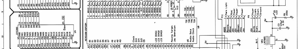
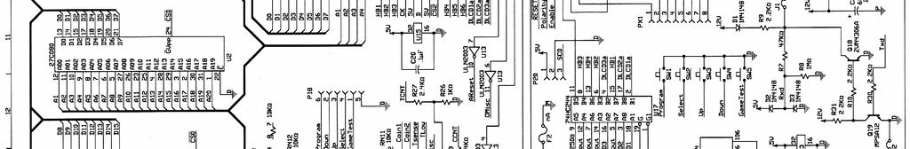
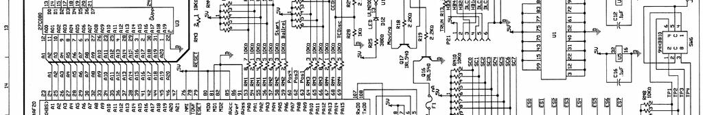
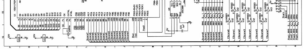
2 TABLE OF CONTENTS INTRODUCTION...PAGE 3 GAME FEATURES GAME PLAY INSTALLATION.... PAGE 4-7 BEFORE YOU BEGIN TOOLS NEEDED INSTALLATION SET-UP / TESTING......PAGE 8 SAFETY PRECAUTIONS PROGRAMMING YOUR GAME OPTION MODES ERROR CODES TESTING LINKED GAMES QUICK TROUBLESHOOTING PAGE 9 PROBLEMS AND SOLUTIONS DETAILED REPAIR...PAGE OPERATIONAL BACKGROUND MECHANICAL REPAIR ELECTRICAL / ELECTRONIC REPAIR MAINTENANCE PARTS LISTINGS.PAGE 15 SCHEMATICS...PAGE WARRANTY INFORMATION..PAGE ICEDOC RB9101 REVISION D
3 GAME FEATURES Thank you for your purchase of the new ALLEY ROLLER CLASSIC game from I.C.E. Through extensive testing and consultation with game operators, we have developed a game with all of the features and serviceability you ve been asking for. We have gone to great lengths to manufacture an Alley Roller game that is far easier to service and operate than anything before it. The features we have added, truly bring this game up to date. INTRODUCTION Another important feature of our game is the operator selectable Balls per game. This feature allows the operator to control how many balls the game will normally deliver. This amount is adjustable from 1 to 20 balls per game. It is however important to note that THE BALLS PER GAME IS NOT RELATED TO HOW MANY BALLS ARE IN THE GAME. The quantity of balls in the game is only for reference based on the normal 9 balls given in the traditional game. The game will work with 1 to 15 balls in the game, yet deliver the proper amount programmed into the game every time. (It is a good idea however to have at least 3 balls in the game to avoid slow play) The game starts off with unparalleled ease of assembly. The games go together in just a few minutes. The game cabinetry is a unique plywood construction with a special overlay for a superior finish. A special lacquer finish is applied over the wood for a beautiful rich, deep look. All of the cabinet panels interlock together, are reinforced with cleats and are glued together to produce a cabinet that can handle all of the abuse you can give it. Long life fluorescent lighting is used throughout the game to lower maintenance and create a bright playfield area. Even the ball return area is back lit to add to the appearance and serviceability of the game. Reliability is the name of the game with our new ball release assembly. With a specially engineered solenoid and double linkages, this mechanism has been tested to last for years. Best of all, the entire assembly simply lifts out of the cabinet with no tools needed! The best state of the art sound on sound audio is used to create an exciting atmosphere for the game player. Even our background theme is synchronized so all games play the theme at the same time, even when only one game is being played. ALLEY ROLLER CLASSIC allows the operator to give the players extra balls when a certain point threshold is reached. In addition, double scores can be awarded if desired. This extends the total points possible and adds a great deal to player appeal. These features also add excitement when used in conjunction with the optional Jackpot Marquee. All programming is accomplished from the Main P.C. Board which is conveniently located at the front end of the cabinet. This make servicing and adjusting as easy as turning a key. GAME PLAY Game play begins when a player has swiped his card through the card reader or inserts a coin. The player receives credit for one game. Additional card swipes give the player additional credits. As soon as the card is swiped, the balls release from the game and the game begins. The player throws balls at the target pockets and is awarded the points indicated on those pockets. The player continues to throw balls until they are all used up. If the player breaks a predetermined score during game play, he may be entitled to get Free Balls. At the end of the game, the player will receive credit for the tickets won. To receive the credit for the tickets, the player must swipe his card through the card reader. 3


4 BEFORE YOU BEGIN INSTALLATION REAR CABINET INSTALLATION WARNING: WHEN INSTALLING THIS GAME, A 3 PRONG GROUNDED A.C. RECEPTACLE MUST BE USED. FAILURE TO DO SO COULD RESULT IN SERIOUS INJURY TO YOURSELF OR OTHERS. FAILURE TO USE A GROUNDED RECEPTACLE COULD ALSO CAUSE IMPROPER GAME OPERATION, OR DAMAGE TO THE ELECTRONICS DO NOT DEFEAT OR REMOVE THE GROUNDING PRONG ON THE POWER CORD FOR THE SAME REASONS AS GIVEN ABOVE. USING AN IMPROP- ERLY GROUNDED GAME COULD VOID YOUR WAR- RANTY. HAVE A QUALIFIED ELECTRICIAN CHECK YOUR A.C. RECEPTACLE TO BE SURE THE GROUND IS FUNCTIONING PROPERLY. This installation is intended to be performed by a 2 man installation crew. No special electrical or "Electrician" skills are needed for installation, as all electrical connections are simple plug in types. 1. Remove all of the cabinets from their packaging and skids. 2. Position the back half of the alley cabinets as shown below. NOTE: ALL HARDWARE SHOULD BE LEFT LOOSE UNTIL ALL BOLTS HAVE BEEN ATTACHED TO- GETHER FOR ALL OF THE ALLEYS. 3. Loosely bolt all of the cabinets together in the rear as shown using the 1/4-20 x 2" bolts, nuts and flat washers. There is one bolt located in the bottom section. The following tools will be necessary for installation: Step ladder * Cordless Drill with Phillips head bit Diagonal cutters Ratchet with 5/16" socket 5/32" Allen wrench 3/16" Allen wrench #2 square drive bit (supplied) Measuring tape 7/16" Combination wrench Ratchet with 7/16" socket 2-6 receptacle outlet strips Heavy Duty extension cords* Utility Knife * Might be required in some situations. INSTALLATION 4. Remove the top display cover by sliding the plastic to the right. Now remove the two black plastic supports and slide the display board assembly up and out. 1. Remove the banding from the pallet. NOTE: BE SURE TO STAND TO THE SIDE WHEN CUTTING THE BANDS, AS THEY ARE UNDER PRESSURE, AND COULD SPRING OUT CAUSING INJURY. 2. Lift out all cage parts as well as any other parts shipped along with the game. 3. Remove the 2 game halves from the pallet. 4

 5.")


5 INSTALLATION ***NOTE: THE OUTSIDE CABINETS USE CARRIAGE BOLTS TO ATTACH THE LATCHES ON THE OUTSIDES AS SHOWN. The order of assembly is : Carriage bolt - cabinet - shim - latch - washer - Keep nut. (See below) 5. Loosely bolt the top fronts of the cabinets together as shown using the 1/4-20 x 2" bolts, nuts and flat washers. 6. Loosely install the cabinet latches using the 1/4-20 x 3" full thread bolts, nuts and flat washers and spacer plates as shown. The order of assembly is: Bolt - washer - latch - shim - cabinet - cabinet - shim - latch - washer - Keep nut. OUTSIDE CABINET 7. At this time, TIGHTEN ALL HARDWARE. 8. The rear cabinets should now be moved into place. THE CABINETS SHOULD BE MOVED EXACTLY 12 INCHES FROM THE BACK WALL AS MEASURED FROM THE LOWEST POINT ON THE CABINET. 6. Repeat the above step with all of the cabinets. there are 4 latches per cabinet.*** 12 5
 Joint connector nut (6) Connecting stud (3) Glass insulator bushing (3) Glass edge protector (3) NOTE: USE THE PROVIDED PHOTOGRAPHS TO GUIDE YOU THROUGH THE INSTALLATION. 1.")


6 INSTALLATION REAR CABINET INSTALLATION INSTALL THE GLASS PARTITIONS TO THE REAR CABINETS. You will need the following parts for each glass divider you install. HAVE THESE PARTS READY AHEAD OF TIME. Glass divider (1) Joint connector nut (6) Connecting stud (3) Glass insulator bushing (3) Glass edge protector (3) NOTE: USE THE PROVIDED PHOTOGRAPHS TO GUIDE YOU THROUGH THE INSTALLATION. 1. Slide a glass partition into the slotted area between the cabinets. 2. Slip a Glass insulator bushing into each of the three mounting holes. This will keep the glass from falling out and protect the glass from the hardware. 5. Place the remaining protector on the other side of the glass and secure with the Joint connector nut. 6. Install the remaining glass separators. NOTE: THERE ARE PLASTIC SPACER STRIPS THAT NEED TO BE USED BEHIND THE GLASS EDGE PROTECTORS ON THE OUTSIDE CABINETS. THESE ARE NEEDED TO TAKE UP THE SPACE SINCE THERE ARE NO OTHER CABINETS TO TAKE UP THE SPACE. 7. Tighten the hardware securely with an Allen wrench. 3. Screw the connecting studs into the ends of the Joint connector nuts. 4. Hold a Glass edge protector in place and run the Joint connector/stud thru the protector and thru the insulator. 6

7 INSTALLATION FRONT CABINET INSTALLATION 1. Unpack the front cabinets and set in front of the rear cabinets. STARTING AT ONE END AND WORKING YOUR WAY THROUGH, PERFORM THE FOLLOWING STEPS: 2. Open the ticket door and slide the left hand rail cover open. Release the wire harness to remove the rail cover off. Be careful not to destroy the key switch. 3. Connect all of the connectors from the rear and front cabinets together except the phone cords. 4. There are two phone cords for every alley. One cord has a female to female adaptor attached to it. This is meant to daisy chain the next alley together by connecting it s phone cord without the female to female adaptor. Continue to daisy chain each alley together. 5. Connect the alley s end that is female to the marquee male phone cord. This completes the daisy chain. THESE PHONE CORDS WILL BE USED TO "LINK" THE GAMES TO EACH OTHER AS WELL AS THE OVERHEAD MARQUEE. 6. At this time, run the A.C. power cord down the channel, thru the access holes and into the Power Module (A.C. switch) in the front cabinet under the Main P.C. Board drawer. 7. After all of the harnesses have been connected on the game, slide the front cabinet into position in front of the rear cabinet. MARQUEE INSTALLATION IT IS VERY IMPORTANT TO LINE UP THE CABINETS AS EXACTLY AS POSSIBLE. 1. Unpack and with two people place the marquee and center on to the top of the back cabinet assembly. 8. Slide the rail cover back on and slide the ticket drawer back in and lock shut. 2. Mark and drill the mounting holes. 9. Using a 5/16" 1/4" drive socket and ratchet, tighten the lock latches that connect the front and back cabinets as shown in the photograph. 3. Remove the front display cover by sliding it to the right and remove the two support bars as previous shown. Lift and remove the display board assembly to allow access underneath to install mounting hardware. NOTE: YOU ONLY HAVE TO TIGHTEN ONE SIDE, A THRU ROD AUTOMATICALLY TIGHTENS THE OTHER SIDE FOR YOU. 4. Replace display board assembly, support bar screws, and display cover. 10. Repeat this operation with all remaining cabinets. 5. Connect the phone cord to which ever end cabinet has the female to female adaptor attached. DON'T FORGET TO LINK THE GAMES WITH THE PHONE CORDS AS YOU GO. ** BE CAREFUL NOT TO STEP ON THE BALL JUMP OR DIRECTLY ON THE RAMP WHILE INSTALLING THE MARQUEE. KEEP FOOTING ONLY ON SIDE RAILS DURING MARQUEE INSTALLATION ** 7
8 PREPARING THE GAMES IMPORTANT: THE GAMES WILL NOT FUNCTION PROPERLY WITHOUT TICKETS. PLEASE LOAD TICKETS BEFORE PROCEEDING WITH PROGRAMMING AND TESTING. ERROR CODES SET-UP/GAME TESTING PROGRAMMING BUTTONS The programming buttons have multiple function. They will have certain functions in normal game play mode and different functions when in programming mode. NOTE: SINCE THE BUTTON FUNCTIONS CHANGE FROM MODE TO MODE, USE THE SWITCH NUMBERS TO DETERMINE PROPER FUNCTION. When the games are first turned on, it is possible that an error code could be displayed. NOTE: THE GAMES WILL NOT FUNCTION IF THEY ARE DISPLAYING AN ERROR CODE. Please review the error code and correct the error before proceeding. 1 = 0 Ball Return Sensor (top of the ball return) 2 = 1K Score Sensor 3 = 2K Score Sensor 4 = 3K Score Sensor 5 = 4K Score Sensor 6 = 10K Right Sensor 7 = 10K Left Sensor 8 = Ball Count Sensor (sensor at ball release) 9 = Coin Counter Disconnect 10 = Ticket Counter Disconnect 11 = Coin Switch Stuck 12 = Not Used 13 = Opto Net (tilt) Blocked 14 = Ball Release (key) Switch Stuck Closed 15 = Not Used 16 = Ball Trough Not Plugged In NOTE: IF YOU GET AN ERROR "0", PLEASE CALL OUR SERVICE DEPARTMENT. ALLEY INDICATORS The alley number indicators will normally be lit when the games are functioning properly and have a sufficient amount of tickets in the bin. When the ticket bin is nearly empty, the alley indicator will flash. When out of tickets, the alley indicator will go dark and the game will become inoperative. TO ENTER THE PROGRAMMING MODE, PRESS SW1 (PROGRAM). TO EXIT PROGRAMMING, PRESS THE BUTTON ONCE AGAIN. NORMAL GAME MODE VOLUME - SW4 Press this button repeatedly to scroll through the different volume levels. BALLS PER GAME - SW5 Press this button repeatedly to select between balls per game. Your selection will be shown on the display. Once you choose your value, the game will lock that amount into memory. PROGRAMMING MODE CHANGE TICKET VALUE - SW2 This button will change the value of the TICKET BONUS payout. each press of the button will increase the ticket value by 25. this will loop around from minimum to maximum. INCREASE SCORE - SW4 Pressing this button will increase the value of the score needed to win the ticket bonus by 1000 point increments. DECREASE SCORE - SW3 Pressing this button will decrease the value of the score needed to win the ticket bonus by 1000 point increments LINKED GAMES Each Alley Roller main board must be set to a different ID number when setup is complete and before power is applied. Your options are one through nine and zero which is equal to ten. The Marquee is set to fourteen and cannot be changed. 8
9 QUICK TROUBLESHOOTING GAME WILL NOT TAKE OR ADD MONEY CORRECTLY Micro switch not working or returning properly. Check and repair or replace as necessary. Game programming set-up incorrectly. Refer to service manual for proper settings. Bad harnessing or connector. Check w/ohm meter and repair if necessary. Bad Main P.C. Board. Check and repair or replace as necessary. GAME HAS NO SOUND Bad speaker. Check w/ohm meter for 8-ohm load and replace if defective. Volume level set incorrectly. Check service manual for volume setting procedures. Bad Harnessing or connector. Check w/ohm meter and repair if necessary. Bad Main P.C. Board. Check and repair or replace as necessary. BALLS WILL NOT RELEASE OR WILL NOT STOP RELEASING Solenoid burned out. Replace solenoid. Solenoid sticks in. replace solenoid. Release lever binding. Check or replace as necessary. Release return spring broken. Replace spring. Bad ball count sensor. Check and replace as necessary. Bad connector or harnessing. Check w/ohm meter and repair as necessary. Bad Opto-isolator. Check w/ohm meter and replace if necessary. Bad Main P.C. Board. Check and repair or replace as necessary. Debris jamming ball return system. Clean return area. GAME WILL NOT ADD POINTS CORRECTLY / COUNTS BALLS WHEN THROWN Bad score sensor. Check and repair or replace. Score sensor wiring bad. Check w/ohm meter and repair or replace. Cabinet harnessing bad. Check w/ohm meter and repair or replace as necessary. Sensors loose or misaligned. Realign sensors. Main P.C. Board bad. Check and repair or replace as necessary. TICKET DISPENSER DOES NOT WORK OR WORKS IMPROPERLY Bad harnessing. Check w/ohm meter and repair if necessary. Bad ticket dispenser. Repair or replace ticket dispenser. Dispenser out of tickets. Add tickets. Bad Main P.C. Board. Check and repair or replace as necessary. Optical sensor on dispenser dirty. Clean sensor. SCORE DISPLAY WILL NOT LIGHT OR WORKS IMPROPERLY No power on Main P.C. Board. Check transformer and fuses / check power module Bad connectors or harnessing. Check w/ohm meter and repair as necessary. Bad Display P.C. Board. Repair or replace as necessary. Bad Main P.C. Board. Repair or replace as necessary. NO FLUORESCENT LIGHTING Bad connectors or harnessing. Check w/ohm meter and repair as necessary. Bad ballast transformer. Replace ballast transformer. Bad bulb. Replace bulb. No A.C. power to game. Check main fuses in power module. GAMES ACT STRANGELY FOR NO APPARENT REASON Game I.D. s set improperly. Refer to service manual for proper settings. Game hit by electrostatic discharge. Turn games off, wait 15 seconds and turn back on. Bad Main P.C. Board. Check and repair or replace as necessary. MARQUEE DOES NOT WORK OR RESPOND CORRECTLY Linking cable not connected or damaged. Replace cable Marquee P.C. Board bad. Repair or replace P.C. Board Bad display P.C. Board. Repair or Replace P.C. Board Marquee Electronics Cabinet not plugged in or turned off. Check for A.C. Power. 9
10 WARNING: ALWAYS REMOVE POWER TO THE GAME BEFORE ATTEMPTING ANY SERVICE, UNLESS NEEDED FOR SPECIFIC TESTING. FAILURE TO OBSERVE THIS PRECAUTION COULD RESULT IN SERIOUS INJURY TO YOUR- SELF OR OTHERS. OPERATIONAL BACKGROUND The ALLEY ROLLER CLASSIC alley roller games have been designed with MODULAR repair in mind. The coin drawers and ticket drawers can be slid out and removed in their entirety to be worked on in another area if desired. The ball release assembly can be removed as a unit with no tools necessary, making repair a snap. DETAILED REPAIR If P.C. Boards are suspected as causing problems, check to see that all of the I.C. chips are firmly seated on the boards. If light bulbs are suspected, swap them with one that is known to work to narrow the problem down to the bulb or P.C. Board. MECHANICAL REPAIR BALL RELEASE ASSEMBLY WARNING: BE SURE POWER HAS BEEN REMOVED FROM THE GAME BEFORE PROCEEDING. The ball release system utilizes an A.C. Pull type solenoid that has been specifically designed to eliminate residual magnetism problems commonly found in this type of solenoid. The solenoid is powered via an Opto-isolator, to eliminate solenoid noise from the electronic circuitry. Other than the display, all electronics and power supply components are located on the Main P.C. Board to make modular type replacement fast and simple. Open the cash box drawer at least 6 inches. Pull forward on the ball release cover. (The panel with the clear plastic window) about 3 inches to disengage, then lift off. Remove the balls from the game. The display board has been designed to be very reliable and easy to repair. Very few drive components are necessary for this type of display. TROUBLESHOOTING PHILOSOPHY To find problems with the game, always first check what should be obvious. See that the game is plugged in and that all of the fuses on the game are good. This includes the fuse that is located INSIDE the power module. Next, check to see that all of the connectors are firmly seated and that none of the wires have pulled out of them. When trying to find out if specific components are bad or not, try swapping them with components from another player station to see if the problem moves with the component, or stays where it was. This will help you to know if you have a problem with a specific component, or maybe a problem with either the wiring or the Main P.C. Board. Use extreme caution when using probes or volt if the game is powered up. If doing continuity checks, it is important to disconnect the harnessing at both, as attached they may yield erroneous results. Grasp the release assembly by the rail and slowly lift out, being careful to avoid hitting the sensors on the cover retaining screws. Disconnect the connector that connects the release assembly to the game. 10


11 SOLENOID REPLACEMENT DETAILED REPAIR MARQUEE BULB REPLACEMENT Remove the spring from the solenoid and mounting bolt. Remove the cotter pin from the clevis pin and slide the clevis pin from the solenoid shaft and linkage. Carefully scribe a mark when removing the solenoid to be sure the replacement is properly located. Remove the hardware that secures the solenoid to the mounting plate. When re-assembling, be sure to use the same size cotter pin to retain the clevis pin, as this pin is needed to hold the spring to the solenoid assembly. Remove the A.C. power cord from the back of the marquee. Remove the nuts from the rear panel of the marquee and remove the front vacuum formed plastic marquee. Remove the bulb retaining clip. Pull the bulb straight out of the socket. Insert the new bulb into the socket and snap into place. Replace the bulb retaining clip. Re-assemble in reverse order. Be sure the bent over end of the cotter pin is trimmed so it cannot contact the solenoid body. PLAYFIELD BULB REPLACEMENT The bulbs replace easily. Remove the bolts that hold the bulb cover in place. Remove the Pull the bulb straight out of the socket. Insert the new bulb into the socket and snap into place. Replace the bulb retaining clip. Screw the cover back in place. ELECTRONIC REPAIR SCORE DISPLAY ASSEMBLY Remove the graphic header retaining strip on the end panel of the games display. Lift the display panel straight up, pull the bottom out and remove the panel. 11


12 DETAILED REPAIR Remove the two black plastic supports and lift the entire display assembly straight up, then pull the bottom forward and remove connector from the rear. Pull forward on the ball release cover. (The panel with the clear plastic window) about 3 inches to disengage, then lift off. Unscrew the display from the mounting bracket. Assemble in reverse order. MAIN P.C. BOARD Turn off A.C. power and remove the power cord from the power module. Open the front speaker door and pull the PCB tray out. Remove the balls from the game. Pivot the ball release cover upward and remove the top cover of the ball return channel to expose the sensor mounting bracket. Remove all P.C. Board connectors noting where each one connects into the board. Remove the 4 hex fasteners that retain the board to the mounting bracket. NOTE: THE FRONT CABINET MAY HAVE TO BE PULLED FORWARD TO BE ABLE TO SLIDE AND REMOVE THE TOP COVER. Re-assemble in reverse order. BALL COUNT SENSOR Turn off A.C. power and remove the power cord from the power module. Open the cash box drawer at least 6 inches. 12


13 DETAILED REPAIR From the inside of the ball channel, remove the six hex nuts that secure the sensors to the channel wall. Open cash drawer at least 6 inches. Pull forward on the ball release cover. (The panel with the clear plastic window) about 3 inches to disengage, then lift off. Remove the balls from the game. Pivot the ball release cover upward. Remove the black screw from the rear cabinet, just behind the top cover. Slide the top cover of the ball return channel upward to expose the sensor mounting bracket. NOTE: THE FRONT CABINET MAY HAVE TO BE PULLED FORWARD TO BE ABLE TO SLIDE AND REMOVE THE TOP COVER. Unscrew the sensor assembly and remove. Replace sensor assembly. Assemble in reverse order. Unscrew the sensor assembly and remove. NOTE: BE SURE THE TRANSMITTER WIRING IS KEPT HIGH ENOUGH FOR THE BALLS TO PASS UNDER. IF THERE IS ANY SLACK, IT IS IMPORTANT TO REMOVE IT USING A TIE WRAP, ETC. Assemble in reverse order. NOTE: BE SURE THE TRANSMITTER WIRING IS KEPT HIGH ENOUGH FOR THE BALLS TO PASS UNDER. IF THERE IS ANY SLACK, IT IS IMPORTANT TO REMOVE IT USING A TIE WRAP, ETC. BALL RETURN SENSOR Turn off game power. The ball return sensor is located at the rear of the ball return channel where the 2 cabinets meet. 13

14 SCORE SENSORS Remove all A.C. power from the game. Lift the playfield up and support with the prop rod. DETAILED REPAIR Remove the screws that hold the sensor in place and replace the sensor. Re-connect power to the game. Run your hand through each sensor pair during a game and listen for the sound to indicate proper function. If the sensor still does not indicate proper function, check for bad harnessing or Main P.C. Board. 0 COUNT SENSOR Open the center cover to the ball release mechanism. lift and slide the right rear channel cover off of the alley. Replace the sensor and re-assemble in reverse order. 14
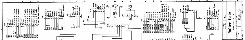
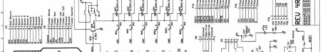
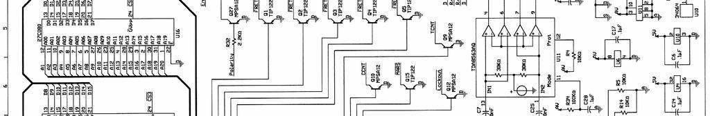
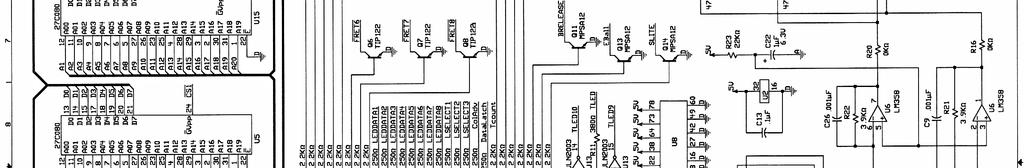
15 MECHANICAL PARTS PARTS LISTINGS GRAPHICS & DECALS 1024 Ticket Bin 1026 Ticket Bin Switch Mounting Bracket 5014 Coin Door Lock 5014CE LOCK - KEY SWITCH 5101 Mech Holder 6105 Latch Tool 6111 Fiber Lever Washer 6117 Clevis Pin 3/ Clevis Pin 1 AR1001 Ball Rail AR1002 Ball Return Tray AR1003 Rail Support Spacer AR1004 Ball Release Lever Spring RB1005 Cash Box AR1007 Solenoid Linkage AR1009 Ball Release Lever Bracket AR1018 Ball Release Lever AR1020 Cup Connecting Plates AR3006 Playfield Light Cover AR3008 PL7 Light Diffuser AR3015 Cup, Bottom Ring AR3017 Insulating Grommet AR3020 Runaway Ball Bumper Material AR3021 Ball Stop Grommet RB3124 Ball (Blue) AR3065 Runaway Ball Bumper Cap, Left Side AR3066 Runaway Ball Bumper Cap, Right Side NA3016X Ball Diverter AR3101 Ball Jump RB1042 Channel Cover Right (Front) RB1043 Channel Cover Right (Middle) RB1044 Channel Cover Right (Rear) RB1045 Target Prop Rod RB1111 Channel Cover, LEFT RB3003 Playfield Hole Guard RB3005 Ball Cover Window RB3030 Spacer (Glass) RB3033 Glass (Partition) RB3100 Runway Material (Red) RB4004 Bumper AR7003 Coin Door Decal AR7004 Ticket Door Decal AR7008 Instruction Panel AR7201 Display Panel AR7221 Programming Decal (Part 1) AR7222 Programming Decal (Part 2) RB7014 Overlay, 10,000 Point (Left) RB7015 Overlay, 5,000 Point RB7016 Overlay, 4,000 Point RB7017 Overlay, 3,000 Point RB7018 Overlay, 2,000 Point RB7019 Overlay, 1,000 Point RB7020 Overlay, 10,000 Point (Right) RB9101 Service Manual RB7009 Fuse Rating Decal ELECTRICAL / ELECTRONIC PARTS 211 Low Ticket Switch 248 PL7 Transformer 249 PL7 Bulb 251 PL7 Socket 2111 Solid State Relay Ft. Modular Phone Cord 8312 BULB PL-L 40W AR2007 Speaker 6 X 9 AR2008 Solenoid CL Ft. Computer Style Power Cord DA2002X Transformer DA2033X PCBA - (Small Display) HH5005 Ticket Dispenser (Entropy) PC20224 Counter, 12 Volt D.C. PC20429 Red Diffused L.E.D. RB2032X PCBA - (Large Display) RB2009AX PCBA - (Opto Sense Point) RB2009BX PCBA - (Opto Sense Point Zero) RB2009CX PCBA - (Opto Sense Ball Count) RB2009X PCBA - (Opto Sense Point 10K) RB2034X Main P.C. Board Assembly PLEASE CALL OUR SERVICE DEPARTMENT FOR HELP WITH ANY PARTS NOT SHOWN ON THIS LIST MON-FRI 9:00 AM TO 6:00 PM EST PHONE FAX
16 16 18
17 DA2001X Power supply 17 19
18 RB2039X Left Side (Receiver) 18 20
19 RB 2040X Right side (Transmitter) 19

20 WARRANTY POLICY I.C.E. Inc warrants all components in new machines to be free of defects in materials and workmanship for the period listed below: 180 days on Main PCB s, Computers & Motors 1 year on all LCD monitor panels 90 days on all other electronic and mechanical components 30 days on all I.C.E. repairs and parts purchases I.C.E. Inc shall not be obligated to furnish a warranty request under the following conditions: Equipment or parts have failed through normal wear and tear Equipment has been subjected to unwarranted stress, abuse or neglect Equipment has been damaged as a result of arbitrary repair/modification Products will only be covered under warranty by obtaining an I.C.E. authorized RMA #. To obtain an RMA # please provide I.C.E. tech support with the game serial # or original I.C.E. invoice # and a detailed description of the failure or fault symptoms. I.C.E. Inc will assume no liability whatsoever for costs associated with labor or travel time to replace defective parts. All defective warranty covered components will be replaced with new or factory refurbished components equal to OEM specifications. I.C.E. Inc will cover domestic UPS ground, or comparable shipping costs during the warranty period. International or expedited shipments are available for an additional charge. To obtain credit defective parts must be returned to I.C.E. Inc, at the customer s expense, within 30 days. After 30 days a 15% re-stocking fee will apply to all returns. ICE distributors are independent, privately owned and operated. In their judgment, they may sell parts and/or accessories other than those manufactured by I.C.E. Inc. We cannot be responsible for the quality, suitability or safety of any non-i.c.e. part or modification (including labor) that is performed by such a distributor. Innovative Concepts in Entertainment Main St. Clarence, NY Phone #: (716) Fax #: (716)
To Purchase This Item, Visit BMI Gaming (800)
") OWNERS AND SERVICE MANUAL INNOVATIVE CONCEPTS IN ENTERTAINMENT INC. 10123 MAIN STREET, CLARENCE, NY 14031 SERVICE: 1-716-759-0360 FAX: 1-716-759-0884 E-MAIL: service@icegame.com WEBSITE: www.icegame.com
OWNERS AND SERVICE MANUAL INNOVATIVE CONCEPTS IN ENTERTAINMENT INC. 10123 MAIN STREET, CLARENCE, NY 14031 SERVICE: 1-716-759-0360 FAX: 1-716-759-0884 E-MAIL: service@icegame.com WEBSITE: www.icegame.com
MANUAL VERSION FEBRUARY
 MANUAL VERSION FEBRUARY 2008 MAINTENANCE AND TROUBLESHOOTING Quick Troubleshooting: WARNING For your safety and to reduce risk of damage to your game read the Important Safety Information in Chapter 1-2
ICEBALL FX Service Manual
 ICEBALL FX Service Manual Innovative Concepts in Entertainment 10123 Main Street Clarence, NY 14031 (716) 759-0360 Monday through Friday 8:30 am to 6pm Eastern Standard Time www.icegame.com 1 Table Of
DOWN THE CLOWN - Flat Top Service Manual Innovative Concepts in Entertainment Main Street Clarence, NY 14120
 DOWN THE CLOWN - Flat Top Service Manual Innovative Concepts in Entertainment 10123 Main Street Clarence, NY 14120 1 2 Table of Contents Safety, Warnings, and Power Requirements 4 Hardware 5 Setup 6-16
To Purchase This Item, Visit BMI Gaming (800)
") OWNERS AND SERVICE MANUAL INNOVATIVE CONCEPTS IN ENTERTAINMENT INC. 10123 MAIN STREET, CLARENCE, NY 14031 SERVICE: 1-716-759-0360 FAX: 1-716-759-0884 E-MAIL: service@icegame.com WEBSITE: www.icegame.com
OWNERS AND SERVICE MANUAL INNOVATIVE CONCEPTS IN ENTERTAINMENT INC. 10123 MAIN STREET, CLARENCE, NY 14031 SERVICE: 1-716-759-0360 FAX: 1-716-759-0884 E-MAIL: service@icegame.com WEBSITE: www.icegame.com
To Purchase This Item, Visit BMI Gaming
 Table of Contents General Operation. 3 How Slam-A-Winner plays How the Wheel Scores How the Ball Lift works Programming Options... 4-6 Troubleshooting Guide. 7-8 Parts Identification 9 Schematics 10-13
Table of contents. Game Play. Game Set-up. Technical Description. Programming. Error Codes. Electronic Components. Game Specifications.
 Table of contents Game Play Game Set-up Technical Description Programming Error Codes Electronic Components Game Specifications Parts 2 Red Hot X-Treme 7s Game Play The object of Red Hot X-Treme 7s is
OWNERS AND SERVICE MANUAL INNOVATIVE CONCEPTS IN ENTERTAINMENT INC MAIN STREET, CLARENCE, NY SERVICE: FAX:
 OWNERS AND SERVICE MANUAL INNOVATIVE CONCEPTS IN ENTERTAINMENT INC. 10123 MAIN STREET, CLARENCE, NY 14031 SERVICE: 1-716-759-0360 FAX: 1-716-759-0884 E-MAIL: service@icegame.com WEBSITE: www.icegame.com
Table of Contents. General Operation. 3 How Slam-A-Winner plays How the Wheel Scores How the Ball Lift works Programming Options...
 61-MAN-B Table of Contents General Operation. 3 How Slam-A-Winner plays How the Wheel Scores How the Ball Lift works Programming Options... 4-6 Troubleshooting Guide. 7-8 Parts Identification 9 Schematics
Installation and Service Manual
 RESIDENTIAL PLATFORM LIFTS RPL400 / RPL600 Installation and Service Manual WARNING! STRICT ADHERENCE TO THESE INSTALLATION INSTRUCTIONS IS REQUIRED to promote the safety of those installing this product,
BIG WHEEL 1 or 2 player SERVICE MANUAL
 Issued to Production 20th August 1997 BIG WHEEL 1 or 2 player SERVICE MANUAL Produced by Harry Levy Amusement Contractor Ltd Pysons Road Industrial Estate Broadstairs, Kent, England CT10 2LF Tel *843 866464
QUADBOSS UTV STRAIGHT PUSH TUBE OWNER S MANUAL
 PAGE of 6 PART #938 QUADBOSS UTV STRAIGHT PUSH TUBE OWNER S MANUAL This owner s manual covers all aspects of your new push tube including assembly, replacement parts, installation, warranty, and troubleshooting.
Installation Instructions Z-Gate Shifter
 Installation Instructions Z-Gate Shifter Part Number 80681 1998, 2001 by B&M Racing and Performance Products The B&M Z-Gate shifter can be used in vehicles equipped with most popular three speed automatic
MOTORIZED FOLDING CAMPER WINCH
 OWNER'S MANUAL MOTORIZED FOLDING CAMPER WINCH With 1200lb Lift Capacity The 12 Volt Motorized Folding Camper Winch is used to raise and lower folding campers with the touch of the switch, eliminating hand
AL625 & AL625HD INSTALLATION & OWNER S MANUAL
 AL625 & AL625HD INSTALLATION & OWNER S MANUAL These instructions are provided to assist you in the installation of the AL625. If you require further assistance, our trained staff is ready to provide you
***THE OWNER'S MANUAL MUST BE GIVEN TO THE END USE CUSTOMER AFTER COMPLETING THE INSTALLATION.***
 INSTALLATION INSTRUCTIONS FOR THE MOTOR TRIKE HARLEY MECHANICAL REVERSE 1999-2006 FIVE SPEED FLH LAST UPDATED: OCTOBER 2011 AS THE INSTALLER OF THIS MECHANICAL REVERSE, YOU MUST BECOME FAMILIAR WITH PROPER
INSTALLATION MANUAL STEP SLIDER BD-SS-200-JK4. Made in the USA. Front Bracket Middle Bracket Rear Bracket. Tools Required
 Made in the USA INSTALLATION MANUAL STEP SLIDER BD-SS-200-JK4 Description Quantity Electric Step Slider (Pair) 2 Front Bracket Middle Bracket Rear Bracket Bump stop plate with VHB backing 2 Wiring harness
Gay 90 s Whiz Bang. Instruction Manual Model #2014. Cincinnati, OH USA. Part No Revised June 1996
 Gay 90 s Whiz Bang Instruction Manual Model #2014 Part No. 47700 Revised June 1996 Cincinnati, OH 45241-4807 USA SAFETY PRECAUTIONS INSTALLATION Your new Antique Popcorn Machine is completely assembled.
Rollstar Shade Installation Instructions
 Rollstar Shade Installation Instructions All Lifting Systems Inside or Outside Mount Thank you for purchasing your new Rollstar shade. It has been custom-made from the highest quality materials to the
Retractable Ramp System , , Installation Instructions STOP!
 Boss Truck Accessories, a division of Iron Concepts Ltd. Retractable Ramp System 01110-1, 01120-1, 01130-1 Installation Instructions STOP! Questions, problems, missing parts? DO NOT RETURN TO YOUR RETAILER.
Installation Instructions Megashifter
 Installation Instructions Megashifter The B&M Megashifter shifter can be used in vehicles equipped with most popular three speed or four speed automatic transmissions. Your B&M Megashifter comes equipped
Turn Signal Kit Installation Instructions for Model A Fords & Other Antique Vehicles
 Turn Signal Kit Installation Instructions for Model A Fords & Other Antique Vehicles Lifetime Technical Support support@logolites.com 770-476-7322 www.logolites.com Manual 100-0005N Thank you for purchasing
EASY DUMP RD3100 / RD3106 (Standard)-(60/40 Split)-(60/40 Divider)- (70/30 Split with Bayne) USER S MANUAL
-(60/40 Split)-(60/40 Divider)- (70/30 Split with Bayne) USER S MANUAL") EASY DUMP RD3100 / RD3106 (Standard)-(60/40 Split)-(60/40 Divider)- (70/30 Split with Bayne) USER S MANUAL *** Important *** Read User s Manual Completely Prior to Operating Par-Kan Company Phone: 1-800-291-5487
EASY DUMP RD3100 / RD3106 (Standard)-(60/40 Split)-(60/40 Divider)- (70/30 Split with Bayne) USER S MANUAL *** Important *** Read User s Manual Completely Prior to Operating Par-Kan Company Phone: 1-800-291-5487
Installation Instructions Right Hand Drive Megashifter
 Installation Instructions Right Hand Drive Megashifter Part Number 80685 1995, 2001, 2006, 2010 by B&M Racing & Performance Products The B&M Right Hand Drive Megashifter is designed specifically for vehicles
Model A Turn Signal Kit Installation Guide
 Model A Turn Signal Kit Installation Guide Creative Connections, Inc. Consumer Hot Line: 888-471-LOGO 770-476-7322 In Atlanta, GA http://www.logolites.com P/N: 100-005/K 2008 Creative Connections, Inc.
Installation Instructions QUICKSILVER CONSOLE SHIFTER Fits: Chevelle / El Camino
 WORK SAFELY! For maximum safety, perform this installation on a clean, level surface and with the engine turned off. Place blocks or wedges in front of and behind both rear wheels to prevent movement in
Hurst VMATIC3 INSTALLATION
 FORM 159 8530 07/12 Hurst VMATIC3 3-Speed & 4-Speed Automatic Shifter Catalog #3838530 2012 by Hurst Performance The Hurst Vmatic3 shifter can be used in vehicles equipped with most popular three speed
Light Truck MegaShifter
 Installation Instructions Light Truck MegaShifter The B&M Light Truck Megashifter shifter is designed to be used in most light trucks equipped with most popular three speed or four speed automatic transmissions.
OWNER S MANUAL. Version WW BAY-TEK INC East Glenbrook Drive Pulaski, WI Web site:
 OWNER S MANUAL Version WW-2.01 BAY-TEK INC. 1077 East Glenbrook Drive Pulaski, WI 54162 E-mail: service@bay-tek.com Web site: www.bay-tek.com Service:... (920) 822-3951 ext. 1102 Parts:... (920) 822-3951
JEEVES. JEEVES Installation Manual. Installation Manual The Easiest Do-It-Yourself Dumbwaiter on the Market
 1 888-323-8755 www.nwlifts.com JEEVES Installation Manual The Easiest Do-It-Yourself Dumbwaiter on the Market This manual will cover the installation procedure step-by-step. The installation of this dumbwaiter
WARNING NOTICE CAUTION ASSEMBLY INSTRUCTIONS
 MODEL 284 EZ-GLIDE SYSTEM 10' HIGH CUBE VAN DRIVER SIDE ALUMINUM DROP DOWN LADDER RACK ATTENTION Read and understand all instructions and warnings before operating or using this product. WARNING This product
Quickie S-11 Service Manual
 Quickie S-11 Service Manual 05 Sunrise Medical Inc. 100740 Rev A Quickie S-11 Troubleshooting Guide INTRODUCTION... 0.1 Specifications VSI Controller... 0.2 Plugs/Connectors... 0.3 Main Wiring Diagram/
200 Shadylane Drive Philipsburg, PA Phone: (814) Fax: (814) Service Manual
 Fax: (814) Service Manual") 200 Shadylane Drive Philipsburg, PA 16866 Phone: (814) 342-6205 Fax: (814) 342-4510 www.druckerdiagnostics.com Service Manual Model 755VES Centrifuge MODEL 755VES SERVICE MANUAL REV: A 1 CONTENTS 1 PREFACE...
200 Shadylane Drive Philipsburg, PA 16866 Phone: (814) 342-6205 Fax: (814) 342-4510 www.druckerdiagnostics.com Service Manual Model 755VES Centrifuge MODEL 755VES SERVICE MANUAL REV: A 1 CONTENTS 1 PREFACE...
USB Charge Port Installation Instructions
 USB Charge Port Installation Instructions Lifetime Technical Support support@logolites.com 770-476-7322 www.logolites.com Manual 100-0014C Thank you for purchasing a Logo Lites USB Charge Port! USB Charge
Installation Manual TWM Performance Short Shifter Cobalt SS/SC, SS/TC, HHR SS, Ion Redline and Saab 9-3
 Page 1 Installation Manual TWM Performance Short Shifter Cobalt SS/SC, SS/TC, HHR SS, Ion Redline and Saab 9-3 Please Note: It is preferable to park on a flat surface, as you will have to engage and disengage
Proteus 20B 20 Automatic Scrubber
 Proteus 20B 20 Automatic Scrubber Parts List & Service Manual The contents of this manual are based on the latest product information available at the time of publication. Pacific reserves the right to
Installation & Calibration
 Installation & Calibration ED2-AT Series SkidWeigh System Lift Truck On-board Check Weighing With Accumulative Load Weight Total ED2-AT Series SkidWeigh V.1.1 General Installation Guide This ED2-AT Series
ATTENTION. 1. Do not attempt to use the power unit to extend your cylinder. This must be done manually.
 NSS8XLT Installation Manual ATTENTION By following the instructions in this manual you can save yourself much time, frustration and money. The installation of your lift will take 4-5 hours. Do not rush.
ValveMate 7000 Controller Operating Manual
 A NORDSON COMPANY ValveMate 7000 Controller Operating Manual Steady Test Clear Time Set Fast Slow POWER RUN SETUP CYCLE A NORDSON COMPANY VALVEMATE 7000 Run Setup Purge Program Fast Slow Time Set Pressure
Z-Gate Universal Shifter
 Installation Instructions Z-Gate Universal Shifter Fits: GM, Ford, Lincoln and Chrysler Transmissions See Application Guide for Specific Applications Part #80681 Rev 06/01/2018 WORK SAFELY! For maximum
PROTEUS 26BA 26 Automatic Scrubber Parts List
 PROTEUS 26BA 26 Automatic Scrubber Parts List The contents of this manual are based on the latest product information available at the time of publication. Pacific reserves the right to make changes or
TABLE OF CONTENTS DESCRIPTION. Safety Instructions & Safety Sign Locations Operating Instructions Assembly Instructions...
 TABLE OF CONTENTS DESCRIPTION PAGE Warranty... 1 Safety Instructions & Safety Sign Locations... 2 Operating Instructions... 3 Assembly Instructions... 5 500 & 600 Snowblower Drawings... 8 500 & 600 Snowblower
5000 Series Covering Systems Installation Instructions
 ENTERPRISES Donovan R a I s e T h e S t a n d a r d 5000 Series Covering Systems Installation Instructions The following hardware is universal to all kits: Bent arm extension (L) 1 905 Hose clamp 1 ½ 4
Lift N Go [Model 210] Electric Carrier For use with power chairs & scooters Installation Guide & Owners Manual
![Lift N Go [Model 210] Electric Carrier For use with power chairs & scooters Installation Guide & Owners Manual](/thumbs/74/70316262.jpg "Lift N Go [Model 210] Electric Carrier For use with power chairs & scooters Installation Guide & Owners Manual") 203 Matzinger Road Toledo, OH 43612 Phone: 1-800-541-3213 Fax: (419) 478-4425 www.wheelchaircarrier.com E-mail: admin@wheelchaircarrier.com Lift N Go [Model 210] Electric Carrier For use with power chairs
203 Matzinger Road Toledo, OH 43612 Phone: 1-800-541-3213 Fax: (419) 478-4425 www.wheelchaircarrier.com E-mail: admin@wheelchaircarrier.com Lift N Go [Model 210] Electric Carrier For use with power chairs
ARCADE OPERATION MANUAL
 ARCADE OPERATION MANUAL 11-08-11 WARNING Be sure to read this Operation Manual before using your machine to ensure safe operation. 2011 Bob s Space Racers Incorporated 427 15 th Street, Daytona Beach,
If technical support is required, please contact Advent Technical Support at
 Document 128-9015A Created 12/12/11 Kit Contents: Item # Qty. Component Description 1 2 Headrest Assembly 2 2 Cables # 3 3 1 Power Cord # 9 4 1 FM Antenna 5 1 Control Box 6 2 IR Headphones 7 2 Remote Control
Document: LIT-MAN-UNV-2 Rev A 10/21/15
 Document: LIT-MAN-UNV-2 Rev A 10/21/15 Limited Warranty This Product is warranted to be free from defects in manufacturing and workmanship and is guaranteed to work for three years or 36,000 miles, or
CHAPTER S e t u p NOTICE:
 CHAPTER Setup NOTICE: Information in this manual may change without notice. Midway Games West Inc. reserves the right to make improvements in equipment function, design, or components as progress in engineering
Installation Instructions. QuickSilver Shifter. Fits: GM, Ford, Chrysler Transmissions See Application Guide for Specific Applications Part # 80683
 Installation Instructions QuickSilver Shifter Fits: GM, Ford, Chrysler Transmissions See Application Guide for Specific Applications Part # 80683 WORK SAFELY! For maximum safety, perform this installation
Wire Seat Heater Installation Instructions
 COPPER Wire Wire Seat Heater Installation Instructions 1-Seat Coverage 2-Temperature Settings Part# HILO-M1xx HILO-M0xx Document: LIT-MAN-HILO-2 Rev G 2/11/15 Check Corporation 1800 Stephenson Highway
Detroit Speed, Inc. Electric Headlight Door Kit Corvette P/N: &
 Detroit Speed, Inc. Electric Headlight Door Kit 1968-82 Corvette P/N: 122006 & 122007 The Detroit Speed Inc. Electric Headlight Door Kit replaces the stock vacuum actuated system on all 1968-82 Corvettes.
Installation Instructions PowerBoard Automatic Retracting Running Board
 Installation Instructions PowerBoard Automatic Retracting Running Board Vehicle Application Ford F150 Super Crew Cab 2009 Current : 75141-15 www.bestop.com - We re here to help! Visit our web site and
NOTE. Installation and Service Manual Dual Planetary Gearmotor Slim Rack Slide Out System
 Installation & Service Manual Slim Rack In-Wall Slide Out System Control Box Part Number 1510000199 Content Copyright LCI/Power Gear Issued: December 2014 #3010002588, Rev. 0E Installation and Service
200 Shadylane Drive Philipsburg, PA Phone: (814) Fax: (814) Service Manual. Model 642E Centrifuge
 Fax: (814) Service Manual. Model 642E Centrifuge") 200 Shadylane Drive Philipsburg, PA 16866 Phone: (814) 342-6205 Fax: (814) 342-4510 www.druckerdiagnostics.com Service Manual Model 642E Centrifuge MODEL 642E SERVICE MANUAL REV: Original Issue 1 CONTENTS
200 Shadylane Drive Philipsburg, PA 16866 Phone: (814) 342-6205 Fax: (814) 342-4510 www.druckerdiagnostics.com Service Manual Model 642E Centrifuge MODEL 642E SERVICE MANUAL REV: Original Issue 1 CONTENTS
Technical Support (707)
") Installation Instructions CONSOLE MEGASHIFTER Fits: 1982-1992 Camaro & Firebird w/automatic Transmission *except 1988-1992 Firebird Formula Model Catalog # 80692 WORK SAFELY! For maximum safety, perform
Installation Instructions CONSOLE MEGASHIFTER Fits: 1982-1992 Camaro & Firebird w/automatic Transmission *except 1988-1992 Firebird Formula Model Catalog # 80692 WORK SAFELY! For maximum safety, perform
CM1000C CM1800C ChangeMakers. Operator s Manual. Seaga Manufacturing, Inc. 700 Seaga Drive Freeport, IL USA
 CM1000C CM1800C ChangeMakers Operator s Manual Seaga Manufacturing, Inc. 700 Seaga Drive Freeport, IL USA 61032 www.seagamfg.com INTRODUCTION Congratulations on the purchase of your new ChangeMaker. This
INSTALLATION INSTRUCTIONS AND OWNER S MANUAL
 INSTALLATION INSTRUCTIONS AND OWNER S MANUAL Thank you for purchasing the AlloyCover from WeatherTech. Manufactured with pride using superior quality materials and workmanship. With proper care, your cover
WARRANTY REGISTRATION AND POLICY
 WARRANTY REGISTRATION AND POLICY Buhler Manufacturing products are warranted for a period of twelve (12) months from original date of purchase, by original purchaser, to be free from defects in material
Installation Instructions Sport Shifter
 The B&M Sport Shifter can be used in vehicles equipped with most popular three speed or four speed automatic transmissions. It is equipped with neutral safety and backup light switches, transmission brackets
Henny Penny Heated Express Cabinet Model HEC-103 Model HEC-104 Model HEC-123 Model HEC-124
 Henny Penny Heated Express Cabinet Model HEC-103 Model HEC-104 Model HEC-123 Model HEC-124 TECHNICAL MANUAL LIMITED WARRANTY FOR HENNY PENNY EQUIPMENT Subject to the following conditions, Henny Penny
Ford Mustang V6 OEM-Style Fog Light Kit Parts List: Quantity: Tool List:
 2015-2017 Ford Mustang V6 OEM-Style Fog Light Kit Parts List: Quantity: Tool List: LED Foglights/ Bezels 2 Flat head & Phillips screwdriver (if you ordered part#3600) Ratchet & Socket set OR Wiring harness
Installation Manual TWM Performance Kia Forte Short Shifter
 Installation Manual TWM Performance Kia Forte 2009+ Short Shifter Begin the installation by parking on a flat surface, as you will have to engage and disengage the hand brake and shift from gears to neutral.
Model E600 Tarping System
 10 Boulder Parkway N. Oxford, MA 01537 866-353-5826 pioneersales@wastequip.com www.pioneercoverall.com Model E600 Tarping System Installation Instructions WARNING: In order to prevent damage, the tarp
INSTALLATION INSTRUCTIONS AND OWNER S MANUAL
 INSTALLATION INSTRUCTIONS AND OWNER S MANUAL Thank you for purchasing the AlloyCover from WeatherTech. Manufactured with pride using superior quality materials and workmanship. With proper care, your cover
Installation Instructions PowerBoard Automatic Retracting Running Board
 Installation Instructions PowerBoard Automatic Retracting Running Board Vehicle Application Chevy Silverado/GMC Sierra Extended Cab 2007 and newer (excluding 2011 Diesels) Part Number: 75123-15 Chevy Silverado/GMC
Installation Instructions PowerBoard Automatic Retracting Running Board
 Installation Instructions PowerBoard Automatic Retracting Running Board Vehicle Application Chevy Silverado/GMC Sierra Extended Cab Diesel 2011 and newer Part Number: 75147-15 Chevy Silverado/GMC Sierra
To Purchase This Item, Visit BMI Gaming (800) ARCADE GAME MANUAL WARNING
 ARCADE GAME MANUAL WARNING") ARCADE GAME MANUAL WARNING Be sure to read this Operation Manual before using your machine to ensure safe operation. 2011 Bob s Space Racers Incorporated 427 15 th Street, Daytona Beach, Florida 32117
ARCADE GAME MANUAL WARNING Be sure to read this Operation Manual before using your machine to ensure safe operation. 2011 Bob s Space Racers Incorporated 427 15 th Street, Daytona Beach, Florida 32117
It don t mean a thing If it ain t got the swing
 SWING CHUTE SAND/SALT SPREADER INSTALLATION AND OPERATING INSTRUCTIONS SWING CHUTE SPREADER MODELS: 7, 8, 9, 9.5 & 10 MANUAL FOR SPREADER SERIAL NUMBERS AFTER # 20000 It don t mean a thing If it ain t
FLIP 2 WIN SERVICE MANUAL
 FLIP 2 WIN SERVICE MANUAL NOTICE The Operator of this equipment is responsible for maintaining customer safety at all time. Details set forth in this document must be followed at all times. 9-24-2009 FOREWORD
Top Down Rollstar Shade Installation Instructions
 Top Down Rollstar Shade Installation Instructions Thank you for purchasing your new Rollstar shade. It has been custom-made from the highest quality materials to the dimensions you specified. With proper
Conflicts: Vehicles without a sunroof Vehicles with a single sunroof
 Toyota Sienna (Dual Sunroof) 2011-10.2 Overhead Video Part Number: 00016-00110 00016-00110-17 Fit Kit 00016-00120 00016-00120-17 Fit Kit Accessory Code: ED5 Conflicts: Vehicles without a sunroof Vehicles
INSTALLATION MANUAL ALUMINUM & STEEL SIDE BOX
 TRUCK STORAGE SOLUTIONS SECURING YOUR REPUTATION INSTALLATION MANUAL ALUMINUM & STEEL SIDE BOX STEEL & ALUMINUM SIDE BOX WITH PACK RAT DRAWER UNITS MODELS ATTENTION: PLEASE READ AND UNDERSTAND ALL INSTRUCTIONS
PAC-MAN AIR HOCKEY. Air Hockey Table Owner s Manual. Assembly, operation and care instructions.
 PAC-MAN AIR HOCKEY Air Hockey Table Owner s Manual. Assembly, operation and care instructions. Contents Foreword... 2 Product Specifications... 3 Before Assembling... 4 Tools required for Assembling*...
Installation Manual TWM Performance Short Shift Kit Stage 1 and Stage 2 MazdaSpeed 6
 Page 1 Installation Manual TWM Performance Short Shift Kit Stage 1 and Stage 2 MazdaSpeed 6 Please Note: It is preferable to park on a flat surface, as you will have to engage and disengage the hand brake
HD 7700 Setup & Operator Manual
 HD 7700 Setup & Operator Manual Issue 1 December, 01 Performance Design Inc. The Heavy Duty Ultima (HD 7700) electric punch has been designed to punch most any job that may pass through your bindery or
EAVERLINE. Operator s Manual. Series 5 Feed Cart Models 521, 525, 531 & 537. Weaverline, LLC - Churchtown, PA 17555
 EAVERLINE Operator s Manual Series 5 Feed Cart Models 521, 525, 531 & 537 CAUTION: Drive at a speed slow enough to ensure safety and complete control at all times. CAUTION: Know the controls and how to
Installation Instructions PowerBoard Automatic Retracting Running Board
 Installation Instructions PowerBoard Automatic Retracting Running Board Vehicle Application Chevy Silverado/GMC Sierra Extended Cab 2007 and newer (excluding 2011 Diesels) Part Number: 75123-15 Chevy Silverado/GMC
Conflicts: Vehicles with a sunroof
 Toyota 4Runner Non/MR 2010-10.2 Overhead Video Part Number: 00016-00110; Fit Kit -00110-15, Beige 00016-00120; Fit Kit -00120-15, Gray Accessory Code: ED6 Conflicts: Vehicles with a sunroof Kit Contents:
CHROME ALLEY CAT L.E.D. FUEL & BATTERY GAUGE 7381
 CHROME ALLEY CAT L.E.D. FUEL & BATTERY GAUGE 7381 Thank You For Choosing Küryakyn! Protect yourself and others from potential injury and property damage or loss. Pay close attention to all instructions,
ISO1000R Service Manual SALES: CUSTOMER SERVICE:
 ISO1000R Service Manual SALES: 800-278-3933 CUSTOMER SERVICE: 800-745-1373 Revision: August 1999 Table of Contents Section Page I. Overview 2 II. Troubleshooting Tables 3 III. Maintenance Procedures Procedure
Sno Konette. Instruction Manual Deluxe Model #1002EX Standard Model #1003EX DC Battery Model #1009EX. Cincinnati, OH USA.
 Sno Konette Instruction Manual Deluxe Model #1002EX Standard Model #1003EX DC Battery Model #1009EX Part No. 22045EX Revised June 1996 Model #1002EX Model #1003EX Cincinnati, OH 45241-4807 USA SAFETY PRECAUTIONS
Q-Series Winch. Assembly and Installation Manual # X. The Trusted Source REQUIRED TOOLS: SAFETY GLASSES GLOVES TORQUE WRENCH
 Q-Series Winch Assembly and Installation Manual # 92122.202X READ ALL SAFETY MESSAGES AND UNDERSTAND ALL INSTRUCTIONS AND PROCEDURE NOTICES BEFORE ATTEMPTING TO INSTALL OR USE THIS PRODUCT. REQUIRED TOOLS:
Installation Instructions Console Megashifter
 Installation Instructions Console Megashifter 1968-1969 Camaro Part Number 81035 This B&M Megashifter is designed to fit in the console of a 1968-1969 Chevrolet Camaro. In 1968, these vehicles were equipped
Plasma Display Electric Pop-Up Lift (PUL)
") I N S T R U C T I O N M A N U A L Plasma Display Electric Pop-Up Lift (PUL) Your is designed for installation in furniture or cabinets. Display mounting is made easy using the Q-latch mounting system and
I N S T R U C T I O N M A N U A L Plasma Display Electric Pop-Up Lift (PUL) Your is designed for installation in furniture or cabinets. Display mounting is made easy using the Q-latch mounting system and
Operating Instructions & Parts Manual. Fuel Tank Adapter
 Operating Instructions & Parts Manual Fuel Tank Adapter Model Number 40080 Capacity 80 lb.! This is the safety alert symbol. It is used to alert you to potential personal injury hazards. Obey all safety
POWER PINNER HAND WELDER 7200 OPERATOR S MANUAL
 POWER PINNER HAND WELDER 7200 OPERATOR S MANUAL Copyright: January 5, 2009 Revised: November 24, 2014 Serial No. 0901189 - Gripnail Corporation An Employee Owned Company 97 Dexter Road East Providence,
INSTALLATION MANUAL PACK RAT DRAWER UNITS MODELS NOTICE DANGER WARNING CAUTION
 TRUCK STORAGE SOLUTIONS SECURING YOUR REPUTATION INSTALLATION MANUAL ALUMINUM STEEL & ALUMINUM & STEEL SIDE ALL WITH PURPOSE CHEST PACK RAT DRAWER UNITS MODELS ATTENTION: PLEASE READ AND UNDERSTAND ALL
Installation Instructions PowerBoard Automatic Retracting Running Board
 Installation Instructions PowerBoard Automatic Retracting Running Board Vehicle Application Dodge Ram 1500 Crew Cab 2009 - Current : 75138-15 Dodge Ram 2500/3500 & HD Crew Cab 2010 - Current : 75138-15
User s Manual and Operating Instructions
 User s Manual and Operating Instructions Model Numbers: CL-36-BDF-A, CL-42-BDF-A, CL-48-BDF-A E355088 READ AND SAVE THESE INSTRUCTIONS IMPORTANT: Read and understand all of the instructions in this manual
INSTALLATION GUIDE OWNER S GUIDE
 INSTALLATION GUIDE OWNER S GUIDE STARTER IMMOBILIZER MODEL 102 CONTENTS System Features... 1 Technical Assistance... 1 System Components... 1 Required Tools... 1 Precautions... 1 Making Wiring Connections...
Instruction Manual. Fudge Puppy Display Case
 Instruction Manual Fudge Puppy Display Case Model No. 5535 10700 Medallion Drive, Cincinnati, Ohio 45241-4807 USA 2014 Gold Medal Products Co. Part No. 89074 SAFETY PRECAUTIONS DANGER Machine must be properly
TRAILER WINCH MODELS ST315 AND ST712. General Safety (Continued) Description. Unpacking. General Safety Information.
 Description. Unpacking. General Safety Information.") OPERATION AND MAINTENANCE MANUAL TRAILER WINCH READ CAREFULLY BEFORE ATTEMPTING TO ASSEMBLE, INSTALL, OPERATE OR MAINTAIN THE PRODUCT DESCRIBED. PROTECT YOURSELF AND OTHERS BY OBSERVING ALL SAFETY INFORMATION.
OPERATION AND MAINTENANCE MANUAL TRAILER WINCH READ CAREFULLY BEFORE ATTEMPTING TO ASSEMBLE, INSTALL, OPERATE OR MAINTAIN THE PRODUCT DESCRIBED. PROTECT YOURSELF AND OTHERS BY OBSERVING ALL SAFETY INFORMATION.
TM-1620 OPERATING INSTRUCTIONS AND OWNERS MANUAL
 TM-1620 OPERATING INSTRUCTIONS AND OWNERS MANUAL tracopackaging.com 800-284-WRAP 620 SOUTH 1325 WEST OREM, UT. PHONE 800-284-WRAP (9727) IMPORTANT: READ ALL INSTRUCTIONS BEFORE OPERATING EQUIPMENT Your
MF 9690, 9790, Challenger 660, 670
 Ag Leader Technology Parts List Note: Indented items indicate parts included in an assembly listed above Quantity by Model Part Name/Description Part No. MF 9690 MF 9790 Challenger 660 Challenger 670 Instruction
Stainless Steel Outboard Motor Brackets - Installation and Operating Instructions Models T10054 and T10055
 USER MANUAL OUTBOARD MOTOR BRACKETS Stainless Steel Outboard Motor Brackets - Installation and Operating Instructions Models T10054 and T10055 CAUTION Do not exceed the bracket s HP or weight limits. Read
Wire Seat Heater Installation Instructions
 COPPER Wire Wire Seat Heater Installation Instructions 1-Seat Coverage 2-Temperature Settings Part# HILO-M1xx HILO-M0xx Document: LIT-MAN-HILO-2 Rev D 12/30/13 Check Corporation 1800 Stephenson Highway
Toyota 4RUNNER With/MR Overhead Video
 Toyota 4RUNNER With/MR 2010-10.2 Overhead Video Part Number: 00016-00110; Fit Kit-00110-14, Beige 00016-00120; Fit Kit-00120-14, Gray Accessory Code: ED7 Conflicts: Vehicles without a sunroof Kit Contents:
215E. Operator and Parts Manual MM158
 5E Operator and Parts Manual MM58 This manual is furnished with each new TENNANT Model 5E This manual consists of Specifications; Operation; Maintenance; Appendix; the How To Use This Manual; Low Dump
A Division of Thiessen Products, Inc.
 The JIMS FORCEFLOW CYLINDER HEAD COOLER is designed for Twin Cam Models 1999 to present. Also fits all JIMS Twin Cam Race Engines. NOTE: These instructions show the installation of this product on a 2012
INSTALLATION ZOMBIE L.E.D. FUEL & BATTERY GAUGE. THANK YOU FOR CHOOSING KϋRYAKYN!
 THANK YOU FOR CHOOSING KϋRYAKYN! PROTECT YOURSELF AND OTHERS FROM POSSIBLE INJURY AND PROPERTY DAMAGE OR LOSS. PAY CLOSE ATTENTION TO ALL INSTRUCTIONS, WARNINGS, CAUTIONS, AND NOTICES REGARDING THE, USE,