JBI Docupunch P33 Automatic Punch
|
|
|
- Christal Gibson
- 5 years ago
- Views:
Transcription

1 JBI Docupunch P33 Automatic Punch Instruction Manual Provided By
2 TABLE OF CONTENTS SECTION I: INSTALLATION & TESTING: 1) Uncrating, Inspection & removal from skid ) Initial Testing... 2 SECTION II: OPERATION: 1) Explanation of controls ) Tool Changing ) Machine setup ) Operator Troubleshooting ) Cleaning & Maintenance... 9 SECTION III: MECHANICAL: 1) Calibration of side guides ) Feeder ) Reception ) Pincher SECTION IV: ELECTRICAL: 1) Fuses ) Safety Circuit ) Sensors ) Encoder ) Solenoids ) Stepper Motor SECTION V: TIMING: 1) Mechanical ) Electrical SECTION III: TROUBLESHOOTING: 1) General ) Fault Lights ) Electrical Diagrams... 30
3 SECTION I: INSTALLATION & TESTING 1) Uncrating & Removal from Skid a) Remove the lag screws from around the bottom of the crate. b) Disassemble the crate by loosening the catches on the top and sides. c) Carefully remove all wrapping from the machine, and inspect machine for exterior damage. d) Remove the four nuts that secure the hold down brackets to the skid. e) Remove the wooden spacer blocks under the hold down brackets by carefully tilting the machine upwards. f) Once the machine is set on its wheels, remove the hold down brackets from the feet. g) Place the end of one of the sides on the lower lip of the skid to create a ramp and stock the other side on top of it for strength. h) With help from another person, very carefully roll the machine down the ramp and onto the floor. i) Roll the machine into place. Page 1
4 2) Initial Inspection & Testing a) Before connecting to the 120V supply, remove the cover from the electrical cabinet and visually inspect the panel for signs of shipping damage. b) Remove the power cord from inside the confetti bin and connect it to a grounded 120 VAC supply. c) Complete the initial testing by switching the machine on, installing the die and punching approximately 1 ream of paper. Make sure that the holes are centered on the sheet and that the registration is accurate. *If the holes are not centered on the paper, follow the instructions for calibrating the side guides in the mechanical section of this manual (pgs ). *If the holes are not registered properly, follow the instructions in the troubleshooting section of this manual (pg. 30). *If the machine will not start, refer to the troubleshooting section of this manual (pg. 29). Page 2
5 SECTION II: OPERATION Page 3
6 Page 4
7 Page 5
8 2) Tool Changing: a) Press Tool Down b) Open cover on back side of die. It will support itself in place. c) Pull and hold the retaining latch out of the notch in the rear of the die. Slide the die out of the machine by pulling on the handle. d) To install the die slide it into the machine and lock the retaining latch onto the correct notch for the number of holes you will be punching (odd or even number). e) To disable punch pins for standard paper, pull out the two pin pulls for that size. f) Close back cover. 3) Machine Set Up: a) Using the hand wheel on the side of the machine, open the feeder guides enough to fit the paper between them. b) Place a small stack (about 2 thick) of paper onto the feeder, and set the side guides so that there is about 1/16 clearance at each end of the paper. *It may be necessary to re-adjust the side guides when the feed table is at the top. c) Press and hold the start button until the machine begins to cycle very slowly. The machine will pull 1 lift, then stop when the paper is in the die and ready to be punched. d) Adjust the side joggers, by turning hand wheel, so that they are tight against the ends of the paper, without it being buckled. e) To adjust the foot-stops loosen the locking handle on the side of the upper belt carriage. Set the foot-stops so that the paper buckles slightly. f) To punch through the paper press and hold the start button until the machine begins to cycle. It will punch the paper that is in the die and one more lift after that. g) Loosen the two thumb wheels to set the top reception guide so that it is approximately ½ above the top of the paper. h) Punch the rest of the test paper, and check the registration and centralization of the holes. If both are correct, the machine is now ready to run. If one or both are not correct, refer to the Operator Troubleshooting section of this manual (pg. 8). Page 6
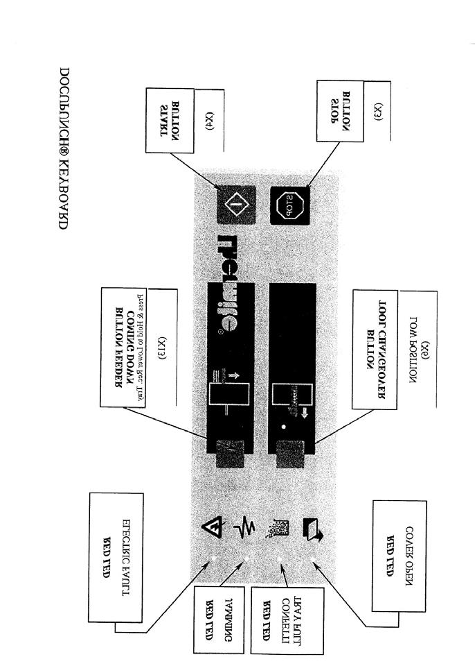
9 4) Operator Troubleshooting: If, after following the instructions in this section, the operator is unable to make the machine run correctly, it will be necessary to place a service call with whomever the machines was purchased from. A) If the machine jams with pins in paper, hold Stop key to reverse motor and clear the jam. (If pins are already up, nothing will happen when you press the stop key). B) If the machine will not turn on and/or run, check the following: 1) Are any of the LEDs on the control panel lit? If yes, see below. If not, see number 2 of this section. Electronic Fault: Make sure the emergency stop switch is pulled out. Make sure all of the covers are closed. Paper Jam: Make sure there is no paper caught anywhere in the machine. Make sure the sensors and the reflectors are clean. Confetti Tray: Make sure the confetti bin is empty. Make sure the sensor and the reflector are clean. Cover Open: Make sure all of the covers are closed. 2) Make sure the power cord is connected to both the machine and the 110V supply and that the main switch is in the ON position. 3) Make sure there is 110VAC present at the supply outlet. C) The machine will not feed paper: 1) With the machine running, make sure the stabber is moving in and out, and the pincher is moving up and down. 2) Make sure the belts are turning. 3) Make sure the backstop on the feeder is against the pile. Page 7
10 D) The machine jams repeatedly: 1) Make sure there are no obstructions in the paper path or the die. 2) Make sure the paper is within the operating specifications indicated in this manual on Page 5. 3) Make sure the machine is set up correctly for the size paper you are trying to punch. E) The ends of the paper are getting nicked : 1) Make sure the pin pulls for that size are pulled out. If there are no pin pulls for the size being punched, it may be necessary to disassemble the die and remove two pins. 2) Make sure the die is in the correct position as indicated by the instructions for tool changing on Page 7. F) The holes are not registering properly on the paper.: 1) Make sure all of the paper is the same size. 2) Follow the instructions for Machine Set Up on Page 7 to ensure the joggers are set correctly. G) The paper jams repeatedly at the reception: 1) Make sure the top reception guide is properly adjusted. 2) Make sure there is nothing to prevent the paper from falling into the reception properly. Page 8
11 5) Cleaning & Maintenance Daily Maintenance Confetti tray should be emptied as needed. To empty confetti tray: Pull the confetti tray towards you Empty the tray Re-position it and insert tray until it stops Weekly Maintenance Using a soft, clean rag: Wipe down the machine. Clean the lens of the cell located at the confetti tray level, the one under the tool and another under the reflector. Annual Maintenance (at the rate of 600,000 strokes) See the counter located inside the electric box Have a general inspection performed on the unit by a factory trained technician. *Routine maintenance is not covered under the warranty. Please note: If your tool reaches a million strokes or its perforations do not meet your requirements in terms of quality, feel free to contact James Burn International or your local dealer to sharpen or make a diagnostic check of this tool. Page 9
12 SECTION III: MECHANICAL 1) Calibration of the Side Guides: It will be necessary to calibrate the side guides and joggers if: The holes are being punched off center on the paper. The linkage that controls the side guides and joggers is disassembled for any reason. The belt that links the side joggers to the feed and reception guides is broken or removed. The side guides on the feeder and the reception must be set in relation to the lateral joggers, which in turn are set in relation to the die. To calibrate the side guides and joggers, follow the steps listed below. (Note: Make sure the timing is correct first. See pg. 27.) a) Install a die into the machine. b) Remove the right side cover, feeder guides, the front plate, reception guides, reception jogger, and the rear plate. c) Tighten the timing belt on the right side. d) Loosen the set screws on the two timing pulleys for the feeder guides and the reception guides. (Leave the screws on the lateral jog pulley tight.) e) Loosen the set screws on the locking collar in Figure 1 (pg. 13). f) Center the lateral joggers with the die by turning the threaded shafts independently of each other. (Use the hand wheel to adjust the right side jogger.) g) Once centered, tighten the set screws on the locking collar. Make certain that the lateral joggers are correct before setting the feed and reception guides. h) Make sure the joggers are in the open position. Measure from the inside of the right hand plate to the inside of the right hand lateral jogger. Using the hand wheel on the right side, set the jogger so that it is 3 from the plate (Figure 2, pg. 14). i) Loosen the set screws on the locking collar (Figure 3, pg. 15). Page 10
13 j) By turning the threaded shaft, set the right side feeder guide so that there is 3.25 from the inside of the right side plate to the inside of the feeder guide mounting block (Figure 4, pg. 16) k) Tighten the set screws on the timing pulley for the feed guides. l) Loosen the set screws on the locking collar (Figure 5, pg. 17). m) Set the right side reception guide mounting block (this will be on the left side as you face the reception) using the threaded shaft so that it is from the inside of the mounting block to the inside of the side plate (Figure 6, pg. 18). n) Tighten the set screws on the reception pulley. o) Follow these same procedures to set the left side guides for the feeder and reception. p) Tighten the set screws on all of the locking collars. * Double-check all of the settings. Page 11
14 Page 12
15
16 Page 14
17 Page 15
18 Page 16
19 Page 17
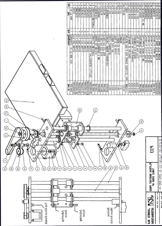
20 2) Feeder: The feeder tray on the DocuPunch uses a stepper motor to raise and lower the table. There is a micro switch at each end of the left assembly. The top switch sends a signal to the PLC when the tray reaches the top of its cycle. This tells the PLC that the tray is empty. The bottom switch tells the PLC when the tray has reached the end of its downward travel. The complete feeder assembly, including the micro switches and adjusting screws, is pictured on page 21. A) Adjusting the Top Micro Switch: *The top micro switch must be adjusted so that the machine does not stop cycling until it picks up the last sheet of paper. However, it must stop the machine before the feeder reaches its mechanical limit. 1) With the power on, press the Start button until the feeder begins to rise. When the machine begins to cycle, press the Stop button. 2) Turn the power off and remove the left side cover from the machine. 3) Turn the pulley on the top of the feeder to raise the feed tray, and stop when the top of the tray is about 1/16 higher than the tip of the stabber. 4) Loosen the lock nut on the actuating screw, and set the screw so that it just actuates the switch. 5) Tighten the lock nut. B) Adjusting the bottom micro switch: *The bottom micro switch must be adjusted so that the feeder cannot cycle down to its mechanical limit. 1) With the power on, press the feeder down button and allow the tray to cycle to the bottom. 2) Switch off the power and remove the left side cover. 3) Turn the timing pulley on the top of the feed assembly until the feeder reaches its mechanical limit. 4) Turn the pulley four turns in the opposite direction to raise the tray slightly. 5) Loosen the lock nut on the bottom actuating screw. 6) Adjust the screw so that it just actuates the switch and tighten the lock nut. Page 18
21 *To test, switch the power on and press the feeder down button. The feeder should cycle down and stop before it reaches its mechanical limit. Place a small amount of paper on the feeder, press the start button and punch the paper. The machine should cycle approximately 5 8 times after it lifts the last sheet of paper. Page 19
22 Page 20
23 3) Reception: A 24 VDC motor is used to move the reception tray up and down. The motor is controlled by the 24V relay card (see the electrical section of this manual). There is a microswitch at the bottom of the guide track that limits the downward motion of the tray. A sensor mounted at the top limits the upward movement and also sends a signal to the PLC as the tray fills with paper. 4) Pincher: The pincher is controlled by a solenoid, which gets a signal from the 24V relay card. The grip of the pincher must be adjusted properly in order for it to work correctly (the pincher must bottom out before the solenoid does). The procedure for adjusting the grip is as follows. a) Remove the left side cover from the machine. b) Loosen the clamping screw on the pincher shaft. c) Hold the pincher down against the BEC. d) Press the solenoid down until it bottoms out, then allow it to come back up approximately 1/64 1/32. e) Tighten the clamping screw. Page 21
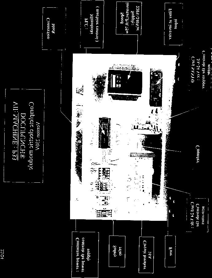
24 SECTION IV: ELECTRICAL 1) Fuses: QF1 Main supply 16A Circuit Breaker Upper Right in Electrical Panel F2 T1 SUPPLY 6.3A 5mm X 20mm (2 Fuses) Upper Right in Electrical Panel F4 Inverter Supply 10A 5mm X 20mm (2 Fuses) Upper Right in Electrical Panel FC1 24V Card (Supply) 16A 5mm X 20mm (2 Fuses) 24 V Relay Card FC2 PLC Supply 6A 5mm X 20mm 24 V Relay Card FC3 Foot Solenoid 3.15A 5mm X 20mm 24V Relay Card FC4 Counter 3.15A 5mm X 20mm 24V Relay Card FC5 Pincher Solenoid 3.15A 5mm X 20mm 24V Relay Card FC6 Feed Motor.25A 5mm X 20mm 24V Relay Card FC7 Fan 7.5A 5mm X 20mm 24V Relay Card FC8 Not used FC9 Reception Motor 5A 5mm X 20mm 24V Relay Card Page 22
25 2) Safety Circuit: The safety circuit consists of a relay that monitors the condition of the safety switches. When all of the switches are closed the relay will latch. This will send a signal to the PLC and also energize the main contractor. Below is a list of the switches and their locations. 1) Emergency Stop Right side cover 2) Top Perspex Guard Under Left Cover 3) Tool Guard Under Left Cover 4) Tool Lock Under Tool Guard 5) Tool Present Under Tool Guard If the emergency stop switch is pressed the Electronic Fault light on the control panel will come on. The guard switches each have two contacts (1 normally open and one normally closed). When a guard is opened, the N.C. contact will open the circuit to the safety relay, and the Electronic Fault light will come on. The N.O. contact will close to turn on the Cover Open light. The tool lock switch functions the same as the guard switches, except that the N.O. contact turns on the tool light on the control panel instead of the cover open light. The tool present switch functions the same, except that the contacts are reserved (the N.O. contact is in the relay circuit and the N.C. contact turns on the tool light). *To bypass the safety circuit, place a jumper wire between wire #601 & 204 on the safety relay. Page 23
26 3) Sensors: a) Feeder: (Input X5) This sensor is located under the right side cover. It sends a beam across the feed tray to read the top of the pile. b) Confetti tray: (Input X11) This sensor is located under the left side cover and sends a beam across the top of the tray to a reflector located under the right side cover. When this beam is blocked the confetti full light will come on. c) Paper Jam: (Input X7) This sensor is located directly in front of the die. It sends a beam down to a reflector to detect a paper jam. ** When adjusting the above sensors, you must position them so that the orange and green lights on them are lit. (The red light must not be lit.) d) Reception: (Input X10) This sensor is inductive and is located on the back of the rear cover. As the tray fills and the jogger is forced back a metal tab on the back of the jogger activates the sensor. 4) Encoder: The encoder monitors the position of the machine. It is supplied with 24VDC and sends information to the PLC via three channels. The supply can be checked by measuring voltage between the brown (+) and white (-) wires. Channels A & B can be checked by measuring between the green (Channel A, XO on PLC) or yellow (Channel B, X1 on PLC) and the white (-) wire. As the machine is turned the voltage will switch between channels as the encoder counts. The zero signal is sent via the gray wire. To check this signal, measure between the gray and white wires. Voltage should only be present when the encoder is at absolute zero. Page 24
27 5) Solenoids: There are two solenoids on the DocuPunch; one controls the pincher and the other controls the footstops. Both solenoids are identical and operate on 24 VDC. To check whether or not the solenoid is good, you must use an OHM meter to measure the resistance through the coil. You must first disconnect the solenoid, then measure between the two wires. The correct value of this measurement is 24 OHMS.(+ 2 OHMS) 6) Stepper Motor: The DocuPunch uses a stepper motor on the feeder to accurately control the amount of paper it lifts with each cycle. The motor is a 3AMP stepper with 1.8 degree steps. To check the stepper motor, cycle the feeder up to the top, then back down to the bottom. The motion should be very fluid, with no dead spots or jerky movements. Another check is to measure the resistance in the two windings on the motor. There should be 1.3 OHMS between the yellow and red wires, and also between the blue and orange wires. The motor is controlled by a stepper drive card. To check the card, measure the voltage between the four wires on the motor connector and wire #600 when the feeder is sitting idol. There should be 1.2 VDC at the yellow and orange wires, and 2.2 VDC at the red and blue wires. An output signal from the PLC is what tells the driver to run the motor. When output Y-0 is activated, the feeder should go up, and when both outputs Y-0 & Y-1 are activated, the feeder should go down. Page 25
28 SECTION V: TIMING There are two types of timing on the DocuPunch: Mechanical timing, which is adjusted by moving a series of cams and a timing belt, and electrical timing, which is adjusted by moving the position of the encoder on its shaft. Below is a list of the different functions, with the correct timing for each one. 1) 0 Degrees The input light X-2on the PLC should be on. 2) 226 Degrees The headstop should have just reached its down position. 3) 254 Degrees The reception jogger should be all the way up. 4) 259 Degrees The belt carriage should just start moving up. The stabber should just stop moving out. 5) 298 Degrees The lateral joggers should have just reached the closed position. If any of these settings are not correct, it will be necessary to adjust the timing. The procedure for setting the timing is as follows: 1) Mechanical Timing: 1) Remove the left side cover, feeder guides, front plate, reception guides, reception jogger and rear plate. 2) Using a 6mm hex key, turn the main pulley counter clockwise until the 259* mark is lined up with the left edge of the index tab. 3) Loosen the timing belt tensioner, and remove the belt from the stabber pulley. 4) Turn the stabber pulley counter clockwise and stop the instant that the stabber stops its outward motion. 5) Replace and tighten the timing belt. Be sure that neither the stabber pulley, or the main pulley lose their position as you tighten the belt. 6) Turn the main pulley counter clockwise until the 298* mark is lined up with the index tab. 7) Loosen the set screws on the stabber pulley. 8) Turn the top shaft counter clockwise until the lateral joggers just reach the closed position. 9) Tighten the set screws on the stabber pulley. 10) Turn the main pulley until the 226* mark lines up with the index tab. 11) Loosen the set screws on the headstop cam* and turn it counter clockwise and stop the instant the headstop reaches the down position. Page 26
29 12) Tighten the set screws on the cam. 13) Turn the main pulley until the 254* mark lines up with the index tab. 14) Loosen the set screws on the cam for the reception jogger and turn it counter clockwise. Stop when the follower arm reaches the top dead center of the cam. 15) Tighten the set screws. 16) Turn the main pulley until the 259* mark lines up with the index tab. 17) Loosen the four mounting screws from the belt carriage cam *. 18) Position the cam so that the belt carriage is at the very beginning of its upward motion. 19) Tighten the four mounting screws. *Please note: The cams for the headstop and belt carriage are mounted to the same sleeve. Once one is set correctly they both should be correct (unless one has been moved on the sleeve). 2) Electrical Timing: *The mechanical timing must be correct before setting the electrical timing. 1) Turn the main shaft counter clockwise until the 0* mark lines up with the index tab. 2) Loosen the set screws on the encoder collar. 3) Slowly turn the collar clockwise and stop when the input light X-2 comes on (this is the zero position on the encoder). 4) Tighten the screws on the encoder ensuring that the input light X-2 remains on. Double check this setting by turning the main pulley counter clockwise until the 0* mark is lined up with the index. At this point the input light for X-2 should be on. Page 27
30 SECTION VI TROUBLESHOOTING: 1) See Operator Troubleshooting (pgs. 9 10) before following these steps. The machine will not feed paper: A) Is the BEC moving in and out? If it is, move on to the next step. If not, check the following: 1) Check the timing belt. 2) Check the set screws on the pulley. B) Is the pincher solenoid working? If it is, make sure it is adjusted properly then move on to Step C. If not, check the following: 1) Check the solenoid. 2) Check to see if it is getting voltage from the relay card. 3) Check if the relay card is getting a signal from the PLC. C) Is the feed table moving up? If it is, move on to Step D. If not, check the following: 1) Check the stepper motor. 2) Check the stepper drive. 3) Check to see if the PLC is sending a signal to the stepper drive. Foot jogger will not operate: A) Check the solenoid. B) Check the jam sensor. C) Check the relay card. D) Check the output from the PLC. Machine will not run: A) Check the start button (Input X4). B) Check the inverter input from the PLC. C) Check the inverter supply. D) Check for fault lights on the control panel. Feeder will not come up: A) Check the sensor and reflector. B) Check the top microswitch. C) Check the stepper motor. D) Check the stepper drive. E) Check the relay card. F) Check the output from the PLC. Page 28
31 The feeder will not go down: A) Check the button. B) Check the bottom micro switch. C) Check the stepper motor. D) Check the stepper drive. E) Check the output from the PLC. The reception will not come up: A) Check the sensor and reflector. B) Check the output from the PLC. C) Check the output from the relay card. D) Check the motor. If the reception will not go down: A) Check the bottom micro switch. B) Check the output from the relay card. C) Check the output from the PLC. D) Check the motor. 2) Fault Lights: A) Electronic Fault: 1) Check the safety switches. 2) Check the die switches. 3) Check the emergency stop switch. 4) Check the safety relay. 5) Check the transformer. B) Paper Jam: 1) Check the sensor and reflector. 2) Check the PLC. C) Confetti Tray: 1) Check the sensor and reflector. 2) Check the PLC. D) Cover Open: 1) Check the safety switches. 2) Check the safety relay. E) Tool Light (machine will not start) 1) Check the die switches. Page 29
32 Page 30
33 OUTPUT LIST/PLC Y0 Pulses for stepper motor of feeder 24 Vcc Y1 Motor way on the feeder (coming down) 24 Vcc Y2 Counter + foot jogger 24 Vcc Y3 Pincher Solenoid Vcc Y4 Reception motor Vcc Y5 To reverse the motor Vcc Y6 Reverse rotation: jam punching Inverter Y7 1 st Speed (punching unit) Inverter Y10 2 nd Speed (punching unit) Inverter Y11 To validate rotation (+) Inverter Y12 Red LED : 3,5 V Jamming Y13 Red LED : 3,5 V Confetti Tray Y14 Green LED : 3,5 V Tool low position Y15 Green LED : 3,5 V Not Used Page 31
34 INPUT LIST/PLC X0 X1 X2 Encoder Way A Encoder Way B Encoder Zero Point X3 <<Stop>> Button B8 (605) X4 <<Start>> Button B1 (606) X5 Feeder Sensor C1 X6 <<Tool changeover>> Button BCO (608) X7 Detection at Tool Entry C2 X10 Detection Level Reception C4 X11 Confetti Tray C8 (611) X12 Inverter Alarm Switch Contact A et C X13 <<Going Down>> Button BRR (613) X14 Feeder High Position 601 C X15 Feeder Low Position 601 C X16 Full Table Tray (reception) R2 X17 Emergency Stop Button Page 32
35 Page 33
36 Page 34
37 Page 35
38 Page 36
39 Page 37
40 Page 38
41 Page 39
42 Page 40
ELECTRIC ACTUATOR HVAC/BAC ELECTRIC IOM. E024, EO25, E026, EO29 & E030 Installation Operation and Maintenance Instructions TABLE OF CONTENTS
 HVAC/BAC ELECTRIC IOM ELECTRIC ACTUATOR E024, EO25, E026, EO29 & E030 Installation Operation and Maintenance Instructions TABLE OF CONTENTS Electric Actuator Specifications... 2 Overview... 3 Actuator
MACHINE SENSORS CONTROL PANEL CONVEYOR SYSTEM SYSTEM SENSORS...
 TABLE OF CONTENTS TABLE OF CONTENTS... 1 CONTROL PANEL...... 4 MACHINE SENSORS... 5 CONVEYOR SYSTEM... 6 SYSTEM SENSORS... 6 INFEED BACKUP... 6 OUTFEED BACKUP... 6 CHANGEOVERS... 6 CONVEYOR GUIDES ADJUSTMENTS...
Electric Actuator Instructions
 BAC IOM Electric Actuator Instructions E024, E025, E026, E029 & E030 TABLE OF CONTENTS Electric Actuator Specifications...2 Overview...3 Actuator Wiring Diagrams...4 VMS-35 Specifications and Wiring Diagram...5
Setup and Programming Manual
 Microprocessor and Handy Terminal Setup and Programming Manual Versions U04 to U19 for Sliding Door Systems P/N 159000 Rev 7-2-07 The manufacturer, NABCO Entrances, Inc. suggests that this manual be given
Model 2300JL Installation Guide
 Model 2300JL Installation Guide POWER ACCESS CORPORATION 4 HERSHEY DRIVE, DOCK 4 ANSONIA, CT 06401 800-344-0088 WEBSITE: www.power-access.com EMAIL: salesinfo@power-access.com 1 STANDARD PARTS MODEL 2300JL
To Purchase This Item, Visit BMI Gaming
 Table of Contents General Operation. 3 How Slam-A-Winner plays How the Wheel Scores How the Ball Lift works Programming Options... 4-6 Troubleshooting Guide. 7-8 Parts Identification 9 Schematics 10-13
Reproduction or other use of this Manual, without the express written consent of Vulcan, is prohibited.
 SERVICE MANUAL ELECTRIC BRAISING PANS (30 & 40 GALLON) VE30 VE40 ML-126849 ML-126850 VE40 SHOWN - NOTICE - This Manual is prepared for the use of trained Vulcan Service Technicians and should not be used
ELECTRIC ACTUATOR 94OE IOM. E024, EO25, E026, EO29 & E030 Installation Operation and Maintenance Instructions TABLE OF CONTENTS
 ELECTRIC ACTUATOR E024, EO25, E026, EO29 & E030 Installation Operation and Maintenance Instructions TABLE OF CONTENTS 94OE IOM Electric Actuator Specifications...2 Overview...3 Actuator Wiring Diagrams...4
IMPORTANT! DO NOT THROW AWAY THE SHIPPING CARTON AND PACKING MATERIAL
 Operator s Manual IMPORTANT! DO NOT THROW AWAY THE SHIPPING CARTON AND PACKING MATERIAL ii Table of Contents Operator Safety... 1 Introduction... 2 Unpacking and Setup... 3 Unpacking... 3 Setup... 4 ROCKET
BR230 MOTORIZED VIP. OPERATION and MAINTENANCE MANUAL
 BR230 MOTORIZED VIP OPERATION and MAINTENANCE MANUAL 1 TABLE OF CONTENTS TURNSTILE SAFETY INSTRUCTIONS 3 TURNSTILE USER INSTRUCTIONS 3 BR230 MOTORIZED VIP TURNSTILE TECHNICAL SPECIFICATIONS 4 BR230 MOTORIZED
PRODUCT INFORMATION BULLETIN #3365 DIGITAL MOTOR CONTROL PLATTER SYSTEMS For Serial Number and After
 PRODUCT INFORMATION BULLETIN #3365 DIGITAL MOTOR CONTROL PLATTER SYSTEMS For Serial Number 28640996 and After Record Platter System Identification Numbers Here: Model # Serial # Table of Contents Program
Model 2300DL Installation Guide
 Model 2300DL Installation Guide POWER ACCESS CORPORATION 4 HERSHEY DRIVE, DOCK 4 ANSONIA, CT 06401 800-344-0088 WEBSITE: www.power-access.com EMAIL: salesinfo@power-access.com 1 STANDARD PARTS MODEL 2300DL
SERVICE MANUAL. Standard Horizon PF-P310 Paper Folder
 SERVICE MANUAL Standard Horizon PF-P310 Paper Folder Read this manual, and thoroughly familiarize yourself with its contents before operating or servicing this equipment. PF-P310/SM FOREWORD Paper Folder
Contents. Section 2: Electrical - Switches, Solenoids and Motors
 Contents Section 2: Electrical - Switches, Solenoids and Motors... 2-3 Switches... 2-3 Switches A, B, C and D... 2-4 Error Codes A Switch... 2-4 Error Codes B Switch... 2-4 Error Codes C Switch... 2-5
Z TECHNICAL INSTRUCTIONS
 ÍNDICE: Z40 2.0 TECHNICAL INSTRUCTIONS 1.- Error list 2.- Replace the control board 3.- Opening the machine 4.- Replace the power board 5.- Dismantling motor and gear box 6.- Assembly of gear box 7.- Pushing
icreaseexcel Digital Creaser Operators Manual
 2-2013 6-2013 Version 1.0 3.0 icreaseexcel Digital Creaser Operators Manual WWW.MBMCORP.COM 800-223-2508 TABLE OF CONTENTS SPECIFICATIONS.1a SAFETY PROCEDURES/CARE & MAINTENANCE..1b COMPONENT IDENTIFICATION
XR Conveyor Maintenance Guide
 XR Conveyor Maintenance Guide EN-0035 Rev. A XR Conveyor Maintenance Guide www.qdraw.com Table of Contents 05/20/2009 Overview Page 3 XR Conveyor Assembly Page 4 General Information Exploded View of an
JEEVES. JEEVES Installation Manual. Installation Manual The Easiest Do-It-Yourself Dumbwaiter on the Market
 1 888-323-8755 www.nwlifts.com JEEVES Installation Manual The Easiest Do-It-Yourself Dumbwaiter on the Market This manual will cover the installation procedure step-by-step. The installation of this dumbwaiter
OPERATING INSTRUCTIONS IC-2, 3,4,5,6 INTELLICUT SERVO CUTTER Version 5.1xx Created 11/2009
 OPERATING INSTRUCTIONS IC-2, 3,4,5,6 INTELLICUT SERVO CUTTER Version 5.1xx Created 11/2009 "CAUTION" "DO NOT OPERATE MACHINE WITH GUARD REMOVED" UNCRATE AND INSPECT This machine has been carefully crated
TECHNICAL SERVICE DEPARTMENT Technical Service Bulletin LowNOx Commercial Gas Electronic Spark Ignition Sequence
 The Universal TM gas LowNOx series water heaters contain an electronic spark ignition system. The heater is connected to a 120VAC power source required by the transformer. The transformer steps down the
INSTALLATION AND OPERATING INSTRUCTIONS
 ASTRO ENVELOPE FEEDER AMC-2000-5 FOR RYOBI 3302 / ITEK 3985 (2 COLOR) INSTALLATION AND OPERATING INSTRUCTIONS INTRODUCTION Thank you for purchasing the Astro Envelope Feeder. It is fast, efficient, reliable,
Service and Parts Manual. NO LONGER IN PRODUCTION Some service parts may not be available for this product. Otolaryngology Chair.
 thru 391-001 -002 Otolaryngology Chair Serial Number Prefixes: EN, PD & V Service and Parts Manual NO LONGER IN PRODUCTION Some service parts may not be available for this product. 391-001 thru -002 NOTE:
HD 7700 Setup & Operator Manual
 HD 7700 Setup & Operator Manual Issue 1 December, 01 Performance Design Inc. The Heavy Duty Ultima (HD 7700) electric punch has been designed to punch most any job that may pass through your bindery or
2020 Dual Tabber Operation Manual
 2020 Dual Tabber Operation Manual Revision 1.2 10 Clipper Road 10/24/2006 West Conshohocken, PA 19428-2721 Tel : 800-523-0320 / 610-825-6205 Fax: 610-825-1397 www.secap.com Index SECTION 1 Introduction
FD 120 Card Cutter MAINTENANCE MANUAL. MyBinding.com 5500 NE Moore Court Hillsboro, OR Toll Free: Local: /2011
 FD 120 Card Cutter 5/2011 MAINTENANCE MANUAL SAFETY PRECAUTIONS Always observe the cautions and warnings given below to prevent personal injury or property damage. The degree of danger and damage that
Installation and Service Manual
 RESIDENTIAL PLATFORM LIFTS RPL400 / RPL600 Installation and Service Manual WARNING! STRICT ADHERENCE TO THESE INSTALLATION INSTRUCTIONS IS REQUIRED to promote the safety of those installing this product,
Contents. Section 2: Electrical - Switches, Solenoids and Motors
 Contents Section 2: Electrical - Switches, Solenoids and Motors... 2-3 Switches...2-3 Switches A, B, C and D...2-4 Error Code A Switch...2-4 Error Code B Switch...2-5 Error Code C Switch...2-5 Error Code
Best Diversified Products, Inc. Product Manual. BestReach Rigid Belt. Models BRB 230 OS BRB 230 SS BRB 460 OS BRB 460 SS
 Best Diversified Products, Inc. Product Manual TM BestReach Rigid Belt Models BRB 230 OS BRB 230 SS BRB 460 OS BRB 460 SS Best Diversified Products Inc. 107 Flint Street Jonesboro, AR 72401 Phone 870-935-0970
Sofa Slideout Assembly OWNER'S MANUAL. Rev: Page 1 Sofa Slideout Owners Manual
 Sofa Slideout Assembly OWNER'S MANUAL Rev: 06.14.2016 Page 1 Sofa Slideout Owners Manual TABLE OF CONTENTS Warning, Safety, and System Requirement Information 3 Product Information 3 Prior to Operation
Automatic Sliding Door Retrofit Drive Assembly. Installation Manual DoorControlsUSA.com
 Automatic Sliding Door Retrofit Drive Assembly Installation Manual 800-437-3667 DoorControlsUSA.com TABLE OF CONTENTS pg. 1. COMPONENTS 2 2. HEADER PREPARATION 2 3. DOOR PREPARATION 2 4. MOTOR AND CONTROLLER
XPS-ProFeed Shuttle SERVICE MANUAL. Revised:
 XPS-ProFeed Shuttle SERVICE MANUAL Revised: 9-14-15 RENA SYSTEMS INC. 910 East Main Street; Suite 200 Norristown, PA 19401-4110 Phone: (610) 650-9170 Fax: (610) 270-3947 Web Site: www.renausa.com SAFETY
Some service parts may not be available for this product!
 -00 thru -00 Power Examination Table Service and Parts Manual Serial Number Prefixes: FA, FB NO LONGER IN PRODUCTION Some service parts may not be available for this product! -00 thru -00 FOR USE BY MIDMARK
Auto Sentry-eXP Maintenance. Revised 12/21/07
 Auto Sentry-eXP Maintenance Revised 12/21/07 Maintenance Procedures for Auto Sentry exp Bill Dispenser Credit Card Reader Bill Acceptor Bill Dispenser Maintenance Bill Dispenser Problem / Cause Bill Dispenser
Centrifuge Operator / Service Manual
 3000 Centrifuge Centrifuge Operator / Service Manual cat.# 26230 & 26231 The Q-sep 3000 centrifuge complies with all requirements of UL standard 3101 20, Can/CSA C22.2 No. 1010.1, and Can/CSA C22.2 No.
Table of Contents. General Operation. 3 How Slam-A-Winner plays How the Wheel Scores How the Ball Lift works Programming Options...
 61-MAN-B Table of Contents General Operation. 3 How Slam-A-Winner plays How the Wheel Scores How the Ball Lift works Programming Options... 4-6 Troubleshooting Guide. 7-8 Parts Identification 9 Schematics
Contents. Section 5: Adjustments Ball Detect Adjustment Transport Band Tension Adjustment
 Contents Section 5: Adjustments... 5-3 1. Ball Detect Adjustment... 5-3 2. Transport Band Tension Adjustment... 5-5 3. Transport Band Drive Belt Tension Adjustment... 5-7 4. Ball Cushion Adjustment...
Terminal Assembly Machine
 1996 Instruction/Service Manual Terminal Assembly Machine Acme Manufacturing Inc. #J9876 Built by: For: The Wiley Company ACME Manufacturing, Inc. 2000 Coyote Lane Roadrunner, MN 55122 (612) 555-1234 (612)
SUNROOF - SERVICE INFORMATION ADJUSTMENTS
 SUNROOF - SERVICE INFORMATION DESCRIPTION OPERATION DIAGNOSIS AND TESTING POWER TOP - SUNROOF SUNROOF ASSEMBLY-MODULE REMOVAL INSTALLATION CHANNEL-DRAIN REMOVAL INSTALLATION COVER-GUIDE MECHANISM REMOVAL
Connector Systems Inc. SS-20 MACHINE MANUAL
 Connector Systems Inc. SS-20 MACHINE MANUAL INTRODUCTION Your SS-20 machine comes to you fully equipped and set up to terminate the style of plug you have requested. Our SS-20N will accommodate those
Read Chapter 8 Servicing Machine in the Manual for general guidelines
 Page 1 of 6 Read Chapter 8 Servicing Machine in the Manual for general guidelines The PlasmaCAM will not work on a GFI circuit. Earth ground the grates of the PlasmaCAM. Computer Configuration A. PlasmaCAM
VOLUMETRIC BLENDING SYSTEM OPERATION MANUAL
 VOLUMETRIC BLENDING SYSTEM OPERATION MANUAL 12285 E. MAIN ST. MARSHALL, IL 62441 PHONE: 217-826-6352 FAX: 217-826-8551 WEB SITE: www.yargus.com 1 OPENING SCREEN The OPENING SCREEN is the screen that the
Detroit Speed, Inc. Electric Headlight Door Kit Corvette P/N: &
 Detroit Speed, Inc. Electric Headlight Door Kit 1968-82 Corvette P/N: 122006 & 122007 The Detroit Speed Inc. Electric Headlight Door Kit replaces the stock vacuum actuated system on all 1968-82 Corvettes.
CRESTLINE DAMPENING SYSTEM INSTALLATION INSTRUCTIONS. Ryobi 3302M Itek 3985 A.B. Dick 9985 X /99
 CRESTLINE DAMPENING SYSTEM INSTALLATION INSTRUCTIONS Ryobi 3302M Itek 3985 A.B. Dick 9985 X88-32 3/99 GENERAL INFORMATION ATTENTION CRESTLINE DAMPENER OWNER Accel Graphic Systems provides parts and service
FD 342 Document Folder
 FD 342 Document Folder 6/2010 OPERATOR MANUAL FIRST EDITION TABLE OF CONTENTS SUBJECT PAGE DESCRIPTION 1 SPECIFICATIONS 1 UNPACKING 2 SETUP 2 CONTROL PANEL 3 OPERATION 4 SETTING CUSTOM FOLDS 5 BATCH COUNTING
CERM Counter System troubleshooting
 CERM Counter System troubleshooting In this document, we will try to clarify different solutions for problems with the CERM Counter System after installation. Content Hardware modules (in the gray box)
T621 Repair Manual (Electronics)
") T621 Repair Manual (Electronics) Table of Contents 1-1-1. Product Picture-T621 1-2-1. Display-T621 1-3-1. Component Placement-T621 Display 1-3-2. Component Placement-T621 Drive Board Area 1-4-1. Block
T621 Repair Manual (Electronics) Table of Contents 1-1-1. Product Picture-T621 1-2-1. Display-T621 1-3-1. Component Placement-T621 Display 1-3-2. Component Placement-T621 Drive Board Area 1-4-1. Block
Sure-Feed Engineering Inc. SE-900-EI. Operation & Parts Manual
 . SE-900-EI Operation & Parts Manual SE 900 EI OWNERS MANUAL Table of Contents 1. Installation guide 2. Set-up instructions 3. Operation instructions 4. Cleaning 5. Troubleshooting 6. Parts manual 7. Electrical
Contents. Overview Pinsetter Orientation...1-4
 Contents Overview...1-3 Pinsetter Orientation...1-4 Pinsetter Description...1-5 Ball Pit...1-5 Ball Cushion...1-5 Transport Band...1-7 Ball Accelerator...1-8 Pin Elevator...1-10 Distributor...1-14 Setting
Perfmaster Air V3. Serial Number. Date
 Perfmaster Air V3 12-2015 Serial Number Date TABLE OF CONTENTS SPECIFICATIONS.3 SAFETY PROCEDURES/CARE & MAINTENANCE..4 COMPONENT IDENTIFICATION 5 DELIVERY TRAY ASSEMBLY.6 PAPER STOP ASSEMBLIES..7 MACHINE
SE-1200-IJ ECO - SERIES. Operation & Parts Manual
 SE-1200-IJ ECO - SERIES Operation & Parts Manual SE 1200 IJ ECO - SEREIS OWNERS MANUAL Table of Contents 1. Installation guide 2. Set-up/operation instructions 3. Cleaning 4. Troubleshooting 5. Parts manual
Detroit Speed, Inc. Electric Headlight Door Kit Corvette P/N: &
 Detroit Speed, Inc. Electric Headlight Door Kit 1968-82 Corvette P/N: 122006 & 122007 The Detroit Speed Inc. Electric Headlight Door Kit replaces the stock vacuum actuated system on all 1968-82 Corvettes.
RE Generation II Troubleshooting Guide Section I Preliminary Information and Evaluation
 DODGE ENGINEERING & CONTROLS, INC. 196 Riverneck Road Chelmsford, MA 01824 PHONE (978) 244-1200 FAX (978) 244-1422 TOLL FREE (877) 334-2875 RE Generation II Troubleshooting Guide Section I Preliminary
BestReach Rigid Roller Drive-Out Conveyor System
 BestReach Rigid Roller Drive-Out Conveyor System Operator s Manual FMH Conveyors LLC p. 800.327.9209 Part Number 99038 107 Flint Street t. 844.FMH.SERVICE Effective June 2016 Jonesboro, AR 72401 f. 870.935.3661
RODIX, INC. FC-40-PLC Plus Series Control Troubleshooting Guide for Circuit Board P/Ns and
 RODIX, INC. FC-40-PLC Plus Series Control Troubleshooting Guide for Circuit Board P/Ns 24-488 and 24-489 Control must be connected to a known GOOD LOAD prior to testing Problem: No output from the control
Model H/HB Heavy-Duty Industrial Drawbar Door Operator Safety, Installation and Service Manual
 Model H/HB Heavy-Duty Industrial Drawbar Door Operator Safety, Installation and Service Manual OSCO requires use of an electric edge or photoelectric control for pedestrian protection on all automatic
Legacy Installation Manual
 Staying Home Corporation 1503 Vine Street P.O. Box 37 3823 Harrisonville, MO 64701 816.380.2427 Asheville Hwy. Hendersonville, www.stayinghome.com NC 28791 Precision Stairlifts Mailing Address: 306 Number
SE-600-P Eco-Series. Operation & Parts Manual
 SE-600-P Eco-Series Operation & Parts Manual SE 600 PC & PS SERIES OWNERS MANUAL Table of Contents 1. Set-up instructions 2. Bridge-Tramming Procedure 3. Operation instructions 4. Cleaning 5. Troubleshooting
HP21 SERVICE SUPPLEMENT UNIT INFORMATION. TSC6 Two-Speed Control
 SERVICE UNIT INFORMATION SUPPLEMENT HP21 Corp. 9426 L10 Litho U.S.A. All HP21-4 and -5 units (single and three phase) are equipped with a TSC6 two-speed control. The TSC6 (A14) two-speed control contains
AIR CLEANERS Model MC 3000 OWNER S MANUAL CAUTION Read complete instructions before operating. Please file for future reference.
 AIR CLEANERS Model MC 3000 OWNER S MANUAL CAUTION Read complete instructions before operating. Please file for future reference. MODEL MC 3000 SPECIFICATION Input Volts: 208-230/430 VAC, 60Hz, 3 Phase
Troubleshooting Bosch Proportional Valves
 Troubleshooting Bosch Proportional Valves An Informative Webinar Developed by GPM Hydraulic Consulting, Inc. Instructed By Copyright, 2009 GPM Hydraulic Consulting, Inc. TABLE OF CONTENTS Bosch Valves
EB Conveyor Maintenance Guide
 EB Conveyor Maintenance Guide EN-0037 Rev A EB Conveyor Maintenance Guide www.qdraw.com Table of Contents Overview Page 3 Exploded View Of A Standard EB Conveyor Page 4 Preventative Maintenance Page 5
2. Fault Code Procedures
 2. Fault Procedures Section Contents Page Introduction.......................2-3 Section 2 Entry Flow Chart...........2-4 Paper Jam Entry Flow Chart..........2-5 Status Fault s Table 1. Status Entry Table
Installation & Service Manual
 Installation & Service Manual for M² Sync Slideout Control Box #1510000122 CONTENTS Introduction Installation Installation Problems Program Mode Operation Mode Preventative Maintenance Fault Diagnostics
materials and workmanship for 2 years. Should the centrifuge require warranty or Phone: or Fax:
 WARRANTY The Drucker Company warranties that this centrifuge is free from defects in materials and workmanship for 2 years. Should the centrifuge require warranty or out-of-warranty service please contact:
Retro it Steering Column
 Retro it Steering Column INSTALLATION INSTRUCTIONS for 1976-86 CJ5 & CJ7 FOR PART NUMBER S: 1520800010, 1520800020, 1520800051, 1526800010, 1526800020, 1526800051 S I NCE 1986 Instruction # 8000000010
Heavy Duty Miniature Quick-Change Applicator (Side-Feed Type) with Mechanical or Air Feed Systems
 with Mechanical or Air Feed Systems") Heavy Duty Miniature Quick-Change Applicator (Side-Feed Type) with Mechanical or Air Feed Systems Instruction Sheet 408-8040 30 NOV 17 Rev H Ram Assembly Ram Post Locking Screw Stock Drag Drag Release
Heavy Duty Miniature Quick-Change Applicator (Side-Feed Type) with Mechanical or Air Feed Systems Instruction Sheet 408-8040 30 NOV 17 Rev H Ram Assembly Ram Post Locking Screw Stock Drag Drag Release
OPERATING INSTRUCTIONS FOR. Gold-Place TM. Manual Pick & Place with Dispenser System Model MPP-21
 OPERATING INSTRUCTIONS FOR Gold-Place TM Manual Pick & Place with Dispenser System Model MPP-21 AUTOMATED PRODUCTION SYSTEMS, INC. 2840 Pine Road Huntingdon Valley PA 19006 Phone: (215) 938-1000 FAX: (215)
 Page 1 of 29 Section 04-05: Suspension, Computer Controlled 1997 Town Car Workshop Manual DIAGNOSIS AND TESTING Procedure revision date: 05/16/2000 Suspension, Computer Controlled Inspection and Verification
XPS-ProFeed Shuttle SERVICE MANUAL. Revised:
 XPS-ProFeed Shuttle SERVICE MANUAL Revised: 1-14-15 RENA SYSTEMS INC. 910 East Main Street; Suite 200 Norristown, PA 19401-4110 Phone: (610) 650-9170 Fax: (610) 270-3947 Web Site: www.renausa.com SAFETY
OPERATING & SERVICE PARTS MANUAL SM20ES ENERGY SMART WRAPPER
 OPERATING & SERVICE PARTS MANUAL SM20ES ENERGY SMART WRAPPER Series B Model SM20ESC6 Cradle Mount Model SM20ESC6 Cradle Mount Shown with Optional Left & Right Wings Model SM20ESC6 Cradle Mount Shown with
INSTALLATION AND OPERATING INSTRUCTIONS
 ASTRO ENVELOPE FEEDER AMC-2000 INSTALLATION AND OPERATING INSTRUCTIONS INTRODUCTION Thank you for purchasing the Astro Envelope Feeder. It is fast, efficient, reliable, and designed to provide many years
OPERATING & SERVICE PARTS MANUAL 700ES ENERGY SMART WRAPPER SERIES B
 OPERATING & SERVICE PARTS MANUAL 700ES ENERGY SMART WRAPPER SERIES B READ ALL INSTRUCTIONS CAREFULLY BEFORE OPERATING EQUIPMENT TABLE OF CONTENTS Machine Components & Electrical Requirement... 3 Preliminary
METROLOGIC INSTRUMENTS, INC. MX001 Industrial Control Interface Installation and User s Guide
 METROLOGIC INSTRUMENTS, INC. MX001 Industrial Control Interface Installation and User s Guide Copyright 2007 by Metrologic Instruments, Inc. All rights reserved. No part of this work may be reproduced,
TM-1620 OPERATING INSTRUCTIONS AND OWNERS MANUAL
 TM-1620 OPERATING INSTRUCTIONS AND OWNERS MANUAL tracopackaging.com 800-284-WRAP 620 SOUTH 1325 WEST OREM, UT. PHONE 800-284-WRAP (9727) IMPORTANT: READ ALL INSTRUCTIONS BEFORE OPERATING EQUIPMENT Your
Sterling Coilmaster JR TS Issue 3 July 2017
 Sterling Coilmaster JR TS Issue 3 July 2017 CMjr TS Operator s Training Manual Issue 3 1 P a g e 1. Important Safety Notice!...3 2. Placing the CMjr in the Proper Location...4 3. Preparing the CMjr for
632 Western Avenue Henniker, New Hampshire Tel. (603) Fax (603) POSITION OF THE ROLLER PLATES
 Fax (603) POSITION OF THE ROLLER PLATES") POSITION OF THE ROLLER PLATES The roller plate must be positioned as shown. The measurement to both of the roller plates is taken from the face of the kingpin shaft to the inside edge of the roller wheel
POSITION OF THE ROLLER PLATES The roller plate must be positioned as shown. The measurement to both of the roller plates is taken from the face of the kingpin shaft to the inside edge of the roller wheel
CENTRIFEEDER ELECTRONICS
 CENTRIFEEDER ELECTRONICS FOR USE WITH CENTRIFEEDER with Integrated Vibratory Control REV 08/13 ADDENDUM VERSION 6.22 SOFTWARE Copyright 2011 Eastern Instrument Laboratories, Inc. All Rights Reserved. TABLE
OnCommand Troubleshooting Guide Hayward Industries
 OnCommand Troubleshooting Guide 2010 Hayward Industries Table of Contents Safety Precautions Page 1 Overview Pages 2-5 Software Troubleshooting Page 6 Local Display Pages 7-8 Relays Pages 9-10 Heaters
SE-1200-MP ECO - SERIES
 Inc. SE-1200-MP ECO - SERIES Operation & Parts Manual SE 1200 MP ECO -SERIES OWNERS MANUAL Table of Contents 1. Installation guide 2. Set-up instructions 3. Operation instructions 4. Cleaning 5. Troubleshooting
Stir-Guard Operation. Instructions Design III Stir-Guard Option
 1004 East Illinois Street Assumption, IL 62510 1-217-226-4421 Stir-Guard Operation Instructions Design III Stir-Guard Option The Stir-Guard is designed to protect the grain by shutting off the Stir-Ator
Induction Power Supplies
 Induction Power Supplies 7.5kW; 135 400kHz 480V version (Integral Heat Station) User s Guide Model 7.5-135/400-3-480 SMD Control Brds Rev. D 5/08 Table of Contents 1. Specifications and features...3 2.
ASVC2 OWNER S MANUAL. Vane Cutter PART # MACHINERY DIVISION
 A S ASVC2 Vane Cutter PART # 43013 MACHINERY DIVISION OWNER S MANUAL -1- INTRODUCTION The ASVC2 Hollow Vane Cutting Machine was designed utilizing the best current technology to provide greater reliability.
,IWKHUHDUHDQ\TXHVWLRQVFRQWDFW6WHIIHV&RUSRUDWLRQ 7HFKQLFDO6XSSRUWDW67())(6
)(6") 9 7528%/(6+227,1* *8,'( )255220+($7,1*81,76 02'(/6 (;7(;7(;7 (;7 (;7 35()$&( 7KLVJXLGHFRQWDLQVLQVWUXFWLRQVIRUWURXEOHVKRRWLQJWKH6WHIIHV &RUSRUDWLRQURRPKHDWLQJXQLWV0RGHOV(;7,QFRPSLOLQJWKLVJXLGH6WHIIHV&RUSRUDWLRQKDVXVHGLWVEHVWMXGJHPHQW
9 7528%/(6+227,1* *8,'( )255220+($7,1*81,76 02'(/6 (;7(;7(;7 (;7 (;7 35()$&( 7KLVJXLGHFRQWDLQVLQVWUXFWLRQVIRUWURXEOHVKRRWLQJWKH6WHIIHV &RUSRUDWLRQURRPKHDWLQJXQLWV0RGHOV(;7,QFRPSLOLQJWKLVJXLGH6WHIIHV&RUSRUDWLRQKDVXVHGLWVEHVWMXGJHPHQW
Installation Instructions Jeep CJ-7
 Retrofit Steering Column Installation Instructions 1976-86 Jeep CJ-7 For Part # s 1520800010, 152800020, 1520800051 www.ididitinc.com 610 S. Maumee St., Tecumseh, MI 49286 (517) 424-0577 (517) 424-7293
Name: ACORN Inc. Address: 6450 Kingspointe Parkway, Unit 1, Orlando, Florida, IMPORTANT!
 MANUFACTURER INFORMATION: Name: ACORN Inc. Address: 6450 Kingspointe Parkway, Unit 1, Orlando, Florida, 32819 Helpline: 407 650-0216 IMPORTANT! READ THESE PROCEDURES THOROUGHLY PRIOR TO stair lift INSTALLATION
Operating & Maintenance Instructions Thermobend Elite Range
 Operating & Maintenance Instructions Thermobend Elite Range Table of Contents 1. Setting Up... 2 1.1 Introduction... 2 1.2 Location & Assembly... 4 1.3 Electrical Supply & Connection... 5 1.4 Pneumatic
SECTION B1: MACHINE COMPONENTS
 SECTION B1: MACHINE COMPONENTS The machine portion of the Injected Metal Assembly system provides the means for: holding, heating and injecting the alloy; distributing and controlling electrical, pneumatic,
Sure-Feed Engineering Inc. PLACER STANDARD HOPPER. Operation & Parts Manual PLACER-STD_1
 Engineering Inc. PLACER STANDARD HOPPER Operation & Parts Manual PLACER-STD_1 Engineering Inc SECTION 2 PLACER OWNERS MANUAL Table of Contents 1. Installation guide 2. Set-up/operation instructions 3.
CABINET REEL OPERATING INSTRUCTIONS
 CABINET REEL OPERATING INSTRUCTIONS MODELS 15, 25, 40 & 60 SERIES RAPID-AIR CORPORATION 4601 KISHWAUKEE ST. ROCKFORD, IL 61109-2925 Phone: (815) 397-2578 Fax: (815) 398-3887 Web Site: www.rapidair.com
LIPPERTCOMPONENTS, INC.
 LIPPERTCOMPONENTS, INC. SCHWINTEK INWALL SLIDEOUT SYSTEM OPERATION AND SERVICE MANUAL Contents I. Controls 1-1 System components 1 1-1A versions C1 & C2 2 1-2 Motor wiring harness connections 3 1-3 Extend
#92 DISC BRAKE ADJUSTMENTS # BRAKE MONITOR
 #92 DISC BRAKE ADJUSTMENTS #102-091 BRAKE MONITOR Page 1 of 11 HOLLISTER-WHITNEY DISC BRAKE WITH BRAKE MONITOR ADJUSTMENT PROCEDURE Page 2 of 11 HOLLISTER-WHITNEY DISC BRAKE WITH MONITOR SWITCH ADJUSTMENTS
Three Function Remote Control System with Alarm (Model RCA-3)
") Golden RODtronics P.O. Box 146 Golden Colorado 80402-0146 Phone 303-423-8597 Fax 303-420-4575 Three Function Remote Control System with Alarm (Model RCA-3) Congratulations! You have just purchased one
Golden RODtronics P.O. Box 146 Golden Colorado 80402-0146 Phone 303-423-8597 Fax 303-420-4575 Three Function Remote Control System with Alarm (Model RCA-3) Congratulations! You have just purchased one
6204 Series Low-Volume Inserter
 204 Series Low-Volume Inserter /2012 MAINTENANCE MANUAL Mechanical description Mechanical description...51 General...52 Covers and plates...52 Electrical components...57 Feeder modules...0 Document feed...4
Illustrated Parts List
 Illustrated Parts List. Ordering Parts For your convenience, replacement parts and accessories can be ordered from ARPAC by fax 24 hours a day. Please have the following information available to ensure
BOXER KING 5600/5600R TRUCK TYRE CHANGER
 Author Stefano Muzzioli BOXER KING 5600/5600R TRUCK TYRE CHANGER SERVICE MANUAL 1 UPDATING GUIDE: Release B of 02/04/2010 Removed 50 or 60 Hz At page 49 2 TABLE OF CONTENTS 1.0 Introduction Pag. 5 2.0
Tooling Assistance Center
 Safeguards are designed into this application equipment to protect operators and maintenance personnel from most hazards during equipment operation. However, certain safety precautions must be taken by
C. Figure 1. CA-16 Front View Figure 2. CA-16 Rear View
 Figure 1. CA-16 Front View Figure 2. CA-16 Rear View 2 2.1. Restraint Elements Each restraint element consists of an E laminated electromagnet with two primary coils and a secondary coil on its center
Opera ons & Parts Manual VersaClipper 3100
 Opera ons & Parts Manual VersaClipper 3100 Heavy Duty Servo Driven & Computer Controlled Fully Automa c and Highly Versa le Clip A aching Machine Model #3100 Serial # 1 Revised 09/21/17 Table of Contents
Maintenance Information
 Form 16575334 Edition 1 April 2005 Electric Screwdrivers EL, EP and ET 34V DC Series Maintenance Information Save These Instructions WARNING Maintenance procedures have the potential for severe shock hazard
CAUTION -TABLE OF CONTENTS- II. OPERATING INSTRUCTIONS
 -PRINT- -TABLE OF CONTENTS- II. OPERATING INSTRUCTIONS his chapter contains safety precautions, daily safety check instructions, control and indicator descriptions, and operating instructions that apply