Table of contents. Game Play. Game Set-up. Technical Description. Programming. Error Codes. Electronic Components. Game Specifications.
|
|
|
- Benedict Grant Snow
- 5 years ago
- Views:
Transcription


1

2 Table of contents Game Play Game Set-up Technical Description Programming Error Codes Electronic Components Game Specifications Parts 2

3 Red Hot X-Treme 7s Game Play The object of Red Hot X-Treme 7s is to time the ball drop button press so that the 7 balls fall into the Red Hot slots on the wheel. Fill all 7 slots wins the jackpot. Filling less than 7 Red Hot slots pays out from tickets depending on the number of slots filled. See table below for ticket payout. In addition to the Red Hot slots there are blue Mystery Bonus slots, landing in one of these pays out a Mystery Bonus from in addition to how many Red Hot slots that were filled Number of Red Hots filled Tickets Dispensed 1 Red Hot 8 2 Red Hots 12 3 Red Hots 20 4 Red Hots 40 5 Red Hots 60 6 Red Hots Red Hots Jackpot Value LED Lighting The Red Hot X-Treme 7s utilizes low voltage (12v) LED lighting throughout the game for general illumination and accents. The Red hot X-Treme 7s also has a secondary power supply that runs most of its LED lighting. 12v LED light Secondary power supply 3


4 Game Assembly Red Hot base Red hot Wheel Assembly Support Pipes 1. Cut the plastic and remove the support pipes boxes 2. Remove pipes from boxes 4
")

5 3. Remove the Red Hot Wheel from box (Wheel is very heavy) 4. Lay Red Hot Wheel on back off the ground (Wheel is very heavy) Wheel Supports 5. Remove Red Hot Wheel shipping supports, saving bolts, as they will be used later to attach the wheel to the base. 5


6 6. Remove Red Hot base from box 7. Slide wheel support pipes into Red Hot base 6


7 8. Place a piece of foam from the shipping box onto the Red Hot Base. 9. With two people, lift the Red Hot Wheel and place on foam against the support pipes. Hold it there Now attach the wheel to the support pipes with the bolts from the shipping supports, starting with the top. 7

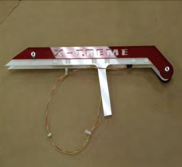
8 11. Cut the plastic wrap holding the light strips so that they hang. 12. Attach the trim pieces using the hardware provided. There are 3 screws for each pieces of trim. 8


9 13. Slide the light strips along the wheel and snap the tabs into the holes in the trim 14. Connect the Red Hot Wheel wires to the connecters on the Red Hot Base. 15. Connect to power source 16. Load ticket dispensers 9

 controls a stepper motor that rotates the wheel.")
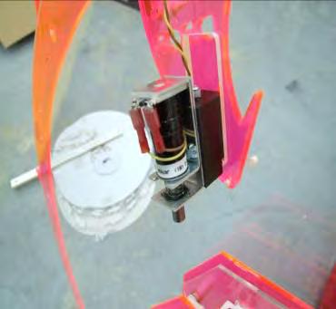
10 Technical Operation Stepper Controller Board Wheel Position Wheel position in Red Hot X-Treme 7s is determined by an optical sensor that communicates with the CPU board. The CPU receives a HOME signal from an optical sensor located behind the wheel. There is a pin inserted into the wheel and when the pin passes thru the optical sensor it blocks the beam then the sensor sends a signal to the CPU telling it that it has detected HOME pin. This HOME signal lets the CPU know the exact position of the wheel. A stepper controller board (SCB) controls a stepper motor that rotates the wheel. The wheel rotation is broken up into many Steps and the CPU counts these steps. Because the CPU knows where the HOME position is and it s counting every step it knows exactly where the wheel is at any time. Optical Sensors Scoring- ball sensor There is an optical transmitter located on the left side of the wheel that transmits a beam through the holes in the wheel and a receiver behind the wheel that detects the beam. When a ball falls into a slot it blocks the optical beam and its position is sent to the CPU. Since we know the position of the wheel at all times we can identify each hole and know it is a RED HOT or a MYSTERY BONUS hole. The CPU counts how many RED HOT or MYSTERY BONUS balls a player has and awards the corresponding number of tickets The Red Hot X-Treme 7s has a secondary power supply which powers most of the LED lights throughout the game. Optical Receiver Home Optical 10
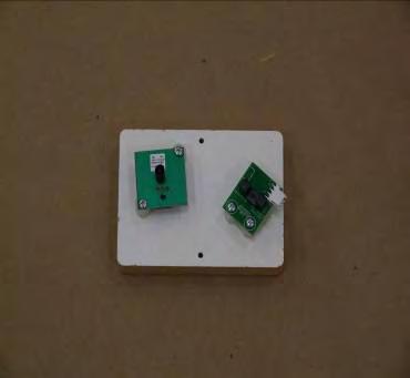
11 Programming the Red Hot X-Treme 7 s Game 1.) Entering Programming Mode To enter program mode, press and hold the right button located on the Power Distribution Board. After 2 seconds, TOTALS will appear on the LCD Display. At this time, release the button. COINS IN with the number of coins received will be displayed. The game is now in Program Mode. PLEASE NOTE that from this point forward, the right (Button 1) and left (Button 2) buttons on the Power Distribution Board are the buttons used. Each programming option is displayed on the LCD Display (located in the lower cabinet at the rear of the cashbox enclosure), with the functions shown for Buttons 1 and 2. 2.) COINS IN The total coins received through the coin mechanisms are displayed. The total will rollover to zero when it reaches 1,000,000,000. Depressing button 2 will display TICKETS OUT. 3.) TICKETS OUT The total tickets dispensed are displayed. The total will rollover to zero when it reaches 1,000,000,000. Depressing button 2 will display CLEAR G1 TICKETS OWED?, and/or CLEAR G2 TICKETS OWED? or "ENTER PROGRAMMING MODE?". 4.) CLEAR TICKETS OWED? This option is displayed only if there are tickets that are owed that have not been dispensed, and will show the number of tickets. Depressing Button 1 will clear these tickets from the system, and TICKETS CLEARED will be displayed. This option will be shown for each game separately. Depressing Button 2 will display ENTER PROGRAM MODE? 5.) ENTER PROGRAM MODE? Depressing Button 1 at this time will enter the area of Program Mode where parameters may be changed. Depressing Button 2 will return the game to Run Mode. 6.) ENTER PASSCODE To be able to change programming parameters or reset the counters, a 4-digit passcode must be entered. The default passcode is To enter the passcode, Depress Button 1 to change the digit from 0 to 9, then press Button 2 to move to the next digit. After all digits have been entered correctly, depressing button 2 will Display the first programming option, CHANGE PASSCODE?. 11
12 7.) CHANGE PASSCODE? Depressing Button 1 will allow for changing the passcode. Depressing Button 2 will move to DISPLAY CONTRAST. IMPORTANT!!! ONCE THE PASSCODE IS CHANGED, THE DEFAULT OF 0000 WILL NO LONGER WORK! BE SURE TO SAVE THE PASSCODE IN A SAFE PLACE! Entering the new passcode is accomplished in the same way that entering the passcode is done, as explained in 6.). 8.) DISPLAY CONTRAST This option sets the contrast for the LCD Display. Depress and hold Button 1 until the desired contrast is reached, then release Button 1. Depressing Button 2 will move to the next option, PLAY MODE VOLUME. 9.) PLAY MODE VOLUME This option sets the speaker volume during game play. When this option is entered, the game s background music will play continuously. Depressing Button 1 will increase/decrease the volume. As long as Button 1 is depressed, the volume will increase until the maximum is reached, then decrease until the volume is off. Depress and hold Button 1 until the desired volume is reached. Releasing Button 1 at any time and then depressing it again will change the direction of the volume adjustment. Depressing Button 2 will display the next option, ATTRACTION MODE VOLUME. 10.) ATTRACTION MODE VOLUME This option sets the speaker volume during Attraction Mode. When this option is entered, the game s background music will play continuously. Depressing Button 1 will increase/decrease the volume. As long as Button 1 is depressed, the volume will increase until the maximum is reached, then decrease until the volume is off. Depress and hold Button 1 until the desired volume is reached. Releasing Button 1 at any time and then depressing it again will change the direction of the volume adjustment. Depressing Button 2 will display the next option, JACKPOT MODE VOLUME. 11.) JACKPOT MODE VOLUME This option sets the speaker volume during a Jackpot Event. When this option is entered, the game s background music will play continuously. Depressing Button 1 will increase/decrease the volume. As long as Button 1 is depressed, the volume will increase until the maximum is reached, then decrease until the volume is off. Depress and hold Button 1 until the desired volume is reached. Releasing Button 1 at any time and then depressing it again will change the direction of the volume adjustment. Depressing Button 2 will display the next option, ATTRACTION FREQUENCY. 12
13 12.) ATTRACTION FREQUENCY This option sets the frequency at which the attraction mode occurs. The settings are from OFF to every 30 minutes. Depressing Button 1 will change the settings in 1- minute increments from OFF to 30 minutes, then back to OFF. Depressing Button 2 displays the next option, COINS PER CREDIT. 13.) COINS PER CREDIT This option sets the number of coins required for a credit. The settings are from 1 to 8 coins per credit. Depressing Button 1 will change the setting from 1 to 8, then back to 1. Depressing Button 2 displays the next option, JACKPOT INCREMENT 14.) JACKPOT INCREMENT Every time a credit is logged onto the game, the jackpot value is incremented by this amount. The setting is from 1 to 20 in increments of 1. Depressing Button 1 will change this setting from 1 to 20, and then revert back to 1. Depressing Button 2 will display the next option, JACKPOT TYPE. 15.) MERCY TICKET This option sets the Mercy Ticket Option to On or Off. Depressing button 1 will change the setting. Depressing Button 2 displays the next option, "WHEEL SPEED" 16.) WHEEL SPEED This option changes the speed of the wheel. Depressing button 1 will change the setting from 1(slowest) to 5(fastest). Depressing Button 2 displays the next option, "DISPLAY TICKETS OWED". 20.) DISPLAY TICKETS OWED If this option is turned on, tickets that are won are displayed and counted down on the Jackpot Display. If there are no tickets to be paid out, then the Jackpot Value is displayed. If this option is turned off, then only the Jackpot Value is displayed. Depressing Button 1 will change this option. Depressing Button 2 will enter the Resetting Totals Section. 21.) RESETTING TOTALS The totals displayed at the beginning of Program Mode (COINS IN, TICKETS OUT) and NUMBER OF JACKPOTS may be reset to zero here. The total number for each will be displayed. Depressing Button 1 will clear the total, and zero will be displayed, confirming that the count has been cleared. Depressing Button 2 will display the next 13
14 total. Depressing Button 2 after all of the totals have been displayed will display the next option, ENTER PROGRAM MODE? 22.) ENTER PROGRAM MODE? This option gives the opportunity to re-enter program mode if it is necessary to change any options again. Depressing Button 2 leaves Program Mode and the game returns to normal, Run Mode. ERROR CODES E-1 BALL SENSOR ERROR E-2 HOME SENSOR ERROR E-3 TICKET ERROR DEFAULT SETTINGS (ALL PAYOUT TABLES) PASSCODE 0000 PLAY MODE VOLUME 21 ATTRACTION MODE VOLUME 42 JACKPOT MODE VOLUME MAX ATTRACTION FREQUENCY 5 Minutes COINS PER CREDIT 1 JACKPOT INCREMENT 5 MERCY TICKET 0FF WHEEL SPEED 1 DISPLAY TICKETS OWED ON 14


 Power Distribution Board")


15 Electronic Components Electronics Assembly Hi Current Driver Stepper Controller Audio Board CPU Board Power Distribution board Power Supply Power Supply (lights) Power Distribution Board LED Indicators LEDs should be ON when game is powered up. They identify which voltages are present LEDs should normally be OFF. If ON they indicate an overload on the indicated voltage J1 Power IN J2 Power OUT 15


16 Electronic Components CPU J4 485 Serial Connector J3 Stepper LED Chart CPU LED Flashes = OK 5V ON = 5v HOME ON but dim J2 J1 Stepper Controller Board CPU LED Chart CPU LED Flashes = OK 5V LED ON = 5v 24V LED ON = 24v Switch Settings All Switches OFF J1 RS 485 Termination Jumper No Jumper Required J2 16

17 Electronic Components High Current Driver PCB J2 Inputs J1 Outputs Power LED LEDs turn ON only when the output is active Game Specifications Key numbers Weight Dimensions-set-up H W D Power consumption Fuses 2-5 amp in power supply F5L 250 volt FB Ticket dispensers 2 Benchmark Intelli triple Ball- Number/Size 7 17


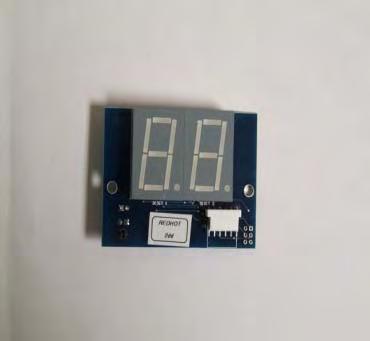
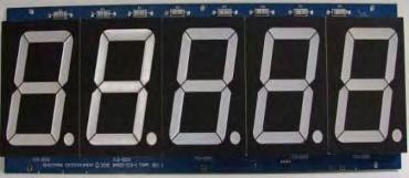


18 Parts High Current PCB Stepper controller board Main CPU Power Distribution PCB 2 Digit Credit Display Jackpot 5 Digit Display Bottom bracket Top bracket Coin Chute and Mechs Control Panel Ball Assembly Optical Receivers Solenoid Assembly Wheel Support Pipes 18
Table of Contents. General Operation. 3 How Slam-A-Winner plays How the Wheel Scores How the Ball Lift works Programming Options...
 61-MAN-B Table of Contents General Operation. 3 How Slam-A-Winner plays How the Wheel Scores How the Ball Lift works Programming Options... 4-6 Troubleshooting Guide. 7-8 Parts Identification 9 Schematics
To Purchase This Item, Visit BMI Gaming
 Table of Contents General Operation. 3 How Slam-A-Winner plays How the Wheel Scores How the Ball Lift works Programming Options... 4-6 Troubleshooting Guide. 7-8 Parts Identification 9 Schematics 10-13
Smokin Token. Operating Instructions. C.P.U. Version ST8 Sound Version H8
 Smokin Token Operating Instructions C.P.U. Version ST8 Sound Version H8 Manual Revision 9/7/2000 Smokin Token Operating Instructions TABLE OF CONTENTS Introduction 3 Game Play 3 Changing Ticket Wheel Values
ICEBALL FX Service Manual
 ICEBALL FX Service Manual Innovative Concepts in Entertainment 10123 Main Street Clarence, NY 14031 (716) 759-0360 Monday through Friday 8:30 am to 6pm Eastern Standard Time www.icegame.com 1 Table Of
BIG WHEEL 1 or 2 player SERVICE MANUAL
 Issued to Production 20th August 1997 BIG WHEEL 1 or 2 player SERVICE MANUAL Produced by Harry Levy Amusement Contractor Ltd Pysons Road Industrial Estate Broadstairs, Kent, England CT10 2LF Tel *843 866464
To Purchase This Item, Visit BMI Gaming (800) Single player Sideshow installation and maintenance
 Single player Sideshow installation and maintenance") Single player Sideshow installation and maintenance 1 1. Installation 1.1 Unpacking 1.2 Assembling 1.3 Set up 2. Game operation 2.1 Gun consoles 2.2 Main cabinet 2.3 Target descriptions 2.3.1 Stars and
Single player Sideshow installation and maintenance 1 1. Installation 1.1 Unpacking 1.2 Assembling 1.3 Set up 2. Game operation 2.1 Gun consoles 2.2 Main cabinet 2.3 Target descriptions 2.3.1 Stars and
USA Ticket Dave & Buster
 USA Ticket Dave & Buster Produced by: Harry Levy Amusement Contractor Ltd Patricia Way Pysons Road Industrial Estate Broadstairs Kent CT10 2LF Tel 0044 1843 866 464 Fax 0044 1843 860 144 email: info@harry-levy-amusements.com
FLIP 2 WIN SERVICE MANUAL
 FLIP 2 WIN SERVICE MANUAL NOTICE The Operator of this equipment is responsible for maintaining customer safety at all time. Details set forth in this document must be followed at all times. 9-24-2009 FOREWORD
OWNER S MANUAL. Version WW BAY-TEK INC East Glenbrook Drive Pulaski, WI Web site:
 OWNER S MANUAL Version WW-2.01 BAY-TEK INC. 1077 East Glenbrook Drive Pulaski, WI 54162 E-mail: service@bay-tek.com Web site: www.bay-tek.com Service:... (920) 822-3951 ext. 1102 Parts:... (920) 822-3951
OWNERS AND SERVICE MANUAL INNOVATIVE CONCEPTS IN ENTERTAINMENT INC MAIN STREET, CLARENCE, NY SERVICE: FAX:
 OWNERS AND SERVICE MANUAL INNOVATIVE CONCEPTS IN ENTERTAINMENT INC. 10123 MAIN STREET, CLARENCE, NY 14031 SERVICE: 1-716-759-0360 FAX: 1-716-759-0884 E-MAIL: service@icegame.com WEBSITE: www.icegame.com
PAC-MAN AIR HOCKEY. Air Hockey Table Owner s Manual. Assembly, operation and care instructions.
 PAC-MAN AIR HOCKEY Air Hockey Table Owner s Manual. Assembly, operation and care instructions. Contents Foreword... 2 Product Specifications... 3 Before Assembling... 4 Tools required for Assembling*...
CD100 Series. Operators Manual SINGLE COLUMN CARD DISPENSER
 CD100 Series SINGLE COLUMN CARD DISPENSER Operators Manual Contents 1 Specifications...1 2 Installation...2 2.1 Unpacking and inspection...2 2.2 Installation...2 2.3 Electrical Connections...2 2.4 Initial
Pirate Loot Operation Manual
 Preliminary Pirate Loot Operation Manual WARNING Be sure to read this Operation Manual before using your machine to ensure safe operation. 2012 Bob s Space Racers Incorporated 427 15 th Street, Daytona
FACTORY CONTACT INFORMATION
 FACTORY CONTACT INFORMATION Our Vision: We aspire to be the best in the world at developing and manufacturing coin operated games for our customers. BAY TEK GAMES INC. Pulaski Industrial Park 1077 East
To Purchase This Item, Visit BMI Gaming (800)
") 1 FACTORY CONTACT INFORMATION Our Vision: We aspire to be the best in the world at developing and manufacturing coin operated games for our customers. BAY TEK GAMES INC. Pulaski Industrial Park 1077 East
1 FACTORY CONTACT INFORMATION Our Vision: We aspire to be the best in the world at developing and manufacturing coin operated games for our customers. BAY TEK GAMES INC. Pulaski Industrial Park 1077 East
1993 Ltd - all rights reserved
 1993 Ltd - all rights reserved No part of this publication may be reproduced by any mechanical, photographic or electronic process, or in the form of phonographic recording, nor may it be stored in a retrieval
MANUAL VERSION FEBRUARY
 MANUAL VERSION FEBRUARY 2008 MAINTENANCE AND TROUBLESHOOTING Quick Troubleshooting: WARNING For your safety and to reduce risk of damage to your game read the Important Safety Information in Chapter 1-2
To Purchase This Item, Visit BMI Gaming (800) Overview
 Overview") FIVE STAR REDEEMPTION OCTOSCORE MEGA SINGLE PLAYER TECHNICAL MANUAL June 0, 203 Features Bright Attention Grabbing Graphics & Cabinet Hot looking Lights Exciting Super Fast Skill Stop Oversized Highly
FIVE STAR REDEEMPTION OCTOSCORE MEGA SINGLE PLAYER TECHNICAL MANUAL June 0, 203 Features Bright Attention Grabbing Graphics & Cabinet Hot looking Lights Exciting Super Fast Skill Stop Oversized Highly
LIL HOOPS INSTRUCTION MANUAL
 LIL HOOPS INSTRUCTION MANUAL VER. 1-03 BAY-TEK INC. 1077 EAST GLENBROOK DRIVE PULASKI, WI 54162 E-MAIL: service@bay-tek.com PHONE: (920) 822-3951 FAX: (920) 822-8936 TABLE OF CONTENTS TABLE OF CONTENTS
OPERATING INSTRUCTIONS AND SERVICE MANUAL RACETRACK SCOREBOARD MODEL MP-3805
 OPERATING INSTRUCTIONS AND SERVICE MANUAL RACETRACK SCOREBOARD MODEL MP-3805 TABLE OF CONTENTS 1. GENERAL INFORMATION 1.1 DESCRIPTION 1.2 IDENTIFICATION 1.3 DAMAGE 1.4 DAMAGE CLAIM PROCEDURE 2. INSTALLATION
DOWN THE CLOWN - Flat Top Service Manual Innovative Concepts in Entertainment Main Street Clarence, NY 14120
 DOWN THE CLOWN - Flat Top Service Manual Innovative Concepts in Entertainment 10123 Main Street Clarence, NY 14120 1 2 Table of Contents Safety, Warnings, and Power Requirements 4 Hardware 5 Setup 6-16
GENUINE PARTS INSTALLATION INSTRUCTIONS
 GENUINE PARTS INSTALLATION INSTRUCTIONS DESCRIPTION: APPLICATION: PART NUMBER: DUAL DVD HEADRESTRAINT MONITOR Pathfinder - (204 Above S grade, without factory FES, and VINs ending in less than 650298)
GENUINE PARTS INSTALLATION INSTRUCTIONS
 GENUINE PARTS INSTALLATION INSTRUCTIONS DESCRIPTION: APPLICATION: PART NUMBER: DUAL DVD HEADRESTRAINT MONITOR Pathfinder - (204 Above S grade, without factory FES, and VINs ending in less than 650298)
To Purchase This Item, Visit BMI Gaming (800) Overview
 Overview") To Purchase This Item, Visit BMI Gaming www.bmigaming.com (00) - +...00 FIVE STAR REDEEMPTION Haunted Hotel THREE PLAYER TECHNICAL MANUAL January,00 Features Bright Attention Grabbing Graphics & Cabinet
To Purchase This Item, Visit BMI Gaming www.bmigaming.com (00) - +...00 FIVE STAR REDEEMPTION Haunted Hotel THREE PLAYER TECHNICAL MANUAL January,00 Features Bright Attention Grabbing Graphics & Cabinet
WHISTLE STOP OWNER S MANUAL. Version WS-1.15
 WHISTLE STOP OWNER S MANUAL Version WS-1.15 BAY-TEK INC. 1077 East Glenbrook Drive Pulaski, WI 54162 E-mail: service@bay-tek.com Web site: www.bay-tek.com Service:...(920) 822-3951 ext. 1102 Parts:...
OWNER S MANUAL Version SH August 8, 2008
 OWNER S MANUAL Version SH1-0101 August 8, 2008 BAY TEK GAMES, INC. 1077 East Glenbrook Drive Pulaski, WI 54162 E-mail: service@baytekgames.com Web site: www.baytekgames.com Service:... (920) 822-3951 ext.
CONTROL BOX. Wiring the control box into the vehicle. +12V
 CONTROL BOX Once the display panel is in place, mount the control box within the connecting cable's distance (approximately 3 feet) and secure to the underside of the dashboard. This case does not have
Sideshow installation and maintenance
 Sideshow installation and maintenance From machine serial number SW077 1 1. Installation 1.1 Unpacking 1.2 Assembling 1.3 Set up 2. Game operation 2.1 Gun consoles 2.2 Main cabinet 2.3 Target descriptions
GENESIS KIT for Rowe. INSTALLATION: BC12R, 1400 Special tools needed drill and a 5/32 bit
 Page 1 of 5 GENESIS KIT for Rowe INSTALLATION: BC12R, 1400 Special tools needed drill and a 5/32 bit THE COIN DETECTOR LIGHT(S) ON THE COIN DISPENSER FRAME NEED TO BE THE NEWER RED LED TYPE. IF YOU HAVE
WARNING. Be sure to read this Operation Manual before using your machine to ensure safe operation.
 WARNING Be sure to read this Operation Manual before using your machine to ensure safe operation. DECEMBER 2008 COMET CATCHER ARCADE 2 TABLE OF CONTENTS 1. SPECIFICATIONS 2. INTRODUCTION 2-1. Overview
Lingenfelter NCC-002 Nitrous Control Center Quick Setup Guide
 Introduction: Lingenfelter NCC-002 Nitrous Control Center Quick Setup Guide The NCC-002 is capable of controlling two stages of progressive nitrous and fuel. If the NCC-002 is configured only for nitrous,
ECT Display Driver Installation for AP2 Module
 ECT Display Driver Installation for AP2 Module Overview The ECT Display Driver is a small module with a removable wire harness that mounts behind the driver's foot well cover. All wiring connections are
Continental Hydraulics Installation Manual CEM-AA-A
 Continental Hydraulics Installation Manual CEM-AA-A Description: This power amplifier drives either single or dual solenoid proportional valve coils up to 2.6A. It is suitable to control current to proportional
OPERATING INSTRUCTIONS AND SERVICE MANUAL FOOTBALL SCOREBOARD MODEL MP-3455 WITH MP-3000 CONTROL
 OPERATING INSTRUCTIONS AND SERVICE MANUAL FOOTBALL SCOREBOARD MODEL MP-3455 WITH MP-3000 CONTROL EFFECTIVE S.N.XXXX, JAN 1, 1994 TABLE OF CONTENTS 1. General Information 1.1 Description 1.2 Identification
Contents. Section 2: Electrical - Switches, Solenoids and Motors
 Contents Section 2: Electrical - Switches, Solenoids and Motors... 2-3 Switches...2-3 Switches A, B, C and D...2-4 Error Code A Switch...2-4 Error Code B Switch...2-5 Error Code C Switch...2-5 Error Code
Operation Manual SPIDER WEB WARNING. Be sure read this Operation Manual before using your machine to ensure safe operation.
 Operation Manual SPIDER WEB WARNING Be sure read this Operation Manual before using your machine to ensure safe operation. SERVICE: Bromley Inc 420 Crossen Elk Grove Village, Illinois 60007 Tel: 847-427-0639-1
To Purchase This Item, Visit BMI Gaming (800)
") OWNERS AND SERVICE MANUAL INNOVATIVE CONCEPTS IN ENTERTAINMENT INC. 10123 MAIN STREET, CLARENCE, NY 14031 SERVICE: 1-716-759-0360 FAX: 1-716-759-0884 E-MAIL: service@icegame.com WEBSITE: www.icegame.com
OWNERS AND SERVICE MANUAL INNOVATIVE CONCEPTS IN ENTERTAINMENT INC. 10123 MAIN STREET, CLARENCE, NY 14031 SERVICE: 1-716-759-0360 FAX: 1-716-759-0884 E-MAIL: service@icegame.com WEBSITE: www.icegame.com
AURORA SERIES GAUGES FUEL GAUGE SUGGESTED TOOLS AND MATERIALS. 3 3 /8 in (85.7 mm) PARTS LIST
 PARTS LIST") GAUGE INSTALLATION. Select mounting locations for the fuel gauge. 2. Cut a 2 /6 (52 mm) diameter hole for the gauge and test for proper fitmate. 3. Tighten the gauge with the enclosed Aurora Mounting Clamp
GAUGE INSTALLATION. Select mounting locations for the fuel gauge. 2. Cut a 2 /6 (52 mm) diameter hole for the gauge and test for proper fitmate. 3. Tighten the gauge with the enclosed Aurora Mounting Clamp
SECTION 5 DIAGNOSTIC TROUBLE CODES (DTC)
") 5 1. DTC MEMORY SECTION 5 Diagnostic Trouble Codes (DTCs) are logged in a list in TCM memory. The DTCs contained in the list have information recorded as shown in Table 5 1 (DTC example). The TCM is capable
5 1. DTC MEMORY SECTION 5 Diagnostic Trouble Codes (DTCs) are logged in a list in TCM memory. The DTCs contained in the list have information recorded as shown in Table 5 1 (DTC example). The TCM is capable
9200 Revenue Meter. Model Certification Current Inputs. Complies with the accuracy requirements of the ANSI C Revenue Metering Standard
 9200 Revenue Meter This document applies to 9200 meters with firmware version 205 or greater, and explains how to set up and seal the meter for revenue functionality. Revenue meters provide power measurements
Installation Instructions & Users Manual
 Installation Instructions & Users Manual UTILITY/ BUILDING INPUT 120 VAC ( OPTION) 15-20A N L CONTROL BOARD G SECURITY LIGHTING POWER SUPPLY (OPTION) CHARGER- POWER SUPPLY ASSBY XFMR (OPTION) CBM MODEL
Ch 4 Motor Control Devices
 Ch 4 Motor Control Devices Part 1 Manually Operated Switches 1. List three examples of primary motor control devices. (P 66) Answer: Motor contactor, starter, and controller or anything that control the
Contents. Section 3A: Consolidated Electronics... 3A-3. General Information... 3A-3
 Contents Section 3A: Consolidated Electronics... 3A-3 General Information... 3A-3 Consolidated High Voltage Box... 3A-5 Left Side... 3A-5 Right Side... 3A-6 Bottom... 3A-7 Internal... 3A-8 Lane Power Contactors...
IFD AIR CLEANER SERVICE MANUAL
 IFD AIR ER SERVICE MANUAL PUB NO. 34-3446-01 1 4 COMPONENTS OF THE AIR ER 5 3 6 3 2 7 8 1 2 3 AIR FLOW 1 1) Pre-filter - traps large particles such as hair and lint before they can enter the cell section.
Royal Care Series. Installation & Operations Manual
 Royal Care Series Installation & Operations Manual WS-102 WS-105 WS-109 WS-115 Note: You must read all installation & operation instructions prior to assembly and use of this unit. 1 P a g e Table of Contents
CABINET REEL OPERATING INSTRUCTIONS
 CABINET REEL OPERATING INSTRUCTIONS MODELS 15, 25, 40 & 60 SERIES RAPID-AIR CORPORATION 4601 KISHWAUKEE ST. ROCKFORD, IL 61109-2925 Phone: (815) 397-2578 Fax: (815) 398-3887 Web Site: www.rapidair.com
Inteli-Lift GEN II DUMBWAITER
 1 877-345-4387 530-295-4900 www.eilifts.com Inteli-Lift GEN II DUMBWAITER The Easiest Dumbwaiter system on the Market Fully UL Certified Dumbwaiter Systems UL File # SA32120 This manual will cover the
MODEL 422 Submersible Pump Controller
 MODEL 422 Submersible Pump Controller Monitors True Motor Power (volts x current x power factor) Detects Motor Overload or Underload Operates on 120 or 240VAC, Single-phase or 3-phase Built-in Trip and
Service & Maintenance
 Service & Maintenance Amplifier Monitor LEDs & Tubes (Wall-Rock-PV) Translucent Panel (Wall-Rock-PV) Glass Panel (Rock-Star) Fans & Filter G2-1 External Peavey Amplifier) Amplifier Removal 1. Disconnect
Contents. Section 2: Electrical - Switches, Solenoids and Motors
 Contents Section 2: Electrical - Switches, Solenoids and Motors... 2-3 Switches... 2-3 Switches A, B, C and D... 2-4 Error Codes A Switch... 2-4 Error Codes B Switch... 2-4 Error Codes C Switch... 2-5
Thru-Beam Photo Eye Monitored / Non-Monitored Battery Powered Emitter
 Model # IG-2 GUARD-2 TM Thru-Beam Photo Eye Monitored / Non-Monitored Battery Powered Emitter Installation Instructions The Invisi-Guard-2 thru beam photo optic system sends an invisible beam of light
REC-11+ REMOTE RECEIVER UNIT
 Resetting The Programmable Features The installer may quickly and easily return all 17 programmable features back to the factory settings. Changing individual features were explained in detail in the previous
SmartPak Welding Controller WK-MPS-16 Constant Current
 SmartPak Welding Controller WK-MPS-16 Constant Current Features Latest state of the art ATMEL 8 bit microprocessor technology Synchronous digital welding control allows absolute precision Up to16 programmers
Validator and Control Board Update Instructions for BC1
 Validator and Control Board Update Instructions for BC1 Installation Overview The update kit for the Rowe BC1 enables the changer to interface with a Mars AE/VN 120-volt validator. The validator determines
INSTALLATION INSTRUCTIONS AND OPERATION MANUAL
 INSTALLATION INSTRUCTIONS AND OPERATION MANUAL UL325-2010 Compliant Commercial and Industrial Door Operator Logic Control Continuous Duty IMPORTANT INSTALLATION INSTRUCTIONS WARNING To reduce the risk
with lcd display 12-42v
 instructions for: AUTO PROBE with lcd display 12-42v MODEL No: PP7 Thank you for purchasing a Sealey product. Manufactured to a high standard this product will, if used according to these instructions
DMR 3005 WM ONE ZONE WIRELESS DIMMER RECEIVER
 E363518 DMR 3005 WM ONE ZONE WIRELESS DIMMER RECEIVER 20725 NE. 16 AVE. #A-33 MIAMI, FLORIDA 33179 Tel: (305) 652-2599 Fax: (305) 650-8812 www.lumiron.com Email: sales@lumiron.com 1 Benefits and Features
INSTALLATION INSTRUCTIONS AND OPERATION MANUAL
 INSTALLATION INSTRUCTIONS AND OPERATION MANUAL NEMA 4X UL325-2010 Compliant Commercial and Industrial Door Operator Logic Control Continuous Duty IMPORTANT INSTALLATION INSTRUCTIONS WARNING To reduce the
ARCADE OPERATIONS MANUAL Version
 ARCADE OPERATIONS MANUAL Version 062711 WARNING Be sure to read this Operation Manual before using your machine to ensure safe operation. Table of Contents 2011 Bob s Space Racers Incorporated 427 15 th
Dodge Cummins Positive Air Shutoff
 1998-2002 24V 5.9 Dodge Cummins Positive Air Shutoff (I-00181) 1 INSTALL MANUAL 1998.5-2002 5.9 Dodge Cummins Positive Air Shutoff P/N# 1036719 P/N# 1036719-M UPLEASE READ ALL INSTRUCTIONS BEFORE INSTALLATION
PAC-MAN SMASH. Operation Manual
 PAC-MAN SMASH Operation Manual The actual product may differ slightly from the illustrations in this Operation Manual. To ensure safe operation of the machine, be sure to read this Operation Manual before
Installation and Maintenance Instructions. World Leader in Modular Torque Limiters. PTM-4 Load Monitor
 World Leader in Modular Torque Limiters Installation and Maintenance Instructions PTM-4 Load Monitor 1304 Twin Oaks Street Wichita Falls, Texas 76302 (940) 723-7800 Fax: (940) 723-7888 E-mail: sales@brunelcorp.com
P3 Electronic Brake Control
 P3 Electronic Brake Control For 2, 4, 6 and 8 brake applications READ THIS FIRST: Read and follow all instructions carefully before installing or operating the P3. Keep these instructions with the Brake
The RPM module will remain in Normal mode by default. It will also return to this mode after settings have been recalled or changed
 Shiftlight Operating Instructions: Setting up your shiftlight: The RPM module requires you to set the turn-on RPM and the number of cylinders. Once these two pieces of information are set, they will not
Controller Specification Sheet
 Controller Specification Sheet MC9320AXXXBX Proportional Inhibitor Dosing, Conductivity Bleed Control, Redox Control of Oxidising Biocide and Secondary Biocide Dosing PULSAtrol Controllers are microprocessor
Whac-A-Mole pro Operation Manual
 Whac-A-Mole pro Operation Manual WARNING Be sure to read this Operation Manual before using your machine to ensure safe operation. 2011 Bob s Space Racers Incorporated 427 15 th Street, Daytona Beach,
TIP SHEET T0937. Installation Tips For RS00/PS00 + ADS-TBSL-PL + SPDT
 Installation Tips For RS00/PS00 + ADS-TBSL-PL + SPDT TIP SHEET T0937 Thank you for purchasing your remote start from MyPushcart.com - an industry leader in providing remote starts to do-it-yourself installers
RFID SECURITY SYSTEM #WI-RFID. Before you start ANY electrical work; always disconnect the POWER at the BATTERY before doing ANYTHING.
 RFID SECURITY SYSTEM #WI-RFID Thank you for buying a StreetWorks product. Be confident that it will provide the quality and performance that you demand for your car. Please read and understand all installation
Model: AEM14 Analog Engine Monitor
 Model: AEM14 Analog Engine Monitor Installation and Setup Manual Version 1 Table of Contents Monitor Overview DMK Engine Monitor Kit Section 1: Initial Setup 1.1 Internal Settings Switches Figure 1. AEM14
ECONOMISER SERIES E2T USER MANUAL
 TURBO S.R.L. Electronic Control Systems for Dust Collectors e-mail: info@turbocontrols.it web: www.turbocontrols.it TEL. ++39 (0)362 574024 FAX ++39 (0)362 574092 ECONOMISER SERIES E2T USER MANUAL 24/06/2014
Table of Contents. Timer Identification Timer ID BLU-U Features: 1K 6K BLU-U Features 1K 6K
 DUSA Pharmaceuticals, Inc. Table of Contents Go to Chart # Timer Identification Timer ID BLU-U Features: 1K 6K BLU-U Features 1K 6K BLU-U Features: 10K BLU-U Features 10K BLU-U Symptom Fans Running, Timer
Intelli-Feed Controller User s Manual Intelli-Feed Digital Tachometer and Hourmeter
 Intelli-Feed Controller User s Manual Intelli-Feed Digital Tachometer and Hourmeter Part #: 9047 Table of Contents: Table of Contents 2 Intelli-Feed TM User Interface 3 Equipment Diagnostic Indicators
Parker AC10 Frequency Inverter (to 22kW) Easy Start Guide
 Easy Start Guide") Parker AC10 Frequency Inverter (to 22kW) Easy Start Guide CAUTION: 1)Do not re-set while the motor is rotating 2)Perform parts replacement after discharge is finished 3)Do not connect output terminals
Parker AC10 Frequency Inverter (to 22kW) Easy Start Guide CAUTION: 1)Do not re-set while the motor is rotating 2)Perform parts replacement after discharge is finished 3)Do not connect output terminals
To Purchase This Item, Visit BMI Gaming (800)
") OWNERS AND SERVICE MANUAL INNOVATIVE CONCEPTS IN ENTERTAINMENT INC. 10123 MAIN STREET, CLARENCE, NY 14031 SERVICE: 1-716-759-0360 FAX: 1-716-759-0884 E-MAIL: service@icegame.com WEBSITE: www.icegame.com
OWNERS AND SERVICE MANUAL INNOVATIVE CONCEPTS IN ENTERTAINMENT INC. 10123 MAIN STREET, CLARENCE, NY 14031 SERVICE: 1-716-759-0360 FAX: 1-716-759-0884 E-MAIL: service@icegame.com WEBSITE: www.icegame.com
Continuing Education Course #206 Introduction to Designing Machine Control Systems Part 2
 1 of 5 Continuing Education Course #206 Introduction to Designing Machine Control Systems Part 2 1. Continuing to answer the following questions indicates that you understands that the presented material
1.0 Features and Description
 1.0 Features and Description The is an intelligent actuator designed for precise control of quarter turn valves and dampers. Using stepper motor technology, the SmartStep proportionally positions valves
PowerView PV380-R2 Mechanical Configuration
 PowerView PV380-R2 Mechanical Configuration Operations Manual *Products covered in this document comply with European Council electromagnetic compatibility directive 2004/108/EC and electrical safety directive
Installation and User Manual. with RAIN SENSOR.
 with RAIN SENSOR www.solarsmartopener.com Revision..0 TABLE OF CONTENTS Features In The Box Further Items Required Basic Operation Solar Panel and Operator Installation Operator Installation Solar Panel
Dodge Cummins Positive Air Shutoff
 21 October 2011 1998-2002 24V 5.9 Dodge Cummins Positive Air Shutoff 1 1998.5-2002 5.9 Dodge Cummins Positive Air Shutoff P/N# 1036719 P/N# 1036719-M UPLEASE READ ALL INSTRUCTIONS BEFORE INSTALLATION 21
VEND PROGRAMMING. In order to fully understand the material in this section, become familiar with the following terms:
 VEND PROGRAMMING Section 3 Definitions In order to fully understand the material in this section, become familiar with the following terms: 1. Adjustable Wand. The XP wand that rotates on the trolley 90,
Laboratory 10 Assignment. Introduction
 ME576 Laboratory 10 Assignment Introduction For this lab, the conveyor trainer will be operated using the Siemens S5 PLC. The conveyor system is supposed to sort the metal pegs from rings on the moving
PIRATE S BOUNTY SHOOTING GALLERY INSTALLATION AND MAINTENANCE MANUAL
 PIRATE S BOUNTY SHOOTING GALLERY INSTALLATION AND MAINTENANCE MANUAL AMUSEMENT ELECTRONICS 3215 W. HAMPDEN AVE SHERIDAN CO 80110 PH: 714-538-7118 EMAIL: ZACH@ZANIGAMES. COM INTRODUCTION Thank you for purchasing
PRODUCT MANUAL Gecko Wireless One Zone LED Dimmer and Receiver
 Product Description The Gecko Wireless One Zone Wall LED Dimmer has been designed to bring light control easily. No wires or switch box locations are needed, just stick or mount the Gecko to any flat location
OV4 Installation Manual
 Orange Amplifiers OMEC House 08 Ripon Way Borehamwood Hertfordshire WD6 JA ENGLAND Tel: +44 0 8905 88 Fax: +44 0 8905 868 Email:info@omec.com OV4 Installation Manual TM Orange USA 065 Peachtree Industrial
AFP MEA Mini Electrical Rotary Actuator User s Instructions
 AFP MEA Mini Electrical Rotary Actuator User s Instructions Please read and understand the instruction related to this product. These are User s Instructions and the AN-05 application notes. WARNING Failure
Dodge Cummins Positive Air Shutoff
 10 June 2013 1998-2002 24V 5.9 Dodge Cummins Positive Air Shutoff 1 1998.5-2002 5.9 Dodge Cummins Positive Air Shutoff P/N# 1036719 P/N# 1036719-M UPLEASE READ ALL INSTRUCTIONS BEFORE INSTALLATION 10 June
OWNERS AND SERVICE MANUAL INNOVATIVE CONCEPTS IN ENTERTAINMENT INC MAIN STREET, CLARENCE, NY SERVICE: FAX:
 OWNERS AND SERVICE MANUAL INNOVATIVE CONCEPTS IN ENTERTAINMENT INC. 10123 MAIN STREET, CLARENCE, NY 14031 SERVICE: 1-716-759-0360 FAX: 1-716-759-0884 E-MAIL: service@icegame.com WEBSITE: www.icegame.com
CHAPTER S e t u p NOTICE:
 CHAPTER Setup NOTICE: Information in this manual may change without notice. Midway Games West Inc. reserves the right to make improvements in equipment function, design, or components as progress in engineering
Step 1 Wiring your remote start. Installation Tips for your Remote Start system (for GM vehicles) V3.3 revised 9/12/2013
 V3.3 revised 9/12/2013") Installation Tips for your Remote Start system (for GM vehicles) V3.3 revised 9/12/2013 Thank you for purchasing your remote start from MyPushcart.com - an industry leader in providing remote starts to
Installation Tips for your Remote Start system (for GM vehicles) V3.3 revised 9/12/2013 Thank you for purchasing your remote start from MyPushcart.com - an industry leader in providing remote starts to
ARCADE OPERATION MANUAL
 ARCADE OPERATION MANUAL 11-08-11 WARNING Be sure to read this Operation Manual before using your machine to ensure safe operation. 2011 Bob s Space Racers Incorporated 427 15 th Street, Daytona Beach,
Driver s Display. ALFA-Elite & ALFA-Pro. Owners Manual. Rev 1.2, July (Preliminary) (September 21, 2012) Small Systems Specialists
 (September 21, 2012) Small Systems Specialists") Driver s Display ALFA-Elite & ALFA-Pro Owners Manual Rev 1.2, July 2010 (Preliminary) (September 21, 2012) Small Systems Specialists P.O. Box 310 Windsor, NJ 08561 Phone 609-301-0541 Email ALFA@Rally.cc
Driver s Display ALFA-Elite & ALFA-Pro Owners Manual Rev 1.2, July 2010 (Preliminary) (September 21, 2012) Small Systems Specialists P.O. Box 310 Windsor, NJ 08561 Phone 609-301-0541 Email ALFA@Rally.cc
ECLIPSE Laundry Dispenser Controller
 ECLIPSE Laundry Dispenser Controller Reference Manual Programming and Operation Online and downloadable Product Manuals and Quick Start Guides are available at www.hydrosystemsco.com Please check online
Norcal Power/SWR Meter Assembly & Operating Manual. Revision 1D 10/15/2008
 Norcal Power/SWR Meter Assembly & Operating Manual Revision 1D 10/15/2008 Copyright 2008 NorCal QRP Club Page 1 of 21 Contents CONTENTS...2 INTRODUCTION...3 SPECIFICATIONS...3 ASSEMBLY...4 OPERATING GUIDE...15
TURBODYNO **WARNING**
 TURBODYNO **WARNING** It is dangerous to work in the vicinity of a lead-acid battery since they generate explosive gases during normal battery operation, To prevent an explosion when using a lead-acid
e-track Certified Driver Operating Manual
 e-track Certified Driver Operating Manual Copyright 2016 all rights reserved. Page: Table of Contents System Overview 4 Login 5 Certifying Logs 6 Unidentified Driver Records 8 Requested Edits 9 ECM Link
Ball Speed Display Manual
 Ball Speed Display Manual JOYSTICK SCORING LIMITED 2001-7 Congratulations on purchasing the exciting new Ball Speed Display from Joystick Scoring. This product gives your existing scoring system sophisticated
R & D SPECIALTIES ROTROL I USER'S MANUAL
 R & D SPECIALTIES ROTROL I USER'S MANUAL TABLE OF CONTENTS INTRODUCTION...2 SPECIFICATIONS...2 CONTROLS AND INDICATORS...3 TIME DELAYS...4 INSTALLATION...5 SYSTEM OPERATION...9 TROUBLESHOOTING...13 OPTIONAL
Dodge Cummins Positive Air Shutoff
 21 October 2011 2003-2007 5.9 Dodge Cummins Positive Air Shutoff 1 2003-2007 5.9 Dodge Cummins Positive Air Shutoff P/N# 1036720 P/N# 1036720-M UPLEASE READ ALL INSTRUCTIONS BEFORE INSTALLATION 21 October
Ford 7.3L Powerstroke Positive Air Shutoff
 24 October 2012 Ford 7.3L 1999.5-2003 Positive Air Shutoff 1 1999.5-2003 Ford 7.3L Powerstroke Positive Air Shutoff P/N# 1036700 P/N# 1036700-M UPLEASE READ ALL INSTRUCTIONS BEFORE INSTALLATION 24 October
GENESIS Electronic Brake Controller Hayes Brake Controller Company - P/N 81790
 GENESIS Electronic Brake Controller Hayes Brake Controller Company - P/N 81790 INSTALLATION MANUAL For trailers with 2-8 electric brakes and vehicles with 12 volt negative ground systems only. READ AND