INSTALLATION MANUAL APPLICATION: T 125G 45psi) CLASS 1-CLASS 8 *Requires a Fuel Line Kit*
|
|
|
- Thomasina Foster
- 5 years ago
- Views:
Transcription


1 INSTALLATION MANUAL APPLICATION: T 125G 45psi) CLASS 1-CLASS 8 *Requires a Fuel Line Kit*

2 WARNINGs! WARNING: Do not tie FASS Return in with engine return. Back pressure can cause damage to engine. Read all instructions before starting installation of this product! Installing the improper FASS Pump can cause severe engine damage. This unit was not designed to be used on Unit Injected Mechanical Engines. Refer to the FASS kits with UIME in the model number. FASS T 125G Recommended Application Class 1 Class 8, Agriculture, Industrial, Recreational, Hwy and off-road. Applications requiring fuel flow demands of 45psi and less than 125gph Do Not Remove any factory installed secondary fuel filter! Removal of a factory installed secondary fuel filter may void the engine manufacturer s warranty. This is the fuel filter between the engines fuel pump and the injectors. Be sure that the serial # on this installation manual matches that of the outside of the box. Keep debris from entering the internals of the system during installation. Getting debris in the water separator nipple can lock up the motor. If the motor does lock up from debris call FASS for technical assistance. Properly secure lines to prevent chaffing. Use caution when drilling. Steer clear of any electrical wires, air lines or other damageable components. Below is a chart of available fuel line kits FASS has to offer. Using one of these kits will make the installation cost effective and easier. This manual will refer to these FLK # s Take caution when producing extra ports. Do only as directed as to be careful not to cause back pressure to engine return or severe engine damage.
3 INSTALLATION MANUAL Follow these steps to ensure a simple installation of your new FASS TITANIUM FUEL SYSTEM 1. Read the installation manual completely before attempting installation. The installation of this product indicates that the buyer has read and understands the limitations of the FASS manufacturers warranty agreement and accepts the responsibility of its terms and conditions. 2. Inventory the package components. Notify the place of purchase immediately of any parts missing or damaged. 3. The installation recommendations contained herein are guidelines. Use good judgment and take into consideration your vehicles' accessories. 4. For best results in accuracy and efficiency (due to training, communication, and our relationship with our dealer network), we recommend a ViP FASS dealer for the installation. They are prepared to install the FASS fuel pumps with the most efficiency. If a situation/problem arises during the installation, they are the most prepared for that situation/problem. DPPI is not responsible for any installation mistakes.


4 Titanium Duty Series 125 GPH 45 PSI (Approximately) A fuel pressure gauge is highly recommended to identify fuel filter life and to prevent engine damage! H Coolant Heater E To Engine R Fuel Return to Tank T Fuel Inlet 2nd Electric Heater Port G Fuel Pressure Electric Heater Port Serial Number Location Installation Step 1: Install Electrical Harness Step 2: Prepare Suction and Return Lines Step 3: Mount Fuel System Step 4: Install Fuel Line Step 5: Check Installation


5 Contents MP-9050 BR-2001 WH-1005 *WE-1001*


6 Mounting Package Contents RS-2684 RS-1001 Ring Terminal Spade Terminal 4 3/8-16 x 1 1/2 Hex Bolt 4 Locking Nut 3/8 Mounting template 3 Hex Bolt 1/ /4" 3 WA-1001D


7 Step 1: Installing Electrical Harness The installation of the electrical harness is done first, allowing power to be applied to the pump for lubrication purposes. A. Select best location in firewall for passage of wiring harness from cab to engine compartment. B. Find or drill a 7/8 hole in firewall. Install RS-2684 grommet for ease of installation and protection of wire harness. C. Connect WE-1001 wire extension to the WH D. Route red wire/ loom of the wire extension through the grommet in the firewall to the ignition or fuse panel. The use of corrosion preventative spray and dielectric grease is recommended where electrical connection are made.. E. Connect the Red lead to the ON terminal of the ignition switch or a terminal on the circuit breaker board that is hot when the key is on. Use a test probe to locate the hot side of the circuit in the fuse block. F. Using the ring terminals, connect the green wire of the wire harness to the negative post and the red wire to the positive post of the battery. G. Secure relay in an upright position, preferably on the firewall out of the weather. H. Properly secure all electrical leads and harness. Note: When connecting ground make sure connection is on a clean and not painted surface, ie Engine, Frame, or Battery.


8 NOTE ATTENTION: While installing fittings into Titanium pump DO NOT Apply side pressure to draw tube of pump Proper Improper


.")


9 Step 2: Mounting the FASS Some of the photo s are of a different application, procedures are the same. A. Remove primary fuel and/or water separator. If primary filter is part of the fuel pump, ignore this step. NOTE: Before installing fittings make sure to inspect for burs or flare imperfections. When cutting fuel line make sure to blow out line to keep debris from moving forward. B. Using thread tape, install the fittings into the E and the T ports (on opposite end). Torque to 40 lb./ ft.² Note: Do Not Put Thread Tape on Flare of Fitting ***The use of thread sealant is not recommended*** C. Attach BR-2001 to back of system using the spacers and 1/4 bolts. Use the two bottom bolts and the very top one bolt opening.

 mounting points (using the template located on the")


 - 3/8 bolts & flange nuts placing the")

10 Step 2: Mounting the FASS Some of the photo s are of a different application, procedures are the same. D. Position system where it will be mounted. Mark the (4) mounting points (using the template located on the contents page). Prior holes may be used. Drill these marked locations with a 13/32 bit. E. Connect factory plug into the FASS harness. Turn key to on. With pump operating, turn pump over, liberally spray WD-40 (or equivalent) into water separator nipple lubricating the Gerotor. F. Assemble to frame using the (4) - 3/8 bolts & flange nuts placing the RS-1001 between the frame and bracket. An optional accessory is SFB G. Apply motor oil to O-rings located on filters. Attach to system and tighten appropriately Note: O-Ring must be put back on suction side of pump. Failure to do so can result in priming issues, cavitation, or pressure loses.
11 Step 3: Identify Fuel Line Configuration For optimal engine performance gains, the return line should return to its own port. A. Fuel lines, excluding nylon type fuel lines, in excess of 6 years old should be replaced due to interior lining deterioration. This condition can cause many problems including but not limited to: fuel starvation, uneven fuel tank levels and etc. B. When routing the return line from the FASS Fuel System, you will need to first identify your current fuel system. Now match with the correct fuel line section below and follow the corresponding procedures. Uneven fuel level conditions can occur between the tanks if the pickup/return lines are improperly installed. B1. Most Popular - Usually on 1994 Trucks & Newer including Volvo and Mercedes Engines: Double Draw/Double Return Line System. FASS fuel line kit (FLK-S03) or Double Vent Return Line Kit for trucks without the extra port of the fuel tanks(flk-so6)should have all of the product to complete this process B2. 2nd Most Popular - Usually on 1993 Trucks & Older (except 359 Peterbilt - next selection): Single Draw/Single Return Line System. FASS fuel line kit (FLK-S02) should have all of the product to complete this process B Peterbilt: Single Draw Out of Cross Over Fuel Line/Single Return Line System Dual Tank Recommendation: 1st Choice - Convert to a complete Double Draw/Double Return Line System(FLK-S03) or Double Vent Return Line Kit (FLK-S06). 2nd Choice - Convert to a true Single Draw/Single Return Line System FLK-S02). B4. DD15 - DD15 Supply/Double Return Fuel Line Kit (FLK-S07) should have all of the product to complete this process

12 Step 4: Double Draw/Double Return Fuel Line System Caution: Do Not use sealant on AN fittings. Only use sealant on threads installed into pump assembly or joining fittings. Note: No extra ports? - Refer to the option located at the back of the manual. Return line from FASS with straight ends to cross member where the line will T off. From T to each fuel tank with 1-straight fitting & 1-90 fitting on each line. These lines must be the exact length on both sides. A. Locate extra bung on the fuel tanks, most KW s have a 1/4, Peterbilt have 3/8 or 1/2 extra pipe plug located by the fuel lines at the top of the fuel tank. Other models may have an extra port some where at the top of the fuel tank. Remove the plugs and install a 8 AN fitting into each tank. It maybe necessary to use a bushing to adapt fitting to tank. B. Install (90 or straight) fitting into fuel line using the following procedures: refer to this procedure when necessary. B1. Assemble fuel line into female hose fitting (reverse threads), then apply a modest amount of oil to the interior lining. B2. Secure female end in vise. B3. Oil male JIC swivel (90 or straight) and assemble into female end. B4. The male portion should tightened all the way, as seen.


13 Step 4: Double Draw/Double Return Fuel Line System C. Assemble the T using (1) 3/8 NPT T, (2) -8 ANx3/8 MPT & (1) -8 ANx3/8 MPT 90 as seen in the photo. D. Attach the line completed in Step 4b to the return port of the FASS labeled with an R. Route to the center of the nearest cross member aligned with the ports in the fuel tank being used for return fuel. Measure & mark this line as it will connect to the 90 fitting of the T in this location. E. Cut the fuel line and assemble a 8 AN hydraulic fitting in the opposite end of the line connecting to the R port of the FASS. F. Assemble a 8 AN hydraulic fitting into one end of the remaining fuel line. Route this fuel line from straight fitting of the T to the return port in the fuel tank, mark & cut. G. Caution: Route the side with the exhaust first as it will be necessary to travel below the frame to avoid the exhaust, each side has to be the exact same length. Later it will install as seen. H. Cut the remaining fuel line to the Exact same length line as the line in Step 4f. I. Assemble (1) of each 8 AN 90 & -8 AN Straight into each line addressed in Steps 4f & 4g. J. In the same manner as previously covered, route and loosely connect the assembled fuel lines discussed in this section to the appropriate points of connection including the T. K. Torque all connections to 18 ft./lbs. Secure the fuel line and all fittings. Continue to Step 5


14 Step 4: Single Draw/Single Return Fuel Line System Caution: Do Not use sealant on AN fittings. Only use sealant on threads installed into pump assembly or joining fittings. Note: No extra ports? - Refer to the option located at the back of the manual. A. Locate a fuel return port into the fuel tank. Most KW s have a 1/4, Peterbilts have 3/8 or 1/2 extra pipe plug located by the fuel lines at the top of the fuel tank. Other models may have an extra port some where at the top of the fuel tank. Remove the plugs and install the 8 ANx5/16 NPT into each tank, it maybe necessary to use a brass bushing. B. Install 8 AN hydraulic fitting into fuel line using the following procedures: refer to this procedure when necessary. B1. Assemble fuel line into female hose fitting (reverse threads), then apply a modest amount of oil to the interior lining. B2. Secure female end in vise. B3. Oil male end of 90 JIC swivel fitting and assemble into female end. B4. The male portion should tightened all the way, as seen.


15 Step 4: Single Draw/Single Return Fuel Line System C. Attach the line completed in Step 4b to the return port of the FASS labeled with an R. Route to the port in the fuel tank being used for return fuel. Measure, mark & cut. D. In the same manner as previously covered, route and loosely connect the fuel lines discussed in this section to the appropriate points of connection. E. Torque all connections to 18 ft./lbs. Secure all fuel lines and fittings. Continue to Step 5
. B.")
16 Step 5: Fuel Supply Line A. Attach the fuel supply line from the fuel tank to the FASS using a L or one of the fitting from the filter housing removed in step 2. IF fuel supply line connects directly to engine-the primary fuel filter is not remote mounted-skip to step C (Usually, not always, on NTC/STC s and N- 14 s). B. Attach the fuel supply line from the FASS to the engine pump using a L or one of the fittings from the filter housing removed in step 2. Once completed, you are finished with step 5 and you may go directly to step 6. C. Disconnect fuel line from engine. Connect to T port of the FASS. D. Assemble a 10 AN hydraulic fitting into one end of the #10 fuel line and loosely connect to either the FASS or the engine. E. Route fuel line to open port (engine or FASS) measure and cut. Note: Part # S from Fleetguard will take the place of the engine mounted fuel filter. F. Assemble a 10 AN hydraulic fitting into the cut end. Remember, clocking of the fuel fittings may be necessary to connect to ports in discussion. G. Attach the assembled fuel line to the FASS and engine. CAUTION: IT IS VERY IMPORTANT TO BLOW THIS FUEL LINE OUT BEFORE FINAL ASSSEMBLY TO ENGINE!! Note: Secure all fuel lines with cable ties. Cable ties are an economical way to prevent the possibility of problems occurring!

17 Step 6: Double Vent Line Return System Caution: Do Not use sealant on AN fittings. Only use sealant on threads installed into pump assembly or joining fittings. Return line from FASS with straight ends to cross member where the line will T off. From T to each fuel tank with 2-straight fittings on 2 of the lines going to the Vent Line & 1-90 fitting on Return line connecting to the FASS These lines must be the exact length on both sides. A. Assemble fuel line into female hose fitting (reverse threads), then apply a modest amount of oil to the interior lining. B. Secure female end in vise. C. Oil male JIC swivel (90 or straight) and assemble into female end. D. The male portion should tightened all the way, as seen. E. Assemble the T using (1) 3/8 NPT T, (2) -8 ANx3/8 MPT & (1) -8 ANx3/8 MPT 90 as seen in the photo.
18 Step 6: Double Vent Line Return System F. Attach the line completed in Step 4b to the return port of the FASS labeled with an R. Route to the center of the nearest cross member aligned with the ports in the fuel tank being used for return fuel. Measure & mark this line as it will connect to the 90 fitting of the T in this location. G. Cut the fuel line and assemble a 8 AN hydraulic fitting in the opposite end of the line connecting to the R port of the FASS. H. Assemble a 8 AN hydraulic fitting into one end of the remaining fuel line. Route this fuel line from straight fitting of the T to the return port in the fuel tank, mark & cut. I. Caution: Route the side with the exhaust first as it may be necessary to travel below the frame to avoid the exhaust, each side has to be the exact same length. Later it will install as seen. J. Cut the remaining fuel line to the Exact same length line as the line in Step 4f. K. Assemble (2) of each -8 AN Straight into each side of the line addressed in Steps 4f & 4g. L. In the same manner as previously covered, route and loosely connect the assembled fuel lines discussed in this section to the appropriate points of connection including the T. M. Torque all connections to 18 ft./lbs. Secure the fuel line and all fittings. Continue to Step 5


19 Step 6: Double Vent Line Return System N. Locate Fuel Tank Vent Line and remove vent and vent line from tank. Thread tape reducer on both ends and install reducer into tank. Once reducer has been secured install T onto reducer and secure. Thread tape bushings and install them on the T. NOTE: Not all configurations will be able to be assembled this way.install the vent line on the top portion of the T and the FASS return line into the middle of the T. Repeat previous steps on other tank to install the Double Vent Line Return Kit. Fuel Tank Vent Line FASS Return Fuel Tank O. The below picture illustrates the configuration previously mentioned..


20 Step 7: Review Installation & Secure Connections A. Bolts and fasteners properly tightened? B. Electrical harness and fuel lines secured and properly tightened? C. Has the system been primed, refer to owners manual? D. Check for leaks. E. Start the engine F. Recheck all fluid and filter connections for leaks G. Product registration filled out and ready to be mailed or faxed. Option: 2 Ways of Producing Extra Ports (Bung fitting) A. Most Preferred & Easiest 1. Drill and tap a 3/8 fpt in the thicker band of aluminum as seen. 2. If possible, install the fuel tank vent in this port and connect the FASS B. Weld a Bung Fitting 1. Fire Hazard, must be accomplished by a professional. To assist with priming your FASS pump crack the FF Put power to the FASS pump to activate the pump. When the tone of the pump changes you can tighten up the fuel filter. Note: The Red Plastic Plugs located in the H ports can stay in place fuel will not flow through these ports. Coolant can be plumbed into these ports to heat the fuel in the Winter months.


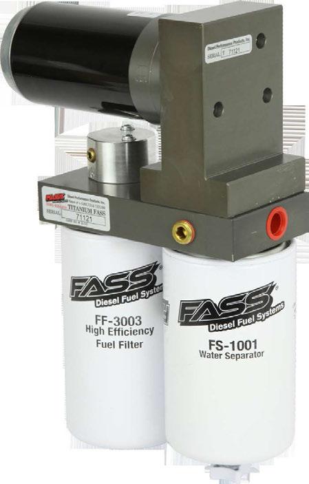
21 Step 7: Review Installation & Secure Connections Note: O-Ring must be put back on suction side of pump. Failure to do so can result in priming issues, cavitation, or pressure loses. Fuel Filter Install FF-3003 on side of pump with draw tube in the middle of the filter nipple. Water Separator Filter Install FS-1001 on water separator nipple without the draw tube. Make sure to insert O-Ring provided on nipple.
 Carquest 86528 (2M) Baldwin BF1214 CAT 1P2299 (6M) Baldwin BF7546 (10M) CAT 1R0750 (2M) Donaldson P558000 (20M) Donaldson P551025(4M) Donaldson P551000 (10M) Donaldson P551311")
 Fram P8334 (2M) Fleetguard FS-1212(14M) Hastings FF1079 (2M) LuberFiner LFF8011 Wix 33352 (6M) LuberFiner LFF8000 Wix 33528 (2M) Motorcraft FD818 (14M) Wix 33674 (2M) Wix")
22 Filter Cross References (Currently in use) Fuel (FWS-3003) Water (FS-1001) Fuel Filter (Micron Rating) Water Separator (Micron Rating) Thread Size (1-14) Thread Size (1-14) Baldwin BF7633 (2M) Baldwin BF 1258 (10M) Carquest (2M) Baldwin BF1214 CAT 1P2299 (6M) Baldwin BF7546 (10M) CAT 1R0750 (2M) Donaldson P (20M) Donaldson P551025(4M) Donaldson P (10M) Donaldson P (3M) Donaldson P551001(10M) Donaldson P (3M) Fleetguard FS1282 (14M) Donaldson P553203(3M) Fleetguard FS-1000 (10M) Donaldson P (6M) Fleetguard FS-1001 (10M) Fleetguard FF5320(2M) Fleetguard FS-1009(14M) Fram P8334 (2M) Fleetguard FS-1212(14M) Hastings FF1079 (2M) LuberFiner LFF8011 Wix (6M) LuberFiner LFF8000 Wix (2M) Motorcraft FD818 (14M) Wix (2M) Wix 33405(14M) Wix (10M)
INSTALLATION MANUAL APPLICATION: T D07 220G 16-18psi) T D07 260G 16-18psi) Cummins 5.9L /6.7L 24Valve Standard Pickup Truck
 T D07 260G 16-18psi) Cummins 5.9L /6.7L 24Valve Standard Pickup Truck") INSTALLATION MANUAL APPLICATION: T D07 220G (220GPH @ 16-18psi) T D07 260G (260GPH @ 16-18psi) Cummins 5.9L /6.7L 24Valve Standard Pickup Truck 2005-2016 1998.5-2004 *with In-tank Lift Pump* **Note: Cab
INSTALLATION MANUAL APPLICATION: T D07 220G (220GPH @ 16-18psi) T D07 260G (260GPH @ 16-18psi) Cummins 5.9L /6.7L 24Valve Standard Pickup Truck 2005-2016 1998.5-2004 *with In-tank Lift Pump* **Note: Cab
INSTALLATION MANUAL APPLICATION: T F16 95G 8-10psi) T F16 150G 8-10psi) Powerstroke 6.4L Standard Pickup Truck
 T F16 150G 8-10psi) Powerstroke 6.4L Standard Pickup Truck") INSTALLATION MANUAL APPLICATION: T F16 95G (95GPH @ 8-10psi) T F16 150G (150GPH @ 8-10psi) Powerstroke 6.4L Standard Pickup Truck 2008-2010 **Note: Cab and Chassis may require modifications** WARNINGs!
INSTALLATION MANUAL APPLICATION: T F16 95G (95GPH @ 8-10psi) T F16 150G (150GPH @ 8-10psi) Powerstroke 6.4L Standard Pickup Truck 2008-2010 **Note: Cab and Chassis may require modifications** WARNINGs!
WARNINGs! Read all instructions before starting installation of this product! Installing the improper FASS Pump can cause severe engine damage.
 WARNINGs! Read all instructions before starting installation of this product! Installing the improper FASS Pump can cause severe engine damage. FASS Recommended Application T F17 150G Powerstroke (6.7L)
INSTALLATION MANUAL APPLICATION: T C10 095G T C10 150G 8psi) Duramx 2500 &
 Duramx 2500 &") INSTALLATION MANUAL APPLICATION: T C10 095G (95gph @8psi) T C10 150G (150gph @ 8psi) Duramx 2500 & 3500 2006-2010 **Note: Cab and Chassis may require modifications** WARNINGs! Read all instructions before
INSTALLATION MANUAL APPLICATION: T C10 095G (95gph @8psi) T C10 150G (150gph @ 8psi) Duramx 2500 & 3500 2006-2010 **Note: Cab and Chassis may require modifications** WARNINGs! Read all instructions before
INSTALLATION MANUAL APPLICATION:
 INSTALLATION MANUAL APPLICATION: FA C09 220G (220GPH @ 12-14psi) FA C09 260G (2600GPH @ 12-14psi) Standard Pickup Truck Duramax 2500 & 3500 2001-2014 WARNINGS! Read all instructions before starting installation
INSTALLATION MANUAL APPLICATION: FA D08 095G FA D08 150G 16-18psi) Cummins 5.9L 24 Valve Standard Pickup Truck 1998.
 Cummins 5.9L 24 Valve Standard Pickup Truck 1998.") INSTALLATION MANUAL APPLICATION: FA D08 095G (95GPH @16-18psi) FA D08 150G (150GPH @ 16-18psi) Cummins 5.9L 24 Valve Standard Pickup Truck 1998.5-2004 WARNINGs! Read all instructions before starting installation
INSTALLATION MANUAL APPLICATION: FA D08 095G (95GPH @16-18psi) FA D08 150G (150GPH @ 16-18psi) Cummins 5.9L 24 Valve Standard Pickup Truck 1998.5-2004 WARNINGs! Read all instructions before starting installation
INSTALLATION MANUAL APPLICATION: T C10 095G 8-10psi) T C10 150G 8-10psi) Duramax 2500 & 3500 Standard Pickup Truck
 T C10 150G 8-10psi) Duramax 2500 & 3500 Standard Pickup Truck") INSTALLATION MANUAL APPLICATION: T C10 095G (95GPH @ 8-10psi) T C10 150G (150GPH @ 8-10psi) Duramax 2500 & 3500 Standard Pickup Truck 2001-2010 **Note: Cab and Chassis may require modifications** Revision
INSTALLATION MANUAL APPLICATION: T C10 095G (95GPH @ 8-10psi) T C10 150G (150GPH @ 8-10psi) Duramax 2500 & 3500 Standard Pickup Truck 2001-2010 **Note: Cab and Chassis may require modifications** Revision
INSTALLATION MANUAL APPLICATION: FA D07 095G 16-18psi) FA D07 150G 16-18psi) Cummins 5.9L/6.7L 24 Valve
 FA D07 150G 16-18psi) Cummins 5.9L/6.7L 24 Valve") INSTALLATION MANUAL APPLICATION: FA D07 095G (95GPH @ 16-18psi) FA D07 150G (150GPH @ 16-18psi) Cummins 5.9L/6.7L 24 Valve 2005-2009 *1998.5-2004 with In-tank Pump Modification* **2003-2004 must order
INSTALLATION MANUAL APPLICATION: FA D07 095G (95GPH @ 16-18psi) FA D07 150G (150GPH @ 16-18psi) Cummins 5.9L/6.7L 24 Valve 2005-2009 *1998.5-2004 with In-tank Pump Modification* **2003-2004 must order
INSTALLATION MANUAL AppLIcATION:
 INSTALLATION MANUAL Application: P D07 095G (95gph @ 16psi) P D07 150G (150gph @ 16psi) Cummins 5.9L /6.7L 24 Valve 2005-2012 *1998.5-2004 with In-tank Lift Pump* Dear Valued Customer, Made in the USA
Limited lifetime Warranty
 T D07 095G or T D07 165G Limited lifetime Warranty Motor No: Manufactured Date: Serial No: Warranty Stipulations: Copy of sales receipt mailed with this form All warranty information, located on the front
WARNINGs! Read all instructions before starting installation of this product! Installing the improper FASS Pump can cause severe engine damage.
 WARNINGs! Read all instructions before starting installation of this product! Installing the improper FASS Pump can cause severe engine damage. FASS T C12 095G T C12 150G Recommended Application Duramax
INSTALLATION MANUAL FASS FUEL SYSTEM MODEL NO. FASS 150/ & FASS 150/ HIGH PERFORMANCE FUEL DELIVERY SYSTEM
 INSTALLATION MANUAL MODEL NO. FASS 150/95-1007 & FASS 150/150-1007 HIGH PERFORMANCE FUEL DELIVERY SYSTEM FROM: SUBJECT: TO: Diesel Performance Products, Inc. Welcome/Thank You Valued Customer We at Diesel
INSTALLATION MANUAL APPLICATION: T D02 095G 8-10psi) T D02 150G 8-10psi) Cummins 5.9L 12 Valve *with VE Pump*
 T D02 150G 8-10psi) Cummins 5.9L 12 Valve *with VE Pump*") INSTALLATION MANUAL APPLICATION: T D02 095G (95GPH @ 8-10psi) T D02 150G (150GPH @ 8-10psi) Cummins 5.9L 12 Valve *with VE Pump* 1989-1993 Dear Valued Customer, Made in the USA is not just a slogan at
INSTALLATION MANUAL APPLICATION: T D02 095G (95GPH @ 8-10psi) T D02 150G (150GPH @ 8-10psi) Cummins 5.9L 12 Valve *with VE Pump* 1989-1993 Dear Valued Customer, Made in the USA is not just a slogan at
INSTALLATION MANUAL APPLICATION: T D07 095G 16psi) T D07 150G 16psi) Cummins 5.9L/6.7L 24 Valve
 T D07 150G 16psi) Cummins 5.9L/6.7L 24 Valve") INSTALLATION MANUAL APPLICATION: T D07 095G (95gph @ 16psi) T D07 150G (150gph @ 16psi) Cummins 5.9L/6.7L 24 Valve 2005-2015 1998.5-2004 *with In-tank Lift Pump* **Note: Cab and Chassis may require modifications**
INSTALLATION MANUAL APPLICATION: T D07 095G (95gph @ 16psi) T D07 150G (150gph @ 16psi) Cummins 5.9L/6.7L 24 Valve 2005-2015 1998.5-2004 *with In-tank Lift Pump* **Note: Cab and Chassis may require modifications**
INSTALLATION MANUAL. 220 gph (T D08 220G) Cummins 5.9L 24 Valve REVISED 4/05/11
 Cummins 5.9L 24 Valve REVISED 4/05/11") INSTALLATION MANUAL Application: 220 gph (T D08 220G) Cummins 5.9L 24 Valve 1998.5-2004 REVISED 4/05/11 Dear Valued Customer, Made in the USA is not just a slogan at FASS; it s what we live by! FASS is
INSTALLATION MANUAL Application: 220 gph (T D08 220G) Cummins 5.9L 24 Valve 1998.5-2004 REVISED 4/05/11 Dear Valued Customer, Made in the USA is not just a slogan at FASS; it s what we live by! FASS is
INSTALLATION MANUAL APPLICATION: T D08 095G 16-18psi) T D08 150G 16-18psi) Cummins 5.9L 24 Valve
 T D08 150G 16-18psi) Cummins 5.9L 24 Valve") INSTALLATION MANUAL APPLICATION: T D08 095G (95GPH @ 16-18psi) T D08 150G (150GPH @ 16-18psi) Cummins 5.9L 24 Valve 1998.5-2004 **Note: Cab and Chassis may require modifications** Dear Valued Customer,
INSTALLATION MANUAL APPLICATION: T D08 095G (95GPH @ 16-18psi) T D08 150G (150GPH @ 16-18psi) Cummins 5.9L 24 Valve 1998.5-2004 **Note: Cab and Chassis may require modifications** Dear Valued Customer,
INSTALLATION MANUAL APPLICATION: T D10 125G 45psi) Cummins 5.9L 12Valve *with P7100 Injection Pump*
 Cummins 5.9L 12Valve *with P7100 Injection Pump*") INSTALLATION MANUAL APPLICATION: T D10 125G (125GPH @ 45psi) Cummins 5.9L 12Valve *with P7100 Injection Pump* 1994-1998 **Note: Cab and Chassis may require modifications** Dear Valued Customer, Made in
INSTALLATION MANUAL APPLICATION: T D10 125G (125GPH @ 45psi) Cummins 5.9L 12Valve *with P7100 Injection Pump* 1994-1998 **Note: Cab and Chassis may require modifications** Dear Valued Customer, Made in
INSTALLATION MANUAL STK-5500BO ACCESSORY: Sump Kit
 INSTALLATION MANUAL STK-5500BO ACCESSORY: Sump Kit INSTALLATION MANUAL Follow these steps to ensure a simple installation of your new FASS ACCESSORY 1. Read the installation manual completely before attempting
INSTALLATION MANUAL APPLICATION: T F16 220G 8-10psi) Powerstroke 6.4L **Note: Cab and Chassis may require modifications**
 Powerstroke 6.4L **Note: Cab and Chassis may require modifications**") INSTALLATION MANUAL APPLICATION: T F16 220G (220GPH @ 8-10psi) Powerstroke 6.4L 2008-2010 **Note: Cab and Chassis may require modifications** Dear Valued Customer, Made in the USA is not just a slogan
INSTALLATION MANUAL APPLICATION: T F16 220G (220GPH @ 8-10psi) Powerstroke 6.4L 2008-2010 **Note: Cab and Chassis may require modifications** Dear Valued Customer, Made in the USA is not just a slogan
INSTALLATION MANUAL TITANIUM SIGNATURE SERIES ALL 1/2 FUEL PORTS LIFETIME WARRANTY AVAILABLE APPLICATION: Cummins 5.9L 24 Valve
 TITANIUM SIGNATURE SERIES INSTALLATION MANUAL ALL 1/2 FUEL PORTS APPLICATION: TS-D08-250G (250GPH @ 16-18PSI) TS-D08-290G (290G @ 16-18PSI) Cummins 5.9L 24 Valve Standard Pickup Truck 1998.5-2004 LIFETIME
INSTALLATION MANUAL TITANIUM SIGNATURE SERIES ALL 1/2 FUEL PORTS LIFETIME WARRANTY AVAILABLE. Manufacture Date: APPLICATION: Cummins 5.
 Manufacture Date: TITANIUM SIGNATURE SERIES INSTALLATION MANUAL ALL 1/2 FUEL PORTS APPLICATION: TS-D08-250G (250GPH @ 16-18PSI) TS-D08-290G (290G @ 16-18PSI) Cummins 5.9L 24 Valve Standard Pickup Truck
INSTALLATION MANUAL TITANIUM SERIES ALL 1/2 FUEL PORTS LIFETIME WARRANTY AVAILABLE DURAMAX 2500 & 3500 APPLICATION:
 TITANIUM SERIES INSTALLATION MANUAL ALL 1/2 FUEL PORTS APPLICATION: TS-C11-095G (95GPH @ 8-10PSI) TS-C11-165G (165GPH @ 8-10PSI) DURAMAX 2500 & 3500 Standard Pickup Truck 2011-2014 *NOTE: CAB AND CHASSIS
INSTALLATION MANUAL TITANIUM SERIES ALL 1/2 FUEL PORTS LIFETIME WARRANTY AVAILABLE DURAMAX 2500 & 3500 APPLICATION:
 TITANIUM SERIES INSTALLATION MANUAL ALL 1/2 FUEL PORTS APPLICATION: TS-C10-095G (95GPH @ 8-10PSI) TS-C10-165G (165GPH @ 8-10PSI) DURAMAX 2500 & 3500 Standard Pickup Truck 2001-2010 *NOTE: CAB AND CHASSIS
Limited lifetime Warranty
 T C10 095G or T C10 165G Limited lifetime Warranty Motor No: Manufactured Date: Serial No: Warranty Stipulations: Copy of sales receipt mailed with this form All warranty information, located on the front
INSTALLATION MANUAL TITANIUM SERIES ALL 1/2 FUEL PORTS LIFETIME WARRANTY AVAILABLE APPLICATION: Cummins 5.9L/6.7L 24 Valve
 TITANIUM SERIES INSTALLATION MANUAL ALL 1/2 FUEL PORTS APPLICATION: TS-D07-095G (95GPH @ 16-18PSI) TS-D07-165G (165GPH @16-18PSI) Cummins 5.9L/6.7L 24 Valve Standard Pickup Truck 2005-2017 1998.5-2004
INSTALLATION MANUAL APPLICATION: FA D10 240G 45psi) Cummins 5.9L 12 Valve *With P7100 Injection pump* **bypassing the factory lift pump**
 Cummins 5.9L 12 Valve *With P7100 Injection pump* **bypassing the factory lift pump**") INSTALLATION MANUAL APPLICATION: FA D10 240G (240gph @ 45psi) Cummins 5.9L 12 Valve *With P7100 Injection pump* **bypassing the factory lift pump** 1994-1998 Dear Valued Customer, Made in the USA is not
INSTALLATION MANUAL APPLICATION: FA D10 240G (240gph @ 45psi) Cummins 5.9L 12 Valve *With P7100 Injection pump* **bypassing the factory lift pump** 1994-1998 Dear Valued Customer, Made in the USA is not
INSTALLATION MANUAL APPLICATION: T F14 125G 55psi) Powerstroke 7.3L *Bypassing the Factory Lift Pump*
 Powerstroke 7.3L *Bypassing the Factory Lift Pump*") INSTALLATION MANUAL APPLICATION: T F14 125G (125GPH @ 55psi) Powerstroke 7.3L *Bypassing the Factory Lift Pump* 1999-2003 Powerstroke 6.0L *Bypassing the Factory Lift Pump* 2003-2007 **Note: Cab and Chassis
INSTALLATION MANUAL APPLICATION: T F14 125G (125GPH @ 55psi) Powerstroke 7.3L *Bypassing the Factory Lift Pump* 1999-2003 Powerstroke 6.0L *Bypassing the Factory Lift Pump* 2003-2007 **Note: Cab and Chassis
INSTALLATION MANUAL APPLICATION: D-MAX psi) Duramax Fuel Pump
 Duramax Fuel Pump") INSTALLATION MANUAL APPLICATION: D-MAX 7001 (120GPH @ 8-10psi) Duramax Fuel Pump 2001-2010 Dear Valued Customer, Made in the USA is not just a slogan at FASS; it s what we live by! FASS is not only assembled
INSTALLATION MANUAL APPLICATION: D-MAX 7001 (120GPH @ 8-10psi) Duramax Fuel Pump 2001-2010 Dear Valued Customer, Made in the USA is not just a slogan at FASS; it s what we live by! FASS is not only assembled
INSTALLATION MANUAL TITANIUM SERIES ALL 1/2 FUEL PORTS LIFETIME WARRANTY AVAILABLE CUMMINS 5.9L 24 VALVE APPLICATION:
 TITANIUM SERIES INSTALLATION MANUAL ALL 1/2 FUEL PORTS APPLICATION: TS-D08-095G (95GPH @ 16-18PSI) TS-D08-165G (165GPH @16-18PSI) CUMMINS 5.9L 24 VALVE 1998.5-2004 LIFETIME WARRANTY AVAILABLE FASS DIESEL
HIGH PERFORMANCE FUEL PUMP
 MODEL NO. FASS-HPFP-95-1003 & FASS-HPFP-150-1003 HIGH PERFORMANCE FUEL PUMP A MUST READ FROM: SUBJECT: TO: Diesel Performance Products, Inc. Welcome/Thank You Valued Customer We at Diesel Performance Products,
INSTALLATION MANUAL APPLICATION: DRP psi) Dodge Replacement
 Dodge Replacement") INSTALLATION MANUAL APPLICATION: DRP 02 (110GPH @ 16-18psi) Dodge Replacement 1998.5-2002 WARNINGs! Read all instructions before starting installation of this product! Installing the improper FASS Pump
INSTALLATION MANUAL APPLICATION: DRP 02 (110GPH @ 16-18psi) Dodge Replacement 1998.5-2002 WARNINGs! Read all instructions before starting installation of this product! Installing the improper FASS Pump
INSTALLATION MANUAL TITANIUM SIGNATURE SERIES ALL 1/2 FUEL PORTS LIFETIME WARRANTY AVAILABLE. Manufacture Date:
 Manufacture Date: TITANIUM SIGNATURE SERIES INSTALLATION MANUAL ALL 1/2 FUEL PORTS APPLICATION: TS-F17-125G (125GPH @ 70-75PSI) Powerstroke 6.7L *Bypassing the Factory Lift Pump* Standard Pickup Truck
INSTALLATION MANUAL TITANIUM SIGNATURE SERIES ALL 1/2 FUEL PORTS LIFETIME WARRANTY AVAILABLE APPLICATION: Cummins 5.9L/6.
 TITANIUM SIGNATURE SERIES INSTALLATION MANUAL ALL 1/2 FUEL PORTS APPLICATION: TS-D07-095G (95GPH @ 16-18PSI) TS-D07-165G (165GPH @16-18PSI) Cummins 5.9L/6.7L 24 Valve Standard Pickup Truck 2005-2017 1998.5-2004
INSTALLATION MANUAL TITANIUM SERIES ALL 1/2 FUEL PORTS LIFETIME WARRANTY AVAILABLE APPLICATION:
 TITANIUM SERIES INSTALLATION MANUAL ALL 1/2 FUEL PORTS APPLICATION: TS-C12-095G (95GPH @ 8-10PSI) TS-C12-165G (165GPH @ 8-10PSI) GM DURAMAX 2015-2016 *NOTE: CAB AND CHASSIS MAY REQUIRE MODIFICATIONS LIFETIME
INSTALLATION MANUAL APPLICATION: FA C09 220G 12-14psi) FA C09 260G 12-14psi) Standard Pickup Truck Duramax 2500 &
 FA C09 260G 12-14psi) Standard Pickup Truck Duramax 2500 &") INSTALLATION MANUAL APPLICATION: FA C09 220G (220GPH @ 12-14psi) FA C09 260G (2600GPH @ 12-14psi) Standard Pickup Truck Duramax 2500 & 3500 2001-2014 Revision Date: 10/12/2015 Dear Valued Customer, Made
INSTALLATION MANUAL APPLICATION: FA C09 220G (220GPH @ 12-14psi) FA C09 260G (2600GPH @ 12-14psi) Standard Pickup Truck Duramax 2500 & 3500 2001-2014 Revision Date: 10/12/2015 Dear Valued Customer, Made
INSTALLATION MANUAL STK-5500BO ACCESSORY: Sump Kit
 INSTALLATION MANUAL STK-5500BO ACCESSORY: Sump Kit Dear Valued Customer, Made in the USA is not just a slogan at FASS; it s what we live by! FASS is not only assembled in the USA but 98%+ of the FASS product
L DODGE CUMMINS MK-2 High Flow Fuel Filter Kit
 Installation Manual P/N MK21318-BLK (non-heated) P/N MK21318-BLKH (heated) 2013-2018 6.7L DODGE CUMMINS MK-2 High Flow Fuel Filter Kit Installation Instructions P/N MK21318-BLK (non-heated) P/N MK21318-BLKH
INSTALLATION MANUAL ACCESSORY:
 INSTALLATION MANUAL ACCESSORY: No Drill Bolt on Bracket Kit Dodge Cummins 1989-1993 Ford Powerstroke 1999-2012 Dear Valued Customer, Made in the USA is not just a slogan at FASS; it s what we live by!
INSTALLATION MANUAL STK ACCESSORY: Suction Tube Kit SUMP
 INSTALLATION MANUAL STK-5500 ACCESSORY: Suction Tube Kit SUMP Dear Valued Customer, Made in the USA is not just a slogan at FASS; it s what we live by! FASS is not only assembled in the USA but 98%+ of
AEROMOTIVE Part # FORD POWERSTROKE Fuel System Kit INSTALLATION INSTRUCTIONS
 AEROMOTIVE Part # 11807 08-10 FORD POWERSTROKE Fuel System Kit INSTALLATION INSTRUCTIONS CAUTION: Installation of this product requires detailed knowledge of automotive systems and repair procedures. We
INSTALLATION MANUAL ACCESSORY:
 INSTALLATION MANUAL ACCESSORY: No Drill Bolt on Bracket Kit Dodge Cummins 1994-2012 GM Duramax 2001-2012 Dear Valued Customer, Made in the USA is not just a slogan at FASS; it s what we live by! FASS is
INSTALLATION MANUAL TITANIUM SIGNATURE SERIES ALL 1/2 FUEL PORTS LIFETIME WARRANTY AVAILABLE APPLICATION: TS-F18-125G 65PSI)
") TITANIUM SIGNATURE SERIES INSTALLATION MANUAL ALL 1/2 FUEL PORTS APPLICATION: TS-F18-125G (125GPH @ 65PSI) Powerstroke 6.7L *Bypassing the Factory Lift Pump* Standard Pickup Truck 2017-2019 LIFETIME WARRANTY
TITANIUM SIGNATURE SERIES INSTALLATION MANUAL ALL 1/2 FUEL PORTS APPLICATION: TS-F18-125G (125GPH @ 65PSI) Powerstroke 6.7L *Bypassing the Factory Lift Pump* Standard Pickup Truck 2017-2019 LIFETIME WARRANTY
Auxiliary Transmission Filter Kit
 19 July 2012 Dodge Transmission Filter Kit # 1064017-1 - Auxiliary Transmission Filter Kit Part # Vehicle Application 1064017 Dodge 1994-2007 The BD Transmission Filter Kit will provide added security
FORD POWERSTROKE 6.0L DIESEL ENGINE
 #8 INSTALLATION MANUAL MODEL FP-100 & FP-150 With New Quick Connect Components! 2003-2007 FORD POWERSTROKE 6.0L DIESEL ENGINE Performance Fuel System Parts PLEASE READ THESE INSTRUCTIONS THOROUGHLY BEFORE
FASSRIDE.COM THE FUTURE OF FUEL
 FASSRIDE.COM THE FUTURE OF FUEL REMOVES ALL TYPES OF CONTAMINANTS & SAVES YOUR INJECTORS CONSISTENT ENGINE PERFORMANCE-HOT VS. COLD FUEL & FULL VS. QUARTER TANK INCREASE HORSEPOWER & TORQUE LOWER MAINTENANCE
INSTALLATION MANUAL APPLICATION: DRP psi) Dodge Replacement
 Dodge Replacement") INSTALLATION MANUAL APPLICATION: DRP 02 (110GPH @ 16-18psi) Dodge Replacement 1998.5-2002 Dear Valued Customer, Made in the USA is not just a slogan at FASS; it s what we live by! FASS is not only assembled
INSTALLATION MANUAL APPLICATION: DRP 02 (110GPH @ 16-18psi) Dodge Replacement 1998.5-2002 Dear Valued Customer, Made in the USA is not just a slogan at FASS; it s what we live by! FASS is not only assembled
INSTALLATION MANUAL STK-1003B & STK Suction Tube Kit Dodge Cummins Ford Powerstroke GM Duramax
 INSTALLATION MANUAL STK-1003B & STK-1003 Suction Tube Kit Dodge Cummins 1989-2012 Ford Powerstroke 1999-2012 GM Duramax 2001-2012 Dear Valued Customer, Made in the USA is not just a slogan at FASS; it
INSTALLATION MANUAL APPLICATION: DRP psi) Dodge Replacement
 Dodge Replacement") INSTALLATION MANUAL APPLICATION: DRP 04 (110GPH @ 16-18psi) Dodge Replacement 2003-2004 Dear Valued Customer, Made in the USA is not just a slogan at FASS; it s what we live by! FASS is not only assembled
INSTALLATION MANUAL APPLICATION: DRP 04 (110GPH @ 16-18psi) Dodge Replacement 2003-2004 Dear Valued Customer, Made in the USA is not just a slogan at FASS; it s what we live by! FASS is not only assembled
HP10134 & HP10135 KITS BASIC SIMULTANEOUS AIR SPRING ACTIVATION KIT
 HP10134 & HP10135 KITS BASIC SIMULTANEOUS AIR SPRING ACTIVATION KIT Thank you and congratulations on the purchase of a Pacbrake simultaneous air spring activation kit. This kit was designed to add in-cab
INDUSTRIAL. For All Model Years CUMMINS N-14 Diesel Engines With Remote Mount Primary Fuel Filter
 INDUSTRIAL Fuel Air Separation System INSTALLATION MANUAL For All Model Years CUMMINS N-14 Diesel Engines With Remote Mount Primary Fuel Filter PLEASE READ THESE INSTRUCTIONS THOROUGHLY BEFORE BEGINNING
INSTALLATION INSTRUCTIONS
 28 INSTALLATION INSTRUCTIONS SECTION - AIR SPRING SECTION 2 - AIR ACCESSORY 2-5 ! IMPORTANT PLEASE DON T HURT YOURSELF, YOUR KIT OR YOUR VEHICLE. TAKE A MINUTE TO READ THIS IMPORTANT INFORMATION. This
INSTALLATION INSTRUCTIONS
 2807 INSTALLATION INSTRUCTIONS SECTION - AIR SPRING SECTION 2 - AIR ACCESSORY -6 ! IMPORTANT PLEASE DON T HURT YOURSELF, YOUR KIT OR YOUR VEHICLE. TAKE A MINUTE TO READ THIS IMPORTANT INFORMATION. This
INDUSTRIAL. Providing Test Cell Performance in Real World Conditions Since 1993!
 INDUSTRIAL Fuel Air Separation System INSTALLATION MANUAL For Trucks Equipped with CATERPILLAR 3406 A, B, or C Engines Kit No. A3SPBT401 NOW WITH DEMAND FLOW Revised 2/24/17 Proudly Made in the USA www.pureflowtechnologies.com
INDUSTRIAL. INSTALLATION MANUAL For Trucks Equipped with the VOLVO VED-12 & D13 ENGINES
 INDUSTRIAL Fuel Air Separation System INSTALLATION MANUAL For Trucks Equipped with the VOLVO VED-12 & D13 ENGINES PLEASE READ THESE INSTRUCTIONS THOROUGHLY BEFORE BEGINNING INSTALLATION Kit No. A3SPBT406
System Flow Diagram. Starting the engine. Filter Maintenance
 The FASS Fuel System is a positive flow, fuel delivery system for diesel engines. It has been designed to remove all types of fuel contaminants such as air/vapor, water, dirt and particulate from diesel
PRODUCT SAFETY NOTICE
 PRODUCT SAFETY NOTICE Congratulations. This vehicle has been equipped with a Firestone air suspension system. This suspension will enhance the vehicle s handling when loaded, however, the vehicle s performance
INSTALLATION MANUAL SFB-1001 ACCESSORY: SEMI Frame Bracket
 INSTALLATION MANUAL SFB-1001 ACCESSORY: SEMI Frame Bracket Dear Valued Customer, Made in the USA is not just a slogan at FASS; it s what we live by! FASS is not only assembled in the USA but 98%+ of the
advanced FLOW engineering Instruction Manual P/N: Make: Dodge Model: 2500 / 3500 Year: Engine: I-6 5.9L (td)
") advanced FLOW engineering Instruction Manual P/N: 42-22011 DFS780 PRO Make: Dodge Model: 2500 / 3500 Year: 1998.5-2002 Engine: I-6 5.9L (td) 1 Label Qty. Description Part Number A 1 Fuel Manifold Assembly
advanced FLOW engineering Instruction Manual P/N: 42-22011 DFS780 PRO Make: Dodge Model: 2500 / 3500 Year: 1998.5-2002 Engine: I-6 5.9L (td) 1 Label Qty. Description Part Number A 1 Fuel Manifold Assembly
7.3L Ford PowerStroke 1999 THROUGH 2003 Without a Mechanical Lift Pump
 INSTALLATION MANUAL #34 7.3L Ford PowerStroke 1999 THROUGH 2003 Without a Mechanical Lift Pump MODEL RP-150 High Pressure Lift Pump With New Quick Connect Components! PLEASE READ THESE INSTRUCTIONS THOROUGHLY
BEFORE BEGINNING INSTALLATION
 COMPLETE CHASSIS FUEL LINE KITS For 1996-2000 Honda Civic Equipped with B-Series Engine INSTALLATION INSTRUCTIONS PLEASE study these instructions carefully before beginning this installation. Most installations
AEROMOTIVE Part # Street Rod Fuel Pump System INSTALLATION INSTRUCTIONS
 AEROMOTIVE Part # 17201 Street Rod Fuel Pump System INSTALLATION INSTRUCTIONS CAUTION: Installation of this product requires detailed knowledge of automotive systems and repair procedures. We recommend
CAUTIONS AND WARNINGS
 FIREWALL FORWARD FUEL LINE KITS For 1996-2000 Honda Civic Equipped with B-Series Engine INSTALLATION INSTRUCTIONS PLEASE study these instructions carefully before beginning this installation. Most installations
INSTALLATION AND USER MANUAL
 INSTALLATION AND USER MANUAL SDKIT-730 & SDKIT-734 100% Bolt-On 150 PSI Train Horn System for 2011-2015 F-250 & F-350 Super Duty P/N SDKIT-730 P/N SDKIT-734 Thank you for purchasing a Kleinn Air Horns
READ INSTRUCTIONS COMPLETELY BEFORE BEGINNING INSTALLATION
 INSTALLATION INSTRUCTIONS Hot Fox In-Tank Fuel Warmer READ INSTRUCTIONS COMPLETELY BEFORE BEGINNING INSTALLATION Models covered by these instructions include: HFG 0-0 HFG 0- SHFT--0- SHH--0 TWHF 0- HFG
INSTALLATION MANUAL RK-1002 ACCESSORY: Relocation Kit DDRP 02
 INSTALLATION MANUAL RK-1002 ACCESSORY: Relocation Kit DDRP 02 Dodge Cummins 1998.5-2002 Contents FL-1001 x14 FB-4001 WE-1007 FF-3270 HC-1001 PL-1003 DIPF-1001 QD-1001 Self Tapping Screw Before you get
INDUSTRIAL. INSTALLATION MANUAL DETROIT SERIES 60 ENGINES Model Years Providing Test Cell Performance in Real World Conditions Since 1993!
 INDUSTRIAL Fuel Air Separation System INSTALLATION MANUAL DETROIT SERIES 60 ENGINES Model Years 1987-2002 PLEASE READ THESE INSTRUCTIONS THOROUGHLY BEFORE BEGINNING INSTALLATION Part No. A3SPBT405 NOW
ELECTRIC FUEL PUMPS P/N , , & FUEL PRESSURE REGULATOR P/N
 ELECTRIC FUEL PUMPS P/N 80000100, 80000101, & 80000102 FUEL PRESSURE REGULATOR P/N 80000103 Installation Instructions 199R10583 These instructions must be read and fully understood before beginning the
DESCRIPTION MECHANICAL FUEL PUMP FUEL FILTER HIGH PRESSURE (35-90 PSI) HIGH PRESSURE (35-90 PSI) (STEEL/INCLUDED)
 HIGH PRESSURE (35-90 PSI) (STEEL/INCLUDED)") Edelbrock EFI Universal Fuel Sump System - Adjustable Part #36031, 36032, 36033, 36034 INSTALLATION INSTRUCTIONS PLEASE study these instructions carefully before beginning this installation. This installation
Edelbrock EFI Universal Fuel Sump System - Adjustable Part #36031, 36032, 36033, 36034 INSTALLATION INSTRUCTIONS PLEASE study these instructions carefully before beginning this installation. This installation
KIT CONTENTS. Multimeter or test light Wire crimpers or soldering equipment. Wire terminals & connectors 10A inline fuse
 RUSSELL FORD 5.0L COMPLETE EFI PLUMBING KIT INSTALLATION INSTRUCTIONS Please study these instructions carefully before installing your new complete fuel system kit. If you have any questions, please call
INSTALLATION INSTRUCTIONS
 2581 INSTALLATION INSTRUCTIONS 08-15 IMPORTANT PLEASE DON T HURT YOURSELF, THE KIT, OR YOUR VEHICLE. TAKE A MINUTE TO READ THIS IMPORTANT INFORMATION. SAFE INSTALLATION Please take all safety precautions
PRODUCT SAFETY NOTICE DEALER/INSTALLER NOTICE
 PRODUCT SAFETY NOTICE Congratulations. This vehicle has been equipped with a Firestone air suspension system. This suspension will enhance the vehicle s handling when loaded, however, the vehicle s performance
CUMMINS 6.7L EXHAUST BRAKE PRXB EXHAUST BRAKE KIT FOR 2007½-2015 TRUCKS EQUIPPED WITH 6.7L CUMMINS ISB DIESEL ENGINES. C Kit C Kit
 CUMMINS 6.7L EXHAUST BRAKE PRXB EXHAUST BRAKE KIT FOR 2007½-2015 TRUCKS EQUIPPED WITH 6.7L CUMMINS ISB DIESEL ENGINES C44038 4 Kit C44039 5 Kit BEFORE STARTING THE INSTALLATION please read the entire installation
Xtreme Air Command. Step 1 Prepare the components. Step 2 Select a mounting location. Parts list
 2549 60 90 400 600 30 200 120 800 psi 1000 kpa PSI 0 150 Xtreme Air Command Installation instructions Congratulations on your purchase of a new Xtreme Air Command kit. This kit was designed to provide
AEROMOTIVE Part # CHEVY/GMC Duramax Fuel System Kit RETRO FIT KIT FOR ½ LINES INSTALLATION INSTRUCTIONS
 AEROMOTIVE Part # 11803 01-10 CHEVY/GMC Duramax Fuel System Kit RETRO FIT KIT FOR ½ LINES INSTALLATION INSTRUCTIONS CAUTION: Installation of this product requires detailed knowledge of automotive systems
Thank You. for purchasing an Edelbrock Nitrous Oxide Injection System. Please take the time to read and understand the following.
 Thank You. for purchasing an Edelbrock Nitrous Oxide Injection System. Nitrous Oxide injection is one of the most exciting performance enhancements for the dollar invested on the market today. With the
The FASS Fuel System is a positive flow, fuel delivery system for diesel engines.
 The FASS Fuel System is a positive flow, fuel delivery system for diesel engines. It has been designed to remove all types of fuel contaminants such as air/vapor, water, dirt and particulate from diesel
INSTALLATION MANUAL. CUMMINS POWERED DODGE TRUCKS Model Year 1994 THROUGH High Performance Fuel System! With New Quick Connect Components!
 #2 MODEL FP-100 & FP-150 INSTALLATION MANUAL CUMMINS POWERED DODGE TRUCKS Model Year 1994 THROUGH 1998 High Performance Fuel System! With New Quick Connect Components! READ INSTRUCTIONS THOROUGHLY BEFORE
# and # FAST Fuel System Kits
 1 INSTRUCTIONS #307500 and #307501 Fuel System Kits Thank you for choosing products; we are proud to be your manufacturer of choice. Please read this instruction sheet carefully before beginning the installation.
HP10098 BASIC INDEPENDENT AIR SPRING ACTIVATION KIT
 HP10098 BASIC INDEPENDENT AIR SPRING ACTIVATION KIT Thank you and congratulations on the purchase of a Pacbrake basic independent air spring activation kit. Please read the entire installation manual prior
Installation Manual P / P / P A / P B / P C E N G I N E B R A K E S
 Manual A p p l i c a t i o n : D e t r o i t D i e s e l S e r i e s 6 0 P - 6 1 / P - 6 3 / P - 6 3 A / P - 6 3 B / P - 6 3 C E N G I N E B R A K E S 5 If the engine is equipped with an aluminum valve
INSTALL MANUAL D o d g e 1 2 v 6 B T A PLEASE READ ALL INSTRUCTIONS BEFORE INSTALLATION.
 PN#1045310 12V Dodge Twin Turbo Kit (I-00273) 1 INSTALL MANUAL BD Twin Turbo Kit 1994-1 9 9 8 D o d g e 1 2 v 6 B T A Part# 1045310 PLEASE READ ALL INSTRUCTIONS BEFORE INSTALLATION. * Picture as shown
advanced FLOW engineering Instruction Manual P/N: Make: RAM Model: 1500 EcoDiesel Year: Engine: V-6 3.0L (td)
") advanced FLOW engineering Instruction Manual P/N: 42-22041 DFS780 PRO Make: RAM Model: 1500 EcoDiesel Year: 2014-2016 Engine: V-6 3.0L (td) 1 Label Qty. Description Part Number A 1 Fuel Manifold Assembly
advanced FLOW engineering Instruction Manual P/N: 42-22041 DFS780 PRO Make: RAM Model: 1500 EcoDiesel Year: 2014-2016 Engine: V-6 3.0L (td) 1 Label Qty. Description Part Number A 1 Fuel Manifold Assembly
Installation Manual v1.0: Force Cool Kit Dodge with NV4500/NV4500HD/NV5600 Manual Transmissions. Please read all instructions before installation.
 Installation Manual v1.0: Force Cool Kit Dodge with NV4500/NV4500HD/NV5600 Manual Transmissions Please read all instructions before installation. Figure 1 - Force Cool Kit Note: Use Teflon sealing tape
Edelbrock EFI Universal Fuel Sump System - Adjustable Part #36031, INSTALLATION INSTRUCTIONS
 Edelbrock EFI Universal Fuel Sump System - Adjustable Part #36031, 36032 INSTALLATION INSTRUCTIONS PLEASE study these instructions carefully before beginning this installation. This installation can be
advanced FLOW engineering Instruction Manual P/N: Make: Ford Model: Diesel Trucks Year: Engine: V8-7.3L (td)
") advanced FLOW engineering Instruction Manual P/N: 42-13011 Make: Ford Model: Diesel Trucks Year: 1999-2003 Engine: V8-7.3L (td) Please read the entire instruction manual before proceeding. Ensure all components
advanced FLOW engineering Instruction Manual P/N: 42-13011 Make: Ford Model: Diesel Trucks Year: 1999-2003 Engine: V8-7.3L (td) Please read the entire instruction manual before proceeding. Ensure all components
AEROMOTIVE Part # HP Hot Rod EFI Kit INSTALLATION INSTRUCTIONS
 AEROMOTIVE Part # 17150 700HP Hot Rod EFI Kit INSTALLATION INSTRUCTIONS CAUTION: Installation of this product requires detailed knowledge of automotive systems and repair procedures. We recommend that
C44090 HP325 PACBRAKE COMPRESSOR CONVERSION
 C44090 HP325 PACBRAKE COMPRESSOR CONVERSION APPLICATIONS: DODGE 2003-2007 5.9L CUMMINS Compressor Replacement Instructions for C14030, C14045, C44030, C44045, C44049 & C44052 with Air Tank KIT CONTENTS
MODEL NO & UP MODEL NO & UP MODEL NO & UP MODEL NO & UP
 MODEL NO. -900 & UP MODEL NO. 00-900 & UP MODEL NO. 0-900 & UP MODEL NO. 0-900 & UP SKID SPRAYER FORM NO. 99-055 REV. B SET-UP AND PARTS LIST Refer to the illustrated Parts List for the details of parts
Installation Manual v1.2: LLY / LBZ/LMM Twin CP3 Kit GM Duramax. Please read all instructions before installation.
 03/24/09 701-900-4290 - INST Installation Manual v1.2: LLY / LBZ/LMM Twin CP3 Kit 04.5-07.5 GM Duramax Please read all instructions before installation. This kit is not emissions legal in California. Kit
FUEL PREPORATOR FPII-150 The Original Fuel Air Separation System INSTALLATION MANUAL
 FUEL PREPORATOR FPII-150 The Original Fuel Air Separation System INSTALLATION MANUAL PLEASE READ THESE INSTRUCTIONS THOROUGHLY BEFORE BEGINNING THE INSTALLATION. Caterpillar 3406A, 3406B, 3406C, C7, C9,
Irate Diesel Regulated Return install:
 Irate Diesel Regulated Return install: 1. Remove IC piping and intake Y. It may also be easier to remove the Downpipe and turbo to gain access to the back fittings. This will depend upon how much you want
Duramax Lift Pump Kit 9-11 PSI Installation Instructions P/N# D
 2001-10 Duramax Lift Pump Kit 9-11 PSI Installation Instructions P/N# 1050320D PLEASE READ ALL INSTRUCTIONS CAREULLY BEORE INSTALLATION Kit Contents 1500365-P2 1500330-D lowmax Lift Pump V3 lowmax Wiring
ONBOARD AIR SYSTEM FOR ALL VEHICLES APPLICATIONS
 ONBOARD SYSTEM FOR ALL VEHICLES APPLICATIONS Thank you and congratulations on the purchase of a Pacbrake onboard air system. Please read the manual prior to starting to ensure you can complete the installation
DOMINATOR FUEL PUMPS P/N & Installation Instructions 199R10573
 DOMINATOR FUEL PUMPS P/N 12-1400 & 12-1800 Installation Instructions 199R10573 WARNING! THESE INSTRUCTIONS MUST BE READ AND FULLY UNDERSTOOD BEFORE BEGINNING INSTALLATION. FAILURE TO FOLLOW THESE INSTRUCTIONS
C WD 2 WHEEL LOW KIT FOR DODGE RAM 4WD VEHICLES
 C18056-4WD 2 WHEEL LOW KIT FOR 1994-2002 DODGE RAM 4WD VEHICLES Pacbrake s 4WD 2 Wheel Low Kit allows the vehicle operator to engage the transfer case into 4WD low range without engaging the front wheel
Mechanical Lift Pump System
 Installation Manual FUEL BOSS Mechanical LP P/N FB-03045 2003 2004.5 DODGE CUMMINS FUEL BOSS Mechanical Lift Pump System Installation Instructions Fuel Boss LP System p/n FB-03045 PLEASE READ ALL INSTRUCTIONS
Installation Instructions
 Installation Instructions for 15912 to 15916 Electric Fuel Pumps & Fuel Pressure Regulators Installation Instructions WARNING! These instructions must be read and fully understood before beginning the
AEROMOTIVE Part # Mustang 5.0L Fuel System Kit INSTALLATION INSTRUCTIONS
 AEROMOTIVE Part # 17103 83-93 Mustang 5.0L Fuel System Kit INSTALLATION INSTRUCTIONS CAUTION: Installation of this product requires detailed knowledge of automotive systems and repair procedures. We recommend
FAX
 INSTALLATION INSTRUCTIONS 6299 Air Suspension Kit (pat. pending) 2009+ Dodge 1500 Pickup with Rear Coil Springs Thank you for purchasing a quality Hellwig Product. PLEASE READ THIS INSTRUCTION SHEET COMPLETELY
HP FUEL PUMPS P/N & Installation Instructions 199R10569
 HP FUEL PUMPS P/N 12-700 & 12-890 Installation Instructions 199R10569 WARNING! THESE INSTRUCTIONS MUST BE READ AND FULLY UNDERSTOOD BEFORE BEGINNING INSTALLATION. FAILURE TO FOLLOW THESE INSTRUCTIONS MAY