Overall dimensions... page 34 Efficiency... page 36 Options... page 37. SJ Series screw jacks - travelling nut (Mod.B) - spare parts...
|
|
|
- Frank Warren
- 5 years ago
- Views:
Transcription
1
2
3 Screw jacks INDEX 1. General Screw jacks verview... page Manufacturing features... page Materials and cmpnents... page 3 Acme screw jacks summary... page 4 Ball screw jacks summary... page 5 Mdels... page 6 Versins... page 7 Screw jacks selectin criteria... page 8 Self-lcking cnditins... page 1 Acme screw buckling... page 13 Critical rtating speed f acme screw... page 16. MA Series screw jacks Structural elements... page 18 MA Series screw jacks with 1-start acme screw - technical specificatins... page 0 MA Series screw jacks with 1-start acme screw - perfrmances... page MA Series screw jacks with -starts acme screw - technical specificatins... page 4 MA Series screw jacks with -starts acme screw - perfrmances... page 6 MA Series screw jacks with 3-starts acme screw - technical specificatins... page 8 MA Series screw jacks with 3-starts acme screw - perfrmances... page 9 MA Series screw jacks with 4-starts acme screw - technical specificatins... page 31 MA Series screw jacks with 4-starts acme screw - perfrmances... page 3 Overall dimensins... page 34 Efficiency... page 36 Optins... page 37 MA Series screw jacks - travelling screw (Md.A) - cding descriptin... page 48 MA Series screw jacks - travelling nut (Md.B) - cding descriptin... page 50 MA Series screw jacks - travelling screw (Md.A) - spare parts... page 5 MA Series screw jacks - travelling nut (Md.B) - spare parts... page SJ Series screw jacks Structural elements... page 54 SJ Series screw jacks with 1-start acme screw - technical specificatins... page 56 SJ Series screw jacks with 1-start acme screw - perfrmances... page 58 SJ Series screw jacks with 1-start acme screw - efficiency... page 61 SJ Series screw jacks with -starts acme screw - technical specificatins... page 6 SJ Series screw jacks with -starts acme screw - perfrmances... page 64 SJ Series screw jacks with -starts acme screw - efficiency... page 67 Overall dimensins... page 68 Optins... page 7 SJ Series screw jacks - travelling screw (Md.A) - cding descriptin... page 80 SJ Series screw jacks - travelling nut (Md.B) - cding descriptin... page 8 SJ Series screw jacks - travelling screw (Md.A) - spare parts... page 84 SJ Series screw jacks - travelling nut (Md.B) - spare parts... page Installatin Maintenance - Lubricants... page 86 Prduct label... page 87 Screw jacks - travelling screw (Md.A) - selectin frm... page 88 Screw jacks - travelling nut (Md.B) - selectin frm... page 90 Screw jack dimensins check sheet... page 9 Screw jack lifting systems, lay-ut... page 94
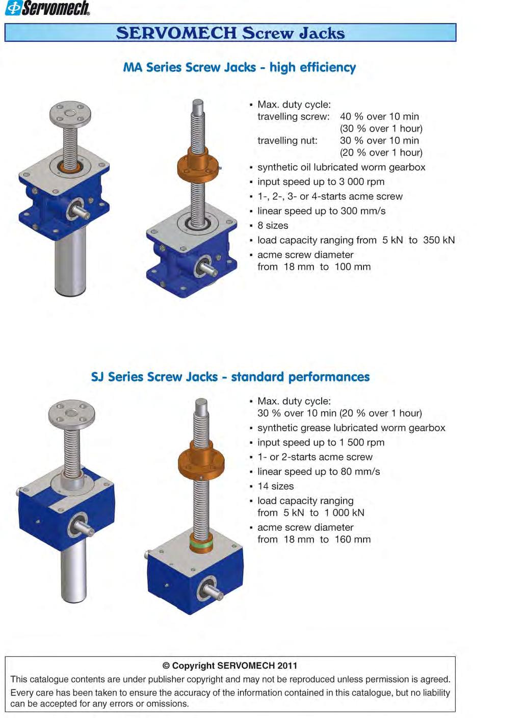
4 Screw jacks 1 Screw jacks verview Screw jacks transfrm a rtary mtin frm an electric, hydraulic r pneumatic mtr r even manual peratin int a linear mvement in a vertical (push-pull lifting) r hrizntal psitin. Screw jacks can be installed as a single unit r in lifting systems with different layuts cnnected by driveshafts, cuplings and bevel gearbxes. Screw jacks enable the synchrnized cnstant mvement f lifting systems even with a varying lad. SERVOMECH screw jacks are able t wrk under either push r pull lad cnditins and munted vertically upward, dwnward r hrizntally. SERVOMECH screw jacks mdels are available in tw mdels: travelling screw (Mdel A) travelling nut (Mdel B) SERVOMECH prduces tw screw jacks series: MA and SJ. Bth series are available in different sizes in rder t btain the mst suitable size in terms f perfrmances and csts fr each applicatin. MA Series: high perfrmances, acme screw, il lubricated, high efficiency, increased duty cycle up t 40% ver a 10 minute perid r 30% ver a 1 hur perid at 5 C envirnment temperature. SJ Series: standard perfrmances, acme screw, grease lubricated, increased duty cycle up t 30% ver a 10 minute perid r 0% ver a 1 hur perid at 5 C envirnment temperature MA BS Series: travelling ball screw (Md.A) r ball screw with travelling nut (Md.B), il lubricated, high perfrmances and efficiency, increased duty cycle up t 100% at 5 C envirnment temperature. SJ BS Series: ball screw with travelling nut (Md.B), grease lubricated, increased duty cycle up t 70% at 5 C envirnment temperature. Manufacturing features SERVOMECH screw jacks are ttally designed and manufactured inside the cmpany with high technlgy and CNC machinery. Quality System accrding t ISO 9001:008, certified by TÜV. Cntrl tests are carried ut in-line during manufacturing prcesses t mnitr the prductin quality. Final cntrl and functinal check test are carried ut t ensure the ttal quality and reliability f the final prduct. Input drive: wrm gear, high efficiency design, ZI invlute prfile, reduced axial backlash; brnze helical wrmwheel EN 198 CuSn1-C; true invlute wrm in steel 0 MnCr 5 (UNI EN 10084), with hardened and grund thread and shaft. Husing: mnblc husing designed fr a mre cmpact and rbust shape, able t carry heavy lads and ensure a high precisin level f machining. High resistance materials are used: casting in lluminium ally EN AC-AlSi10Mg T6 casting in cast irn EN-GJL-50 (UNI EN 1561) casting in spheridal graphite irn EN-GJS (UNI EN 1563) casting in steel Fe G 60 (UNI 4010)
5 Screw jacks Materials and cmpnents Acme screws, prfile accrding t ISO ISO 904 material: steel C 43 (UNI 7847) subjected t straightening prcess t ensure the regular alignment in peratin max. pitch errr ± 0.05 mm ver 300 mm thread length Threaded bars available n stck: ROLLED 1 start Tr 18 4 Tr 5 Tr 30 6 Tr 40 7 Tr 55 9 Tr 60 1 Tr 70 1 Tr 80 1 starts Tr 18 8 (P4) Tr 10 (P5) Tr 30 1 (P6) Tr (P7) 1 1 start starts WHIRLED Tr 30 6 Tr 40 7 Tr 55 9 Tr 60 1 Tr 70 1 Tr 80 1 Tr 90 1 Tr Tr Tr Tr Tr Tr 30 1 (P6) Tr (P7) Tr (P9) Tr 60 4 (P1) Tr 70 4 (P1) Tr 80 4 (P1) Tr 90 4 (P1) Tr (P1) Tr (P16) Tr 10 8 (P14) Tr (P14) Tr (P16) 3 starts Tr (P6) Tr 40 1 (P7) Tr 55 7 (P9) Tr (P1) Tr (P1) Tr (P16) 4 starts Tr 30 4 (P6) Tr 40 8 (P7) Tr (P9) Tr (P1) Tr (P1) Tr (P16) Brnze travelling nut, prfile accrding t ISO ISO 904 material: brnze nut with 1-start thread brnze EN CuAl9-C brnze nut with multiple starts thread brnze EN CuSn1-C max. axial backlash with new travelling nut: ( ) mm Ball screws material: steel 4 CrM 4 r 50 CrM 4 (UNI EN 10083) Threaded bars available n stck: ROLLED, accuracy grade IT 7 BS 14 5 BS 16 5 BS 0 5 BS 5 5 BS 3 5 BS BS BS 5 6 BS 3 10 BS 40 0 WHIRLED, accuracy grade IT 3 - IT 5 BS 5 10 BS 3 0 BS BS 0 5 BS 5 6 BS 3 10 BS BS BS BS BS BS 0 0 BS 5 10 BS 3 0 BS 40 0 BS 50 0 BS 63 0 BS 3 3 BS Ball nuts with flange DIN r with cylindrical flange material: steel 18 NiCrM 5 (UNI EN 10084) Ball nuts with ZERO backlash r preladed Threaded shafts with machined ends and nuts at custmer s drawing available n request. 3
6 Screw jacks Acme screw jacks 1 MA Series SERVOMECH acme screw jacks SJ Series travelling screw (Mdel A) travelling nut (Mdel B) travelling screw (Mdel A) travelling nut (Mdel B) MA 5 Tr 18 4 SJ 5 Tr 18 4 MA 10 Tr 5 SJ 10 Tr 5 MA 5 Tr 30 6 SJ 5 Tr 30 6 MA 50 Tr 40 7 SJ 50 Tr 40 7 MA 80 Tr 55 9 SJ 100 Tr 55 9 MA 100 Tr 60 1 SJ 150 Tr 60 1 MA 00 Tr 70 1 SJ 00 Tr 70 1 MA 350 Tr SJ 50 Tr 80 1 SJ 300 Tr 90 1 SJ 350 Tr SJ 400 Tr SJ 600 Tr SJ 800 Tr SJ 1000 Tr MA Series: SJ Series: high efficiency screw jacks standard perfrmances screw jacks 8 standard sizes 14 standard sizes with lad capacity frm 5 kn t 350 kn with lad capacity frm 5 kn t kn Mdel A: travelling screw Mdel B: travelling nut 1- start acme screw 1- start acme screw frm Tr 18 4 t Tr frm Tr 18 4 t Tr starts acme screw -starts acme screw frm Tr 18 8 (P4) t Tr (P16) frm Tr 18 8 (P4) t Tr (P16) Screw jacks MA Series Mdel A with travelling screw: 3- r 4-starts acme screws available 6 different input versins fr each size and rati Vers.1: single input shaft Vers.: duble free input shaft Vers.3: flange and hllw shaft input fr IEC mtr Vers.4: flange and hllw shaft input fr IEC mtr with secnd free input shaft Vers.5: Vers.1 + bell husing and cupling fr IEC mtr Vers.6: Vers. + bell husing and cupling fr IEC mtr lng-life synthetic il lubricated wrm gear lng-life synthetic grease lubricated wrm gear peratin with lw nise level max. input speed allwed with input speed up t rpm rpm suitable fr high linear speed cmpetitive in industrial applicatins and high duty cycle applicatins price/perfrmance : excellent rati wide range f accessries available 4
7 Screw jacks Ball screw jacks SERVOMECH ball screw jacks MA BS Series SJ BS Series travelling ball screw (Mdel A) travelling ball nut (Mdel B) travelling ball nut (Mdel B) 1 MA 5 BS 14 5 BS 0 5 BS 0 5 MA 5 SJ 5 BS 16 5 BS 5 6 BS 5 6 MA 10 BS 16 5 BS 5 6 BS 5 6 MA 10 SJ 10 BS 0 5 BS 3 5 BS 3 5 MA 5 BS 3 10; BS 3 0; BS 3 5; BS 3 10; BS 3 5; MA 5 SJ 5 BS 3 3 BS 3 0; BS 3 3 BS 3 10; BS 3 0 MA 50 BS 40 10; BS 40 0; BS 40 10; BS 40 0; MA 50 BS BS SJ 50 BS 40 10; BS 40 0 MA 80 BS 50 10; BS 50 0 SJ 100 BS 50 10; BS 50 0 MA 100 BS 50 10; BS 50 0; BS 63 10; BS 63 0 MA 100 BS 63 10; BS 63 0 SJ 150 BS 63 10; BS 63 0 MA 00 BS MA 00 BS BS SJ 00 BS MA 350 BS MA 350 BS SJ 50 BS MA BS Series: high efficiency screw jacks, suitable fr cntinuus peratin als, duty cycle up t 100 %, input speed up t rpm 8 standard sizes with lad capacity frm 5 kn t 350 kn Mdel A: travelling ball screw Mdel B: travelling ball nut ball screw frm BS 14 5 t BS SJ BS Series: standard perfrmances screw jacks, Mdel B (travelling nut) available nly, duty cycle up t 70 %, input speed up t rpm 8 standard sizes with lad capacity frm 5 kn t 50 kn Mdel B: travelling ball nut ball screw frm BS 0 5 t BS different input versins fr each size and rati Vers.1: single input shaft Vers.: duble free input shaft Vers.3: flange and hllw shaft input fr IEC mtr Vers.4: flange and hllw shaft input fr IEC mtr with secnd free input shaft Vers.5: Vers.1 + bell husing and cupling fr IEC mtr Vers.6: Vers. + bell husing and cupling fr IEC mtr lng-life synthetic il lubricated wrm gear lng-life synthetic grease lubricated wrm gear wide range f accessries available NOTE: Perfrmances, features and dimensins f ball screw jacks and ball screws are quted in the specific catalgues: catalgue Ball screw jacks, catalgue Ball screws and nuts. 5
8 Screw jacks 1 Mdels Bth MA and SJ Series screw jacks are available in tw mdels: with travelling screw (Mdel A) with travelling nut (Mdel B) The chice f the mdel depends n the cnfiguratin and requirements f the applicatin. The perfrmances are in general the same fr bth mdels. SERVOMECH screw jacks can be perated in vertical r hrizntal planes, r angles in-between. Input ptins available: free shaft, duble free shaft, mtr flange with r withut secnd shaft. travelling ball screw (Mdel A) travelling ball nut (Mdel B) The brnze nut is integral with the wrm wheel. The linear mtin is given by the acme screw being driven thrugh the centre f the wrm wheel. In peratin, the screw des nt rtate. Space must be available n bth screw jacks sides fr the screw t prtrude belw the gear husing. The acme screw is fixed t the wrm wheel. In peratin the screw rtates with the wrm wheel at the same speed, driving the brnze nut up and dwn. The linear mtin f the nut is pssible nly if the reacting trque is applied, aviding the integral rtatin with the acme screw. Optins: prtective tube prtective bellws safety brnze nut varius screw end fixings strke end switches anti-turn device wear indicatr switch adjustable backlash stp nut trunnin munting stainless steel acme screw brnze guides Optins: prtective bellws safety brnze nut wear indicatr switch adjustable backlash stainless steel acme screw trunnin munting travelling nut travelling nut at custmer s drawing 6
9 Screw jacks Versins INPUT SHAFT ROTATION SCREW OR NUT LIFTING DIRECTION 1 Mdel A Mdel B INPUT VERSIONS Vers.1 Vers. Vers.3 Vers.4 Vers.5 Vers.6 Vers.1: single input shaft Vers.: duble free input shaft Vers.3: flange and hllw shaft input fr IEC mtr Vers.4: flange and hllw shaft input fr IEC mtr with secnd free input shaft Vers.5: Vers.1 + bell husing and cupling fr IEC mtr Vers.6: Vers. + bell husing and cupling fr IEC mtr SCREW JACK MOUNTING POSITIONS UPWARD (U) DOWNWARD (D) HORIZONTAL (H) RIGHT-HAND (RH) LEFT-HAND (LH) RIGHT-HAND (RH) LEFT-HAND (LH) RIGHT-HAND (RH) LEFT-HAND (LH) 7
10 Screw jacks 1 Screw jacks selectin criteria Screw jacks transfrm a rtary mvement int a linear mvement. Due t the screw-nut efficiency, this transfrmatin implies a lss f energy depending n the screw and the nut type which is in inverse relatin t their efficiency. Therefre, the energy lss is higher with 1-start acme screw and nut when cmpared with - r mre starts acme screw and nut. Therefre t select the right screw jack suitable fr an applicatin, it is necessary t cnsider the duty cycle required by the applicatin F u [%] and cmpare it t the duty cycle that the screw jack can perfrm F i [%]. The applicatin duty cycle F u [%] required is the rati between the wrking time under lad required by the applicatin during a reference time perid and the reference time perid itself, expressed in percentage. Wrking time during reference time perid T F [%] = Reference time perid T [min] T rif - reference time perid, expressed in minutes: T ref = 10 minutes fr shrt, but frequent wrking cycles T ref = 1 hur (60 min) fr lng, but infrequent wrking cycles The screw jack duty cycle F i [%] allwed is the percentage f time referred t the reference time perid T ref during which the screw jack can perate under maximum lad cnditins - stated in this catalgue - at 5 C envirnment temperature, t avid the risk f internal parts verheating. Therefre, the main limit t the wrking time f screw jacks is ften due t the thermal pwer limits and nt t the maximum permissible perating mechanical pwer. The screw jack duty cycle F i [%] is related t the maximum permissible pwer. If the pwer required by the applicatin is lwer than the maximum permissible pwer, than the screw jack can be used with a higher duty cycle. [min] rif u rif 100 / max MA Series SJ Series - Pwer required by the applicatin max - Screw jack s max permissible pwer (see perfrmances tables) Screw jack duty cycle [%] ver 10 min If the envirnment temperature is higher than 5 C, the screw jack duty cycle F i [%] has t be reduced by applying a crrectin factr f T as per the fllwing frmula: where: 80 T [ C] f T = 55 T [ C] - envirnment temperature, expressed in degree Celsius If the envirnment temperature increases, the permissible duty cycle f the screw jack F i [%] is reduced. 8
11 Screw jacks In rder t make a crrect screw jack selectin, we recmmend the fllwing selectin prcedure: 1. Mdel: - Mdel A travelling screw - Mdel B travelling nut. SERVOMECH screw jack series: - MA Series: high efficiency screw jack with acme screw, il lubricated - SJ Series: standard perfrmances screw jack with acme screw, grease lubricated 3. Screw jack size: - Pull r push lad - Strke - Linear speed - Pwer required 4. Input versin: - Vers.1: single free input shaft - Vers.: duble free input shaft - Vers.3: flange and hllw shaft input fr IEC mtr - Vers.4: flange and hllw shaft input fr IEC mtr with secnd free input shaft - Vers.5: Vers.1 + bell husing and cupling fr IEC mtr - Vers.6: Vers. + bell husing and cupling fr IEC mtr 5. Screw jack munting psitin: - Upward U - Dwnward D - Hrizntal H - Right-hand RH - Left-hand LH 6. Accessries required 1 Screw jack selectin The screw jack selectin is the last step f a mre cmplex glbal lifting-system selectin prcedure, where the verall dimensins and safety requirements f the applicatin have t be cnsidered as an integral part f that selectin. In this sectin we nly fcus n a single screw jack selectin. Yu will find mre exhaustive cmments and recmmendatins n the screw jacks cmplete lifting system chapter. 1. Screw jack mdel selectin: all SERVOMECH screw jacks versins and sizes are available in tw different mdels: - Mdel A travelling screw - Mdel B travelling nut The chice between the tw different mdels nly depends n the cnfiguratin and munting details f the applicatin. In case f Mdel B (rtating screw and external translating nut) selectin, we recmmend t pay attentin t the fllwing: - screw and nut lubricatin - acme screw prtectin - nly axial lad can be applied n the translating nut referred t the rtating acme screw axis - rtating screw end, especially in case f lng strke length and push lad - ff-set r radial lad applied n the nut may lead t dangerus misalignment between screw and nut, s it is nt permitted. If present, it must be supprted by an apprpriate, suitable slutin. 9
12 Screw jacks 1. SERVOMECH screw jacks series: The screw jack s duty cycle and the duty cycle required by the applicatin F u [%] are the mst imprtant factrs in chsing between the tw available screw jacks series, as previusly described. The duty cycle required by the applicatin F u [%] has t be lwer than r equal t the wrking duty cycle rating the screw jack can perfrm F i [%], inclusive the envirnment temperature crrectin factr (f T ): F u [%] F i [%] Here belw are values f the max. duty cycle F i [%] at 5 C envirnment temperature fr the SERVOMECH screw jacks series: Duty cycle allwed F i [%] MA Series SJ Series F i [%] ver 10 min time perid 40 % 30 % F i [%] ver 1 hur time perid 30 % 0 % Lifting Systems Usually, a screw jack lifting system is cmpsed f several lifting pints (see examples n pages 94-95). Screw jack s psitin and number depend n applicatin requirements as: - dimensin and surface f the platfrm r plane - required strke length - ttal lifting lad (dynamic lad) - lifting system cnfiguratin, guided r nt guided lad Furthermre, specific applicatin prject requirements may als influence the selectin. A new lifting system prject can be very cmplex and therefre it requires the clever evaluatin f many different technical and applicatin details, in rder t prvide a functinal, safe and cmpetitive slutin. Here are sme suggestins that can help the lifting system s designer n his prject evaluatins. Static safety: Firstly, the required r desired safety level has t be cnsidered. On screw jack prduct, there are n regulatins n the matter f safety standards and technical data declared n catalgue. Many manufacturers d nt use the same safety factrs n their technical calculatins and als the materials may be different. We recmmend a full evaluatin f all screw jack cmpnents. Dimensins, uter diameter and lead f screw thread are nt enugh fr a cmplete evaluatin. It is als imprtant t evaluate the wrm gear in terms f: - centre distance, verall dimensins and ttal weight - axial bearings: type and size - nut: material and dimensins Nrms and rules: In case, be sure t cnsider all nrms and rules which the prject must cmply with. This can significantly affect the final slutin. Nise and vibratins: Fr applicatins which require a lw and cntrlled nise level, we recmmend a slutin which allws, with same final perfrmances, a lwer input speed fr the cnnecting shaft. This will help t reduce r eliminate als vibratins r dangerus input speeds fr the cnnecting shafts. 10
13 Screw jacks Example: lifting stages fr theatres, lecture r cncert hall: - mtr speed reduced t max. ( ) rpm - use f bevel gearbxes with rati 1 : 1 - balanced cnnecting shafts, well aligned and supprted, max. nn-supprted length (... 3) m - SERVOMECH screw jacks with rati RV (high linear speed) and multiplied starts acme screw Hanging lad: Auxiliary safety nuts are available t cmply with nrms and rules abut hanged lads with presence f persnnel fr maintenance. Self-lcking: Generally, the statically self-lcking cnditin f the lifting system can be achieved by using a 1-start acme screw jack. Smetimes, t cmply with sme nrms and rules, a certain mechanical selflcking cnditin can nly be achieved by a lwer than 4 helix angle acme screw with a lead smaller than the standard. Thse special executins are available n request. 1 Psitining (stpping) accuracy: The psitining (stpping) accuracy can be achieved by using brakemtrs r frequency inverters t cntrl speed and acceleratin and deceleratin ramps, especially in case f dwnward mving lads. Operating safety: Different safety devices can als be cnsidered r requested fr the applicatin: - mechanical safety: safety nut, mechanical stp f the lad; - electric r electrnic safety: wear cntrl f the wrking nut t check the distance between wrking and safety nut; speed cntrl f the cnnecting shaft; rtatin detectin f the wrm wheel; cntrl f max. pwer r current required fr the lifting system. Lad inertia: If the lad has t be rapidly accelerated r decelerated, in applicatins with high linear speed, we recmmend t use an apprpriate drive t cntrl the acceleratin and deceleratin ramps (fr example, frequency inverter fr AC 3-phase mtrs r duble plarity mtrs and sft-start devices). Guided lad: In case f applicatins with large dimensins, high lads and lng strkes, we recmmend t evaluate the pssibility t guide the lad. If the lad is guided, a smaller screw diameter may be selected and cnsequently a cheaper screw jacks can be used, whilst maintaining the same functinality and static lad capability. This means a cst effective final slutin fr the prject. Screw jacks with increased acme screw diameter, if the static resistance is mre significant than the dynamic applicatin cnditins fr lifting systems: - lng strke with medium static push lad - medium strkes with high static push lad SERVOMECH screw jacks with increased diameter acme screw are available t ffer a mre cst effective slutin. Fr assistance in selecting lifting systems and linear mtin devices, SERVOMECH Engineering Dpt. is available t supprt yu free f charge. 11
14 Screw jacks Self-lcking 1 An acme screw jack is in self-lcking cnditin when: a push r pull lad applied n a nt wrking screw jack des nt start the linear mvement (static self-lcking cnditin); by interrupting the mtr pwer supply f a wrking screw jack with push r pull lad, the mvement stps (dynamic self-lcking cnditin). Self-lcking and back-driving cnditins are defined in the fllwing 4 situatins: 1) Static self-lcking: nt running screw jack withut lad vibratins; the applicatin f a push r pull frce (until the maximum allwed) des nt cause the linear mvement f the acme screw (Mdel A) r f the travelling brnze nut (Mdel B). This cnditin happens when the direct efficiency value 1) is lwer than ) Dynamic self-lcking: Wrking screw jack with a lad ppsite the mtin: by interrupting the mtr pwer supply the screw jack stps. This cnditin happens when the direct efficiency value 1) is lwer than 0.5. Wrking screw jack with a lad applied n the same directin f the mtin: the screw jack s stp is nt guaranteed by interrupting the mtr pwer supply. The screw jack stps nly if the direct efficiency value 1) is lwer than 0.0 and, anyway, it stps in an unrepeatable psitin. In this case, we recmmend t use a brake mtr t stp the lad and keep it in psitin, aviding the mtin start in case f pushes r vibratins. 3) Uncertain self-lcking: with direct efficiency values 1) between 0.30 and 0.50, the screw jacks are in an uncertain self-lcking cnditin. The self-lcking depends n the lad and the inertia f the system. In this case we recmmend t use a brake mtr t guarantee the self-lcking cnditin r t cntact SERVOMECH Engineering Dpt. t evaluate the applicatin. 4) Back-driving: screw jacks with direct efficiency value 1) higher than 0.50 are never self-lcking. We remind yu that, in any case, als t start a nt self-lcking screw jack a certain minimum lad must be applied. T define this lad value please cntact SERVOMECH Engineering Dpt. SELF-LOCKING UNCERTAIN SELF-LOCKING BACK-DRIVING ) The direct efficiency values are shwn in the relative tables (see pages 36, 61 and 67). 1
15 Screw jacks Acme screw buckling One f the mst imprtant screw jack selectin criteria is the buckling resistance f the acme screw. Buckling limits are relevant fr push lad nly. SERVOMECH cnsiders three cases: Euler I: screw jack husing firmly fixed t the base free travelling acme screw end screw jack husing firmly fixed t the base free travelling nut Euler II: screw jack husing and travelling acme screw end fixed t pivting supprts screw jack husing and travelling nut fixed t pivting supprts Euler III: screw jack husing firmly fixed t the base guided travelling acme screw end screw jack husing firmly fixed t the base guided travelling nut Fllwing diagrams (knwn as Euler curves) shw the max. push lad admitted n the acme screw, cnsidering a safety factr against buckling equal t 4. Fr mre accurate evaluatin in case f particular applicatin requirements, critical fr safety reasns (e.g. theatre lifts), cntact SERVOMECH Engineering Dpt. Euler I: screw jack husing firmly fixed t the base - free travelling acme screw end screw jack husing firmly fixed t the base - free travelling nut Example: T suit a push lad f 60 kn applied n an acme screw mm lng, the right screw size is Tr 70 1 munted n a screw jack MA 00 r SJ 00. Lad [kn] Tr Tr Tr Tr 18 4 Tr 5 Tr 30 6 Tr 40 7 Tr 55 9 Tr 60 1 Tr Tr Tr 90 1 Tr 80 1 Tr 70 1 Euler I Safety factr: Acme screw length, L [m] 13
16 Screw jacks Acme screw buckling 1 Euler II: screw jack husing and travelling acme screw end fixed t pivting supprts screw jack husing and travelling nut fixed t pivting supprts Example: T suit a push lad f 0 kn applied n an acme screw mm lng, the right screw size is Tr 40 7 munted n a screw jack MA 50 r SJ 50. Lad [kn] Tr Tr Tr Tr Tr Tr 90 1 Tr Tr 18 4 Tr 5 Tr 30 6 Tr 40 7 Tr 70 1 Tr 60 1 Tr 55 9 Euler II Safety factr: Acme screw length, L [m] 14
17 Screw jacks Acme screw buckling Euler III: screw jack husing firmly fixed t the base - guided travelling acme screw end screw jack husing firmly fixed t the base - guided travelling nut Example: T suit a push lad f 100 kn applied n an acme screw mm lng, the right screw size is Tr 80 1 munted n a screw jack SJ Lad [kn] Tr Tr Tr Tr Tr Tr 90 1 Tr Tr Tr 18 4 Tr 5 Tr 30 6 Tr 60 1 Tr 55 9 Euler III Safety factr: Acme screw length, L [m] Tr
18 1 Screw jacks Critical rtating speed f acme screw Fr travelling nut (Mdel B) screw jacks, the acme screw rtating speed must nt reach the first critical speed f the screw itself, which depends n the thread diameter and lead, screw length and type f the screw end supprt. Free acme screw end Example: Fr a screw jack SJ 150 with acme screw Tr 60 1 (1-start r mre) m lng with free end, the max. allwed rtating speed is 40 rpm. With a 1-start thread, this rtating speed is equivalent t a linear speed f 85 mm/s. n max = d L min d min [mm] - min. thread diameter (fr a thread Tr d P: d min = d - P) L [mm] - acme screw length Acme screw rtating speed [g/min] Acme screw length, L [m] 1 - Tr Tr Tr Tr Tr Tr Tr Tr Tr Tr Tr Tr Tr Tr
19 Screw jacks ATTENTION! In case f hrizntal munting, an acme screw static deflectin, caused by its weight and pssibly aggravated by the presence f the push lad, shuld always be cnsidered. Therefre, we recmmend an accurate evaluatin and use f a screw supprting system n tw nut sides, integral and travelling with the nut itself; this will ensure the crrect alignment and cncentricity between the screw and the nut. In case f dubts, please cntact SERVOMECH Engineering Dpt. Supprted acme screw end Example: Fr a screw jack MA 50 with acme screw Tr 40 7 (1-start r mre) 3 m lng with supprted end, max. allwed rtating speed is 550 rpm. With a 1-start thread, this rtating speed is equivalent t a linear speed f 64 mm/s. 1 n max = d L min d min [mm] - min. thread diameter (fr a thread Tr d P: d min = d - P) L [mm] - acme screw length Acme screw rtating speed [g/min] Acme screw length, L [m] 1 - Tr Tr Tr Tr Tr Tr Tr Tr Tr Tr Tr Tr Tr Tr
 STRUCTURAL ELEMENTS 1 10 11 8 7 6 1 3 13 4 9 14 8 11 10 5 6 7 1 - acme screw in steel C 43 (UNI 7847), whirled thread - wrm shaft with true invlute, grund wrm prfile ZI (UNI 4760), made in steel,")
20 Screw jacks MA Series Screw jacks MA Series with travelling screw (Md.A) STRUCTURAL ELEMENTS acme screw in steel C 43 (UNI 7847), whirled thread - wrm shaft with true invlute, grund wrm prfile ZI (UNI 4760), made in steel, case-hardened 3 - brnze wrmwheel with true invlute prfile ZI (UNI 4760), the length f the internal nut is duble respect t SJ Series; the bigger mass f the brnze nut allws a higher duty cycle and a lnger life 4 - thrust ball bearing fr high lad capacity 5 - gear bx shape which allws effective heat dissipatin giving increased duty cycle 6 - radial guide f the wrmwheel fr increased stiffness and imprved efficiency 7 - raised cver with brnze guide against radial lad fr acme screw; the raised cver may als be used as a spigt diameter 8 - grub screw which prevents the threaded cver unscrewing 9 - synthetic il lubricated wrm gearbx fr a better heat dissipatin; this allws higher input speed, imprved efficiency and lnger life 10 - radial lubricant seal 11 - O-Ring as lubricant seal 1 - breather 13 - il level plug 14 - il drain plug 18
 STRUCTURAL ELEMENTS 1 16 17 14 5 4 11 13 18 3 19 15 9 6 14 0 17 16 8 7 1 1 - acme screw in steel C 43 (UNI 7847), whirled thread - brnze travelling nut with flange 3 - wrm shaft with true invlute,")
21 Screw jacks MA Series Screw jacks MA Series with travelling nut (Md.B) STRUCTURAL ELEMENTS acme screw in steel C 43 (UNI 7847), whirled thread - brnze travelling nut with flange 3 - wrm shaft with true invlute, grund wrm prfile ZI (UNI 4760), made in steel, case-hardened 4 - brnze wrmwheel with true invlute prfile ZI (UNI 4760) 5 - cast irn supprt f the wrmwheel brnze rim 6 - acme screw fixed t the wrmwheel thrugh the cylindrical centring part and LEFT-HAND (fr push lad) r RIGHT-HAND (fr pull lad) metric thread 7 - lck nut with the ppsite directin metric thread t ensure safe acme screw fixing 8 - acme screw wrmwheel pins against unscrewing 9 - thrust ball bearing fr high lad capacity 10 - gear bx 11 - lw cver 1 - raised cver; may als be used as a spigt diameter 13 - radial brnze guide f the wrmwheel, fr increased stiffness and imprved efficiency 14 - grub screw which prevents the threaded cver unscrewing 15 - synthetic il lubricated wrm gearbx 16 - radial lubricant seal 17 - O-Ring as lubricant seal 18 - breather 19 - il level plug 0 - il drain plug
22 Screw jacks MA Series Screw jacks MA Series with 1-start acme screw TECHNICAL SPECIFICATIONS SCREW JACK SIZE MA 5 MA 10 MA 5 MA 50 Lad capacity [kn], (push - pull) start acme screw Tr 18 4 Tr 5 Tr 30 6 Tr 40 7 Wrm gear centre distance [mm] RV 1 : 4 (4 : 16) 1 : 5 (4 : 0) 1 : 6 (4 : 4) 1 : 7 (4 : 8) Available rati RN 1 : 16 ( : 3) 1 : 0 1 : 18 ( : 36) 1 : 14 ( : 8) RL 1 : 4 1 : 5 1 : 4 1 : 8 RV Strke [mm] fr 1 input shaft revlutin Starting efficiency Rati Rati RN RL RV RN RL RV Running efficiency at 3000 rpm ( 1 ) Rati RN RL RV Starting trque n input shaft at max. lad [] Rati RN RL Max. permissible perating pwer ( ) [] Rati RV RN RL Reactive trque n acme screw (nut) required at max. lad [] Gear bx material casting in aluminium ally EN AC-AlSi10Mg T6 casting in spheridal graphite irn EN-GJS (UNI EN 1563) Mass f screw jack withut acme screw [kg] Mass fr every 100 mm f acme screw [kg] ( 1 ) - efficiency figures at different input speed n page 36 ( ) - THERMAL limit, referred t fllwing wrking cnditins duty cycle 40 % ver 10 min time perid (30 % ver 1 hur time perid) fr screw jacks with travelling screw (Md.A) duty cycle 30 % ver 10 min time perid (0 % ver 1 hur time perid) fr screw jacks with travelling nut (Md.B) at 5 C envirnment temperature 0
23 Screw jacks MA Series MA 80 MA 100 MA 00 MA 350 SCREW JACK SIZE Lad capacity [kn], (push - pull) Tr 55 9 Tr 60 1 Tr 70 1 Tr start acme screw Wrm gear centre distance [mm] 1 : 7 (4 : 8) 1 : 8 (4 : 3) 1 : 8 (4 : 3) 3 : 3 RV Screw jacks MA Series with 1-start acme screw TECHNICAL SPECIFICATIONS 1 : 14 ( : 8) 1 : 4 1 : 4 1 : 16 ( : 3) RN Available rati 1 : 8 1 : 3 1 : 3 1 : 3 RL RV RN RL RV RN1 Rati Rati Strke [mm] fr 1 input shaft revlutin Starting efficiency RL RV RN RL1 Rati Running efficiency at 3000 rpm ( 1 ) RV RN RL1 Rati Starting trque n input shaft at max. lad [] RV RN RL1 Rati Max. permissible perating pwer ( ) [] casting in spheridal graphite irn EN-GJS (UNI EN 1563) Reactive trque n acme screw (nut) required at max. lad [] Gear bx material Mass f screw jack withut acme screw [kg] Mass fr every 100 mm f acme screw [kg] ( 1 ) - efficiency figures at different input speed n page 36 ( ) - THERMAL limit, referred t fllwing wrking cnditins duty cycle 40 % ver 10 min time perid (30 % ver 1 hur time perid) fr screw jacks with travelling screw (Md.A) duty cycle 30 % ver 10 min time perid (0 % ver 1 hur time perid) fr screw jacks with travelling nut (Md.B) at 5 C envirnment temperature 1
24 Screw jacks MA Series - 1-start acme screw Fllwing tables shw the screw jack and relative TORQUE [] and POWER [] n input shaft, with reference t the INPUT SPEED, the RATIO (RV, RN, RL) and the [kn] applied n the screw jack. Intermediate values fr linear speed v, trque and pwer at different input speed can be calculated by linear interplatin f the figures stated in the table. The figures in the tables refer t wrk at 5 C envirnment temperature and max. duty cycle f: 40 % ver 10 min time perid r 30 % ver 1 hur time perid, fr screw jacks with travelling screw (Md.A), 30 % ver 10 min time perid r 0 % ver 1 hur time perid, fr screw jacks with travelling nut (Md.B) ATTENTION! The figures in the red shaded area indicate peratinal restrictins due t thermal limits. When the selectin is made within such area, the duty cycle must be reduced r the greater size screw jack must be selected, in rder t allw effective heat dissipatin. Fr a better evaluatin, please cntact SERVOMECH Engineering Dpt. MA 5 5 kn 4 kn 3 kn 1 kn RV1 RN1 RL1 MA kn 8 kn 6 kn kn RV1 RN1 RL1 RV1 RN1 RL1 RV1 RN1 RL1 RV1 RN1 RL1 RV1 RN1 RL MA kn 35 kn 5 kn 10 kn RV1 RN1 RL1 RV1 RN1 RL1 RV1 RN1 RL1 RV1 RN1 RL1 RV1 RN1 RL1 RV1 RN1 RL1 RV1 RN1 RL1 RV1 RN1 RL1 RV1 RN1 RL MA 5 5 kn 0 kn 15 kn 10 kn RV1 RN1 RL RV1 RN1 RL1 RV1 RN1 RL1 RV1 RN1 RL1 RV1 RN1 RL
25 Screw jacks MA Series - 1-start acme screw Fllwing tables shw the screw jack and relative TORQUE [] and POWER [] n input shaft, with reference t the INPUT SPEED, the RATIO (RV, RN, RL) and the [kn] applied n the screw jack. Intermediate values fr linear speed v, trque and pwer at different input speed can be calculated by linear interplatin f the figures stated in the table. The figures in the tables refer t wrk at 5 C envirnment temperature and max. duty cycle f: 40 % ver 10 min time perid r 30 % ver 1 hur time perid, fr screw jacks with travelling screw (Md.A), 30 % ver 10 min time perid r 0 % ver 1 hur time perid, fr screw jacks with travelling nut (Md.B) ATTENTION! The figures in the red shaded area indicate peratinal restrictins due t thermal limits. When the selectin is made within such area, the duty cycle must be reduced r the greater size screw jack must be selected, in rder t allw effective heat dissipatin. Fr a better evaluatin, please cntact SERVOMECH Engineering Dpt. MA kn 60 kn 40 kn 0 kn RV1 RN1 RL1 RV1 RN1 RL1 RV1 RN1 RL1 RV1 RN1 RL1 RV1 RN1 RL MA kn 80 kn 50 kn 0 kn RV1 RN1 RL1 RV1 RN1 RL1 RV1 RN1 RL1 RV1 RN1 RL1 RV1 RN1 RL MA kn 150 kn 100 kn 50 kn RV1 RN1 RL1 RV1 RN1 RL1 RV1 RN1 RL1 RV1 RN1 RL1 RV1 RN1 RL MA kn 50 kn 150 kn 100 kn RV1 RN1 RL1 RV1 RN1 RL1 RV1 RN1 RL1 RV1 RN1 RL1 RV1 RN1 RL
26 Screw jacks MA Series Screw jacks MA Series with -starts acme screw TECHNICAL SPECIFICATIONS SCREW JACK SIZE MA 5 MA 10 MA 5 MA 50 Lad capacity [kn], (push - pull) starts acme screw Tr 18 8 (P4) Tr 10 (P5) Tr 30 1 (P6) Tr (P7) Wrm gear centre distance [mm] RV 1 : 4 (4 : 16) 1 : 5 (4 : 0) 1 : 6 (4 : 4) 1 : 7 (4 : 8) Available rati RN 1 : 16 ( : 3) 1 : 0 1 : 18 ( : 36) 1 : 14 ( : 8) RL 1 : 4 1 : 5 1 : 4 1 : 8 RV1 Strke [mm] fr 1 input shaft revlutin Starting efficiency Rati Rati RN RL RV RN RL RV Running efficiency at 3000 rpm ( 1 ) Rati RN RL RV Starting trque n input shaft at max. lad [] Rati RN RL Max. permissible perating pwer ( ) [] Rati RV RN RL Reactive trque n acme screw (nut) required at max. lad [] Gear bx material casting in aluminium ally EN AC-AlSi10Mg T6 casting in spheridal graphite irn EN-GJS (UNI EN 1563) Mass f screw jack withut acme screw [kg] Mass fr every 100 mm f acme screw [kg] ( 1 ) - efficiency figures at different input speed n page 36 ( ) - THERMAL limit, referred t fllwing wrking cnditins duty cycle 40 % ver 10 min time perid (30 % ver 1 hur time perid) fr screw jacks with travelling screw (Md.A) duty cycle 30 % ver 10 min time perid (0 % ver 1 hur time perid) fr screw jacks with travelling nut (Md.B) at 5 C envirnment temperature 4
27 Screw jacks MA Series MA 80 MA 100 MA 00 MA 350 SCREW JACK SIZE Lad capacity [kn], (push - pull) Tr (P9) Tr 60 4 (P1) Tr 70 4 (P1) Tr (P16) -starts acme screw Wrm gear centre distance [mm] 1 : 7 (4 : 8) 1 : 8 (4 : 3) 1 : 8 (4 : 3) 3 : 3 RV Screw jacks MA Series with -starts acme screw TECHNICAL SPECIFICATIONS 1 : 14 ( : 8) 1 : 4 1 : 4 1 : 16 ( : 3) RN Available rati 1 : 8 1 : 3 1 : 3 1 : 3 RL RV RN RL RV RN1 Rati Rati Strke [mm] fr 1 input shaft revlutin Starting efficiency RL RV RN RL1 Rati Running efficiency at 3000 rpm ( 1 ) RV RN RL1 Rati Starting trque n input shaft at max. lad [] RV RN RL1 Rati Max. permissible perating pwer ( ) [] casting in spheridal graphite irn EN-GJS (UNI EN 1563) Reactive trque n acme screw (nut) required at max. lad [] Gear bx material Mass f screw jack withut acme screw [kg] Mass fr every 100 mm f acme screw [kg] ( 1 ) - efficiency figures at different input speed n page 36 ( ) - THERMAL limit, referred t fllwing wrking cnditins duty cycle 40 % ver 10 min time perid (30 % ver 1 hur time perid) fr screw jacks with travelling screw (Md.A) duty cycle 30 % ver 10 min time perid (0 % ver 1 hur time perid) fr screw jacks with travelling nut (Md.B) at 5 C envirnment temperature 5
28 Screw jacks MA Series - -starts acme screw Fllwing tables shw the screw jack and relative TORQUE [] and POWER [] n input shaft, with reference t the INPUT SPEED, the RATIO (RV, RN, RL) and the [kn] applied n the screw jack. Intermediate values fr linear speed v, trque and pwer at different input speed can be calculated by linear interplatin f the figures stated in the table. The figures in the tables refer t wrk at 5 C envirnment temperature and max. duty cycle f: 40 % ver 10 min time perid r 30 % ver 1 hur time perid, fr screw jacks with travelling screw (Md.A), 30 % ver 10 min time perid r 0 % ver 1 hur time perid, fr screw jacks with travelling nut (Md.B) ATTENTION! The figures in the red shaded area indicate peratinal restrictins due t thermal limits. When the selectin is made within such area, the duty cycle must be reduced r the greater size screw jack must be selected, in rder t allw effective heat dissipatin. Fr a better evaluatin, please cntact SERVOMECH Engineering Dpt. MA 5 5 kn 4 kn 3 kn 1 kn RV RN RL MA kn 8 kn 6 kn kn RV RN RL RV RN RL RV RN RL RV RN RL RV RN RL MA kn 35 kn 5 kn 10 kn RV RN RL RV RN RL RV RN RL RV RN RL RV RN RL RV RN RL RV RN RL RV RN RL RV RN RL MA 5 5 kn 0 kn 15 kn 10 kn RV RN RL RV RN RL RV RN RL RV RN RL RV RN RL
29 Screw jacks MA Series - -starts acme screw Fllwing tables shw the screw jack and relative TORQUE [] and POWER [] n input shaft, with reference t the INPUT SPEED, the RATIO (RV, RN, RL) and the [kn] applied n the screw jack. Intermediate values fr linear speed v, trque and pwer at different input speed can be calculated by linear interplatin f the figures stated in the table. The figures in the tables refer t wrk at 5 C envirnment temperature and max. duty cycle f: 40 % ver 10 min time perid r 30 % ver 1 hur time perid, fr screw jacks with travelling screw (Md.A), 30 % ver 10 min time perid r 0 % ver 1 hur time perid, fr screw jacks with travelling nut (Md.B) ATTENTION! The figures in the red shaded area indicate peratinal restrictins due t thermal limits. When the selectin is made within such area, the duty cycle must be reduced r the greater size screw jack must be selected, in rder t allw effective heat dissipatin. Fr a better evaluatin, please cntact SERVOMECH Engineering Dpt. MA kn 60 kn 40 kn 0 kn RV RN RL RV RN RL RV RN RL RV RN RL RV RN RL MA kn 80 kn 50 kn 0 kn RV RN RL RV RN RL RV RN RL RV RN RL RV RN RL MA kn 150 kn 100 kn 50 kn RV RN RL RV RN RL RV RN RL RV RN RL RV RN RL MA kn 50 kn 150 kn 100 kn RV RN RL RV RN RL RV RN RL RV RN RL RV RN RL
30 Screw jacks MA Series Screw jacks MA Series with 3-starts acme screw TECHNICAL SPECIFICATIONS SCREW JACK SIZE MA 5 MA 50 MA 80 MA 100 MA 00 MA 350 Lad capacity [kn], (push - pull) starts acme screw Tr (P6) Tr 40 1 (P7) Tr 55 7 (P9) Tr (P1) Tr (P1) Tr (P16) Wrm gear centre distance [mm] RV 1 : 6 (4 : 4) 1 : 7 (4 : 8) 1 : 7 (4 : 8) 1 : 8 (4 : 3) 1 : 8 (4 : 3) 3 : 3 Available rati RN 1 : 18 ( : 36) 1 : 14 ( : 8) 1 : 14 ( : 8) 1 : 4 1 : 4 1 : 16 ( : 3) RL 1 : 4 1 : 8 1 : 8 1 : 3 1 : 3 1 : 3 RV Strke [mm] fr 1 input shaft revlutin Starting efficiency Rati Rati RN RL RV RN RL RV Running efficiency at 3000 rpm ( 1 ) Rati RN RL RV Starting trque n input shaft at max. lad [] Rati RN RL Max. permissible perating pwer ( ) [] Rati RV RN RL Reactive trque n acme screw (nut) required at max. lad [] Gear bx material casting in spheridal graphite irn EN-GJS (UNI EN 1563) Mass f screw jack withut acme screw [kg] Mass fr every 100 mm f acme screw [kg] ( 1 ) - efficiency figures at different input speed n page 36 ( ) - THERMAL limit, referred t wrk with max. duty cycle 40 % ver 10 min time perid (30 % ver 1 hur time perid) at 5 C envirnment temperature 8
31 Screw jacks MA Series - travelling screw (Md.A) - 3-starts acme screw - Fllwing tables shw the screw jack and relative TORQUE [] and POWER [] n input shaft, with reference t the INPUT SPEED, the RATIO (RV, RN, RL) and the [kn] applied n the screw jack. Intermediate values fr linear speed v, trque and pwer at different input speed can be calculated by linear interplatin f the figures stated in the table. The figures in the tables refer t wrk with max. duty cycle f 40 % ver 10 min time perid r 30 % ver 1 hur time perid at 5 C envirnment temperature. ATTENTION! The figures in the red shaded area indicate peratinal restrictins due t thermal limits. When the selectin is made within such area, the duty cycle must be reduced r the greater size screw jack must be selected, in rder t allw effective heat dissipatin. Fr a better evaluatin, please cntact SERVOMECH Engineering Dpt. MA 5 5 kn 0 kn 15 kn 10 kn RV3 RN3 RL3 RV3 RN3 RL3 RV3 RN3 RL3 RV3 RN3 RL3 RV3 RN3 RL MA kn 35 kn 5 kn 10 kn RV3 RN3 RL3 RV3 RN3 RL3 RV3 RN3 RL3 RV3 RN3 RL3 RV3 RN3 RL MA kn 60 kn 40 kn 0 kn RV3 RN3 RL3 RV3 RN3 RL3 RV3 RN3 RL3 RV3 RN3 RL3 RV3 RN3 RL
32 Screw jacks MA Series - travelling screw (Md.A) - 3-starts acme screw - Fllwing tables shw the screw jack and relative TORQUE [] and POWER [] n input shaft, with reference t the INPUT SPEED, the RATIO (RV, RN, RL) and the [kn] applied n the screw jack. Intermediate values fr linear speed v, trque and pwer at different input speed can be calculated by linear interplatin f the figures stated in the table. The figures in the tables refer t wrk with max. duty cycle f 40 % ver 10 min time perid r 30 % ver 1 hur time perid at 5 C envirnment temperature. ATTENTION! The figures in the red shaded area indicate peratinal restrictins due t thermal limits. When the selectin is made within such area, the duty cycle must be reduced r the greater size screw jack must be selected, in rder t allw effective heat dissipatin. Fr a better evaluatin, please cntact SERVOMECH Engineering Dpt. MA kn 80 kn 50 kn 0 kn RV3 RN3 RL3 RV3 RN3 RL3 RV3 RN3 RL3 RV3 RN3 RL3 RV3 RN3 RL MA kn 150 kn 100 kn 50 kn RV3 RN3 RL3 RV3 RN3 RL3 RV3 RN3 RL3 RV3 RN3 RL3 RV3 RN3 RL MA kn 50 kn 150 kn 100 kn RV3 RN3 RL3 RV3 RN3 RL3 RV3 RN3 RL3 RV3 RN3 RL3 RV3 RN3 RL
33 Screw jacks MA Series Screw jacks MA Series with 4-starts acme screw TECHNICAL SPECIFICATIONS SCREW JACK SIZE MA 5 MA 50 MA 80 MA 100 MA 00 MA 350 Lad capacity [kn], (push - pull) starts acme screw Tr 30 4 (P6) Tr 40 8 (P7) Tr (P9) Tr (P1) Tr (P1) Tr (P16) Wrm gear centre distance [mm] RV 1 : 6 (4 : 4) 1 : 7 (4 : 8) 1 : 7 (4 : 8) 1 : 8 (4 : 3) 1 : 8 (4 : 3) 3 : 3 Available rati RN 1 : 18 ( : 36) 1 : 14 ( : 8) 1 : 14 ( : 8) 1 : 4 1 : 4 1 : 16 ( : 3) RL 1 : 4 1 : 8 1 : 8 1 : 3 1 : 3 1 : 3 RV Strke [mm] fr 1 input shaft revlutin Starting efficiency Rati Rati RN RL RV RN RL RV Running efficiency at 3000 rpm ( 1 ) Rati RN RL RV Starting trque n input shaft at max. lad [] Rati RN RL Max. permissible perating pwer ( ) [] Rati RV RN RL Reactive trque n acme screw (nut) required at max. lad [] Gear bx material fusine in ghisa sferidale EN-GJS (UNI EN 1563) Mass f screw jack withut acme screw [kg] Mass fr every 100 mm f acme screw [kg] ( 1 ) - efficiency figures at different input speed n page 36 ( ) - THERMAL limit, referred t wrk with max. duty cycle 40 % ver 10 min time perid (30 % ver 1 hur time perid) at 5 C envirnment temperature 31
34 Screw jacks MA Series - travelling screw (Md.A) - 4-starts acme screw - Fllwing tables shw the screw jack and relative TORQUE [] and POWER [] n input shaft, with reference t the INPUT SPEED, the RATIO (RV, RN, RL) and the [kn] applied n the screw jack. Intermediate values fr linear speed v, trque and pwer at different input speed can be calculated by linear interplatin f the figures stated in the table. The figures in the tables refer t wrk with max. duty cycle f 40 % ver 10 min time perid r 30 % ver 1 hur time perid at 5 C envirnment temperature. ATTENTION! The figures in the red shaded area indicate peratinal restrictins due t thermal limits. When the selectin is made within such area, the duty cycle must be reduced r the greater size screw jack must be selected, in rder t allw effective heat dissipatin. Fr a better evaluatin, please cntact SERVOMECH Engineering Dpt. MA 5 5 kn 0 kn 15 kn 10 kn RV4 RN4 RL4 RV4 RN4 RL4 RV4 RN4 RL4 RV4 RN4 RL4 RV4 RN4 RL MA kn 35 kn 5 kn 10 kn RV4 RN4 RL4 RV4 RN4 RL4 RV4 RN4 RL4 RV4 RN4 RL4 RV4 RN4 RL MA kn 60 kn 40 kn 0 kn RV4 RN4 RL4 RV4 RN4 RL4 RV4 RN4 RL4 RV4 RN4 RL4 RV4 RN4 RL
35 Screw jacks MA Series - travelling screw (Md.A) - 4-starts acme screw - Fllwing tables shw the screw jack and relative TORQUE [] and POWER [] n input shaft, with reference t the INPUT SPEED, the RATIO (RV, RN, RL) and the [kn] applied n the screw jack. Intermediate values fr linear speed v, trque and pwer at different input speed can be calculated by linear interplatin f the figures stated in the table. The figures in the tables refer t wrk with max. duty cycle f 40 % ver 10 min time perid r 30 % ver 1 hur time perid at 5 C envirnment temperature. ATTENTION! The figures in the red shaded area indicate peratinal restrictins due t thermal limits. When the selectin is made within such area, the duty cycle must be reduced r the greater size screw jack must be selected, in rder t allw effective heat dissipatin. Fr a better evaluatin, please cntact SERVOMECH Engineering Dpt. MA kn 80 kn 50 kn 0 kn RV4 RN4 RL4 RV4 RN4 RL4 RV4 RN4 RL4 RV4 RN4 RL4 RV4 RN4 RL MA kn 150 kn 100 kn 50 kn RV4 RN4 RL4 RV4 RN4 RL4 RV4 RN4 RL4 RV4 RN4 RL4 RV4 RN4 RL MA kn 50 kn 150 kn 100 kn RV4 RN4 RL4 RV4 RN4 RL4 RV4 RN4 RL4 RV4 RN4 RL4 RV4 RN4 RL
36 Screw jacks MA Series - verall dimensins Mdel A - TRAVELLING SCREW Mdel B - TRAVELLING NUT 34
37 Screw jacks MA Series - verall dimensins SIZE ACME SCREW MA 5 MA 10 MA 5 MA 50 MA 80 MA 100 MA 00 MA 350 Tr 18 4 Tr 5 Tr 30 6 Tr 40 7 Tr 55 9 Tr 60 1 Tr 70 1 Tr A B C D1 (min.) D (min.) D3 (min.) D4 (min.) E F F G H I L O Q S U V W Z M5, depth 10 M5, depth 1 M5, depth 10 M6, depth 14 M6, depth 14 M6, depth 14 M10, depth 0 M10, depth 5 Z a a b c c d e f g h h h i M M M0 1.5 M30 M4 3 M4 3 M56 3 M80 3 k l m n M5, depth. 10 M6, depth 14 M8, depth 16 M8, depth 16 M8, depth 16 M8, depth 16 M10, depth 4 M1, depth 3 p q r s t M M M70 M90 M90 M110 M150 3 M180 3 t t u, n hles 7, 4 hles 9, 4 hles 11, 4 hles 17, 4 hles 1, 4 hles 1, 4 hles 6, 6 hles 30, 6 hles u1, n hles 7, 4 hles 9, 4 hles 11, 4 hles 17, 4 hles 17, 4 hles 1, 4 hles 6, 6 hles 30, 6 hles v w z J1 63 B5/B14: 6 63 B5/B14: 69 63/71 B5: B5: B5: /90 B5: B5: /11 B5: 14 J1s J Js 63 B5: B14: 5 71 B5: 1 71 B14: B5: B14: B5: 0 63 B14: 71 B5: B14: B5: B14: 3 63 B5: 7 71 B5: B5: B14: B5: B14: B5: B14: 90 B5: B14: 7 80 B5: 0 80 B5: 0 80/90 B5: 90 B5: B14: B5: B14: 0 90 B5: 0 90 B14: 100 B5: B14: 90 B5: B14: /11 B /11 B5: 0 100/11 B14: /11 B14: 0 90 B5: 0 90 B14: 100/11 B /11 B5: /11 B14: 100/11 B14: 90 B5: 100/11 B5: B5: B5: B5: B5: B5: B5: 70 35
38 Screw jacks MA Series Ttal efficiency f screw jack with 1-start acme screw h MA 5 MA 10 MA 5 MA 50 MA 80 MA 100 MA 00 MA 350 RV1 RN1 RL1 RV1 RN1 RL1 RV1 RN1 RL1 RV1 RN1 RL1 RV1 RN1 RL1 RV1 RN1 RL1 RV1 RN1 RL1 RV1 RN1 RL AT START Ttal efficiency f screw jack with -starts acme screw h MA 5 MA 10 MA 5 MA 50 MA 80 MA 100 MA 00 MA 350 RV RN RL RV RN RL RV RN RL RV RN RL RV RN RL RV RN RL RV RN RL RV RN RL AT START Ttal efficiency f screw jack with 3-starts acme screw h MA 5 MA 50 MA 80 MA 100 MA 00 MA 350 RATIO RATIO RV3 RN3 RL3 RV3 RN3 RL3 RV3 RN3 RL3 RV3 RN3 RL3 RV3 RN3 RL3 RV3 RN3 RL AT START Ttal efficiency f screw jack with 4-starts acme screw h MA 5 MA 50 MA 80 MA 100 MA 00 MA 350 RATIO RATIO RV4 RN4 RL4 RV4 RN4 RL4 RV4 RN4 RL4 RV4 RN4 RL4 RV4 RN4 RL4 RV4 RN4 RL AT START
 r CA (raised cver). The raised cver CA allws the fitting f brnze guide bushes r prtective tubes.")

 Brnze guide Available fr screw jacks with travelling screw (Md. A) nly.")

39 Screw jacks MA Series - ptins Cver The husing f the screw jacks MA Series is enclsed with tw cvers, ne n the tp and ne n the bttm, available in tw executins: CB (lw cver) r CA (raised cver). The raised cver CA allws the fitting f brnze guide bushes r prtective tubes. The raised cver CA with tleranced uter diameter acts as a centring register f the screw jack inside the machine structure. Screw jacks with travelling nut (Md.B) have raised cver as standard, munted n the screw jack husing n the ppsite side f the acme screw, t prtect the rtating threaded screw end. Ordering cde: CB-CB, CB-CA, CA-CB, CA-CA (based n applicatin requirements) Brnze guide Available fr screw jacks with travelling screw (Md. A) nly. The brnze guide keep the caxial psitin f the acme screw with the internal thread f the wrm wheel. It is munted n the raised cver CA n bth sides f the screw jack husing. Brnze guides are recmmended in case f even lw radial lad. Ordering cde: G-G If the screw jack needs a prtective tube in additin t the brnze guides, it is screwed t the brnze guide thread. Ordering cde: G-TG Use f brnze guides is indispensable in applicatins with trunnin munt! 37
 that blcks the screw translatin when reaching the relative stp.")
40 Screw jacks MA Series - ptins Stp nut Available fr screw jacks with travelling screw (Md. A) nly. The mechanical stp prevents the acme screw thread unscrewing clear f the screw jack husing. It is a washer pinned at the acme screw end (ppsite the attachment side) that blcks the screw translatin when reaching the relative stp. The acme screw length is defined t allw, under nrmal use, at the maximum extended psitin, 0 mm f additinal strke (safety extra-strke). If the mechanical stp reaches accidentally the relative stp, it is necessary t check the screw jacks cmpnents t verify pssible damages. Ordering cde: SN Prtective tube Available fr screw jacks with travelling screw (Md. A) nly. The prtective tube is screwed in the raised cver CA and enclses the acme screw belw the husing, prtecting it frm damages and/r envirnment pllutin such as dust, water, etc. Furthermre, it allws the fitting f ther ptins such as limit switches and/r anti-turn device. Material is aluminium r steel if anti-turn device is fitted. Ordering cde: T Anti-turn device Available fr screw jacks with travelling screw (Md. A) nly. The anti-turn device is necessary when the lad t be lifted may turn, i.e. the screw guidance des nt prevent rtatin, r in case the applicatin des nt prperly allw the acme screw reactin t permit the translatin. Functining: a steel key is fitted alng the prtective tube and a keyed brnze washer is fixed at the end f the acme screw; this prevents the screw rtatin and frces the screw translatin. Up t screw jack size 50 (acme screw Tr 40 7) included, the anti-turn device has nly ne key; frm size 80 (acme screw Tr 55 9) n, it has tw keys. The brnze bush als acts as a stp nut against acme screw unthreading. Ordering cde: AR 38

 with axis parallel t the trunnin munt lateral pin axis.")
41 Screw jacks MA Series - ptins Trunnin munt Available fr bth screw jacks mdels: with travelling screw (Md. A) and with travelling nut (Md. B). The trunnin munt blts n t either the tp r the bttm f the screw jack husing and allws pivting f the screw jack arund the axis defined by trunnin munt s lateral pins. On screw jack Md. A: the acme screw attachment must have a cylindrical hle with axis parallel t the trunnin munt lateral pin axis. On screw jack Md. B: the part f the machine where the brnze nut MB is fixed must have tw lateral cylindrical pins (r hles) with axis parallel t the trunnin munt lateral pin axis. MA 5 MA 10 MA 5 MA 50 MA 80 MA 100 MA 00 MA 350 A B &D &D H l S S S mass [kg] Ordering cde: SC (TF side) Ordering cde: SC (ppsite TF side) screw jacks Md. A with SC fitted n side twards acme screw attachment screw jacks Md. A with SC fitted n side ppsite t acme screw attachment Ordering cde: SC (screw side) screw jacks Md. B with SC fitted n side twards acme screw Ordering cde: SC (ppsite screw side) screw jacks Md. B with SC fitted n side ppsite t acme screw 39
, in NYLON with a PVC utside and inside cating.")
42 Screw jacks MA Series - ptins Bellws Available fr bth screw jacks mdels: with travelling screw (Md. A) and with travelling nut (Md. B). In applicatins with particular envirnment cnditins, bellws prtect the screw frm cntaminants. The usually supplied bellws are circular, sewn (duble seam), in NYLON with a PVC utside and inside cating. Fr special applicatin requirements, different executins r materials can be supplied n request. The bellws cause changes t the retracted and extended lengths and screw jack verall dimensins stated in the catalgue. On request, rders will be acknwledged with a screw jack drawing giving exact dimensins. Screw jacks MA Md.A with bellws Usually, bellws are fitted between the acme screw attachment and wrm gearbx, and at the ppsite side the prtectin tube is fitted. In case the screw jack shall have a screw withut attachment, it is recmmended t rder it with a sketch f the required bellws attachment dimensins. STROKE (3 hles at 10 ) Fllwing table shws the bellws available n stck: executin: circular, sewn; material: NYLON with a PVC utside and inside cating; strke: 300 mm, 600 mm r mm; n request, bellws fr different strke can be supplied; dimensins f tw attachments suitable fr fitting t the screw jack husing and t the flange end P. Ordering cde: B MA 5 MA 10 MA 5 MA 50 MA 100 D L min (fr C300) L min (fr C600) L min (fr C1000) c l F PCD b

43 Screw jacks MA Series - ptins Screw jacks MA Md.B with bellws Bellws are nrmally fitted between the screw jack husing and the nut and als between the nut and the acme screw end. Sme applicatins may require bellws in nly ne f these tw psitin. The dimensin f the bellws attachment between screw jack husing and brnze nut is determined by the screw jack s dimensins while the bellws attachment between brnze nut and acme screw end depends n the applicatin structure the bellws shall fit. Lc X Lc Lc Lc L acme thread X STROKE L acme thread STROKE X L acme thread STROKE Y L acme thread STROKE Y Lc X L acme thread X STROKE Y Y Y STROKE FLANGE COLLAR - bellws attachment dimensins t be defined 41
44 Screw jacks MA Series - ptins Safety nut Available fr bth screw jacks mdels: with travelling screw (Md. A) and with travelling nut (Md. B). The safety nut is a back-up feature t prevent the lad drpping in an uncntrlled manner in the event f wrking nut thread breaking due t verlad r achieving f critical wear level (wear level that causes the breaking f the remaining thread sectin with nrmal wrking lad nly). The safety nut is an extensin t the standard nut (wrmwheel inside Md.A screw jacks r external travelling nut f Md.B screw jacks) and changes the screw jack verall dimensins. The safety nut wrks with ne particular lad directin nly. Its psitin as regards the standard nut is cnditined by the lad directin. Fllwing drawings shw a screw jack with safety nut in case f acme screw subjected t push lad. In case f pull lad, the psitin f the nut wuld be n the ppsite side f the screw jack husing (Md. A) r f the external travelling nut (Md. B). By new screw jacks, the distance b between standard nut and safety nut is equal t the half f the prfile pitch (P) f the acme thread. Screw jacks MA Md.A with safety nut 4 MA 5 MA 10 MA 5 MA 50 MA 80 MA 100 MA 00 MA 350 a b c c &d Ordering cde: MSA push screw jacks Md.A with safety nut fr push lad Ordering cde: MSA pull screw jacks Md.A with safety nut fr pull lad Screw jacks MA Md.B with safety nut MA 5 MA 10 MA 5 MA 50 MA 80 MA 100 MA 00 MA 350 a b &d Ordering cde: SBC push Ordering cde: SBC pull screw jacks Md.B with safety nut fr push lad screw jacks Md.B with safety nut fr pull lad
45 Screw jacks MA Series - ptins Acme thread wear level check Available fr bth screw jacks mdels: with travelling screw (Md. A) and with travelling nut (Md. B). Due t wrking cnditins (lad, speed, temperature, lubricatin), the thread f the wrking nut wears ut. Sme applicatins require the pssibility t keep the current wear level under cntrl t prevent reaching the critical wear level and cnsequent thread breaking by replacing the nut early. P P/4 Usually, a value equal t 1/4 f the prfile pitch (P) f the acme thread is cnsidered as max. wear level admitted. P With thread wear, the distance b between wrking nut and safety nut (see drawings n previus page) reduces t the wrking nut. By measuring this change, it is pssible t get the current wear level f the thread. Fllwing drawings shw the pssible slutins: - check f dimensin c 1, c, c 3 r c 4 fr screw jacks with travelling screw (Md. A) r f distance b fr screw jacks with travelling nut (Md. B) - see drawings n previus page and belw - cmparing the current value with the initial ne (with new screw jack), - appliance f an electric switch (see drawings belw) which is activated when the pre-established wear level is reached giving an electric signal. P/4 Thread wear cntrl n screw jacks MA Series Md.A Thread wear cntrl n screw jacks MA Series Md.B 43

46 Screw jacks MA Series - ptins Wrmwheel rtatin detectr Available fr bth screw jacks mdels: with travelling screw (Md. A) and with travelling nut (Md. B). Sme applicatins require the pssibility t verify if the wrmwheel rtates while the wrm shaft is mving in rder t get infrmatin abut the gd cnditin and functining f the wrmwheel tthing. Functining n screw jacks with travelling screw (Md.A): usually, this device is required fr applicatins where a safety nut is already present. A crwn f empty and full spaces (created by machining the safety nut end, see picture n the right), while rtating, activates a crrespnding prximity switch. As utput f such prximity switch, activated and deactivated by the alternatin f empty and full spaces, a train f impulses is generated and it cnfirms the rtatin f the wrmwheel. On the cntrary, the cnstant utput signal f the prximity means the stp f the wrmwheel. Functining n screw jacks with travelling nut (Md. B): n the ppsite side f the acme screw, a cylindrical element, machined in rder t have a crwn f empty and full spaces (see picture n the right), is fixed t the wrmwheel. While rtating, it activates and deactivates a crrespnding prximity switch. As utput f such prximity switch, activated and deactivated by the alternatin f empty and full spaces, a train f impulses is generated and it cnfirms the rtatin f the wrmwheel. On the cntrary, the cnstant utput signal f the prximity means the stp f the helical wrmwheel. Magnetic strke end switches Available fr screw jacks with travelling screw (Md. A) and fr size 5, Nt cmpatible with antiturn device AR. Functining: the magnetic strke end switches are sensrs with reed cntact and are fixed with a clamp n the prtective tube T, made in aluminium r ther nn-magnetic metal. They are activated by the magnetic field generated by a magnetic ring fitted n the acme screw end. In case the screw jack is nt stpped after the sensr activatin, withut magnetic field the sensr restres the riginal state. In case the limit switches are used t stp the screw jack, we recmmend t prvide fr an electric cnnectin in rder t latch the signal and t prevent that the screw jack mves again in the same directin. Screw jacks with magnetic limit switches are supplied with tw sensrs fr the acme screw extreme psitins. On request, extra switches fr intermediate distances can be supplied. The psitin f the sensrs alng the tube is adjustable. Technical details: Cntact: nrmally nrmally CLOSED (NC) OPEN (NO) Vltage range: ( ) Vdc / ( ) Vac Switching capacity: 0 W / 0 VA Max. switching current at 5 C: 300 ma (resistive lad) Max. inductive lad: 3 W (simple cil) Wires: 0.5 mm Cable length: m Ordering cde: FCM-NC fr screw jacks with nrmally clsed magnetic switches FCM Ordering cde: FCM-NO fr screw jacks with nrmally pen magnetic switches FCM 44
47 Screw jacks MA Series - ptins Inductive prximity strke end switches Available fr screw jacks with travelling screw (Md.A) nly. Functining: prximity limit switches are PNP inductive sensrs with nrmally CLOSED cntact (NC) fitted n the prtective tube and activated by the metallic ring fixed n the acme screw end. In case the screw jack is nt stpped after the sensr activatin, when the metallic ring mves away the sensr restres the riginal state (becmes deactivated). In case the limit switches are used t stp the screw jack, we recmmend t prvide fr an electric cnnectin in rder t latch the signal and t prevent that the screw jack mves again in the same directin. Screw jacks with prximity limit switches are supplied with tw sensrs fr the acme screw extreme psitins. Extra switches fr intermediate distances available n request. Standard executin: nt adjustable FCP Executin n request: adjustable FCP On standard executin, the sensrs psitin alng the tube is nt adjustable and is nt angularly fixed. On request, it can be supplied with angular psitin at custmer s indicatin. Executin with axial adjustment f the sensrs psitin available n request. Technical details: Type: inductive, PNP Cntact: nrmally CLOSED (NC) Vltage range: ( ) Vdc Max. utput current: 00 ma Vltage drp (activated sensr): < 1.8 V Wires: 3 0. mm Cable length: m Ordering cde: standard FCP (nt adjustable) adjustable FCP 45
48 Screw jacks MA Series - ptins Adjustable backlash Available fr bth screw jacks mdels: with travelling screw (Md.A) and with travelling nut (Md.B). The adjustment f the axial backlash in the acme thread is a feature recmmended fr applicatins where lad acts in bth directins and/r there are vibratins. It can be btained by using f adjustable backlash device RMG, which reduces axial backlash between acme screw and brnze nut allwing high psitining precisin. With the RMG device it is als pssible t cmpensate the wear f the nut thread. On screw jacks with travelling screw (Md. A), the wrking nut (the helical wrmwheel inside the husing) is split in tw halves (see picture n the right). By screwing the adjustment cver (after the release f the lcking screw), the tw halves f the wrmwheel clse in until the axial backlash is set t zer. The thread f ne f the tw halves f the wrmwheel will tuch ne flank f the acme screw thread, while the thread f the ther half will tuch the ppsite flank. Bth nuts wrk in a perfectly symmetric way, therefre the lad capacity fr bth push r pull lad is the same and is equivalent t the nminal capacity. Adjustment cver Lcking screw On screw jacks with travelling nut (Md. B), the RMG device is made by tw nuts (main nut and secndary nut, see picture n the right). It allws t adjust the axial backlash, but nt t wrk with maximum lad capacity in bth directins. We recmmend t carefully evaluate the munting psitin t make the main nut wrk in the prevailing lad cnditin. In any case, please cntact SERVOMECH Engineering Dpt. fr prper and suitable evaluatins. By screwing the adjustment screws the tw nuts clse in and, as a cnsequence, the acme thread f ne f the tw nuts will near ne side f the acme screw thread, while the thread f the ther will near the ppsite side f the acme screw. In this way the axial backlash will be reduced as required. The trque transmissin frm the secnd nut t the main nut is given by the frnt clutch between the tw nuts. An excessive backlash reductin can reduce screw jack efficiency. Fr further details, please cntact SERVOMECH Engineering Dpt. Cdice: RMG Lcking screws Sectin A - A Frnt clutch A Adjusting screws A 46


49 Screw jacks MA Series - ptins Material: stainless steel Fr applicatins in particular envirnment cnditins r in fd industry, the screw jacks MA Series can be supplied with stainless steel acme screw and/r screw attachment n request. Available steels: AISI 303, AISI 304, AISI 316. Ordering cde: TR inx stainless steel acme screw fr screw jacks Md. A r Md. B Ordering cde: P inx stainless steel flange end P, fr screw jacks Md. A Ordering cde: TF inx stainless steel rd end TF, fr screw jacks Md. A IEC Mtr cnnectin MA 5 MA 10 MA 5 MA 50 MA 80 MA 100 MA 00 MA B5 F F F B14 F F 71 B5 B B F F F B14 B B F 80 B5 B F F F B14 B 90 B5 B B B F F B14 B B B B5 B B B F B14 B B B 13 B5 B B 160 B5 B F - plug-in IEC flange and hllw shaft B - bell-husing + cupling IEC Flange r bell-husing at drawing fr hydraulic mtrs r servmtrs cnnectin available n request. 47
50 Screw jacks MA Series - cding descriptin Screw jacks MA Series with travelling screw (Md.A) MA 50 Md.A RL1 Vers. 3 (80 B5) U-RH C TF B G CA MSA / RMG / CA G SC T AR FCP AC 3-phase brake mtr ples 30/400 V 50 Hz IP 55 Isl. F 11 1 MA (screw jack MA Series) Screw jack size page 0-1, 4-5, 8, 31 3 Md.A (Mdel: travelling screw) 4 Rati and number f acme screw starts page 0-1, 4-5, 8, 31 5 Input versins Vers.1, Vers., Vers.3, Vers.4, Vers.5, Vers.6 page 7 6 Screw jack munting and input shaft psitin U-RH, U-LH, D-RH, D-LH, H-RH, H-LH page 7 7 Screw jack strke length (ex.: C300 = 300 mm strke) 8 Optins NF, P, TF, N B SC G CB, CA RMG SN T AR FCM-NC FCP-NC Screw end Bellws Trunnin munt Brnze guide Lw cver, raised cver Adjustable backlash Stp nut Prtective tube Anti-turn device Magnetic strke end switches (nrmally clsed) Prximity strke end switches (PNP, nrmally clsed) 9 Other ptins example: encder (with all relevant data) 10 Further specificatins example: stainless steel acme screw AISI 303 example: lw temperature lubricant 11 Mtr specificatins page page 40 page 39 page 37 page 37 page 46 page 38 page 38 page 38 page 44 page 45 1 Cding frm page Applicatin sketch 48
51 Screw jacks MA Series - cding descriptin Screw jacks MA Series with travelling screw (Md.A) UPWARD munting DOWNWARD munting P TF FCP NF FCM AR T B SN SC SC G G CA CA CB CB RMG Versin Versin RMG CB CA G SC SN T CB CA G SC B AR FCM NF FCP TF P PUSH PULL MSA MSA PULL PUSH UPWARD munting DOWNWARD munting 49
52 Screw jacks MA Series - cding descriptin Screw jacks MA Series with travelling nut (Md.B) MA 50 Md.B RL1 Vers. 3 (80 B5) U-RH C N B MB+SBC B1 CB / CA AC 3-phase brake mtr ples 30/400 V 50 Hz IP 55 Isl. F 11 1 MA (screw jack MA Series) Screw jack size page 0-1, 4-5, 8, 31 3 Md.B (Mdel: travelling nut) 4 Rati and number f acme screw starts page 0-1, 4-5, 8, 31 5 Input versins Vers.1, Vers., Vers.3, Vers.4, Vers.5, Vers.6 page 7 6 Screw jack munting and input shaft psitin U-RH, U-LH, D-RH, D-LH, H-RH, H-LH page 7 7 Screw jack strke length (ex.: C300 = 300 mm strke) 8 Optins N B 1, B MB SBC RMG CB, CA Screw end Bellws Wrking nut Safety nut Adjustable backlash Lw cver, raised cver 9 Other ptins example: encder (with all relevant data) 10 Further specificatins example: stainless steel acme screw AISI 303 example: lw temperature lubricant 11 Mtr specificatins page page 41 page page 4 page 46 page 37 1 Cding frm page Applicatin sketch 50
53 Screw jacks MA Series - cding descriptin Screw jacks MA Series with travelling nut (Md.B) UPWARD munting DOWNWARD munting CA CB Versin CB RMG CA MB+SBC B1 MB MB+SBC MB B N MB+SBC PULL MB MB+SBC PUSH MB MB PUSH MB+SBC MB PULL MB+SBC N B MB MB+SBC MB B1 MB+SBC CA CB RMG Versin CB CA UPWARD munting DOWNWARD munting 51
54 Screw jacks MA Series Screw jacks MA Series with travelling screw (Md. A) - spare parts , Gear bx Wrm shaft Vers. 3 Wrm shaft Vers.4 4 Wrmwheel Md.A 5 Lw cver CB 6 Raised cver CA 7 Travelling acme screw 8 Prtective tube 9.1 Flange fr IEC mtr 9. Bell-husing fr IEC mtr 10.1 Input shaft bearing 10. Input shaft bearing 10.3 Input shaft bearing 11 Shim washer 1 Circlip 13.1 Radial lubricant seal 13. Radial lubricant seal 13.3 Radial lubricant seal 14 Circlip 15 Flange - bell-husing fixing screw 16 Cupling 17 Semi-cupling lcking grub 18 Key 19 Shim washer 0 O-ring lubricant seal Radial lubricant seal Wrmwheel bearing 3 Threaded cver lcking grub 4 Oil drain plug 5 Oil level plug 6 Breather 7 Cver 7 Fr spare parts rders we recmmend yu t refer t the relative prduct serial number, marked n the prduct label fixed n the screw jack husing. 5
55 Screw jacks MA Series Screw jacks MA Series with travelling nut (Md. B) - spare parts , Gear bx Wrm shaft Vers. 3 Wrm shaft Vers.4 4 Wrmwheel Md.B 5 Lw cver CB 6 Raised cver CA 7 Rtating acme screw 8 Brnze nut MB 9.1 Flange fr IEC mtr 9. Bell-husing fr IEC mtr 10.1 Input shaft bearing 10. Input shaft bearing 10.3 Input shaft bearing 11 Shim washer 1 Circlip 13.1 Radial lubricant seal 13. Radial lubricant seal 13.3 Radial lubricant seal 14 Circlip 6 15 Flange - bell-husing fixing screw 16 Cupling 17 Semi-cupling lcking grub 18 Key 19 Shim washer 0 O-ring lubricant seal 1 Radial lubricant seal Wrmwheel bearing 3 Threaded cver lcking grub 4 Oil drain plug 3 5 Oil level plug 5 6 Breather 7 Plain washer Lck nut 9 Grease nipple Fr spare parts rders we recmmend yu t refer t the relative prduct serial number, marked n the prduct label fixed n the screw jack husing. 53
 STRUCTURAL ELEMENTS 1 11 7 1 3 6 5 10 3 9 11 4 8 1 - acme screw in steel C 43 (UNI 7847), rlled r whirled thread - wrm shaft with true invlute, grund wrm prfile ZI (UNI 4760), made in steel,")
56 Screw jacks SJ Series Screw jacks SJ Series with travelling screw (Md.A) STRUCTURAL ELEMENTS acme screw in steel C 43 (UNI 7847), rlled r whirled thread - wrm shaft with true invlute, grund wrm prfile ZI (UNI 4760), made in steel, case-hardened 3 - brnze wrmwheel with internal nut, tthing with true invlute prfile ZI (UNI 4760) 4 - thrust ball bearing fr high lad capacity 5 - mnblck gear bx 6 - threaded cver with guide fr acme screw; may be used as a spigt diameter 7 - grub screw which prevents the threaded cver unscrewing 8 - guide fr acme screw; may be used as a spigt diameter 9 - lng-life synthetic grease lubricated wrm gearbx 10 - grease nipple 11 - radial lubricant seal 1 - O-Ring as lubricant seal 54
57 Screw jacks SJ Series Screw jacks SJ Series with travelling nut (Md.B) STRUCTURAL ELEMENTS acme screw - wrmwheel fixing system thrugh sltted spring pins fr screw jacks with screw frm Tr 18 4 t Tr acme screw - wrmwheel fixing system with metric thread and grub screws fr screw jacks with screw frm Tr 60 1 t Tr acme screw in steel C 43 (UNI 7847), whirled thread - brnze travelling nut with flange 3 - wrm shaft with true invlute, grund wrm prfile ZI (UNI 4760), made in steel, case-hardened 4 - brnze wrmwheel with true invlute prfile ZI (UNI 4760) 5 - cast irn supprt f the wrmwheel brnze rim 6 - acme screw fixed t the wrmwheel thrugh LEFT-HAND (fr push lad) r RIGHT-HAND (fr pull lad) metric thread 7 - lck nut with the ppsite directin metric thread t ensure safe acme screw fixing 8 - acme screw wrmwheel pins against unscrewing 9 - sltted spring pin 10 - thrust ball bearing fr high lad capacity 11 - mnblck gear bx 1 - threaded cver with guide fr acme screw; may be used as a spigt diameter 13 - grub screw which prevents the threaded cver unscrewing 14 - guide fr acme screw; may be used as a spigt diameter 15 - lng-life synthetic grease lubricated wrm gearbx 16 - grease nipple 17 - radial lubricant seal 18 - O-Ring as lubricant seal 55
58 Screw jacks SJ Series Screw jacks SJ Series with 1-start acme screw TECHNICAL SPECIFICATIONS SCREW JACK SIZE SJ 5 SJ 10 SJ 5 SJ 50 SJ 100 SJ 150 SJ 00 Lad capacity [kn], (push - pull) start acme screw Tr 18 4 Tr 5 Tr 30 6 Tr 40 7 Tr 55 9 Tr 60 1 Tr 70 1 Wrm gear centre distance [mm] RH 1 : 4 (5 : 0) Available rati RV 1 : 6.5(4 : 5) 1 : 4 (4 : 16) 1 : 6 (4 : 4) 1 : 7 (4 : 8) 1 : 7 (4 : 8) 1 : 8 (4 : 3) 1 : 7 (4 : 8) RN 1 : 1.5( : 5) 1 : 16 ( : 3) 1 : 18 ( : 36) 1 : 14 ( : 8) 1 : 14 ( : 8) 1 : 4 RL 1 : 5 1 : 4 1 : 4 1 : 8 1 : 8 1 : 3 1 : 8 RH1 1 Strke [mm] fr 1 input shaft revlutin Rati RV RN RL RH1 0.5 Starting efficiency Rati RV RN RL RH Running efficiency at 1500 rpm ( 1 ) Rati RV RN RL RH1 3.8 Starting trque n input shaft at max. lad [] Rati RV RN RL RH Max. permissible perating pwer ( ) [] Rati RV RN RL Reactive trque n acme screw (nut) required at max. lad [] Gear bx material casting in aluminium ally EN AC-AlSi10Mg T6 casting in cast irn EN-GJL-50 (UNI EN 1561) Mass f screw jack withut acme screw [kg] Mass fr every 100 mm f acme screw [kg] ( 1 ) - efficiency figures at different input speed n page 61 ( ) - THERMAL limit, referred t wrk with max. duty cycle 30 % ver 10 min time perid (0 % ver 1 hur time perid) at 5 C envirnment temperature 56
59 Screw jacks SJ Series Screw jacks SJ Series with 1-start acme screw TECHNICAL SPECIFICATIONS SJ 50 SJ 300 SJ 350 SJ 400 SJ 600 SJ 800 SJ 1000 SCREW JACK SIZE Lad capacity [kn], (push - pull) Tr 80 1 Tr 90 1 Tr Tr Tr Tr Tr start acme screw Wrm gear centre distance [mm] RH 1 : 7 (4 : 8) 3 : 9 3 : 9 3 : 8 3 : 8 3 : 35 3 : 35 RV RN Available rati 1 : 8 1 : 30 1 : 30 1 : 9 1 : 9 1 : 36 1 : 36 RL RH RV1 Rati RN1 Strke [mm] fr 1 input shaft revlutin RL1 RH RV1 Rati RN1 Starting efficiency RL1 RH RV1 Rati RN RL1 RH RV1 Rati RN RL1 RH1 Running efficiency at 1500 rpm ( 1 ) Starting trque n input shaft at max. lad [] RV1 Rati RN RL1 Max. permissible perating pwer ( ) [] Reactive trque n acme screw (nut) required at max. lad [] casting in cast irn EN-GJL-50 (UNI EN 1561) casting in steel Fe G 60 (UNI 4010) Gear bx material Mass f screw jack withut acme screw [kg] Mass fr every 100 mm f acme screw [kg] ( 1 ) - efficiency figures at different input speed n page 61 ( ) - THERMAL limit, referred t wrk with max. duty cycle 30 % ver 10 min time perid (0 % ver 1 hur time perid) at 5 C envirnment temperature 57
60 Screw jacks SJ Series - 1-start acme screw Fllwing tables shw the screw jack and relative TORQUE [] and POWER [] n input shaft, with reference t the INPUT SPEED, the RATIO (RV, RN, RL) and the [kn] applied n the screw jack. Intermediate values fr linear speed v, trque and pwer at different input speed can be calculated by linear interplatin f the figures stated in the table. The figures in the tables refer t wrk with max. duty cycle f 30 % ver 10 min time perid r 0 % ver 1 hur time perid at 5 C envirnment temperature. ATTENTION! The figures in the red shaded area indicate peratinal restrictins due t thermal limits. When the selectin is made within such area, the duty cycle must be reduced r the greater size screw jack must be selected, in rder t allw effective heat dissipatin. Fr a better evaluatin, please cntact SERVOMECH Engineering Dpt. SJ 5 5 kn 3 kn 1 kn RH1 RV1 RN1 RL1 RATIO RATIO RATIO RH1 RV1 RN1 RL1 RH1 RV1 RN1 RL1 RH1 RV1 RN1 RL SJ kn 8 kn 6 kn kn RV1 RN1 RL1 RV1 RN1 RL1 RV1 RN1 RL1 RV1 RN1 RL1 RV1 RN1 RL SJ 5 5 kn 0 kn 15 kn 10 kn RV1 RN1 RL1 RV1 RN1 RL1 RV1 RN1 RL1 RV1 RN1 RL1 RV1 RN1 RL SJ kn 35 kn 5 kn 10 kn RV1 RN1 R1L RV1 RN1 RL1 RV1 RN1 RL1 RV1 RN1 RL1 RV1 RN1 RL
61 Screw jacks SJ Series - 1-start acme screw Fllwing tables shw the screw jack and relative TORQUE [] and POWER [] n input shaft, with reference t the INPUT SPEED, the RATIO (RV, RN, RL) and the [kn] applied n the screw jack. Intermediate values fr linear speed v, trque and pwer at different input speed can be calculated by linear interplatin f the figures stated in the table. The figures in the tables refer t wrk with max. duty cycle f 30 % ver 10 min time perid r 0 % ver 1 hur time perid at 5 C envirnment temperature. ATTENTION! The figures in the red shaded area indicate peratinal restrictins due t thermal limits. When the selectin is made within such area, the duty cycle must be reduced r the greater size screw jack must be selected, in rder t allw effective heat dissipatin. Fr a better evaluatin, please cntact SERVOMECH Engineering Dpt. SJ kn 80 kn 60 kn 40 kn RV1 RN1 RL1 RV1 RN1 RL1 RV1 RN1 RL1 RV1 RN1 RL1 RV1 RN1 RL SJ kn 10 kn 80 kn 50 kn RV1 RN1 RL1 RV1 RN1 RL1 RV1 RN1 RL1 RV1 RN1 RL1 RV1 RN1 RL SJ kn 150 kn 100 kn 50 kn RV1 RL1 RV1 RL1 RV1 RL1 RV1 RL1 RV1 RL SJ kn 00 kn 150 kn 100 kn RV1 RL1 RV1 RL1 RV1 RL1 RV1 RL1 RV1 RL
62 Screw jacks SJ Series - 1-start acme screw Fllwing tables shw the screw jack and relative TORQUE [] and POWER [] n input shaft, with reference t the INPUT SPEED, the RATIO (RV, RN, RL) and the [kn] applied n the screw jack. Intermediate values fr linear speed v, trque and pwer at different input speed can be calculated by linear interplatin f the figures stated in the table. The figures in the tables refer t wrk with max. duty cycle f 30 % ver 10 min time perid r 0 % ver 1 hur time perid at 5 C envirnment temperature. ATTENTION! The figures in the red shaded area indicate peratinal restrictins due t thermal limits. When the selectin is made within such area, the duty cycle must be reduced r the greater size screw jack must be selected, in rder t allw effective heat dissipatin. Fr a better evaluatin, please cntact SERVOMECH Engineering Dpt. SJ kn 50 kn 00 kn 100 kn RV1 RL1 RV1 RL1 RV1 RL1 RV1 RL1 RV1 RL SJ kn 300 kn 00 kn 100 kn RV1 RL1 RV1 RL1 RV1 RL1 RV1 RL1 RV1 RL SJ kn 300 kn 00 kn 100 kn RV1 RL1 RV1 RL1 RV1 RL1 RV1 RL1 RV1 RL SJ kn 500 kn 400 kn 00 kn RV1 RL1 RV1 RL1 RV1 RL1 RV1 RL1 RV1 RL
63 Screw jacks SJ Series - 1-start acme screw Fllwing tables shw the screw jack and relative TORQUE [] and POWER [] n input shaft, with reference t the INPUT SPEED, the RATIO (RV, RN, RL) and the [kn] applied n the screw jack. Intermediate values fr linear speed v, trque and pwer at different input speed can be calculated by linear interplatin f the figures stated in the table. The figures in the tables refer t wrk with max. duty cycle f 30 % ver 10 min time perid r 0 % ver 1 hur time perid at 5 C envirnment temperature. ATTENTION! The figures in the red shaded area indicate peratinal restrictins due t thermal limits. When the selectin is made within such area, the duty cycle must be reduced r the greater size screw jack must be selected, in rder t allw effective heat dissipatin. Fr a better evaluatin, please cntact SERVOMECH Engineering Dpt. SJ kn 600 kn 400 kn 00 kn RV1 RL1 RV1 RL1 RV1 RL1 RV1 RL1 RV1 RL SJ kn 800 kn 600 kn 400 kn RV1 RL1 RV1 RL1 RV1 RL1 RV1 RL1 RV1 RL Ttal efficiency f screw jack with 1-start acme screw h SJ 5 SJ 10 SJ 5 SJ 50 SJ 100 SJ 150 RATIO RATIO RH1 RV1 RN1 RL1 RV1 RN1 RL1 RV1 RN1 RL1 RV1 RN1 RL1 RV1 RN1 RL1 RV1 RN1 RL AT START h SJ 00 SJ 50 SJ 300 SJ 350 SJ 400 SJ 600 SJ 800 SJ 1000 RV1 RL1 RV1 RL1 RV1 RL1 RV1 RL1 RV1 RL1 RV1 RL1 RV1 RL1 RV1 RL AT START
64 Screw jacks SJ Series Screw jacks SJ Series with -starts acme screw TECHNICAL SPECIFICATIONS SCREW JACK SIZE SJ 5 SJ 10 SJ 5 SJ 50 SJ 100 SJ 150 SJ 00 Lad capacity [kn], (push - pull) starts acme screw Tr 18 8 (P4) Tr 10 (P5) Tr 30 1 (P6) Tr (P7) Tr (P9) Tr 60 4 (P1) Tr 70 4 (P1) Wrm gear centre distance [mm] RH 1 : 4 (5 : 0) Available rati RV 1 : 6.5(4 : 5) 1 : 4 (4 : 16) 1 : 6 (4 : 4) 1 : 7 (4 : 8) 1 : 7 (4 : 8) 1 : 8 (4 : 3) 1 : 7 (4 : 8) RN 1 : 1.5( : 5) 1 : 16 ( : 3) 1 : 18 ( : 36) 1 : 14 ( : 8) 1 : 14 ( : 8) 1 : 4 RL 1 : 5 1 : 4 1 : 4 1 : 8 1 : 8 1 : 3 1 : 8 RH1 Strke [mm] fr 1 input shaft revlutin Rati RV RN RL RH1 0.3 Starting efficiency Rati RV RN RL RH Running efficiency at 1500 rpm ( 1 ) Rati RV RN RL RH1 5 Starting trque n input shaft at max. lad [] Rati RV RN RL RH Max. permissible perating pwer ( ) [] Rati RV RN RL Reactive trque n acme screw (nut) required at max. lad [] Gear bx material casting in aluminium ally EN AC-AlSi10Mg T6 casting in cast irn EN-GJL-50 (UNI EN 1561) Mass f screw jack withut acme screw [kg] Mass fr every 100 mm f acme screw [kg] ( 1 ) - efficiency figures at different input speed n page 67 ( ) - THERMAL limit, referred t wrk with max. duty cycle 30 % ver 10 min time perid (0 % ver 1 hur time perid) at 5 C envirnment temperature 6
65 Screw jacks SJ Series Screw jacks SJ Series with -starts acme screw TECHNICAL SPECIFICATIONS SJ 50 SJ 300 SJ 350 SJ 400 SJ 600 SJ 800 SJ 1000 SCREW JACK SIZE Lad capacity [kn], (push - pull) Tr 80 4 (P1) Tr 90 4 (P1) Tr (P1) Tr (P1) Tr 10 8 (P14) Tr (P14) Tr (P16) -starts acme screw Wrm gear centre distance [mm] RH 1 : 7 (4 : 8) 3 : 9 3 : 9 3 : 8 3 : 8 3 : 35 3 : 35 RV RN Available rati 1 : 8 1 : 30 1 : 30 1 : 9 1 : 9 1 : 36 1 : 36 RL RH RV1 Rati RN1 Strke [mm] fr 1 input shaft revlutin RL1 RH RV1 Rati RN1 Starting efficiency RL1 RH RV1 Rati RN RL1 RH RV1 Rati RN RL1 RH1 Running efficiency at 1500 rpm ( 1 ) Starting trque n input shaft at max. lad [] RV1 Rati RN RL1 Max. permissible perating pwer ( ) [] Reactive trque n acme screw (nut) required at max. lad [] casting in cast irn EN-GJL-50 (UNI EN 1561) casting in steel Fe G 60 (UNI 4010) Gear bx material Mass f screw jack withut acme screw [kg] Mass fr every 100 mm f acme screw [kg] ( 1 ) - efficiency figures at different input speed n page 67 ( ) - THERMAL limit, referred t wrk with max. duty cycle 30 % ver 10 min time perid (0 % ver 1 hur time perid) at 5 C envirnment temperature 63
66 Screw jacks SJ Series - -starts acme screw Fllwing tables shw the screw jack and relative TORQUE [] and POWER [] n input shaft, with reference t the INPUT SPEED, the RATIO (RV, RN, RL) and the [kn] applied n the screw jack. Intermediate values fr linear speed v, trque and pwer at different input speed can be calculated by linear interplatin f the figures stated in the table. The figures in the tables refer t wrk with max. duty cycle f 30 % ver 10 min time perid r 0 % ver 1 hur time perid at 5 C envirnment temperature. ATTENTION! The figures in the red shaded area indicate peratinal restrictins due t thermal limits. When the selectin is made within such area, the duty cycle must be reduced r the greater size screw jack must be selected, in rder t allw effective heat dissipatin. Fr a better evaluatin, please cntact SERVOMECH Engineering Dpt. SJ 5 5 kn 3 kn 1 kn RH RV RN RL RATIO RATIO RATIO RH RV RN RL RH RV RN RL RH RV RN RL SJ kn 8 kn 6 kn kn RV RN RL RV RN RL RV RN RL RV RN RL RV RN RL SJ 5 5 kn 0 kn 15 kn 10 kn RV RN RL RV RN RL RV RN RL RV RN RL RV RN RL SJ kn 35 kn 5 kn 10 kn RV RN RL RV RN RL RV RN RL RV RN RL RV RN RL
67 Screw jacks SJ Series - -starts acme screw Fllwing tables shw the screw jack and relative TORQUE [] and POWER [] n input shaft, with reference t the INPUT SPEED, the RATIO (RV, RN, RL) and the [kn] applied n the screw jack. Intermediate values fr linear speed v, trque and pwer at different input speed can be calculated by linear interplatin f the figures stated in the table. The figures in the tables refer t wrk with max. duty cycle f 30 % ver 10 min time perid r 0 % ver 1 hur time perid at 5 C envirnment temperature. ATTENTION! The figures in the red shaded area indicate peratinal restrictins due t thermal limits. When the selectin is made within such area, the duty cycle must be reduced r the greater size screw jack must be selected, in rder t allw effective heat dissipatin. Fr a better evaluatin, please cntact SERVOMECH Engineering Dpt. SJ kn 80 kn 60 kn 40 kn RV RN RL RV RN RL RV RN RL RV RN RL RV RN RL SJ kn 10 kn 80 kn 50 kn RV RN RL RV RN RL RV RN RL RV RN RL RV RN RL SJ kn 150 kn 100 kn 50 kn RV RL RV RL RV RL RV RL RV RL SJ kn 00 kn 150 kn 100 kn RV RL RV RL RV RL RV RL RV RL
68 Screw jacks SJ Series - -starts acme screw Fllwing tables shw the screw jack and relative TORQUE [] and POWER [] n input shaft, with reference t the INPUT SPEED, the RATIO (RV, RN, RL) and the [kn] applied n the screw jack. Intermediate values fr linear speed v, trque and pwer at different input speed can be calculated by linear interplatin f the figures stated in the table. The figures in the tables refer t wrk with max. duty cycle f 30 % ver 10 min time perid r 0 % ver 1 hur time perid at 5 C envirnment temperature. ATTENTION! The figures in the red shaded area indicate peratinal restrictins due t thermal limits. When the selectin is made within such area, the duty cycle must be reduced r the greater size screw jack must be selected, in rder t allw effective heat dissipatin. Fr a better evaluatin, please cntact SERVOMECH Engineering Dpt. SJ kn 50 kn 00 kn 100 kn RV RL RV RL RV RL RV RL RV RL SJ kn 300 kn 00 kn 100 kn RV RL RV RL RV RL RV RL RV RL SJ kn 300 kn 00 kn 100 kn RV RL RV RL RV RL RV RL RV RL SJ kn 500 kn 400 kn 00 kn RV RL RV RL RV RL RV RL RV RL
69 Screw jacks SJ Series - -starts acme screw Fllwing tables shw the screw jack and relative TORQUE [] and POWER [] n input shaft, with reference t the INPUT SPEED, the RATIO (RV, RN, RL) and the [kn] applied n the screw jack. Intermediate values fr linear speed v, trque and pwer at different input speed can be calculated by linear interplatin f the figures stated in the table. The figures in the tables refer t wrk with max. duty cycle f 30 % ver 10 min time perid r 0 % ver 1 hur time perid at 5 C envirnment temperature. ATTENTION! The figures in the red shaded area indicate peratinal restrictins due t thermal limits. When the selectin is made within such area, the duty cycle must be reduced r the greater size screw jack must be selected, in rder t allw effective heat dissipatin. Fr a better evaluatin, please cntact SERVOMECH Engineering Dpt. SJ kn 600 kn 400 kn 00 kn RV RL RV RL RV RL RV RL RV RL SJ kn 800 kn 600 kn 400 kn RV RL RV RL RV RL RV RL RV RL Ttal efficiency f screw jack with -starts acme screw h SJ 5 SJ 10 SJ 5 SJ 50 SJ 100 SJ 150 RATIO RATIO RH RV RN RL RV RN RL RV RN RL RV RN RL RV RN RL RV RN RL AT START h SJ 00 SJ 50 SJ 300 SJ 350 SJ 400 SJ 600 SJ 800 SJ 1000 RV RL RV RL RV RL RV RL RV RL RV RL RV RL RV RL AT START
70 Screw jacks SJ Series - verall dimensins Mdel A - TRAVELLING SCREW 3 Mdel B - TRAVELLING NUT 68
71 Screw jacks SJ Series - verall dimensins SIZE ACME SCREW SJ 5 SJ 10 SJ 5 SJ 50 SJ 100 SJ 150 SJ 00 SJ 50 Tr 18 4 Tr 5 Tr 30 6 Tr 40 7 Tr 55 9 Tr 60 1 Tr 70 1 Tr 80 1 A B C D1 (min.) D (min.) D3 (min.) D4 (min.) E E F F G I L O M8, depth 14 M8, depth 15 M10, depth15 M1, depth 16 M0, depth. 30 M30, depth 45 M30, depth 45 M30, depth 45 O Q S U U V W Z M6, depth 13 M5, depth 10 M5, depth 10 M6, depth 14 M6, depth 14 M6, depth 14 (4 hles at 90 ) (6 hles at 60 ) (6 hles at 60 ) (6 hles at 60 ) (6 hles at 60 ) (6 hles at 60 ) Z a a b b c c d e f f g h h h h i M M M0 1.5 M30 M4 3 M4 3 M56 3 M56 3 l m n M4, depth 8 M6, depth 14 M8, depth 16 M8, depth 16 M8, depth 16 M8, depth 16 M10, depth 18 M10, depth 18 q r s s t u, n hles 7, 4 hles 9, 4 hles 11, 4 hles 17, 4 hles 1, 4 hles 1, 4 hles 6, 6 hles 6, 6 hles u1, n hles 7, 4 hles 9, 4 hles 11, 4 hles 17, 4 hles 17, 4 hles 1, 4 hles 6, 6 hles 18, 4 hles z J1 56 B5/B14: B5/B14: 6 63/71 B5: B5: B5: /90 B5: /11 B5: /11 B5: 170 J1s 56 B5: 9 56 B14: 9 J 63 B5: 98 Js 63 B5: B5: 3 63 B14: 7 71 B5: 1 71 B14: B5: 4 71 B14: B5: 9 71 B5: B5: B14: B5: B14: B5: B14: B5: B14: 9 80 B5: B5: 0 80/90 B5: /11 B5: /11 B5: B5: B14: B5: B14: 0 90 B5: B14: B5: B14: 1 90 B5: B14: /11 B5: /11 B5: 0 100/11 B14: /11 B14: 0 90 B5: 0 90 B14: 100/11 B5: /11 B5: /11 B14: 100/11 B14: 13 B5: 9 13 B5: 9 13 B5: 6 13 B5:
72 Screw jacks SJ Series - verall dimensins Mdel A - TRAVELLING SCREW 3 Mdel B - TRAVELLING NUT 70
73 Screw jacks SJ Series - verall dimensins SIZE SJ 300 SJ 350 SJ 400 SJ 600 SJ 800 SJ 1000 ACME SCREW Tr 90 1 Tr Tr Tr Tr Tr A B C D1 (min.) D (min.) D3 (min.) D4 (min.) E E F F I L O M30, depth 45 M30, depth 45 M30, depth 45 M30, depth 45 O Q S U U W Z a a b b c c d e e e f f g g h h h h i M70 6 M70 6 M70 6 M90 6 M110 6 M15 6 l m q M10, depth M10, depth M1, depth M1, depth M14, depth M14, depth r s s t u, n hles 9, 6 hles 9, 6 hles 9, 6 hles 3, 6 hles 5, 6 hles 5, 6 hles u1, n hles 0, 4 hles 0, 4 hles 0, 4 hles 5, 4 hles 5, 6 hles 5, 6 hles v z

74 Screw jacks SJ Series - ptins Screw jack husing fixing hles On the gear husing f screw jack SJ Series there are fixing hles, which can be tapped hles (n bth husing fixing planes) r thrugh hles. Nte that psitin f threaded hles n the fixing plane differs frm the psitins f the thrugh hles. Ordering cde: FF fr threaded hles (STANDARD) Ordering cde: FP fr thrugh hles (ON REQUEST) 3 Stp nut Available fr screw jacks with travelling screw (Md. A) nly. The mechanical stp prevents the acme screw thread unscrewing clear f the screw jack husing. It is a washer pinned at the acme screw end (ppsite the attachment side) that blcks the screw translatin when reaching the relative stp. The acme screw length is defined t allw, under nrmal use, at the maximum extended psitin, 0 mm f additinal strke (safety extra-strke). If the mechanical stp reaches accidentally the relative stp, it is necessary t check the screw jacks cmpnents t verify pssible damages. Ordering cde: SN Prtective tube Available fr screw jacks with travelling screw (Md. A) nly. The prtective tube is screwed in the raised cver CA and enclses the acme screw belw the husing, prtecting it frm damages and/r envirnment pllutin such as dust, water, etc. Furthermre, it allws the fitting f ther ptins such as limit switches and/r anti-turn device. Material is aluminium r steel if anti-turn device is fitted. Ordering cde: T 7

75 Anti-turn device Available fr screw jacks with travelling screw (Md. A) nly. The anti-turn device is necessary when the lad t be lifted may turn, i.e. the screw guidance des nt prevent rtatin, r in case the applicatin des nt prperly allw the acme screw reactin t permit the translatin. Functining: a steel key is fitted alng the prtective tube and a keyed brnze washer is fixed at the end f the acme screw; this prevents the screw rtatin and frces the screw translatin. Up t screw jack size 50 (acme screw Tr 40 7) included, the anti-turn device has nly ne key; frm size 100 (acme screw Tr 55 9) n, it has tw keys. The brnze bush als acts as a stp nut against acme screw unthreading. Ordering cde: AR Screw jacks SJ Series - ptins Trunnin munt Available fr bth screw jacks mdels: with travelling screw (Md. A) and with travelling nut (Md. B). The trunnin munt blts n t either the tp r the bttm f the screw jack husing and allws pivting f the screw jack arund the axis defined by trunnin munt s lateral pins. On screw jack Md. A: the acme screw attachment must have a cylindrical hle with axis parallel t the trunnin munt lateral pin axis. On screw jack Md. B: the part f the machine where the brnze nut MB is fixed must have tw lateral cylindrical pins (r hles) with axis parallel t the trunnin munt lateral pin axis. 3 SJ 5 SJ 10 SJ 5 SJ 50 SJ 100 SJ 150 SJ 00 SJ 50 SJ 300 SJ 350 A B &D &D H l S S S mass [kg] Ordering cde: SC (TF side) screw jacks Md. A with SC fitted n side twards screw attachment Ordering cde: SC (pp. TF side) screw jacks Md. A with SC fitted n side ppsite t screw attachment Ordering cde: SC (screw side) Ordering cde: SC (pp. screw side) screw jacks Md. B with SC fitted n side twards screw screw jacks Md. B with SC fitted n side ppsite t screw 73
76 Screw jacks SJ Series - ptins Bellws Available fr bth screw jacks mdels: with travelling screw (Md. A) and with travelling nut (Md. B). In applicatins with particular envirnment cnditins, bellws prtect the screw frm cntaminants. The usually supplied bellws are circular, sewn (duble seam), in NYLON with a PVC utside and inside cating. Fr special applicatin requirements, different executins r materials can be supplied n request. The bellws cause changes t the retracted and extended lengths and screw jack verall dimensins stated in the catalgue. On request, rders will be acknwledged with a screw jack drawing giving exact dimensins. Screw jacks SJ Md.A with bellws Usually, bellws are fitted between the acme screw attachment and wrm gearbx, and at the ppsite side the prtectin tube is fitted. In case the screw jack shall have a screw withut attachment, it is recmmended t rder it with a sketch f the required bellws attachment dimensins. STROKE 3 Fllwing table shws the bellws available n stck: executin: circular, sewn; material: NYLON with a PVC utside and inside cating; strke: 300 mm, 600 mm r mm; n request, bellws fr different strke can be supplied; dimensins f tw attachments suitable fr fitting t the screw jack husing and t the flange end P. 74 SJ 5 SJ 10 SJ 5 SJ 50 SJ 100 D L min (fr C300) L min (fr C600) L min (fr C1000) c l c l Ordering cde: B
77 Screw jacks SJ Series - ptins Screw jacks SJ Md.B with bellws Bellws are nrmally fitted between the screw jack husing and the nut and als between the nut and the acme screw end. Sme applicatins may require bellws in nly ne f these tw psitin. The dimensin f the bellws attachment between screw jack husing and brnze nut is determined by the screw jack s dimensins while the bellws attachment between brnze nut and acme screw end depends n the applicatin structure the bellws shall fit. L acme thread STROKE L acme thread STROKE X X L acme thread STROKE STROKE 3 Lc Lc X X Lc Lc Lc X L acme thread STROKE Y Y Y Y L acme thread STROKE Y FLANGE COLLAR - bellws attachment dimensins t be defined 75
78 Screw jacks SJ Series - ptins Safety nut Available fr bth screw jacks mdels: with travelling screw (Md. A) and with travelling nut (Md. B). The safety nut is a back-up feature t prevent the lad drpping in an uncntrlled manner in the event f wrking nut thread breaking due t verlad r achieving f critical wear level (wear level that causes the breaking f the remaining thread sectin with nrmal wrking lad nly). The safety nut is an extensin t the standard nut (wrmwheel inside Md.A screw jacks r external travelling nut f Md.B screw jacks) and changes the screw jack verall dimensins. The safety nut wrks with ne particular lad directin nly. Its psitin as regards the standard nut is cnditined by the lad directin. Fllwing drawings shw a screw jack with safety nut in case f acme screw subjected t push lad. In case f pull lad, the psitin f the nut wuld be n the ppsite side f the screw jack husing (Md. A) r f the external travelling nut (Md. B). By new screw jacks, the distance b between standard nut and safety nut is equal t the half f the prfile pitch (P) f the acme thread. 3 Screw jacks SJ Md.A with safety nut 76 SJ 5 SJ 10 SJ 5 SJ 50 SJ 100 SJ 150 SJ 00 SJ 50 SJ 300 SJ 350 SJ 400 SJ 600 SJ 800 SJ 1000 a b c &d Ordering cde: MSA push screw jacks Md.A with safety nut fr push lad Ordering cde: MSA pull screw jacks Md.A with safety nut fr pull lad Screw jacks SJ Md.B with safety nut SJ 5 SJ 10 SJ 5 SJ 50 SJ 100 SJ 150 SJ 00 SJ 50 SJ 300 SJ 350 SJ 400 SJ 600 SJ 800 SJ 1000 a b &d Ordering cde: SBC push Ordering cde: SBC pull screw jacks Md.B with safety nut fr push lad screw jacks Md.B with safety nut fr pull lad
79 Screw jacks SJ Series - ptins Acme thread wear level check Available fr bth screw jacks mdels: with travelling screw (Md. A) and with travelling nut (Md. B). Due t wrking cnditins (lad, speed, temperature, lubricatin), the thread f the wrking nut wears ut. Sme applicatins require the pssibility t keep the current wear level under cntrl t prevent reaching the critical wear level and cnsequent thread breaking by replacing the nut early. P P/4 Usually, a value equal t 1/4 f the prfile pitch (P) f the acme thread is cnsidered as max. wear level admitted. P With thread wear, the distance b between wrking nut and safety nut (see drawings n previus page) reduces t the wrking nut. By measuring this change, it is pssible t get the current wear level f the thread. P/4 Fllwing drawings shw the pssible slutins: - check f dimensin c 1, c, c 3 r c 4 fr screw jacks with travelling screw (Md. A) r f distance b fr screw jacks with travelling nut (Md. B) - see drawings n previus page and belw - cmparing the current value with the initial ne (with new screw jack), - appliance f an electric switch (see drawings belw) which is activated when the pre-established wear level is reached giving an electric signal. 3 Thread wear cntrl n screw jacks SJ Series Md.A Thread wear cntrl n screw jacks SJ Series Md.B 77

80 Screw jacks SJ Series - ptins Wrmwheel rtatin detectr Available fr screw jacks with travelling screw (Md. A) nly. Sme applicatins require the pssibility t verify if the wrmwheel rtates while the wrm shaft is mving in rder t get infrmatin abut the gd cnditin and functining f the wrmwheel tthing. Usually, this device is required fr applicatins where a safety nut is already present. A crwn f empty and full spaces (created by machining the safety nut end, see picture n the right), while rtating, activates a crrespnding prximity switch. As utput f such prximity switch, activated and deactivated by the alternatin f empty and full spaces, a train f impulses is generated and it cnfirms the rtatin f the wrmwheel. On the cntrary, the cnstant utput signal f the prximity means the stp f the wrmwheel. 3 Magnetic strke end switches Available fr screw jacks with travelling screw (Md. A) and fr size 5, Nt cmpatible with antiturn device AR. Functining: the magnetic strke end switches are sensrs with reed cntact and are fixed with a clamp n the prtective tube T, made in aluminium r ther nn-magnetic metal. They are activated by the magnetic field generated by a magnetic ring fitted n the acme screw end. In case the screw jack is nt stpped after the sensr activatin, withut magnetic field the sensr restres the riginal state. In case the limit switches are used t stp the screw jack, we recmmend t prvide fr an electric cnnectin in rder t latch the signal and t prevent that the screw jack mves again in the same directin. Screw jacks with magnetic limit switches are supplied with tw sensrs fr the acme screw extreme psitins. On request, extra switches fr intermediate distances can be supplied. The psitin f the sensrs alng the tube is adjustable. Technical details: nrmally nrmally Cntact: CLOSED (NC) OPEN (NO) Vltage range: ( ) Vdc / ( ) Vac Switching capacity: 0 W / 0 VA Max. switching current at 5 C: 300 ma (resistive lad) Max. inductive lad: 3 W (simple cil) Wires 0.5 mm Cable length m Ordering cde: FCM-NC Ordering cde: FCM-NO fr screw jacks with nrmally clsed magnetic switches FCM fr screw jacks with nrmally pen magnetic switches FCM 78
 fitted n the prtective tube and activated by the metallic ring fixed n the acme screw end.")
81 Screw jacks SJ Series - ptins Inductive prximity strke end switches Available fr screw jacks with travelling screw (Md.A) nly. Functining: prximity limit switches are PNP inductive sensrs with nrmally CLOSED cntact (NC) fitted n the prtective tube and activated by the metallic ring fixed n the acme screw end. In case the screw jack is nt stpped after the sensr activatin, when the metallic ring mves away the sensr restres the riginal state (becmes deactivated). In case the limit switches are used t stp the screw jack, we recmmend t prvide fr an electric cnnectin in rder t latch the signal and t prevent that the screw jack mves again in the same directin. Screw jacks with prximity limit switches are supplied with tw sensrs fr the acme screw extreme psitins. Extra switches fr intermediate distances available n request. On standard executin, the sensrs psitin alng the tube is nt adjustable and is nt angularly fixed. On request, it can be supplied with angular psitin at custmer s indicatin. standard FCP adjustable FCP Executin with axial adjustment f the sensrs psitin available n request. Technical details: Type inductive, PNP Cntact: nrmally CLOSED (NC) Nminal vltage: ( ) Vdc Max. utput current: 00 ma Vltage drp (activated sensr): < 1.8 V Wires 3 0. mm Cable length m Ordering cde: standard FCP (nt adjustable) adjustable FCP Material: stainless steel Fr applicatins in particular envirnment cnditins r in fd industry, the screw jacks SJ Series can be supplied with stainless steel acme screw and/r screw attachment n request. Available steels: AISI 303, AISI 304, AISI 316. Ordering cde: TR inx stainless steel acme screw fr screw jacks Md. A r Md. B Ordering cde: P inx stainless steel flange end P, fr screw jacks Md. A Ordering cde: TF inx stainless steel rd end TF, fr screw jacks Md. A IEC mtr cnnectin SJ 5 SJ 10 SJ 5 SJ 50 SJ 100 SJ 150 SJ 00 SJ B5 F B14 F 63 B5 B F F B14 F 71 B5 B F F F B14 B F 80 B5 B F F F B14 B B5 B B B F 90 B14 B B B B5 B B B F F B14 B B B B B 13 B5 B B F - plug-in IEC flange and hllw shaft B - bell-husing + cupling IEC Flange r bell-husing at drawing fr hydraulic mtrs r servmtrs cnnectin available n request. 3 79
82 Screw jacks SJ Series - cding descriptin Screw jacks SJ Series with travelling screw (Md.A) SJ 50 Md.A RL1 Vers. 3 (80 B5) U-RH FF C TF B MSA / SC T AR FCP AC 3-phase brake mtr ples 30/400 V 50 Hz IP 55 Isl. F 1 1 SJ (screw jack SJ Series) Screw jack size page 56-57, Md.A (Mdel: travelling screw) 4 Rati and number f acme screw starts page 56-57, Input versins Vers.1, Vers., Vers.3, Vers.4, Vers.5, Vers.6 page 7 6 Screw jack munting and input shaft psitin U-RH, U-LH, D-RH, D-LH, H-RH, H-LH page 7 7 Screw jack husing fixing hles FF, FP page 7 8 Screw jack strke length (ex.: C300 = 300 mm strke) 3 9 Optins NF, P, TF, N B SC SN T AR FCM-NC FCP-NC Screw end Bellws Trunnin munt Stp nut Prtective tube Anti-turn device Magnetic strke end switches (nrmally clsed) Prximity strke end switches (PNP, nrmally clsed) 10 Other ptins example: encder (with all relevant data) 11 Further specificatins example: stainless steel acme screw AISI 303 example: lw temperature lubricant 1 Mtr specificatins page page 74 page 73 page 7 page 7 page 73 page 78 page Cding frm page Applicatin sketch 80
83 Screw jacks SJ Series - cding descriptin Screw jacks SJ Series with travelling screw (Md.A) UPWARD munting DOWNWARD munting P TF FCP NF FCM AR B T SN SC SC Versin FF FP FP Versin FF SC SC SN T B AR FCM NF FCP TF P 3 PUSH PULL MSA MSA PULL PUSH UPWARD munting DOWNWARD munting 81
84 Screw jacks SJ Series - cding descriptin Screw jacks SJ Series with travelling nut (Md.B) SJ 50 Md.B RL1 Vers. 3 (80 B5) U-RH FF C N B MB+SBC B AC 3-phase brake mtr ples 30/400 V 50 Hz IP 55 Isl. F 1 1 SJ (screw jack SJ Series) Screw jack size page 56-57, Md.B (Mdel: travelling nut) 4 Rati and number f acme screw starts page 56-57, Input versins Vers.1, Vers., Vers.3, Vers.4, Vers.5, Vers.6 page 7 6 Screw jack munting and input shaft psitin U-RH, U-LH, D-RH, D-LH, H-RH, H-LH page 7 7 Screw jack husing fixing hles FF, FP page 7 8 Screw jack strke length (ex.: C300 = 300 mm strke) 3 9 Optins N B 1, B MB SBC RMG Screw end Bellws Wrking nut Safety nut Adjustable backlash 10 Other ptins example: encder (with all relevant data) 11 Further specificatins example: stainless steel acme screw AISI 303 example: lw temperature lubricant 1 Mtr specificatins page page 75 page page 76 page Cding frm page Applicatin sketch 8
85 Screw jacks SJ Series - cding descriptin Screw jacks SJ Series with travelling nut (Md.B) UPWARD munting DOWNWARD munting FF Versin FP B1 RMG MB+SBC B MB MB+SBC N MB MB+SBC MB MB+SBC MB PULL PUSH PUSH MB PULL 3 MB+SBC MB MB+SBC MB N MB+SBC MB B MB+SBC RMG B1 FF Versin FP UPWARD munting DOWNWARD munting 83
86 Screw jacks SJ Series Screw jacks SJ Series with travelling screw (Md. A) - spare parts Gear bx Wrm shaft Vers. 3 Wrm shaft Vers.4 4 Wrmwheel Md.A 5 Threaded cver 6 Guide bush 7 Travelling acme screw 8 Prtective tube 9.1 Flange fr IEC mtr 9. Bell-husing fr IEC mtr 10.1 Input shaft bearing 10. Input shaft bearing 10.3 Input shaft bearing 11 Shim washer 1 Circlip 13.1 Radial lubricant seal 13. Radial lubricant seal 13.3 Radial lubricant seal 14 Circlip 15 Flange - bell-husing fixing screw 16 Cupling 17 Semi-cupling lcking grub 18 Key 19 O-ring lubricant seal 0 Radial lubricant seal 1 Wrmwheel bearing Threaded cver lcking grub 3 Grease nipple 4 Cver , Fr spare parts rders we recmmend yu t refer t the relative prduct serial number, marked n the prduct label fixed n the screw jack husing. 84
87 Screw jacks SJ Series Screw jacks SJ Series with travelling nut (Md. B) - spare parts Gear bx Wrm shaft Vers. 3 Wrm shaft Vers Wrmwheel Md.B 4. Wrmwheel Md.B with elastic pins 5 Threaded cver 6 Guide bushes 7.1 Rtating acme screw - metric thread fixing 7. Rtating acme screw - fixing 8 Brnze nut MB 9.1 Flange fr IEC mtr 9. Bell-husing fr IEC mtr 10.1 Input shaft bearing 10. Input shaft bearing 10.3 Input shaft bearing 11 Shim washer 1 Circlip 13.1 Radial lubricant seal 13. Radial lubricant seal 13.3 Radial lubricant seal 14 Circlip 15 Flange - bell-husing fixing screw 16 Cupling 17 Semi-cupling lcking grub 18 Key 19 O-ring lubricant seal 0 Radial lubricant seal 1 Wrmwheel bearing Threaded cver lcking grub 3 Acme screw lcking grub 4 Plain washer 5 Lck nut 6 Sltted spring pin 7 Grease nipple 8 Cver , Fr spare parts rders we recmmend yu t refer t the relative prduct serial number, marked n the prduct label fixed n the screw jack husing. 85
88 Screw jacks INSTALLATION MAINTENANCE LUBRICANTS Transprt and handling Screw jacks with munted acme screw and all relevant fittings can be ften difficult t handle because f their verall dimensins. Therefre, we recmmend t handle the prducts with care during transprt and handling t avid damages f the mechanical parts and/r fittings and als t prevent any risk fr the emplyed persnnel. Screw jack supprting pints shuld be previusly identified and used during transprt r t raise it by handling. In case f dubts, please cntact SERVOMECH S.p.A. fr supprt t prevent any pssible damage! Strage During strage, screw jacks shall be prtected against atmspheric agents and the risk that dust r ther plluters settle n the acme screw and n ther mving parts. In case f lng strage perids, fr example mre than 6 mnths, it is necessary t mve the input shafts t avid damaging f the bearings. Furthermre, keep all nt painted parts prperly lubricated t prevent xidatin. Installatin The screw jack must be installed t wrk with push r pull axial lad nly, aviding lateral and radial lad. The crrect perpendicularity between acme screw axis and screw jack fixing plane shall be checked carefully. The installatin f many screw jacks fr synchrnized lifting mvement requires particular attentin n tw different factrs: alignment f lad supprting pints: screw ends in case f travelling acme screw, brnze nut in case f travelling nut; use f shafts and cuplings with high trsinal stiffness, t assure a perfect synchrnism f all lifting pints. Cmmissining and use SERVOMECH screw jacks are supplied with lubricant type and quantity as indicated in the lubricants table. ATTENTION! If nt therwise agreed, the acme screw is usually nt lubricated! The first acme screw lubricatin must be dne by the custmer during the installatin and strictly befre using the screw jack. Befre activating the screw jack, the fllwing checks must be carried ut: input shaft rtating directin and relative acme screw r nut linear mtin directin; strke end switches psitin cannt exceed the given limits; prper cnnectin f mechanical drive and electric mtr (rtating directin and mtr supply vltage). During cmmissining, d never exceed the duty cycle F u [%] allwed fr the screw jack! Any abuse f such duty cycle F u [%] can cause verheating and unintentinal premature damaging. 4 Maintenance Scheduled maintenance shall be carried ut n screw jacks depending n the relevant use and envirnment cnditins. Acme screws must be peridically greased with the lubricant stated in the table r equivalent ne. Further wrm gearbx lubricatin has t be dne nly in case f verified lubricant leakage. Fr further infrmatin abut installatin and maintenance refer t the screw jacks Use and Maintenance Manual. 86
89 Screw jacks Lubricants table SCREW JACK WORM GEARBOX ACME SCREW - NUT MA kg AGIP Grease SLL 00 MA kg MA liter MA liter MA liter AGIP BLASIA S 0 (il) MA liter MA 00.3 liter MA liter SJ kg SJ 10 AGIP Grease SM 0.14 kg SJ kg SJ kg SJ kg SJ kg SJ 00 kg SJ 50 kg SJ 300 AGIP Grease SLL 00 kg SJ 350 kg SJ kg SJ kg SJ kg SJ kg SHELL Gadus S V100 PRODUCT LABEL Every SERVOMECH screw jack is prvided with a prduct label, see picture belw, which allws the unit identificatin and gives technical infrmatin abut the prduct. RATIO () PRODUCT CODE (1) STROKE (3) LENGTH ANZOLA EMILIA (BO) - ITALY Phne: Fax: DELIVERY DATE (5) (4) SERIAL NUMBER (6) 1) Prduct cde: is an alphanumeric cde stating the type, size rati, input versin and strke end switches f the unit; ) Rati: is the rati f wrm gear; 3) Strke length: is the strke length in millimetres (mm) achievable by the screw jack; 4) Linear speed: is the screw jack linear speed in millimetres per secnd (mm/s), fr screw jacks supplied with an electric mtr; if the mtr is nt supplied, the field is blank; 5) Delivery date: is the assembly date, expressed in week/year (example: 37/10 = week 37 f year 010), which usually is als the delivery date; this date is cnsidered as warranty reference; 6) Serial number: is the number referred t the unit and assures the exact identificatin f the prduct, even after a lng time; it must be given as reference when rdering spare parts fr the unit. 4 87
90 SELECTION INQUIRY screw jacks with travelling screw - data sheet - Page 1 f Date: / / Cmpany: Address: Cntact persn: Psitin: Telephne: Fax: APPLICATION: SKETCH - APPLICATION LAYOUT plane view Example screw jacks... bevel gearbxes gearbx with mtr screw jacks... Side view f a single screw jack 4 88 UPWARD MOUNTING DOWNWARD MOUNTING HORIZONTAL MOUNTING & 7 SERVOMECH S.p.A inf@servmech.cm
91 SELECTION INQUIRY screw jacks with travelling screw - data sheet - Page f Date: / / NUMBER OF SCREW JACKS PER APPLICATION: STROKE REQUIRED: mm ACME SCREW LENGTH: mm TOTAL STATIC FOR APPLICATION: PULL: dan PUSH: dan MAX. STATIC FOR SINGLE SCREW JACK: PULL: dan PUSH: dan at STROKE mm SCREW JACK MOUNTING: Euler I (screw jack husing firmly fixed t the base free travelling acme screw end) Euler II (screw jack husing and travelling acme screw end fixed t pivting supprts) Euler III (screw jack husing firmly fixed t the base guided travelling acme screw end) SCREW JACK SUBJECTED TO VIBRATIONS NOT SUBJECTED TO VIBRATIONS TOTAL DYNAMIC FOR APPLICATION: PULL: dan PUSH: dan MAX. DYNAMIC FOR SINGLE SCREW JACK: PULL: dan PUSH: dan at STROKE mm REQUIRED: mm/s mm/min m/min SINGLE STROKE PERFORMING TIME: s DUTY CYCLE: cycles / hur wrking hurs / day Ntes: LIFETIME REQUIRED: cycles clck hurs calendar days Ntes: ENVIRONMENT: TEMPERATURE C DUST HUMIDITY % POLLUTER Flange end Threaded end Rd end Bellws Guides Axial backlash adjustment Prtective tube Stp nut Safety nut Anti-turn device Strke end switches Suggestins based n previus experiences f similar applicatin: 4 Ntes: Number f screw jacks required: & 7 SERVOMECH S.p.A inf@servmech.cm 89
92 SELECTION INQUIRY screw jacks with travelling nut - data sheet - Page 1 f Date: / / Cmpany: Address: Cntact persn: Psitin: Telephne: Fax: APPLICATION: SKETCH - APPLICATION LAYOUT plane view Example screw jacks... bevel gearbxes gearbx with mtr screw jacks... Side view f a single screw jack 4 90 UPWARD MOUNTING DOWNWARD MOUNTING HORIZONTAL MOUNTING & 7 SERVOMECH S.p.A inf@servmech.cm
93 SELECTION INQUIRY screw jacks with travelling nut - data sheet - Page f Date: / / NUMBER OF SCREW JACKS PER APPLICATION: STROKE REQUIRED: mm ACME SCREW LENGTH: mm TOTAL STATIC FOR APPLICATION: PULL: dan PUSH: dan MAX. STATIC FOR SINGLE SCREW JACK: PULL: dan PUSH: dan at STROKE mm SCREW JACK MOUNTING: Euler I (screw jack husing firmly fixed t the base free travelling nut) Euler II (screw jack husing and travelling nut fixed t pivting supprts) Euler III (screw jack husing firmly fixed t the base guided travelling nut) SCREW JACK SUBJECTED TO VIBRATIONS NOT SUBJECTED TO VIBRATIONS TOTAL DYNAMIC FOR APPLICATION: PULL: dan PUSH: dan MAX. DYNAMIC FOR SINGLE SCREW JACK: PULL: dan PUSH: dan at STROKE mm REQUIRED: mm/s mm/min m/min SINGLE STROKE PERFORMING TIME: s DUTY CYCLE: cycles / hur wrking hurs / day Ntes: LIFETIME REQUIRED: cycles clck hurs calendar days Ntes: ENVIRONMENT: TEMPERATURE C DUST HUMIDITY % POLLUTER Cylindrical end Bellws Brnze nut Bellws Axial backlash adjustment Safety nut Suggestins based n previus experiences f similar applicatin: 4 Ntes: Number f screw jacks required: & 7 SERVOMECH S.p.A inf@servmech.cm 91
94 Servmech NEW IDEAS IN LINEAR MOTION SCREW JACKS CHECK SHEET M-PRO-10 Release 0 CODE: STROKE: ACME SCREW: BALL SCREW: ACCESSORIES: 4 SCREW JACKS MAIN DIMENSIONS: RETRACTED JACK LENGTH: EXTENDED JACK LENGTH: MAX. WORKING STROKE (La Lc): Lc = mm La = mm C = mm Servmech QMS PASSED Date: Signature: 9
95 INPUT SHAFT ROTATION SCREW OR NUT LIFTING DIRECTION WARNING! 1. The values Lc (retracted jack length), La (extended jack length) and C (max. wrking strke) are the extreme permissible values.. Fr a crrect installatin and cmmissining f the screw jack see The Installatin, Use and Maintenance Manual. 3. The fllwing peratins must be dne BEFORE cmmissining: ensure that the breather plug is in the highest psitin respect t all ther plugs; lubricate acme r ball screw nut; cnnect the strke limit device t the electric cntrl circuit f the screw jack r lifting system; check the lifting directin f the acme r ball screw (Mdel A) r nut (Mdel B). NOTE: WORMGEAR LUBRICANT: 4 SCREW NUT LUBRICANT: SERVOMECH s.p.a. Via Mnald Calari, Anzla Emilia (BO) ITALY Phne: Fax: E mail: inf@servmech.cm 93
96 Screw jacks SCREW JACK LIFTING SYSTEMS SERVOMECH can supprt custmers by selecting the cmplete drive slutin fr screw jack systems: screw jacks with flange fr mtr munting r with input shaft, AC 3-phase r 1-phase electric mtrs, DC electric mtrs, servmtrs inverter drives screw jacks with cntrl f axial psitin and linear speed bevel gears cnnecting transmissin shafts and cuplings general technical supprt, fr example: - screw jack selectin - lifetime estimatin and calculatin - lay-ut system drawings - 3D mdels and D drawings available thrugh web-cnfiguratr n r via , n specific request t SERVOMECH Engineering Dpt. Single mtrized screw jack Screw jack with plug-in flange and hllw input shaft+ IEC B5 r B14 mtr Screw jack with bell-husing and cupling + IEC B5 r B14 mtr Screw jack with single input shaft + cupling + IEC B3 mtr LAY-OUT: Tw pints lifting systems Lay-ut: -1 4 Lay-ut: - Lay-ut: C Lay-ut: -3 94
97 Screw jacks SCREW JACK LIFTING SYSTEMS LAY-OUT: Three pints lifting systems Lay-ut: 3-1 Lay-ut: T Lay-ut: 3- Lay-ut: 3-3 LAY-OUT: Fur pints lifting systems Lay-ut: H Lay-ut: U 4 Lay-ut: IN-LINE 95


98 Linear actuatrs ATL Series with acme screw 7 sizes available lad capacity frm 4 kn t 80 kn linear speed frm 1.5 mm/s t 150 mm/s BSA Series with ball screw 7 sizes available lad capacity frm 4 kn t 60 kn linear speed frm 1.5 mm/s t 10 mm/s UAL Series with acme screw 5 sizes available lad capacity frm kn t 15 kn linear speed frm 0 mm/s t 500 mm/s UBA Series with ball screw 5 sizes available lad capacity frm kn t 15 kn linear speed frm 40 mm/s t 500 mm/s CLA Series with acme screw 3 sizes available lad capacity frm 8 kn t 5 kn linear speed frm 4 mm/s t 56 mm/s CLB Series with ball screw 3 sizes available lad capacity frm 6 kn t 5 kn linear speed frm 5 mm/s t 80 mm/s SEA Series with acme screw 5 sizes available lad capacity frm 15 kn t 00 kn linear speed frm mm/s t 70 mm/s
99
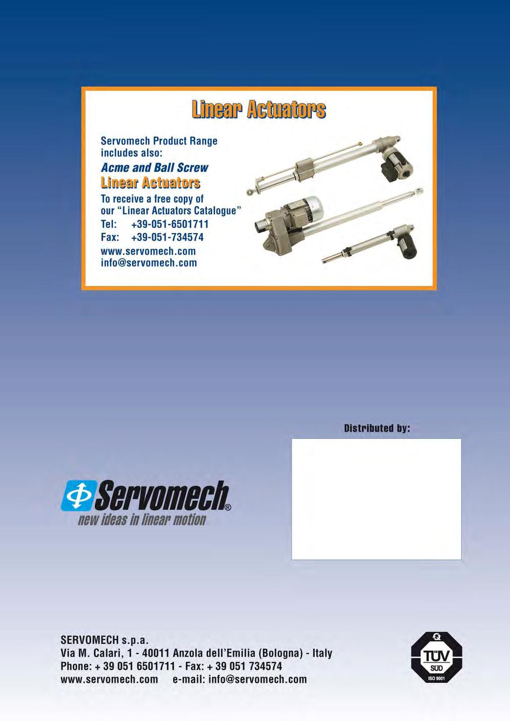
100
Screw jacks with travelling ball nut (Mod.B)
") Screw jacks with travelling ball nut (Md.B).1 MA Series Md.B - STRUCTURAL ELEMENTS 1 2 11 16 17 1 5 4 19 15 6 18 9 20 1 10 14 8 7 12 1 - ball screw in quenched and tempered ally steel 11 - lw cver 2 -
Screw jacks with travelling ball nut (Md.B).1 MA Series Md.B - STRUCTURAL ELEMENTS 1 2 11 16 17 1 5 4 19 15 6 18 9 20 1 10 14 8 7 12 1 - ball screw in quenched and tempered ally steel 11 - lw cver 2 -
Linear actuators CLA Series and CLB Series
 Linear actuatrs CLA Series and CLB Series CLA-CLB Series, size 0-40 CLA-CLB Series, size 50 102 Linear actuatrs CLA Series and CLB Series.1 MANUFACTURING FEATURES Input drive: wrm gear - precisin helical
Acme Screw Jacks. Catalogue
 Acme Screw Jacks Catalogue SERVOMECH Screw Jacks MA Series Screw Jacks - high efficiency Max. duty cycle: travelling screw: 40 % over 10 min (30 % over 1 hour) travelling nut: 30 % over 10 min (20 % over
/2017. Flexline rapid clamping systems with drive chain clamping element, T-slot and adjustment track
 Traveling unit chain (adjustment track) in 3 lengths s in varius designs Mtr Advantages 8 different clamping elements 4 different T-slts 3 different adjustment tracks drive mtr and die mnitr attachable
AN / ANR Series Characteristic Highlights
 AN / ANR Series Characteristic Highlights Planet gears rtate n slid uncaged needle rller bearings fr increased stiffness and the maximum number f cntact pints. Hardened thrust washers allw the precise
Motorized Pulley 165E, Ø 165 mm
 Mtrized Pulley 165E, Ø 165 mm Mtrized Pulley 165E, with machined helical gear b, perfrms an efficiency, in a cmpact diameter f 165 mm nly. With a min RL f 400 mm and and pwers ranging frm 0.11kW t 1.5kW
MG1 TM MAGNETIC SUPER-COMPACT SYSTEM FILTER
 MG1 TM MAGNETIC SUPER-COMPACT SYSTEM FILTER CT3070.0_01 EN June 2016 Patent applicatin n. 202015000064159 Super cmpact Retains all impurities Fights crrsin Increases the lifespan f the biler Maintains
MG1 TM COMPACT MAGNETIC SYSTEM FILTER
 MG1 TM COMPACT MAGNETIC SYSTEM FILTER CT3070.0_00 EN Nvember 2015 Patent applicatin n. 202015000064159 Super cmpact Retains all impurities Fights crrsin Increases the lifespan f the biler Maintains ptimum
HYDRAULIC BEARING PULLER
 HYDRAULIC BEARING PULLER Parag Ambre 1, Akash Muppid 2, Prf. Nitin Mre 3, Anil Birajdar 4, Sandip Barathe 4 1,2,4,5 BE Mechanical, Dr. D.Y. Patil Schl f Engineering, Pune. 3 Faculty, Dr. D.Y. Patil Schl
Motorized Pulley 138E, Ø 138 mm
 Mtrized Pulley 138E, Ø 138 mm Mtrized Pulley 138E, with machined helical gear b, perfrms an efficiency, in a cmpact diameter f 138 mm nly. With a min RL f 300 mm and and pwers ranging frm 0.10 t 075kW
Large scale high speed machining center
 www.apeccnc.cm Large scale high speed machining center Designed fr heavy cutting, high-speed cutting and high precisin parts machining f varius industries. Car fender finishing Aerspace rib parts 5-axis
Complete Solutions for Industrial Valves
 Butterfly Valves Cmplete Slutins fr Industrial Valves NEWAY VALVE Cat.n.:E-BFV-2006 T Series: Sft Seated Cncentric Butterfly Valve Figure Numbers 12 TC 1 W G WCB 338 Neway figure numbers are designed t
TECHNICAL SPECIFICATION. SPC-4T Stirling Process Cryogenerator
 TECHNICAL SPECIFICATION SPC-4T Stirling Prcess Crygeneratr Reference 80 8044_00 Issue Date April 20, 2016 Stirling Crygenics is a registered trade name f DH Industries BV Fr mre infrmatin n the Stirling
Motorized Pulley 320L, 320M & 320H, Ø in. (321 mm)
") Mtrized Pulley 320L, 320M & 320H, Ø 12.6 in. (321 mm) Our 12.6 diameter Mtrized Pulley range fers three different perfrmance levels fr BULK applicatins: - L fr Light duty - M fr Medium duty - H fr Heavy
Mtrized Pulley 320L, 320M & 320H, Ø 12.6 in. (321 mm) Our 12.6 diameter Mtrized Pulley range fers three different perfrmance levels fr BULK applicatins: - L fr Light duty - M fr Medium duty - H fr Heavy
About Asia Pacific Elite Corp.
 APEC Wide ranges f large-scale machining centers www.apeccnc.cm X=2~12 m Y=2.0~.0 m Rapid traverse=60 m/min X=.2~6.2 m Y=2.~.4 m Rapid traverse=12~20 m/min Abut Asia Pacific Elite Crp. Creating benchmarks
D-Sub adaptor Cable clamps for metric cable entries Cable clamps for PG cable entries Further Accessories
 Cntents Accessries Page D-Sub adaptr............................................... 40.02 Han Split Hd.............................................. 40.04 Cable clamps fr metric cable entries..............................
DC Motors LAK Catalogue-2009/10 E. LAK 2000 Serie kw 0,3-30 HP 4-75Nm. t-telectric.com
 DC Mtrs LAK 2080-2132 Catalgue-2009/10 E LAK 2000 Serie 080-132 0.4-22 kw 0,3-30 HP 4-75Nm t-telectric.cm List f cntents Intrductin... p. 4 Optins... Applicatin data... Bearing data... Output data... Dimensin
E+ Battery Care Guide
 Electric Mtin Systems, LLC 45150 Business Curt, Suite 300 Dulles, VA 20166 USA E+ Battery Care Guide Welcme! Yur E+ Hub Battery Pack is a pwerful, sphisticated, and imprtant part f yur E+ Electric Bicycle.
Mag-Nus2 MAGNETIC, SELF CLEANING, DIRT SEPARATOR
 Mag-Nus2 MAGNETIC, SELF CLEANING, DIRT SEPARATOR CT3548.0_00 EN Octber 2017 Retains all impurities Self-cleaning Excellent hydraulic prperties Can be munted n vertical, hrizntal and diagnal piping Increases
Introduction Specifications Structure & Performance Assembly Folding Operation Care & Maintenance...
 n Intrductin... 3 Specificatins... 4 Structure & Perfrmance... 5 Assembly... 6 Flding... 7 Operatin... 8-12 Care & Maintenance... 13-15 2 P a g e Read and fllw all instructins, warnings, and ntes in this
Contents. Han Q Technical characteristics Han Q 5/ Han Q 5/ Technical characteristics Han Q 7/
 Cntents Page Technical characteristics 5/0.............................. 13.10 5/0.................................................. 13.11 Technical characteristics 7/0.............................. 13.14
Gearbox Installation Manual
 Gearbx Installatin Manual Rtrk Gears HOB/MPR & HOS/MPR ranges (Electrnic cpy available n www.rtrk.cm)! This manual cntains imprtant safety infrmatin. Please ensure it is thrughly read and understd befre
FIRST: Top battery (closest to the arm) SECOND: Middle battery. LAST: Top battery (furthest from arm)
 SECOND: Middle battery. LAST: Top battery (furthest from arm)") Hw t Install the Batteries Hw t Hld the Lamp: The InteliEnergy Lamp selectin switches utilize the same technlgy as cell phnes: Capacitive Tuch. This assures the ultimate in lngevity because there are n
Hw t Install the Batteries Hw t Hld the Lamp: The InteliEnergy Lamp selectin switches utilize the same technlgy as cell phnes: Capacitive Tuch. This assures the ultimate in lngevity because there are n
NEW HOLLAND. Front Linkage Front PTO
 NEW HOLLAND Frnt Linkage Frnt PTO Great technlgy fr the wrk in the field Optimum quality latest technlgy cmpact design use wrldwide SAUTER Cnceptin SAUTER Frnt Linkage Develpment, prductin, sales and technical
CLAAS. Front Linkage Front PTO
 CLAAS Frnt Linkage Frnt PTO Great technlgy fr the wrk in the field Optimum quality latest technlgy cmpact design use wrldwide SAUTER Cnceptin SAUTER Frnt Linkage Develpment, prductin, sales and technical
Design Standard - Fume Hoods & Fume Hood Exhausts
 1.0 Intrductin Design Standard - Fume Hds & Fume Hd Exhausts The fume hd is the primary cntrl device in mst labratries fr prtecting emplyees and students frm expsure t hazardus chemicals. It is als an
FC Sıcaklık Serisi FLAMEPROOF SWITCHES. IECEx CoC
 FLAMEPROOF SWITCHES SPECIFIER'S GUIDE FOR PRESSURE SWITCHES PRESSURE DIFFERENCE SWITCHES VACUUM SWITCHES TEMPERATURE SWITCHES APPROVED with IECEx CC CCOE apprved KLPL apprved FC Sıcaklık Serisi 7 Using
PSS INSTALLATION INSTRUCTIONS
 PSS INSTALLATION INSTRUCTIONS Imprtant - Read Befre Starting! Befre starting yur installatin carefully read the fllwing warnings and instructins. Failure t prperly fllw the warnings and instructins culd
Compact Safedrive with built-in Safety Brake. innovative drive systems for industrial doors. Variable Speed Safedrive with built-in Safety Brake
 GfA-ELEKTROMATEN Chain Drive Operatr fr Rller Shutter Cmpact Safedrive with built-in Safety Brake Safedrive with built-in Safety Brake Chain Drive with separate Safety Brake Fire Shutter Operatr innvative
Hydraulic pumps and hydraulic power packs type Z (gear pumps)
") Hydraulic pumps and hydraulic pwer packs type Z (gear pumps) Operating pressure p max = 210 bar Delivery flw Q max = 135 lpm (150 rpm) Gem. displacement V g max = 87.8 cm 3 /rev. 1. General infrmatin Hydraulic
Hydraulic pumps and hydraulic pwer packs type Z (gear pumps) Operating pressure p max = 210 bar Delivery flw Q max = 135 lpm (150 rpm) Gem. displacement V g max = 87.8 cm 3 /rev. 1. General infrmatin Hydraulic
100 KW / 125 KVA POWERED by
 100 KW / 125 KVA POWERED by MODEL Tritn Pwer is a wrld leader in the design, manufacture f statinary, mbile and rental generatr sets and Pwer Mdules frm 10 t 2000 kw. Thrugh ur cmmitment t quality we manufacture
A very common arrangement for oil lubricated stern tube bearings. A simplex seal arrangement is fitted to both inner and outer ends.
 Simplex shaft seal A very cmmn arrangement fr il lubricated stern tube bearings. A simplex seal arrangement is fitted t bth inner and uter ends. The replaceable chrme liner prevents damage t the prp shaft
 www.motiontech.com.au Copyright SERVOMECH This catalogue contents are under publisher copyright and may not be reproduced unless permission is agreed. Every care has been taken to ensure the accuracy of
BIG-VUE Series Meter
 USA SINCE 1936 RELIABILITY BEYOND MEASURE Technical Data Sheet BIG-VUE Series Meter File N. E471457 LAC DU FLAMBEAU,WI LAC DU FLAMBEAU,WI 1/2 The mving irn & mving cil panel meters sizes 2 " 1/2, 3 " are
AS 50. Experience Of your worksite
 EN Fr decades, MECALAC has been develping and prducing high-quality and innvative wheel laders at the Büdelsdrf site in Nrthern Germany. With ur articulated laders, furwheel steered frnt laders and furwheel
ABTQ-103 rev 01 Last review:
 INSTALLATION, OPERATION & MAINTENANCE INSTRUCTIONS FOR ABTECH PCS Cntrl Statin Purpse f Instructins Wrking in hazardus areas, the safety f persnnel and plant depends n cmplying with all relevant safety
Lithium Battery Shipping Overview
 Lithium batteries are used in many electrnic devices such as cameras, cell phnes, laptp cmputers, medical equipment and pwer tls. When shipping r imprting lithium batteries, including thse cntained in
Q U O T A T I O N REV.0 Stick-Pack MS18 6 lanes CUSTOMER: PRODUCT SPECIFICATIONS:
 Santa Perpetua de M., 4th July 2008 Q U O T A T I O N 08070802 REV.0 Stick-Pack MS18 6 lanes CUSTOMER: PRODUCT SPECIFICATIONS: PRODUCT: 2 COMPONENTS: A) SOUP POWDER B) CROUTONS OR VEGETABLES FILL DOSE:
Reliable and Intelligent Energy
 BRAND: MODEL: TYPE: RANGE: Descriptin : AEM MTU725ES STANDARD MTU HEAVY STANDARD 725 KVA Open Generating Set STANDARD SERIES General Specificatins f the Generating Set GENSET DATA CONTINUOUS POWER (PRP)
Parts Checklist: XJ Front 3-Link Long Arm Upgrade Installation Instructions *BOX 1* *BOX 2* Jeep Cherokee XJ
 XJ Frnt 3-Link Lng Arm Upgrade Installatin Instructins 84-01 Jeep Cherkee XJ Parts Checklist: *BOX 1* Instructins Invice Lg decal 10001 (1) Rck-Link decal 13287 (2) Irnrckffrad.cm decal (1) Subframe center
Screw jacks MA Series
 Screw jacks MA Series Screw jacks MA Series with travelling screw (Mod.A) STRUCTURAL ELEMENTS 1 10 11 8 7 6 1 3 13 4 9 14 8 11 10 5 6 7 1 - acme screw in steel C 43 (UNI 7847), whirled thread - worm shaft
Motorized Pulley 138E, Ø 5.45 in. (138 mm)
") Mtrized Pulley 1E, Ø 5.45. (1 mm) Mtrized Pulley 1E, with mached helical gearb, perfrms with a gearb efficiency f 95% f nmal pwer, a cmpact diameter f 5.45 ches. With a mimum rller length (RL) f 11.81
Mtrized Pulley 1E, Ø 5.45. (1 mm) Mtrized Pulley 1E, with mached helical gearb, perfrms with a gearb efficiency f 95% f nmal pwer, a cmpact diameter f 5.45 ches. With a mimum rller length (RL) f 11.81
CS369-R51I Thank you very much for purchasing our air conditioner.
 OWNER'S MANUAL CONDITIONER REMOTE CONTROLLER ILLUSTRATION The design and specificatins are subject t change withut prir ntice fr prduct imprvement. Cnsult with the sales agency r manufacturer fr details.
4 Wheel Electric Forklift Trucks B40X / B45X / B50X-5
 R 4 Wheel Electric Frklift Trucks B40X / B45X / B50X-5 8,000lb t 10,000lb Capacity B40X / B45X / B50X-5 8,000lb t 10,000lb Capacity 80 VOLT Slid Sft Rider Tire PSC0708A3v2 AUTHORIZED DEALER Dsan Industrial
Parts Checklist: ZJ Front 3-Link Long Arm Upgrade Installation Instructions *BOX 1* *BOX 2* Jeep Grand Cherokee ZJ
 ZJ Frnt 3-Link Lng Arm Upgrade Installatin Instructins 93-98 Jeep Grand Cherkee ZJ Parts Checklist: *BOX 1* Instructins Invice Lg decal 10001 (Qty: 1) Rck-Link decal 13287 (2) Irnrckffrad.cm decal (1)
Rejuvenation Instructions
 Rejuvenatin Instructins #521 200A Elbws UPR This NRI cvers the fllwing: Hw t prepare 200amp pre-mlded elbws fr injectin. Hw t install and re-infrce an injectin elbw. Hw t size an injectin elbw t match
PRAIRIE 360 4X4 (KVF360-A/C), PRAIRIE 360 2X4 (KVF360-B), PRAIRIE 650 4X4 (KVF650-A/B), PRAIRIE 700 4X4 (KVF700-A/B/D),
, PRAIRIE 360 2X4 (KVF360-B), PRAIRIE 650 4X4 (KVF650-A/B), PRAIRIE 700 4X4 (KVF700-A/B/D),") SERVICE REPLACES: Please discard ATV 07-02 dated 4/5/07 MODEL: PRAIRIE 360 4X4 (KVF360-A/C), PRAIRIE 360 2X4 (KVF360-B), PRAIRIE 650 4X4 (KVF650-A/B), PRAIRIE 700 4X4 (KVF700-A/B/D), KFX700 (KSV700-A/B/C),
SERVICE REPLACES: Please discard ATV 07-02 dated 4/5/07 MODEL: PRAIRIE 360 4X4 (KVF360-A/C), PRAIRIE 360 2X4 (KVF360-B), PRAIRIE 650 4X4 (KVF650-A/B), PRAIRIE 700 4X4 (KVF700-A/B/D), KFX700 (KSV700-A/B/C),
The MODUM Fire Escape Ladder
 The MODUM Fire Escape Ladder The MODUM Fire Escape Ladder is elegantly designed fr permanent wall munting - and it is ready fr use in secnds. The MODUM Fire Escape Ladder is designed and manufactured in
Dana Spicer Driveshaft. Installation Guide DSIG-3311 March 2004
 Dana Spicer Driveshaft Installatin Guide DSIG-3311 March 2004 Safety Precautins General Safety Infrmatin T prevent injury t yurself and /r damage t the equipment: Read carefully all wners manuals, service
Tips & Technology For Bosch business partners
 Tips & Technlgy Fr Bsch business partners Current tpics fr successful wrkshps N. 35/2011 Gasline injectin Invented fr life Lambda sensr Knw-hw frm the market leader Bsch, innvative cmpany and wrld's largest
Reliable and Intelligent Energy
 BRAND: MODEL: TYPE: RANGE: Descriptin : AEM DW200EI SOUNDPROOFED DEUTZ SOUNDPROOFED 200 KVA Sundprfed Genset SOUNDPROOFED SERIES General Specificatins f the Generating Set GENSET DATA CONTINUOUS POWER
Double throttle/check valve type Z2FS10
 Duble thrttle/check valve type Z2FS0 NS0 up t,5 Ma up t dm /min WK 450 2 02.200 LICION hrttle/check valve type Z2FS0 0... is used t cntrl main flw rate (r pilt flw rate) in ne directin f flw and t allw
Content. Sincere, Open. To Be The Best Battery Supplier. About Us. Page 3,4 Battery Cell. Page 5,6 Battery Pack
 New Brchure 2017 1/22 CONTENT 2/22 Sincere, Open T Be The Best Supplier Cntent Abut Us Page 3, Page 5,6 Pack Page 7,8 Packs-Lead Acid Replacement Page 9,10 Charger Page 11 BMS Page 12 Slutins Page 13 Slutin
03-06 TJ Long Arm Upgrade Instructions
 Parts List: Instructins Irn Rck Off Rad lg decal (2) Irnrckffrad.cm decal (1) Belly skid plate 85046 (1) Left lng arm frame munt 85121 (1) Right lng arm frame munt 85122 (1) Left LCA munt gusset plate
INVERTER/CHARGERS EVOLUTION SERIES. Off-Grid Power Solutions. How an Inverter/ Charger. Works... ORDER NOW
 D yu yu need reliable AC pwer in a vehicle, remte lcatin r fr emergency back-up? Samlex s inverter/charger is THE chice fr a cmplete ff-grid pwer slutin. Off-Grid Pwer Slutins LUTION SERIES S Sine 1 Pure
4 Wheel Electric Forklift Trucks B22X / B25X / B30X / B35X-5. 4,500lb to 7,000lb Capacity
 4 Wheel Electric Frklift Trucks B22X / B25X / B30X / B35X-5 4,500lb t 7,000lb Capacity A CUSTOMER-DRIVEN DESIGN DRIVE THE DIFFERENCE... ... T GUARANTEE CUSTOMER SATISFACTION Extensive marketplace research
GLOBAL LIFT CORP. Owner s Manual. Rotational Series R-375
 GLOBAL LIFT CORP Owner s Manual Rtatinal Series R-375 684 N Prt Crescent Rd Suite C Bad Axe, MI 48413 Tll Free: 866-712-0606 Fax: 989-269-5902 www.glballiftcrp.cm Page 1 ROTATIONAL SERIES POOL LIFTS R-375
VB 60/ Zero Flow sensitive unloader valve
 Ultim aggirnament: 20/04/18 VB 60/600-400-250 Zer Flw sensitive unlader valve Manuale tecnic: E 272 Pressure regulating valve unlader type with zer setting n delivery line: at gun clsure the water flw
RC Series. Rodless Air Cylinder Contents
 Rdless Air Cylinder D RC 1Z 1X OS- Cntents Features...168 Ordering Infrmatin...169 Specificatins, Weights...170 Frce Data...170 ad and ment Data...171 Cushin Data...172 rting Cnfiguratins/Cylinder Selectin...173
LT-F Compact Treaded All Terrain Surveillance & Inspection Robot
 Rbts, Parts, and Custm Slutins www.superdridrbts.cm Tll Free: (866) SDRbts Phne: (919) 557-9162 Fax: 775-416-2596 1421 E. Brad Street #101 Fuquay Varina, NC 27526 LT-F Cmpact Treaded All Terrain Surveillance
Parts Checklist: WJ Front 3-Link Long Arm Upgrade Installation Instructions *BOX 1* (1) *BOX 2* (1) Jeep Grand Cherokee WJ
 *BOX 2* (1) Jeep Grand Cherokee WJ") Parts Checklist: *BOX 1* 13319 (1) Instructins Lg decal 10001 (Qty: 1) Rck-Link Decal 13287 (2) Irnrckffrad.cm decal (1) Subframe center 92270 (1) Subframe left uter 92256 (1) Subframe right uter 92275
Parts Checklist: *BOX 1* 13319 (1) Instructins Lg decal 10001 (Qty: 1) Rck-Link Decal 13287 (2) Irnrckffrad.cm decal (1) Subframe center 92270 (1) Subframe left uter 92256 (1) Subframe right uter 92275
Motor pumps and hydraulic units type R and RG
 Mtr pumps hydraulic units type R RG Pump units with radial-pistn pumps ace. t D 6010 ready fr installatin peratin Operating pressure p max = 700 bar Delivery flw Q max = 91.2 lpm (at 1450 rpm) Gemetric
OWNER S MANUAL. DCR-205-XX-DC Powered Drum Rotators
 VESTIL MANUFACTURING CORP. 2999 N. Wayne St., Angla, IN 46703 Ph: 260-665-7586 Fax: 260-665-1339 E-mail: sales@vestil.cm Website: www.vestil.cm 0317 DCR-205-DC, MANUAL DCR-205-XX-DC Pwered Drum Rtatrs
High speed spindles for manual tool change
 GMN Paul Müller Industrie GmbH & C. KG Äußere Bayreuther Str. 230 D-90411 Nuremberg Phne: 49 (0) 911-5691-0 Fa: 49 (0) 911-5691-221 Spindle technlgy: Phne: 49 (0) 911-56 91-2 Fa: 49 (0) 911-5691-699 Mail:
GLOBAL LIFT CORP. Owner s Manual. Superior Series Proformance Series S-350 / P-375
 GLOBAL LIFT CORP Owner s Manual Superir Series Prfrmance Series S-350 / P-375 684 N Prt Crescent Rd Suite C Bad Axe, MI 48413 Tll Free: 866-712-0606 Fax: 989-269-5902 www.glballiftcrp.cm Page 1 SUPERIOR
CRUSHER BUCKETS. Made In Italy
 CRUSHER BUCKETS Made In Italy Abut italdem: Italiademlitri srl is the manufacturer f italdem prducts ne f the mst well knwn brands f hydraulic hammers and ne f the market leaders nt nly in Italy but als
INSTALLATION & USER S GUIDE
 REKLUSE MOTOR SPORTS The Rekluse EXP Clutch OVERVIEW INSTALLATION & USER S GUIDE Dc ID: 191-6000 Manual Revisin: 050514 This kit will replace sme f the OEM frictins and drive plates with the EXP disk.
The MODUM Fire Escape Ladder
 The MODUM Fire Escape Ladder The MODUM Fire Escape Ladder is elegantly designed fr permanent wall munting - and it is ready fr use in secnds. The MODUM Fire Escape Ladder is designed and manufactured in
CHAPTER 3 Chilled beam OKNI 300 & 400
 CHAPTER 3 Chilled beam OKNI 300 & 400 The Slid Air chilled beams OKNI 300 and 400 are active chilled beams fr use in suspended ceilings. Air-utflw directin: 2-sided Primary air cnnectin: side r tp Available
BioWave Hydro DI-9200 User Manual
 BiWave Hydr DI-9200 User Manual Assembling Hydr DI 9200: Assembling yur BiWave Hydr DI 9200, is a very shrt and simple prcess. All yu have t d is take the Hydr DI 9200 ut f the bx, make sure its standing
CHAPTER 4 Chilled beam OKNI 450 & 600
 CHAPTER 4 Chilled beam OKNI 450 & 600 The Slid Air chilled beams OKNI 450 and 600 are active chilled beams fr use in suspended ceilings. Air-utflw directin: 2-sided, Primary air cnnectin: side r tp Available
DINAK DWhp 0036 CPD APPLICATIONS MAIN FEATURES MATERIALS AVAILABLE DIAMETERS
 DINAK DWhp DW 2.0 FTG-DWHP2-ENG-100 Twin wall stainless steel mdular duct with inner sealing jint, duble lcking band and intermediate rckwl islatin f 100 kg/m3 f density and 30 mm f thickness APPLICATIONS
SELF-CLEANING FILTER WITH DOUBLE PRESSURE GAUGE
 SELF-CLEANING FILTER WITH DOUBLE PRESSURE GAUGE CT2516.0_00 EN June 2015 Pair f pressure gauges t cntrl the inlet / utlet pressure and filter clgging. Self-cleaning Ensures system efficiency Limited verall
EDBRO RIGID INCLINOMETER
 EDBRO RIGID INCLINOMETER RINC01 Installatin & Operating Instructins E5542 rev 1 (June 2010) Edbr PLC Nelsn Street, Bltn BL3 2JJ UK Tel: +44 (0) 120 4528888 Fax: +44 (0) 120 4531957 E-mail: pstmaster@edbr.cm
Delta RPI-M50A - India. Grid-Tied Solar Inverter RPI-M50A. The Power Behind Competitiveness. Product Features
 The Pwer Behind Cmpetitiveness Delta - India Grid-Tied Slar Inverter Prduct Features Transfrmerless Inverter Dual MPP Trackers Peak Efficiency up t 98.6% Cnnects up t 10 Strings Ergnmic Grip Design Ultra
XJ 4-Link Rear Long Arm Instructions
 Parts Checklist: Instructins Irn Rck Off Rad Decal - (2) Rck-Link Decal 13287 - (2) irnrckffrad.cm Decal - (1) Crssmember - 991162 - (1) Shck crssmember - 91173 - (1) Shck crssmember spacer - 91178 - (2)
Smart Look Series Meter
 File N. E471457 Technical Data Sheet Smart Lk Series Meter 1/2 The mving irn & mving cil panel meters sizes 2 " 1/2, 3 " are hused in a mulded plycarbnate cases which are suitable fr the measurement f
INSTALLATION INSTRUCTIONS FOR PART #47002 WATER / METHANOL INJECTION SYSTEM UNIVERSAL TURBO DIESEL
 Kit Cntents INSTALLATION INSTRUCTIONS FOR PART #47002 WATER / METHANOL INJECTION SYSTEM UNIVERSAL TURBO DIESEL Parts UHO Pump (Ultra High Output) 3 Qt Reservir 10 ft High Pressure Tubing 3 ft Black Wire
Motorized Pulley 320L, 320M & 320H, Ø in. (321 mm)
") Mtrized Pulley 320L, 320M & 320H, Ø 12.64. (321 mm) Our 12.64 diameter Mtrized Pulley range fers three different perfrmance levels fr BULK applicatins: - L fr Light duty - M fr Medium duty - H fr Heavy
Mtrized Pulley 320L, 320M & 320H, Ø 12.64. (321 mm) Our 12.64 diameter Mtrized Pulley range fers three different perfrmance levels fr BULK applicatins: - L fr Light duty - M fr Medium duty - H fr Heavy
Double throttle/check valve type Z2FS6
 Duble thrttle/check valve type ZF N up t,5 Ma up t 0 dm /min WK 4 00 0.0 LICION hrttle/check valve type ZF... is used t cntrl main flw rate (r pilt flw rate) in ne directin f flw and t allw free flw in
PV-70 Remotely Operated Cryogenic Globe Valve Installation, Operation, and Maintenance Manual
 PV-70 Remtely Operated Crygenic Glbe Valve Installatin, Operatin, and NOTIC: Printed cpies are uncntrlled. Page 1 f 12 TABL OF CONTNTS 1. INSTALLATION... 2 2. OPRATION... 4 3. MAINTNANC... 4 4. PRSSUR
GLOBAL LIFT CORP Owner s Manual
 GLOBAL LIFT CORP Owner s Manual 39 N. Caseville Rad PO Bx 559 Pigen, MI 48755 Tll Free: 866-712-0606 Fax: 989-453-3050 www.glballiftcrp.cm Page 1 COMMERCIAL SERIES POOL LIFTS C-350 ~ C-450 ~ C-550 TABLE
Volume 1.1 OPERATIONAL MANUAL MODEL: CG-211Y PIPE TORCH/BURNER MACHINE. by BLUEROCK Tools
 Vlume 1.1 OPERATIONAL MANUAL MODEL: CG-211Y PIPE TORCH/BURNER MACHINE by BLUEROCK Tls UNPACKING THE ITEM Cautin: This machine is packed tgether with items that may be sharp, ily and verly heavy bjects.
The E-Brake. Content: Basic principle The advantages The models The features
 The E-Brake Cntent: Basic principle The advantages The mdels The features Belt & Pully drive Basic principle Serv electrnic Return spring O-Frame cnstructin Hw it wrks The Advantages Basic principle E-Brake
MEDMASTER TROFFER Luminaires for MRI/Imaging Suites LED MRIT SERIES
 MEDMASTER TROFFER Luminaires fr MRI/Imaging Suites PRODUCT FEATURES: Recessed munt Grid; 2' 2', 2' 4' Nn-ferrus cnstructin safe fr sensitive MRI equipment High-utput, high-cri LED lamp ptins NSF2 rating
Tools Required. Installation. Step 1. Headlight lense removal (Driver's side shown, Passenger side similar)
") Tls Required Phillips Screw Driver (crner lamps) Flat Head Screw Driver (ptinal fr headlight cver) Pliers (handy t have) Electrical Tape Sturdy Cpper Wire (t use as a wire fish) 10mm Scket r Wrench (grund
Tls Required Phillips Screw Driver (crner lamps) Flat Head Screw Driver (ptinal fr headlight cver) Pliers (handy t have) Electrical Tape Sturdy Cpper Wire (t use as a wire fish) 10mm Scket r Wrench (grund
Installation instructions: 13 Pin Electrical system for towing hitch
 General data Part number Westfalia Vehicle Manufacturer Vehicle 321 538 300 153 ZGB 1T0 055 204 Vlkswagen Turan MY 2003> 321 538 391 105-005 - 33/07 Imprtant ntes Read the installatin manual prir t starting
Rapid Concept Design Process for EV And HEV, Including Fuel Economy Robustness. Barry James Chief Technical Officer September 2015
 Rapid Cncept Design Prcess fr EV And HEV, Including Fuel Ecnmy Rbustness Barry James Chief Technical Officer September 2015 Cntents Strategy fr Fuel Ecnmy Imprvements Case Studies Reductin in lsses thrugh
SWP200 SERIES: PHOTOVOLTAIC KITS FOR WATER PUMPING
 File ref.: KITswp0_ing Rev. 00-04.0 SWP0 SERIES: PHOTOVOLTAIC KITS FOR WATER PUMPING Water is ne f the few resurces, withut which mankind cannt d. Man has t supply with certain quantities f water in rder
Delta RPI Commercial Series. Grid-Tied Solar Inverter RPI-M12 / RPI-M15A / RPI-M20A / RPI-M30. The Power Behind Competitiveness.
 The Pwer Behind Cmpetitiveness Delta RPI Cmmercial Series Grid-Tied Slar Inverter RPI-M12 / RPI-M15A / RPI-M20A / RPI-M30 Prduct Features Transfrmerless Inverter Dual MPP Trackers Peak Efficiency up t
TADANO GR300EX-1. 30t ROUGH TERRAIN CRANE SPECIFICATION & LOAD CHART
 TADANO GR300EX-1 30t ROUGH TERRAIN CRANE SPECIFICATION & LOAD CHART HYDRAULIC ROUGH TERRAIN CRANE GR-300EX Left-hand steering GENERAL DATA CRANE CAPACITY 30,000 kg at 3.0 m BOOM 4-sectin, 9.7 m - 31.0
WELCOME. WEB LOCATION Los Angeles, CA
 WELCOME Thank yu fr chsing AC Infinity. We are cmmitted t prduct quality and friendly custmer service. If yu have any questins r suggestins, please dn t hesitate t cntact us. Visit www.acinfinity.cm and
Operation & Maintenance Manual For Commercial Use Only
 Operatin & Maintenance Manual Fr Cmmercial Use Only SWB 26/8 Battery Sweeper 2 Table f cntent 1 Safety infrmatin... 4 1.1 Safety and Warning Symbls... 4 1.2 General infrmatin... 4 1.3 Operating infrmatin...
VEHICLE ACTIVATED SPEED LIMIT SIGNS
 VEHICLE ACTIVATED SPEED LIMIT SIGNS TRS-VASL VEHICLE ACTIVATED SPEED LIMIT SIGNS Vehicle Activated Speed Limit (VASL) signs measure the speed f appraching vehicles. If the speed f the vehicle is higher
DriveCam Unit Installation Instructions
 DriveCam Unit Installatin Instructins Installatin f the DriveCam Unit is nt cmplicated, thugh care must be taken t avid specific prblems. Sme vehicles require additinal cnsideratin t determine the ptimum
WORLD COAL AUGUST VOLUME 20 NUMBER World Leader in Material Handling and Coal Preparation
 WORLD COAL AUGUST 2011 AUGUST 2011 - VOLUME 20 NUMBER 08 www.energyglbal.cm Wrld Leader in Material Handling and Cal Preparatin Smth peratins, n s r a L d i v Da., C n t r e t s e A.W. Chnes a simple US,
Delta RPI-M50A. Grid-Tied Solar Inverter RPI-M50A. The Power Behind Competitiveness. Product Features
 The Pwer Behind Cmpetitiveness Delta Grid-Tied Slar Inverter Prduct Features Transfrmerless Inverter Dual MPP Trackers Peak Efficiency up t 98.6% Cnnects up t 12 Strings Ergnmic Grip Design Ultra Cmpact
EnergyBar 6. Setup Guide
 EnergyBar 6 Setup Guide WELCOME Cngratulatins n yur purchase f the Apex EnergyBar 6! The EnergyBar 6 allws the Apex system t cntrl up t six 230 vlt items such as lights, pumps, fans, heaters, chillers
Auxiliary Power Units. Kevin Centek Non-Primary Systems Team Leader. UNCLASSIFIED: Dist A. Approved for public release
 Auxiliary Pwer Units Kevin Centek Nn-Primary Systems Team Leader Reprt Dcumentatin Page Frm Apprved OMB N. 0704-0188 Public reprting burden fr the cllectin f infrmatin is estimated t average 1 hur per
Firefly International Energy Co. Inc.
 Firefly Internatinal Energy C. Inc. http://www.fireflyenergy.cm/ Future : Lead-Carbn = Firefly (Advanced Lead- Acid Battery) Firefly s revlutinary battery technlgy was brn in the Research and Develpment