FRONT DOOR LOCK ACTUATOR (G531598)
|
|
|
- Ginger Lambert
- 5 years ago
- Views:
Transcription


1 PUBLISHED: 11-MAY XK RANGE (X150), HANDLES, LOCKS, LATCHES AND ENTRY SYSTEMS FRONT DOOR LOCK ACTUATOR (G531598)
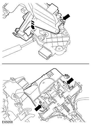
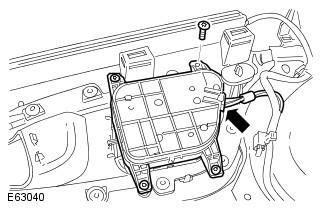
2 REMOVAL AND INSTALLATION REMOVAL 1. Remove the window regulator. For additional information, refer to: Front Door Window Regulator ( Glass, Frames and Mechanisms, Removal and Installation). 2. Release the door latch. Remove the 3 Torx bolts. Disconnect the 3 electrical connectors. 3.
3 Remove the door lock cylinder. Remove the Torx screw. 4. Release the front door exterior handle. Disconnect the electrical connector. 5.
4 Remove the front door exterior handle. Release from the door handle mechanism. 6. Remove the door handle mechanism and latch assembly. Remove the Torx screw. Release the retainer. 7. NOTE: Do not disassemble further if the component is removed for access only.
5 Detach the door release cable from the door handle mechanism. Carefully release the clips. 8. Detach the door lock cable from the door latch. Carefully release the clips. 9.
6 Remove the door handle mechanism and latch assembly security panel. Drill out the rivet. Release the 2 clips. INSTALLATION 1. Install the door handle mechanism and latch assembly security panel. Secure in the clips. Install the new rivet. 2. Attach the door lock cable to the door latch. Secure in the clips. 3. Attach the door release cable to the door handle mechanism. Secure in the clips.
7 4. Install the door handle mechanism and latch assembly. 5. Install the front door exterior handle. Attach to the door handle mechanism. 6. Secure the front door exterior handle. Connect the electrical connector. 7. Install the door lock cylinder. Tighten the Torx screw to 6 Nm (4 lb.ft). 8. Secure the door latch. Tighten the Torx bolts to 7 Nm (5 lb.ft). Connect the electrical connectors. 9. Install the window regulator. For additional information, refer to: Front Door Window Regulator ( Glass, Frames and Mechanisms, Removal and Installation). PUBLISHED: 11-MAY XK RANGE (X150), GLASS, FRAMES AND MECHANISMS FRONT DOOR WINDOW REGULATOR (G537438)
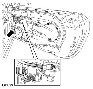
8 REMOVAL AND INSTALLATION REMOVAL 1. Raise the window glass. 2. Remove the cover and disconnect the battery ground cable. For additional information, refer to: Specifications (414-00, Specifications). 3. Remove the front door trim panel. For additional information, refer to: Front Door Trim Panel ( Interior Trim and Ornamentation, Removal and Installation). 4. Remove the window regulator motor. Disconnect the electrical connector. Remove the 3 Torx screws. 5.
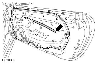
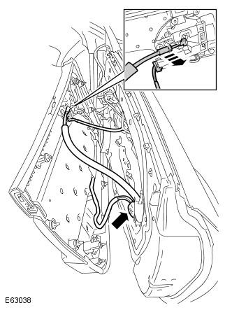
9 Release the front door inner weathershield. Disconnect the 3 electrical connectors. Release the 9 wiring harness clips. 6. Remove the front door inner weathershield. Remove the 12 Torx bolts. Release the front door interior handle cable.
10 7. Carefully remove the outer waist seal. Release each end of the seal from the door frame. 8. Remove the front door window glass. Remove the 2 Torx bolts. Collect the clamp and rubber washer. 9. Remove the window regulator assembly. Release the rubber lining from the glass channel. Remove the 4 Torx screws. Remove the bolt. Remove the nut. INSTALLATION 1. Install the window regulator assembly. Tighten the nut to 10 Nm (7 lb.ft). Tighten the bolt to 10 Nm (7 lb.ft). Install and tighten the Torx screws. Install the rubber lining to the glass channel. 2. Install the front door window glass.
11 Attach the clamp and rubber washer. Install the Torx bolts, but do not tighten fully at this stage. 3. Install the outer waist seal. 4. NOTE: The window must be fully raised when carrying out measurements. Align the front door window glass longitudinally. Position the window, forwards or rearwards, glass edge should be 44mm from edge of door as shown in dimension 'A'. Tighten the Torx bolts to 8 Nm (6 lb.ft). 5. NOTE: To adjust the window hold the locknut and turn the centre spindle.
12 Align the front door window glass horizontally. Release the retaining nut. Align the glass to door, glass should be 12mm from door as shown in dimension 'B'. Tighten the retaining nut to 10 Nm (7 lb.ft). 6. Install the front door inner weathershield. Attach the front door interior handle cable. Tighten the Torx bolt to 10 Nm (7 lb.ft). 7. Secure the front door inner weathershield. Secure the wiring harness clips. Connect the electrical connectors. 8. Install the window regulator motor. Install and tighten the Torx screws. Connect the electrical connector. 9. Install the front door trim panel. For additional information, refer to: Front Door Trim Panel ( Interior Trim and Ornamentation, Removal and Installation). 10. Connect the battery ground cable and install the cover. For additional information, refer to: Specifications (414-00, Specifications).
13 PUBLISHED: 11-MAY XK RANGE (X150), INTERIOR TRIM AND ORNAMENTATION FRONT DOOR TRIM PANEL (G531701)
14 REMOVAL AND INSTALLATION FRONT DOOR TRIM PAD - RENEW ALL DERIVATIVES 0.4 USED WITHINS REMOVAL 1. Remove the exterior mirror trim panel. Release the 3 clips. Disconnect the electrical connector. 2.
15 Release the front door trim panel. Remove the bolt cover. Remove the 3 Torx bolts. Release the 16 clips. 3. NOTE: Do not disassemble further if the component is removed for access only.
16 Remove the front door trim panel. Release the front door interior handle cable. Disconnect the 2 electrical connectors. 4. Remove the front door latch remote control handle. Release from the 5 clips.
17 5. Remove the grab handle cover. Release from the 6 clips. 6. Remove the window control switch. Release from the 3 clips. Disconnect the electrical connector. 7.
18 Remove the seat control switch. Remove the 4 Torx screws. Disconnect the electrical connector. INSTALLATION 1. Install the seat control switch. Connect the electrical connector. Install and tighten the Torx screws. 2. Install the window control switch. Connect the electrical connector. Secure in the clips. 3. Install the grab handle cover. Secure in the clips. 4. Install the front door latch remote control handle. Secure in the clips. 5. CAUTION: Make sure that the cable remains correctly installed to the front door trim panel. Install the front door trim panel. Attach the front door interior handle cable.
19 Connect the electrical connectors. 6. Secure the front door trim panel. Secure in the clips. Tighten the Torx bolts to 10 Nm. Install the bolt cover. 7. Install the exterior mirror trim panel. Connect the electrical connector. Secure with the clips. 8. Check the operation of the door latch remote control handle. With the door closed, check the latch operation of the door latch remote control handle. With the door closed, check the lock operation of the door latch remote control handle.
 Page 1 of 15 2011 Glass, Frames and Mechanisms - Rear Quarter Window Regulator Motor Removal and Installation Removal 1. Remove the rear quarter trim panels. For additional information, refer to: Rear
 Page 1 of 7 Bumpers - Front Bumper Cover Removal and Installation Removal 1. WARNING: Do not work on or under a vehicle supported only by a jack. Always support the vehicle on safety stands. Raise and
DISASSEMBLY. 1 of 9 2/28/ :48 AM 1. DISCONNECT CABLE FROM NEGATIVE BATTERY TERMINAL 2. REMOVE FRONT DOOR ARMREST BASE UPPER PANEL
 1 of 9 2/28/2008 10:48 AM Last Modified: 2-12-2007 1.6 A Service Category: Vehicle Exterior Section: Door/Hatch Model Year: 2008 Model: xb Doc ID: RM000001CE100DX Title: ENGINE HOOD / DOOR: FRONT DOOR:
Removing and installing trim panel
 Removing and installing trim panel vw-wi://rl/a.en-gb.a03.5106.29.wi::31914802.xml?xsl=3 1. oldal, összesen: 1 oldal Removing and installing trim panel Removing Carefully prise out trim panel -1- in direction
FRONT AIR SPRING (G271593)
") PUBLISHED: 11-MAY-2011 2003.50 XJ RANGE (X350), 204-05 VEHICLE DYNAMIC SUSPENSION FRONT AIR SPRING (G271593) REMOVAL AND INSTALLATION 60.32.08 FRONT AIR SPRING - RENEW ALL DERIVATIVES 0.70 USED WITHINS
PUBLISHED: 11-MAY-2011 2003.50 XJ RANGE (X350), 204-05 VEHICLE DYNAMIC SUSPENSION FRONT AIR SPRING (G271593) REMOVAL AND INSTALLATION 60.32.08 FRONT AIR SPRING - RENEW ALL DERIVATIVES 0.70 USED WITHINS
Steering Column - Steering Column Removal and Installation
 Page 1 of 7 Steering Column - Steering Column Removal and Installation Removal WARNING: Take care if releasing the adjustment lever when the column has been removed from the vehicle. The spring is under
Soumatrix speakers installation guide
 Soumatrix 07.2014 Soumatrix speakers installation guide Preface Soumatrix coaxial speakers combine bass and treble loundspeaker in one unit. Just replace the car original bass loudspeakers in each of the
ED 13. ENGINE HOOD / DOOR FRONT DOOR (w/ Power Window) DISASSEMBLY
 DISASSEMBLY") 13 B088092E01 DISASSEMBLY Use the same procedures for both the LH and RH sides. 1. DISCONNECT CABLE FROM NEGATIVE BATTERY TERMINAL 2. REMOVE FRONT DOOR LOWER FRAME BRACKET GARNISH LH (a) Disengage the
13 B088092E01 DISASSEMBLY Use the same procedures for both the LH and RH sides. 1. DISCONNECT CABLE FROM NEGATIVE BATTERY TERMINAL 2. REMOVE FRONT DOOR LOWER FRAME BRACKET GARNISH LH (a) Disengage the
DOORS - REAR TABLE OF CONTENTS
 23-88 DOORS - REAR XJ DOORS - REAR TABLE OF CONTENTS page AIR EXHAUSTER...88....88 DOOR...89....89 DOOR GLASS...89....89 EXTERIOR HANDLE...89....89 HINGE...90....90 INSIDE HANDLE ACTUATOR...90....90 page
Front bumper (Audi RS6)
") 63-1 Front bumper (Audi RS6) Assembly overview 1 - Air inlet grille To remove pull grille forward 2 - Air inlet grille To remove pull grille forward 3 - Screw 2.5 Nm 3x 4 - Bumper cover Together with impact
63-1 Front bumper (Audi RS6) Assembly overview 1 - Air inlet grille To remove pull grille forward 2 - Air inlet grille To remove pull grille forward 3 - Screw 2.5 Nm 3x 4 - Bumper cover Together with impact
2006 Saturn Ion ACCESSORIES & EQUIPMENT Doors - Ion
 POWER DOOR LOCK SWITCH REPLACEMENT Removal Procedure Fig. 28: View Of Power Door Lock Switch 1. Using a flat-bladed tool, pry the switch from the door trim panel enough to expose the locking tabs. 2. Press
DESCRIPTION AND OPERATION > HANDLES, LOCKS, LATCHES AND ENTRY SYSTEMS
 Page 1 of 6 Service Manual: HANDLES, LOCKS, LATCHES AND Print Date: ENTRY SYSTEMS DESCRIPTION AND OPERATION > HANDLES, LOCKS, LATCHES AND ENTRY SYSTEMS 2012 Ford Econoline 5.4L Eng E350 Super Duty NOTE:
 2//2010 Section 01-14A: Handles, Locks, Latches and Mechanisms Workshop Manual REMOVAL AND INSTALLATION Procedure revision date: 03/16/1998 Latch, Door Front 1. Position door glass in the up position.
1 of 2 5/17/17, 1:22 PM
 1 of 2 5/17/17, 1:22 PM Trim Molding, Removing and Installing Special tools, testers and auxiliary items required Wedge Set (T10383) Removal Wedge (T40233) Removing - Starting at the front, pry the trim
Window Glass Front Door
 SECTION 501-11: Glass, Frames and Mechanisms 2000 Expedition/Navigator Workshop Manual REMOVAL AND INSTALLATION Procedure revision date: 06/17/1999 Window Glass Front Door Removal 1. Remove the front door
Outside Rear View Mirror, Remove and Install
 102989Outside Rear View Mirror, and file://c:\program Files\cosids\DATA\TMP\00102989.rtf.html Page 1 of 2 Outside Rear View Mirror, and 1. Move sash window downwards 2. Detach panel for front door inside
DESCRIPTION AND OPERATION > HANDLES, LOCKS, LATCHES AND ENTRY SYSTEMS
 Page 1 of 5 Service Manual: HANDLES, LOCKS, LATCHES AND Print Date: ENTRY SYSTEMS DESCRIPTION AND OPERATION > HANDLES, LOCKS, LATCHES AND ENTRY SYSTEMS 2012 Ford Econoline 5.4L Eng E350 Super Duty NOTE:
23-34 BODY COMPONENTS XJ VEHICLES J DOORS INDEX
 23-34 BODY COMPONENTS XJ VEHICLES J DOORS INDEX page Door Alignment Adjustment Major... 47 Door Alignment Adjustment Minor... 46 Door Edge Guard/Edge Protector Strip... 61 Door External Handle... 55 Door
HITCH INSTALLATION INSTRUCTIONS TESLA MODEL 3 PACKAGE: RACK Present MODEL/TRIM: MAKE: YEARS: 2 HOURS TOOLS REQUIRED: PARTS SUPPLIED:
 HITCH INSTALLATION INSTRUCTIONS MAKE: TESLA YEARS: 2017 Present MODEL/TRIM: MODEL 3 WEIGHT CAPACITY TRAILER TONGUE N/A LBS. 200 LBS. PACKAGE: RACK INSTALLATION TIME: 2 HOURS DO NOT EXCEED VEHICLE MANUFACTURE
FRONT DOOR COMPONENTS
 BO4 FRONT DOOR COMPONENTS BO5 ADJUSTMENT OF FRONT DOOR 1. ADJUST DOOR IN FORWARD /REARWARD AND VERTICAL DIRECTIONS Using SST, adjust the door by loosening the body side hinge bolts. SST 0981200010 2. ADJUST
5. Refer to GTR Workshop Manual, section: and disconnect battery ground cable.
 HYDRAULIC HOSE REPAIR REMOVAL PROCEDURE 1. Open door. 2. Turn ignition 'ON'. 3. Power the convertible top to the fully lowered position. 4. Turn ignition 'OFF'. 5. Refer to GTR Workshop Manual, section:
Central locking system
 Page 1 of 11 57-39 Central locking system Assembly overview 1 - Vacuum line 2 - Right-front door lock actuator Removing and installing page 57-12 3 - Vacuum line connectors Disengage harness connectors
Wait at least 90 seconds after disconnecting the cable from the negative (-) battery terminal to disable the SRS system.
 battery terminal to disable the SRS system.") 2012 Camry DISASSEMBLY Hint: Report a problem with this article Use the same procedure for both the RH and LH sides. The procedure described below is for the LH side. PRECAUTION NOTICE: After turning the
2012 Camry DISASSEMBLY Hint: Report a problem with this article Use the same procedure for both the RH and LH sides. The procedure described below is for the LH side. PRECAUTION NOTICE: After turning the
SECOND ROW SEAT BELT SECOND ROW SEAT BELT. Second Row Seat Belt SB-13 EXPLODED VIEW SEAT BELT RETRACTOR < REMOVAL AND INSTALLATION >
 SECOND ROW SEAT BELT Second Row Seat Belt EXPLODED VIEW SECOND ROW SEAT BELT INFOID:0000000012551454 A B C D E F G SB I J K L M N O AWHIA0861ZZ P 1. Seat belt height adjuster (LH/RH) 2. Seat belt retractor
CERTAIN 2005 MODEL YEAR FIVE HUNDRED, MONTEGO AND CERTAIN 2005 AND 2006 MODEL YEAR FREESTYLE VEHICLES DOOR LATCH WATER PROTECTION
 CERTAIN 2005 MODEL YEAR FIVE HUNDRED, MONTEGO AND CERTAIN 2005 AND 2006 MODEL YEAR FREESTYLE VEHICLES LATCH WATER PROTECTION ATTACHMENT III PAGE 1 OF 9 OVERVIEW Depending on vehicle and build date, this
FRONT DOOR COMPONENTS
 BO4 FRONT DOOR COMPONENTS BO5 COMPONENTS (Cont d) BO6 ADJUSTMENT OF FRONT DOOR 1. ADJUST DOOR IN FORWARD/REARWARD AND VERTICAL DIRECTIONS Using SST, adjust the door by loosening the body side hinge bolts.
Removing and installing moulded headliner
 Page 1 of 13 Removing and installing moulded headliner Special tools and workshop equipment required Removal lever -80-200- Front-end hook -3370- Removal wedge -3409- Removing Remove driver's seat: Audi
In area - A -, a proper seal must be made against the top of the window glass.
 Door window, adjusting Page 1 of 3 Audi > B3 > 1994-1998 Body Exterior, Interior 61 - Convertible top, checking and adjusting Door window, adjusting Sections C-C and D-D. Adjust door window so that window
GEAR SELECTOR CABLE. Remove and refit. Removing. Fig. 22
 GEAR SELECTOR CABLE Remove and refit Fig. 22 his operation requires the removal of the centre console side casing. lace the quadrant selector lever in "1". Unscrew the gear selector knob (1, Fig. 22).
Luggage System Fitting Instructions - Sprint ST
 WARNING: Always have Triumph approved parts, accessories and conversions fitted by a trained technician of an authorised Triumph dealer. The fitting of parts, accessories and conversions by a technician
Camec Keyless Entry System Installation Instructions
 Camec Keyless Entry System Installation Instructions Fitment of this Keyless Entry System can be complex. Installation is recommended to be performed by certified RV installers or competent DIY. Damage
Fuel pump unit, changing
 1(11) Fuel pump unit, changing Special tools: 981 2270, 981 2273, 981 2282, 998 5972, 999 5484, 999 5485, 999 5561, 999 5666, 999 5673 Safety See first Safety regulations for handling fuel. Preparation
Side Door Sill Trim Plate Package Installation
 Page 1 of 5 2014 Chevrolet Equinox Equinox, Terrain VIN L Accessory Installation Manual Accessories Interior Accessories Accessories Document ID: 3619390 Side Door Sill Trim Plate Package Installation
Lower Arm ( ) Special Service Tools. Removal.
 Special Service Tools. Removal.") Page 1 of 6 (60.35.02) Special Service Tools Ball joint separator 205-754 (LRT-54-027) Halfshaft remover/replacer 204-506/1 (LRT-60-030/1) Halfshaft remover/replacer 204-506/3 (LRT-60-030/3) Retainers
Page 1 of 6 (60.35.02) Special Service Tools Ball joint separator 205-754 (LRT-54-027) Halfshaft remover/replacer 204-506/1 (LRT-60-030/1) Halfshaft remover/replacer 204-506/3 (LRT-60-030/3) Retainers
OVERHAUL. 1. REMOVE FRONT DOOR LOWER FRAME BRACKET GARNISH LH (a) Using a screwdriver, remove the lower frame bracket garnish.
 Using a screwdriver, remove the lower frame bracket garnish.") OVERHAUL The installation is in the reverse order of the removal. However, when there is a special point concerning the installation, it is indicated. On the RH side, use the same procedures as on the
OVERHAUL The installation is in the reverse order of the removal. However, when there is a special point concerning the installation, it is indicated. On the RH side, use the same procedures as on the
FRAME AND BUMPERS 13-1 FRAME AND BUMPERS CONTENTS
 J FRAME AND BUMPERS 13-1 FRAME AND BUMPERS CONTENTS BUMPERS... 5 BUMPERS... 16 FRAME... 1 FRAME... 10 FRAME INDEX Frame Dimensions... 1 Front Skid Plate... 1 Fuel Filler Hose Splash Shield XJ Vehicles...
GENUINE PARTS INSTALLATION INSTRUCTIONS
 GENUINE PARTS INSTALLATION INSTRUCTIONS 1. DESCRIPTION: Trailer Tow mirror kit (with power and heated) Trailer Tow mirror kit (with power, heated, and memory) 2. APPLICATION: 04 Titan, Armada, QX56 LE,
Installation Manual: Jeep Cherokee Power Lift Gate System
 Installation Manual: Jeep Cherokee Power Lift Gate System Page 1 of 11 NOTE: Installation Precaution Kit Details Power Cable 4120353 1. It is recommended to have this product installed by a professional
Side Channel Mag Drive (SCM) Assembly
 Assembly") Side Channel Mag Drive (SCM) Assembly Side Channel pumps are available with a magnetic drive option. The pump or fluid end remains the same as the mechanical seal pump for repairs. SCM Pumps Pumps all
Side Channel Mag Drive (SCM) Assembly Side Channel pumps are available with a magnetic drive option. The pump or fluid end remains the same as the mechanical seal pump for repairs. SCM Pumps Pumps all
DOOR KIT P/N , APPLICATION BEFORE YOU BEGIN KIT CONTENTS. Verify accessory fitment at Polaris.com.
 DOOR KIT P/N 2882561, 2882562 APPLICATION Verify accessory fitment at Polaris.com. BEFORE YOU BEGIN Read these instructions and check to be sure all parts and tools are accounted for. Please retain these
1. Remove the parcel tray. For additional information, refer to Section
 SECTION 204-02: Rear Suspension 2001 Taurus/Sable Workshop Manual REMOVAL AND INSTALLATION Procedure revision date: 06/19/2003 Strut and Spring Assembly Four Door Removal CAUTION: Suspension fasteners
FUEL PUMP UNIT, REPLACEMENT. Special tools: , , , , , , , ,
 FUEL PUMP UNIT, REPLACEMENT Special tools: 981 2270, 981 2273, 981 2282, 998 5972, 999 5484, 999 5485, 999 5561, 999 5666, 999 5673 Safety See first: Safety regulations for handling fuel See: Service Precautions
Lotus Evora Door Latch Kit Fitting Instructions LSL 594
 The instructions contained within this fitting guide are tailored to be used when renewing the door latch assemblies and ancillary components as provided in the Evora door latch fitting kit, (part number
Front seats. j a t CAUTION! Before beginning repairs on the electrical system: Obtain the anti-theft radio security code. Switch the ignition off.
 j a t Front seats 72-1 CAUTION! Before beginning repairs on the electrical system: Obtain the anti-theft radio security code. Switch the ignition off. Search Advanced Search Disconnect the battery Ground
AUDIO KIT P/N APPLICATION BEFORE YOU BEGIN KIT CONTENTS. Verify accessory fitment at Polaris.com.
 AUDIO KIT P/N 2882696 APPLICATION Verify accessory fitment at Polaris.com. BEFORE YOU BEGIN Read these instructions and check to be sure all parts and tools are accounted for. Please retain these installation
*70200BAG1* 70200BAG FORD F150 GRILLE LIGHT MOUNT
 927020000 *70200BAG1* 70200BAG1 2015-2018 FORD F150 GRILLE LIGHT MOUNT PRIOR TO INSTALLATION Make sure the kit is complete and you have read these instructions thoroughly before beginning installation.
1 of 6 10/31/2017, 1:57 PM. Fig. 19 Automatic Transmission Shift Knob Removal
 1 of 6 10/31/2017, 1:57 PM Fig. 19 Automatic Transmission Shift Knob Removal 2 of 6 10/31/2017, 1:57 PM Fig. 20 Manual Transmission Shift Knob Removal 3 of 6 10/31/2017, 1:57 PM Fig. 21 Removing Accessory
Wheel bearing housing, removing and installing
 Page 1 of 17 40-54 Wheel bearing housing, removing and installing Removing - Remove wheel trim. On light alloy wheels use puller in vehicle tool kit to remove trim cap. - Remove bolt for drive axle. WARNING!
Wiper arm and wiper motor, headlamp, replacing
 "VCC137971 EN 20110112" file://c:\info\vv132007\ie\en\31\vcc137971.htm Page 1 of 2 Wiper arm and wiper motor, headlamp, replacing Removal Preparations Switch off the ignition. Headlamp wiper arm Lift up
TECHNICAL BULLETIN No:
 CIRCULATE TO: TECHNICAL BULLETIN No: Date: 20 MAY 2010 SERVICE PARTS WARRANTY BODY SHOP THIS BULLETIN SUPERSEDES LA501-12; CHANGES ARE LIMITED TO INSTRUCTING TECHNICIANS TO CARRY OUT THIS REPAIR PROCEDURE
ARTICLE BEGINNING COMPONENTS FRONT DOOR Toyota Tacoma
 Page 1 of 17 ARTICLE BEGINNING COMPONENTS Page 2 of 17 Fig. 1: Front Door Components (w/o Power Door Lock & Power Window Regulator) Page 3 of 17 Fig. 2: Front Door Components (W/ Power Door Lock & Power
CENTER BELT SYSTEM INSTALLATION INSTRUCTIONS CARCG121220
 CENTER BELT SYSTEM INSTALLATION INSTRUCTIONS 2013+ DODGE CHARGER Distributed by CARCG121220 Important Notice: Read all instructions before starting the installation of the seat. Before drilling or installing
4. BODY REPAIR. White Body. Without sunroof. With sunroof BODY REPAIR ACTYON SM CHANGED BY EFFECTIVE DATE AFFECTED VIN
 12 5110 4. White Body Without sunroof With sunroof 5110 13 Body Dimensions Side Structure Complete Unit: mm INT EXT REPAIR 14 5110 Engine Compartment Unit: mm 5110 15 Front End Unit: mm INT REPAIR EXT
Front seats. Special tools and equipment. VAS 5094 airbag adapter. Connecting page 72-9.
 Page 1 of 23 72-1 Front seats Special tools and equipment VAS 5094 airbag adapter Connecting page 72-9. Page 2 of 23 72-2 Front seats, removing and installing WARNING! Before starting work on seats, connect
GENERAL INFORMATION HANDLING PRECAUTIONS
 BODY BO1 BO2 BODY GENERAL INFORMATION GENERAL INFORMATION HANDLING PRECAUTIONS Taping When it is possible that the body or parts may be scratched during the operation, apply protective tape before starting
Hood. Hood, removing, installing and adjusting. Page 1 of 11
 Page 1 of 11 55-1 Hood Hood, removing, installing and adjusting 1 - Hood Removing: - Disconnect hose to windshield washer system and unclip. Second person is needed to support and lift hood during removal
Fuel Injector ( )
") Published: Mar 29, 2010 Fuel Injector (196010) Special Service Tools Fuel Injector remover 303-1127 Removal WARNING: Do not smoke or carry lighted tobacco or open flame of any type when working on or near
Published: Mar 29, 2010 Fuel Injector (196010) Special Service Tools Fuel Injector remover 303-1127 Removal WARNING: Do not smoke or carry lighted tobacco or open flame of any type when working on or near
Installation Instructions
 Installation Instructions Page 1 of 15 November 2007 Equipment Parts, Trailer Hitch Version 3.0 Accessory Development These Installation Instructions supersede all previous versions. SUBJECT MODEL TRAILER
Technical Service Bulletin
 1 of 7 14/03/2009 12:28 AM Technical Service Bulletin No.LTB00191 25 November 2008 Subject/Concern: Liftgate Latch Diagnostics Models: Discovery 3 / LR3 VIN-range: 000001 Onwards Markets: All Section:
Rear Door: Service and Repair REAR DOOR
 2007 Toyota Matrix L4-1.8L (1ZZ-FE) Copyright 2013, ALLDATA 10.52 Page 1 Rear Door: Service and Repair REAR DOOR Rear Door 2007 Toyota Matrix L4-1.8L (1ZZ-FE) Copyright 2013, ALLDATA 10.52 Page 2 ISASSEMBLY
Front Door Non-Functional - Latch Replacement
 Page 1 of 6 Home Account Contact ALLDATA Log Out Help DAN GRIMWOOD DAN GRIMWOOD00002 Select Vehicle New TSBs Technician's Reference Component Search: OK 2002 Ford Truck Escape 2WD L4-122 2.0L DOHC VIN
FOLDING TOP HYDRAULIC CYLINDER HOSE IDENTIFICATION
 Page 1 of 50 Service Manual: POWER ROOF SYSTEM AND Print Date: CONVERTIBLE TOP FOLDING TOP HYDRAULIC CYLINDER HOSE IDENTIFICATION Fig 1: View Of Folding Top Hydraulic Cylinder 2006 Pontiac G6 3.9L Eng
Soumatrix speakers installation guide
 Soumatrix speakers installation guide Preface Soumatrix coaxial speakers combine bass and treble loudspeaker in one unit. Just replace the car original bass loudspeaker in each of the front and rear doors.
Brake Upgrade Kit Fitting Instructions Bonneville America
 WARNING: Always have Triumph approved parts, accessories and conversions fitted by a trained technician of an authorised Triumph Dealer. The fitment of parts, accessories and conversions by a technician
Sunroof / Moonroof: All Technical Service Bulletins Body - Water Leaks To The Interior assenger Compartment Water Ingress
 2006 Land Rover LR3 (LA) V8-4394cc 4.4L Page 1 Sunroof / Moonroof: All Technical Service Bulletins Body - Water Leaks To The Interior assenger Compartment Water Ingress FFECTED VEHICLE RANGE: and Rover
American Honda Motor Co., Inc. Page 1 of 11
 2008 ACCORD - Headliner Removal/Installation (page 20-131) Special Tools Required KTC trim tool set SOJATP2014* *Available through the Honda Tool and Equipment Program; call 888-424-6857 SRS components
The steering column is of a modular construction and features easy to service electrical switches.
 file://c:\tso\tsocache\vdtom_5368\svk~us~en~file=svkb4a01.htm~gen~ref.htm Page 1 of 3 Section 11-04A: Steering Column, Ranger DESCRIPTION AND OPERATION 1997 Ranger Workshop Manual Steering Column NOTE:
Window Regulator: Service and Repair Front Door Trim. Armrests. With Power Windows. Front Door Arm Rest. Remove or Disconnect
 1995 Oldsmobile Cutlass Ciera V6-3100 3.1L VIN M SFI Page 1 Window Regulator: Service and Repair Front Door Trim Armrests 1. Plugs from upper and lower armrest openings. 2. Screws from upper and lower
7 Trim and upholstery
 7 Trim and upholstery 71A BODY INTERNAL TRIM 72A SIDE OPENING ELEMENT TRIM 73A NON-SIDE OPENING ELEMENTS TRIM 75A FRONT SEAT FRAMES AND MECHANISMS X79 NOVEMBER 2009 EDITION ANGLAISE "The repair procedures
HANDLEBAR BAG WITH PHONE CHARGER KIT
 HANDLEBAR BAG WITH PHONE CHARGER KIT P/N 2883687; 2883786 APPLICATION Verify accessory fitment at Polaris.com. BEFORE YOU BEGIN Read these instructions and check to be sure all parts and tools are accounted
Replacement Cluster Fascia Replacement
 1 of 12 11/1/2013 9:13 AM SOUL(AM) >2010 > G 2.0 DOHC > Body (Interior and Exterior) Replacement Cluster Fascia Replacement When prying with a flat-tip screwdriver, wrap it with protective tape, and apply
2015+ Mustang Rear Valance Installation Instructions P/N: (R F953) (R F953BS)
 (R F953BS)") 2015+ Mustang Rear Valance Installation Instructions P/N: 421894 (R1315-17F953) 421919 (R1315-17F953BS) 39555 Schoolcraft Rd, Plymouth MI, 48170 800.59.ROUSH 2015+ Mustang Rear Valance Kit Installation
2015+ Mustang Rear Valance Installation Instructions P/N: 421894 (R1315-17F953) 421919 (R1315-17F953BS) 39555 Schoolcraft Rd, Plymouth MI, 48170 800.59.ROUSH 2015+ Mustang Rear Valance Kit Installation
OUTSIDE OF VEHICLE INSIDE OF VEHICLE
 LAND ROVER DEFENDER 90 / 110 / TDi/ TD5/ PUMA Aluminium GULLWING DOOR MKII GWLD009 INSTALL TIME: 3 Hours OUTSIDE OF VEHICLE INSIDE OF VEHICLE IMPORTANT WARNING! IT IS CRITICAL THAT ALL FRONT RUNNER PRODUCTS
TOYOTA FJ CRUISER AIR DAM/LIGHT BAR Preparation
 Preparation Part Number: PT278-35071 Kit Contents Item # Quantity Reqd. Description 1 1 Air Dam / Light Bar Hardware Bag 1 Contents Item # Quantity Reqd. Description 1 2 Screw, M6x33mm, Wafer Head 2 2
RCA PLUG KIT P/N APPLICATION BEFORE YOU BEGIN KIT CONTENTS. Verify accessory fitment at Polaris.com.
 RCA PLUG KIT P/N 2883824 APPLICATION Verify accessory fitment at Polaris.com. BEFORE YOU BEGIN Read these instructions and check to be sure all parts and tools are accounted for. Please retain these installation
Seat belts. Safety precautions for handling pyrotechnic seat belt tensioners WARNING!
 Page 1 of 41 69-1 Seat belts Safety precautions for handling pyrotechnic seat belt tensioners WARNING! Testing, removing, installing and repair work must only be carried out by properly qualified personnel.
ED 42. ENGINE HOOD / DOOR FRONT DOOR (w/o Power Window)
") 42 ENGINE HOOD / DOOR FRONT DOOR (w/o Power Window) (g) (h) Horizontally and vertically adjust the door by loosening the door side hinge bolts. Tighten the door side hinge bolts after the adjustment. Torque:
42 ENGINE HOOD / DOOR FRONT DOOR (w/o Power Window) (g) (h) Horizontally and vertically adjust the door by loosening the door side hinge bolts. Tighten the door side hinge bolts after the adjustment. Torque:
Overview of rear lid trim panels
 Overview of rear lid trim panels Overview of rear lid trim panels 1 - Rear lid trim (bottom) Exploded view and installing 2 - Rear lid trim (top) Exploded view and installing vw-wi://rl/a.en-gb.a00.5a50.39.wi::46107222.xml?xsl=3
CIRRUS AIRPLANE MAINTENANCE MANUAL
 MODEL SR PASSENGER AND CREW DOORS. DESCRIPTION AND OPERATION Serials 000 thru 00: The two crew/passenger doors incorporate a flush-mount outside door handle, key-operated door lock, and a conventional
Installation Manual: Jeep Cherokee Power Lift Gate System
 Installation Manual: Jeep Cherokee Power Lift Gate System Page 1 of 11 NOTE: Installation Precaution 1. It is recommended to have this product installed by a professional to avoid damage caused by improper
SERVICE INSTRUCTION SI Revision 1
 SERVICE INSTRUCTION SI-25-02 Revision 1 TITLE: Aft Seats Inertia Reel Harness Installation (Mod 1229) SUBJECT / REASON / DESCRIPTION: The FBA-2C1 and FBA-2C2 aircraft are equipped with three individual
Body (Interior & Exterior)
") Body (Interior & Exterior) GENERAL... BD - 2 EXTERIOR... BD - 7 INTERIOR... BD -20 BUMPER... BD -33 SEAT... BD -37 BD -2 GENERAL BODY (INTERIOR & EXTERIOR) SPECIFICATIONS ESTC0010 Hood Type Rear hinged,
Body (Interior & Exterior) GENERAL... BD - 2 EXTERIOR... BD - 7 INTERIOR... BD -20 BUMPER... BD -33 SEAT... BD -37 BD -2 GENERAL BODY (INTERIOR & EXTERIOR) SPECIFICATIONS ESTC0010 Hood Type Rear hinged,
SECTION 1A3 - INSTRUMENT PANEL AND CONSOLE
 SECTION 1A3 - INSTRUMENT PANEL AND CONSOLE Click on the button for more information. CAUTION: This vehicle will be equipped with a Supplemental Restraint System (SRS). A SRS will consist of either seat
Lotus Service Notes Section HG
 STEERING SECTION HG Sub-Section Page General Description HG.1 2 Steering Wheel HG.2 2 Upper Column Assembly HG.3 5 Intermediate Column HG.4 9 Front Wheel Alignment & Rack Gaiters HG.5 9 Rack & Pinion Assembly
Technical Information Replaces Technical Information No. 2/98
 Replaces Technical Information No. 2/98 Inner door release does not function Vehicle Type: Model Year: Concerns: Situation: Note: As of 97 (V) Inner door release and bowden cable. Inner door release does
POWER MIRRORS 8T - 1 POWER MIRRORS CONTENTS
 J POWER MIRRORS 8T - 1 POWER MIRRORS CONTENTS page DIAGNOSIS... 1 GENERAL INFORMATION... 1 page SERVICE PROCEDURES... 4 GENERAL INFORMATION Power outside rear view mirrors are an available option on XJ
Trim (general) Lower A-pillar trim, removing and installing
 Lower A-pillar trim, removing and installing") Page 1 of 16 70-72 Trim (general) Lower A-pillar trim, removing and installing - To remove, remove A-pillar bolts 4 (2x). Tightening torque: 1.5 Nm (13 in. lb) - Remove door seal -2- in area of A-pillar
Page 1 of 16 70-72 Trim (general) Lower A-pillar trim, removing and installing - To remove, remove A-pillar bolts 4 (2x). Tightening torque: 1.5 Nm (13 in. lb) - Remove door seal -2- in area of A-pillar
75 5 ENGINE HOOD/DOOR
 OVERHAUL Installation is in the reverse order of the removal. But the installation is indicated only when it has a point. In the RH side, work in the same procedure as in the LH side. 755 750DN01 1. REMOVE
Installation Instructions - D-Series Warming Cabinet Instruction Door for Hinge UseReversal (Glass and Stainless Steel Doors)
") Header Cam Lock Reversal... pg 1-4 Glass Door hinge reversal..... pg 5-9 Steel Door hinge reversal..... pg 10-13 Remove Panels Before reversing door hinges, the Header Cam Lock assembly must be reversed.
Header Cam Lock Reversal... pg 1-4 Glass Door hinge reversal..... pg 5-9 Steel Door hinge reversal..... pg 10-13 Remove Panels Before reversing door hinges, the Header Cam Lock assembly must be reversed.
INSTALLATION INSTRUCTIONS
 Accessory Application Publication No. INSTALLATION INSTRUCTIONS 12V ACCESSORY SOCKET P/N 08U79-MKC-A00 GL1800/B/BD/D/DA Honda Dealer: Please give a copy of these instructions to your customer. MII 16426
Side Rocker Installation Instructions
 Side Rocker Installation Instructions Guidelines + Trial fit all parts prior to painting + Do not use the side rockers as an attachment point for tie downs + Every 3-6 months, make sure all fasteners are
Chapter 52 DOORS -Title
 Chapter 52 DOORS 52-Title Page 1 January 23, 2012 INTENTIONALLY LEFT BLANK 52-Title Page 2 January 23, 2012 LIST OF EFFECTIVE PAGES Chapter Section Page No. Date 52 52-Title 1 January 23, 2012 2 January
JEEP Wrangler JK/JKU Swing-A-Way Tire Carrier/RotoPpax WARNINGS/CAUTIONS NOTE. INSTALLATION INSTRUCTIONS 2 Door Models 85209
 JEEP Wrangler JK/JKU Swing-A-Way Tire Carrier/RotoPpax 2007-2017 INSTALLATION INSTRUCTIONS Item Kit No. 2 Door Models 85209 4 Door Models 85209 WARNINGS/CAUTIONS These instructions are for both the can
REMOVAL AND INSTALLATION
 501-12-1 Instrument Panel and Console 501-12-1 REMOVAL AND INSTALLATION Instrument Panel Removal CAUTION: Electronic modules are sensitive to static electrical charges. If exposed to these charges, damage
Differential, Disassembling and Assembling Special tools
 Differential, Disassembling and Assembling Special tools VAG 1582 Bearing puller VAG 1582/3 Grip piece VW 412 Thrust disc 40-105 Thrust piece VW 401 Thrust plate VW 402 Thrust plate VW 408 A Punch VW 473
Service Bulletin Trucks
 Volvo Trucks North America, Inc. Greensboro, NC USA Service Bulletin Trucks Date Group No. Page.00 846 05 (6) Outside Mirrors, Vocational VN,VHD, VERSION From build date.00 Outside Mirrors, Vocational
Rear seat. Rear seat, removing and installing. - Using screwdriver -2-, carefully lift headrest guides -3- out of rear backrest -1-.
 Page 1 of 19 72-57 Rear seat Rear seat, removing and installing - Using screwdriver -2-, carefully lift headrest guides -3- out of rear backrest -1-. - Detach rear seat -2- upward out of mounting -3-.
DISASSEMBLY REASSEMBLY
 4 EXTERIOR FRONT BUMPER DISASSEMBLY 1. REMOVE HOOD TO FRONT END PANEL SEAL (a) Using a clip remover, detach the 8 clips and remove the panel seal. 2. REMOVE FRONT BUMPER REINFORCEMENT (a) Using a clip
INSTALL/REMOVAL INSTRUCTIONS: WINDOW LIFT MOTOR
 REMOVAL/INSTALL OF WINDOW REGULATOR (742-269) Ford Mustang 1996 2004 General Tech Tips: Use painter s tape rather than duct tape to secure window. It will not damage paint or leave sticky residue. A plastic
COMPONENTS Toyota RAV ACCESSORIES & EQUIPMENT Front Seat - RAV4
 2005 ACCESSORIES & EQUIPMENT Front Seat - RAV4 COMPONENTS Fig. 1: Identifying Front Seat Components & Torque Specifications FRONT SEAT ASSEMBLY REMOVAL CAUTION: Wear safety gloves, because the cutting