Side Rocker Installation Instructions
|
|
|
- Rosamond Blankenship
- 6 years ago
- Views:
Transcription
.")
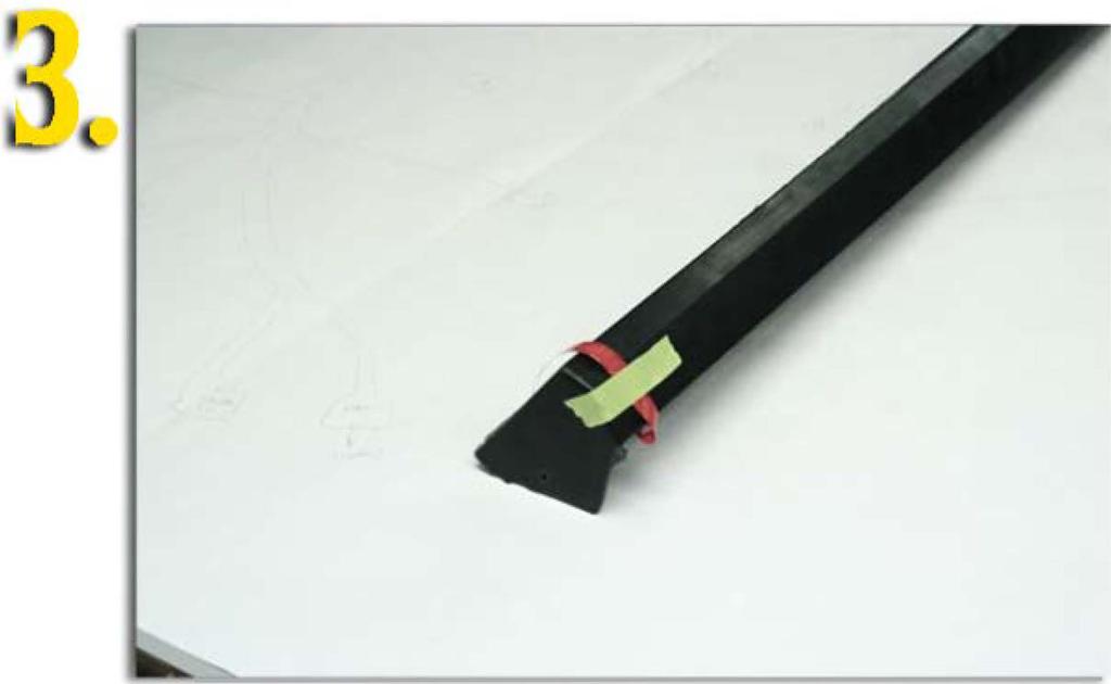
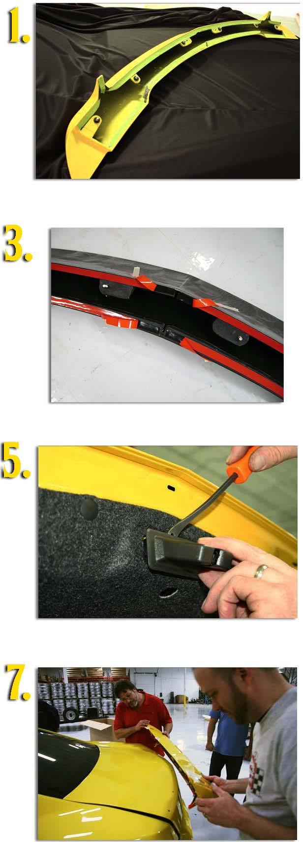
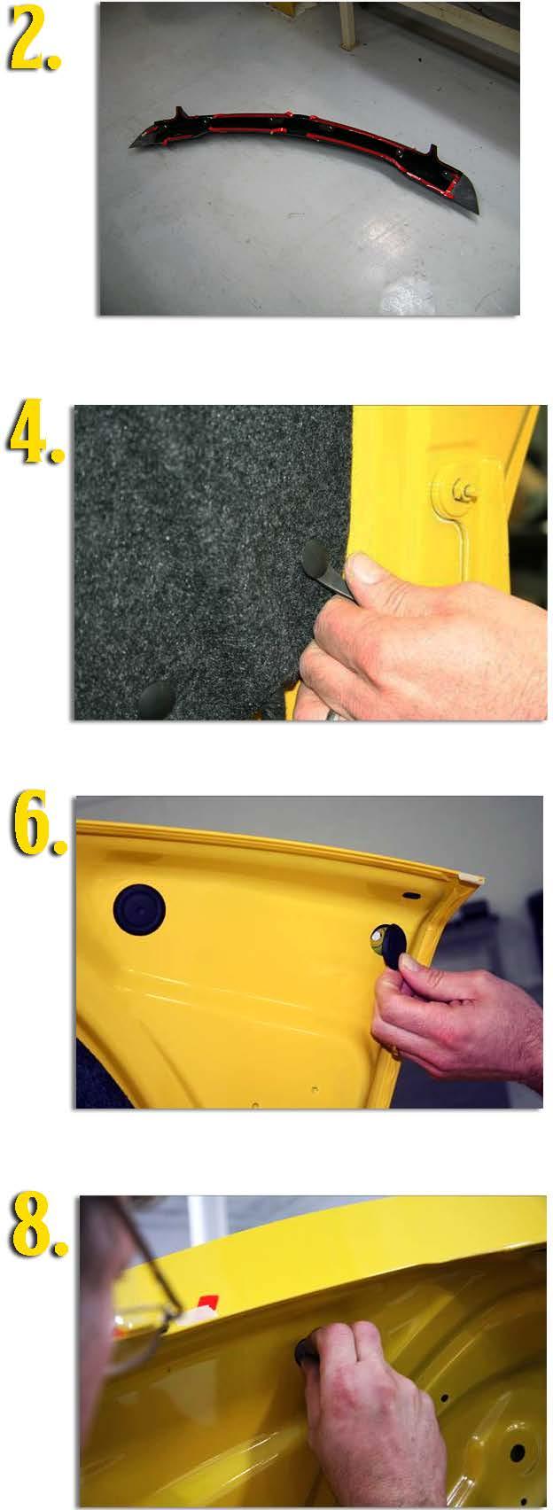
1 Side Rocker Installation Instructions Guidelines + Trial fit all parts prior to painting + Do not use the side rockers as an attachment point for tie downs + Every 3-6 months, make sure all fasteners are secure and check for any signs of detachment. + It is recommended that 2 people install this kit + During the painting process, make sure that the parts are not baked at more than 240 degrees (F). Included in kit: Otv-1 A Side Rocker LH B Side Rocker RH Oty-1 c XX Push Pin Oty-14 D N/A Double Sided Tape E N/A Adhesion Promoter Qty-2 Qty-2 Tools Required + 3/8" drill + 9.5mm or 3/8" drill bit + T20 Torx screwdriver Installation Instructions-Vehicle Prep and Part Prep Note: Prior to performing installation, make sure the vehicle surface and side rockers are at least 652 F (182C). Also, clean all contact areas of vehicle with 80/20 alcohol/water solution. Make sure all areas are dry and free of all dirt and contaminants. Note: With%" masking tape, tape off inside top tape locations with masking tape before having part painted. Remove masking tape before applying the 3M adhesive double sided tape. See Picture 1. 1) Wipe down inside tape flange with 80/20 alcohol/water mix. Allow to dry. 2) Apply supplied adhesion promoter to tape area. Allow to dry. 3) Apply double sided tape to the inside-top tape edge of the rockers leaving approximately lmm from the top edge. See picture 2. 4) Using masking tape, tape the leads to the face of the part. See Picture 3.

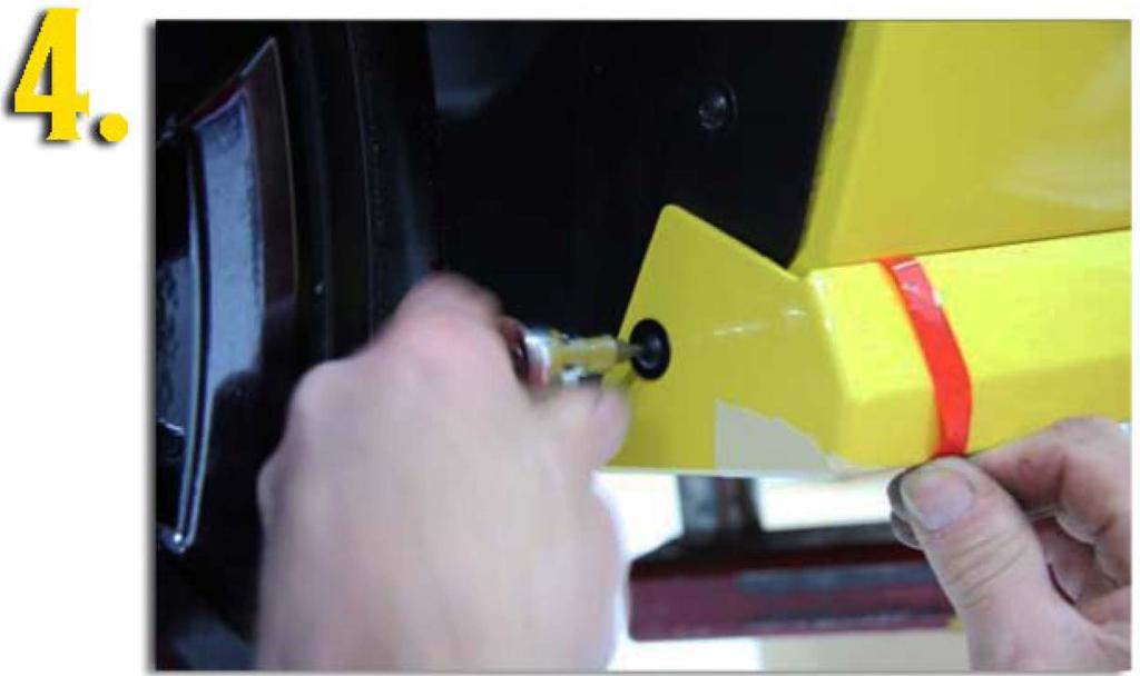
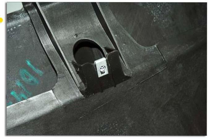
 Utilizing the T20 torx screw removed in step 5 above, insert through the hole in the new rocker and tighten. Do not torque at this time. See picture 4.")
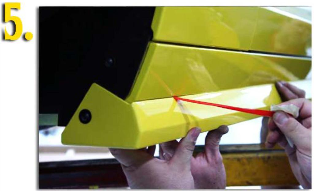
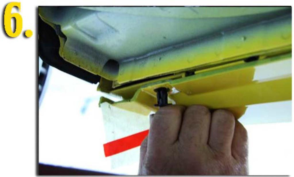
2 5) Inside both front wheel wells (rear of the opening), remove the lower T20 torx screws that attach the wheel liner to the stock rocker. These screws will be reused in the installation process of the new rocker. Installation Instructions-Side Rockers to Vehicle 1) Take the left hand side rocker and put in position on vehicle (2 people required). 2) Utilizing the T20 torx screw removed in step 5 above, insert through the hole in the new rocker and tighten. Do not torque at this time. See picture 4. 3) Make sure that the Havoc rocker is sitting flush against the bottom of the OEM rocker and tight along the top edge of the OEM rocker. 4) Starting at the front of the vehicle, slowly pull the tape lead towards the rear of the vehicle applying pressure to the Havoc rocker. See Picture 5. 5) Once the tape has been removed, make sure the fit is tight and secure to the OEM rocker. 6) Using a 9.5mm or 3/8" drill bit, drill 7 (equally spaced) holes using the Havoc rocker as the drill template. NOTE: It is recommended that you insert a push-pin after each hole that you drill. See Picture 6. 7) When complete, check that all fasteners are tight and secure. 8) Follow the same steps for the right hand rocker. 9) Let vehicle sit for 12 hours before driving to allow for tape to properly cure and adhere to the paint surf ace. [
3


4 Rear Spoiler Installation Instructions Guidelines + Trial fit all parts prior to painting + Take note of tape lengths during installation. It is recommended that you visit the website above, for the color visual for tape placement. + Do not use the rear spoiler to push or pull objects + Do not use the rear spoiler as an attachment point for tie downs + Refer to your city and state laws for use of on-road spoilers + Every 3-6 months, make sure all fasteners are secure and check for any signs of detachment. + It is recommended that 2 people install this kit + During the painting process, make sure that the parts are not baked at more than 240 degrees (F). Included in kit: A Rear Spoiler Qty-1 B RN Neoprene Washer Qty-6 Qtyc N/A Double Sided Tape 12 D XX Adhesion Promoter Qty-1 Tools Required + 1 OMM Deep Well Socket + Push Pin Removing Tool + lomm Drill Bit (if necessary, see note below) Installation Instructions-Vehicle Prep and Part Prep (Cars with 0 EM spoiler) Note: Prior to performing installation, make sure vehicle surface and rear spoiler are at least 65 2 F (18 2 C). Also, clean all contact areas of vehicle with 80/20 alcohol/water solution. Make sure all areas are dry and free of all dirt and contaminants.
5 Note: With %" masking tape, tape off inside top, bottom and side tape locations with masking tape before having part painted. Remove masking tape before applying the 3M adhesive double sided tape. See Picture 1. 1) Wipe down inside tape flange with 80/20 alcohol/water mix. Allow to dry. 2) Apply supplied adhesion promoter to tape area. Allow to dry. 3) Apply pieces of tape to the inside upper and lower spoiler sections and to the spoiler canards leaving lmm from the outer edge of the part. See picture 1and2 for tape placement. 4) Using masking tape, tape the leads to the face of the part. See Picture 3. 5) Remove the deck lid liner by removing the 11 pushpins located on the underside of the lid. Feed the emergency trunk release tag through the slot in the liner. Place the liner in a safe location away from the vehicle. See picture 3. 6) Remove the trunk latch cover by pulling outboard on the plastic housing. See picture 4. 7) Remove the (4) plugs from the four outboard holes (2 on each side). See Picture 5. 8) Remove the (6) M6 bolts holding the OEM spoiler in position making sure to remove the pushpin locator. 9) Add a piece of tape (3M #481 Preservation Sealing Tape is recommended) over the locator hole in the deck lid. This hole will not be used in the assembly process of the new spoiler. 1 O) Clean the deck lid surface. (Refer to preparation notes above) Note: Skip steps 7-9 for cars without an OEM spoiler. Installation Instructions-Rear Spoiler to Vehicle 1) Take the (6) neoprene washers (B), and insert them onto the spoiler studs. 2) Take the spoiler and feed the studs into the existing holes making sure the spoiler is sitting flush to the deck lid surface. Some manipulation of the studs through the holes may be required. See Picture 6. 3) Starting in the center, tighten left to right moving outboard. Tighten all 6 nuts (used from OEM spoiler). Do not torque to spec at this point. See Picture 7. 4) Starting at the center-front of the spoiler, pull tape leads outboard applying light pressure. Use the same steps for the next tape lead (front two outer pieces). See Picture 8. 5) Starting at the center-rear of the spoiler, pull tape leads outboard applying light pressure. Do the same process for the tape leads on the lower canards. See Picture 9. 6) Apply 35 lbs pressure to the entire spoiler making sure it is in full contact with the deck lid. 7) Tighten all 6 nuts to 26 in/lbs. 8) Install deck lid liner by reversing the steps of the removal process. 9) Let vehicle sit for 12 hours before driving to allow for tape to properly cure and adhere to the paint surf ace.
6 ***Note*** Due to the OEM variation in hole spacing, it may be required to open up the holes with a lomm drill bit. Be sure to add a rust inhibitor around the exposed metal. For cars without an OEM spoiler, complete the following steps before installing spoiler. 1) Follow the instructions on the template included in kit. 2) Apply supplied rust inhibitor to drilled holes 3) Continue to step 1 in the "Installation Instructions-Rear Spoiler to Vehicle" section above.
7
.")
8 Rear Diffuser Installation Instructions Guidelines Trial fit all parts prior to painting Do not use the diffuser as an attachment point for tie downs Every 3-6 months, make sure all fasteners are secure and check for any signs of detachment. It is recommended that 2 people install this kit During the painting process, make sure that the parts are not baked at more than 240 degrees (F). It is best to remove the 2 rear tire/wheel assemblies for this installation Included in kit: Letter Part Number A B c PA D N/A E N/A F XX G XX Description Diffuser-Outer Diffuser-Inner Clip 8mm U-Clip Double Sided Tape Adhesion Promoter 8mm Push Pin Quantity Tools Required Push Pin Puller 7mm socket #2 Screwdriver 9mm or 5/16" drill bit Installation Instructions-Vehicle Prep and Part Prep Note: Prior to performing installation, make sure the vehicle surf ace and diffuser are at least 65Q F (18QC). Also, clean all contact areas of vehicle with 80/20 alcohol/water solution. Make sure all areas are dry and free of all dirt and contaminants. Note: With %" masking tape, tape off the two outside tab locations with masking tape before having part painted. Remove masking tape before applying the 3M adhesive double sided tape. See Picture 1. 1) Wipe down outside tabs with 80/20 alcohol/water mix. Allow to dry.
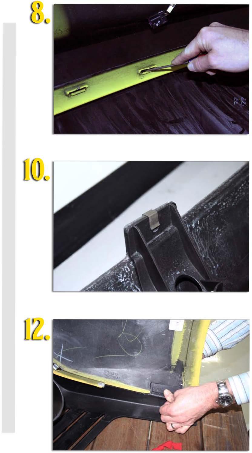
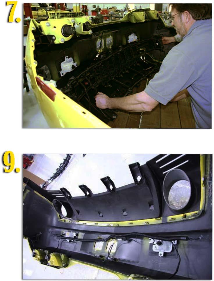
9 2) Apply supplied adhesion promoter to tape area. Allow to dry. 3) Apply double sided tape to the outside tabs of the diffuser covering entire surface. 2 pieces of tape are supplied with your kit. See picture 2. 4) Open trunk lid and remove both plastic comer covers by removing 3 push pins on both sides. See picture 3. 5) Unplug both tail lamp harness connections. 6) Remove 4 fasteners holding each of the rear of the wheel well liners. (Rear 4 fasteners only) (1) 7mm head bolt and 3 screws. See picture 4. 7) Taking caution not to flex the fascia, grab the front of the rear fascia and pull outward to release the tabs. See picture 5. 8) Using two people, pull the rear fascia from the rear and remove. Place the fascia on a soft surface as installation of the new diffuser will be done off car. See Picture 6. 9) From the inside of the fascia, remove the honeycomb EA bracket attached to the OEM diffuser. This can be accomplished by leaving the wire harness attached to the bracket, but unplugging all connections to the lights. You will also need to remove the 4 bolts holding the bracket to the OEM diffuser. See picture 7. 10) Remove the OEM diffuser by sliding the tabs through the slots in the fascia and remove from the front. See Picture 8. 11) Remove the 4 clip nuts from the OEM diffuser as they will be used again in the installation process. Installation Instructions-Rear Diffuser to Fascia 1) Take the inner section (B) of the diffuser and insert the ( 4) tabs through the outer section (A) of the Havoc diffuser. Install 4 (C) clips on the back of the diffuser making sure the clips fit tight against wall of the outer section. If the clips are not flush, trim a small amount of length off the tabs. 2) Take the Havoc rear diffuser and feed tabs through the slots in the fascia (opposite of removal process). Insert the 16 clips (C) over each of the tabs making sure that the angled section of the clip sits flush with the fascia. See picture 9. 3) Using clip (D), match up the 4 forward tabs and slide over the top of both, mating the inner and outer sections together. See picture 10. 4) Insert the 4 clip nuts removed from the OEM diffuser and attach to the 4 stand off's on the new diffuser. See Picture 11. 5) Install the honeycomb EA bracket reversing the removal process above. Make sure the 4 bolts removed in step 9 of the "Vehicle Prep and Part Prep", get reinstalled to the new diffuser. Make sure all harnesses are properly secured to the lights. 6) Take the 2 taped sections and position so they are sitting inside the lower lip of the rear fascia. Remove the tape backing and firmly press so the tape adheres to the fascia. 35 lbs of pressure is recommended. See picture 12. 7) Dependent upon on driving conditions in your area, it is advised that you drill a hole through the upstanding flange on the front part of the diffuser, as well as
 through the wheel liner and into the flange.")
 Install the fascia reversing the removal instructions.")
10 through the wheel liner and connect using the supplied push pin. Insert the pushpin (G) through the wheel liner and into the flange. NOTE: Holding the fascia in car position, make sure everything lines up before re-installing on the vehicle. 8) Install the fascia reversing the removal instructions. 9) Let vehicle sit for 12 hours before driving to allow for tape to properly cure and adhere to the paint surface.
11 ([


12 Front Chin Spoiler Installation Instructions Guidelines + Trial fit all parts prior to installation + The front Chin Spoiler only fits V8 cars. It will not fit any 6 cylinder fascias. + Do not use the front chin spoiler to push or pull objects + Do not use the front chin spoiler as an attachment point for tie downs + Every 3-6 months, make sure all fasteners are secure and check for any signs of detachment. + 2 people are necessary to install this kit + Use caution driving onto driveway aprons, speed bumps and severe inclines/declines as the chin spoiler is positioned lower than stock. + During the painting process, make sure that the parts are not baked at more than 240 degrees (F). Included in kit: A Chin Spoiler Qty-1 B C Z-Bracket Outer Qty-2 c C Z-Bracket Inner Oty-2 D N/A Double Sided Tape Otv-4 E N/A Adhesion Promoter Otv-1 Tools Required + lomm Deep Well Socket + Flat Head Screwdriver Installation Instructions-Vehicle Prep and Part Prep Note: Prior to performing installation, make sure the vehicle surface and chin spoiler are at least 652 F (182C). Also, clean all contact areas of vehicle with 80/20 alcohol/water solution. Make sure all areas are dry and free of all dirt and contaminants. Note: With %" masking tape, tape off inside top and side tape locations with masking tape before having part painted. Remove masking tape before applying the 3M adhesive double sided tape. See Picture 1. 1) Wipe down inside tape flange with 80/20 alcohol/water mix. Allow to dry.
13 2) Apply supplied adhesion promoter to tape area. Allow to dry. 3) Apply tape to inside upper (2 pieces from center) and side locations (1 piece on each side) of chin spoiler leaving lmm from the outer edge of the part. See picture 2. 4) Using masking tape, tape the leads to the face of the part. See Picture 3. 5) Remove factory chin strap by removing the (18) fasteners holding it to the bottom of the front fascia. 6) Remove the (2) center M6 bolts that secure the fascia to the sub-frame. Installation Instructions-Chin Spoiler to Vehicle 1) Take the chin spoiler and put in position on vehicle (2 people required). 2) Utilizing the (2) M6 bolts removed from the center of the fascia, insert them into the stand off's on the chin spoiler. See picture 4. Note: You will not be able to get the bolt through the hole in the bottom of the chin spoiler due to the washer diameter. Put the socket through the chin hole first, and manually feed the bolt inside the stand off. 3) Utilizing the supplied Z-brackets, take (2) brackets (B) and install on both outboard edges of chin spoiler using (4) screws and nuts removed from chin strap. See picture 5. 4) Utilizing the supplied Z-brackets, take (4) brackets (C) and install on the inboard locations of chin spoiler using (8) screws and nuts removed from the chin strap. See picture 6. 5) Starting at the center (2 people required), pull the tape leads parallel to the top edge of the chin spoiler. While pulling, apply pressure to the top edge making sure the tape is securely adhering to the front fascia. Apply approximately 30 PSI to the taped area. See Picture 7. 6) Do the same process for the tape on the outboard side of the chin spoiler. See Picture 8. 7) Check that all fasteners are tight and secure. 8) Let vehicle sit for 6 hours before driving to allow for tape to properly adhere to the paint surface.


14 -- Add style with first-class body kits and ground effects we offer.
Rear Spoiler Installation Instructions
 Rear Spoiler Installation Instructions Guidelines For complete instructions in color, please go to our website at www.ivsauto.com If your Camaro did not come with an OEM spoiler, IVS kit # 9006-1013-01
Ground Effects, P/N: (V6), (V8)
, (V8)") , P/N: 92248596 (V6), 92248560 (V8) 3. Open trunk and remove 3 scrivets per side. Retain. Remove LH and RH tail lamp access cover. Retain. Refer to Figure 1. NOTE: Installation is made easier with the
, P/N: 92248596 (V6), 92248560 (V8) 3. Open trunk and remove 3 scrivets per side. Retain. Remove LH and RH tail lamp access cover. Retain. Refer to Figure 1. NOTE: Installation is made easier with the
TESLA MODEL S REAR UNDER SPOILER & DIFFUSER SYSTEM
 TESLA MODEL S Thank you for purchasing your Unplugged Performance Rear Under Spoiler & Diffuser System for the Tesla Model S! Please read this manual carefully prior to installation. REAR UNDER SPOILER
GENUINE PARTS INSTALLATION INSTRUCTIONS
 GENUINE PARTS INSTALLATION INSTRUCTIONS DESCRIPTION: APPLICATION: PART NUMBER: KIT-CARBON FIBER REAR SPOILER INFINITI Q50 T99J1 J5000 KIT CONTENTS: Item A B C D Qty. 1 4 1 1 Part Description Spoiler Assembly
Rev TOOLS & MATERIALS REQUIRED QTY 3D PART NO. DESCRIPTION
 Rev. 04-10 QTY 3D PART NO. DESCRIPTION 1 691609 FRONT BUMPER REPLACEMENT 1 691610 RIGHT SIDE SKIRT 1 691611 LEFT SIDE SKIRT 1 691612 REAR LOWER SKIRT 4 3M 94 3M ADHESION PROMOTER 16 #8 X ¾ SELF DRILLING
Preparation Part Number: PT Kit Contents Item # Quantity Reqd. Description 1 1 Rear Spoiler 2 1 Hardware Kit. Hardware Bag Contents
 Preparation Part Number: PT478-11170-09 Kit Contents 1 1 Rear Spoiler 2 1 Hardware Kit Hardware Bag Contents 1 4 M5 Nut 2 4 Clip 3 4 Hole Plug Additional Items Required For Installation 1 1 Outer Drill
Lingenfelter Signature Series Camaro SS Rear Valance
 Lingenfelter Signature Series 2010-2012 Camaro SS Rear Valance PN: L850161410 Lingenfelter Performance Engineering 1557 Winchester Road Decatur, IN 46733 (260) 724-2552 (260) 724-0422 fax www.lingenfelter.com
INSTALLATION INSTRUCTIONS
 INSTALLATION INSTRUCTIONS Document# 19-0038 2004+ Lotus Elise (Series 2) Rear Clamshell Removal Kit Safely support the vehicle. This is a two-person job. Allow 1 to 2 hours for initial disassembly. Have
QTY 3D PART NO. DESCRIPTION
 QTY 3D PART NO. DESCRIPTION 1 691032 V6 FRONT AIR DAM 1 691023 SIDE SKIRT RIGHT 1 691024 SIDE SKIRT LEFT 1 691566 V6 DUAL EXHAUST REAR LOWER SKIRT- 8 3M 94 3M ADHESION PROMOTER 24 #8 X ¾ SELF DRILLING
TOYOTA COROLLA HATCHBACK REAR SPOILER Preparation
 Preparation Part Number: PT29A-12195-XX Kit Contents 1 1 Rear Spoiler 2 2 Hardware Bag Hardware Bag Contents 1 2 M6 Assembly Nuts 2 2 Grommet Inserts 3 1 Hole Plug Additional Items Required For Installation
INSTALLATION GUIDE PREMIUM FRONT BUMPER FOR RAM AEV30304AA Last Updated: 09/18/17
 AEV30304AA Last Updated: 09/18/17 PREMIUM FRONT BUMPER FOR RAM 1500 INSTALLATION GUIDE PLEASE READ BEFORE YOU START To guarantee a quality installation, we recommend reading these instructions thoroughly
INSTALLATION INSTRUCTIONS
 INSTALLATION INSTRUCTIONS Accessory Application Publications No. SPOILER (LOW) 2005 ACCORD 4-DOOR AII 27503 Issue Date AUG 2004 PARTS LIST Trunk spoiler Right trunk spring (marked green) Left trunk spring
Ford Mustang Rear Decklid Spoiler Kit. Installation Instructions
 Ford Mustang Rear Decklid Spoiler Kit Application: 2005-09 Ford Mustang Installation Instructions Before installing your ROUSH Performance Product(s), read through the entire installation procedure and
Expedition Front Bumper Instructions
 Expedition Front Bumper Instructions QTY 3D PN. FCS PART NUMBER DESCRIPTION 1 691256 A 8 E X D - 1 7 B 635-AAPLN FRONT BUMPER REPLACEMENT HARDWARE SUPPLIED 10 SELF TAPING SCREWS -10 for Front Bumper PLASTIC
INSTALLATION INSTRUCTIONS
 INSTALLATION INSTRUCTIONS Accessory Application 2012 CIVIC 4-DOOR Publications No. AII 45625-46263 Issue Date MAY 2011 PARTS LIST Trunk spoiler Left trunk spring (marked yellow) Template 4 Clip grommets
2015+ Mustang Rear Valance Installation Instructions P/N: (R F953) (R F953BS)
 (R F953BS)") 2015+ Mustang Rear Valance Installation Instructions P/N: 421894 (R1315-17F953) 421919 (R1315-17F953BS) 39555 Schoolcraft Rd, Plymouth MI, 48170 800.59.ROUSH 2015+ Mustang Rear Valance Kit Installation
2015+ Mustang Rear Valance Installation Instructions P/N: 421894 (R1315-17F953) 421919 (R1315-17F953BS) 39555 Schoolcraft Rd, Plymouth MI, 48170 800.59.ROUSH 2015+ Mustang Rear Valance Kit Installation
MUSTANG TIGER CAGE INSTRUCTIONS MANUAL PAGE 1
 2005-2011 MUSTANG TIGER CAGE INSTRUCTIONS MANUAL PAGE 1 Thank you for purchasing our 2005-2011 Mustang Tiger Cage. Please read through all of the instructions first and then start installing the kit. We
Double-check to ensure that all of the parts are included in your shipment. Please immediately contact 3dCarbon if you are missing any part.
 5 Pc. Kit Includes QTY 3D PN. DESCRIPTION 1 691815 CRUZE FRONT AIR DAM POLYURETHANE PRE-PRIMERED 1 691816 CRUZE SIDE SKIRT RH POLYURETHANE PRE-PRIMERED 1 691819 CRUZE SIDE SKIRT LH POLYURETHANE PRE-PRIMERED
HITCH INSTALLATION INSTRUCTIONS TESLA MODEL 3 PACKAGE: RACK Present MODEL/TRIM: MAKE: YEARS: 2 HOURS TOOLS REQUIRED: PARTS SUPPLIED:
 HITCH INSTALLATION INSTRUCTIONS MAKE: TESLA YEARS: 2017 Present MODEL/TRIM: MODEL 3 WEIGHT CAPACITY TRAILER TONGUE N/A LBS. 200 LBS. PACKAGE: RACK INSTALLATION TIME: 2 HOURS DO NOT EXCEED VEHICLE MANUFACTURE
INSTALLATION INSTRUCTIONS
 INSTALLATION INSTRUCTIONS Accessory Application Publications No. SPOILER (LOW) 2011 CIVIC 4-DOOR All 44416 Issue Date AUG 2010 PARTS LIST Trunk spoiler Right trunk spring (marked red) Left trunk spring
GENUINE PARTS INSTALLATION INSTRUCTIONS
 GENUINE PARTS INSTALLATION INSTRUCTIONS 1. 2. 3. 4. DESCRIPTION: APPLICATION: PART NUMBER: KIT CONTENTS: Fog Lamp Kit Versa Note (SV Only) 999L1 4Z000 - Fog Lamp Kit Item QTY Description Service Part Number
QTY 3D PART NO. FORD SERVICE PN DESCRIPTION VAA6Z A FIESTA 5 DOOR (4) PC. KIT
 PC. KIT") Rev. 08-4 - 2010 QTY 3D PART NO. FORD SERVICE PN DESCRIPTION 1 691620 VAA6Z-5820049-A 2011- FIESTA 5 DOOR (4) PC. KIT HARDWARE SUPPLIED 12 #8 X ¾ SELF DRILLING SCREWS 220 / 18.5 3M VHB DOUBLE FACE TAPE
Rev. 08-4 - 2010 QTY 3D PART NO. FORD SERVICE PN DESCRIPTION 1 691620 VAA6Z-5820049-A 2011- FIESTA 5 DOOR (4) PC. KIT HARDWARE SUPPLIED 12 #8 X ¾ SELF DRILLING SCREWS 220 / 18.5 3M VHB DOUBLE FACE TAPE
ASSEMBLY & INSTALLATION INSTRUCTIONS
 ASSEMBLY & INSTALLATION INSTRUCTIONS VEHICLE MOUNT KIT 99101087 AND VEHICLE CENTER MEMBER For 26 Series: 99100890 TO FIT 2009 & Later FORD F150 4x4 (without EcoBoost V6) 2011 & Later FORD F150 4x4 (with
TOYOTA HIGHLANDER RUNNING BOARD HIGHLANDER HV Preparation
 Preparation Part Number: PT738-48080 Kit Contents Item # Quantity Reqd. Description 1 1 Driver Side Running Board 2 1 Passenger Side Running Board 3 4 /Middle Mount Bracket 4 2 Rear Mount Bracket 5 2 Rear
TESLA MODEL S REFRESH FRONT FASCIA INSTALLATION MANUAL FIGURE 1. Unplugged Performance 3523 Jack Northrop Ave, Hawthorne, CA 90250
 INSTALLATION MANUAL TESLA MODEL S PARTS QUANTITY INCLUDES FRONT FASCIA 1 PIECE V-STRIPE PANEL 1 PIECE HARDWARE KIT 1 SET PDC SENSOR HOLDERS 4 / 6 PIECES HOOD RELEASE KIT 1 KIT REFRESH FRONT FASCIA PLEASE
INSTALLATION INSTRUCTIONS
 INSTALLATION INSTRUCTIONS Accessory Application Publications No. Bll 37371 SPOILER 2008 TL Issue Date JUN 2007 PARTS LIST Trunk spoiler Left trunk spring (marked yellow) Template A TOOLS AND SUPPLIES REQUIRED
GENUINE PARTS INSTALLATION INSTRUCTIONS
 GENUINE PARTS INSTALLATION INSTRUCTIONS 1. 2. 3. 4. DESCRIPTION: APPLICATION: PART NUMBER: KIT CONTENTS: Accent light Kit Versa Note 999F3 4Z000 - Accent Lighting Kit. 999Q9 AY000 - Accessory Service Connector
HARD FOLDING TONNEAU COVER INSTALLATION GUIDE
 HARD FOLDING TONNEAU COVER INSTALLATION GUIDE GUIDE FOR FOLD-A-COVER FD3701, FD3702 TRUCK MODEL(S): 1998-2007 FORD F-150 NOTES TO INSTALLER: 70 F when installing. surface. Some trimming of bed liner may
INSTALLATION INSTRUCTIONS
 INSTALLATION INSTRUCTIONS Accessory Application Publications No. SPOILER (LOW) CIVIC 4-DOOR All 30833 Issue Date SEP 2005 PARTS LIST Trunk spoiler Right trunk spring (marked red) Left trunk spring (marked
IMPORTANT: PLEASE RETAIN THIS INSTRUCTION MANUAL FOR FUTURE REFERENCE
 IMPORTANT: PLEASE RETAIN THIS INSTRUCTION MANUAL FOR FUTURE REFERENCE 2009 Toyota RAV-4 Stainless Steel Mesh Grilles L 30 G8P Fine Mesh Part #30-002-09 Quantity Description Part No. Upper Mesh Grille (includes):
SS1066HF Jeep JK Wrangler Left Hand Drive CRDI4 2.8Litre-I4 Diesel Engine and EGHV6 3.8Litre V6 Gasoline Engine
 SS1066HF Jeep JK Wrangler Left Hand Drive CRDI4 2.8Litre-I4 Diesel Engine and EGHV6 3.8Litre V6 Gasoline Engine Installation Guide Safari SS1066HF Page - 1 of 12 6/10/2009 ITEM PART NO DESCRIPTION QTY
HiBoy Maverick/Commander Doors Part # HiBoy4 Maverick/Commander Doors Black
 Racing 3191 N Washington St. Suite 2 Chandler, AZ 85225 1 (800) 708-9803 http://www.racing.com HiBoy Maverick/Commander Doors Part # 07-2001 HiBoy4 Maverick/Commander Doors Black Congratulations on your
Aggressive Chin Spoiler CDC#
 Note: 2005-2009 Aggressive Chin Spoiler CDC# 110021 Read installation instructions before starting and test fit component before painting. Chin Spoiler is a molded Urethane part. To ensure the quality
QTY 3D PN. FCS PART NUMBER DESCRIPTION
 QTY 3D PN. FCS PART NUMBER DESCRIPTION 1 691544 A8FOC-17B635-APL FOCUS FRONT AIR DAM 1 691549 A8FOC-17E957-APL FOCUS REAR LOWER 1 691548 A8FOC-10154-APL FOCUS RIGHT SIDE SKIRT 1 691547 A8FOC-10155-APL
GENUINE PARTS INSTALLATION INSTRUCTIONS
 GENUINE PARTS INSTALLATION INSTRUCTIONS 1. 2. 3. 4. DESCRIPTION: Front Protector Kit APPLICATION: G Sedan Sports PART NUMBER: K6010-1NH** (XX Designates color) KIT CONTENTS: Item Qty. Description Part
INSTALLATION INSTRUCTIONS
 INSTALLATION INSTRUCTIONS Accessory Application Publications No. SPOILER (DECK LID) ACCORD 4-DOOR AII 24063 Issue Date AUG 2002 PARTS LIST Trunk spoiler Right trunk spring (marked green) Left trunk spring
2018+ Mustang Lower Grill and Chin Spoiler Kits Installation Instructions P/N: (R K945) P/N: (R F775)
 P/N: (R F775)") 2018+ Mustang Lower Grill and Chin Spoiler Kits Installation Instructions P/N: 422081 (R1318-17K945) P/N: 422082 (R1318-17F775) 39555 Schoolcraft Rd, Plymouth MI, 48170 800.59.ROUSH 2018+ Mustang Lower
2018+ Mustang Lower Grill and Chin Spoiler Kits Installation Instructions P/N: 422081 (R1318-17K945) P/N: 422082 (R1318-17F775) 39555 Schoolcraft Rd, Plymouth MI, 48170 800.59.ROUSH 2018+ Mustang Lower
JK8 Body Kit KIT CONTENTS 1 K
 JK8 Body Kit KIT CONTENTS A B C 1 K6861352 D E G F H 2 K6861352 I M N J K L O P Q R S 3 K6861352 T U V W X Y CALL OUT PART NUMBER DESCRIPTION QUANTITY A P5156021 HARDTOP 1 B P5155997 BULKHEAD 1 C 1PH98/9TZZAE
Mustang V6 Shaker 99-04* Components Check List:
 Mustang V6 Shaker 99-04* Components Check List: *03 Model requires new hood CDC Inspected Installer Check Quantity Descriptions 1- Hood Appliqué 1- Aluminum Shaker Scoop 1- Lower Air Box w/drain tube fittings
2015 Mustang Fastback Rear Spoiler Installation Instructions P/N:
 Installation Instructions P/N: 421883 421884 421885 421886 421887 421888 421889 421890 421891 421892 421893 39555 Schoolcraft Rd, Plymouth MI, 48170 800.59.ROUSH 2015 Mustang Fastback Rear Spoiler Installation
Conflicts NOTE: XLE, LE, AND SE MODELS
 TOYOTA SIENNA 2011- REARSIGHT Part Number: 00016-00085 Accessory Code: MC9 Conflicts NOTE: XLE, LE, AND SE MODELS KIT CONTENTS ITEM QTY DESCRIPTION 1 1 MIRROR/MONITOR 2 1 REAR CAMERA ASSEMBLY 3 1 CAMERA
GENUINE PARTS INSTALLATION INSTRUCTIONS
 GENUINE PARTS INSTALLATION INSTRUCTIONS 1. 2. 3. 4. DESCRIPTION: Accent light Kit APPLICATION: Versa (2012) PART NUMBER: 999F3 AW008 - Universal Accent Lighting Kit. KIT CONTENTS: Item QTY Description
GENUINE PARTS INSTALLATION INSTRUCTIONS
 GENUINE PARTS INSTALLATION INSTRUCTIONS 1. 2. 3. 4. DESCRIPTION: Accent light Kit APPLICATION: R42H (2011) PART NUMBER: 999F3 AW000 - Universal Accent Lighting Kit. KIT CONTENTS: Item QTY Description Service
Mustang CLASSIC LIGHT BAR INSTALLATION INSTRUCTIONS CDC #
 1990-1993 Mustang CLASSIC LIGHT BAR INSTALLATION INSTRUCTIONS CDC # 101000 Kit Components: 1 Light Bar 4 Bolts ( 5 / 16-18 x 2.5 ) #182010 4 Washer #182005 4 Shims #182009 2 Dark Blue Connectors #182004
POLY TIP-DOWN WINDSHIELD KIT
 POLY TIP-DOWN WINDSHIELD KIT P/N 2881919 APPLICATION Verify accessory fitment at Polaris.com. BEFORE YOU BEGIN Read these instructions and check to be sure all parts and tools are accounted for. Please
REV READ BEFORE INSTALLATION OF KIT:
 REV. 05-08 QTY 3D PN. FCS PART NUMBER DESCRIPTION 1 691509 A7EDG-7820049-AAPLN EDGE BODY KIT- V6 B PCS & EXH TIPS 1 691256 A 7 E D G - 7 8 20049-BAPLN EDGE BODY KIT- V6 8PCS & EXH TIPS W/HITCH 1 691501
INSTALLATION INSTRUCTIONS
 INSTALLATION INSTRUCTIONS Accessory REAR SPOILER Application 2011 CR-Z MUGEN Publications No. AII 45919 Issue Date APRIL 2011 PARTS LIST Right wing bracket Rear wing Left wing bracket Right wing base Right
LPE C5 Battery Relocation Kit
 LPE C5 Battery Relocation Kit The LPE C5 Corvette battery relocation kit improves vehicle weight distribution by moving weight to the rear of the vehicle. The improved weight distribution increases traction
QTY 3D PN. FCS PART NUMBER DESCRIPTION
 Rev.05-08 QTY 3D PN. FCS PART NUMBER DESCRIPTION 1 691224 A6ZEP-17B635-AAPLN MKZ FRONT AIR DAM 1 691202 A6ZEP-5410154-AAPLN MKZ SIDE SKIRT RH 1 691203 A6ZEP-5410155-AAPLN MKZ SIDE SKIRT LH 1 691225 A6ZEP-17E957-AAPLN
2005+ Roll Bar (Mm5RB-20.1 to -20.6) Recommended Center punch 1/8" pilot drill 1-3/4" Hole saw 2" Hole saw
 Recommended Center punch 1/8 pilot drill 1-3/4 Hole saw 2 Hole saw") 3430 Sacramento Dr., Unit D San Luis Obispo, CA 93401 Telephone: 805/544-8748 Fax: 805/544-8645 www.maximummotorsports.com 2005+ Roll Bar (Mm5RB-20.1 to -20.6) Recommended Center punch 1/8" pilot drill
3430 Sacramento Dr., Unit D San Luis Obispo, CA 93401 Telephone: 805/544-8748 Fax: 805/544-8645 www.maximummotorsports.com 2005+ Roll Bar (Mm5RB-20.1 to -20.6) Recommended Center punch 1/8" pilot drill
IMPORTANT: PLEASE KEEP THIS INSTRUCTION MANUAL FOR FUTURE REFERENCE! 2015 Nissan Murano. Upper and Lower Overlay Mesh Grilles
 IMPORTANT: PLEASE KEEP THIS INSTRUCTION MANUAL FOR FUTURE REFERENCE! 2015 Nissan Murano Upper and Lower Overlay Mesh Grilles Upper Chrome Mesh Part #1318-010U-15 / Lower Chrome Mesh Part #1318-010L-15
Fog Lamp Instructions
 Fog Lamp Instructions 2011+ Ford Super Duty Congratulations on your purchase of a high quality PUTCO product. Should you need any application or technical assistance feel free to call us at: 1-800-247-3974
INSTALLATION INSTRUCTIONS
 INSTALLATION INSTRUCTIONS Accessory S Application 2011 PILOT Publications No. AII 43298 Issue Date MARCH 2010 PARTS LIST Back-up Sensor Attachment Kit P/N 08V67-SZA-100A Back-up sensor harness Fuse label
CENTER BELT SYSTEM INSTALLATION INSTRUCTIONS CARCG121220
 CENTER BELT SYSTEM INSTALLATION INSTRUCTIONS 2013+ DODGE CHARGER Distributed by CARCG121220 Important Notice: Read all instructions before starting the installation of the seat. Before drilling or installing
Remote engine start INSTALLATION INSTRUCTIONS
 GENUINE Remote engine start INSTALLATION INSTRUCTIONS Thank you for purchasing a genuine Mazda accessory. Before removal and installation, be sure to thoroughly read these instructions. Please read the
GENUINE PARTS INSTALLATION INSTRUCTIONS
 GENUINE PARTS INSTALLATION INSTRUCTIONS 1. DESCRIPTION: Trailer Tow mirror kit (with power and heated) Trailer Tow mirror kit (with power, heated, and memory) 2. APPLICATION: 04 Titan, Armada, QX56 LE,
GENUINE PARTS INSTALLATION INSTRUCTIONS
 GENUINE PARTS INSTALLATION INSTRUCTIONS 1. 2. 3. 4. DESCRIPTION: Security Light Kit APPLICATION: Altima Coupe and Sedan (2011+) PART NUMBER: 999F4 AX008 - Universal Security Lighting Kit. KIT CONTENTS:
INSTALLATION INSTRUCTIONS
 INSTALLATION INSTRUCTIONS Accessory SPOILER (LOW) P/N 08F10-TA0-100 Application 2009 ACCORD 4-DOOR Publications No. AII 40062 Issue Date JULY 2008 PARTS LIST Trunk spoiler Right trunk spring (marked red)
M-9603-FST FOCUS ST COLD AIR INTAKE KIT INSTALLATION INSTRUCTIONS
 M-9603-FST Please visit www.fordracingparts.com for the most current instruction information.!!! PLEASE READ ALL OF THE FOLLOWING INSTRUCTIONS CAREFULLY PRIOR TO INSTALLATION. AT ANY TIME YOU DO NOT UNDERSTAND
CERTAIN 2005 MODEL YEAR FIVE HUNDRED, MONTEGO AND CERTAIN 2005 AND 2006 MODEL YEAR FREESTYLE VEHICLES DOOR LATCH WATER PROTECTION
 CERTAIN 2005 MODEL YEAR FIVE HUNDRED, MONTEGO AND CERTAIN 2005 AND 2006 MODEL YEAR FREESTYLE VEHICLES LATCH WATER PROTECTION ATTACHMENT III PAGE 1 OF 9 OVERVIEW Depending on vehicle and build date, this
M-5230-V6 Mustang V6 Dual Exhaust Kit INSTRUCTION SHEET
 Please contact the Techline for the most current instruction information (800) FORD788.!!! PLEASE READ THE FOLLOWING INSTRUCTIONS CAREFULLY PRIOR TO INSTALLATION!!! OVERVIEW: The use of a floor hoist is
2017 Current Ford Raptor Bump Stop Kit Installation Instructions
 2017 Current Ford Raptor Bump Stop Kit Installation Instructions PREPARATION 1. Disconnect the negative terminal on the battery. Park the vehicle on level ground and set the emergency brake. 2. We recommend
INSTALLATION INSTRUCTIONS
 INSTALLATION INSTRUCTIONS Accessory Application Publications No. Bll 27035-29095 2005 RL Issue Date MAY 2005 PARTS LIST Trunk spoiler Right support strut Left support strut 4 Washer-bolts 4 Adhesive seals
Barton Short Throw Shifter 11/12 V6, GT Mustang:
 Barton Short Throw Shifter 11/12 V6, GT Mustang: Tools Required: 10mm deep socket Socket wrench 10 extension for socket wrench Jack Jack stand Small piece of wood Small hook tool (recommended) *can be
INSTALLATION INSTRUCTIONS
 11485 YEARS: 2015-CURRENT Safety glasses should be worn at all times while installing this product. INSTALLATION INSTRUCTIONS MODEL: C300 MAKE: MERCEDES STYLE: SEDAN WARNING: NEVER EXCEED YOUR VEHICLE
INSTALLATION INSTRUCTIONS
 INSTALLATION INSTRUCTIONS Accessory Application Publications No. AII 27955 SIDE 2005 CIVIC SI Issue Date AUG 2004 PARTS LIST Left side under spoiler Right side under spoiler 6 Plates 8 Clips Template INSTALLATION
Carli Suspension Front Instructions
 Carli Suspension Front Instructions 94-08 DODGE 2500-3500 4X4 SUSPENSION SYSTEM Note: Prior to installation, carefully inspect the vehicle=s steering and drive train components. Be sure to check ball joints,
2011 Honda Accord Coupe Fine Mesh Grille
 IMPORTANT: PLEASE KEEP THIS INSTRUCTION MANUAL FOR FUTURE REFERENCE! TOOLS REQUIRED 2011 Honda Accord Coupe Fine Mesh Grille Replacement Upper / Lower Overlay Part #: Complete #1124-0102-11 / Black Ice
GENUINE REAR SPOILER
 GENUINE REAR SPOILER IMPORTANT POINTS IN PAINTING PART NAME: REAR SPOILER PART NUMBER: 0000-8Y-H50/GHK1 V4 920/G44B V4 920 VEHICLE: MAZDA6 1 PAINT AREAS SURFACE TREATMENT a : Paint same as body color b
GENUINE PARTS INSTALLATION INSTRUCTIONS
 GENUINE PARTS INSTALLATION INSTRUCTIONS 1. 2. 3. DESCRIPTION: APPLICATION: PART NUMBER: Accent light Kit Cube (MY2013+) 999F3 AW000 - Universal Accent Lighting Kit. 4. KIT CONTENTS: Item QTY Description
Please read thoroughly before starting installation and check that kit contents are complete.
 Rear Vision System Mirror Display 2013-Current Ram (Kit part number 1009-9518) Please read thoroughly before starting installation and check that kit contents are complete. Items Included in the Kit: Rear
VOLKSWAGEN AMAROK 3 PIECE HARD TONNEAU COVER INSTALLATION INSTRUCTIONS
 VOLKSWAGEN AMAROK 3 PIECE HARD TONNEAU COVER INSTALLATION INSTRUCTIONS Care Instructions: Clean Tonneau Cover with a mild detergent and water solution. Do not use abrasive cleaners or solvents. Place these
Item C& D Not Applicable C
 GENUINE PARTS INSTALLATION INSTRUCTIONS DESCRIPTION: APPLICATION: PART NUMBER(S) REQUIRED FOR INSTALLATION: KIT CONTENTS: LED Fog Lamp Upgrade Rogue Sport 999F1 V4001 A B Item C& D Not Applicable C D Do
INSTALLATION INSTRUCTIONS
 INSTALLATION INSTRUCTIONS Accessory Application Publications No. Bll 30250 UNDER SPOILER 2006 RSX Issue Date JULY 2005 PARTS LIST Rear under spoiler 5 Stepped bolts 2 Bolts 7 Flange nuts, 6 mm 3 Square
H15P. Toyota Hilux A-DECK Dual Cab
 Toyota Hilux A-DECK Dual Cab Page 1 of 14 Fitting Instructions Part Number H15 Toyota Hilux A-DECK Dual Cab 2015+ To suit Sports Bars Check contents of kit before commencing fitment and report any discrepancies
 INSTALLATION INSTRUCTIONS Accessory Application Publications No. AII 33173 UNDER 2007 ODYSSEY Issue Date JULY 2006 PART LIST Front under spoiler 5 Stepped bolts TOOLS AND SUPPLIES REQUIRED Phillips screwdriver
TOYOTA YARIS HATCHBACK INTERIOR LIGHT UPGRADE Preparation
 Preparation Part Number PTS21-52062-08 NOTE: Part number of this accessory may not be the same as the part number show Kit Contents Item # Quantity Reqd. Description 1 1 12 Light Guide 2 1 7 Light Guide
INSTALLATION INSTRUCTIONS
 INSTALLATION INSTRUCTIONS Accessory Application Publications No. AII 24081 ACCORD 2-DOOR Issue Date SEP 2002 PARTS LIST INSTALLATION NOTE: Rear under spoiler Be careful not to damage the rear bumper and
Remove 4 circled pins. Route wiring along dashed line. Remove the 2 9mm nuts and black retaining plate that secure extractor.
 2015 Ford Mustang Turn Signal Hood Kit Parts List: Quantity: Tool List: Bracket & pre-installed lamp 2 Flat head screwdriver Wiring harness 1 Phillips screwdriver PB-3660 Parts Bag 1 Ratchet & Socket set
TOYOTA im INTERIOR LIGHT KIT Preparation
 Preparation Part Number: PT922-12170 Kit Contents Item # Quantity Reqd. Description 1 1 Main Wire Harness 2 1 Switch 3 1 Switch Header 4 1 ECU 5 1 ECU Bracket 6 1 Hardware Kit 7 1 Instruction Card 8 1
INSTALLATION INSTRUCTIONS FUEL SURGE TANK KIT
 INSTALLATION INSTRUCTIONS FUEL SURGE TANK KIT BMW E46 3-Series, Excl Convertible Document: 19-0056 Support: info@radiumauto.com Relieve fuel pressure in vehicle before beginingthe installation. Disconnect
GENUINE Interior Lighting Kit
 GENUINE Interior Lighting Kit INSTALLATION INSTRUCTIONS Thank you for purchasing a genuine Mazda accessory. Before removal and installation, be sure to thoroughly read these instructions. Please read the
GENUINE PARTS INSTALLATION INSTRUCTIONS
 GENUINE PARTS INSTALLATION INSTRUCTIONS 1. DESCRIPTION: Body Side Molding 2. APPLICATION: Sentra 3. PART NUMBER: 999G2 Lxxxx01 LH (xxxx Designates model year and color) 999G2 Lxxxx02 RH (xxxx Designates
TOYOTA RAV4/HV INTERIOR LIGHT KIT Preparation
 Preparation Part Number: PT413-42130 Kit Contents Item # Quantity Reqd. Description 1 1 Wire Harness 2 3 Hardware Bag Contents Item # Quantity Reqd. Description 1 20 Cable Tie 2 2 Scotchlok 3 2 Foam Pad
AUDIO KIT P/N APPLICATION BEFORE YOU BEGIN KIT CONTENTS. Verify accessory fitment at Polaris.com.
 AUDIO KIT P/N 2882696 APPLICATION Verify accessory fitment at Polaris.com. BEFORE YOU BEGIN Read these instructions and check to be sure all parts and tools are accounted for. Please retain these installation
GOMINIGO Third Brake Light Pulsar Kit. Installation Instructions
 Page 1 of 8 Mini Cooper Installation Instructions This kit allows the owner of any MINI Cooper or Cooper S to create a blinking effect from the third brake light assembly. The MINI Cooper being hit from
INSTALLATION INSTRUCTIONS
 Rear Vision System Aftermarket and Factory 5.0, 8.4 and 6.1 MyGig Touch Screen Display (Factory Display requires Chrysler/Dodge dealer to activate) 2009 Current* Dodge Ram (Kit part number 1009-6503) *NOTE:
2005+ Drag Race Roll Bar (Mm5RB-20)
") 3430 Sacramento Dr., Unit D San Luis Obispo, CA 93401 Telephone: 805/544-8748 Fax: 805/544-8645 www.maximummotorsports.com 2005+ Drag Race Roll Bar (Mm5RB-20) Note that the NHRA DOES allow the door bars
3430 Sacramento Dr., Unit D San Luis Obispo, CA 93401 Telephone: 805/544-8748 Fax: 805/544-8645 www.maximummotorsports.com 2005+ Drag Race Roll Bar (Mm5RB-20) Note that the NHRA DOES allow the door bars
Installation Instructions HURST COMPETITION AND BILLET/PLUS SHIFTER Mustang w/5-speed Manual Transmission (GT only)
") Installation Instructions HURST COMPETITION AND BILLET/PLUS SHIFTER 2005-2010 Mustang w/5-speed Manual Transmission (GT only) Catalog# 3915201 WORK SAFELY! For maximum safety, perform this installation
Installation Instructions HURST COMPETITION AND BILLET/PLUS SHIFTER 2005-2010 Mustang w/5-speed Manual Transmission (GT only) Catalog# 3915201 WORK SAFELY! For maximum safety, perform this installation
M-5230-V6 Mustang V6 Dual Exhaust Kit INSTRUCTION SHEET
 Please visit www.fordracingparts.com for the most current instruction information.!!! PLEASE READ ALL OF THE FOLLOWING INSTRUCTIONS CAREFULLY PRIOR TO INSTALLATION. AT ANY TIME YOU DO NOT UNDERSTAND THE
SCION FR-S FOG LIGHTS
 Part #: PT413-18130 Conflicts: Lowering Springs PTR07-18130-LL (California only) Kit Contents: For Anniversary Edition, Monogram & RS 2.0 vehicles, additional parts need to be ordered (PT413-18130-LL)
ROUSH Active IO Exhaust. Installation Instructions P/N: (R LITE) Fastback GT Convertible GT V8
 Fastback GT Convertible GT V8") Installation Instructions P/N: 422128 (R1318-5231LITE) Fastback GT Convertible GT V8 39555 Schoolcraft Rd, Plymouth MI, 48170 800.59.ROUSH ROUSH Active IO Exhaust Installation Instructions P/N: 422128
Installation Instructions P/N: 422128 (R1318-5231LITE) Fastback GT Convertible GT V8 39555 Schoolcraft Rd, Plymouth MI, 48170 800.59.ROUSH ROUSH Active IO Exhaust Installation Instructions P/N: 422128
OVERVIEW: This bulletin involves removing and installing the deck lid spoiler.
 NUMBER: 23-041-05 GROUP: Body DATE: September 9, 2005 This bulletin is supplied as technical information only and is not an authorization for repair. No part of this publication may be reproduced, stored
Lexus ES Fine Mesh and Adaptive Cruise Control Fine Mesh Grilles Upper and Lower Replacements
 IMPORTANT: PLEASE KEEP THIS INSTRUCTION MANUAL FOR FUTURE REFERENCE! 2013-15 Lexus ES Fine Mesh and Adaptive Cruise Control Fine Mesh Grilles Upper and Lower Replacements Part #1372-0102-13 / Black Ice
GENUINE PARTS INSTALLATION INSTRUCTIONS
 GENUINE PARTS INSTALLATION INSTRUCTIONS 1. 2. 3. 4. DESCRIPTION: Accent light Kit APPLICATION: Infiniti JX (2013) PART NUMBER: 999F3 YY000 - Universal Accent Lighting Kit. KIT CONTENTS: Item QTY Description
INSTALLATION INSTRUCTIONS
 INSTALLATION INSTRUCTIONS Accessory Application Publications No. FENDER FLARES P/N 08P21-S3V-200 2003 MDX BII 24553 Issue Date SEP 2002 PARTS LIST Right rear fender flare Left front fender flare Right
Lingenfelter Signature Series Camaro SS Front Chin Spoiler
 Lingenfelter Signature Series 2010-2012 Camaro SS Front Chin Spoiler PN: L850141410 Lingenfelter Performance Engineering 1557 Winchester Road Decatur, IN 46733 (260) 724-2552 (260) 724-0422 fax www.lingenfelter.com
PLEASE READ THIS INSTRUCTIONS CAREFULLY, BEFORE YOU START INSTALLATION
 INSTALLATION INSTRUCTIONS PART NUMBER: L0SXC000 DESCRIPTION: 09 ASCENT TRAILER HITCH PLEASE READ THIS INSTRUCTIONS CAREFULLY, BEFORE YOU START INSTALLATION SAFETY PRECAUTION: When installing Trailer Hitch,
INSTALLATION INSTRUCTIONS
 GENUINE PARTS INSTALLATION INSTRUCTIONS 1 DESCRIPTION: Trailer Tow Harness 2 APPLICATION: Nissan Rogue 3 PART NUMBER: 999T8 G2000 4 KIT CONTENTS: 999T8 G2000 Item Qty. Part Description Service Part Number
INSTALLATION INSTRUCTIONS
 INSTALLATION INSTRUCTIONS Accessory Application Publications No. AII 40454 XM SATELLITE RADIO 2009 S2000 Issue Date AUG 2008 PARTS LIST Template XM Radio Unit Kit (sold separately): P/N 08A53-S2A-101 XM