Air Conditioners. Technical Data. VRV III heat recovery, with connection to heating only hydrobox REYAQ-P
|
|
|
- Eugene Ross
- 5 years ago
- Views:
Transcription

1 Air Conditioners Technical Data VRV III heat recovery, with connection to heating only hydrobox E E D E N REYAQ-P
2 Air Conditioners Technical Data VRV III heat recovery, with connection to heating only hydrobox E E D E N REYAQ-P
3 TABLE OF CONTENTS REYAQ-P 1 Specifications Technical Specifications Electrical Specifications Options Options Selection procedure Selection Procedure Capacity tables Cooling Capacity Tables Heating Capacity Tables Capacity Correction Factor Dimensional drawings Dimensional Drawings Centre of gravity Centre of Gravity Piping diagrams Piping Diagrams Wiring diagrams Wiring Diagrams - Three Phase External connection diagrams External Connection Diagrams Sound data Sound Power Spectrum Sound Pressure Spectrum Installation Refrigerant Pipe Selection Operation range Operation Range VRV Systems Outdoor Unit 1
4 i t n s a e e h r t o s - I o y Id VI t u 1 Specifications U m P Q S A V Y R E VR O 1-1 Technical Specifications REYAQ10P REYAQ12P REYAQ14P REYAQ16P Capacity range HP Cooling capacity Nom. kw 28 (1) 33.5 (1) 40 (1) 45 (1) Heating capacity Nom. kw 31.5 (2) 37.5 (2) 45 (2) 50 (2) Capacity control Steps % 14 ~ ~ 100 Power input - 50Hz Cooling Nom. kw 7.09 (1) 8.72 (1) 11.4 (1) 14.1 (1) Heating Nom. kw 7.38 (2) 8.84 (2) 11.0 (2) 12.8 (2) EER COP Maximum number of connectable indoor units Indoor index Min connection Nom Max Casing Colour Daikin White Material Painted galvanized steel plate Dimensions Unit Height mm 1,680 Width mm 1,300 Depth mm 765 Packed unit Height mm 1,885 Width mm 1,425 Depth mm 860 Weight Unit kg Packed unit kg Packing Material Cardboard / Wood / EPS Cardboard / Wood / EPS Cardboard / Wood / EPS Cardboard / Wood / EPS Weight kg 8 Heat exchanger Type Cross fin coil Fan Type Propeller fan Quantity 2 External static pressure Max. Pa 78 Discharge direction Vertical Fan motor Quantity 2 Drive Direct drive Output W Fan motor 2 Drive Direct drive Output W Sound power level Cooling Nom. dba Sound pressure level Cooling Nom. dba Compressor Quantity 2 Type Hermetically sealed scroll compressor Starting method Soft start Compressor 2 Type Hermetically sealed scroll compressor Starting method Soft start Operation Cooling Min.~Max. ºCDB -5~43 range Heating Min.~Max. ºCWB -20~15.5 Hot water Space heating Min.~Max. ºCDB -20~20 / 24 (8) -20~20 / 24 (8) -20~20 / 24 (8) -20~20 / 24 (8) production Domestic hot water Min.~Max. ºCDB -20~43 Refrigerant Type R-410A Charge kg Control Expansion valve (electronic type) Refrigerant oil Type Daphne FVC68D 2 VRV Systems Outdoor Unit
5 1 Specifications 1-1 Technical Specifications REYAQ10P REYAQ12P REYAQ14P REYAQ16P Piping connections Liquid Type Braze connection OD mm Gas Type Braze connection OD mm Discharge Type Braze connection gas OD mm Piping length OU - IU Max. m 100 After branch Max. m 40 Total piping System Actual m 300 length Level OU - IU Outdoor unit in m 40 difference highest position Indoor unit in m 40 highest position IU - IU Max. m 15 Additional refrigerant charge kg/m See installation manual High pressure side Design pressure bar 40 Defrost method Deicer Safety devices Item 01 HPS 02 Fan motor driver overload protector 03 Inverter overload protector 04 Overcurrent relay PED Category Category II Standard Accessories : Installation manual; Quantity : 1 VRV Systems Outdoor Unit 3
6 1 Specifications 1-2 Electrical Specifications REYAQ10P REYAQ12P REYAQ14P REYAQ16P Power supply Phase 3~ Frequency Hz 50 Voltage V Voltage range Min. % -10 Max. % 6 Current Zmax Text Current - 50Hz Maximum running current A Starting current (MSC) A Minimum Ssc value kva ,045 2,035 Maximum fuse amps (MFA) A Wiring connections For power supply Quantity 4G - 50Hz Remark Select diameter and type according to national and local regulations For connection with indoor Quantity 2G Remark F1,F2 Power supply intake Both indoor and outdoor unit Notes (1) Cooling: indoor temp. 27ºCDB, 19ºCWB; outdoor temp. 35ºCDB; 100% connection ratio (DX indoor units); For combination with HXHD125, cf. capacity table (2) Heating: indoor temp. 20ºCDB; outdoor temp. 7ºCDB, 6ºCWB; 100% connection ratio (DX indoor units); For combination with HXHD125, cf. capacity table (3) Ssc: Short-circuit power (4) In case of connection with a 20~50 type indoor unit, match to the size of the field pipe using the attached pipe. Connection between the attached pipe and the field pipe must be brazed. (5) In case the joint diameter does not fit on the triple piping side, a reducer is needed (field supply) (6) Insulators are necessary (field supply) for the triple piping side (7) Voltage range: units are suitable for use on electrical systems where voltage supplied to unit terminal is not below or above listed range limits. (8) Maximum allowable voltage range variation between phases is 2%. (9) MCA/MFA: MCA = 1.25 x FLA (10) MFA 4 x FLA (11) Next lower standard fuse rating minimum 15A (12) Select wire size based on the value of MCA (13) Instead of a fuse, use a circuit breaker (14) In case of connecting with indoor unit capacity index between 150 and 160, match to the size of the field pipe using the attached pipe. Connection between the attached pipe and the field pipe must be brazed. (15) In case of connecting with a 200 type indoor unit or capacity index more than 160 and less than 200, match to the size of the field pipe using the attached pipe. Connection between the attached pipe and the field pipe must be brazed. 4 VRV Systems Outdoor Unit
7 2 Options 2-1 Options VRV Systems Outdoor Unit 5

8 3 Selection procedure 3-1 Selection Procedure 6 VRV Systems Outdoor Unit
9 4 Capacity tables 4-1 Cooling Capacity Tables REYAQ10P Combination (%) Capacity index (kw) (36.40) (33.60) (30.80) (28.00) TC: Total Capacity: kw ; PI: Power Input: kw (compressor + outdoor fan motor) Indoor air temperature: Outdoor 14.0 CWB 16.0 CWB 18.0 CWB 19.0 CWB 20.0 CWB 22.0 CWB 24.0 CWB air temp CDB 23.0 CDB 26.0 CDB 27.0 CDB 28.0 CDB 30.0 CDB 32.0 CDB ( CDB) TC PI TC PI TC PI TC PI TC PI TC PI TC PI kw kw kw kw kw kw kw kw kw kw kw kw kw kw NOTES - ANMERKUNGEN - - NOTAS - REMARQUES - NOTE - OPMERKINGEN - - NOTLAR 1 The above table shows the average value of conditions which may occur. Die obige Tabelle zeigt den Durchschnittswert der Bedingungen, die auftreten können.. La tabla de arriba muestra el valor medio de condiciones que pueden ocurrir. Le tableau ci-dessus donne la valeur moyenne pour des conditions qui peuvent survenir. La tabella in alto mostra il valore delle condizioni medie che si possono riscontrare. De tabel hierboven geeft de gemiddelde waarde aan van situaties die kunnen voorvallen.,. Yukarıdaki tablo meydana gelebilecek ko ulların ortalama de erini göstermektedir. 3TW (1) VRV Systems Outdoor Unit 7
10 4 Capacity tables 4-1 Cooling Capacity Tables REYAQ10P Combination (%) Capacity index (kw) (25.20) (22.40) (19.60) (16.80) (14.00) TC: Total Capacity: kw ; PI: Power Input: kw (compressor + outdoor fan motor) Indoor air temperature: Outdoor 14.0 CWB 16.0 CWB 18.0 CWB 19.0 CWB 20.0 CWB 22.0 CWB 24.0 CWB air temp CDB 23.0 CDB 26.0 CDB 27.0 CDB 28.0 CDB 30.0 CDB 32.0 CDB ( CDB) TC PI TC PI TC PI TC PI TC PI TC PI TC PI kw kw kw kw kw kw kw kw kw kw kw kw kw kw TW (2) 8 VRV Systems Outdoor Unit
11 4 Capacity tables 4-1 Cooling Capacity Tables REYAQ12P Combination (%) Capacity index (kw) (43.55) (40.20) (36.85) (33.50) TC: Total Capacity: kw ; PI: Power Input: kw (compressor + outdoor fan motor) Indoor air temperature: Outdoor 14.0 CWB 16.0 CWB 18.0 CWB 19.0 CWB 20.0 CWB 22.0 CWB 24.0 CWB air temp CDB 23.0 CDB 26.0 CDB 27.0 CDB 28.0 CDB 30.0 CDB 32.0 CDB ( CDB) TC PI TC PI TC PI TC PI TC PI TC PI TC PI kw kw kw kw kw kw kw kw kw kw kw kw kw kw NOTES - ANMERKUNGEN - - NOTAS - REMARQUES - NOTE - OPMERKINGEN - - NOTLAR 1 The above table shows the average value of conditions which may occur. Die obige Tabelle zeigt den Durchschnittswert der Bedingungen, die auftreten können.. La tabla de arriba muestra el valor medio de condiciones que pueden ocurrir. Le tableau ci-dessus donne la valeur moyenne pour des conditions qui peuvent survenir. La tabella in alto mostra il valore delle condizioni medie che si possono riscontrare. De tabel hierboven geeft de gemiddelde waarde aan van situaties die kunnen voorvallen.,. Yukarıdaki tablo meydana gelebilecek ko ulların ortalama de erini göstermektedir. 3TW (1) VRV Systems Outdoor Unit 9
12 4 Capacity tables 4-1 Cooling Capacity Tables REYAQ12P Combination (%) Capacity index (kw) (30.15) (26.80) (23.45) (20.10) (16.75) TC: Total Capacity: kw ; PI: Power Input: kw (compressor + outdoor fan motor) Indoor air temperature: Outdoor 14.0 CWB 16.0 CWB 18.0 CWB 19.0 CWB 20.0 CWB 22.0 CWB 24.0 CWB air temp CDB 23.0 CDB 26.0 CDB 27.0 CDB 28.0 CDB 30.0 CDB 32.0 CDB ( CDB) TC PI TC PI TC PI TC PI TC PI TC PI TC PI kw kw kw kw kw kw kw kw kw kw kw kw kw kw TW (2) 10 VRV Systems Outdoor Unit
13 4 Capacity tables 4-1 Cooling Capacity Tables REYAQ14P Combination (%) Capacity index (kw) (52.00) (48.00) (44.00) (40.00) TC: Total Capacity: kw ; PI: Power Input: kw (compressor + outdoor fan motor) Indoor air temperature: Outdoor 14.0 CWB 16.0 CWB 18.0 CWB 19.0 CWB 20.0 CWB 22.0 CWB 24.0 CWB air temp CDB 23.0 CDB 26.0 CDB 27.0 CDB 28.0 CDB 30.0 CDB 32.0 CDB ( CDB) TC PI TC PI TC PI TC PI TC PI TC PI TC PI kw kw kw kw kw kw kw kw kw kw kw kw kw kw NOTES - ANMERKUNGEN - - NOTAS - REMARQUES - NOTE - OPMERKINGEN - - NOTLAR 1 The above table shows the average value of conditions which may occur. Die obige Tabelle zeigt den Durchschnittswert der Bedingungen, die auftreten können.. La tabla de arriba muestra el valor medio de condiciones que pueden ocurrir. Le tableau ci-dessus donne la valeur moyenne pour des conditions qui peuvent survenir. La tabella in alto mostra il valore delle condizioni medie che si possono riscontrare. De tabel hierboven geeft de gemiddelde waarde aan van situaties die kunnen voorvallen.,. Yukarıdaki tablo meydana gelebilecek ko ulların ortalama de erini göstermektedir. 3TW (1) VRV Systems Outdoor Unit 11
14 4 Capacity tables 4-1 Cooling Capacity Tables REYAQ14P Combination (%) Capacity index (kw) (36.00) (32.00) (28.00) (24.00) (20.00) TC: Total Capacity: kw ; PI: Power Input: kw (compressor + outdoor fan motor) Indoor air temperature: Outdoor 14.0 CWB 16.0 CWB 18.0 CWB 19.0 CWB 20.0 CWB 22.0 CWB 24.0 CWB air temp CDB 23.0 CDB 26.0 CDB 27.0 CDB 28.0 CDB 30.0 CDB 32.0 CDB ( CDB) TC PI TC PI TC PI TC PI TC PI TC PI TC PI kw kw kw kw kw kw kw kw kw kw kw kw kw kw TW (2) 12 VRV Systems Outdoor Unit
15 4 Capacity tables 4-1 Cooling Capacity Tables REYAQ16P Combination (%) Capacity index (kw) (58.50) (54.00) (49.50) (45.00) TC: Total Capacity: kw ; PI: Power Input: kw (compressor + outdoor fan motor) Indoor air temperature: Outdoor 14.0 CWB 16.0 CWB 18.0 CWB 19.0 CWB 20.0 CWB 22.0 CWB 24.0 CWB air temp CDB 23.0 CDB 26.0 CDB 27.0 CDB 28.0 CDB 30.0 CDB 32.0 CDB ( CDB) TC PI TC PI TC PI TC PI TC PI TC PI TC PI kw kw kw kw kw kw kw kw kw kw kw kw kw kw NOTES - ANMERKUNGEN - - NOTAS - REMARQUES - NOTE - OPMERKINGEN - - NOTLAR 1 The above table shows the average value of conditions which may occur. Die obige Tabelle zeigt den Durchschnittswert der Bedingungen, die auftreten können.. La tabla de arriba muestra el valor medio de condiciones que pueden ocurrir. Le tableau ci-dessus donne la valeur moyenne pour des conditions qui peuvent survenir. La tabella in alto mostra il valore delle condizioni medie che si possono riscontrare. De tabel hierboven geeft de gemiddelde waarde aan van situaties die kunnen voorvallen.,. Yukarıdaki tablo meydana gelebilecek ko ulların ortalama de erini göstermektedir. 3TW (1) VRV Systems Outdoor Unit 13
16 4 Capacity tables 4-1 Cooling Capacity Tables REYAQ16P Combination (%) Capacity index (kw) (40.50) (36.00) (31.50) (27.00) (22.50) TC: Total Capacity: kw ; PI: Power Input: kw (compressor + outdoor fan motor) Indoor air temperature: Outdoor 14.0 CWB 16.0 CWB 18.0 CWB 19.0 CWB 20.0 CWB 22.0 CWB 24.0 CWB air temp CDB 23.0 CDB 26.0 CDB 27.0 CDB 28.0 CDB 30.0 CDB 32.0 CDB ( CDB) TC PI TC PI TC PI TC PI TC PI TC PI TC PI kw kw kw kw kw kw kw kw kw kw kw kw kw kw TW (2) 14 VRV Systems Outdoor Unit
17 4 Capacity tables 4-2 Heating Capacity Tables REYAQ10P Combination (%) Capacity index (kw) (36.40) (33.60) (30.80) (28.00) Outdoor air temp. TC: Total Capacity: kw ; PI: Power Input: kw (compressor + outdoor fan motor) Indoor air temperature: CDB TC PI TC PI TC PI TC PI TC PI TC PI CDB CWB kw kw kw kw kw kw kw kw kw kw kw kw TW (1) NOTES - ANMERKUNGEN - - NOTAS - REMARQUES - NOTE - OPMERKINGEN - - NOTLAR 1 is shown as reference. When selecting the unit models, avoid the Outdoor air temperature range shown by. dient als Verweis. Vermeiden Sie bei der Auswahl der Gerätemodelle den als markierten Temperaturbereich der Außenluft H. k, se muestra como referencia. Cuando seleccione los modelos de unidad, evite el intervalo de temperaturas del aire exterior indicado mediante est montré comme référence.lors du choix des modèles d'unités, évitez la plage de températures de l'air extérieur illustré par valori riportati unicamente come riferimento. Nel selezionare i modelli delle unità, non considerare i valori di temperatura dell'aria esterna indicati con il colore is als referentie getoond. Wanneer modellen van eenheden worden gekozen, vermijd dan het bereik van buitenluchttemperaturen geïllustreerd door., referans olarak gösterilmektedir. Ünite modellerini seçerken, belirtilen Dı hava sıcaklı ı aralı ından kaçının 2 The above table shows the average value of conditions which may occur. Die obige Tabelle zeigt den Durchschnittswert der Bedingungen, die auftreten können.. La tabla de arriba muestra el valor medio de condiciones que pueden ocurrir. Le tableau ci-dessus donne la valeur moyenne pour des conditions qui peuvent survenir. La tabella in alto mostra il valore delle condizioni medie che si possono riscontrare. De tabel hierboven geeft de gemiddelde waarde aan van situaties die kunnen voorvallen.,. Yukarıdaki tablo meydana gelebilecek ko ulların ortalama de erini göstermektedir. VRV Systems Outdoor Unit 15
18 4 Capacity tables 4-2 Heating Capacity Tables REYAQ10P Combination (%) Capacity index (kw) 90% 225 (25.20) 80% 200 (22.40) 70% 175 (19.60) 60% 150 (16.80) 50% 125 (14.00) Outdoor air temp. TC: Total Capacity: kw ; PI: Power Input: kw (compressor + outdoor fan motor) Indoor air temperature: CDB TC PI TC PI TC PI TC PI TC PI TC PI CDB CWB kw kw kw kw kw kw kw kw kw kw kw kw TW (2) 16 VRV Systems Outdoor Unit
19 4 Capacity tables 4-2 Heating Capacity Tables REYAQ12P Combination (%) Capacity index (kw) (43.55) (40.20) (36.85) (33.50) Outdoor air temp. TC: Total Capacity: kw ; PI: Power Input: kw (compressor + outdoor fan motor) Indoor air temperature: CDB TC PI TC PI TC PI TC PI TC PI TC PI CDB CWB kw kw kw kw kw kw kw kw kw kw kw kw TW (1) NOTES - ANMERKUNGEN - - NOTAS - REMARQUES - NOTE - OPMERKINGEN - - NOTLAR 1 is shown as reference. When selecting the unit models, avoid the Outdoor air temperature range shown by. dient als Verweis. Vermeiden Sie bei der Auswahl der Gerätemodelle den als markierten Temperaturbereich der Außenluft H. k, se muestra como referencia. Cuando seleccione los modelos de unidad, evite el intervalo de temperaturas del aire exterior indicado mediante est montré comme référence.lors du choix des modèles d'unités, évitez la plage de températures de l'air extérieur illustré par valori riportati unicamente come riferimento. Nel selezionare i modelli delle unità, non considerare i valori di temperatura dell'aria esterna indicati con il colore is als referentie getoond. Wanneer modellen van eenheden worden gekozen, vermijd dan het bereik van buitenluchttemperaturen geïllustreerd door., referans olarak gösterilmektedir. Ünite modellerini seçerken, belirtilen Dı hava sıcaklı ı aralı ından kaçının 2 The above table shows the average value of conditions which may occur. Die obige Tabelle zeigt den Durchschnittswert der Bedingungen, die auftreten können.. La tabla de arriba muestra el valor medio de condiciones que pueden ocurrir. Le tableau ci-dessus donne la valeur moyenne pour des conditions qui peuvent survenir. La tabella in alto mostra il valore delle condizioni medie che si possono riscontrare. De tabel hierboven geeft de gemiddelde waarde aan van situaties die kunnen voorvallen.,. Yukarıdaki tablo meydana gelebilecek ko ulların ortalama de erini göstermektedir. VRV Systems Outdoor Unit 17
20 4 Capacity tables 4-2 Heating Capacity Tables REYAQ12P Combination (%) Capacity index (kw) 90% 270 (30.15) 80% 240 (26.80) 70% 210 (23.45) 60% 180 (20.10) 50% 15 (16.75) Outdoor air temp. TC: Total Capacity: kw ; PI: Power Input: kw (compressor + outdoor fan motor) Indoor air temperature: CDB TC PI TC PI TC PI TC PI TC PI TC PI CDB CWB kw kw kw kw kw kw kw kw kw kw kw kw TW (2) 18 VRV Systems Outdoor Unit
21 4 Capacity tables 4-2 Heating Capacity Tables REYAQ14P Combination (%) Capacity index (kw) (29.12) (26.88) (24.64) (22.40) Outdoor air temp. TC: Total Capacity: kw ; PI: Power Input: kw (compressor + outdoor fan motor) Indoor air temperature: CDB TC PI TC PI TC PI TC PI TC PI TC PI CDB CWB kw kw kw kw kw kw kw kw kw kw kw kw TW (1) NOTES - ANMERKUNGEN - - NOTAS - REMARQUES - NOTE - OPMERKINGEN - - NOTLAR 1 is shown as reference. When selecting the unit models, avoid the Outdoor air temperature range shown by. dient als Verweis. Vermeiden Sie bei der Auswahl der Gerätemodelle den als markierten Temperaturbereich der Außenluft H. k, se muestra como referencia. Cuando seleccione los modelos de unidad, evite el intervalo de temperaturas del aire exterior indicado mediante est montré comme référence.lors du choix des modèles d'unités, évitez la plage de températures de l'air extérieur illustré par valori riportati unicamente come riferimento. Nel selezionare i modelli delle unità, non considerare i valori di temperatura dell'aria esterna indicati con il colore is als referentie getoond. Wanneer modellen van eenheden worden gekozen, vermijd dan het bereik van buitenluchttemperaturen geïllustreerd door., referans olarak gösterilmektedir. Ünite modellerini seçerken, belirtilen Dı hava sıcaklı ı aralı ından kaçının 2 The above table shows the average value of conditions which may occur. Die obige Tabelle zeigt den Durchschnittswert der Bedingungen, die auftreten können.. La tabla de arriba muestra el valor medio de condiciones que pueden ocurrir. Le tableau ci-dessus donne la valeur moyenne pour des conditions qui peuvent survenir. La tabella in alto mostra il valore delle condizioni medie che si possono riscontrare. De tabel hierboven geeft de gemiddelde waarde aan van situaties die kunnen voorvallen.,. Yukarıdaki tablo meydana gelebilecek ko ulların ortalama de erini göstermektedir. VRV Systems Outdoor Unit 19
22 4 Capacity tables 4-2 Heating Capacity Tables REYAQ14P Combination (%) Capacity index (kw) 90% 315 (36.00) 80% 280 (32.00) 70% 245 (28.00) 60% 210 (24.00) 50% 175 (20.00) Outdoor air temp. TC: Total Capacity: kw ; PI: Power Input: kw (compressor + outdoor fan motor) Indoor air temperature: CDB TC PI TC PI TC PI TC PI TC PI TC PI CDB CWB kw kw kw kw kw kw kw kw kw kw kw kw TW (2) 20 VRV Systems Outdoor Unit
23 4 Capacity tables 4-2 Heating Capacity Tables REYAQ16P Combination (%) Capacity index (kw) (58.50) (54.00) (49.50) (45.00) Outdoor air temp. TC: Total Capacity: kw ; PI: Power Input: kw (compressor + outdoor fan motor) Indoor air temperature: CDB TC PI TC PI TC PI TC PI TC PI TC PI CDB CWB kw kw kw kw kw kw kw kw kw kw kw kw TW (1) NOTES - ANMERKUNGEN - - NOTAS - REMARQUES - NOTE - OPMERKINGEN - - NOTLAR 1 is shown as reference. When selecting the unit models, avoid the Outdoor air temperature range shown by. dient als Verweis. Vermeiden Sie bei der Auswahl der Gerätemodelle den als markierten Temperaturbereich der Außenluft H. k, se muestra como referencia. Cuando seleccione los modelos de unidad, evite el intervalo de temperaturas del aire exterior indicado mediante est montré comme référence.lors du choix des modèles d'unités, évitez la plage de températures de l'air extérieur illustré par valori riportati unicamente come riferimento. Nel selezionare i modelli delle unità, non considerare i valori di temperatura dell'aria esterna indicati con il colore is als referentie getoond. Wanneer modellen van eenheden worden gekozen, vermijd dan het bereik van buitenluchttemperaturen geïllustreerd door., referans olarak gösterilmektedir. Ünite modellerini seçerken, belirtilen Dı hava sıcaklı ı aralı ından kaçının 2 The above table shows the average value of conditions which may occur. Die obige Tabelle zeigt den Durchschnittswert der Bedingungen, die auftreten können.. La tabla de arriba muestra el valor medio de condiciones que pueden ocurrir. Le tableau ci-dessus donne la valeur moyenne pour des conditions qui peuvent survenir. La tabella in alto mostra il valore delle condizioni medie che si possono riscontrare. De tabel hierboven geeft de gemiddelde waarde aan van situaties die kunnen voorvallen.,. Yukarıdaki tablo meydana gelebilecek ko ulların ortalama de erini göstermektedir. VRV Systems Outdoor Unit 21
24 4 Capacity tables 4-2 Heating Capacity Tables REYAQ16P Combination (%) Capacity index (kw) 90% 360 (40.50) 80% 320 (36.00) 70% 280 (320) 60% 240 (27.00) 50% 200 (22.50) Outdoor air temp. TC: Total Capacity: kw ; PI: Power Input: kw (compressor + outdoor fan motor) Indoor air temperature: CDB TC PI TC PI TC PI TC PI TC PI TC PI CDB CWB kw kw kw kw kw kw kw kw kw kw kw kw TW (2) 22 VRV Systems Outdoor Unit
25 4 Capacity tables 4-3 Capacity Correction Factor REYAQ10P 1. Rate of change in heating capacity 2. Rate of change in cooling capacity Height difference between outdoor and farest indoor (m) Height difference between outdoor and farest indoor (m) Equivalent piping length (m) Equivalent piping length (m) [Explanation of symbols] Hp: Level difference (m) between indoor and outdoor unit (outdoor unit is on highest location) Hm: Level difference (m) between indoor and outdoor unit (outdoor unit is on lowest location) NOTES [Capacity correction] 1. These figures illustrate the rate of change in capacity ( ) of a standard indoor unit system at maximum load under standard conditions. Moreover, under partial load conditions there is only a minor deviation from the rate of change in capacity shown in the fi gures above. 3TW A 2. With this outdoor unit, constant evaporating pressure control during cooling and constant condensing pressure control during heating is carried out. 3. Method of calculating capacity (connection ratio 100%) [Capacity] = [Capacity under 100% connection ratio (capacity table)] X (correction factor for capacity ( ) due to piping length to farest indoor unit] Method of calculating capacity (connection ratio > 100%) [Capacity] = [Capacity under xxx% connection ratio (capacity table)] X (correction factor for capacity ( ) due to piping length to farest indoor unit] [Equivalent piping length correction] 4. When overall equivalent piping length is 90m or more, the diameter of the main liquid pipes must be increased. 5. [Overall equivalent piping length] = [equivalent piping length to main pipe] X [correction factor ( )] + [equivalent length after branching] Model Liquid standard Liquid increased Correction factor ( ) (heating) Correction factor ( ) (cooling) REYAQ10P 9.5 Ø 12.7 Ø [EXAMPLE] Equivalent length 60m Equivalent length 30m Outdoor unit Liquid pipe: Size increase Branch Indoor A. Overall equivalent piping length = 60m X = 42m (heating; =0.2) B. Overall equivalent piping length = 60m X = 60m (cooling; =0.5) C. The correction factor for capacity when H=0m: = 1 (heating) D. The correction factor for capacity when H=0m: = 0.91 (cooling) VRV Systems Outdoor Unit 23
26 4 Capacity tables 4-3 Capacity Correction Factor REYAQ12P 1. Rate of change in heating capacity 2. Rate of change in cooling capacity Height difference between outdoor and farest indoor (m) Height difference between outdoor and farest indoor (m) Equivalent piping length (m) Equivalent piping length (m) [Explanation of symbols] Hp: Level difference (m) between indoor and outdoor unit (outdoor unit is on highest location) Hm: Level difference (m) between indoor and outdoor unit (outdoor unit is on lowest location) NOTES [Capacity correction] 1. These figures illustrate the rate of change in capacity ( ) of a standard indoor unit system at maximum load under standard conditions. Moreover, under partial load conditions there is only a minor deviation from the rate of change in capacity shown in the fi gures above. 3TW A 2. With this outdoor unit, constant evaporating pressure control during cooling and constant condensing pressure control during heating is carried out. 3. Method of calculating capacity (connection ratio 100%) [Capacity] = [Capacity under 100% connection ratio (capacity table)] X (correction factor for capacity ( ) due to piping length to farest indoor unit] Method of calculating capacity (connection ratio > 100%) [Capacity] = [Capacity under xxx% connection ratio (capacity table)] X (correction factor for capacity ( ) due to piping length to farest indoor unit] [Equivalent piping length correction] 4. When overall equivalent piping length is 90m or more, the diameter of the main liquid pipes must be increased. 5. [Overall equivalent piping length] = [equivalent piping length to main pipe] X [correction factor ( )] + [equivalent length after branching] Model Liquid standard Liquid increased Correction factor ( ) (heating) Correction factor ( ) (cooling) REYAQ12P 12.7 Ø 15.9 Ø [EXAMPLE] Equivalent length 60m Equivalent length 30m Outdoor unit Liquid pipe: Size increase Branch Indoor A. Overall equivalent piping length = 60m X = 48m (heating; =0.3) B. Overall equivalent piping length = 60m X = 60m (cooling; =0.5) C. The correction factor for capacity when H=0m: = 1 (heating) D. The correction factor for capacity when H=0m: = 0.91 (cooling) 24 VRV Systems Outdoor Unit
27 4 Capacity tables 4-3 Capacity Correction Factor REYAQ14P 1. Rate of change in heating capacity 2. Rate of change in cooling capacity Height difference between outdoor and farest indoor (m) Height difference between outdoor and farest indoor (m) Equivalent piping length (m) Equivalent piping length (m) [Explanation of symbols] Hp: Level difference (m) between indoor and outdoor unit (outdoor unit is on highest location) Hm: Level difference (m) between indoor and outdoor unit (outdoor unit is on lowest location) NOTES [Capacity correction] 1. These figures illustrate the rate of change in capacity ( ) of a standard indoor unit system at maximum load under standard conditions. Moreover, under partial load conditions there is only a minor deviation from the rate of change in capacity shown in the fi gures above. 3TW A 2. With this outdoor unit, constant evaporating pressure control during cooling and constant condensing pressure control during heating is carried out. 3. Method of calculating capacity (connection ratio 100%) [Capacity] = [Capacity under 100% connection ratio (capacity table)] X (correction factor for capacity ( ) due to piping length to farest indoor unit] Method of calculating capacity (connection ratio > 100%) [Capacity] = [Capacity under xxx% connection ratio (capacity table)] X (correction factor for capacity ( ) due to piping length to farest indoor unit] [Equivalent piping length correction] 4. When overall equivalent piping length is 90m or more, the diameter of the main liquid pipes must be increased. 5. [Overall equivalent piping length] = [equivalent piping length to main pipe] X [correction factor ( )] + [equivalent length after branching] Model Liquid standard Liquid increased Correction factor ( ) (heating) Correction factor ( ) (cooling) REYAQ14P 12.7 Ø 15.9 Ø [EXAMPLE] Equivalent length 60m Equivalent length 30m Outdoor unit Liquid pipe: Size increase Branch Indoor A. Overall equivalent piping length = 60m X = 48m (heating; =0.3) B. Overall equivalent piping length = 60m X = 60m (cooling; =0.5) C. The correction factor for capacity when H=0m: = 1 (heating) D. The correction factor for capacity when H=0m: = 0.99 (cooling) VRV Systems Outdoor Unit 25
28 4 Capacity tables 4-3 Capacity Correction Factor REYAQ16P 1. Rate of change in heating capacity 2. Rate of change in cooling capacity Height difference between outdoor and farest indoor (m) Height difference between outdoor and farest indoor (m) NOTES Equivalent piping length (m) [Explanation of symbols] Hp: Level difference (m) between indoor and outdoor unit (outdoor unit is on highest location) Hm: Level difference (m) between indoor and outdoor unit (outdoor unit is on lowest location) [Capacity correction] 1. These figures illustrate the rate of change in capacity ( ) of a standard indoor unit system at maximum load under standard conditions. Moreover, under partial load conditions there is only a minor deviation from the rate of change in capacity shown in the fi gures above. Equivalent piping length (m) 3TW A 2. With this outdoor unit, constant evaporating pressure control during cooling and constant condensing pressure control during heating is carried out. 3. Method of calculating capacity (connection ratio 100%) [Capacity] = [Capacity under 100% connection ratio (capacity table)] X (correction factor for capacity ( ) due to piping length to farest indoor unit] Method of calculating capacity (connection ratio > 100%) [Capacity] = [Capacity under xxx% connection ratio (capacity table)] X (correction factor for capacity ( ) due to piping length to farest indoor unit] [Equivalent piping length correction] 4. When overall equivalent piping length is 90m or more, the diameter of the main liquid pipes must be increased. 5. [Overall equivalent piping length] = [equivalent piping length to main pipe] X [correction factor ( )] + [equivalent length after branching] Model Liquid standard Liquid increased Correction factor ( ) (heating) Correction factor ( ) (cooling) REYAQ16P 12.7 Ø 15.9 Ø [EXAMPLE] Equivalent length 60m Equivalent length 30m Outdoor unit Liquid pipe: Size increase Branch Indoor A. Overall equivalent piping length = 60m X = 48m (heating; =0.3) B. Overall equivalent piping length = 60m X = 60m (cooling; =0.5) C. The correction factor for capacity when H=0m: = 1 (heating) D. The correction factor for capacity when H=0m: = (cooling) 26 VRV Systems Outdoor Unit
29 5 Dimensional drawings 5-1 Dimensional Drawings VRV Systems Outdoor Unit 27
30 6 Centre of gravity 6-1 Centre of Gravity 28 VRV Systems Outdoor Unit
31 7 Piping diagrams 7-1 Piping Diagrams VRV Systems Outdoor Unit 29
32 8 Wiring diagrams 8-1 Wiring Diagrams - Three Phase 30 VRV Systems Outdoor Unit
33 8 Wiring diagrams 8-1 Wiring Diagrams - Three Phase VRV Systems Outdoor Unit 31

34 9 External connection diagrams 9-1 External Connection Diagrams 32 VRV Systems Outdoor Unit
 Sound")
 Octave band center frequency (Hz)")
 Sound 3TW59927-2A")
35 10 Sound data 10-1 Sound Power Spectrum REYAQ10P REYAQ12P Sound power level (db) Sound power level (db) Octave band center frequency (Hz) Octave band center frequency (Hz) 3TW A 3TW A REYAQ14P REYAQ16P Sound power level (db) Sound power level (db) Octave band center frequency (Hz) Octave band center frequency (Hz) 3TW A 3TW A VRV Systems Outdoor Unit 33
 Approximate threshold hearing for continuous noise Octave band center frequency (Hz) 3TW59927-1A NOTES 1 Over All (db): Scale 50 Hz 2 (B,G,N is already rectifi ed) A 58 Operating")

 4 The operating sound is measured in anechoic chamber, if it is measured under the actual Front side 1 m 1.")
 Approximate threshold hearing for continuous noise Approximate threshold hearing for continuous noise Octave band center frequency (Hz) 3TW59927-1A NOTES 1 Over All (db): Scale 50 Hz 2")
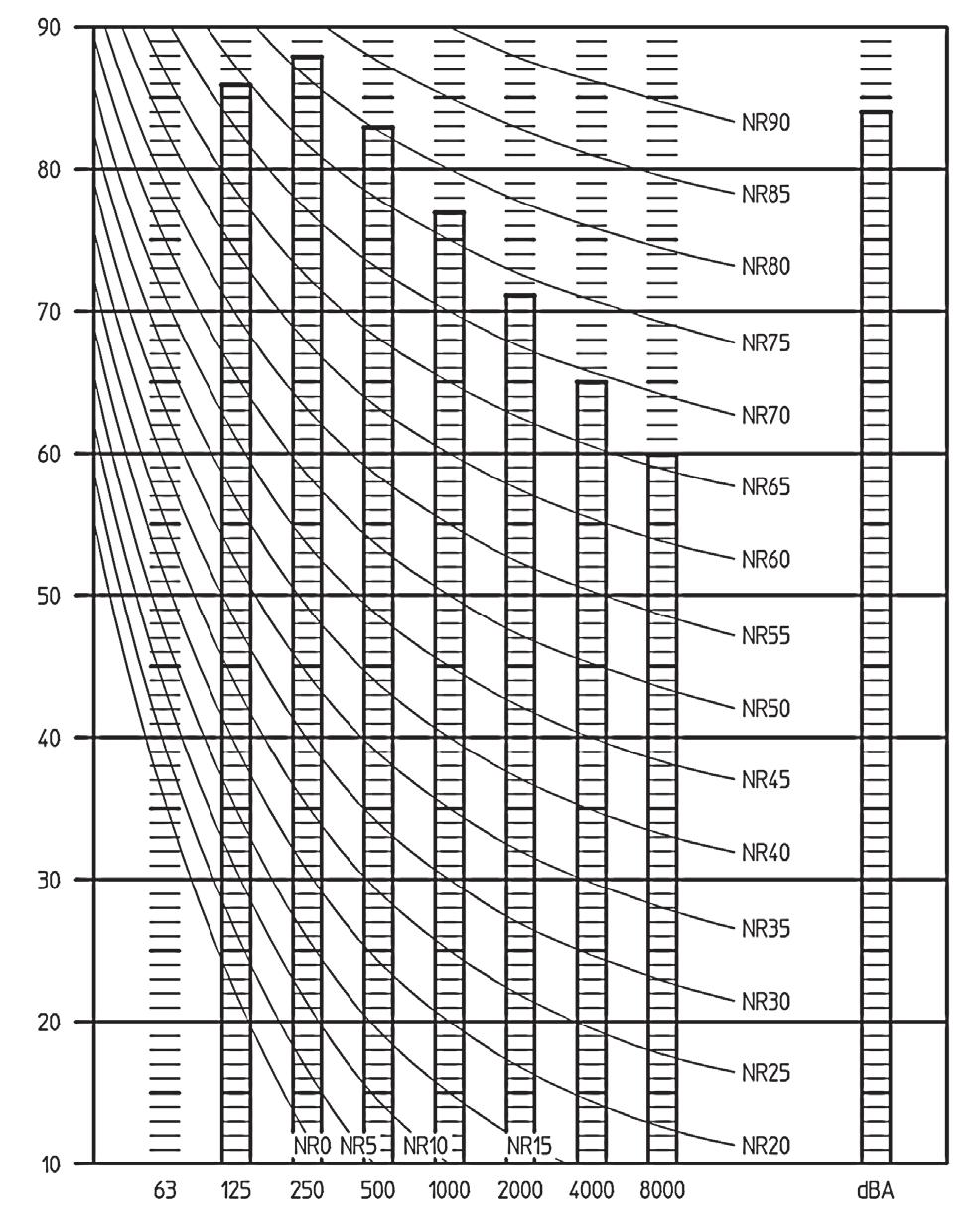
36 10 Sound data 10-2 Sound Pressure Spectrum REYAQ10P REYAQ12P Octave band sound pressure level db (0dB = bar) Octave band sound pressure level db (0dB = bar) Approximate threshold hearing for continuous noise Octave band center frequency (Hz) 3TW A NOTES 1 Over All (db): Scale 50 Hz 2 (B,G,N is already rectifi ed) A 58 Operating conditions: C 66 Power source: V 50Hz 3 Measuring place: Anechoic chamber (conversion value) 4 The operating sound is measured in anechoic chamber, if it is measured under the actual installation conditions, it is normally over the set value due to enviromental noise and sound refl ection. 5 Location of microphone. Approximate threshold hearing for continuous noise Octave band center frequency (Hz) 3TW A NOTES 1 Over All (db): Scale 50 Hz 2 (B,G,N is already rectifi ed) A 60 Operating conditions: C 67 Power source: V 50Hz 3 Measuring place: Anechoic chamber (conversion value) 4 The operating sound is measured in anechoic chamber, if it is measured under the actual installation conditions, it is normally over the set value due to enviromental noise and sound refl ection. 5 Location of microphone. Front side 1 m 1.5 m Front side 1 m 1.5 m REYAQ14P REYAQ16P Octave band sound pressure level db (0dB = bar) Octave band sound pressure level db (0dB = bar) Approximate threshold hearing for continuous noise Approximate threshold hearing for continuous noise Octave band center frequency (Hz) 3TW A NOTES 1 Over All (db): Scale 50 Hz 2 (B,G,N is already rectifi ed) A 62 Operating conditions: C 69 Power source: V 50Hz 3 Measuring place: Anechoic chamber (conversion value) 4 The operating sound is measured in anechoic chamber, if it is measured under the actual installation conditions, it is normally over the set value due to enviromental noise and sound refl ection. 5 Location of microphone. Octave band center frequency (Hz) 3TW A NOTES 1 Over All (db): Scale 50 Hz 2 (B,G,N is already rectifi ed) A 63 Operating conditions: C 70 Power source: V 50Hz 3 Measuring place: Anechoic chamber (conversion value) 4 The operating sound is measured in anechoic chamber, if it is measured under the actual installation conditions, it is normally over the set value due to enviromental noise and sound refl ection. 5 Location of microphone. Front side 1 m 1.5 m Front side 1 m 1.5 m 34 VRV Systems Outdoor Unit
37 11 Installation 11-1 Refrigerant Pipe Selection Selection of piping size NOTICE HXHD indoor units do not require a branch selector box (BS box). They only require HP/LP gas and liquid pipe connections. Other indoor units need to be connected to a branch selector box (BS box)(need 3 pipes). C. Piping between refrigerant branch kit or branch selector box and indoor unit Pipe size for direct connection to indoor unit must be the same as the connection size of the indoor unit. For HXHD indoor unit: Indoor unit Piping outer diameter size (mm) capacity type HP/LP gas pipe Liquid pipe For other indoor units: Size: determine the proper size referring to following table: A a Refnet joint Branch selector box 1, 2, 3 Indoor unit 4 HXHD indoor unit A. Piping between outdoor unit and first branch pipe Outdoor unit capacity type (Hp) Piping outer diameter size (mm) Suction gas pipe HP/LP gas pipe Liquid pipe B. Piping between refrigerant branch kits and branch selector box (BS box) Choose from the following table in accordance with the indoor unit total capacity type, connected downstream: Indoor unit capacity index B1 B3 b B2 BS BS BS 4 C1 C1 C2 C Piping outer diameter size (mm) Suction gas pipe HP/LP gas pipe Liquid pipe < x< x< x< x< x B4 Example: Total capacity connected downstream for B1 = capacity index indoor 2 + capacity index indoor 3 + capacity index indoor 4 = 225 Total capacity connected downstream for B2 = capacity index indoor 3 + capacity index indoor 4 = 145 Total capacity connected downstream for B3/B4 = capacity index indoor 1/2 = 80 Total capacity connected downstream for B5 = capacity index indoor 3 = 20 c B5 Indoor unit capacity type Suction gas pipe Liquid pipe 20, 25, 32, 40, , 80, 100, Example: The pipe thickness of the refrigerant piping shall comply with the applicable legislation. The minimal pipe thickness for R410A piping must be in accordance with the table below. In case the required pipe sizes (inch sizes) are not available, it is also allowed to use other diameters (mm sizes), taken the following into account: select the pipe size nearest to the required size. use the suitable adapters for the change-over from inch to mm pipes (field supply). Selection of refrigerant branch kits Refrigerant refnets Indoor unit capacity index Piping outer diameter size (mm) Suction gas pipe or HP/LP gas pipe Liquid pipe C C C3 125 (a) 12.7 (a) 9.5 (a) (a) HXHD indoor unit Pipe Ø Minimal thickness t (mm) When using refnet joints at the first branch counted from the outdoor unit side, choose from the following table in accordance with the capacity of the outdoor unit (example: refnet joint a) Outdoor unit Refrigerant branch kit name capacity type (Hp) 3 pipes 2 pipes 10 KHRQ23M29T KHRQ22M29T 12~16 KHRQ23M64T KHRQ22M64T 4PW (1) VRV Systems Outdoor Unit 35
38 11 Installation 11-1 Refrigerant Pipe Selection For refnets joints other than the first branch (example refnet joint b and c), select the proper branch kit model based on the total capacity index of all indoor units connected after the refrigerant branch. Indoor unit Refrigerant branch kit name capacity index 3 pipes 2 pipes <200 KHRQ23M20T KHRQ22M20T 200 x<290 KHRQ23M29T KHRQ22M29T 290 x<640 KHRQ23M64T KHRQ22M64T 640 KHRQ23M75T KHRQ22M75T Concerning refnet headers, choose from the following table in accordance with the total capacity of all the indoor units connected below the refnet header: Indoor unit Refrigerant branch kit name capacity index 3 pipes 2 pipes <200 KHRQ23M29H KHRQ22M29H 200 x<290 KHRQ23M29H KHRQ22M29H 290 x<640 KHRQ23M64H KHRQ22M64H 640 KHRQ23M75H KHRQ22M75H NOTICE Refrigerant branch kits can only be used with R410A. Maximum allowable lengths Actual pipe length between outdoor and indoor unit 100 m Example 1: a+b+c+d+e+f+g+p 100 m a+b+c+d+k+t 100 m Example 2: a+i+k 100 m a+b+e+q 100 m Example 3: a+i 100 m a+d+m 100 m Equivalent piping length between indoor and outdoor unit ð120 m equivalent pipe length of refnet to be taken 0.5 m and for header 1.0 m. Equivalent pipe length of BSVQ100 = 4 m Equivalent pipe length of BSVQ160 = 4 m Equivalent pipe length of BSVQ250 = 6 m Total piping length from outdoor to all indoor units 300 m Pipe length from first branch kit (either refnet joint or refnet header) to indoor unit 40 m [Example 1]: unit 8: b+c+d+e+f+g+p 40 m [Example 2]: unit 6: b+h+t 40 m, unit 8: i+k 40 m [Example 3]: unit 8: i 40 m, unit 2: c+k 40 m Maximum allowable height difference System piping limitations Difference in height between outdoor and indoor units H1 40 m Piping length restrictions Difference in height between lowest and heighest indoor unit H2 15 m H1 H2 Make sure to perform the piping installation within the range of the maximum allowable pipe length, allowable level difference and allowable length after branching as indicated below ("8"=HXHD125): Example 1: Branch with refnet joint a b c d e f g H1 A B C D E F G h i j k l m n BS BS BS BS BS BS BS q r s t u v w H2 Example 2: Branch with refnet joint and refnet header H1 a Example 3: Branch with refnet header a A b c d e f g h BS BS BS BS BS BS n p q r s t H2 i B j BS b c d e f g h i BS BS BS BS BS BS BS j k m n p q r m 8 7 H1 8 k H2 8 p NOTICE When the equivalent pipe length between outdoor and indoor units is 90 m or more, the size of the main liquid pipe must be increased. Never increase suction gas pipe and HP/LP gas pipe sizes. Depending on the length of the piping, the capacity may drop, but even in such a case it is possible to increase the size of the main liquid pipe. HP Liquid Ø (mm) ~ Make sure to perform the piping installation within the range of the maximum allowable pipe length, allowable level difference and allowable length after branching as indicated above Outdoor unit 2 Main pipes 3 Increase only liquid pipe size 4 First refrigerant branch kit 5 Branch selector box 6 Indoor unit 7 HXHD125 indoor unit 4PW (2) 36 VRV Systems Outdoor Unit
 Continuous cooling operation Range")

39 12 Operation range 12-1 Operation Range REYAQ-P Heating mode Cooling mode Outdoor temperature ( CWB) Startup area Continuous heating operation Outdoor temperature ( CWB) Continuous cooling operation Range for pull down operation Indoor temperature ( CDB) Indoor temperature ( CDB) Remark Operation range is valid for combination of REYAQ-P and direct expansion indoor units. 3TW A(2) VRV Systems Outdoor Unit 37


40 Daikin s unique position as a manufacturer of air conditioning equipment, compressors and refrigerants has led to its close involvement in environmental issues. For several years Daikin has had the intention to become a leader in the provision of products that have limited impact on the environment. This challenge demands the eco design and development of a wide range of products and an energy management system, resulting in energy conservation and a reduction of waste. The present publication is drawn up by way of information only and does not constitute an offer binding upon Daikin Europe N.V.. Daikin Europe N.V. has compiled the content of this publication to the best of its knowledge. No express or implied warranty is given for the completeness, accuracy, reliability or fitness for particular purpose of its content and the products and services presented therein. Specifications are subject to change without prior notice. Daikin Europe N.V. explicitly rejects any liability for any direct or indirect damage, in the broadest sense, arising from or related to the use and/or interpretation of this publication. All content is copyrighted by Daikin Europe N.V.. Daikin products are distributed by: VRV products are not within the scope of the Eurovent certification programme. Naamloze Vennootschap - Zandvoordestraat 300, B-8400 Oostende - Belgium BE RPR Oostende EEDEN CD 05/11 Copyright Daikin The present publication supersedes EEDEN Printed in Belgium by Lannoo ( a company whose concern for the environment is set in the EMAS and ISO systems. Responsible Editor: Daikin Europe N.V., Zandvoordestraat 300, B-8400 Oostende
TABLE OF CONTENTS REYHQ16-24P
 Outdoor Units VRV HEAT RECOVERY REYHQ6-2P TABLE OF CONTENTS REYHQ6-2P Specifications....................................................... Independent Unit....................................................
Air Conditioning. Technical Data. VRVIII-S heat pump EEDEN13-200_2 RXYSQ-P8Y1
 Air Conditioning Technical Data VRVIII-S heat pump EEDEN-200_2 RXYSQ-P8Y Outdoor Unit VRVIII-S heat pump RXYSQ-P8Y TABLE OF CONTENTS RXYSQ-P8Y Features.............................................................
Air Conditioning. Technical Data. VRVIII-S heat pump EEDEN13-200_2 RXYSQ-P8V1
 Air Conditioning Technical Data VRVIII-S heat pump EEDEN3-200_2 RXYSQ-P8V Outdoor Unit VRVIII-S heat pump RXYSQ-P8V TABLE OF CONTENTS RXYSQ-P8V Features.............................................................
technical data Systems RSX(Y)P-K7W1 Inverter cooling only / heat pump series
P-K7W1 Inverter cooling only / heat pump series") technical data Systems RSX(Y)P-K7W1 Inverter cooling only / heat pump series Inverter cooling only / heat pump series RSX(Y)P5,8,10K7W1 RSX(Y)P-K7W1 1 Inverter cooling only / heat pump series 1 1 Specifications
technical data Systems RSX(Y)P-K7W1 Inverter cooling only / heat pump series Inverter cooling only / heat pump series RSX(Y)P5,8,10K7W1 RSX(Y)P-K7W1 1 Inverter cooling only / heat pump series 1 1 Specifications
Heating Nom. dba Cooling Nom. dba Night quiet mode Level 1 dba Item Tie-wraps Tie-wraps Tie-wraps Tie-wraps
 RZQG71L8Y1B RZQG100L8Y1B RZQG125L8Y1B RZQG140L7Y1B Sound pressure level Heating Nom. dba 50 52 53 53 Cooling Nom. dba 48 50 51 52 Night quiet mode Level 1 dba 43 45 45 45 Standard Accessories Item Tie-wraps
Air Conditioning Technical Data FXDQ-A3 > FXDQ15A3VEB > FXDQ20A3VEB > FXDQ25A3VEB > FXDQ32A3VEB > FXDQ40A3VEB > FXDQ50A3VEB > FXDQ63A3VEB
 Air Conditioning Technical Data FXDQ-A3 > FXDQ15A3VEB > FXDQA3VEB > FXDQ25A3VEB > FXDQ32A3VEB > FXDQ40A3VEB > FXDQ50A3VEB > FXDQ63A3VEB TABLE OF CONTENTS FXDQ-A3 1 Features.............................................................
technical data air conditioning systems RQ-B7 Pair/Twin/Triple/Double Twin Application Split Sky Air
 technical data RQ-B7 Pair/Twin/Triple/Double Twin Application air conditioning systems Split Sky Air Split - Sky Air ISO14001 assures an effective environmental management system in order to help protect
Outdoor Units R-410A ARX-GV1B
 Outdoor Units R-40A ARX-GVB t A i n y U k BS r o AV t o0g i d- lt4x pur- SRAO 2 Specifications Outdoor Units R-40A ARX-GVB 2- NOMINAL CAPACITY AND NOMINAL INPUT ARX20GVB ARX25GVB ARX5GVB For combination
Air Conditioning Technical Data RZQG-L(8)Y1
Y1") Air Conditioning Technical Data RZQG-L(8)Y TABLE OF CONTENTS RZQG-L(8)Y Features............................................................. 2 2 Specifications.......................................................
Air Conditioning Technical Data RZQG-L(8)Y TABLE OF CONTENTS RZQG-L(8)Y Features............................................................. 2 2 Specifications.......................................................
Split-Sky Air RMX-JZ Super Multi Plus
 TECHNICAL DATA Split-Sky Air RMX-JZ Super Multi Plus Split Sky Air ISO400 assures an effective environmental management system in order to help protect human health and the environment from the potential
PRK PREVIEW. System. OZONE FRIENDLY R-407C Series. Inverter Heat Pump Series Heat Recovery Series PLUS Series (Heat Pump)
") PRK 00-04 PREVIEW System OZONE FRIENDLY R-407C Series Inverter Heat Pump Series Heat Recovery Series PLUS Series (Heat Pump) 3DUW#4 2XWGRRU#8QLWV 111111111111111111111111111111111111111111111111111111111111111111111
PRK 00-04 PREVIEW System OZONE FRIENDLY R-407C Series Inverter Heat Pump Series Heat Recovery Series PLUS Series (Heat Pump) 3DUW#4 2XWGRRU#8QLWV 111111111111111111111111111111111111111111111111111111111111111111111
technical data air conditioning systems RYP-L7/B7 Pair Application Split Sky Air
 technical data RYP-L7/B7 Pair Application air conditioning systems Split Sky Air Split - Sky Air ISO400 assures an effective environmental management system in order to help protect human health and the
technical data air conditioning systems RXG-C Wall Mounted, Inverter Controlled Unit Split Sky Air
 technical data RXG-C Wall Mounted, Inverter Controlled Unit air conditioning systems Split Sky Air Split - Sky Air ISO400 assures an effective environmental management system in order to help protect human
technical data air conditioning systems Round Flow Cassette FXFQ-P9VEB
 technical data Round Flow Cassette FXFQ-P9VEB air conditioning systems technical data Round Flow Cassette FXFQ-P9VEB air conditioning systems TABLE OF CONTENTS FXFQ-P9VEB 1 Specifications.......................................................
Air Conditioning. Technical Data EEDEN RXZ-N
 Air Conditioning Technical Data EEDEN14-100 RXZ-N TABLE OF CONTENTS RXZ-N 1 Features............................................................. 2 2 Specifications.......................................................
Air Conditioners Technical Data
 Air Conditioners Technical Data O u t d o o r u n i t E E D E N 2-0 0 RXG-K Outdoor Unit Pair application RXG-K TABLE OF CONTENTS RXG-K Features.............................................................
Fan Coil Units. Technical Data
 Fan Coil Units Technical Data F a n c o i l u n i t s E E D E N 1 1-4 0 0 Fan Coil Units Technical Data F a n c o i l u n i t s E E D E N 1 1-4 0 0 Table of Contents Table of Contents 3 Round Flow Cassette...
Ceiling Concealed Series FDMRN-AV1K. 50Hz. Preliminary
 Ceiling Concealed Series FDMRN-AV1K 50Hz Nomenclature Main Benefits Engineering and Physical Data Electrical Data Capacity Tables Outline and Dimensions Electrical Connection Refrigerant Piping Nomenclature
Air Conditioning. Technical Data EEDEN RXZ-N
 Air Conditioning Technical Data EEDEN15-100 RXZ-N Outdoor Unit RXZ-N TABLE OF CONTENTS RXZ-N 1 Features............................................................. 2 2 Specifications.......................................................
technical data air conditioning systems RKS-C RKS-B Pair Application, Inverter Controlled Unit Split Sky Air
 technical data RKS-C RKS-B Pair Application, Inverter Controlled Unit air conditioning systems Split Sky Air Split - Sky Air ISO400 assures an effective environmental management system in order to help
Air Conditioning. Technical Data. Round flow cassette EEDEN FXFQ-A
 Air Conditioning Technical Data Round flow cassette EEDEN16-204 FXFQ-A TABLE OF CONTENTS FXFQ-A 1 Features............................................................. 2 2 Specifications.......................................................
technical data air conditioning systems MXS-B Multi Application Split Sky Air
 technical data MXS-B Multi Application air conditioning systems Split Sky Air Split - Sky Air ISO400 assures an effective environmental management system in order to help protect human health and the environment
1 Features. Indoor Units CONCEALED CEILING UNIT FXSQ-P7VEB. VRV Systems Indoor Units
 t i t l r - I Features s e Cs m B ne d E Ue V s 7 ya P os e oc Q dvn S nr ox VF C Reduction of power consumption of 20% (compared to FXSQ-M8 series) through use of new DC fan Improved comfort thanks to
Heating. Technical Data. Daikin Altherma low temperature split EEDEN ERLQ-CV3
 Heating Technical Data Daikin Altherma low temperature split EEDEN2-725 ERLQ-CV Daikin Altherma low temperature split ERLQ-CV TABLE OF CONTENTS ERLQ-CV Features.............................................................
Split-Sky Air RP-B7 Twin/Triple/Double Twin Application
 TECHNICAL DATA Split-Sky Air RP-B7 Twin/Triple/Double Twin Application Split Sky Air ISO14001 assures an effective environmental management system in order to help protect human health and the environment
technical data air conditioning systems FCQ-D MXS-E 4-way Blow Ceiling Mounted Cassette (edited) Split Sky Air
 Split Sky Air") technical data FCQ-D MXS-E 4-way Blow Ceiling Mounted Cassette Multi (950mm Split Heat x 950mm) Pump (edited) air conditioning systems Split Sky Air Outdoor Units R40A MXS-DAVMB_E2VB_E7VB Features V i
technical data FCQ-D MXS-E 4-way Blow Ceiling Mounted Cassette Multi (950mm Split Heat x 950mm) Pump (edited) air conditioning systems Split Sky Air Outdoor Units R40A MXS-DAVMB_E2VB_E7VB Features V i
SUBMITTAL DATA - OUTDOOR UNIT VEP075N432K VRF HEAT PUMP
 VEP075N432K Job Name: Location: Schedule No.: System Designation: Engineer: Architect: Date: For: Reference Approval Review Construction FEATURES Two-pipe heat pump Hinged electrical box for ease of maintenance
Air Conditioning. Technical Data. VRV IV water cooled series EEDEN RWEYQ-T8
 Air Conditioning Technical Data VRV IV water cooled series EEDEN15-201 Outdoor Unit TABLE OF CONTENTS 1 Features............................................................. 2 2 Specifications.......................................................
Air Conditioners. Technical Data. Individual branch selector for VRV heat recovery (Individual BS box) EEDEN BSVQ P8
 EEDEN BSVQ P8") Air Conditioners Technical Data Individual branch selector for VRV heat recovery (Individual BS box) EEDEN11-200 BSVQ100-250P8 Air Conditioners Technical Data Individual branch selector for VRV heat recovery
Air Conditioners Technical Data Individual branch selector for VRV heat recovery (Individual BS box) EEDEN11-200 BSVQ100-250P8 Air Conditioners Technical Data Individual branch selector for VRV heat recovery
Air Conditioning Technical Data RZQSG-L3/9V1
 Air Conditioning Technical Data RZQSG-L/9V1 Outdoor Unit RZQSG-L/9V1 TABLE OF CONTENTS RZQSG-L/9V1 1 Features............................................................. 2 2 Specifications.......................................................
technical data air conditioning systems MA-GZ7 Multi Model Application Split Sky Air
 technical data MA-GZ7 Multi Model Application air conditioning systems Split Sky Air Split - Sky Air ISO14001 assures an effective environmental management system in order to help protect human health
Air Conditioners. Technical Data UATYQ-CY1
 Air Conditioners Technical Data R o o f t o p s E E D E N 2-2 0 UATYQ-CY Air Conditioners Technical Data R o o f t o p s E E D E N 2-2 0 UATYQ-CY Single Unit Rooftop UATYQ-CY TABLE OF CONTENTS UATYQ-CY
Technical Service Manual
 Technical Service Manual 60 Hz Low/Mid Pressure Duct Units 7 48 MBH Units 96 MBH Unit June 2009 VRF-SVM21A-EN Low and Mid Pressure Duct Units 1. Features......... 2 2. Specifications......... 3 3. Dimensions.........
Ventilation. Technical Data. Heat reclaim ventilation, humidification and air processing EEDEN VKM-GBM
 Ventilation Technical Data Heat reclaim ventilation, humidification and air processing EEDEN14-205 VKM-GBM Indoor Unit VKM-GBM TABLE OF CONTENTS VKM-GBM 1 Features.............................................................
1 Features. Outdoor Units R-410A RZQ71-140C7V1B. Split Sky Air Outdoor Units
 i r -t i l t - Outdoor Units R-40A RZQ7-40C7VB Features V 7n y CU k 0 S 4 oa o 0 d 7 4Q puz RO S Outdoor units for pair, twin, triple, double twin application The Sky Air Inverter is developed for use
Air Conditioning. Technical Data EEDEN RXJ-L
 ir Conditioning Technical Data EEDEN5-0 RXJ-L Outdoor Unit RXJ-L TLE OF CONTENTS RXJ-L Features............................................................. Specifications.......................................................
ROOF TOP (SERIES SR) 10.8 TO 103 KW 37,000 TO 351,000 Btuh
 10.8 TO 103 KW 37,000 TO 351,000 Btuh") ROOF TOP (SERIES ) 10.8 TO 103 KW 37,000 TO 351,000 Btuh These rooftop units are complete, self contained air conditioners fully assembled, wire, charged and tested prior to shipment, each unit is delivered
ROOF TOP (SERIES ) 10.8 TO 103 KW 37,000 TO 351,000 Btuh These rooftop units are complete, self contained air conditioners fully assembled, wire, charged and tested prior to shipment, each unit is delivered
technical data air conditioning systems 600x600 4-Way Blow Ceiling Mounted Cassette FXZQ-M9V1B
 technical data 600x600 4-Way Blow Ceiling Mounted Cassette FXZQ-M9V1B air conditioning systems technical data 600x600 4-Way Blow Ceiling Mounted Cassette FXZQ-M9V1B air conditioning systems Indoor Units
Technical Service Manual. TVR LX Systems Low Static Pressure Duct Units with DC Fan Motor V/50-60Hz/1ph
 Technical Service Manual TVR LX Systems Low Static Pressure Duct Units with DC Fan Motor 220-240V/50-60Hz/1ph August 2015 1. Features...2 2. Specifications...3 3. Dimensions...7 4.Service Spaces...8 5.Piping
HCH6. Product Specifications
 HCH6 Product Specifications HIGH EFFICIENCY 16 SEER TWO- STAGE HEAT PUMP WITH OBSERVERt COMMUNICATING CONTROL SYSTEM 2 THRU 5 TONS SPLIT SYSTEM 208/230 Volt, 1- phase, 60 Hz REFRIGERATION CIRCUIT S Copeland
R410A TECHNICAL MANUAL. Inverter Single Split Series Air Conditioner. FTK-J, FTXN-J Series. Cooling only & Heatpump [50Hz] TM-5WMY-J-ST-A2
![R410A TECHNICAL MANUAL. Inverter Single Split Series Air Conditioner. FTK-J, FTXN-J Series. Cooling only & Heatpump [50Hz] TM-5WMY-J-ST-A2](/thumbs/87/97223604.jpg "R410A TECHNICAL MANUAL. Inverter Single Split Series Air Conditioner. FTK-J, FTXN-J Series. Cooling only & Heatpump [50Hz] TM-5WMY-J-ST-A2") R410A TECHNICAL MANUAL Inverter Single Split Series Air Conditioner FTK-J, FTXN-J Series Cooling only & Heatpump [50Hz] TM-5WMY-J-ST-A2 Table of Contents Table of Contents Nomenclature...1 Indoor...1 Outdoor...1
R410A TECHNICAL MANUAL Inverter Single Split Series Air Conditioner FTK-J, FTXN-J Series Cooling only & Heatpump [50Hz] TM-5WMY-J-ST-A2 Table of Contents Table of Contents Nomenclature...1 Indoor...1 Outdoor...1
Four-way Cassette Type
 Four-way Cassette Type Four-way Cassette Type 1. Features... 9 2. Specifications... 12 3. Dimensions... 17 4. Service Space... 18 5. Wiring Diagrams... 19 6. Capacity Tables... 21 7. Electric Characteristics...
PCXAU1601. VRV AHU System STANDARD SERIES AHUR-CAVJ/DAVJ/DABVJ OUTDOOR AIR SERIES AHUR-CALJ/DALJ/DABLJ. Heat Pump 50/60 Hz R-410A
 PCXAU161 VRV AHU System STANDARD SERIES AHUR-CAVJ/DAVJ/DABVJ OUTDOOR AIR SERIES AHUR-CALJ/DALJ/DABLJ Heat Pump 5/6 Hz R-1A An industry first, the VRV air handling unit has been designed and engineered
MODEL: DCT 35 INV-Si DCT 50 INV-Si DCT 70 INV-Si DCT 100 INV-Si DCT 140 INV-Si DCT 170 INV-Si
 MODEL: DCT 35 INV-Si DCT 50 INV-Si DCT 70 INV-Si DCT 100 INV-Si DCT 140 INV-Si DCT 170 INV-Si Part 1 General Information.. 1 Part 2 Indoor Units. Part 3 Outdoor Units. Part 5 Control... Part 6 Control
PACKAGE UNIT PCA340U TECHNICAL SELECTION DATA. -10 o C UNIT FEATURES SPECIFICATION SUMMARY UNIT OPTIONS CONTROL OPTIONS UNIT COMPLIANCE.
 TECHNICAL SELECTION DATA PACKAGE UNIT + o C -10 o C 3 THREE PHASE SCROLL TWO STAGE CENTRIFUGAL LOUVRE LIANT SCROLL RESSOR AXIAL UNIT FEATURES SPECIFICATION SUMMARY Scroll Compressor Multiple Speed Outdoor
Air Conditioning. Technical Data. Slim concealed ceiling unit EEDEN FXDQ-A
 Air Conditioning Technical Data Slim concealed ceiling unit EEDEN14-204 FXDQ-A TABLE OF CONTENTS FXDQ-A 1 Features............................................................. 2 2 Specifications.......................................................
Low Static Pressure Duct(V shape evaporator)
") Low Static Pressure Duct (V shape evaporator) 1. Features... 116 2. Specifications... 118 3. Dimensions... 121 4. Service Spaces... 123 5. Piping Diagrams... 124 7.Fan Performance... 126 8.Capacity Tables...
Low Static Pressure Duct (V shape evaporator) 1. Features... 116 2. Specifications... 118 3. Dimensions... 121 4. Service Spaces... 123 5. Piping Diagrams... 124 7.Fan Performance... 126 8.Capacity Tables...
PH120. Rooftop Packaged. R410a Refrigerant PERFORMANCE DATA OUTDOOR COIL ENTERING TEMPERATURE 0 C
 PH120 R410a Refrigerant Rooftop Packaged INDOOR COIL ENTERING AIR TEMP 0 c DB WB 21 23 25 27 29 31 PERFORMANCE DATA OUTDOOR COIL ENTERING TEMPERATURE 0 C 30 35 40 45 Cap Cap Cap Cap 17 115.3 70.7 11.5
UMXCA/UMXCBA ECVA/ECVBA
 OUTDOOR UNITS Models: 801.1 1001.1 1201.1 1501.1 1602.2 2002.2 2402.2 3002.2 3502.2 4002.2 4502.2 Cooling Capacities: from 25,9 kw to 134,7 kw Heating Capacities: from 27,3 kw to 142,4 kw INDOOR UNITS
Compact Four-way Cassette Type
 1. Features... 34 2. Specifications... 35 3. Dimensions... 37 4. Service Spaces... 38 5. Piping Diagrams (EXV beside)... 39 6. Wiring Diagrams... 40 7. Capacity Tables... 41 8. Electrical Characteristics...
R4A4. Product Specifications EFFICIENT 14 SEER AIR CONDITIONER ENVIRONMENTALLY SOUND R 410A REFRIGERANT
 R4A4 Product Specifications EFFICIENT 14 SEER AIR CONDITIONER ENVIRONMENTALLY SOUND R 410A REFRIGERANT 1 1/2 THRU 5 TONS SPLIT SYSTEM 208/2 Volt, 1 phase, 60 Hz REFRIGERATION CIRCUIT Scroll compressors
WCA4**4. Product Specifications
 WCA4**4 AIR CONDITIONER EFFICIENT 14 SEER ENVIRONMENTALLY SOUND R 410A REFRIGERANT 1½ THRU 5 TONS SPLIT SYSTEM 208/2 Volt, 1 phase, 60 Hz Use of the AHRI Certified TM Mark indicates a manufacturer s participation
SINGLE. Technical Data Book. Big Duct for Europe (R410A, 50Hz, H/P) Model : AC180JNHPKH/EU AC180JXAPNH/EU AC200JNHPKH/EU AC200JXAPNH/EU
 Model : AC180JNHPKH/EU AC180JXAPNH/EU AC200JNHPKH/EU AC200JXAPNH/EU") SINGLE Technical Data Book Big Duct for Europe (R410A, 50Hz, H/P) Model : AC180JNHPKH/EU AC180JXAPNH/EU AC200JNHPKH/EU AC200JXAPNH/EU History Version Modification Date Remark Ver.1.0 Release SINGLE Big
SINGLE Technical Data Book Big Duct for Europe (R410A, 50Hz, H/P) Model : AC180JNHPKH/EU AC180JXAPNH/EU AC200JNHPKH/EU AC200JXAPNH/EU History Version Modification Date Remark Ver.1.0 Release SINGLE Big
1. Features Specifications Dimensions Service Spaces Piping Diagrams Wiring Diagrams...
 MCAC-VTSM-2013-08 1. Features... 264 2. Specifications... 265 3. Dimensions... 268 4. Service Spaces... 272 5. Piping Diagrams... 273 6. Wiring Diagrams... 274 7. Capacity Tables... 276 8. Electrical Characteristics...
CHP SERIES FEATURES. High Pressure Control Three Phase Models. Low Ambient Fan Cycle Control Three Phase Models
 CHP SERIES FEATURES HEAT PUMP CONDENSING UNIT 220V-1-50 380/420V-3-50 High Efficiency Scroll Compressors Proven Reliability in Harsh Environments Prepainted Galvanized Steel Triple Step Paint Process One
Service manual MIV V4+ Indoor units
 Service manual MIV V4+ Indoor units Floor Standing MVF22A-VA1 MVF28A-VA1 MVF36A-VA1 MV5A-VA1 MVF56A-VA1 MVF71A-VA1 MVF80A-VA1 MVB22A-VA1 MVB28A-VA1 MVB36A-VA1 MVB45A-VA1 MVB56A-VA1 MVB71A-VA1 MVB80A-VA1
RAC. Technical Data Book. RAC for North America (Inv, R410A, 60Hz, HP)
") RAC Technical Data Book RAC for North America (Inv, R410A, 60Hz, HP) Model : AR09/12JSALBWKNCV AR09/12JSALBWKXCV AR09/12/18/24JSFLBWKNCV AR09/12/18/24JSFLBWKXCV History Version Modification Date Remark
RAC Technical Data Book RAC for North America (Inv, R410A, 60Hz, HP) Model : AR09/12JSALBWKNCV AR09/12JSALBWKXCV AR09/12/18/24JSFLBWKNCV AR09/12/18/24JSFLBWKXCV History Version Modification Date Remark
Split. Air Conditioning Technical Data FTXC-A > FTXC25AV1B > FTXC35AV1B > FTXC50AV1B > FTXC60AV1B
 Split Air Conditioning Technical Data FTXC-A > FTXC25AV1B > FTXC35AV1B > FTXC50AV1B > FTXC60AV1B Indoor Unit FTXC-A TABLE OF CONTENTS FTXC-A 1 Features.............................................................
Technical Service Manual. TVR LX Systems Medium Static Pressure Duct Units with DC Fan Motor V/50-60Hz/1ph
 Technical Service Manual TVR LX Systems Medium Static Pressure Duct Units with DC Fan Motor 220-240V/50-60Hz/1ph August 20 Medium Static Pressure Duct Unit With DC Fan Motor 1. Features...2 2. Specifications...4
technical data Systems FXMQ-MVE Conceiled ceiling unit (large)
") technical data Systems FXMQ-MVE Conceiled ceiling unit (large) FXMQ-MVE 11 Concealed ceiling unit (large) 11 1 Features...2 2 Specifications Technical specifications...3 Electrical specifications...4 Safety
technical data Systems FXMQ-MVE Conceiled ceiling unit (large) FXMQ-MVE 11 Concealed ceiling unit (large) 11 1 Features...2 2 Specifications Technical specifications...3 Electrical specifications...4 Safety
Low Static Pressure Duct (V shape evaporator)
") MCAC-VTSM-2015-04 Low Static Pressure Duct Type Low Static Pressure Duct (V shape evaporator) 1. Features... 100 2. Specifications... 101 3. Dimensions... 105 4.Service Spaces... 106 5.Piping Diagrams...
MCAC-VTSM-2015-04 Low Static Pressure Duct Type Low Static Pressure Duct (V shape evaporator) 1. Features... 100 2. Specifications... 101 3. Dimensions... 105 4.Service Spaces... 106 5.Piping Diagrams...
VRF Technical Data Book
 VRF Technical Data Book DVM S Eco for America (R410A, 60Hz, HR) Model : AM***NXMDCR/AA History Version Modification Date Remark Ver.1.0 Released DVM S Eco HR for North America TDB 18.02.28 Ver.1. Re 18.0
TECHNICAL GUIDE GENERAL SPECIFICATIONS COMMERCIAL SPLIT-SYSTEM COOLING UNITS FOUR PIPE SYSTEM OUTDOOR UNIT:
 036-21323-001-B-0202 GENERAL SPECIFICATIONS OUTDOOR UNIT: Two independent refrigerant circuits Inherently protected fan motors Two independent scroll compressors V-Coil Design Exterior service port connections
Job Name: Tag# 3 Port, 2-Ton Outdoor Heat Pump
 Job Name: Tag# Submittal Data Sheet 3 Port, 2-Ton Outdoor Heat Pump 3MXS24RMVJU Efficiency SEER EER HSPF COP Non-Ducted 18 12.7 12.5 3.53 Ducted 14 9.7 8.2 3.44 Mixed 15.95 11.2 10.35 3.49 Performance
Split-Sky Air FDYP-B7 Concealed Ceiling Unit
 TECHNICAL DATA Split-Sky Air FDYP-B7 Concealed Ceiling Unit Split Sky Air ISO14001 assures an effective environmental management system in order to help protect human health and the environment from the
SPLIT TYPE ROOM AIR CONDITIONER WALL MOUNTED TYPE
 SPLIT TYPE ROOM AIR CONDITIONER WALL MOUNTED TYPE Indoor unit ASYA24LCC ASYA24LCC ASYA24LCC Outdoor unit AOYR24LCC AOYR24LCD AOYR24LCL CONTENTS SPECIFICATIONS..................1 DIMENSIONS.....................
PCXDMT1601. VRV AHU System STANDARD SERIES AHUR-CAVJ/DAVJ/DABVJ OUTDOOR AIR SERIES AHUR-CALJ/DALJ/DABLJ. Heat Pump 50/60 Hz R-410A
 PCXDMT1601 VRV AHU System STANDARD SERIES AHUR-CAVJ/DAVJ/DABVJ OUTDOOR AIR SERIES AHUR-CALJ/DALJ/DABLJ Heat Pump 50/60 Hz R-10A Airport Lobby Hospital Factory Shopping Mall Sports Hall Showroom Warehouse
FDYMP-D, FDP-D, FGP-D, FDYP-E, FGYP-E
 R407C TECHNICAL MANUAL Split Systems Air Conditioner Ducted Blower D & E Series FDMP-D, FDYMP-D, FDP-D, FGP-D, FDYP-E, FGYP-E series Cooling only & Heatpump [50Hz] Table of Contents Table of Contents
R4A5. Product Specifications EFFICIENT 14 SEER/ EER AIR CONDITIONER ENVIRONMENTALLY SOUND R 410A REFRIGERANT
 ENVIRONMENTALLY SOUND REFRIGERANT R4A5 Product Specifications EFFICIENT 14 SEER/11.7 12.2 EER AIR CONDITIONER ENVIRONMENTALLY SOUND R 410A REFRIGERANT 1 1/2 THRU 5 TONS SPLIT SYSTEM 208/230 Volt, 1 phase,
TSTAT0201CW (Sold Separately) Qualifying models only. Max. Fuse or Breaker
 Qualifying models only. Max. Fuse or Breaker") HVA9 Product Specifications HIGH EFFICIENCY UP TO 19 SEER VARIABLE SPEED AIR CONDITIONER WITH OBSERVER COMMUNICATING CONTROL SYSTEM 2 THRU 5 TONS SPLIT SYSTEM 208 230 Volt, 1 phase, 60 Hz REFRIGERATION
HVA9 Product Specifications HIGH EFFICIENCY UP TO 19 SEER VARIABLE SPEED AIR CONDITIONER WITH OBSERVER COMMUNICATING CONTROL SYSTEM 2 THRU 5 TONS SPLIT SYSTEM 208 230 Volt, 1 phase, 60 Hz REFRIGERATION
HSH5. Product Specifications. Quiet Comfort DXC 1500
 ENVIRONMENTALLY SOUND REFRIGERANT HSH5 Quiet Comfort DXC 1500 Product Specifications 15 SINGLE STAGE HEAT PUMP WITH OBSERVER COMMUNICATING CONTROL SYSTEM 1 1/2 THRU 5 TONS SPLIT SYSTEM 208 / 230 Volt,
Product Data PH3Z 13 SEER SINGLE -PACKAGED HEAT PUMP SYSTEM WITH R -22 REFRIGERANT SINGLE AND THREE PHASE 2-5 NOMINAL TONS ( )
") 13 SEER SINGLE -PACKAGED HEAT PUMP SYSTEM WITH R -22 REFRIGERANT SINGLE AND THREE PHASE 2-5 NOMINAL TONS (024-0) Product Data Fig. 1 - Unit 664B Single -Packaged Heat Pump Units with: S easy installation
13 SEER SINGLE -PACKAGED HEAT PUMP SYSTEM WITH R -22 REFRIGERANT SINGLE AND THREE PHASE 2-5 NOMINAL TONS (024-0) Product Data Fig. 1 - Unit 664B Single -Packaged Heat Pump Units with: S easy installation
High Wall Type ( 2 Series )
") Jan.05' Engineering Data High Wall Type ( 2 Series ) Indoor Unit MMK-AP0072H MMK-AP0092H MMK-AP0122H 1. Equipments 2. Technical Specifications 3. Dimensional Drawing 4. Wiring Diagram 5. Refrigerant Cycle
Jan.05' Engineering Data High Wall Type ( 2 Series ) Indoor Unit MMK-AP0072H MMK-AP0092H MMK-AP0122H 1. Equipments 2. Technical Specifications 3. Dimensional Drawing 4. Wiring Diagram 5. Refrigerant Cycle
GPC14H. 2- to 5-Ton Packaged Air Conditioner 14 SEER. Cooling Capacity: 24,000-57,500 BTU/H
 H Cooling Capacity: 24,000-57,500 BTU/H 2- to 5-Ton Packaged Air Conditioner 14 SEER Contents Nomenclature... 2 Product Specifications... 3 Expanded Cooling Data... 4 Airflow Data... 16 Heater Kit Specifications...
VRF. For Commercial and Light Commercial
 118 VRF For Commercial and Light Commercial 119 SOLUTIONS SMALL OFFICES Fujitsu General provides perfect total air conditioning systems that take into account energy saving, low noise, comfortable airflow,
RCD Air Cooled Condensing Unit (50/60 Hz)
") Environment friendly Easy to access components More efficient air cooled condenser coils Easy to install and maintain The Saudi Factory for Air Conditioning Units RCD Air Cooled Condensing Unit (50/60
Environment friendly Easy to access components More efficient air cooled condenser coils Easy to install and maintain The Saudi Factory for Air Conditioning Units RCD Air Cooled Condensing Unit (50/60
SINGLE. Technical Data Book. 4Way Cassette S for Nordic (R410A, 50Hz) Model : AC***JN4CEH/EU (ODU: AC***JXSC*H/EU)
 Model : AC***JN4CEH/EU (ODU: AC***JXSC*H/EU)") SINGLE Technical Data Book 4Way Cassette S for Nordic (R4A, 5Hz) Model : AC***JN4CEH/EU (ODU: AC***JXSC*H/EU) History Version Modification Date Remark Ver.1. Released SINGLE for Nordic TDB 15.3.. Ver.1.1
SINGLE Technical Data Book 4Way Cassette S for Nordic (R4A, 5Hz) Model : AC***JN4CEH/EU (ODU: AC***JXSC*H/EU) History Version Modification Date Remark Ver.1. Released SINGLE for Nordic TDB 15.3.. Ver.1.1
EFFICIENCY 17 SEER TWO STAGE AIR CONDITIONER WITH OBSERVER
 ENVIRONMENTALLY SOUND REFRIGERANT HCA7 QuietComfort DXT+ Product Specifications HIGH EFFICIENCY 17 SEER TWO STAGE AIR CONDITIONER WITH OBSERVER COMMUNICATING CONTROL SYSTEM 2 THRU 5 TONS SPLIT SYSTEM 208/230
N4A6. Product Specifications
 ENVIRONMENTALLY SOUND REFRIGERANT N4A6 Product Specifications EFFICIENT UP TO 16.5 SEER/12.2 13.0 EER AIR CONDITIONER ENVIRONMENTALLY SOUND R 410A REFRIGERANT 1 1/2 THRU 5 TONS SPLIT SYSTEM 208/2 Volt,
TSA6. Product Specifications. SmartComfort TXC 5600
 ENVIRONMENTALLY SOUND REFRIGERANT TSA6 SmartComfort TXC 5600 Product Specifications 16 SEER SINGLE STAGE AIR CONDITIONER WITH OBSERVER COMMUNICATING CONTROL SYSTEM 1½ THRU 5 TONS SPLIT SYSTEM 208 / 230
S6BQ Series TECHNICAL SPECIFICATIONS. FEATURES and BENEFITS. Split System 2-Stage Air Conditioner. 7 1/2 and 10 Ton rated at 11.2 EER and 12.
 TECHNICAL SPECIFICATIONS S6BQ Series Split System 2-Stage Air Conditioner 7 1/2 and 10 Ton rated at 11.2 EER and 12.9 IEER The S6BQ Series of air conditioners offers exceptional performance. The unit,
Concealed Ducted Split Series R22
 Concealed Ducted Split Series R22 24-60 MBH Ducted Split with Hermetic Compressor Tropical 50 Hz For more technical information please visit Table of Contents INTRODUCTION 2 NOMENCLATURE 2 UNIT RATING
N2AE - 50 Hz PRODUCT SPECIFICATIONS
 ISO 9001:2000 REGISTERED N2AE - 50 Hz PRODUCT SPECIFICATIONS 50 Hz AIR CONDITIONING CONDENSING UNIT 230 Volt, 1-phase, 50 Hz in 1½, 2, 2½, 3, 4 tons 400 Volt, 3-phase, 50 Hz in 3, 3½, 4, 5 tons REFRIGERATION
R22 TECHNICAL MANUAL. Split Unit Air Conditioner Ceiling Cassette C & E Series FF-C, FHC-E, FFY-C, FHYC-E. Cooling only & Heatpump [50Hz]
![R22 TECHNICAL MANUAL. Split Unit Air Conditioner Ceiling Cassette C & E Series FF-C, FHC-E, FFY-C, FHYC-E. Cooling only & Heatpump [50Hz]](/thumbs/93/117983102.jpg "R22 TECHNICAL MANUAL. Split Unit Air Conditioner Ceiling Cassette C & E Series FF-C, FHC-E, FFY-C, FHYC-E. Cooling only & Heatpump [50Hz]") R22 TECHNICAL MANUAL Split Unit Air Conditioner Ceiling Cassette C & E Series FF-C, FHC-E, FFY-C, FHYC-E Cooling only & Heatpump [50Hz] Table of Contents Table of Contents Nomenclature...1 Indoor...1
R22 TECHNICAL MANUAL Split Unit Air Conditioner Ceiling Cassette C & E Series FF-C, FHC-E, FFY-C, FHYC-E Cooling only & Heatpump [50Hz] Table of Contents Table of Contents Nomenclature...1 Indoor...1
DUCT type. SPLIT TYPE AIR CONDITIONER (50Hz) Models Indoor unit Outdoor unit C O N T E N T S
 Models Indoor unit Outdoor unit C O N T E N T S") SPLIT TYPE AIR CONDITIONER (50Hz) DUCT type Models Indoor unit Outdoor unit RD-90EB RO-90EPB C O N T E N T S SPECIFICATIONS... OUTLINE AND DIMENSIONS... CIRCUIT DIAGRAM...5 REFRIGERANT SYSTEM DIAGRAM...6
SPLIT TYPE AIR CONDITIONER (50Hz) DUCT type Models Indoor unit Outdoor unit RD-90EB RO-90EPB C O N T E N T S SPECIFICATIONS... OUTLINE AND DIMENSIONS... CIRCUIT DIAGRAM...5 REFRIGERANT SYSTEM DIAGRAM...6
CXAM. Options. Accessories
 CXAM Reversible air-to-water scroll heat pump Customer benefits Life cycle effectiveness Efficiency and sound level without compromise All year round operation Extreme reliability and durability Wide application
Product Data PH15NB. 15SEERSplitSystemHeatPump with R---410A Refrigerant 1.5 To 5 Nominal Tons AVAILABLE SIZES:
 15SEERSplitHeatPump with R---410A Refrigerant 1.5 To 5 Nominal Tons Product Data AVAILABLE SIZES: Nominal sizes are available from 018 through 060 to meet the needs of residential and light commercial
SPLIT DUCTED UNIT SCA300C / SCA300E TECHNICAL SELECTION DATA SPECIFICATION SUMMARY UNIT FEATURES CONTROL OPTIONS UNIT COMPLIANCE
 TECHNICAL SELECTION DATA SPLIT DUCTED UNIT 3 THREE PHASE SCROLL TWO STAGE CENTRIFUGAL LOUVRE AXIAL UNIT FEATURES Scroll Compressor Multiple Speed Outdoor Fans Louvred Outdoor Coil Guard Pre-charged with
P5RF Series Single Packaged Air Conditioner Single Phase
 TECHNICAL SPECIFICATIONS P5RF Series Single Packaged Air Conditioner Single Phase 15 SEER, 12 EER, R-410A 2 thru 5 Ton Units Cooling: 24,000 to 57,500 Btuh The P5 Series single packaged air conditioners
Fan Coil Units. Technical Data ECDEN FWL-DT/DF
 Fan Coil Units Technical Data ECDEN10-400 FWL-DT/DF Fan Coil Units Technical Data ECDEN10-400 FWL-DT/DF TABLE OF CONTENTS FWL-DT/DF 1 Features.............................................................
S5BP Series TECHNICAL SPECIFICATIONS. FEATURES and BENEFITS
 TECHNICAL SPECIFICATIONS S5BP Series Split System Air Conditioner 71/2 Ton Energy Star rated at 11.7 EER and 11.8 IEER 10 Ton rated at 11.2 EER and 11.5 IEER R-410A Refrigerant The S5BP Series of air conditioners
Engineering Data Book. High Static Duct 8, 10HP Digital Inverter. Indoor Unit. Outdoor Unit
 E10-1 High Static Duct 8, 10HP Digital Inverter Engineering Data Book Indoor Unit RAV-SM2242DT-E RAV-SM2802DT-E RAV-SM2242DT-TR RAV-SM2802DT-TR Outdoor Unit RAV-SM2244AT8-E RAV-SM2804AT8-E Contents 1 Specifications..............................................................
GPC14H 2- to 5-Ton Packaged Air Conditioner Up to 14 SEER
 Cooling Capacity: 24,000-57,500 BTU/H H 2- to 5-Ton Packaged Air Conditioner Up to 14 SEER Contents Nomenclature... 2 Product Specifications... 3 Expanded Cooling Data... 5 Airflow Data... 18 Heater Kit
Multi-Room Ductless heat-pump systems Submittal Data: MULTI56HP230V1AO 56,000 BTUH Super +Multi-port Heat Pump System Job Name Location Date
 Multi-Room Ductless heat-pump systems Submittal Data: 56,000 BTUH Super +Multi-port Heat Pump System Job Name Location Date Purchaser Engineer Submitted To For Reference Approval Construction Unit Designation
WQL/WQH/WQRC 524 to 1204
 Chiller / Close control / Water terminals WQL/WQH/WQRC 524 to 1204 Water Cooled Water Chillers Cooling Only, Heat Pump and Condenserless Versions Engineering Data Manual 155 to 30 kw 170 to 370 kw Features
SLH 1202 to Air-to-Water Reverse Cycle Heat Pumps. With Screw Compressors. 261 to 775 kw. 287 to 853 kw
 Air-to-Water Reverse Cycle Heat Pumps SLH 1202 to 3804 With Screw Compressors 261 to 775 kw 287 to 853 kw Technical Brochure TM SLH-A.2GB Date : November 2004 Supersedes : TM SLH-A.1GB/05.04 Design Features
Reversible air-to-water scroll heat pumps
 Reversible air-to-water scroll heat pumps Model CXAO 120 to 290 Cooling capacity: 420-1030 kw Heating capacity: 475-1175 kw CG-PRC027A-GB Table of Contents Model number description...4 Technical specifications...5
Split-Sky Air FAYP-B Wall Mounted Unit
 TECHNICAL DATA Split-Sky Air FAYP-B Wall Mounted Unit Split Sky Air ISO14001 assures an effective environmental management system in order to help protect human health and the environment from the potential
ROOF TOP PACKAGE UNITS
 ROOF TOP PACKAGE UNITS HIEER : 3-25 Tons PRODUCT DATA BOOK Introduction Roof Top Package units have been developed & produced to provide not only the ultimate indoor comfort, but also to guarantee long
Engineering Data Book. High Static Duct 8, 10HP Digital Inverter. Indoor Unit. Outdoor Unit
 E0--2 High Static Duct 8, 0HP Digital Inverter Engineering Data Book Indoor Unit RAV-SM2242DT-E RAV-SM2802DT-E RAV-SM2242DT-TR RAV-SM2802DT-TR Outdoor Unit RAV-SM2244AT8-E RAV-SM2804AT8-E Contents Specifications..............................................................