Fan Coil Units. Technical Data ECDEN FWL-DT/DF
|
|
|
- Elizabeth Waters
- 6 years ago
- Views:
Transcription


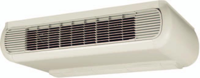
1 Fan Coil Units Technical Data ECDEN FWL-DT/DF


2 Fan Coil Units Technical Data ECDEN FWL-DT/DF
3 TABLE OF CONTENTS FWL-DT/DF 1 Features Specifications Technical Specifications 2-pipe Technical Specifications 4-pipe Electrical Specifications 2-pipe and 4-pipe Options Options Control systems Control Systems Capacity tables Cooling Capacity Tables - 2-pipe Cooling Capacity Tables - 4-pipe Capacity Correction Factor Heating Capacity Tables - 2-pipe Heating Capacity Tables - 4-pipe Power consumption - 2-pipe Power consumption - 4-pipe Dimensional drawings Dimensional Drawings Wiring diagrams Wiring Diagrams - Single Phase Sound data Sound Level Data - 2-pipe Sound Level Data - 4-pipe Installation Installation Method Operation range Operation Range Hydraulic performance Water Pressure Drop Curve Evaporator - Cooling 2-pipe Water Pressure Drop Curve Evaporator - Heating 2-pipe Water Pressure Drop Curve Evaporator - Heating 4-pipe Fan coil Indoor Unit 1

4 t i n l F i / o r T c o o - n d L na F I 1 Features n U U D C D W Quick fixing system for wall or ceiling mounted installation Pre-assembled 3-way/4-port on/off valves are available Valve packages are insulated, no extra drain pan required Valve packages contain balancing valves and sensor pocket Fast-on connections for electrical options: no tools needed The air filter can easily be removed for cleaning 2 Fan coil Indoor Unit
5 2 Specifications FWL01DATN 6V3/TV6V3 FWL02DATN 6V3/TV6V3 FWL03DATN 6V3/TV6V3 FWL04DATN 6V3/TV6V3 FWL06DATN 6V3/TV6V3 FWL08DATN 6V3/TV6V3 FWL10DATN 6V3/TV6V3 2-1 Technical Specifications 2-pipe Cooling capacity Total capacity High kw 1.54 (1) 2.09 (1) 2.93 (1) 4.33 (1) 4.77 (1) 6.71 (1) 8.02 (1) Nom. kw 1.24 (1) 1.81 (1) 2.38 (1) 3.27 (1) 3.87 (1) 5.27 (1) 6.24 (1) Low kw 1.04 (1) 1.45 (1) 1.76 (1) 2.51 (1) 3.17 (1) 3.97 (1) 4.11 (1) Sensible capacity High kw 1.20 (1) 1.51 (1) 2.11 (1) 3.15 (1) 3.65 (1) 4.91 (1) 5.96 (1) Nom. kw 0.97 (1) 1.31 (1) 1.70 (1) 2.45 (1) 2.92 (1) 3.83 (1) 4.63 (1) Low kw 0.79 (1) 1.05 (1) 1.26 (1) 1.80 (1) 2.32 (1) 2.84 (1) 3.05 (1) Heating capacity 2-Pipe High kw 2.14 (2) 2.57 (2) 3.81 (2) 5.63 (2) 6.36 (2) 7.83 (2) (2) Medium kw 1.73 (2) 2.18 (2) 3.08 (2) 4.30 (2) 5.21 (2) 6.23 (2) 7.80 (2) Low kw 1.43 (2) 1.79 (2) 2.28 (2) 3.29 (2) 4.24 (2) 4.77 (2) 5.24 (2) High W Nom. W Low W Dimensions Unit Height mm 564 Width mm ,194 1,404 Depth mm Weight Unit kg Operation weight kg - Casing Colour Plastic and metal RAL9010 Material Plastic + sheet metal Heat exchanger Rows Quantity 2 3 Stages Quantity Fin pitch mm Face area m² Water volume l Fan Type Centrifugal multi-blade, double suction Quantity 1 2 Air flow rate High m³/h ,011 1,393 Medium m³/h ,022 Low m³/h Available pressure High Pa - Fan motor Speed Steps 3 (high, medium, low) Model Closed induction, B class insulation, winding thermal cut-out Sound power level High dba Nom. dba Low dba Water flow Cooling l/h ,154 1,343 Heating l/h ,154 1,343 Water pressure drop Cooling kpa Heating kpa Air filter Plastic Insulation material Class 1 self-extinguishing Vibration insulation Rubber ring for fan motor Water connections Std. heat exchanger inch 1/2 3/4 Piping connections Drain OD mm - Notes (1) Cooling: 2 pipe: air 27ºCDB, 19ºCWB; entering water 7ºC; leaving water 12ºC (2) Heating: 2 pipe: air 20ºCDB; entering water 70ºC; leaving water 60ºC (3) Air flow at 0Pa ESP Fan coil Indoor Unit 3
6 2 Specifications FWL01DAFN6 V3/FV6V3 FWL02DAFN6 V3/FV6V3 FWL03DAFN6 V3/FV6V3 FWL04DAFN6 V3/FV6V3 FWL06DAFN6 V3/FV6V3 FWL08DAFN6 V3/FV6V3 FWL10DAFN6 V3/FV6V3 2-2 Technical Specifications 4-pipe Cooling capacity Total capacity High kw 1.46 (1) 1.90 (1) 2.87 (1) 4.33 (1) 4.67 (1) 6.64 (1) 7.88 (1) Nom. kw 1.24 (1) 1.62 (1) 2.33 (1) 3.27 (1) 3.81 (1) 5.23 (1) 6.16 (1) Low kw 0.99 (1) 1.35 (1) 1.73 (1) 2.48 (1) 3.11 (1) 3.93 (1) 4.07 (1) Sensible capacity High kw 1.14 (1) 1.51 (1) 2.07 (1) 3.15 (1) 3.57 (1) 4.85 (1) 5.85 (1) Nom. kw 0.97 (1) 1.25 (1) 1.66 (1) 2.45 (1) 2.87 (1) 3.80 (1) 4.57 (1) Low kw 0.75 (1) 1.10 (1) 1.24 (1) 1.78 (1) 2.28 (1) 2.82 (1) 3.02 (1) Heating capacity 4-Pipe High kw 1.90 (2) 2.10 (2) 3.08 (2) 5.05 (2) 5.30 (2) 7.91 (2) 9.30 (2) Medium kw 1.70 (2) 1.78 (2) 2.68 (2) 4.25 (2) 4.65 (2) 6.83 (2) 7.95 (2) Low kw 1.50 (2) 1.56 (2) 2.18 (2) 3.60 (2) 4.04 (2) 5.69 (2) 6.12 (2) High W Nom. W Low W Dimensions Unit Height mm 564 Width mm ,194 1,404 Depth mm Weight Unit kg Operation weight kg - Casing Colour Plastic and metal RAL9010 Material Plastic + sheet metal Heat exchanger Rows Quantity 2 3 Stages Quantity Fin pitch mm Face area m² Water volume l Additional heat Rows Quantity 1 exchanger Stages Quantity 8 10 Fin pitch mm 1.6 Face area m² Water volume l Fan Type Centrifugal multi-blade, double suction Quantity 1 2 Air flow rate High m³/h ,362 Medium m³/h ,007 Low m³/h Available pressure High Pa - Fan motor Speed Steps 3 (high, medium, low) Model Closed induction, B class insulation, winding thermal cut-out Sound power level High dba Nom. dba Low dba Water flow Cooling l/h ,142 1,355 Heating l/h Water pressure drop Cooling kpa Heating kpa Air filter Plastic Insulation material Class 1 self-extinguishing Vibration insulation Rubber ring for fan motor Water connections Std. heat exchanger inch 1/2 3/4 Piping connections Drain OD mm - Notes (1) Cooling: 4 pipe: air 27ºCDB, 19ºCWB; entering water 7ºC; leaving water 12ºC (2) Heating: 4 pipe: air 20ºCDB; entering water 70ºC; leaving water 60ºC (3) Air flow at 0Pa ESP 4 Fan coil Indoor Unit
7 2 Specifications FWL01DATN6 V3/TV6V3 FWL02DATN6 V3/TV6V3 FWL03DATN6 V3/TV6V3 FWL04DATN6 V3/TV6V3 FWL06DATN6 V3/TV6V3 FWL08DATN6 V3/TV6V3 2-3 Electrical Specifications 2-pipe and 4-pipe Power supply Phase 1 Frequency Hz 50 Voltage V 230 Required fuses A input High A Medium A Low A Required wire section mm 1 Note (4) The power consumption for the valve motor is 5W (peak) only during opening FWL10DATN6 V3/TV6V3 Fan coil Indoor Unit 5
8 3 Options 3-1 Options 6 Fan coil Indoor Unit
9 4 Control systems 4-1 Control Systems 4-pipe 2-pipe Cool/heat changeover Options Basic control functions Control features 7 Manual cool/heat changeover. Automatic cool/heat changeover based on water temperature. Automatic cool/heat changeover based on air temperature. Control of the 3-way/4pipe ON/OFF valve. The water valve shut-off once the desired temperature is reached. The controller controls the electric heater as integration or replacement of the hot water heating system. When the operating mode selector witch is turned on electric heater and the electric heater is turned on, the fan runs continuously at medium speed. The fan speed can be set at one of the 3 speeds (low, medium or maximum) by turning the operation mode selector. 7 The fan speed is switched automatically based on the difference between the temperature set on the thermostat and the room temperature. Optimised comfort cooling. When the fan coil has reached the desired setpoint, the fan will operate at medium speed and at regular intervals to ensure constant room temperature and lower sound. The controller prevents the fan coil unit from operating in one mode, if the required water temperature is not achieved to operate in the selected mode. The dead zone is a temperature interval close to the set temperature. When the air is warmer/cooler than the top/lower limit of the neutral zone, the cooling/heating mode is selected. Fan coil Indoor Unit 7
10 5 Capacity tables 5-1 Cooling Capacity Tables - 2-pipe Air temperature ( C DB - C WB) Water temperature (Entering C - leaving C) Model Total cooling capacity Sensible cooling capacity Water flow Water pressure drop Total cooling capacity Sensible cooling capacity Water flow Water pressure drop Total cooling capacity Sensible cooling capacity Water flow Water pressure drop Total cooling capacity Sensible cooling capacity Water flow Water pressure drop W W!/h kpa W W!/h kpa W W!/h kpa W W!/h kpa FW 01 TN/TV Max Med Min FW 02 TN/TV Max Med Min FW 03 TN/TV Max Med Min FW 04 TN/TV Max Med Min FW 06 TN/TV Max Med Min FW 08 TN/TV Max Med Min FW 10 TN/TV Max Med Min TW A (Sheet 1/13) 8 Fan coil Indoor Unit
11 5 Capacity tables 5-1 Cooling Capacity Tables - 2-pipe Air temperature ( C DB - C WB) Water temperature (Entering C - leaving C) Model Total cooling capacity Sensible cooling capacity Water flow Water pressure drop Total cooling capacity Sensible cooling capacity Water flow Water pressure drop Total cooling capacity Sensible cooling capacity Water flow Water pressure drop Total cooling capacity Sensible cooling capacity Water flow Water pressure drop W W!/h kpa W W!/h kpa W W!/h kpa W W!/h kpa FW 01 TN/TV Max Med Min FW 02 TN/TV Max Med Min FW 03 TN/TV Max Med Min FW 04 TN/TV Max Med Min FW 06 TN/TV Max Med Min FW 08 TN/TV Max Med Min FW 10 TN/TV Max Med Min TW A (Sheet 3/13) Fan coil Indoor Unit 9
12 5 Capacity tables 5-1 Cooling Capacity Tables - 2-pipe Air temperature ( C DB - C WB) Water temperature (Entering C - leaving C) Model Total cooling capacity Sensible cooling capacity Water flow Water pressure drop Total cooling capacity Sensible cooling capacity Water flow Water pressure drop Total cooling capacity Sensible cooling capacity Water flow Water pressure drop Total cooling capacity Sensible cooling capacity Water flow Water pressure drop W W!/h kpa W W!/h kpa W W!/h kpa W W!/h kpa FW 01 TN/TV Max Med Min FW 02 TN/TV Max Med Min FW 03 TN/TV Max Med Min FW 04 TN/TV Max Med Min FW 06 TN/TV Max Med Min FW 08 TN/TV Max Med Min FW 10 TN/TV Max Med Min TW A (Sheet 5/13) 10 Fan coil Indoor Unit
13 5 Capacity tables 5-1 Cooling Capacity Tables - 2-pipe Air temperature ( C DB - C WB) Water temperature (Entering C - leaving C) Model Total cooling capacity Sensible cooling capacity Water flow Water pressure drop Total cooling capacity Sensible cooling capacity Water flow Water pressure drop Total cooling capacity Sensible cooling capacity Water flow Water pressure drop Total cooling capacity Sensible cooling capacity Water flow Water pressure drop W W!/h kpa W W!/h kpa W W!/h kpa W W!/h kpa FW 01 TN/TV Max Med Min FW 02 TN/TV Max Med Min FW 03 TN/TV Max Med Min FW 04 TN/TV Max Med Min FW 06 TN/TV Max Med Min FW 08 TN/TV Max Med Min FW 10 TN/TV Max Med Min TW A (Sheet 7/13) Fan coil Indoor Unit 11
14 5 Capacity tables 5-2 Cooling Capacity Tables - 4-pipe Air temperature ( C DB - C WB) Water temperature (Entering C - leaving C) Model Total cooling capacity Sensible cooling capacity Water flow Water pressure drop Total cooling capacity Sensible cooling capacity Water flow Water pressure drop Total cooling capacity Sensible cooling capacity Water flow Water pressure drop Total cooling capacity Sensible cooling capacity Water flow Water pressure drop W W!/h kpa W W!/h kpa W W!/h kpa W W!/h kpa FW 01 FN/FV Max Med Min FW 02 FN/FV Max Med Min FW 03 FN/FV Max Med Min FW 04 FN/FV Max Med Min FW 06 FN/FV Max Med Min FW 08 FN/FV Max Med Min FW 10 TN/TV Max Med Min TW A (Sheet 2/13) 12 Fan coil Indoor Unit
15 5 Capacity tables 5-2 Cooling Capacity Tables - 4-pipe Air temperature ( C DB - C WB) Water temperature (Entering C - leaving C) Model Total cooling capacity Sensible cooling capacity Water flow Water pressure drop Total cooling capacity Sensible cooling capacity Water flow Water pressure drop Total cooling capacity Sensible cooling capacity Water flow Water pressure drop Total cooling capacity Sensible cooling capacity Water flow Water pressure drop W W!/h kpa W W!/h kpa W W!/h kpa W W!/h kpa FW 01 FN/FV Max Med Min FW 02 FN/FV Max Med Min FW 03 FN/FV Max Med Min FW 04 FN/FV Max Med Min FW 06 FN/FV Max Med Min FW 08 FN/FV Max Med Min FW 10 TN/TV Max Med Min TW A (Sheet 4/13) Fan coil Indoor Unit 13
16 5 Capacity tables 5-2 Cooling Capacity Tables - 4-pipe Air temperature ( C DB - C WB) Water temperature (Entering C - leaving C) Model Total cooling capacity Sensible cooling capacity Water flow Water pressure drop Total cooling capacity Sensible cooling capacity Water flow Water pressure drop Total cooling capacity Sensible cooling capacity Water flow Water pressure drop Total cooling capacity Sensible cooling capacity Water flow Water pressure drop W W!/h kpa W W!/h kpa W W!/h kpa W W!/h kpa FW 01 FN/FV Max Med Min FW 02 FN/FV Max Med Min FW 03 FN/FV Max Med Min FW 04 FN/FV Max Med Min FW 06 FN/FV Max Med Min FW 08 FN/FV Max Med Min FW 10 TN/TV Max Med Min TW A (Sheet 6/13) 14 Fan coil Indoor Unit
17 5 Capacity tables 5-2 Cooling Capacity Tables - 4-pipe Air temperature ( C DB - C WB) Water temperature (Entering C - leaving C) Model Total cooling capacity Sensible cooling capacity Water flow Water pressure drop Total cooling capacity Sensible cooling capacity Water flow Water pressure drop Total cooling capacity Sensible cooling capacity Water flow Water pressure drop Total cooling capacity Sensible cooling capacity Water flow Water pressure drop W W!/h kpa W W!/h kpa W W!/h kpa W W!/h kpa FW 01 FN/FV Max Med Min FW 02 FN/FV Max Med Min FW 03 FN/FV Max Med Min FW 04 FN/FV Max Med Min FW 06 FN/FV Max Med Min FW 08 FN/FV Max Med Min FW 10 TN/TV Max Med Min TW A (Sheet 8/13) Fan coil Indoor Unit 15
18 5 Capacity tables 5-3 Capacity Correction Factor FWV - FWL - FWM ESP Fan speed F1 F2 F1 F2 F1 F2 F1 F2 F1 F2 F1 F2 FW..01 Max Med Min FW..02 Max Med Min FW..03 Max Med Min FW..04 Max Med Min FW..06 Max Med Min FW..08 Max Med Min FW..10 Max Med Min FW..01 FW..02 FW..03 FW..04 FW..06 FW..08 FW..10 medium low medium low medium low medium low medium low medium low medium low Total cooling capacity TCC Sensible cooling capacity SCC Heating capacity - 2 pipe HC2P Heating capacity - 4 pipe HC TW Conditions Cooling Air: 27 C DB - 19 C WB - Water: entering 7 C - leaving 12 C F1 = correction factor for air flow Heating 2-pipe Air: 20 C Water: entering 50 C water flow as for cooling F2 = correction factor for capacities Heating 4-pipe Air: 20 C Water: entering 70 C - leaving 60 C Correction factors are based on an average value. This can cause deviation depending on conditions used. The Fan Coil Selection software will provide an accurate result at all conditions. 16 Fan coil Indoor Unit
19 5 Capacity tables 5-3 Capacity Correction Factor Cooling mode Glycol percentage in weight Freezing temperature ( C) Capacity correction factor Pressure drop correction factor Heating mode Glycol percentage in weight Freezing temperature ( C) Capacity correction factor Pressure drop correction factor TW B Correction factors are based on an average value (at rated water flow rate). This can cause deviation depending on conditions used. The Fan Coil Selection software will provide an accurate result at all conditions. Fan coil Indoor Unit 17
20 5 Capacity tables 5-4 Heating Capacity Tables - 2-pipe Air temperature ( C) 20 Water temperature (Entering C - leaving C) Model Heating capacity Water flow Water pressure drop Heating capacity Water flow Water pressure drop Heating capacity Water flow Water pressure drop Heating capacity Water flow Water pressure drop W!/h kpa W!/h kpa W!/h kpa W!/h kpa FW 01 TN/TV Max Med Min FW 02 TN/TV Max Med Min FW 03 TN/TV Max Med Min FW 04 TN/TV Max Med Min FW 06 TN/TV Max Med Min FW 08 TN/TV Max Med Min FW 10 TN/TV Max Med Min TW A (Sheet 9/13) 18 Fan coil Indoor Unit
21 5 Capacity tables 5-4 Heating Capacity Tables - 2-pipe Air temperature ( C) 22 Water temperature (Entering C - leaving C) Model Heating capacity Water flow Water pressure drop Heating capacity Water flow Water pressure drop Heating capacity Water flow Water pressure drop Heating capacity Water flow Water pressure drop W!/h kpa W!/h kpa W!/h kpa W!/h kpa FW 01 TN/TV Max Med Min FW 02 TN/TV Max Med Min FW 03 TN/TV Max Med Min FW 04 TN/TV Max Med Min FW 06 TN/TV Max Med Min FW 08 TN/TV Max Med Min FW 10 TN/TV Max Med Min TW A (Sheet 10/13) Fan coil Indoor Unit 19
22 5 Capacity tables 5-5 Heating Capacity Tables - 4-pipe Air temperature ( C) 20 Water temperature (Entering C - leaving C) Model Air flow Heating capacity Water flow Water pressure drop Heating capacity Water flow Water pressure drop Heating capacity Water flow Water pressure drop Heating capacity Water flow Water pressure drop m 3 /h W!/h kpa W!/h kpa W!/h kpa W!/h kpa FW 01 FN/FV Max Med Min FW 02 FN/FV Max Med Min FW 03 FN/FV Max Med Min FW 04 FN/FV Max Med Min FW 06 FN/FV Max Med Min FW 08 FN/FV Max Med Min FW 10 TN/TV Max Med Min TW A (Sheet 11/13) 20 Fan coil Indoor Unit
23 5 Capacity tables 5-5 Heating Capacity Tables - 4-pipe Air temperature ( C) 22 Water temperature (Entering C - leaving C) Model Heating capacity Water flow Water pressure drop Heating capacity Water flow Water pressure drop Heating capacity Water flow Water pressure drop Heating capacity Water flow Water pressure drop W!/h kpa W!/h kpa W!/h kpa W!/h kpa FW 01 FN/FV Max Med Min FW 02 FN/FV Max Med Min FW 03 FN/FV Max Med Min FW 04 FN/FV Max Med Min FW 06 FN/FV Max Med Min FW 08 FN/FV Max Med Min FW 10 TN/TV Max Med Min TW A (Sheet 12/13) Fan coil Indoor Unit 21
24 5 Capacity tables 5-6 Power consumption - 2-pipe FWV-FWL-FWM FW01 MAX MED MIN AP (Pa) TW B (1/14) FWV-FWL-FWM FW02 MAX MED MIN AP (Pa) TW B (2/14) 22 Fan coil Indoor Unit
25 5 Capacity tables 5-6 Power consumption - 2-pipe FWV-FWL-FWM FW03 MAX MED MIN AP (Pa) TW B (3/14) FWV-FWL-FWM FW04 MAX MED MIN AP (Pa) TW B (4/14) Fan coil Indoor Unit 23
26 5 Capacity tables 5-6 Power consumption - 2-pipe FWV-FWL-FWM FW06 MAX MED MIN AP (Pa) TW B (5/14) FWV-FWL-FWM FW08 MAX MED MIN AP (Pa) TW B (6/14) 24 Fan coil Indoor Unit
27 5 Capacity tables 5-6 Power consumption - 2-pipe FWV-FWL-FWM FW10 MAX MED MIN AP (Pa) TW B (7/14) Fan coil Indoor Unit 25
28 5 Capacity tables 5-7 Power consumption - 4-pipe FWV-FWL-FWM FW01 MAX MED MIN AP (Pa) TW B (8/14) FWV-FWL-FWM FW02 MAX MED MIN AP (Pa) TW B (9/14) 26 Fan coil Indoor Unit
29 5 Capacity tables 5-7 Power consumption - 4-pipe FWV-FWL-FWM FW03 MAX MED MIN AP (Pa) TW B (10/14) FWV-FWL-FWM FW04 MAX MED MIN AP (Pa) TW B (11/14) Fan coil Indoor Unit 27
30 5 Capacity tables 5-7 Power consumption - 4-pipe FWV-FWL-FWM FW06 MAX MED MIN AP (Pa) TW B (12/14) FWV-FWL-FWM FW08 MAX MED MIN AP (Pa) TW B (13/14) 28 Fan coil Indoor Unit
31 5 Capacity tables 5-7 Power consumption - 4-pipe FWV-FWL-FWM FW10 MAX MED MIN AP (Pa) TW B (14/14) Fan coil Indoor Unit 29
32 6 Dimensional drawings 6-1 Dimensional Drawings FWV - FWL A B C D E F G H L M N P R S T Z FWV+FWL FWV+FWL FWV+FWL FWV+FWL Legend 1 Clear space for hydraulic connections (*) 2 Slots for wall / ceiling mounting 9x20mm 3 Clear space for electric connections (*) 4 Hydraulic connections (4DF = 4 pipe system) 5 Condensate drainage for vertical installation 6 Air outlet for concealed models 7 Air suction for concealed models 8 Condensate drainage for horizontal installation 9 Air outlet 10 Air inlet Hydraulic connections Standard heat exchanger: connection female FW01 FW02 FW03 FW04 FW06 FW08 FW10 1/2 1/2 1/2 1/2 1/2 3/4 3/4 Additional heat exchanger: connection female FW01 FW02 FW03 FW04 FW06 FW08 FW10 1/2 1/2 1/2 1/2 1/2 1/2 1/2 (*) Indications applicable to fan coils with hydraulic connections on the left side; in case of right side connections the indications for clear space are reversed. 4TW A (Sheet 1/2) 30 Fan coil Indoor Unit
33 7 Wiring diagrams 7-1 Wiring Diagrams - Single Phase SYMBOLS BK Black = maximum speed BU Blue = medium speed GNYE Yellow/Green = earth connection RD Red = minimum speed WH White = common ---- Field wiring F Protection fuse (field supply) IL Main switch (field supply) M Fan motor PE Earth connection 4TW Fan coil Indoor Unit 31
34 8 Sound data 8-1 Sound Level Data - 2-pipe FWV-FWL-FWM Sound power level and spectrum FW01 TN/TV Sound power levels dba 125 Hz 250 Hz 500 Hz 1000 Hz 2000 Hz 4000 Hz 8000 Hz Global Lw max med min FW02 TN/TV Sound power levels dba 125 Hz 250 Hz 500 Hz 1000 Hz 2000 Hz 4000 Hz 8000 Hz Global Lw max med min FW03 TN/TV Sound power levels dba 125 Hz 250 Hz 500 Hz 1000 Hz 2000 Hz 4000 Hz 8000 Hz Global Lw max med min FW04 TN/TV Sound power levels dba 125 Hz 250 Hz 500 Hz 1000 Hz 2000 Hz 4000 Hz 8000 Hz Global Lw max med min FW06 TN/TV Sound power levels dba 125 Hz 250 Hz 500 Hz 1000 Hz 2000 Hz 4000 Hz 8000 Hz Global Lw max med min FW08 TN/TV Sound power levels dba 125 Hz 250 Hz 500 Hz 1000 Hz 2000 Hz 4000 Hz 8000 Hz Global Lw max med min FW10 TN/TV Sound power levels dba 125 Hz 250 Hz 500 Hz 1000 Hz 2000 Hz 4000 Hz 8000 Hz Global Lw max med min NOTES To calculate the sound pressure you must defi ne some conditions and use this formula L p L w 10 Log 10 4 d² Q Where: Q = direction factor: is Q=4 if the FCU is installed near 2 walls (vertical or floor-ceiling). Q=2 if the FCU is installed near 1 wall (at floor or ceiling but faraway the 2 wall) d = distance (mt) from the sound source and the measure point Lp = sound pressure (dba) Lw = sound power (dba) Conditions of measurements: ISO3741 : In case of (M) models, the sound power is calculated WITHOUT any additional inlet or outlet grill or plenum! 4TW B (1/2) 32 Fan coil Indoor Unit
35 8 Sound data 8-2 Sound Level Data - 4-pipe Fan coil Indoor Unit 33
36 9 Installation 9-1 Installation Method Fan coil units should be installed in a position where they heat and cool the room evenly, on walls or ceilings that can bear their weight. Fit any accessories on the standard unit before installing it. Read the relevant technical sheets for the installation and use of the accessories. Keep free space around the fan coil to allow proper operation and ordinary and extraordinary maintenance (see the 9. Dimensional drawings ) Provide a panel to reach the unit in case of recessed mounting (Concealed models). Install the remote control panel, if any, in a position that can easily be reached by the user to set the functions and that is suitable for the proper detection of the temperature, if provided. Therefore avoid: - positions directly exposed to sunlight; - positions exposed to hot or cold draughts; - obstacles preventing the proper temperature detection If the system is shut down during the winter months, drain off the water from the system to prevent damage due to freezing; if antifreeze solutions are used, check the freezing point using the table shown on technical manual. Keep at least 100 mm of free space at air inlet for a proper air suction and an easy removal of the filter. For ducted units the outlet/inlet grill surface must be at least equal to the outlet/inlet surface of the unit to avoid extra noise and strong performance reduction. BEFORE THE INSTALLATION Installation and maintenance should be carried out by technical personnel qualified for this type of machine, in compliance with current safety regulations. For installation and use of possible accessories please refer to the pertinent technical sheets. In choosing where to install the unit, comply with the following points: - the heating unit should not be placed immediately under a socket - do not install the unit in rooms where inflammable gases are present - do not let water is sprayed directly on the unit - install the unit on ceilings or walls that bear its weight. Leave enough space all around for proper operation and maintenance of the unit. Keep the unit in its packaging until it is ready to be installed, to prevent dust getting inside it. INSTALLATION WARNING: On the fan coil install a switch (IL) and/or all remote controls in a position out of the reach of persons who are in a bathtub or shower. In case of ceiling-mounted models, check that the installation height does not exceed the maximum height shown in 7. Dimensional drawings in order to avoid excessive hot air stratification in the upper part of the room; in case of greater installation heights we suggest to proceed with the back suction from the lower part of the room. The installation heights shown in the figure refer to the maximum running speed. Carry out the hydraulic connections to the heat exchanger and in case of cooling operation, to the water drainage system. We suggest to provide for the water inlet from the bottom side of the heat exchanger and the outlet on the upper side. Bleed the air from the heat exchanger operating on the air-vent valves (10 hexagon wrench) located beside the water connections of the heat exchanger. For a better water drainage lean the drain pipe downwards at least 3 cm/m avoiding loops or narrowing on its way. INSTALLATION FOR THE CONCEALED CEILING MODEL The air outlets should not be placed immediately under a socket. For the concealed ceiling model, perform the connection between the fan coil and the ducts, and place damping material between the duct and the unit. The ducts, in particular the outlet ones, must be insulated. In order to avoid air back suction on the fan coil, keep a minimum distance between the air outlet and recovered air flow as shown in installation manual of the unit. The minimum installation height should not be lower than 1.8 metres from floor level. Provide for an inspection port to the unit. 34 Fan coil Indoor Unit
37 9 Installation 9-1 Installation Method ELECTRICAL CONNECTIONS Carry out the electrical wiring after having turned the power off in compliance with the relevant local and national regulations following the relevant wiring diagram. Check that the power supply corresponds to the rated power reported on the unit nameplate. Each fan coil requires a switch (IL) on the feeder line with a distance of at least 3 mm between the opening contacts, and a suitable safety fuse (F). USE To use the fan coil unit, refer to the instructions of the control panel, available as accessory. Air outlet grids on the cover cabinet (wall mounted and floor/ceiling mounted) can be turned 180 to direct the flow into the room or towards the wall on which the unit is mounted. The grids and the side doors are snapped into the cabinet. Before removing them in order to change their position, cut the power off and wear protective gloves. MAINTENANCE For safety reasons before carrying out any maintenance or cleaning operation, switch off the unit turning the selection switch to Stop and the power supply switch on position 0 (OFF). Be careful during any maintenance operation; you could get injured by some metal parts; use protective work gloves. The fan coils do no require any particular maintenance operation: only the periodical cleaning of the air filter should be carried out. It is necessary to carry out a running in period of 100 hours in order to eliminate all mechanical friction. The starting up must be carried out at the maximum speed. For good operation of the fan coils follow the instructions below: - keep the air filter clean; - do not pour liquids into the unit; - do not introduce metal parts through the air outlet grid; - keep the air inlet and outlet free at all times. Each time the machine is turned on after being idle for a long period, ensure there is no air in the heat exchanger. Before using the unit for air conditions, check that: - condensate drainage is performed correctly: - the heat exchanger fins are not obstructed by deposits of dirt. If necessary clean the fins with low pressure compressed air or steam without damaging them. CLEANING For safety reasons before carrying out any maintenance or cleaning operation switch off the unit turning the selection switch to Stop and the power supply switch on 0 (OFF). Clean the filter at least once a month and in any case before using the unit (before the heating or the air conditioning season). For cleaning the air filter proceed as follows (pictures see manual of units): - Floor models: turn the screws 90, which secure the filter to the cover cabinet, to 1/4 turn and remove the filter; - Concealed models: reach the fan coil through the inspection panel and remove the filter, turning the locking brackets 90 ; - Floor ceiling: remove the air filters that are inside the intake grids located on the front panel of the cover cabinet; - clean the filter with lukewarm water, or in case of dry dust, with compressed air; - reassemble the filter after having dried it up It is recommended to replace the air filter yearly, and to use original spare parts; the fan coil model is reported on the nameplate located on the internal part of the side panel of the unit. To clean the unit cabinet proceed as follows - use a soft cloth; - do not pour any liquid on the unit, as this could cause electrical shocks or damage the components inside it; - do not use any aggressive chemical solvents; do not use very hot water to clean the air outlet grid Note: this is only based text and should be combined with manuals for relative pictures and additional information. Fan coil Indoor Unit 35
Fan Coil Units. Technical Data. Flexi type unit ECDEN FWD-AT/AF
 Fan Coil Units Technical Data Flexi type unit ECDEN11-400 Fan Coil Units Technical Data Flexi type unit ECDEN11-400 Table of Contents 3 I Flexi type unit FWD-AT... 3 FWD-AF... 33 1 2 Fan coil Indoor unit
Fan Coil Units. Technical Data. Conceiled ceiling unit ECDEN FWB-BT
 Fan Coil Units Technical Data Conceiled ceiling unit ECDEN10-400 FWB-BT Fan Coil Units Technical Data Conceiled ceiling unit ECDEN10-400 FWB-BT TABLE OF CONTENTS FWB-BT 1 Features.............................................................
Fan Coil Units. Technical Data
 Fan Coil Units Technical Data F a n c o i l u n i t s E E D E N 1 1-4 0 0 Fan Coil Units Technical Data F a n c o i l u n i t s E E D E N 1 1-4 0 0 Table of Contents Table of Contents 3 Round Flow Cassette...
Fan coil units. Why choose Daikin fan coil units? 540 Products overview 542. Options & accessories 560. Round flow cassette 544 FWC-BT/BF 544
 Fan coil units Why choose Daikin fan coil units? 540 Products overview 542 Round flow cassette 544 FWC-BT/BF 544 4-way blow ceiling mounted cassettes 545 FWG-AT/AF 545 FWF-BT/BF 546 FWF-CT 547 Floor standing
CENTRIFUGAL FAN COIL UNIT VCE
 CENTRIFUGAL FAN COIL UNIT VCE 0,51 kw 11,00 kw 0,85 kw 23,75 kw 129 m 3 /h 2003 m 3 /h VCE DESIGN QUALITY COMFORTRELIABILITY 3VERSION12 SIZE DESIGN VCEx0 vertical with cabinet Air intake: bottom vertical
Fans Air Handling Units Air Distribution Products Fire Safety Air Curtains and Heating Products Water terminals SYSCOIL. Centrifugal fan coil units
 Fans Air Handling Units Air Distribution Products Fire Safety Air Curtains and Heating Products Water terminals SYSCOIL Centrifugal fan coil units SYSCOIL Fan coil units Compact, slim fan coil units. Available
Applied Systems. Technical Data. Concealed ceiling unit EEDEN FWP-AT
 Applied Systems Technical Data Concealed ceiling unit EEDEN13-400 Indoor Unit TABLE OF CONTENTS 1 Features............................................................. 2 2 Specifications.......................................................
Chiller, Close control and Water terminals. Air Conditioning. Light Commercial, Commercial and Industrial
 Chiller, Close control and Water terminals Air Conditioning Light Commercial, Commercial and Industrial Water Terminals 133 Water Terminals Fan coils & Cassette Centrifugal fan-coil SYSCOIL Ductable fan-coil
TECHNICAL MANUAL ESTRO BLDC ESTRO BLDC FAN COILS - BRUSHLESS TECHNOLOGY. 1.5 kw kw
 GB TECHNICAL MANUAL ESTRO BLDC ESTRO BLDC FAN COILS - BRUSHLESS TECHNOLOGY 1.5 kw - 9.0 kw TABLE OF CONTENTS 1 Generalities... 3 2 Models and constructive components...4-5 3 Accessories available... 6
Driving and Connecting Globally. Fan Coil Unit. Model : PHW-K Size : 510CMH~2720CMH. Made in Taiwan
 Driving and Connecting Globally Fan Coil Unit : PHW-K Size : 510CMH~2720CMH Made in Taiwan Features Superior low-height design. Stainless steel drain pan for condensate and corrosion protection. Flexibe-reverse
DAIKIN INDUSTRIES, LTD. Ceiling Concealed Chilled Water Fan Coil Unit (50Hz/60Hz)
") Engineering Data ED-FWW-201501 Ceiling Concealed Chilled Water Fan Coil Unit (50Hz/60Hz) Models: FWW200 FWW300 FWW400 FWW600 FWW800 FWW1000 FWW1200 FWW1400 FWW1600 FWW1800 Air Flow: 360-3020m 3 /h DAIKIN
Engineering Data ED-FWW-201501 Ceiling Concealed Chilled Water Fan Coil Unit (50Hz/60Hz) Models: FWW200 FWW300 FWW400 FWW600 FWW800 FWW1000 FWW1200 FWW1400 FWW1600 FWW1800 Air Flow: 360-3020m 3 /h DAIKIN
technical data air conditioning systems Round Flow Cassette FXFQ-P9VEB
 technical data Round Flow Cassette FXFQ-P9VEB air conditioning systems technical data Round Flow Cassette FXFQ-P9VEB air conditioning systems TABLE OF CONTENTS FXFQ-P9VEB 1 Specifications.......................................................
Chilled Water Vertical Fan Coils
 PRODUCT MANUAL Chilled Water Vertical Fan Coils Models: FWMW-C FWMW-H FWCW-C FWCW-H INDEX Vertical Fan Coil page 2 General Characteristics page 3 Technical data page 7 Sound Level page 9 Operating Limits
Residential comfort unit OperatiOn 2 models. new builds or existing properties. 5 operating modes COnfOrmity COmpOnents
 Residential HEE motor Silent operation Heating capacity: 200 W to 4 kw Cooling capacity: 100 W to 3 kw Operation is CIAT's residential. This vertical cased unit, designed for heating and cooling, is available
Air Conditioning Technical Data FXDQ-A3 > FXDQ15A3VEB > FXDQ20A3VEB > FXDQ25A3VEB > FXDQ32A3VEB > FXDQ40A3VEB > FXDQ50A3VEB > FXDQ63A3VEB
 Air Conditioning Technical Data FXDQ-A3 > FXDQ15A3VEB > FXDQA3VEB > FXDQ25A3VEB > FXDQ32A3VEB > FXDQ40A3VEB > FXDQ50A3VEB > FXDQ63A3VEB TABLE OF CONTENTS FXDQ-A3 1 Features.............................................................
Ceiling Concealed Chilled Water Fan Coil Unit
 Technical Manual MODELS: ACW200 ACW300 ACW400 ACW600 ACW800 ACW1000 ACW1200 Air Flow: 112~2040 m 3 /h ACW - C/F/H - 2009-001 Ceiling Concealed Chilled Water Fan Coil Unit Contents Nomenclature... 2 Features...
42C/D SERIES Ducted Chilled Water Fan Coil Unit With District Cooling Application
 42C/D SERIES Ducted Chilled Water Fan Coil Unit With District Cooling Application MAXIMIZING PERFORMANCE, ENERGY SAVINGS & COMFORT MODEL NUMBER NOMENCLATURE 4 2 C E T 0 0 3 4 7 0 1 2 5 42 series CISB Code
High Static Pressure Duct Fan Coil Unit
 MCAC-KTSM-2012-03 High static pressure ducted FCU High Static Pressure Duct Fan Coil Unit 1. Introduction... 2 2. Nomenclature... 2 3. Product Schedule... 3 4. External Appearance... 3 5. Features... 4
Fan coil units. HFCE, HFXE, VFCE, VFXE series Sizes 03 to to 3400 m3/h UNT-PRC007-E4
 Fan coil units HFCE, HFXE, VFCE, VFXE series Sizes 03 to 20-300 to 3400 m3/h 2012 Trane Contents Features and Benefits 4 Model Nomenclature 5 Performance Data 7 Capacities 9 Dimensional data 19 Typical
Air-Cooled Liquid Chiller with integrated hydraulic module
 Air-Cooled Liquid Chiller with integrated hydraulic module Cooling only: CGAN 200-250 - 300-400 - 450-490 - 500-600 - 700-800 - 900-925 Reversible: CXAN 200-250 - 300-400 - 450-490 - 500-600 - 700-800
GENERAL ELECTRIC CONCEALED CHILLED WATER FAN COIL UNITS
 GENERAL ELECTRIC CONCEALED CHILLED WATER FAN COIL UNITS ACWL Series ACWL0 thru ACWL4 00 CFM thru 400 CFM GE_ACWL_series.indd 3// : PM CONTENTS Model decoding 3 Unit features 3 Standard specifications 3-4
42CET/ 42CED Series Chilled Water Fan Coil Unit Furred-in Ceiling Model 300 to 1400 cfm Electric heater option
 42CET/ 42CED Series Chilled Water Fan Coil Unit Furred-in Ceiling Model 0 to 10 cfm Electric heater option 42DC/ 42DCD Series Chilled Water Fan Coil Unit Furred-in Ceiling Model 0 to 00 cfm Electric heater
INDEX. The technical and dimensional data reported in this manual may be modified in view of any product improvement.
 Ceiling-mounted fan heaters TECHNICAL MANUAL GB INDEX 1 MAIN FEATURES... 2 2 RATED TECHNICAL DATA... 3 3 HEATING CAPACITIES... 4 3.1 Heating capacity with water operation... - 11 4 STEAM OPERATION... 12
VENTILCONVETTORI FAN COIL UNITS
 Air conditioning fan heater TECHNICAL ANUAL GB VENTILCONVETTORI FAN COIL UNITS INDEX 1 AIN FEATURES... UNIT DESCRIPTION... 3 3 CONSTRUCTIVE FEATURES... 3 4 AVAILABLE OPTIONS... 3 5 RATED TECHNICAL DATA...
Air Cooled Water Chillers. CLS 182 to to 150 kw. Technical Brochure TM CLS-W.3GB Date : October 2004 Supersedes : TM CLS-W.2GB/07.
 Air Cooled Water Chillers CLS 182 to 602 41 to 150 kw Technical Brochure TM CLS-W.3GB Date : October 2004 Supersedes : TM CLS-W.2GB/07.04 R Specifications General characteristics The CLS air cooled water
MAJOR 2 NCH. Ductable units. High pressure and high capacity ductable units RANGE NCH Y NCH NCH I COADIS COMBI. Motor optional
 Y + U I COADIS COMBI High pressure and high ductable units Motor optional is a non independent air conditioning terminal unit for heating and cooling offices and hotels. With reduced dimensions and designed
SysCoil 2. Fan Coil Units Models SVC, SVN, SHC, SHN to 8.75kW to 4.90kW. 94 to /h
 SysCoil Fan Coil Units Models SVC, SVN, SHC, SHN 0.79 to 8.75kW 0.49 to 4.90kW 94 to 930 3 /h SysCoil Quality, efficiency and reliability Vertical console units with cabinet, SVC type SVC vertical console
Midea 50Hz AC Fan Coil Unit 2-Pipe Floor-standing Series Technical Service Manual
 Midea 50Hz AC Fan Coil Unit 2-Pipe Floor-standing Series Technical Service Manual Midea reserves the right to discontinue, or change specification or designs at any time without notices and without incurring
COMFORT AIR CURTAIN. SensAir
 COMFORT AIR CURTAIN SensAir SensAir comfort air curtain Revolutionary climate separation The SensAir comfort air curtain sets a new standard in the field of climate separation. The highest level of comfort
Chilled Water FCU. Horizontal Fan Coil 50hz CFM. A Series.
 Chilled Water FCU A Series 3-25 CFM Horizontal Fan Coil 5hz www.windind.com CONTENTS GENERAL CONSTRUCTION... 3 MODEL NUMBER NOMENCLA TURE... 4 DIMENSIONS... 5 FAN PERFORMANCE DATA... 7 GENERAL SPECIFICATIONS...
42N. Room Fan Coils PRODUCT SELECTION DATA. MAINTENANCE INSTRUCTIONS Simpified installation & large options choice
 PRODUCT SELECTION DATA Extremely quiet operation INSTALLATION, OPERATION AND Low Energy Consumption MAINTENANCE INSTRUCTIONS Simpified installation & large options choice Self regulated PTC electrical
42GW. Hydronic Cassette Fan Coil Units PRODUCT SELECTION DATA INSTALLATION, OPERATION AND MAINTENANCE INSTRUCTIONS EASY INSTALLATION
 PRODUCT SELECTION DATA EASY INSTALLATION INSTALLATION, OPERATION AND CENTRAL AIR DIFFUSION MAINTENANCE INSTRUCTIONS LOW ENERGY CONSUMPTION IMPROVED COMFORT ELEGANT AIR INLET GRILLE EXTREMELY QUIET OPERATION
42HS Fan Coil Unit (High Static Pressure)
") 42S Fan Coil Unit (igh Static Pressure) Air Volume: 1360~3400m3/h Turn To The Experts Founded by the inventor of modern air conditioning, Carrier is the world s leader in high-technology heating, air-conditioning
42S Fan Coil Unit (igh Static Pressure) Air Volume: 1360~3400m3/h Turn To The Experts Founded by the inventor of modern air conditioning, Carrier is the world s leader in high-technology heating, air-conditioning
CMTE. Tangential Fan Coil Series with Electronic Controlled Motor
 Tangential Fan Coil Series with Electronic Controlled Motor Designed by Very Low Electric Energy Consumption High Efficiency Extremely Low Noise Level Infra Red Remote Control Step-less Fan Speed Control
Innovative, High Performance, Quiet Units.
 Fan Coil Units Innovative, High Performance, Quiet Units. Technical Brochure TM AQF-A.4GB Date : January 2006 Supersedes : TM AQF-A.3GB/04.04 Quality, efficiency and reliability, built into every unit...
Split-Sky Air FDYP-B7 Concealed Ceiling Unit
 TECHNICAL DATA Split-Sky Air FDYP-B7 Concealed Ceiling Unit Split Sky Air ISO14001 assures an effective environmental management system in order to help protect human health and the environment from the
Total cooling capacity kw Total heating capacity kw Features
 Room Fan Coils Idrofan Quality Management Systems 42N Total cooling capacity 0.75-6.35 kw Total heating capacity 0.60-9.50 kw The new generation 42N_S product range combines aesthetic and attractive design
DESCRIPTION ACCESSORIES FIELD INSTALLED SPLIT-SYSTEM EVAPORATOR BLOWERS KBBU060, KDBC090, KCBC120 & KCBC180 5 THRU 15 NOMINAL TONS SUPPLY AIR PLENUMS
 DESCRIPTION TECHNICAL GUIDE SPLIT-SYSTEM EVAPORATOR BLOWERS KBBU060, KDBC090, KCBC120 & KCBC180 5 THRU 15 NOMINAL TONS These completely assembled units include a well-insulated cabinet, a DX cooling coil
1 Features. Indoor Units CONCEALED CEILING UNIT FXSQ-P7VEB. VRV Systems Indoor Units
 t i t l r - I Features s e Cs m B ne d E Ue V s 7 ya P os e oc Q dvn S nr ox VF C Reduction of power consumption of 20% (compared to FXSQ-M8 series) through use of new DC fan Improved comfort thanks to
Precision Cooling For Business-Critical Continuity. Liebert CW. System Design Manual kW, 50 & 60Hz
 Precision Cooling For Business-Critical Continuity Liebert CW System Design Manual - 26-181kW, 50 & 60Hz TABLE OF CONTENTS LIEBERT CW MODEL NUMBER NOMENCLATURE....................................1 1.0
D M S 760 C01 A A 1 1
 CONTENTS Description Features Options Available Selection Method Product Data Cooling Performance Data (85 F Ambient Cooling Performance Data (95 F Ambient) Cooling Performance Data (105 F Ambient)..............................
NEW. Wall controls. YFCN Fan Coil Units. Technical Guide - for internal distribution only
 NEW Wall controls Fan Coil Units www.euroventcertification.com www.certiflash.com Technical Guide for internal distribution only CONTENTS Construction Page 4 s Page 5 Dimension, Weight, Water content Page
VLH 504 to Air-to-Water Reverse Cycle Heat Pumps. 126 to 294 kw. 133 to 307 kw
 Air-to-Water Reverse Cycle Heat Pumps VLH 504 to 1204 126 to 294 kw 133 to 307 kw Technical Brochure TM VLH-N.3GB Date : June 2005 Supersedes : TM VLH-N.2GB/07.04 Specifications Advantages Range extension
Product Data. 42D Ducted Fan Coil Air Conditioners cfm
 Product Data 42D Ducted Fan Coil Air Conditioners 600-2000 cfm Carrier s 42D series ducted fan coil units offer design and equipment location flexibility Choice of 5 models, each available in 8 sizes For
Air Conditioners. Technical Data UATYQ-CY1
 Air Conditioners Technical Data R o o f t o p s E E D E N 2-2 0 UATYQ-CY Air Conditioners Technical Data R o o f t o p s E E D E N 2-2 0 UATYQ-CY Single Unit Rooftop UATYQ-CY TABLE OF CONTENTS UATYQ-CY
HYDROCIAT LW. Use. Range. Water-cooled chillers. Screw compressors CIAT shell and tubes direct expansion evaporator HPS (High Power System) equipment
 equipment") Screw compressors CIAT shell and tubes direct expansion evaporator (High Power System) equipment Cooling capacity: 370 to 1 170 kw Heating capacity: 500 to 1 400 kw Heating Cooling Heat recovery Use The
Screw compressors CIAT shell and tubes direct expansion evaporator (High Power System) equipment Cooling capacity: 370 to 1 170 kw Heating capacity: 500 to 1 400 kw Heating Cooling Heat recovery Use The
UTA STANDARD. Ductable units. Range. Air handling unit with high available static pressure. NEW Eco-Design Filter. V3000 control Fresh air management
 Ductable units NEW Eco-Design Filter Air handling unit with high available static pressure V3000 control Fresh air management The range of air handling units is designed for suspended ceiling heating and
Fan coil unit NBS 100/150
 Fan coil unit /150 Ferdinand Schad KG Steigstraße 25-27 D-78600 Kolbingen Telephone +49 (0) 74 63-980 - 0 Fax +49 (0) 74 63-980 - 200 info@schako.de www.schako.de Contents Description...3 Advantages...3
Submittal. Front View Side View
 RBHO Horizontal Low Profile Concealed Free Return Submittal FCU-RBHO-1.0 07-25-18 Top View (Drain Pan Omitted) Bottom View Front View Side View Left hand unit shown. All dimensions are inches [millimeters].
RBV Sales Guide FAN COIL UNITS FLOOR-MOUNTED, VERTICAL
 RBV Sales Guide FAN COIL UNITS FLOOR-MOUNTED, VERTICAL RBVS RBVR RBVC www.superiorrex.com RBV Series: LOW POWER CONSUMPTION, ACCESSIBLE AND FLEXIBLE Owners Owners can choose between a standard or elevated
Technical Service Manual. TVR LX Systems Medium Static Pressure Duct Units with DC Fan Motor V/50-60Hz/1ph
 Technical Service Manual TVR LX Systems Medium Static Pressure Duct Units with DC Fan Motor 220-240V/50-60Hz/1ph August 20 Medium Static Pressure Duct Unit With DC Fan Motor 1. Features...2 2. Specifications...4
FDYMP-D, FDP-D, FGP-D, FDYP-E, FGYP-E
 R407C TECHNICAL MANUAL Split Systems Air Conditioner Ducted Blower D & E Series FDMP-D, FDYMP-D, FDP-D, FGP-D, FDYP-E, FGYP-E series Cooling only & Heatpump [50Hz] Table of Contents Table of Contents
BRIZA 22 HYBRID HEATING & COOLING
 BRIZA 22 HYBRID HEATING & COOLING Built-in Ceiling: BABC/BT BABC/FT Built-in Wall: BABW/BT BABW/BF BABW/FT BABW/FF INFO SHEET BRIZA 22 HYBRID, COMPACT FANCOIL With EC Greentech EBM-PAPST technology Europe
UMXCA/UMXCBA ECVA/ECVBA
 OUTDOOR UNITS Models: 801.1 1001.1 1201.1 1501.1 1602.2 2002.2 2402.2 3002.2 3502.2 4002.2 4502.2 Cooling Capacities: from 25,9 kw to 134,7 kw Heating Capacities: from 27,3 kw to 142,4 kw INDOOR UNITS
Contents. Carrier China
 42CE Fan Coil Unit Carrier China Headquartered in Farmington, Connecticut, USA, Carrier Corporation is the world's largest provider of heating, air conditioning and refrigeration solutions, with operations
technical sales guide - 60Hz Ducted Split Units HIGH AMBIENT OPERATION 52 UPTO
 technical sales guide - 60Hz Taurus R Ducted Split Units UPTO HIGH AMBIENT OPERATION 52 O C Page CONTENTS Nomenclature.. 2 Description. 3 Features.. 3 Product Data. 4 Condensing Unit Cooling Performance
COMFORT AIR CURTAIN. SensAir
 COMFORT AIR CURTAIN SensAir SensAir comfort air curtain A new wave in climate separation SensAir air curtains are the ideal solution for retailers and other end-users to combat the issue of climate separation
Ductable water unit FWD UNT-PRC002-E4
 Ductable water unit FWD 08-1 - 0-0 - 4 UNT-PRC00-E4 Table of Contents General data... Performance data... 4 Cooling capacities... 4 Heating capacities... Water pressure losses... 6 Available static pressure...
PACKAGE UNIT PCA340U TECHNICAL SELECTION DATA. -10 o C UNIT FEATURES SPECIFICATION SUMMARY UNIT OPTIONS CONTROL OPTIONS UNIT COMPLIANCE.
 TECHNICAL SELECTION DATA PACKAGE UNIT + o C -10 o C 3 THREE PHASE SCROLL TWO STAGE CENTRIFUGAL LOUVRE LIANT SCROLL RESSOR AXIAL UNIT FEATURES SPECIFICATION SUMMARY Scroll Compressor Multiple Speed Outdoor
Fan coil units MAJOR 2 CV/CH
 CH 41 D CV 1 D MAJOR 2: Design and performance HEE impeller for increased performance Motor optional MAJOR 2 is a non-independant chilled and/or hot water supplied air conditioning Comfort unit for the
CLOSE CONTROL UNITS WITH CHILLED WATER COIL
 CLOSE CONTROL UNITS WITH CHILLED WATER COIL COOLING CAPACITY FROM 5 TO 154 kw 230 D 56 The range of chilled water close control units, series, is particularly indicated for use in technological centres,
Carisma The Ultra Quiet Fan Coil
 Carisma The Ultra Quiet Fan Coil Air Conditioning Carisma / CRR Fan Coil Units Quality management systems SO 900 Cert. n 0545/4 www.euroventcertification.com www.certiflash.com CONTENTS Construction ()
The World Leading Air-conditioning Company
 The World Leading Air-conditioning Company Table of Contents DESCRIPTIONS Model Number Nomenclature Features & Benefits Physical Dimension Fan Performance Curve (4 Row) - 40LMA024 with AC Motor - 40LMA040
FCX TECHNICAL BOOKLET
 FAN COIL FCX US FCX USPO This document is based on AERMEC s FCX US, USP, USPO Technical and Installa on Booklet but reflects only those sizes and configura ons currently offered by Phoenix Energy Supply.
Chiller. AQL/AQH 40 to 75. Air Cooled Water Chillers Cooling Only and Heat Pump Engineering Data Manual to 77.2 kw to 75.
 Chiller AQL/ to 75 Air Cooled Water Chillers Only and Heat Pump Engineering Data Manual.0 to 75.8 kw 39.9 to 77.2 kw Outstanding Strength Points R410A Refrigerant. New simpler refrigerant circuit layout.
ROOF TOP (SERIES SR) 10.8 TO 103 KW 37,000 TO 351,000 Btuh
 10.8 TO 103 KW 37,000 TO 351,000 Btuh") ROOF TOP (SERIES ) 10.8 TO 103 KW 37,000 TO 351,000 Btuh These rooftop units are complete, self contained air conditioners fully assembled, wire, charged and tested prior to shipment, each unit is delivered
ROOF TOP (SERIES ) 10.8 TO 103 KW 37,000 TO 351,000 Btuh These rooftop units are complete, self contained air conditioners fully assembled, wire, charged and tested prior to shipment, each unit is delivered
CWP-CO / CWP-RC / CWP-HP 02 to 35
 Water Cooled Water Chillers Cooling Only, Condenserless and Heat Pump Versions - / - / - 02 to 35 8 to 136 9 to 164 Technical Brochure TM -N.4GB Date : March 2006 Supersedes : TM -N.3GB/05.04 Technical
KLIMA Active Chilled Beams
 KLIMA 2 600 Active Chilled Beams 0 Index Subject Page Index 1 Introduction 2 General description 3-4 Product features 5-6 Dimensions 7 Performance data 8-11 Selection example 12 Guide specifications 13
SPLIT DUCTED UNIT SCA300C / SCA300E TECHNICAL SELECTION DATA SPECIFICATION SUMMARY UNIT FEATURES CONTROL OPTIONS UNIT COMPLIANCE
 TECHNICAL SELECTION DATA SPLIT DUCTED UNIT 3 THREE PHASE SCROLL TWO STAGE CENTRIFUGAL LOUVRE AXIAL UNIT FEATURES Scroll Compressor Multiple Speed Outdoor Fans Louvred Outdoor Coil Guard Pre-charged with
Cert. n 0545 Carisma CRC Fan Coil Unit The Ultra Quiet Fan Coil TECHNICAL GUIDE
 Cert. n 0545 www.euroventcertification.com Carisma Fan Coil Unit The Ultra Quiet Fan Coil TECHNCAL GUDE Carisma CONTENTS Construction Page 4 s Page 5 Dimension, Weight, Water content Page 6 EUROENT certification
Submittal 30 [762] 36 [914] 40 [1016] 50 [1270] 60 [1524] 70 [1778]
![Submittal 30 [762] 36 [914] 40 [1016] 50 [1270] 60 [1524] 70 [1778]](/thumbs/85/92244975.jpg "Submittal 30 [762] 36 [914] 40 [1016] 50 [1270] 60 [1524] 70 [1778]") FCU-THBP-1.0 08-22-18 THBP Horizontal Low Profile Plenum Return Top View (Drain Pan Omitted) Bottom View Front View Left hand unit shown. All dimensions are inches [millimeters]. Side View Unit Size A
FCU-THBP-1.0 08-22-18 THBP Horizontal Low Profile Plenum Return Top View (Drain Pan Omitted) Bottom View Front View Left hand unit shown. All dimensions are inches [millimeters]. Side View Unit Size A
Performance Data OUTDOOR COIL ENTERING AIR TEMPERATURE C 30 C 35 C 40 C 45 C LWB C. Sens Cap KW
 R410a Refrigerant SHS1 Split Ducted Model INDOOR COIL ENTERING AIR TEMP DB WB 21 23 2 27 29 31 Performance Data OUTDOOR COIL ENTERING AIR TEMPERATURE 30 3 40 4 17 14.0 9.1 9.8 13.2 8.8 9.0 12. 8. 12.9
SPLIT-SYSTEM EVAPORATOR BLOWER DESCRIPTION ACCESSORIES EER 8.5 ARI RATINGS* K2ES120A25 10 NOMINAL TONS WITH TWO 5 TON CIRCUITS
 550.13-TG11Y (0500) SPLIT-SYSTEM EVAPORATOR BLOWER K2ES120A25 10 NOMINAL TONS WITH TWO 5 TON CIRCUITS EER 8.5 DESCRIPTION This completely assembled dual circuit evaporator blower includes a well-insulated
Multi directional heating. Air heaters Model NOZ
 Multi directional heating Air heaters Model NOZ Air heaters The ideal heat source for large buildings Air heaters are used for the heating and ventilation of large industrial buildings. New industrial
Water terminals from 91 to 1548 m 3 /h. from 0,5 to 9,6 kw. SysCoil Comfort. Floor and ceiling fan coil units. from 0,6 to 13,6 kw
 Water terminals from 91 to 1548 m 3 /h SysCoil Comfort Floor and ceiling fan coil units from 0,5 to 9,6 kw from 0,6 to 13,6 kw SysCoil Comfort Innovation for an optimum comfort ErP 2018 TERTIAIRY H 3 /h
Technical Support Division GD CHIGO HEATING & VENTILATION EQUIPMENT CO., LTD.
 Technical Support Division 2012.10 1 1. External appearance 2. Nomenclature 3. Specifications 4. Dimensions 5. Service space 6. Piping diagram 7. Wiring diagram 8. Capacity tables 9. Electric characteristics
Engineering Data Manual. New : available with EC motor. High Static Pressure Ductable Fan Coil Unit. Models 07 to to 4650 m 3 /h
 Engineering Data Manual New : available with EC motor VH High Static Pressure Ductable Fan Coil Unit Models 07 to 27 800 to 4650 m 3 /h General Characteristics Presentation On model VH 07, coils have 4
TECHNICAL GUIDE GENERAL SPECIFICATIONS COMMERCIAL SPLIT-SYSTEM COOLING UNITS FOUR PIPE SYSTEM OUTDOOR UNIT:
 036-21323-001-B-0202 GENERAL SPECIFICATIONS OUTDOOR UNIT: Two independent refrigerant circuits Inherently protected fan motors Two independent scroll compressors V-Coil Design Exterior service port connections
Prepared By : Checked By : Approved By : Page 1 out of 6
 Software Name Carrier AHU - Version 1.0, Patch R1.1X UNIT MODEL GENERAL SPECIFICATIONS GENERAL LOCATION / WEIGHT UNIT DIMENSION Configuration : Quick Selection Wizard Unit Orientation : Horizontal Box
Technical Service Manual
 Technical Service Manual 60 Hz Low/Mid Pressure Duct Units 7 48 MBH Units 96 MBH Unit June 2009 VRF-SVM21A-EN Low and Mid Pressure Duct Units 1. Features......... 2 2. Specifications......... 3 3. Dimensions.........
BAC / BHC Product Specifications
 COMMERCIAL AIR HANDLERS (3 PHASE) 6 to 20 TON / Product Specifications REFRIGERATION CIRCUIT Standard factory-installed thermostatic expansion valves (TXVs) on units; units include TXVs and check valves
technical catalogue tetris KW Chiller and heat pumps air/water
 technical catalogue tetris 110 930 KW Chiller and heat pumps air/water > TETRIS Water chiller > TETRIS /HP Reversible heat pump > TETRIS /ST Water chiller with storage tank and pumps > TETRIS /DC Unit
TECHNICAL MANUAL SOFFIO Ducted units
 TECHNICAL MANUAL SOFFIO Ducted units Page 1 INDEX 1-INTRODUCTION... 4 2-OPERATING LIMITS... 4 3- KEY TO READING CODES... 5 4-TECHNICAL SPECS... 6 5-TECHNICAL DATA (AC motors)... 7 5.1-Unit 2 pipes with
50 Hz AIR - COOLED SPLIT SYSTEM. Products That Perform...By People Who Care AIR CONDITIONERS WITH SCROLL COMPRESSORS
 R FORM NO: MS0305F Products That Perform...By People Who Care AIR - COOLED SPLIT SYSTEM AIR CONDITIONERS WITH SCROLL COMPRESSORS 50 Hz COOLING CAPACITY- 60 MBH TO 1360 MBH ACCS SERIES HEB-D, EB-D SERIES
Technical Support Division GD CHIGO HEATING & VENTILATION EQUIPMENT CO., LTD.
 Technical Support Division 2013.12 1 1. External appearance 2. Nomenclature 3. Specifications 4. Dimensions 5. Service space 6. Piping diagram 7. Wiring diagram 8. Capacity tables 9. Electric characteristics
Total comfort control
 Total comfort control YORK ACTIVE CHILLED BEAM WITH PERFORATED RETURN DIFFUSER Table of contents Concept & Technology Air Distribution & Facade Orientation Product Features Dimensions Performance Data
Guide Specifications. General. Casing. Coil/Drain pan. Fan/Motor
 Guide Specifications General CR-A series ducted concealed chilled water fan coil units have an air flow range from 45 to 3060 cubic meters per hour with a capacity range from kw up to 9 kw. The CR-A series
Ductable Modular Fan Coil Unit VPX. Technical Brochure TM VPX-W.2GB Date : May 2004 Supersedes : TM VPX-W.1GB/08.03
 Ductable Modular Fan Coil Unit VPX Technical Brochure TM VPX-W.2GB Date : May 2004 Supersedes : TM VPX-W.1GB/08.03 Design Features Presentation The VPX fan coil unit has been specially designed to meet
Cassette 4 Ways FCU DC Service manual
 Cassette Ways FCU DC Service manual MUCS-W7 www.mundoclima.com CL022 to CL02 English Two-pipe Four-way Cassette DC Fan Coil Unit 1. External Appearance... 2 2. Features... 2. Product lineup.... Accessories....
HOT WASHER MODEL NO: KING 125 OPERATION & MAINTENANCE INSTRUCTIONS PART NO: LS1009
 HOT WASHER MODEL NO: KING 125 PART NO: 7320170 OPERATION & MAINTENANCE INSTRUCTIONS LS1009 INTRODUCTION Thank you for purchasing this Hot Washer. This machine is a portable, high pressure power washer,
technical data air conditioning systems RXG-C Wall Mounted, Inverter Controlled Unit Split Sky Air
 technical data RXG-C Wall Mounted, Inverter Controlled Unit air conditioning systems Split Sky Air Split - Sky Air ISO400 assures an effective environmental management system in order to help protect human
EEDEN technical data. air conditioning systems FDQ-B8V3B9. Split Sky Air
 EEDEN08-00 technical data FDQ-B8V3B9 air conditioning systems Split Sky Air Split - Sky Air Daikin s unique position as a manufacturer of air conditioning equipment, compressors and refrigerants has led
Compresseur scroll. Refrigerant R410A SYSAQUAC. Air Cooled Condensing Units Models 25 to to 136.0kW
 Compresseur scroll Refrigerant R410A SYSAQUAC Air Cooled Condensing Units Models 25 to 125 32.0 to 136.0kW SYSAQUA Condensation 1 Key Points R410A refrigerant, Units are optimized for partial load operation,
COMFORT AIR CURTAIN. SensAir
 COMFORT AIR CURTAIN SensAir SensAir comfort air curtain A new wave in climate separation SensAir air curtains are the ideal solution for retailers and other end-users to combat the issue of climate separation
Total and partial heat recovery RANGE. AQUACIAT power LD series. AQUACIAT power LDC - LDH series. AQUACIAT power ILD series
 High energy efficiency with R410A Compact and quiet Scroll compressors Brazed-plate heat exchangers Self-adjusting electronic control Cooling capacity: 330 to 500 kw Heating capacity: 340 to 500 kw Cooling
Low Static Pressure Duct(V shape evaporator)
") Low Static Pressure Duct (V shape evaporator) 1. Features... 116 2. Specifications... 118 3. Dimensions... 121 4. Service Spaces... 123 5. Piping Diagrams... 124 7.Fan Performance... 126 8.Capacity Tables...
Low Static Pressure Duct (V shape evaporator) 1. Features... 116 2. Specifications... 118 3. Dimensions... 121 4. Service Spaces... 123 5. Piping Diagrams... 124 7.Fan Performance... 126 8.Capacity Tables...
T VB FA N COIL U NIT S F LO OR -MOU NT E D, V E RT ICA L
 T VB FA N COIL U NIT S F LO OR -MOU NT E D, V E RT ICA L TVBA TVBC TVBF Redefine your comfort zone. www.titus-hvac.com Redefine your comfort zone www.titus-hvac.com Model TVB: LOW POWER CONSUMPTION, ACCESSIBLE
SEASONAL MAINTENANCE CHECKLISTS Johnson Controls
 SPRING CHECK LIST ABSORPTION CHILLERS Check starter and control panel. Leak test. Check hand valve diaphragms and replace as required. Check operation of purge unit. Change oil in the purge pump. Lubricate
Technical Catalogue. Cassette Fan Coils Climmy Comfort 3
 Technical Catalogue Cassette Fan Coils Climmy Comfort 3 CONTENTS INTRODUCTION Version Fan Coil Page 3 Page 4 Page 6 Page 7 Page 8 Page 12 Page 13 Page 15 Page 16 Page 18 Page 19 Page 20 Page 22 -ECM Version
CATÁLOGO TÉCNICO COMERCIAL
 CATÁLOGO TÉCNICO COMERCIAL ENFRIADORAS DE AGUA CONDENSADAS POR AIRE Series LCAEX De 350 a 1600 Kw. Compresor de tornillo R-134A Index Identification code Identification code and index... pag. 2 General