Individual climate control. Fan coil units Model DECO
|
|
|
- Barnard Golden
- 6 years ago
- Views:
Transcription


1 Individual climate control Fan coil units Model DECO


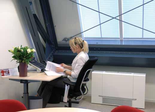
2 Fan coil units Comfortable indoor climate In buildings a pleasant work and living environment are, to a large degree, determined by the quality of the indoor climate. comfortable climate in a room will be noticed by staff and visitors. The iddle DECO fan coil unit gives you optimum control of the indoor climate by heating, cooling and/or ventilating the room. High quality climate The DECO proves that a comfortable living climate at a low noise level can be achieved. The unit is positioned in the room in such a way that the discharged air stream is distributed evenly across the room without causing a nuisance to the people in it. The Sint-Janslyceum school in s Hertogenbosch uses free-hanging Stylish models. Individual control People like to have control of the climate in their working environments. Everyone has their own preference for air temperature and quality. iddle fan coil units anticipate the need to control the climate per room. Users may simply regulate the room temperature and the fresh air supply themselves. enefits model DECO High quality climate Low sound level Individual control Various controls Wide scope of application Directional heating and cooling Many models and colours Easy installation and maintenance Wide scope of application The iddle DECO fan coil units are suitable for use in refurbished or newly built offices, meeting rooms, hotels, schools, care centres, hospitals, server rooms and retail outlets. The DECO is available in a variety of styles and designs, making it suitable for a wide range of applications. The free-standing usiness model fits in very well with the interior of msterdambased NS Consultants. 2


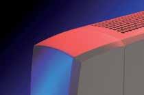
3 Optional accessories: various controls The DECO can incorporate an airside controller or a combined air- and waterside controller, either option having the corresponding easy-to-use control panel. The controller provides for efficient heating and cooling at the lowest possible noise level. The controller comes with a weekly timer and a room thermostat as a standard and can also be combined with a CO 2 -sensor to control the volume of fresh air (see page 7). Comfort where you need it djustable outlet grille The air is discharged directionally, max.: sideward, 10 backward and 30 forward. The iddle fan coil unit features an innovative adjustable discharge grille (Multi Vector Technology), which is made up of a number of stacked sheets with a hole pattern. Using this discharge grille, the direction of the air can be regulated. To cool a room, the air is blown into the room differently than when heating it. The grille enables the user to direct the air to or from the place where he or she is working, thus providing comfort where you need it. Easy to install and maintain ll fan coil units that have an airside or combined controller are delivered ready to use, so they are fast and easy to install. ll models come standard with a removable G2 filter. This filter prevents dust in the inlet air from settling on the battery or fans. The filter is hidden from view using a filter frame, which is easy to remove. The filter is fast and easy to clean with a vacuum cleaner. The filter can be withdrawn from the front of the unit. 3

: with curved plastic side covers 2.")


4 wide range of models People prefer climate control equipment that is unobtrusive and fits in with its surroundings. That s why iddle has devoted so much attention to the design of the DECO fan coil unit and has made it suitable for a wide range interior designs. Model with casing Ceiling model (usiness) This model is available either as a wall model (F) or as a ceiling model (C) and can be freely standing or suspended. The next units are available: 1. Stylish model (S): with curved plastic side covers 2. usiness model (): with straight metal side covers Recessed model The recessed model (R) is easy to integrate into the wall (F) or ceiling void (C). Standard colour combinations Recessed floor model Fan coil units with casing are available in two colours. Next to the conventional white colour, the unit is available in the colour titanium. Unless the customer requests a specific colour, the unit comes standard in white. Other colours are of course available at an extra charge. Titanium (usiness) White (usiness) Casing Filter frame Stylish (S) RL 9016 = white RL 9006 = white aluminium usiness () Polydrox = titanium Polydrox = titanium RL 9016 = white RL 9006 = wit aluminium 4
 Water connections R = right L = left HE = electrical connection on the left side.")
5 Typecode DECO 75-H1C3-R-FS12 Unit size 50 = m 3 /h 75 = m 3 /h 100 = m 3 /h 125 = m 3 /h 150 = m 3 /h Coil type H1, H2, H4 = Water heating C2, C3, C4 = Water cooling H1C3 = Water heating and - cooling HE = electric heating (1,2,3,4 = number of rows) Water connections R = right L = left HE = electrical connection on the left side. Model type FS = floor model: stylish F = floor model: business CS = ceiling model: stylish C = ceiling model: business FR = recessed Floor model CR = recessed ceiling model 2-12 = see figure 1: model types Many options asic models The fan coil unit is available in 5 unit sizes: DECO 50, DECO 75, DECO 100, DECO 125 and DECO 150. The air flow rates of these types range from m³/h. Model DECO can heat, cool or ventilate the room. The unit is available in different models (see figure 1). Figuur 1: model types Free-standing Floor model (FS or F) Free-hanging Ceiling model (CS or C) Recessed Floor model (FR) Recessed Ceiling model (CR) FS2 F2 CS2 C2 Recirculation Ventilation Recirculation/Ventilation F4 CS6 C6 CS 8 C8 CS10 C10 CS12 C12 CR2 CR4 CR6 CR8 CR10 CR12 * ll models are available as top discharge types. Only the recessed model has the possibility of a discharge plenum for front discharge. FS6 F6 FS8 F8 FS10 F10 FS12 F12 FR2 FR4 FR6 FR8 FR10 FR12 = inspection side = air direction Floor model (Stylish) 5
 condensate tray (only in models with cooling mode) Recessed units come with: removable air filter frost-protection device (only")
 ventilation module for coupling to an exhaust fan CO 2 sensor Wall grille lso the following accessories are")
6 Standard delivery Units with casing come with: adjustable discharge grille removable air filter integrated condensate draining pump (only in ceiling model with cooling mode) integrated frost-protection device and damper control (only in ventilation model) condensate tray (only in models with cooling mode) Recessed units come with: removable air filter frost-protection device (only in ventilation model) condensate tray (only in models with cooling mode) djustable discharge grille ccessories The following control accessories are available (see page 7): air side controller air- and waterside controller control panel CO 2 sensor low-voltage cables (different lengths) ventilation module for coupling to an exhaust fan CO 2 sensor Wall grille lso the following accessories are available (see page 23-27): sound - damping air inlet section wall sleeve wall grate roof cap discharge plenum for recessed models flexible connection sleeves with or without duct connecting flange adjustable discharge grille wall and ceiling grilles condensate draining pump (standard in encased ceiling model with cooling mode, optional in floor model) iddle and customer may agree on custom alterations or modifications to the unit. Weights of various models The weights of the various fan coil models are represented below (in kg). Model Type DECO 50 DECO 75 DECO 100 DECO 125 DECO 150 With casing recirculation stylish ventilation (type FS and CS) recirculation/ventilation With casing recirculation business ventilation (type F and C) recirculation/ventilation Recessed recirculation (type FR and CR) ventilation recirculation/ventilation
: The fan coil unit (only the recirculation model) is provided with a transformer and is wired in a fixed speed. 2.")


7 Control options Model DECO is available with three types of control, in order to make it suitable for every project. 1. asic (without control): The fan coil unit (only the recirculation model) is provided with a transformer and is wired in a fixed speed. 2. irside control This plug & play controller regulates the fan speed (3 speeds) to achieve the desired room temperature. 3. Combined air- and waterside controller This plug & play controller regulates both the fan speed and the discharge air temperature to achieve the desired room temperature. The ventilation unit is delivered with the combined controller. Controller with LCD display Waterside connection (H1C3) The control panel has various soft-touch keys and a clear LCD display. The desired room temperature can be set using the control panel, after which you can choose to have the controller regulate the climate either automatically or using one of the three fan speeds. Next to this functionality, the control panel features an integrated weekly timer, which can be used to switch the unit automatically on and off each day of the week. The keys of the control panel can be blocked using a key lock to prevent unwanted use. One single control panel allows the user to interconnect and operate a maximum of ten units. The maximum length of the control cables within a control system is 100 metres. The control panel offers menus for different purposes, including operation, installation and service menus as well as a menu for setting the weekly timer. utomatic or manual operation The control panel allows the user to select either automatic or manual operation of the DECO. The control panel is inclusive room thermostat. Weekly timer The DECO comes standard with a weekly timer, which allows the user to automatically switch the unit on and off per day of the week. CO 2 sensor The ventilation units can be equipped with a sensor to read the CO 2 level in the room. The sensor ensures that the CO 2 value preset in the control panel is maintained by automatically increasing or reducing the supply of fresh air. Integrated frost protection and air valve control The ventilation units have a controller-integrated frost protection thermostat and air valve control. The frost protection reduces the risk of the battery freezing (preset at 5 C). In the event of a power interruption or failure, the air valve automatically switches to the recirculation mode. Plug & play Ready to use Units with an airside or combined controller are delivered ready to use. The power cable (1.5 m), which has a moulded-on, earthed plug, is connected to the terminal box in the side of the unit. Via the connector plate and the interfaces in the terminal box, components such as slave units, control panel and in- and outputs can be connected to the PC. 7
8 Technical data DECO 50 Installation data electric supply V ; ph ; Hz 230 ; 1 ; 50 max. running current 0.35 max. consumed power W 90 General selection data speed tapping voltage V power consumption, fans input power, fans W air displacement m³/h sound level d() Heating H1 LPHW 80/60 C H2 LPHW 80/60 C H4 LPHW 50/30 C speed air displacement m³/h air inlet temperature ºC heating capacity kw discharge temperature ºC water flow rate l/h water pressure loss kpa air inlet temperature ºC heating capacity kw discharge temperature ºC water flow rate l/h water pressure loss kpa air inlet temperature ºC heating capacity kw discharge temperature ºC water flow rate l/h water pressure loss kpa air inlet temperature ºC heating capacity kw discharge temperature ºC water flow rate l/h water pressure loss kpa Cooling C2 LPCW 6/12ºC C3 LPCW 6/12ºC C4 LPCW 6/12ºC speed air displacement m³/h air inlet temperature ºC relative humidity % cooling capacity total kw cooling capacity sensible kw air outlet temperature ºC water flow rate l/h water pressure loss kpa * The control system limits the air discharge temperature to 50 C. This limitation is not included in the selection data. ** Water pressure loss, exclusive three- or two- way valve. For sft-values of three- or two-way valve, see page 22.
9 Technical data DECO 75 Installation data electric supply V ; ph ; Hz 230 ; 1 ; 50 max. running current 0.82 max. consumed power W 180 General selection data speed tapping voltage V power consumption, fans input power, fans W air displacement m³/h sound level d() Heating H1 LPHW 80/60 C H2 LPHW 80/60 C H4 LPHW 50/30 C speed air displacement m³/h air inlet temperature ºC heating capacity kw discharge temperature ºC water flow rate l/h water pressure loss kpa air inlet temperature ºC heating capacity kw discharge temperature ºC water flow rate l/h water pressure loss kpa air inlet temperature ºC heating capacity kw discharge temperature ºC water flow rate l/h water pressure loss kpa air inlet temperature ºC heating capacity kw discharge temperature ºC water flow rate l/h water pressure loss kpa Cooling C2 LPCW 6/12ºC C3 LPCW 6/12ºC C4 LPCW 6/12ºC speed air displacement m³/h air inlet temperature ºC relative humidity % cooling capacity total kw cooling capacity sensible kw air outlet temperature ºC water flow rate l/h water pressure loss kpa * The control system limits the air discharge temperature to 50 C. This limitation is not included in the selection data. ** Water pressure loss, exclusive three- or two- way valve. For sft-values of three- or two-way valve, see page 22. 9
10 Technical data DECO 100 Installation data electric supply V ; ph ; Hz 230 ; 1 ; 50 max. running current 0.82 max. consumed power W 180 General selection data speed tapping voltage V power consumption, fans input power, fans W air displacement m³/h sound level d() Heating H1 LPHW 80/60 C H2 LPHW 80/60 C H4 LPHW 50/30 C speed air displacement m³/h air inlet temperature ºC heating capacity kw discharge temperature ºC water flow rate l/h water pressure loss kpa air inlet temperature ºC heating capacity kw discharge temperature ºC water flow rate l/h water pressure loss kpa air inlet temperature ºC heating capacity kw discharge temperature ºC water flow rate l/h water pressure loss kpa air inlet temperature ºC heating capacity kw discharge temperature ºC water flow rate l/h water pressure loss kpa Cooling C2 LPCW 6/12ºC C3 LPCW 6/12ºC C4 LPCW 6/12ºC speed air displacement m³/h air inlet temperature ºC relative humidity % cooling capacity total kw cooling capacity sensible kw air outlet temperature ºC water flow rate l/h water pressure loss kpa * The control system limits the air discharge temperature to 50 C. This limitation is not included in the selection data. ** Water pressure loss, exclusive three- or two- way valve. For sft-values of three- or two-way valve, see page 22.
11 Technical data DECO 125 Installation data electric supply V ; ph ; Hz 230 ; 1 ; 50 max. running current 1.2 max. consumed power W 270 General selection data speed tapping voltage V power consumption, fans input power, fans W air displacement m³/h sound level d() Heating H1 LPHW 80/60 C H2 LPHW 80/60 C H4 LPHW 50/30 C speed air displacement m³/h air inlet temperature ºC heating capacity kw discharge temperature ºC water flow rate l/h water pressure loss kpa air inlet temperature ºC heating capacity kw discharge temperature ºC water flow rate l/h water pressure loss kpa air inlet temperature ºC heating capacity kw discharge temperature ºC water flow rate l/h water pressure loss kpa air inlet temperature ºC heating capacity kw discharge temperature ºC water flow rate l/h water pressure loss kpa Cooling C2 LPCW 6/12ºC C3 LPCW 6/12ºC C4 LPCW 6/12ºC speed air displacement m³/h air inlet temperature ºC relative humidity % cooling capacity total kw cooling capacity sensible kw air outlet temperature ºC water flow rate l/h water pressure loss kpa * The control system limits the air discharge temperature to 50 C. This limitation is not included in the selection data. ** Water pressure loss, exclusive three- or two- way valve. For sft-values of three- or two-way valve, see page
12 Technical data DECO 150 Installation data electric supply V ; ph ; Hz 230 ; 1 ; 50 max. running current 1.2 max. consumed power W 270 General selection data speed tapping voltage V power consumption, fans input power, fans W air displacement m³/h sound level d() Heating H1 LPHW 80/60 C H2 LPHW 80/60 C H4 LPHW 50/30 C speed air displacement m³/h air inlet temperature ºC heating capacity kw discharge temperature ºC water flow rate l/h water pressure loss kpa air inlet temperature ºC heating capacity kw discharge temperature ºC water flow rate l/h water pressure loss kpa air inlet temperature ºC heating capacity kw discharge temperature ºC water flow rate l/h water pressure loss kpa air inlet temperature ºC heating capacity kw discharge temperature ºC water flow rate l/h water pressure loss kpa Cooling C2 LPCW 6/12ºC C3 LPCW 6/12ºC C4 LPCW 6/12ºC speed air displacement m³/h air inlet temperature ºC relative humidity % cooling capacity total kw cooling capacity sensible kw air outlet temperature ºC water flow rate l/h water pressure loss kpa * The control system limits the air discharge temperature to 50 C. This limitation is not included in the selection data. ** Water pressure loss, exclusive three- or two- way valve. For sft-values of three- or two-way valve, see page 22.
13 Technical data DECO HE Installation data DECO 50 DECO 100 DECO 150 electric supply 400 V; 3 ph; 50 Hz 400 V; 3 ph; 50 Hz 400 V; 3 ph; 50 Hz max. running current max. consumed power kw heating* * With electric heating, the heating capacity is 5% lower than the installed power. General selection data DECO 50 DECO 100 DECO 150 speed tapping voltage V power consumption, fans input power, fans W air displacement m 3 /h sound level d() Electrical heating DECO 50 DECO 100 DECO 150 HE 400 V HE 400 V HE 400 V Speed air displacement m³/h available heating cap. 1 kw max. power consumption per phase air inlet temperature ºC discharge temperature ºC real heating capacity kw air inlet temperature ºC discharge temperature ºC real heating capacity kw air inlet temperature ºC discharge temperature ºC real heating capacity kw air inlet temperature ºC discharge temperature ºC real heating capacity kw t some fan speeds, the available heating capacity may be higher than the real heating capacity, as the control system limits the outlet air temperature tot 50 C. * The DECO 75 and DECO 125 are not available as electrically heated units. 13
14 Explanation The correction coefficients are for the capacities listed in the tables on page 8 to 12. They give an indication of the capacity at deviating water temperatures and air conditions. For exact data, please seek the advice of a iddle employee. Correction coefficients for heating capacities of the battery types H1 and H2 Correction coefficients for heating capacity of the battery type H4 Explanation of technical data Correction coefficients- heating capacity The heating capacities for the coil types H1 and H2 listed in the tables on pages 8 to 12 are based on a water temperature range of 80/60 C. The heating capacities for the coil type H4 are based on a water temperature range of 50/30 C. If water temperatures differ, the heating capacity is to be multiplied by the coefficients from the below tables. These coefficients are applicable to the heating capacities from the tables on pages 8 to 12 at an inlet air temperature of C. The first table lists the correction coefficients for the coil types H1 and H2. The correction coefficients for the coil type H4 are listed in the second table. H1/H2 ir inlet temperature -10 ºC 0 ºC 10 ºC ºC 90/70 ºC /60 ºC /50 ºC /40 ºC /30 ºC H4 90/70 ºC /60 ºC /50 ºC /40 ºC /30 ºC Correction coefficients - cooling capacity The cooling capacities for the coil types C2, C3 and C4 listed in the tables on pages 8 to 12 are based on a water temperature range of 6/12 C and on an inlet air temperature of 23 C at 50% R.H. If water temperatures and inlet air conditions differ, the cooling capacity is to be multiplied by coefficients from the table on page
15 Correction factors cooling capacity coil types C2, C3 and C4. Explanation of technical data C2, C3 and C4 LPCW ir inlet Relative Humidity temp. 40% R.H. 48% R.H. 60% R.H. Q t Q v Q t Q v Q t Q v 6/12 C 22 C C C C /16 C 22 C C C C /18 C 22 C C C C Q t = total cooling capacity Q v = sensible cooling capacity Water flow rate m w = water flow rate [l/h] Q = capacity [kw] (page 14) ρ w = density of water [kg/l] C pw = specific heat of water (= 4.18) [kj/kg C] T w = temperature difference water [ C] The water flow rates listed in the tables on pages 8 to 12 are based on a water temperature range of 80/60 C, 50/30 C or 6/12 C. If water flow rates differ from those listed in the tables on pages 8 to 12, the water flow rate may be roughly calculated using the opposite formula. efore doing so, the heating capacity must first be recalculated (see page 14). m w = Q ρ w C pw T w 3600 [ l/h] Water pressure loss p w1 = water pressure loss, table values [kp] p w2 = water pressure loss [kp] m w1 = water flow rate, table values [l/h] m w2 = water flow rate calculated using formula [l/h] Il water temperatures differ from those listed in the tables on pages 8 to 12, then the water pressure loss may be roughly calculated using the formula below. To do so, the water flow rate must first be calculated (see above). p w2 = p w1 m ( w2 ) 2 m w1 [kpa] 15
16 Explanation of Technical data Sound In the tables on pages 8 to 13, a sound level in the reverberation field is listed for all six speeds. These sound level values are based on the use of one fan coil unit in a reference room. Unit size Reference room DECO m 3 DECO m 3 DECO m 3 DECO m 3 DECO m 3 Reference room For each type of fan coil unit, a room has been taken for expressing the noise level. The reference room (Vo) is chosen dependent on the size of the unit, such that the air circulation ratio in the room is equal to 2 at fan speed 4. The reference room is stated in the opposite table. s many offices have sound-absorbing ceilings, an average reverberation time of 0.5 second has been assumed. Deviating room and multiple units Lp = sound pressure [d()] T = reverberation value in deviating room [s] T 0 = reverberation value is 0.5 s V = volume of deviating room [m 3 ] V 0 = volume reference room [m 3 ] (see table) n = number of units If a unit is used in a deviating room or if multiple units are used in a single room, the sound level must be recalculated. This can be done using the below formula, whereby the relevant table value can be retrieved from the tables on pages 8 to 13 (general selection data per speed). Sample calculation T V ( ( ) ( ) ) T 0 Lp = table value + 10 log -10 log +10 log (n) [d()] V 0 Wanted: the noise level in the reverberation field if three DECO 75 fan coil units are used at speed 3 in a room featuring a reverberation time of 0.6 second and a volume of 600 m log -10 log +10 log (n) = 34 + ( ) = 35,9 d() ( ( ) ( ) ) 16
17 Explanation of technical data Overview of sound data Unit size Sound pres- Sound power level** sure level* in d() Per octave band in the medium frequency in d (ref 1 x W) in d() Type Speed Lp 63 Hz 125 Hz 250 Hz 500 Hz 1000 Hz 00 Hz 4000 Hz 8000 Hz Lw DECO DECO DECO DECO DECO * The noise levels are based on the reverberation field in a reference room (see page 16). ** The value <0 indicates that the relevant value is below the threshold of hearing. 17
18 Explanation of Technical data Sound-damping air inlet section To reduce the noise, a sound-damping air inlet section can be installed in units that feature outside-air inlet. The section reduces both the outside noise coming in, such as traffic noise, and the inside noise going out, such as bar noise. The inner side of the sound-damping inlet section is finished with a sound-absorbing open-cell foam coat. The sound damping values have been measured according to NEN 140 at the laboratory of the Groningen-based firm Van Dorsser V (The Netherlands). Damping value - sound power level [d] Mode D n *, referenced to 10 m 2 per octave band in the medium frequence Total 125 Hz 250 Hz 500 Hz 1000 Hz 00 Hz 4000 Hz LW Damper actuator in ventilation mode Damper actuator in recirculation mode * D n is damping valve Damping value, - sound level differential per octave Ventilation Recirculation 40 D n [d] Hz 250 Hz 500 Hz 1000 Hz 00 Hz 4000 Hz The values from the table below can be used for a simplified calculation. Damping value - sound power level [d()] Mode R,netto * DECO 50 DECO 75 DECO 100 DECO 125 DECO 150 Damper actuator in ventilation mode Damper actuator in recirculation mode wall duct [m 2 ] * R,netto is the sound reduction per type of sound-damping air inlet section. 18
19 Recirculation Ventilation Recirculation/ Ventilation Curved plastic Depicted model DECO 50-HIC3-R-FS10 side covers djustable discharge grille Curved plastic side covers djustable discharge grille djustable discharge grille Floor model, Floor model, Curved plastic side covers ceiling model also available ceiling model also available Floor model, ceiling model also available FS2 FS6 FS 8 CS2 CS6 CS 8 FS 12 FS10 Filter frame CS10 djustable discharge grille Floor model, ceiling model also available Filter frame CS 12 Filter frame See page 5, figure 1 = inspection side Inlet grille 41 Inlet grilleinlet grille Removable to lead lines through Inlet grille Removable to lead lines through Removable to lead lines through Removable to lead lines through Filter frame = air direction Unit size DECO 50 DECO 75 DECO 100 DECO 125 DECO djusting foot djustingfoot djusting foot 280 djusting foot * 5-* * * 1 Curved plastic side covers Dimensional sketches of stylish model (S) Notes: ll dimensions in mm. * djusting size for adjusting feet. Only the floor model comes with adjusting feet. 19
20 Straight Straight metal metal side side covers covers Dimensional sketches of business model () djustable djustable discharge discharge grille grille Depicted model DECO 50-HIC3-R-F10 Floor Floor model, model, ceiling ceiling model model also also available available Recircltaion Ventilation Recirculation/ Ventilation Straight metal side covers F4 F2 C2 F6 C6 See page 5, figure 1 = inspection side djustable discharge grille Filter Filter frame frame F8 F10 F12 C8 C10 C12 Floor model, ceiling model also available = air direction Filter frame Inlet Inlet grille grille Removable Removable to to lead lead lines lines through through Inlet grille 41 Removable to lead lines through ** 507** ** Unit size DECO 50 DECO 75 DECO 100 DECO 125 DECO 150 djusting djusting foot foot * * 5-* F F4 F4 djusting foot Notes: ll dimensions in mm. * djusting size for adjusting feet. Only the floor model comes with adjusting feet. ** pplies only for encased floor model for recirculation, type F4. The minimum distance between floor and unit will then be 1 mm.
21 Floor model, Floor model, ceiling model also ceiling available model also available Dimensional sketches of Condensate discharge Condensate discharge recessed model (R) Depicted model DECO 50-HIC3-L-FR10 Connector plate Connector plate Recirculation Ventilation Recirculation/ Ventilation Floor model, ceiling model also available Control system C s FR2 FR4 FR6 FR8 FR10 FR12 Connector plate Condensate discharge CR2 CR4 CR6 CR8 CR10 CR12 See page 5, figure 1 = inspection side = air direction Valve motor Valve motor Control system Valve motor 179 C C Filter ** ** Filter ** C Filter Filter 612 CR4 FR4 Filter 612 CR4 FR4 5-* * Unit size C DECO Filter CR4 DECO FR DECO DECO DECO Notes: ll dimensions in mm. 253 * djusting size for adjusting feet. Only the floor model comes with adjusting feet. ** pplies only for recessed models for recirculation, types FR4 and CR4. The minimum distance between floor and unit will then be 1 mm *
22 Straight side covers (model usiness) Dimensional sketches Curved side covers water (model Stylish) connections Depicted model DECO 50-HIC3-L-FR6 Straight side covers (model usiness) Unit size DECO DECO DECO DECO DECO Curved side covers (model Stylish) Coil types C H1, H2, C2-129 C3-138 H4, C4-147 H1C Hole in bottom to lead lines through Key holes for mounting Return Hole in bottom to lead lines through Supply Key holes for mounting Heating for 4-pipes H1C Squeezed joints Return Cooling for 4-pipes H1C3 Cooling or heating for 2-pipes Supply Condensate discharge ø 15 mm Heating for 4-pipes H1C3 5-** 58*** *** 40 Squeezed C joints Unit size Coil types H1 H2 H4 C2 C3 C4 Kvs* DN Kvs* DN Kvs* DN Kvs* DN Kvs* DN Kvs* DN Condensate discharge ø 15 mm DECO DECO DECO /2.5 3/ /3.5 3/3.5 DECO /2.5 3/ /3.5 3/3.5 DECO / /2.5 3/3.5 Notes: ll dimensions in mm. With sizes and C, minor deviations of 5mm at the most may occur. * Kvs values for 3- and 2-way valves. Where values vary, the 3-way valve is mentioned first, followed by the 2-way valve. ** djusting size for adjusting feet. Only the floor model comes with adjusting feet. *** Size for H1-connection if H1C3 is used. - pipe diameter squeezed joint DN 15: 15 mm, DN : 22 mm. - pipe connection can be made to both the left- and the right-hand side of the unit. Cooling for 4-pipes H1C3 Cooling or hea for 2-pipes
23 Dimensional sketches of attenuated air inlet section 142xC 142xC Depicted DECO xC xC Unit size C DECO DECO DECO DECO DECO Notes: ll dimensions in mm. vailable for Ceiling and Wall models. Holes for mounting are situated at the back site of the unit (see page 22). 23
24 Dimensional sketches discharge section and plenum Discharge section* Material: zinc coated plate steel Depicted DECO 50-H1C3-L-FR C ir inlet and discharge plenum Material: zinc coated plate steel Unit size C DECO DECO DECO DECO DECO ø Discharge section ir inlet plenum for CR4/FR ø ø 0 ø 0 ir inlet plenum for FRC/CR4 Unit size Spouts C DECO DECO DECO DECO DECO Discharge plenum Unit size Spouts C DECO DECO DECO DECO DECO Notes: ll dimensions are in mm. * The discharge section is used in recessed models to switch from top discharge to front discharge. * The discharge section may be used with a flexible connection sleeve (see page 26) or a grille (page 26).
25 Dimensional sketches flexible connection sleeves Depicted DECO 50-H1C3-L-FR * * * C D Unit size C D DECO DECO DECO DECO DECO Remarks: ll dimensions in mm. Material: PVC-coated polyester tissue (bisonyl) * vailable with or without duct connection flange (made of zinc plated sheet steel). Connection sleeves are delivered unit-mounted. 25
26 6.5 djustable discharge grille Material: painted zinc plated sheet steel. C C 6.5 Dimensional sketches of wall and ceiling grilles Depicted for model DECO 50 Fin grilles Material: natural-coloured, extruded, anodised aluminium, includes a fixing frame with recessed holes. vailable in three types: Double adjustable grille Unit size C DECO DECO DECO DECO DECO ll dimensions are in mm. Unit size DECO DECO DECO DECO DECO ll dimensions are in mm Single adjustable grille Unit size DECO DECO DECO DECO DECO ll dimensions are in mm. 3. Fixed grille Unit size DECO DECO DECO DECO DECO ll dimensions are in mm Notes: These grilles can be used for both in- and outlet sides. On the outlet side, 6 the grille is mounted onto the unit using a flange. 26
27 Removable cover Removable cover Wire grid Wire grid Dimensional sketches wall and roof ducts Depicted model DECO 50 Roof cap and roof duct Material: 1.5 mm aluminium sheet C C 530 Removable cover Wire grid Threaded Threaded connection, connection, to be drilled to be drilled after removal after removal of rain cap of rain cap C rchitectural rchitectural 139 roof upstand roof upstand finished with finished with roofing. roofing Threaded connection, to be drilled after removal Wall duct and wall grate of rain cap Material: zinc coated plate steel Unit Size 530 C DECO DECO DECO DECO DECO ll dimensions in mm Top view rchitectural 139 roof upstand 46 finished with 0 roofing. 6 C Wall grate D E Wall grate Wall duct Wall duct Wall duct Outside of Inside Unit size C D E DECO DECO DECO DECO DECO Side view
28 Specifications Casing The casing is made up of a front plate and side covers, and is available in different colours. The front plate is made of zinc plated sheeting with a hard epoxy polyester powder coating. The round sides are made of plastic, the straight sides of zinc plated sheeting. The structural parts are made of galvanised sheeting with extra strengthening to minimise distortion and vibrations. Where necessary, the models are insulated to reduce sound and heat transmission. Fan/Motor assembly One or more (depending on type) dual-inlet, vibration-free suspended centrifugal fans, driven by a rotor motor on ball bearings. The fan casing and the impeller are made of zinc coated plate steel. The motor is manufactured according to DIN 40050, Protection Class IP44, and Insulation Class. The motors have, as a standard, thermal contacts in the windings. These thermal contacts will break the circuit when the maximum permissible motor temperature is exceeded. Heating (LPHW) / Cooling (LPCW) coils The high-efficiency coils are made up of 3 / 8 " copper pipes and aluminium fins. The coils are available with 2 or 4 rows of pipes. The maximum operating pressure is 6 bar at 90 C. Then, a maximum operating pressure of 10 bar at 90 C applies. The permissible difference (Δp/kP) is as follows: Kvs value 2-way valve 3-way valve ISO 9001 ISO Electric heating coil The electric heating coil is made up of aluminium fins. The power is controlled by the electronic control unit, which is fitted with an overload protection system. When the unit is switched off, the fans will continue to rotate until the fins have cooled off sufficiently. Subject to change Southern Europe and MEN iddle 21 allée des Vendanges Croissy-eaubourg France T +33 (0) F +33 (0) E contact@biddle.ae I DECO.FR-en(ae) PDF
Fan coil units Model DECO. - heating - cooling - ventilation
 Fan coil units Model DEO - heating - cooling - ventilation Fan coil units omfortable indoor climate In buildings, pleasant working and living conditions are to a large degree determined by the indoor climate.
Modular fan coil unit model PS
 Modular fan coil unit model PS Flexible air conditioning system Modular fan coil units For the perfect indoor climate A pleasant indoor environment is largely determined by the room's climate. People often
Multi directional heating. Air heaters Model NOZ
 Multi directional heating Air heaters Model NOZ Air heaters The ideal heat source for large buildings Air heaters are used for the heating and ventilation of large industrial buildings. New industrial
COMFORT AIR CURTAIN. SensAir
 COMFORT AIR CURTAIN SensAir SensAir comfort air curtain Revolutionary climate separation The SensAir comfort air curtain sets a new standard in the field of climate separation. The highest level of comfort
COMFORT AIR CURTAIN. SensAir
 COMFORT AIR CURTAIN SensAir SensAir comfort air curtain A new wave in climate separation SensAir air curtains are the ideal solution for retailers and other end-users to combat the issue of climate separation
COMFORT AIR CURTAIN. SensAir
 COMFORT AIR CURTAIN SensAir SensAir comfort air curtain A new wave in climate separation SensAir air curtains are the ideal solution for retailers and other end-users to combat the issue of climate separation
UTA STANDARD. Ductable units. Range. Air handling unit with high available static pressure. NEW Eco-Design Filter. V3000 control Fresh air management
 Ductable units NEW Eco-Design Filter Air handling unit with high available static pressure V3000 control Fresh air management The range of air handling units is designed for suspended ceiling heating and
Highline 260i EC Waterside Fan Coil Unit
 Features: Electronically Commutated (EC) fan motor Specific Fan Power of 0.16 to 0.34 at NR Insignificant fan heat gain Designed to operate below NR at External Static Pressures of up to 50Pa Variable
KLIMA Active Chilled Beams
 KLIMA 2 600 Active Chilled Beams 0 Index Subject Page Index 1 Introduction 2 General description 3-4 Product features 5-6 Dimensions 7 Performance data 8-11 Selection example 12 Guide specifications 13
GigaBox centrifugal fans Product specific information
 GigaBox centrifugal fans Product specific information GigaBox and accessories Wall bracket GB-WK (ccessories) Outdoor cover hood GB-WSD (ccessories) Included in delivery: a) Flexible sleeve b) Outlet spigot,
CENTRIFUGAL FAN COIL UNIT VCE
 CENTRIFUGAL FAN COIL UNIT VCE 0,51 kw 11,00 kw 0,85 kw 23,75 kw 129 m 3 /h 2003 m 3 /h VCE DESIGN QUALITY COMFORTRELIABILITY 3VERSION12 SIZE DESIGN VCEx0 vertical with cabinet Air intake: bottom vertical
Fans Air Handling Units Air Distribution Products Fire Safety Air Curtains and Heating Products Water terminals SYSCOIL. Centrifugal fan coil units
 Fans Air Handling Units Air Distribution Products Fire Safety Air Curtains and Heating Products Water terminals SYSCOIL Centrifugal fan coil units SYSCOIL Fan coil units Compact, slim fan coil units. Available
Fan Coil Units. Technical Data ECDEN FWL-DT/DF
 Fan Coil Units Technical Data ECDEN10-400 FWL-DT/DF Fan Coil Units Technical Data ECDEN10-400 FWL-DT/DF TABLE OF CONTENTS FWL-DT/DF 1 Features.............................................................
MAJOR 2 NCH. Ductable units. High pressure and high capacity ductable units RANGE NCH Y NCH NCH I COADIS COMBI. Motor optional
 Y + U I COADIS COMBI High pressure and high ductable units Motor optional is a non independent air conditioning terminal unit for heating and cooling offices and hotels. With reduced dimensions and designed
CMTE. Tangential Fan Coil Series with Electronic Controlled Motor
 Tangential Fan Coil Series with Electronic Controlled Motor Designed by Very Low Electric Energy Consumption High Efficiency Extremely Low Noise Level Infra Red Remote Control Step-less Fan Speed Control
Features: Available in horizontal and vertical units
 Features: Available in horizontal and vertical units Ideal for Shopping Malls, Retail Outlets and Office Receptions Can be supplied in a large range of colours and finishes Numerous mounting bracket arrangements
Ductable Modular Fan Coil Unit VPX. Technical Brochure TM VPX-W.2GB Date : May 2004 Supersedes : TM VPX-W.1GB/08.03
 Ductable Modular Fan Coil Unit VPX Technical Brochure TM VPX-W.2GB Date : May 2004 Supersedes : TM VPX-W.1GB/08.03 Design Features Presentation The VPX fan coil unit has been specially designed to meet
Fan Coil Units. Technical Data. Conceiled ceiling unit ECDEN FWB-BT
 Fan Coil Units Technical Data Conceiled ceiling unit ECDEN10-400 FWB-BT Fan Coil Units Technical Data Conceiled ceiling unit ECDEN10-400 FWB-BT TABLE OF CONTENTS FWB-BT 1 Features.............................................................
AHPHX Compact. Heat Recovery Air Handling Unit. BIM & REVIT Engineering Solutions. Acoustic Testing Laboratory College of Science & Technology
 HANDLERS LTD AHPHX Compact Heat Recovery Air Handling Unit 1262 Acoustic Testing Laboratory College of Science & Technology BIM & REVIT Engineering Solutions The Company Air Handlers has been trading since
Centriflow Plus EC. Technical data
 Technical data Centriflow Plus CTLOGUE Contents General description...3 General survey chart...4 Design description Fan Impeller...5 Inlet cone and supporting frame...5 EC motor...5 ir flow sensor...6
Chiller, Close control and Water terminals. Air Conditioning. Light Commercial, Commercial and Industrial
 Chiller, Close control and Water terminals Air Conditioning Light Commercial, Commercial and Industrial Water Terminals 133 Water Terminals Fan coils & Cassette Centrifugal fan-coil SYSCOIL Ductable fan-coil
AHTW Compact. Heat Recovery Air Handling Unit. BIM & REVIT Engineering Solutions. Acoustic Testing Laboratory College of Science & Technology
 HANDLERS LTD AHTW Compact Heat Recovery Air Handling Unit 1262 Acoustic Testing Laboratory College of Science & Technology BIM & REVIT Engineering Solutions The Company Air Handlers has been trading since
Modular Air Handling. Up to 3,500 Litres / sec. Low profile & Plant room application. Draft. Version. Second Edition A-. AirDesign 2015 AirDesign 2016
 Modular Air Handling U n i t R a n g e Up to 3,500 Litres / sec Low profile & Plant room application AirDesign 2015 AirDesign 2016 Second Edition Draft Version A-. Air Design is a proud Australian based
PVHRU Max Quiet. Engineering Solutions. Packaged Void Heat Reclaim Unit. Acoustic Testing Laboratory College of Science & Technology
 AIR HANDLERS LTD PVHRU Max Quiet Packaged Void Heat Reclaim Unit 1262 Acoustic Testing Laboratory College of Science & Technology Engineering Solutions The Company Air Handlers has been trading since May
BACKWARD CURVE CENTRIFUGAL FANS KABB / KABT Series
 Cabinet fans manufactured from galvanised steel sheet with double thickness side panels lined with 17 mm thickness of fireproof fibreglass acoustic insulation (M0). Circular duct connection flange on the
Duct Fans - ESTOC EC Range. Estoc EC Features. Electrical Supply. Sizes 355, 400, 450, 500, 560 and 630. Product Code
 Tubes and ox Fans Duct Fans - ESTOC EC Range Features Sizes from 55 to 6 mm diameter ir flow 19, m /h (4. m /s) Static pressures up to 84 Pa Maximum temperature up to 6 C Controllable external rotor motors
Swimming Pool CSR2 Heat Recovery Equipment
 Swimming Pool CSR2 Heat Recovery Equipment LIFETIME WARRANTY OVER 90% HEAT RECOVERY LOW CARBON British manufacturing at its best EcoAir Box is a trademark of IPT +44 (01527) 492770 www.ecoairbox.co.uk
Features: Concealed installation. Compact design. Available in electric, LPHW or ambient.
 Features: Concealed installation. Compact design. Available in electric, LPHW or ambient. Grille can be supplied in a large range of colours. Energy saving controls option available. Application The Diffusion
BRIZA 22 HYBRID HEATING & COOLING
 BRIZA 22 HYBRID HEATING & COOLING Built-in Ceiling: BABC/BT BABC/FT Built-in Wall: BABW/BT BABW/BF BABW/FT BABW/FF INFO SHEET BRIZA 22 HYBRID, COMPACT FANCOIL With EC Greentech EBM-PAPST technology Europe
Fan coil units MAJOR 2 CV/CH
 CH 41 D CV 1 D MAJOR 2: Design and performance HEE impeller for increased performance Motor optional MAJOR 2 is a non-independant chilled and/or hot water supplied air conditioning Comfort unit for the
Engineering Data Manual. New : available with EC motor. High Static Pressure Ductable Fan Coil Unit. Models 07 to to 4650 m 3 /h
 Engineering Data Manual New : available with EC motor VH High Static Pressure Ductable Fan Coil Unit Models 07 to 27 800 to 4650 m 3 /h General Characteristics Presentation On model VH 07, coils have 4
Hydropac. Waterside Control Fan Coil Units For Horizontal and Vertical Applications. June Hydropac. Features
 June 2003 Hydropac Hydropac Waterside Control Fan Coil Units For Horizontal and Vertical Applications Features Flush panel extra rigid construction. Low noise levels. Eleven speed transformer. Full acoustic
NEW. Wall controls. YFCN Fan Coil Units. Technical Guide - for internal distribution only
 NEW Wall controls Fan Coil Units www.euroventcertification.com www.certiflash.com Technical Guide for internal distribution only CONTENTS Construction Page 4 s Page 5 Dimension, Weight, Water content Page
Versatility. Features. By installing the SILENT MV, you will never experience the disturbance of noisy ventilation again. Benefits
 Ultra quiet and low profile helicocentrifugal in-line fans suitable for a wide range of domestic and commercial applications. Fitted with sound absorbent insulation and manufactured with an adjustable
Chassis Access Fans Motors Speed Control Coils The Condensate Tray Insulation Spigots Controls Enclosure Control Valves Filters Rev A
 Chassis panelwork is all In House manufactured from nominally 1.2mm Galvanised steel. Where at all possible, flanges are formed inward facing to prevent exposure to bare metal edges. Sufficient forms and
Guide Specifications. General. Casing. Coil/Drain pan. Fan/Motor
 Guide Specifications General CR-A series ducted concealed chilled water fan coil units have an air flow range from 45 to 3060 cubic meters per hour with a capacity range from kw up to 9 kw. The CR-A series
The World Leading Air-conditioning Company
 The World Leading Air-conditioning Company Table of Contents DESCRIPTIONS Model Number Nomenclature Features & Benefits Physical Dimension Fan Performance Curve (4 Row) - 40LMA024 with AC Motor - 40LMA040
Centrifugal performance characteristics with axial flow pattern: RADAX VAR
 High pressure in-line mixed-flow fans RADAX VAR Centrifugal performance characteristics with axial flow pattern: RADAX VAR COMPACT PRESSURE-RESISTANT UNIVERSAL In their compact casing, the RADAX VAR impellers
^áêëçåâ=ìåáí=åççäéêë=qvoj^ pí~åç~êç=åççäéêë=ïáíü=pí~áåäéëë=píééä=íìäáåö
 ^áêëçåâ=ìåáí=åççäéêë= pí~åç~êç=åççäéêë=ïáíü=pí~áåäéëë=píééä=íìäáåö O `çåíéåíë= page Model indication................................ 2 Eurovent...................................... 2 Capacities.....................................
Fan coil unit NBS 100/150
 Fan coil unit /150 Ferdinand Schad KG Steigstraße 25-27 D-78600 Kolbingen Telephone +49 (0) 74 63-980 - 0 Fax +49 (0) 74 63-980 - 200 info@schako.de www.schako.de Contents Description...3 Advantages...3
ERP 2015 Regulation (EU) Compliant with. No. 327/2011. Cert. n Heating. Meltemi Door Curtains
 Compliant with. No. 327/2011. Cert. n Heating. Meltemi Door Curtains") Compliant with ERP 015 Regulation (EU) No. 7/011 Cert. n 0545 Heating Door Curtains The range of SBIN door curtains offers imum flexibility in the protection of doors and open access compartments. By connecting
Compliant with ERP 015 Regulation (EU) No. 7/011 Cert. n 0545 Heating Door Curtains The range of SBIN door curtains offers imum flexibility in the protection of doors and open access compartments. By connecting
Resolair 64 and 68. Comfort air conditioning unit with highly efficient regenerative heat storage packages. AIR VOLUME FLOW: 3,900 23,100 m³/h
 Comfort air conditioning unit with highly efficient regenerative heat storage packages 68 10 01 - simplified illustration Automatically selects the most economical operating mode! 64 and 68 AIR OLUME FLOW:
HIGH EFFICIENCY ROTARY WHEEL - HELPING TO SAVE ENERGY AND REDUCE CARBON EMISSIONS.
 XBOXER THERMAL WHEEL HEAT RECOVERY UNITS HIGH EFFICIENCY ROTARY WHEEL - HELPING TO SAVE ENERGY AND REDUCE CARBON EMISSIONS. 118 029 2085 8200 XBOXER THERMAL WHEEL BENEFITS HIGH EFFICIENCY Up to 85% efficient
TECHNICAL MANUAL ESTRO BLDC ESTRO BLDC FAN COILS - BRUSHLESS TECHNOLOGY. 1.5 kw kw
 GB TECHNICAL MANUAL ESTRO BLDC ESTRO BLDC FAN COILS - BRUSHLESS TECHNOLOGY 1.5 kw - 9.0 kw TABLE OF CONTENTS 1 Generalities... 3 2 Models and constructive components...4-5 3 Accessories available... 6
Chiller Close Control Water terminals SYSCASSETTE. Water cassette units
 Chiller Close Control Water terminals SYSCASSETTE Water cassette units SYSCASSETTE Water cassette Available accessories Available in 8 different sizes and 2 versions. Due to its square design these units
Küba SG industrial
 66 Küba Blue Line : Specific advantages The is a master of customisation. No matter how great the demand for power, the is the answer. Its versatility allows the Küba SG industrial to master the most complex
fåçìëíêá~ä=~áê=åççäéêë=qvo pí~åç~êç=åççäéêë=ïáíü=ëí~áåäéëë=ëíééä=íìäáåö
 fåçìëíêá~ä=~áê=åççäéêë= pí~åç~êç=åççäéêë=ïáíü=ëí~áåäéëë=ëíééä=íìäáåö O `çåíéåíë= page Model indication..................................2 Eurovent.......................................2 Capacities......................................2
OptimAir NF. Active Chilled Beam OptimAir NF. Nov
 OptimAir NF Active Chilled Beam OptimAir NF Functions The OptimAir active chilled beam is a two-way induction type air-conditioningunit that is designed for integrated installation, mounted directly in
SILENT MV Ultra Quiet In-line Fans
 Ultra Quiet In-line Fans 5 IP44 2 YEAR GUARANTEE Ultra quiet and low profile helicocentrifugal in-line fans suitable for a wide range of domestic and commercial applications. Fitted with sound absorbent
CENTRIFLOW 3D WITH EC MOTOR >> Technical catalogue
 CENTRIFLOW 3D Plug Fan WITH EC MOTOR >> Technical catalogue air comfort CentriFlow 3D 2 GMEC CentriFlow 3D - Technical Catalogue Contents GENERL Description and survey chart pplication... 3 General Survey
AHN 064 to 304 EHN/CHN 064 to 304
 u Horizontal Packaged and Split Air Conditioners AHN 64 to 34 EHN/CHN 64 to 34 6. to 29.2 kw 6.4 to 29.4 kw Engineering Data Manual EDM AECHN-A.1GB Date : June 28 Supersedes : None Technical Description
Total comfort control
 Total comfort control YORK ACTIVE CHILLED BEAM WITH PERFORATED RETURN DIFFUSER Table of contents Concept & Technology Air Distribution & Facade Orientation Product Features Dimensions Performance Data
HEAT-RECOVERY UNITS WITH ENTHALPY/ROTARY HEAT EXCHANGER TECHNICAL MANUAL
 UT REC - R HEAT-RECOVERY UNITS WITH ENTHALPY/ROTARY HEAT EXCHANGER TECHNICAL MANUAL 1 CONTENTS GENERAL FEATURES... 3 Scope of the unit... 3 Available configurations... 3 Description of the components...
Innovative, High Performance, Quiet Units.
 Fan Coil Units Innovative, High Performance, Quiet Units. Technical Brochure TM AQF-A.4GB Date : January 2006 Supersedes : TM AQF-A.3GB/04.04 Quality, efficiency and reliability, built into every unit...
Systempac. Fan Coil Unit / Acoustic Flex / Diffuser System Package. Systempac. January Features and Design Guide
 January 2002 Systempac Features and Design Guide Specifically Designed for Design and Build Projects. Complete package including Waterside Control Fan Coil Unit / Controls / Flexible Ducting / Plenum Box
Cert. n 0545 Carisma CRC Fan Coil Unit The Ultra Quiet Fan Coil TECHNICAL GUIDE
 Cert. n 0545 www.euroventcertification.com Carisma Fan Coil Unit The Ultra Quiet Fan Coil TECHNCAL GUDE Carisma CONTENTS Construction Page 4 s Page 5 Dimension, Weight, Water content Page 6 EUROENT certification
42AM. Air heaters. product selection. the best solution for heating large spaces. ensures buildings warm up ultra-fast
 product selection the best solution for heating large spaces ensures buildings warm up ultra-fast excellent diffusion via patented JET+ double deflection technology ir heaters 4M Translation of the original
Ceiling swirl diffusers
 X X testregistrierung Ceiling swirl diffusers Type Horizontal swirling air discharge Vertical air discharge Protective cage For high rooms, with adjustable air control blades Square ceiling swirl diffusers,
VENT Series CENTRIFUGAL IN-LINE FANS VENT. In-Line duct fans. Mounting foot
 CENTRIFUGAL IN-LINE FANS Series Range of in-line duct centrifugal fans, manufactured from high grade corrosion resistant pressed galvanised steel and supplied as standard with a pre-wired wiring junction
Product Catalogue ARMONIA Providing indoor climate comfort
 Product Catalogue ARMONIA Providing indoor climate comfort ARMONIA 1,3-11 kw Water cassette Main applications Light commercial buildings Offi ces Shops General description Why this choice? Silent operation
ULTRA LOW ENERGY. VHR Void Series W/I/s TOTAL SFP Typical. Made in the UK. VHR Void Mounted Heat Recovery Units VHR PERFORMANCE OVERVIEW:
 VHR Void Mounted Heat Recovery Units TM.72 W/I/s TOTAL SFP Typical General: Units shall be manufactured from high quality galvanized sheet steel with stainless steel drain trays, acoustic, non-hygroscopic
Ocelot vertical fan coil unit
 Ocelot vertical fan coil unit 250mm Deep vertical Waterside control Cased unit DUNHAM BUSH OCELOT VERTICAL CASED FAN COIL UNIT The Dunham Bush Ocelot fan coil unit is a fully cased vertical unit suitable
Everest XV. ErP. High Efficiency HRV Fan Unit READY
 High Efficiency HRV Fan Unit ErP READY Field of application Installation Advantages Description Range Technical details Aeraulic and electrical details Acoustic specifications Aldes Smart Control system
IN-LINE RECTANGULAR FANS IRB / IRBS IRB
 IN-LINE RECTANGULAR FANS IRB / IRBS IRB IN-LINE RECTANGULAR FANS IRB / IRBS IRB and IRBS are a compact series of centrifugal type exhaust and supply in-line duct fans for air conditioning systems. They
ACTIVENT System. Specifications. Product code example ACTA
 Activent is a ventilation system for supplying and distributing air. The system has been proven to function effectively in both small and large areas and is used in all types of premises ranging from offices
AKOR-HR NEW HIGH EFFICIENCY HEAT RECOVERY UNIT. Heat Recovery AKOR-HR. Easy maintenance. EN AKOR-HR 14/1/08 13:01 Página 599
 EN 599-604 AKOR-HR 14/1/08 13:01 Página 599 HIGH EFFICIENCY HEAT RECOVERY UNIT AKOR-HR NEW Heat Recovery unit with casing manufactured from expanded polypropylene. Outlet and inlet duct conectors Ø150.
Exhaust Fans CATALOGUE 2013 / 14
 Exhaust Fans CTLOGUE 2013 / 14 We are proud to introduce the first models of our new series ETMSTER. Our new design has successfully exceeded the excellent efficiency of the ETLINE series and we have improved
CCE - Adaptable active chilled beam for exposed installation. Halton CCE. Adaptable active chilled beam for exposed installation
 Halton CCE Adaptable active chilled beam for exposed installation Combined cooling, heating, and supply air unit for exposed installation Ideal solution for applications where good indoor environment,
MegaBox Product-specific information
 MegaBox Product-specific information Application Noise-encapsulating centrifugal fans with retractable motor impeller unit and motor located outside the air flow Suitable for rough operating conditions
CONFIGURABLE HIGH-EFFICIENCY HEAT RECOVERY UNITS CADB/T-HE PRO-REG Series
 False-ceiling models CADB/T-HE 4 to 33 Heat Recovery Compact heat recovery unit with high-efficiency (up to 93%) counter-flow heat exchanger, EUROVENT certified. The casing is made from plasticised galvanised
technical data air conditioning systems Round Flow Cassette FXFQ-P9VEB
 technical data Round Flow Cassette FXFQ-P9VEB air conditioning systems technical data Round Flow Cassette FXFQ-P9VEB air conditioning systems TABLE OF CONTENTS FXFQ-P9VEB 1 Specifications.......................................................
fåçìëíêá~ä=~áê=åççäéêë=qelo pí~åç~êç=åççäéêë=ïáíü=`ì=íìäáåö
 = pí~åç~êç=åççäéêë=ïáíü=`ì=íìäáåö O `çåíéåíë= page Model indication..................................2 Eurovent.......................................2 Capacities......................................2
Twin and Single Inline Fans. Offers a range of flexible installation and application options, including auto-changeover on the Twin range
 Twin and Single Inline Fans Offers a range of flexible installation and application options, including auto-changeover on the Twin range 2 Version 3.1 Breathing Buildings Inline Box Fans Demand Control
CENTRIFLOW 3D WITH AC MOTOR >> Technical catalouge
 CENTRIFLOW 3D plug fan WITH AC MOTOR >> Technical catalouge air comfort Centriflow 3D 2 GMEB CentriFlow 3D - Technical Catalouge Contents GENERAL Description and survey chart Application... 3 General Survey
BRIZA Super slim and powerful heating, cooling
 BRIZA 2018.EX BRIZA Super slim and powerful heating, cooling Briza is a climate unit with a dual personality: a Hybrid that provides comfortable heat in winter and refreshing cooling in summer. It provides
Carisma The Ultra Quiet Fan Coil
 Carisma The Ultra Quiet Fan Coil Air Conditioning Carisma / CRR Fan Coil Units Quality management systems SO 900 Cert. n 0545/4 www.euroventcertification.com www.certiflash.com CONTENTS Construction ()
Warning. Document ref: A October 2015
 Sentry Door Curtain Installation, Operation & Maintainance Instructions Dunham-Bush Ltd, Downley Road, Havant, Hampshire, P09 2JD Tel. 023 9247 7700 Email. info@dunham-bush.co.uk Document ref: 128-000-001-A
CornerAir. CornerAir. Active chilled beam
 Active chilled beam Description The active chilled beam is a one-way induction type air-conditioning unit that is designed for exposed installation, mounted directly under the ceiling against the corner.
technical sales guide - 60Hz Ducted Split Units HIGH AMBIENT OPERATION 52 UPTO
 technical sales guide - 60Hz Taurus R Ducted Split Units UPTO HIGH AMBIENT OPERATION 52 O C Page CONTENTS Nomenclature.. 2 Description. 3 Features.. 3 Product Data. 4 Condensing Unit Cooling Performance
IN-LINE DUCT FANS MIXVENT-TD Fan Systems
 IN-LINE DUCT FANS MIXVENT-TD Fan Systems NEW TD-EXTRACTOR KIT (see page 175) MIXVENT TD / MIXVENT TD-T MIXVENT TDx2 ACCESSORIES Description Range Construction The MIXVENT system has been designed to compliment
NR series. Circular CAV air volume control terminals with system powered mechanical regulator
 series Circular CAV air volume control terminals Table of contents Description Page Type designation 1 Technical data - General 2 - Specification 3 - Installation instruction 3 overview / dimensions 4-5
CENTRIFUGAL IN-LINE FANS VENT Series
 Range of in-line duct centrifugal fans, manufactured from high grade corrosion resistant pressed galvanised steel and supplied as standard with a prewired wiring junction box and a robust mounting foot.
BRIZA EC 12 HYBRID. World s slimmest fan coil HEATING AND COOLING
 World s slimmest fan coil wall and ceiling installation 2-or 4-Pipe system heating and / or cooling with or without enclosure easy installation 24VDC EC motor silent, powerful, economical, sustainable
SINGLE DUCT TERMINAL UNITS
 www.igcaire.com SINGLE DUCT TERMINAL UNITS Direct Digital Control, Pressure Independent FEATURES 22 Gauge Galvanized Steel Casing Construction with a 20 Gauge Casing Option that Provides Strength and Product
 air curtains CONTENTS THERMOSCREENS... 04 WHY FIT AN AIR CURTAIN?... 05 AIR CURTAIN SELECTION GUIDE... 06 THERMOSCREENS SELECTION OVERVIEW... 07 AIR VELOCITY DISTRIBUTION CHART... 08 ECOPOWER CONTROL...
42GW. Hydronic Cassette Fan Coil Units PRODUCT SELECTION DATA INSTALLATION, OPERATION AND MAINTENANCE INSTRUCTIONS EASY INSTALLATION
 PRODUCT SELECTION DATA EASY INSTALLATION INSTALLATION, OPERATION AND CENTRAL AIR DIFFUSION MAINTENANCE INSTRUCTIONS LOW ENERGY CONSUMPTION IMPROVED COMFORT ELEGANT AIR INLET GRILLE EXTREMELY QUIET OPERATION
Total cooling capacity kw Total heating capacity kw Features
 Room Fan Coils Idrofan Quality Management Systems 42N Total cooling capacity 0.75-6.35 kw Total heating capacity 0.60-9.50 kw The new generation 42N_S product range combines aesthetic and attractive design
DRAFT. Technical Data OPA Ducted Three Phase Packaged Air Conditioners. 47 kw 96 kw
 DRAFT Ducted Three Phase Packaged Air Conditioners Technical Data 96 Twin System Enables Staging Extra Long Life Epoxy Coated Outdoor Coil OPTION TZT-71 Controller & Digital Scroll Compressor for close
CODE MODEL 1RC9020 REC PRO 90 S RC9021 REC PRO 90 S RC9022 REC PRO 90 S RC9023 REC PRO 90 S
 REC PRO 9S High efficiency Heat Recovery Units Non residential applications EFFICIENCY 9% Comply with ErP Directive 125/29/CE and EU Regulation 1253/214. Classification: Non Residential Ventilation Unit
Swegon PACIFIC. Integrated climate beam
 Swegon Integrated climate beam www.eurovent-certification.com www.certiflash.com climate beam The is a high performance climate beam for installation in false ceilings. With high built-in flexibility,
VEX500 (Everest XH) High Efficiency Bidirectional Fan Unit
 High Efficiency Bidirectional Fan Unit") High Efficiency Bidirectional Fan Unit VEX5 (Everest XH) Field of application Installation Advantages Description Range Technical details Aeraulic and electrical details Acoustic specifications Aldes Smart
High Efficiency Bidirectional Fan Unit VEX5 (Everest XH) Field of application Installation Advantages Description Range Technical details Aeraulic and electrical details Acoustic specifications Aldes Smart
UMXCA/UMXCBA ECVA/ECVBA
 OUTDOOR UNITS Models: 801.1 1001.1 1201.1 1501.1 1602.2 2002.2 2402.2 3002.2 3502.2 4002.2 4502.2 Cooling Capacities: from 25,9 kw to 134,7 kw Heating Capacities: from 27,3 kw to 142,4 kw INDOOR UNITS
Axial fans. What s more, non-stock models are normally available within two weeks.
 Axial fans 7 sees the introduction of a new production line at Xpelair s Peterborough plant for the Scimitar Sickle blade fans in Plate, Short Case and Roof versions up to 63mm. Scimitar will join an impressive
In-line rectangular fans. Technical Catalogue
 In-line rectangular fans Technical Catalogue Overview IN-LINE RECTANGULAR FANS IRB / IRBS IRB and IRBS are a compact series of centrifugal type exhaust and supply in-line duct fans for air conditioning
PH120. Rooftop Packaged. R410a Refrigerant PERFORMANCE DATA OUTDOOR COIL ENTERING TEMPERATURE 0 C
 PH120 R410a Refrigerant Rooftop Packaged INDOOR COIL ENTERING AIR TEMP 0 c DB WB 21 23 25 27 29 31 PERFORMANCE DATA OUTDOOR COIL ENTERING TEMPERATURE 0 C 30 35 40 45 Cap Cap Cap Cap 17 115.3 70.7 11.5
TECHNICAL GUIDE R410a SPLIT SYSTEM 1.5 to 5.0 NOMINAL TONS
 Version.MDT-2016.T3.103 TECHNICAL GUIDE R410a SPLIT SYSTEM 1.5 to 5.0 NOMINAL TONS FEATURES AND BENEFITS COMPRESSOR: Compressors are protected with internal temperature and current overloads. An internal
Industrial air coolers for cooling & freezing applications Cu/Al
 Goedhart VCI Industrial air coolers for cooling & freezing applications Cu/Al R404A - CO 2 engineering for a better world GEA Heat Exchangers Goedhart VCI The extensive range Goedhart VCI single discharge
IN-LINE MIXED FLOW DUCT FANS TD-MIXVENT Series
 Range of low profile in-line mixed flow duct fans manufactured in tough reinforced plastic (from 16 to 8 models) or with metal casing steel finished in a tough epoxy-polyester paint coating (from 1 to
Vent-Axia Roof Units Range Energy Recovery Ventilation (ERV) Range
 Range") CI/SfB (57.7) 1st Edition from Vent-Axia Vent-Axia Roof Units Range Energy Recovery Ventilation (ERV) Range Energy Recovery Ventilation (ERV) Range Building on the success of the Sentinel Totus 2 range
CI/SfB (57.7) 1st Edition from Vent-Axia Vent-Axia Roof Units Range Energy Recovery Ventilation (ERV) Range Energy Recovery Ventilation (ERV) Range Building on the success of the Sentinel Totus 2 range
SysCoil 2. Fan Coil Units Models SVC, SVN, SHC, SHN to 8.75kW to 4.90kW. 94 to /h
 SysCoil Fan Coil Units Models SVC, SVN, SHC, SHN 0.79 to 8.75kW 0.49 to 4.90kW 94 to 930 3 /h SysCoil Quality, efficiency and reliability Vertical console units with cabinet, SVC type SVC vertical console