Cert. n 0545 Carisma CRC Fan Coil Unit The Ultra Quiet Fan Coil TECHNICAL GUIDE
|
|
|
- Aron Miles
- 5 years ago
- Views:
Transcription


1 Cert. n Carisma Fan Coil Unit The Ultra Quiet Fan Coil TECHNCAL GUDE


2 Carisma CONTENTS Construction Page 4 s Page 5 Dimension, Weight, Water content Page 6 EUROENT certification Page 0 Operation limits Page 3 Emission tables Page 4 Correction factors table Page 4 Water pressure drop Page 5 Accessories Page 6 CRYSTALL electrostatic filter Page 45 Electronic controls to be fitted on MMB units Page 54 Wall electronic controls Page 55 Controls and units MB version Page 56 THE ULTRA QUET FAN COL n line with innovative trends and modern industrial design, the Carisma fan coil range meets today s demanding requirements of performance, size, acoustics, low energy, ease of installation and maintenance. The Carisma fan coil unit has been designed around a platform of models, versions and accessories, all of which have been independently tested and certified by Eurovent. Designed around 5 different versions, the extensive range includes wall and ceiling mounted units, exposed or concealed with either tangential or centrifugal fan options, delivering one of the most versatile ranges of fan coils on the market today. All fan coils with centrifugal fans are equipped with electric motors which dramatically reduce electrical consumption of up to 40% comparative to previous models, with 6 speed motors as standard offering greater flexibility in the selection of products. New market trends have also led to an extension of the four pipe model which now has a two row LTHW battery giving improved outputs at lower flow and return temperatures. As a special option, the Carisma range can be fitted with a patented electronic filter featuring a class D rating according to Standard UN 54, with similar performances to the initial ones of a traditional mechanical filter featuring a class F9 rating according to Standard UN EN 779. A full range of adjustment and control devices is available for rapidly obtaining correct environmental temperature and with an investment proportional to performances, comfort and desired measurement precision. The Carisma model is complemented with a full range of accessories: various types of adjustment valves, sturdy support feet, rear covering panel for glass installation, additional electric heater, auxiliary condensate pump, fresh air intake louver, air inlet/outlet diffusers for fitted installations. Sabiana take part to the Eurovent program of fan coil performance certification. The official figures are published in the web site The tested performances are: Cooling total emission at the following conditions: Water temperature +7 C E.W.T. + C L.W.T. Entering air temperature +7 C dry bulb +9 C wet bulb Heating emission ( pipe units) at the following conditions: Water temperature +45 C E.W.T. +40 C L.W.T. Entering air temperature +0 C Cooling sensible emission at the following conditions: Water temperature +7 C E.W.T. + C L.W.T. Entering air temperature +7 C dry bulb +9 C wet bulb Heating emission (4 pipe units) at the following conditions: Water temperature +65 C E.W.T. +55 C L.W.T. Entering air temperature +0 C Fan absorption Water pressure drop Sound power
, each equipped with")


3 Carisma version with centrifugal fan Range includes 9 air flow rates (from 05 to 500 m 3 /h) and 5 models (for wall and ceiling installation, with casing and concealed), each equipped with 3 or 4 row coil and with the possibility to add a or row coil for 4 pipe systems. t is the most comprehensive range, perfectly suited to meet all of the climate control needs of work environments such as offices, shops, restaurants and hotel rooms featuring ducted installations with available pressure up to 50 Pa. PLASTC OUTLET GRD N ONE SNGLE PECE: EXTRAORDNARY DESGN AND STRENGTH 3

 foam (class M). Filter Polypropylene cellular fabric regenerating filter.")


4 version Construction Outer casing Made with strong synthetic lateral corners and from galvanized and prepainted front steel panel. The plastic top grid has fixed louvres and is reversible in order to distribute the air in two different directions. Standard colours: Lateral corners and top grid: Pantone Cool Grey C (light grey) Frontal panel: RAL 9003 (white) Other colours on request. nner casing Made from mm galvanized steel insulated with 3 mm polyolefin (PO) foam (class M). Filter Polypropylene cellular fabric regenerating filter. The filter frame of galvanized steel is inserted into special plastic sliding guides fastened to the internal structure for easy insertion and removal of the filter. Filter presence is highlighted by a plastic front cover featuring the same colour as the top grid. Fan assembly The fans have aluminium or plastic blades directly keyed on the motor with double aspiration and they are dynamically and statically balanced during manufacture in order to have an extremely quiet operation. Electric motor The motor is wired for single phase and has six speeds, three of which are connected, with capacitor. The motor is fitted on sealed for life bearings and is secured on antivibration and selflubricating mountings. nternal thermal protection with automatic reset, protection P 0, class B. The speeds connected in the factory are indicated by, and in the following tables. Coil t is manufactured from drawn copper tube and the aluminium fins are mechanically bonded onto the tube by an expansion process. The coil has two /inch BSP internal connections and /8 inch BSP air vent and drain. The coil is not suitable for use in corrosive atmosphere or in environments where aluminium may be subject to corrosion. The connections are on the left hand side facing the unit. On request we can deliver the unit with the connections on the right end side. This operation can also be easily carried out on site during installation. Condensate collection tray Made from plastic (ABS UL94 HB) with an L shaped plastic fitted on the inner casing; in the MOMB and O model the tray is insulated with 3 mm polyolefin (PO) foam (class M). The outside diameter of the condensate discharge pipe is 5mm. Accessories and Controls See pages
5 version Carisma s M ertical Casing Wall nstallation M ertical Casing Ceiling nstallation 00 (min.) NOTE: the M model can also be installed horizontally leaving behind a 00 mm gap for air intake. 00 MOMB ertical Casing Floor nstallation MOMB Horizontal Casing O ertical Concealed O Horizontal Concealed 00 (min.) 5
6 version A B C 58 A A B C A T WATER OUTLET Ø /" F WATER NLET O Ø 5 ext. N 30 T3 Dimension, Weight, Water content Coil connections on the left M Feet (optional) MOMB COL CONNECTONS 3 or 4 row coils Heating additional coil ( or rows) WATER OUTLET WATER NLET S Ø /" F Ø 5 ext R M H B P H B 6
7 version Carisma Dimension, Weight, Water content PACKAGNG 600 Z Dimension (mm) A B C H M N O P R S T Z Weight (kg) Rows Rows Weight with packaging ,5 6, 6,7 6,0 6,7 7, 8,0 8,6 8,0 8,8,4,6 3,3,4 3,6,5 3,7 4,4 3,5 4,7 6,9 8,4 9,3 8, 9,6 7,7 9, 30, 9,0 30,5 3, 33,9 35,0 33,6 35,4 35,7 37,5 38,6 37, 39,0 Water content (litres) 35,9 37,7 38,8 37,4 39, ,5 0,7 0, 0,4 0,6 0,8 0, 0,4 0,9,3 0,3 0,6 0,9,3 0,3 0,6,3,7 0,4 0,8,6, 0,5,0,7,4 0,5,0,9 0,6,,9 0,6, Weight without packaging ,9 4,6 5, 4,4 5, 5,4 6, 6,8 6, 7,0 9, 0,3,0 0,,3 0,,4,,,4 4, 5,6 6,5 5,3 6,8 4,9 6,4 7,3 6, 7,7 8,8 30,6 3,7 30,3 3, 3,0 33,8 34,9 33,5 35,3 3, 34,0 35, 33,7 35,5 7
8 version Dimension, Weight, Water content Coil connections on the left D O ertical nstallation G 0 F Ø 5 ext. D E* D 9* 53 E* H G H 7 9* 53 * Supply frame dimension = E x 9 mm Auxiliary condensate tray (optional) O Horizontal nstallation 7 30 Ø 5 ext. 50 F 0 * Supply frame dimension = E x 9 mm COL CONNECTONS 3 or 4 row coils Heating additional coil ( or rows) Ø /" F WATER OUTLET U WATER OUTLET WATER NLET U WATER NLET Ø 5 ext. Ø /" F Ø 5 ext. N O S 37 R M H G P H G 8
9 version Carisma Dimension, Weight, Water content PACKAGNG X 600 Y Dimension (mm) D E F G H M N O P R S U X Y Weight (kg) Rows Rows Weight with packaging ,,9 3,4,7 3,4 3,6 4,4 5,0 4,4 5, 7, 8,3 9,0 8, 9,3 8, 9,3 0,0 9, 0,3,9 3,4 4,3 3, 4,6 4,3 5, 4, 5,6 7,0 8,8 9,9 8,5 30,3 30, 3,0 33, 3,7 33,5 Water content (litres) 30,4 3, 33,3 3,9 33, ,5 0,7 0, 0,4 0,6 0,8 0, 0,4 0,9,3 0,3 0,6 0,9,3 0,3 0,6,3,7 0,4 0,8,6, 0,5,0,7,4 0,5,0,9 0,6,,9 0,6, Weight without packaging ,6,3,8,,8,8,6 3,,6 3,4 5,3 6,5 7, 6,3 7,5 6,3 7,5 8, 7,3 8,5 9,6,,0 0,8,3 0,5,0,9 3,3 4, 6,0 7, 5,7 7,5 7, 8,9 30,0 8,6 30,4 7,3 9, 30, 8,8 30,6 9
10 version EUROENT Certification units with 3 row coil pipe units. The following standard rating conditions are used: COOLNG Entering air temperature + 7 C d.b. + 9 C w.b. Water temperature + 7 C E.W.T. + C L.W.T. HEATNG Entering air temperature + 0 C Water temperature + 45 C E.W.T C L.W.T Speed (E) 3 4 (E) 5 6 (E) (E) 3 (E) 4 5 (E) 6 (E) 3 (E) 4 5 (E) 6 Air flow Cooling total emission (E) Cooling sensible emission (E) Heating (E) Dp Cooling (E) Dp Heating (E) Fan (E) m 3 /h W Sound power (E) Lw db(a) Sound pressurea ( * ) Lp db(a) 05 0,57 0,45 0,64,5 0, ,66 0,53 0,76 3,0, ,60 0,86 3,8, ,84 0,69 0,98 4,7, ,9,07 5,4, ,9 6,3, ,90 0,68,5, ,99 0,76,06 3, ,3,34 4,4 4, ,35,06,49 5,3 5, ,53,,70 6,5 6, ,70,36,9 7,9 7, ,7 0,9,6 6,6 5, ,55,3,56 9,4 7, ,76,30,79,8 0, ,04,5,0 5,3 3, ,35,76,44 9,7 7, ,6,97,74 3,8, Speed Air flow Cooling total emission (E) Cooling sensible emission (E) Heating (E) Dp Cooling (E) Dp Heating (E) Fan (E) m 3 /h W Sound power (E) Lw db(a) Sound pressurea ( * ) Lp db(a) (E) 3 (E) 4 5 (E) 6 (E) 3 4 (E) 5 (E) 6 (E) 3 (E) 4 5 (E) 6 85,5 0,9,5 6,5 5, ,7,6,74, 9, ,,57 6, 4, ,,8,5 0,8 8, ,5,97 7, 4, ,9,45 3,4 33,8 30, ,66,,65 4, 3, ,0,49,0 5,8 4, ,55,9,6 8,8 7, ,90,9 3,00, 9, ,3,38 3,4,7, ,58,76 3,75 6, 4, ,50,87,56 8,6 7, ,94,3 3,05,4 9, ,3,54 3,45 4,, ,70 6 3,90 7, 5, ,0 3, 4,6 9,8 7, ,6 3,35 4,56, 0, Speed (E) 3 4 (E) 5 6 (E) (E) 3 4 (E) 5 6 (E) (E) 3 4 (E) 5 6 (E) Air flow Cooling total emission (E) Cooling sensible emission (E) Heating (E) Dp Cooling (E) Dp Heating (E) Fan (E) m 3 /h W Sound power (E) Lw db(a) Sound pressurea ( * ) Lp db(a) 445,08 3,3 0, ,9,45 3,34 6, 3, ,74 0 3,83 0,3 7, , 3,9 4,33 5,, ,66 3,56 4,83 30, 5, ,0 3,85 5,3 34, 9, ,0,7 3, 7, 5, ,68 4,0 0,3 8, ,3 3,35 4,78 3,8, ,09 4,0 5,75 8,4 5, ,36 4,6 6, 0, 7, ,69 4,55 6,55,5 9, ,00 3,08 4,4,8 9, ,38 3,40 4,86 3,8, ,95 3,89 5,58 7,3 4, ,74 4,60 6,6,4 9, , 5,03 7,6 5,9 3, ,56 5,37 7,78 8,6 6, (E) = Eurovent certified performance. 0 = Standard connected speeds. ( *) = The sound pressure levels are 9 db(a) lower than the sound power levels and apply to the reverberant field of a 00 m 3 room and a reverberation time of 0.5 sec.
11 version Carisma EUROENT Certification units with 4 row coil pipe units. The following standard rating conditions are used: COOLNG Entering air temperature + 7 C d.b. + 9 C w.b. Water temperature + 7 C E.W.T. + C L.W.T. HEATNG Entering air temperature + 0 C Water temperature + 45 C E.W.T C L.W.T Speed (E) 3 4 (E) 5 6 (E) (E) 3 (E) 4 5 (E) 6 (E) 3 (E) 4 5 (E) 6 Air flow Cooling total emission (E) Cooling sensible emission (E) Heating (E) Dp Cooling (E) Dp Heating (E) Fan (E) m 3 /h W Sound power (E) Lw db(a) Sound pressurea ( * ) Lp db(a) 05 0,65 0,49 0,69,9, ,77 0,58 0,80,5, ,87 0,66 0,9 3, ,77,07 4,0 3, ,08 0,84,7 4,7 4, ,0,3 5,6 5, ,73 0,99 4,9 4, , 0,8, 6, 4, ,4,05, 9, 7, ,56,7,60,0 9, ,78,35,83 3,9, ,00,53,08 7, 4, ,3,30 3, ,63,8,6 5,3 4, ,87,36,87 6,7 5, ,7,59,9 8,8 7, ,53,86,59,5 9, ,09 8 4,, Speed Air flow Cooling total emission (E) Cooling sensible emission (E) Heating (E) Dp Cooling (E) Dp Heating (E) Fan (E) m 3 /h W Sound power (E) Lw db(a) Sound pressurea ( * ) Lp db(a) (E) 3 (E) 4 5 (E) 6 (E) 3 4 (E) 5 (E) 6 (E) 3 (E) 4 5 (E) 6 85,3,8 3,4, ,8,3,80 6, 5, ,5,65,7 9,0 7, ,6,93,64,7 9, ,08,30 3,4 5, ,50,63 3,6 9,6 6, ,77,8,7 7,3 5, ,7,58,0 0,4 8, ,79,04,74 6,3, ,,36 3,6 0,8 6, ,49,58 3,46 4, 9, ,03 3,0 4,0 3,3 5, ,79,03 4,4, ,34,45 3,39 9,7 6, ,8 3,90 4,8, ,3 3,0 4,46 30,9 6, ,7 3,5 4,9 36, 3, ,04 3,79 5,3 40,9 36, Speed (E) 3 4 (E) 5 6 (E) (E) 3 4 (E) 5 6 (E) (E) 3 4 (E) 5 6 (E) Air flow Cooling total emission (E) Cooling sensible emission (E) Heating (E) Dp Cooling (E) Dp Heating (E) Fan (E) m 3 /h W Sound power (E) Lw db(a) Sound pressurea ( * ) Lp db(a) 445,99,95 9,5 7, ,5,57 3,49,5 0, ,0,96 4,03 5,9 3, ,56 3,39 4,6 0,0 6, ,08 3,80 5,5 4, 0, ,48 4,3 5,59 7,7 3, ,,38 3,37 9,6 8, ,97,98 4,6 4, ,7 3,58 5,4 9,0 7, ,63 4,33 6,7 6,0 4, ,94 4,59 6,60 8,6 7, ,34 4,93 7,0 3, 3, ,34 3,8 4,70 8,9 8, ,79 3,63 5,3 0,6 0, ,45 4,8 6,0 3, ,4 4,98 7,8 7,8 7, ,98 5,48 7,93 0,7 0, ,4 5,87 8,5 3, 3, (E) = Eurovent certified performance. = Standard connected speeds. ( *) = The sound pressure levels are 9 db(a) lower than the sound power levels and apply to the reverberant field of a 00 m 3 room and a reverberation time of 0.5 sec.
12 version EUROENT Certification units with row additional coil 4 pipe units. The following standard rating conditions are used: COOLNG Entering air temperature + 7 C d.b. + 9 C w.b. Water temperature + 7 C E.W.T. + C L.W.T. HEATNG Entering air temperature + 0 C Water temperature + 65 C E.W.T C L.W.T Speed (E) 3 4 (E) 5 6 (E) (E) 3 (E) 4 5 (E) 6 (E) 3 (E) 4 5 (E) 6 Air flow Cooling total emission (E) Cooling sensible emission (E) Heating (E) Dp Cooling (E) Dp Heating (E) Fan (E) m 3 /h W Sound power (E) Lw db(a) Sound pressurea ( * ) Lp db(a) 05 0,57 0,45 0,55 0,9 0, ,66 0,53 0,6, 0, ,60 0,69,4 0, ,84 0,69 0,77,7, ,9,0, ,9,3, ,90 0,68,5, ,99 0,76 0,9 3,0, ,3,09 4,4, ,35,06,9 5,3, ,53,,33 6,5 3, ,70,36,47 7,9 3, ,7 0,9,9 6,6 3, ,55,3,40 9,4 4, ,76,30,56,8 5, ,04,5,76 5,3 6, ,35,76,99 9,7 7, ,6,97 3,8 9, 49 5 Speed Air flow Cooling total emission (E) Cooling sensible emission (E) Heating (E) Dp Cooling (E) Dp Heating (E) Fan (E) m 3 /h W Sound power (E) Lw db(a) Sound pressurea ( * ) Lp db(a) (E) 3 (E) 4 5 (E) 6 (E) 3 4 (E) 5 (E) 6 (E) 3 (E) 4 5 (E) 6 85,5 0,9,8 6,5 3, ,7,6,5, 4, ,,57,8 6, 6, ,,8,04 0,8 8, ,5,33 7, 0, ,9,45,60 33,8, ,66,,55 5,4, ,0,49,84 7,6,3 3 40,55,9,,5, ,90,9,50 4,6, ,3,39,66 6,7, ,58,76 3,00, 3, ,50,87,9 8,6, ,94,3,5,4, ,3,54,79 4, ,70 6 3,09 7, 3, ,0 3, 3,33 9,8 3, ,6 3,35 3,53, 4, Speed (E) 3 4 (E) 5 6 (E) (E) 3 4 (E) 5 6 (E) (E) 3 4 (E) 5 6 (E) Air flow Cooling total emission (E) Cooling sensible emission (E) Heating (E) Dp Cooling (E) Dp Heating (E) Fan (E) m 3 /h W Sound power (E) Lw db(a) Sound pressurea ( * ) Lp db(a) 445,08,54, ,9,45 9 6, 3, ,74 0 3,3 0,3 4, , 3,9 3,59 5, 5, ,66 3,56 3,94 30, 6, ,0 3,85 4,0 34, 6, ,0,7,66 7, 3, ,68 3,6 0,3 4, ,3 3,35 3,66 3,8 5, ,09 4,0 4,6 8,4 6, ,36 4,6 4,48 0, 7, ,69 4,55 4,75,5 8, ,00 3,08 3,4,5 4, ,38 3,40 3,7 4,6 5, ,95 3,89 4,5 8, 6, ,74 4,60 4,79 3,6 8, , 5,03 5,7 7,3 9, ,56 5,37 5,46 30, 0, (E) = Eurovent certified performance. = Standard connected speeds. ( *) = The sound pressure levels are 9 db(a) lower than the sound power levels and apply to the reverberant field of a 00 m 3 room and a reverberation time of 0.5 sec.
13 version Carisma Operation limits Highest water inlet temperature C Lowest water inlet temperature C for entering water temperatures below + 5 C, contact SABANA technical department Highest working pressure (0 bars) Note: For MO model the maximum installation height is m. On heating it must be payed attention to rooms where the floor temperature is particularly low (for example less than 5 C). n this situation the floor can cool the lower layer of air to a level that can stop the uniform diffusion of the hot air coming from the unit. Water flow limits for 3 row coil (l/h) Lowest Highest Water flow limits for 4 row coil (l/h) Lowest Highest Water flow limits for row additional coil (l/h) Lowest Highest Water flow limits for row additional coil (l/h) Lowest Highest Motor electrical data (max. absorption) 30/ W 50Hz A ,6 0,8 0,3 0,6 0,7 0,39 0,47 0,58 0,78 3
14 Pc Ps Pc Ps 48% R.H. WT: 46% l/h Pc Ps Dp(c) l/h Pc Ps Dp(c) l/h Pc Ps Dp(c) l/h Pc Ps Dp(c) 4 version Qv m 3 /h Speed Legend WT = Water temperature Pc = Cooling total emission Ps = Cooling sensible emission = Water flow Dp(c) = Water pressure drop Speed = Fan speed = High speed = Medium speed = Low speed Qv = Air flow Cooling emission of 3 row coil Entering air temperature: 7 C R.H.: 50% WT: 7/ C WT: 8/3 C WT: 0/5 C WT: /7 C Correction factors for different R.H. 7/ C 8/3 C 0/5 C /7 C 0,90 0,88,08 0,99 0,9 0,8 0,7 0,6,84,66,46,33,07 0,97,53,0,90,66,37 3, 3,04,6,7,84,35 3,86 3,37 3,,75,6,78 4,60 4,3 3,99 3,58 3,6,69 5,40 5,03 4,54 4,0 3,54 3,04 6,4 5,78 5,50 4,67 3,97 3,4 7,09 6,7 6,0 5,34 4,73 4,3 0,69 0,60 0,5 0,45,35,0,05 0,68,96,75,5,30,3 0,93,44,4,8,57,6 0,9,75,37,9,9,49, 3,33 3, 5,53,,87 3,84 3,55 3,8,79,45,08 4,5 4,3 4,00 3,34,6 5,3 5,00 4,57 3,87 3,39 3, ,7,3,0,6,3,0 9,0 7,5 6,0 5, 3,5,9 7,,4 7,4 3,4 0,6 7,5 38,5 3,0 3,7 8,5 7,3 3,0 8, 5,8,5 8,3 5,9 5,,6 9,6 6,0 3,0 9,7 38,8 34, 8,6 3, 8,3 4,0,7 9,5 7,7 3,3 9,9 7,0 8, 5,4,0 6,9 3,6,6 0,87 0,8 0,7 0,64 0,55,63,47,30,9 0,96 0,86,5,7,97,70,50,3 3,07,73,35,04,66, 3,45 3,0 0,46,95,60 4,0 3,86 3,57 3,0 3,4 4,83 4,50 4,07 3,6 3,8,73 5,46 5,5 4,90 4,7 3,55,9 6,30 5,96 5,5 4,76 4, 3,85 0,78 0,70 0,64 0,56 0,49 0,4,7,3 0,98 0,89 0,70 0,63,84,65,4,,06 0,87,9,0,7,47,8 0,86,58,3,05,79,40,4 3,3,9,68,38,08,75 3,80 8,0 3,4 8,93 5,05,56 4,5 3,97 3,76 3,4,63, 5,0 4,70 4,9 3,64 3, ,,8,6,3, 0,8 7,3 6, 4,9 4,,3,3 8,4 4,4, 8,8 6, 3,5 5,4 9,5 5, 0,5 6, 8,9 4,9,9 0,3 6,8 4,9 0,6 8,5 6,0 3, 0,6 8,0 3,9 8, 3,5 9,0 5,,6 7,6 5,8 4,4 0,8 8, 5,7 0,6 7,9 3,8, 9,5 0,69 0,6 0,58 0,5 0,46 0,40,9,08 0,96 0,88 0,7 0,65,90,7,50,30,4,30,06,78,55,7,59,7,,87,48, 3,06 9,67,4,4,8 3,64 3,40 3,08,73,4,09 4,03 3,8 3,63 3,,66,9 4,6 4,39 4,07 3,53 3,4 8 0,69 0,60 0,56 0,48 0,4 0,36,0 0,98 0,85 0,77 0,6 0,55,60,,3,06 0,9,99,75,49,8,03,5,94,78,56, 0,99,7,55,33,07,8,5 3,4,9,60,8,99,70 3,7 3,46 3,7,73,9,84 4,38 4,0 3,75 3,6,76, ,,0 0,9 0,7 0,6 0,5 4, 3,5,9,4,7,4 3,5, 8,8 6,8 5,4 3,9 9,0 5,4,8 9,3 6,5 3,8,4 9,0 7,9 6,3 4, 3,0,3,0 9,6 7,9 6,4 4,9 9,3 7, 4,3,6 9,3 7, 0,3 9,3 8,5 6,5 4,9 3,5 3,,0 0,5 8, 6,6 5,7 0,58 0,5 0,48 0,4 0,37 0,3 0,96 0,86 0,68 0,54 0,49,4,6,08 0,8 0,66,75,54,3, 0,9 0,66,97,70,57,37,07 0,87,39,3,04,8,59,34,76,55,8,00,75,50 3,3 3,0 6,39,0,6 3,80 3,57 3,7,77,4,9 0,58 0,5 0,48 0,4 0,37 0,3 0,96 0,86 0,68 0,54 0,49,4,6,08 0,8 0,66,75,54,3, 0,9 0,66,97,70,57,37,07 0,87,39,3,04,8,59,34,76,55,8,00,75,50 3,3 3,0 6,39,0,6 3,80 3,57 3,7,77,4, ,9 0,8 0,6 0,5 0,4 0,3,9,3,8,5,0 0,8 8,0 6,5 5,0 3,8 3,0,,7 9, 6,9 5,3 3,6,0 7,0 5,4 4,6 3,6,4,6 7,9 7,0 6,0 4,8 3,8,9 0,3 8,5 6,7 5,3 4,0 7,0 6, 5,6 4, 3,0,0 9,4 8,4 7, 5,3 4, 3,5
15 Pc Ps Pc Ps 48% R.H. WT: 46% 5 version l/h Pc Ps Dp(c) l/h Pc Ps Dp(c) l/h Pc Ps Dp(c) l/h Pc Ps Dp(c) Qv m 3 /h Speed Legend WT = Water temperature Pc = Cooling total emission Ps = Cooling sensible emission = Water flow Dp(c) = Water pressure drop Speed = Fan speed = High speed = Medium speed = Low speed Qv = Air flow Carisma WT: 7/ C WT: 8/3 C WT: 0/5 C WT: /7 C Cooling emission of 3 row coil Entering air temperature: 6 C R.H.: 50% Correction factors for different R.H. 7/ C 8/3 C 0/5 C /7 C 0,90 0,88 0,64 0,57 0,53 0,46 0,40 0,35,05 0,8 0,7 0,59 0,54,58,,5,09 0,96 0,80,9,7,49,9,06 0,79,4,89,76,56,4,03,60,38,,00,77,5 3,0,56,8,03,75 3,53 3,30 3,,56,0,8 4,6 3,9 3,57 3,0,59,37 0,64 0,57 0,53 0,46 0,40 0,35,05 0,8 0,7 0,56 0,5,48,3,4 0,98 0,85 0,70,84,6,38,8 0,69,08,79,65,44, 0,9,60,35,5,9,67,4,9,69,40,,85,57 3,53 3,30 3,,5,,70 4,6 3,9 3,57 3,0,55, , 0,9 0,8 0,6 0,5 0,4 3,4,,7,,0 9,9 8,3 6,5 5,0 4,0,9 3,8, 8,7 6,9 4,8 8, 6,5 5,8 4,6 3,,3 9,3 7,9 6,9 5,7 4,7 3,6 4,0,5 0,5 8,6 6,9 5,3 8, 7,3 6,6 4,6 3,5,5, 9,9 8,4 6, 4,7 4, 0,5 0,47 0,44 0,38 0,33 0,8 0,87 0,78 0,68 0,6 0,49 0,44,8,5 0,99 0,86 0,74 0,6,60,4,0,03 0,60,80,55,,5 0,98 0,80,7,03,86,66,45,,6,0,85,64,45,,94,75,60,84,48 3,45 3,5,97,5,0,99 0,5 0,47 0,44 0,38 0,33 0,8 0,87 0,78 0,68 0,6 0,49 0,44,8,5 0,99 0,86 0,74 0,6,60,4,0,03 0,60,80,55,,5 0,98 0,80,7,0,86,66,45,,6,0,85,64,45,,94,75,60,84,48 3,45 3,5,97,5,0, ,8 0,6 0,5 0,4 0,3 0,3,5,0,6,3 0,9 0,7 6,8 5,6 4,3 3,3,6,8 0,0 7,9 5,9 4,5 3,,7 6,0 4,6 4,0 3,,0,4 6,8 6,0 5, 4, 3,3,4 6,8 6,0 5, 4, 3,3,4 6,0 5,3 4,8 3,5,6,7 8,0 7, 6, 4,5 3,6 3,0 0,87 0,8 0,7 0,63 0,55,6,46,9,8 0,86,50,5,96,69,48, 3,05,7,33,0,65, 3, 3,00,78,45,93,59 4,09 3,84 3,55 3,8,40 4,8 4,48 4,04 3,58 3,6,7 5,44 5,3 4,88 4,4 3,53 9 5,39 5,0 4,85 4, 3,50 6 0,78 0,70 0,64 0,56 0,49 0,4,7,3 0,98 0,89 0,70 0,63,85,65,4,,06 0,87,9,0,7,47,9 0,86,59,3,06,80,40,4 3,3,93,68,38,09,76 3,6 3,34,99,63,30,96 4,6 3,98 3,76 3,5,64,3 4, 3,95 3,73 3,,6, ,,8,6,3, 0,8 7,3 6,0 4,9 4,,3, 8,4 4,3,0 8,8 6, 3,5 5,3 9,4 5, 0,5 6, 8,8 4,9,9 0,3 6,8 4,9 0,6 8,4 6,0 3, 0,6 8,0 3,8 8,0 3,4 8,9 5,,5 7,6 5,8 4,4 0,8 8, 5,7 7,6 5,8 4,4 0,8 8, 5,7 0,8 0,70 0,6 0,55 0,47,4,8,3,04 0,76,,99,73,50,3,09,69,39,06,79,46,08 3,0,65,45,6,7,4 3,59 3,38 3,,49, 4,4 3,95 3,57 3,7 0,4 4,77 4,49 4,8 3,64 3,,55 5,48 5,0 4,8 4,5 3,69 3,37 0,73 0,65 0,60 0,5 0,46 0,39,9,06 0,9 0,66 0,59,7,54,33,4 0,99 0,8,4,89,60,38, 0,8,4,09,9,68,3,07,93,74,5,3,95,64 3,38 3,3 0,46,5,83 3,99 3,7 3,5,94,47,99 4,70 4,4 4,03 3,4,98, ,7,4,,0 0,8 0,6 5,7 4,8 3,9 3,3,,9 7,8 4,7,5 8,9 7, 5,0 5, 0,3 5,5, 8,5 4,9 5,0,9 0,3 8,3 5,4 3,9 6,3 4,7,7 0,5 8,5 6,4 5,4,5 8,8 5,, 9,3 3,9,5,4 8,6 6,5 4,6 8,0 6,3 4, 0,9 8,8 7,5
16 Pc Ps Pc Ps 48% R.H. WT: 46% l/h Pc Ps Dp(c) l/h Pc Ps Dp(c) l/h Pc Ps Dp(c) l/h Pc Ps Dp(c) 6 version Qv m 3 /h Speed Legend WT = Water temperature Pc = Cooling total emission Ps = Cooling sensible emission = Water flow Dp(c) = Water pressure drop Speed = Fan speed = High speed = Medium speed = Low speed Qv = Air flow Correction factors for different R.H. 7/ C 8/3 C 0/5 C /7 C 0,90 0,88 Cooling emission of 3 row coil Entering air temperature: 5 C R.H.: 50% WT: 7/ C WT: 8/3 C WT: 0/5 C WT: /7 C 0,8 0,70 0,6 0,55 0,47,4,8,3,03,0,98,73,49,3,08,68,39,06,78,45,07 3,0,64,45,6,7,4 3,58 3,37 3, 0,48, 4,3 3,94 3,56 3,6,79,40 4,76 4,49 4,7 3,63 3,0,54 5,49 5,0 4,8 4,5 3,68 3,36 0,73 0,65 0,60 0,5 0,46 0,39,9,06 0,9 0,84 0,66 0,59,73,55,33,4 0,8,5,89,6,38, 0,8,4,09,93,68,3,07,94,74,5,3,95,64 3,39 3,4,46,6,84 3,99 3,73 3,53,95,47,99 4,7 4,4 4,04 3,4,98, ,7,4,,0 0,8 0,6 5,8 4,8 3,9 3,3,,9 7,8 4,8,5 8,9 7, 5,0 5, 0,3 5,6, 8,5 4,9 5,0,9 0,4 8,3 5,4 3,9 6,4 4,7 0,5 8,5 6,4 5,5,5 8,8 5,, 9,3 4,0,6,5 8,6 6,5 4,6 8, 6,4 4,,0 8,8 7,5 0,68 0,6 0,59 0,5 0,46 0,40,,09 0,97 0,89 0,7 0,65,9,7,50,30,4,3,07,78,55,7,6,8,,87,48,3 3,09,9,69,4,4,83 3,66 3,4 3,09,74,4,09 4,08 3,85 3,67 3,3,67,0 4,68 4,44 4, 3,56 3,7,90 0,67 0,60 0,56 0,48 0,4 0,36, 0,98 0,86 0,78 0,6 0,55,6,44,4,06 0,93 0,76,00,76,50,8,03,6,95,79,57, 0,99,73,56,34,08,8,53 3,6,9,6,9,00,7 3,7 3,47 3,8,74,30,85 4,39 4, 3,76 3,7,78, ,, 0,9 0,7 0,6 0,5 4,4 3,6,9,5,7,4 3,8,5 9,0 6,9 5,5 3,9 9,5 5,7, 9,5 6,6 3,8,6 9, 8,0 6,4 4,3 3,0,6,3 9,9 8, 6,6 5,0 9,8 7,5 4,6,9 9,5 7,3 0,7 9,6 8,8 6,6 5,0 3,5 3,7,4 0,8 8,4 6,8 5,8 0,58 0,5 0,48 0,4 0,37 0,3 0,96 0,86 0,68 0,54 0,49,4,6,09 0,8 0,64,76,55,3,3 0,9 0,64,98,7,57,37,08 0,87,39,3,05,8,59,34,76,56,9,0,76,5 3,4 3,03 7,39,03,63 3,8 3,58 3,7,77,4,0 0,58 0,5 0,48 0,4 0,37 0,3 0,96 0,86 0,68 0,54 0,49,4,6,09 0,8 0,64,76,55,3,3 0,9 0,63,98,7,57,37,08 0,87,39,3,05,8,59,34,76,56,9,0,76,5 3,4 3,03 7,39,03,63 3,8 3,58 3,7,77,4, ,9 0,8 0,7 0,5 0,4 0,3,9,4,9,6,0 0,9 8, 6,6 5, 3,9 3,,0,9 9,4 7,0 5,4 3,7,9 7, 5,5 4,8 3,8,4,6 8, 7, 6, 4,9 3,9,9, 0,5 8,6 6,9 5,4 4, 7, 6,3 5,7 4, 3,, 9,6 8,5 7, 5,4 4, 3,6 0,47 0,4 0,39 0,34 0,30 0,5 0,78 0,70 0,6 0,56 0,44 0,40,6,04 0,90 0,78 0,67 0,55,44,7,08 0,93 0,55,6,40,9,3 0,89 0,7,96,83,68,50,3,0,7,0,88,65,45,4,64,47,34,96,66,34 3,0,9,67,6,98,80 0,47 0,4 0,39 0,34 0,30 0,5 0,78 0,70 0,6 0,56 0,44 0,40,6,04 0,90 0,78 0,67 0,55,44,7,08 0,93 0,55,6,40,9,3 0,89 0,7,96,83,68,50,3,0,7,0,88,65,45,4,64,47,34,96,66,34 3,0,9,67,6,98, ,6 0,5 0,5 0,4 0,3 0,,0,7,3, 0,7 0,6 5,8 4,7 3,6,,5 8,4 6,6 5,0 3,8,6,5 5,0 3,9 3,4,6,8, 5,7 5,0 4,3 3,5,0 8,5 7,4 6, 4,9 3,8,9 5,0 4,4 4,0,9,,5 6,7 5,9 5, 3,8 3,0,5
17 Pc Ps Pc Ps 48% R.H. WT: 46% 7 version l/h Pc Ps Dp(c) l/h Pc Ps Dp(c) l/h Pc Ps Dp(c) l/h Pc Ps Dp(c) Qv m 3 /h Speed Legend WT = Water temperature Pc = Cooling total emission Ps = Cooling sensible emission = Water flow Dp(c) = Water pressure drop Speed = Fan speed = High speed = Medium speed = Low speed Qv = Air flow Carisma 7/ C 8/3 C 0/5 C /7 C 0,90 0,88 Cooling emission of 4 row coil Entering air temperature: 7 C R.H.: 50% Correction factors for different R.H. WT: 7/ C WT: 8/3 C WT: 0/5 C WT: /7 C,30,7,08 0,7,6,9,68,5,0,07 3,04,7,34,0,75,4 3,65 3,3,4,95,4 4,34 3,75 3,45 3,00,33,90 5, 5,06 4,63 4,0 3,58 3,00 5,90 5,47 4,90 4,3 3,77 3, 6,85 6,4 6,07 5,09 4,8 3,46 8,0 7,54 6,9 5,89 5,6 4,69 0,93 0,84 0,77 0,66 0,58 0,49,5,34,6,05 0,8 0,73,09,86,59,36,8 0,96,54,9,93,65,3 3,00,57,36,04,57,8 3,77 3,5 3,9,44,03 4, 3,79 3,38,95,57 4,9 4,57 4,3 3,57,98,38 5,83 5,45 4,96 4,7 3,6 3, ,4 5,4 4,6 3,6,9, 9,6 5,9,5 0,4 6,9 5,6 6,0 3, 0, 7,6 6,0 4,, 7,7 3,3 0, 6,9 3,9 35,5 7,4 3,6 8,5,8 8,3 46,5 4, 35, 8,,3 6,3 3,4 7,5,7 8, 4, 0,7 36,0 3,0 9,0, 5,7 0,8 6,5 3,7 0,3 5,3, 0,,5,04 0,96 0,84 0,74 0,63,93,7,50,36,07 0,96,73,44,,8,57,9 3,7,97,53,76,7 3,90 3,37 3,0,7,0,7 4,87 4,55 4,6 3,69 3,3,70 5,9 4,9 4,40 3,88 3,39,90 6, 5,7 5,4 4,56 3,84 3, 7,4 6,7 6,7 5,6 4,6 4,9 0,88 0,78 0,7 0,6 0,54 0,45,,6,09 0,98 0,76 0,68,96,74,49,7,0 0,90,38,5,8,55,4 0,89,4,,9,48,0 3,54 3,9,99,64,9,90 3,86 3,56 3,7,77,4,04 4,60 4,9 4,04 3,35,79,3 5,47 5, 4,66 3,9 3,40 3, , 4,3 3,7,9,4,8 6,0 3,0 0,3 8,6 5,7 4,6 3, 0,8 8,3 6,3 5,0 3,4 7,4 4,5 0,9 8,4 5,7 3, 9,3,7 9,5 5,3 9,8 6,9 38,3 33,9 8,9 3,3 8,4 3,5 5,9,6 8,7 4,9,8 8,9 9,3 6, 3,6 7,3 8,8,6 9,3 6,5,5 9,9 8,4 0,84 0,76 0,7 0,6 0,55 0,47,45,30,3,03 0,8 0,74,07,85,6,38, 0,99,47,5,93,66,34 0,98,96,57,37,08,6,33 3,69 3,45 3,7,47,08 4,0 3,7 3,35,95,60, 4,55 4,7 4,05 3,4 9,35 5,8 4,98 4,59 3,93 3,46 3,5 0,76 0,68 0,6 0,53 0,46 0,39,4,09 0,85 0,66 0,59,70,5,9,0 0,78,06,86,57,34,07 0,77,45,0,9,67,8,04 3,08 6,60,9,98,65 3,36 3,0,76,40,09,77 4,00 3,7 3,5,9,4,93 4,76 4,46 4,05 3,39,94, ,0,5,,7,4, 9,6 7,8 6, 5, 3,5,9 8, 6,6 5, 3,9 3,, 0,5 8,8 6,7 5, 3,6,0 8,0 4,0, 9,5 6, 4,3 3,4 0,8 7,8 4,4,4 8,4 5,8 3,9,5 9, 7,3 5,5 7,5 5,5 4,0 0,4 7,7 5,4,7,4 9,8 7,5 6,0 5,0 0,67 0,59 0,55 0,47 0,4 0,35,09 0,96 0,58 0,5,50,33,4 0,98 0,84 0,69,8,65,39,8 0,68,6,85,69,47,3 0,87,7,5,9,0,75,46,95,7,4,,85,56 3,50 3,6 3,08,57,3,70 4,6 3,89 3,54,97,60,34 0,67 0,59 0,55 0,47 0,4 0,35,09 0,96 0,58 0,5,50,33,4 0,98 0,84 0,69,8,65,39,8 0,68,6,85,69,47,3 0,87,7,5,9,0,75,46,95,7,4,,85,56 3,50 3,6 3,08,57,3,70 4,6 3,89 3,54,97,60, ,0,6,4, 0,9 0,6 5,9 4,7 3,6 3,0,9,6 4,6 3,7,,6, 6, 5, 3,8,9,9, 0,3 7,8 6,7 5, 3,, 3,6,0 0, 8,0 6, 4,5 9,3 8,0 6,5 5, 4,0 3,0,0 9,7 8,6 6,3 4,5 3, 8,4 7,4 6, 4,6 3,6 3,0
18 Pc Ps Pc Ps 48% R.H. WT: 46% l/h Pc Ps Dp(c) l/h Pc Ps Dp(c) l/h Pc Ps Dp(c) l/h Pc Ps Dp(c) 8 version Qv m 3 /h Speed Legend WT = Water temperature Pc = Cooling total emission Ps = Cooling sensible emission = Water flow Dp(c) = Water pressure drop Speed = Fan speed = High speed = Medium speed = Low speed Qv = Air flow Cooling emission of 4 row coil Entering air temperature: 6 C R.H.: 50% 7/ C 8/3 C 0/5 C /7 C 0,90 0,88 Correction factors for different R.H. WT: 7/ C WT: 8/3 C WT: 0/5 C WT: /7 C,4,03 0,73 0,63,9,7,49,35,07 0,96,7,,09,79,56,8 3,5,96,5,6,74,6 3,87 3,35 3,08,69,09,70 4,84 4,5 4,4 3,66 3,0,68 5,6 4,88 4,38 3,85 3,37 7 6,08 5,69 5,39 4,53 3,8 3,09 7, 6,69 6,4 5,3 4,59 4,7 0,88 0,78 0,7 0,6 0,54 0,46,,6,09 0,98 0,77 0,68,97,75,50,8, 0,90,39,6,8,55,4 0,89 3,4,,93,48,0 3,55 3,30 3,00,64,9,9 3,87 3,57 3,8,78,4,05 4,6 4,30 4,05 3,36 0,4 5,48 5,3 4,67 3,9 3,4 3, , 4,3 3,7,9,4,8 6,0 3,0 0,3 8,5 5,7 4,6 3, 0,8 8,3 6,3 4,9 3,4 7,3 4,5 0,9 8,4 5,7 3, 9,,6 9,4 5, 9,7 6,8 38, 33,8 8,8 3, 8,3 3,4 5,8,6 8,6 4,9,7 8,8 9, 6, 3,6 7,3 8,8,5 9,3 6,5,5 9,9 8,3 0,90 0,73 0,64 0,55,69,5,3,0 0,85,40,5,86,59,39,4 7,6,3,9,55, 3,,97,74,39,86,5 4,8 4,00 3,66 3,5 4,39 4,65 4,3 3,88 3,4,99,56 5,33 5,00 4,74 3,99 3,36,73 6, 5,86 5,39 4,60 4,04 3,67 0,8 0,73 0,67 0,58 0,50 0,4,34,8,0 0,9 0,7 0,64,83,63,40,9,03 0,84,3,0,70,45,6,64,6,07,80,38, 3,3 3,09,47,4,78 3,6 3,34,97,59,6,9 4,3 4,0 3,79 3,4,6,09 5,3 4,80 4,36 3,66 3, ,0 3,4,9,3,9,4,7 0,3 8, 6,8 4,6 3,7 0,6 8,7 6,7 5, 4,0 3,8,6 8,8 6,7 4,6,6 3,5 8, 5,7,3 7,9 5,6 30,6 7, 3, 8,7 4,8 0,9 0,7 8, 5,0,0 9,4 7, 3, 0,7 8,7 3,9 0,3 7,0 7,0 5, 3, 9,9 7,9 6,6 0,73 0,65 0,58 0,5 0,45 0,39,0,08 0,86 0,68 0,6,73,55,35,6,0 0,84,06,88,6,39,3,49,6,00,75,37, 3,09 9,66,37,08,75 3,35 3,,48,87 3,73 3,5 3,34 3,40,96 4,54 4,5 3,77 3,4 6,6 0,73 0,65 0,57 0,49 0, 0,36,4,0 0,87 0,79 0,6 0,55,57,39,9,0 0,88 0,7,9,7,45,4 0,99 0,7,7,94,78,54,9 0,96 5,65,4,,84,53 3, 6,55,,94,64 3,70 3,44 3,4,68,3,78 4,54 4,5 3,74 3,3,7, ,3,9,5,,0 0,8 7,0 5,7 4,6 3,8,6, 5,9 4,9 3,8,9,3,6 7,7 6,5 4,9 3,8,6,5 3,3 0,4 9,0 7, 4,6 3, 7, 5,4 3, 0,7 8,5 6,3,6 0, 8,5 6,8 5,4 4,,4, 0, 7,6 5,6 4,0 9,8 8,7 7,0 5,4 4,3 3,7 0,60 0,54 0,50 0, 0,37 0,3 0,99 0,88 0,76 0,69 0,53 0,48,37,,04 0,89 0,77 0,63,66,5,7,08 0,87 0,6,97,69,55,35,04 0,84,48,30,09,84,60,33,70,49,,93,69, 3,9,97 0,34,95,55 3,78 3,54 3,,70,37,4 0,60 0,54 0,50 0, 0,37 0,3 0,99 0,88 0,76 0,69 0,53 0,48,37,,04 0,89 0,77 0,63,66,5,7,08 0,87 0,6,97,69,55,35,04 0,84,48,30,09,84,60,33,70,49,,93,69, 3,9,97 0,34,95,55 3,78 3,54 3,,70,37, ,7,4, 0,9 0,7 0,5 5,0 4,0 3,,5,7,3 3,9 3,,4,8,4,0 5,3 4,4 3,,4,6 0,9 8,8 6,7 5,7 4,5,9,7 0, 8,7 6,8 5,4 3,9 7,9 6,9 5,6 4,4 3,4,6 9,4 8,3 7,4 5,4 3,8,5 7, 6,3 5,3 3,9 3,,6
19 Pc Ps Pc Ps 48% R.H. WT: 46% 9 version l/h Pc Ps Dp(c) l/h Pc Ps Dp(c) l/h Pc Ps Dp(c) l/h Pc Ps Dp(c) Qv m 3 /h Speed Legend WT = Water temperature Pc = Cooling total emission Ps = Cooling sensible emission = Water flow Dp(c) = Water pressure drop Speed = Fan speed = High speed = Medium speed = Low speed Qv = Air flow Carisma Cooling emission of 4 row coil Entering air temperature: 5 C R.H.: 50% 7/ C 8/3 C 0/5 C /7 C 0,90 0,88 Correction factors for different R.H. WT: 7/ C WT: 8/3 C WT: 0/5 C WT: /7 C 0,90 0,73 0,64 0,55,69,5,3,9 0,85,39,4,85,59,38,3,95,60,,9,54, 3,4,96,7,38,85,5 4,7 3,99 3,65 3,4 3,38 4,64 4,30 3,86 3,40,98,54 5,3 4,99 4,73 3,98 3,35,7 6, 5,85 5,38 4,58 4,03 3,66 0,8 0,73 0,67 0,58 0,50 0,4,34,8,0 0,9 0,7 0,64,84,64,40,0,04 0,84,3,0,70,45,6,65,7,08,80,39,3 3,33 3,09,48,5,79 3,63 3,35,98,60,7,9 4,3 4,0 3,79 3,4,6,09 5,4 4,80 4,37 3,67 3, , 3,4,9,3,9,4 0,4 8, 6,8 4,6 3,7 0,6 8,7 6,7 5, 4,0 4,6,6 8,8 6,7 4,6,6 3,5 8, 5,7,3 7,9 5,5 30,7 7, 3, 8,7 4,8 0,9 0,7 8, 5,0,0 9,4 7, 3, 0,7 8,7 3,9 0,3 7,0 7, 5,3 3, 9,9 7,9 6,7 0,85 0,77 0,7 0,6 0,55 0,47,46,30,4,03 0,8 0,74,07,86,6,38, 0,99,56,6,93,66,34 0,98,97,58,38,08,6,3 3,70 3,46 3,7,47,08 4,0 3,74 3,36,96,60, 4,58 4,9 4,07 3,,90,36 5,33 5,0 4,6 3,95 3,48 3,6 0,76 0,68 0,6 0,54 0,47 0,39,4,0 0,85 0,66 0,59,7,5,30, 0,96 0,78,5,87,58,35,08 0,77,46,,93,68,9,05 3,09 7,6,30,00,66 3,37 3,,77,4,,78 4,0 3,74 3,53,9,,94 4,78 4,47 4,06 3,4,96, ,,6,,8,4, 9,8 8,0 6,4 5,3 3,5,9 8, 6,7 5, 4,0 3,,,3 9,0 6,8 5,3 3,6,0 8,3 4,,3 9,7 6, 4,4 3,9, 8, 4,6,6 8,5 6, 4,,7 9,4 7,4 5,6 7,8 5,8 4,4 0,6 7,9 5,4 3,,7 0, 7,6 6, 5, 0,67 0,60 0,55 0,47 0,4 0,35,09 0,97 0,59 0,53,50,34,5 0,93 0,8 0,68,89,65,40,9 0,9 0,67,6,85,70,48, 0,9,7,53,30,0,75,4,96,73,,,86,5 3,5 3,7 3,08,57,4,70 4,6 3,90 3,55,98,6,35 0,67 0,60 0,55 0,47 0,4 0,35,09 0,97 0,59 0,53,50,34,5 0,93 0,80 0,66,89,65,40,9 0,90 0,65,6,85,70,48,09 0,88,7,53,30,0,75,39,96,73,,,86,50 3,5 3,7 3,08,57,4,70 4,6 3,90 3,55,98,6, ,0,7,4, 0,9 0,7 6,0 4,7 3,7 3,0,0,6 4,7 3,8,9,0,6, 6,7 5, 3,8,9,8,0 0,5 8,0 6,8 5,3 3,,3 3,9, 0,3 8, 6,4 4,3 9,4 8, 6,7 5, 4,, 9,9 8,8 6,5 4,7 3, 8,5 7,5 6,3 4,7 3,7 3, 0,54 0,48 0,45 0,38 0,34 0,8 0,90 0,79 0,68 0,6 0,48 0,,4,0 0,8 0,70 0,57,50,36,5 0,98 0,79 0,56,78,53,40, 0,76,4,08,89,67,45,,44,5,00,75,53,30 7,67,53,,76,40 3,39 3,8,90,44,4,93 0,54 0,48 0,45 0,38 0,34 0,8 0,90 0,79 0,68 0,6 0,48 0,,4,0 0,8 0,70 0,57,50,36,5 0,98 0,79 0,56,78,53,40, 0,76,4,08,89,67,45,,44,5,00,75,53,30 7,67,53,,76,40 3,39 3,8,90,44,4, ,4,,0 0,8 0,6 0,5 4, 3,4,6,,4, 3,3,7,0,5, 0,8 4,5 3,7,7,,4 0,8 7,4 5,7 4,8 3,8,4,6 9,9 8,6 7,3 5,8 4,5 3,3 6,7 5,8 4,7 3,7,9, 7,9 6,8 6,3 4,5 3,, 5,9 5,3 4,4 3,3,6,
20 Dp(c) Ph l/h Dp(c) Ph l/h Dp(c) Ph l/h Dp(c) Ph l/h Dp(c) Ph l/h Qv m 3 /h Speed 0 version Legend WT = Water temperature Ph = Emission = Water flow Dp(c) = Water pressure drop Speed = Fan speed = High speed = Medium speed = Low speed Qv = Air flow,4,99,75,53,3 3,89 3,44 3,00,70,4,90 5,5 4,9 4,4 3,6 3,4,54 6,87 6,00 5,08 4,36 3,5,5 7,57 6,54 6,04 5,6 4,07 3,3 9, 8,6 7,87 6,96 6,5 5,7 0,55 9,76 8,73 7,67 6,7 5,7 3,5,36,63 9,67 8, 6,49 5,74 4,70 3,39,9 9,8 8, ,4,0,7,4, 0,8 7,5 6,0 4,7 3,9,6, 9,8 6,,4 9,4 7,3 5, 9,,9 7, 3, 8,9 5,0 3,5 0,4 9,0 7, 4,5 3, 9,0 6,9 4,4,6 9,3 6,9 8, 4,5 0, 6,0,7 9,5 8,5 6,4 4,7 0,6 7,8 5,3 5,,3 8,9 4,0,0 9,,5,3,03 0,9 0,80 0,68,05,8,59,,4,0,96,64,8,95,70,38 3,67 3,,73,36,89,36 4,04 3,49 3,3,9,79 4,9 4,58 4,0 3,7 3,9,77 5,64 5, 4,68 4,5 3,6 3,08 7,0 6,55 6,7 5,4 4,33 3,47 8,3 7,77 7,09 5,99 5, 4, ,8 0,7 0,6 0,5 0,4 0,3,6,,6,4 0,9 0,7 7,0 5,8 4,5 3,4,6,8 0,3 8, 6, 4,7 3,,8 4,7 3,7 3,,5,6, 6,7 5,9 5, 4, 3,3,4 0,0 8,7 7, 5,8 4,5 3,4 6,5 5,7 5, 3,7,9 8,7 7,7 6,6 4,9 3,8 3,3,48,33,,07 0,80,38,0,84,65,3,6 3,37 3,00,59,,9,55 4,0 3,66 3,0,68,4,54 4,6 3,99 3,69 3,,49,03 5,63 5,6 4,8 4,5 3,76 3,5 6,44 5,96 5,33 4,7 4, 3,49 8,09 7,55 7,0 5,90 4,96 3,97 9,6 8,98 8,8 6,89 6,00 5, ,7 3,,6,,6,, 9, 7, 5,9 3,9 3, 9,8 4,3 8,7 4,,0 7,6,8 34,4 5,7 9,9 3,4 7,5 0, 5,6 3,6 0,6 6,8 4,8 8,6 5,3,7 7,4 4,0 0,3 4, 36,8 30,3 4,4 9, 4,3 7,9 4,7, 6,0,8 7,9 37,8 33,5 8,4,0 6,5 3,9,9,07 0,98 0,86 0,76 0,64,9,70,49,34,06,74,44,0,79,56,6 3,4,97,5,74,5 3,75 3,4 3,00,6,0,65 4,56 4,6 3,90 3,45 3,05,56 5,3 4,83 4,33 3,83 3,34 3 6,55 6, 5,75 4,78 4,0 3, 7,78 7,6 6,6 5,58 4,86 4, ,5,,8,4, 0,9 7,9 6,4 5,0 4,,,0 7, 3, 0,0 7,8 5,4 30,8 4,3 8, 4,0 9,5 5,3 4,,0 9,6 7,5 4,8 3,4 0, 7,8 5,,3 9,9 7,3 9,7 5,9,3 7, 3,5 0, 9,6 7,3 5,6,3 8,3 5,6 6,5 3,5 9,9 4,8,6 9,8,83,66,5,33,7,97,63,30,07,64,46 4,4 3,78 3,6,78,4,96 5,7 4,60 3,90 3,36,70,94 5,8 5,0 4,64 4,04 3,3,56 7,06 6,59 6,03 5,34 4,7 3,97 8,0 7,49 6,7 5,93 5,7 4,39 0,3 9,45 8,90 7,40 6, 4,98,03,3 0,4 8,64 7,5 6, ,5,3, 0,9 0,7 0,5 4,8 3,9 3,0,5,7,4 0,5 8, 6, 4,8 3,3 8,8 4,8, 8,5 5,8 3, 8,7 6,7 5,9 4,6,9,,3 0,9 9,3 7,5 6,0 4,4 8, 5,8 3,0 0,5 8,3 6,,9 0,6 9,5 6,9 5, 3,4 6, 4,3, 9,0 7, 6,0 WT: 70/60 C WT: 60/50 C WT: 50/40 C WT: 50/45 C WT: 45/40 C Heating emission of 3 row coil Entering air temperature: 0 C
21 version Dp(c) Ph l/h Dp(c) Ph l/h Dp(c) Ph l/h Dp(c) Ph l/h Dp(c) Ph l/h Qv m 3 /h Speed Legend WT = Water temperature Ph = Emission = Water flow Dp(c) = Water pressure drop Speed = Fan speed = High speed = Medium speed = Low speed Qv = Air flow Carisma,63,36,5,86,6,38 4,9 3,69 3, 8,4,98 5,80 5,4 4,40 3,73 3,3,60 7,30 6,33 5,3 4,56 3,6,57 8,07 6,97 6,37 5,5 4,3 3,44 0,68 9,90 8,98 7,85 6,8 5,66,6 0,38 9,30 8, 7,0 5,93 4,36 3,34,5 0,37 8,55 6,78 7,3 6,0 4,5,3 0,55 9, ,9 4,0 3,4,7,,6 4,0, 8,7 7, 4,6 3,7 0,8 8,7 6,6 5,0 3,9,6 5,4,0 8,9 6,8 4,5,5 3,7 8,3 5,6, 7,6 5,3 34, 9,9 5, 9,8 5,5,,9 8,9 5,6,3 9,5 7, 9,3 5,7 3,0 6,6,9 7,9,5 9,8 6,6, 9,5 7,8,38,4,4 0,99 0,86 0,73,4,97,7,54,,07 3,,77,38,0,75,4 3,90 3,39 6,46,96,40 4,34 3,76 3,44,97,9,87 5,75 5,34 4,85 4,4 3,69 3,07 6,05 5,58 5,0 4,38 3,79 3, 7,63 7,0 6,67 5,54 4,58 3,65 9,3 8,50 7,7 6,46 5,63 5, ,7,4, 0,9 0,7 0,5 4,9 3,9 3,,6,7,3 3,9 3,,4,8,4,0 5,5 4,3 3,,4,6 0,9 8,5 6,6 5,6 4,4,9, 0,7 9, 7, 5,6 4, 7,8 6,8 5,6 4,4 3,4,6 0,3 9,0 8, 5,9 4,,9 7,8 6,9 5,8 4,3 3,4,60,44,3,4 0,99 0,84,56,5,97,76,37, 3,55 3,4,69,8,98,59 4,46 3,87 3,5,79,,57 4,93 4,6 3,89 3,36,58,0 6,53 6,05 5,49 4,80 4,7 3,46 6,88 6,34 5,68 4,96 4,9 3,63 8,77 8,5 7,65 6,34 5,3 4,5 0,53 9,79 8,87 7,4 6,44 5, ,3 6, 5, 4,0 3,,4,0 6,7 3, 0,8 7,0 5,6 6,3 3, 0,0 7,5 5,8 4,0 3, 8, 3,3 0, 6,8 3,7 35,7 7,6 3,5 8,,4 7,9 5,4 44,9 37,9 9,9 3,3 6,8 3 8,5 3,5 8,5 4,3 0,6 44, 38,9 34,7 4,8 7,8,9 33,8 9,7 5,0 8, 4,3,8,30,7,06 0,9 0,80 0,68,08,83,60,, 0,99 8,56,9,85,6,30 3,6 3,4,64,7,80,8 4,0 3,46 3,6,74,0,7 5,3 4,9 4,46 3,90 3,39 5,59 5,5 4,6 4,03 3,49,95 7, 6,60 6,0 5,4 4,4 3,37 8,5 7,93 7,8 6,0 5,3 4, , 4,3 3,6,,7 4,8,8 9,3 7,6 4,9 4,0,5 9,3 7, 5,3 4, 6,4 9,4 7, 4,8,6 5, 9,5 6,6,9 8, 5,6 36,3 3,8 6,8, 6,5,9 3, 0, 6,6 3, 0, 7,5 3,0 7,4 4,5 7,6,6 8,3 3,7 0,9 7,6 0,0 8,3,00,80,64,,4,06 3, 3,47,,73,53 4,46 3,96 3,39 7,49,0 5,60 4,86 4,09 3,5,79,99 6, 5,36 4,90 4,4 3,6,65 8, 7,6 6,9 6,05 5,5 4,37 8,65 7,98 7,6 6,5 5,4 4,57 0, 9,60 7,96 6,57 5, 3,8,6, 9,30 8,09 7, ,,6,,7,3,0 9,0 7, 5,7 4,7 3,0,4 7,0 5,7 4,3 3,,5,7 0,0 7,8 5,8 4,4,9,6 5,4,9 0, 7,9 5,0 3,4, 9,4 6,4,9 0, 7,3 4,,3 0, 8,0 6, 4,6 8,9 6,6 4,9 0,8 7,6 5,0 4,5,7 0,7 7,8 6, 5, WT: 70/60 C WT: 60/50 C WT: 50/40 C WT: 50/45 C WT: 45/40 C Heating emission of 4 row coil Entering air temperature: 0 C
22 Legend WT = Water temperature Ph = Emission = Water flow Dp(c) = Water pressure drop Speed = Fan speed = High speed = Medium speed = Low speed Qv = Air flow Dp(c) l/h Ph Dp(c) l/h Ph Dp(c) l/h Ph Dp(c) l/h Ph Dp(c) l/h Ph Dp(c) l/h Ph Qv m 3 /h Speed version WT: 80/70 C WT: 75/65 C WT: 70/60 C WT: 65/55 C WT: 60/50 C WT: 55/45 C,3,, 0,90 0,79,,90,70,56,30,8 3,08,49,0,98,68 3,68 3,30 9,56,5,67 4,8 3,79 3,54 3,6,59,0 5,05 4,77 4,4 3,99 3,59 3, 5,97 5,59 5,0 4,58 4,0 3,60 6,75 6,37 6,05 5,9 4,48 3,76 7,77 7,36 6,8 5,90 5,6 4, ,4,,8,5,,0 6,6 5,5 4,5 3,9,4 6, 3,8, 9,0 7,4 5,6, 8, 4,4,7 8,6 5,5 5,6 4,6 4,0 3,3,3,8 7,5 6,8 6,0 5,0 4, 3,,9 0,6 9,0 7,5 6, 4,9 4,8 3,3, 9,3 7, 5,3 8,9 7, 5,0,7 9,5 8,,8,08 0,90 0,8 0,7,90,7,53,4,7,06,78,54,5,98,78,5 3,3,97,60,3,94,50 3,85 3,4 3,8 5,33,99 4,54 4,9 3,98 3,59 3,3 5,38 5,04 4,59 4,3 3,69 3,5 6,08 5,74 5,45 4,68 4,04 3,39 7,00 6,63 6,3 5,3 4,74 4, ,0,7,5,,0 0,8 5,6 4,7 3,8 3,3,4,0 3,7,7 9,4 7,6 6,3 4,7 8,7 5,4, 9,9 7,3 4,7 4,8 3,8 3,4,0,5 6,4 5,8 5,0 4, 3,5,7 0, 9,0 7,6 6,3 5, 4,,5,3 0,3 7,9 6, 4,5 6,0 4,5,7 9,9 8, 7,0,04 0,96 0,89 0,79 0,7 0,63,68,5,36,5,04,48,6,00,77,59,35,96,65,3,06,73,34 3,4 3,03 3,53,07,77 4,04 3,8 3,54 3,9 7,50 4,79 4,49 4,09 3,68 3,9 9 5,4 5, 4,86 4,7 3,60 3,03 6,3 5,90 5,46 4,74 4, 3, ,6,4,,0 0,8 0,7 4,6 3,8 3,,7,0,7,4 9,7 7,8 6,3 5, 3,9 5,5 0, 8, 6,0 3,9 3,9 3,,3,6, 5,3 4,8 4, 3,5,9,3 8,3 7,4 6,3 5, 4,3 3,4 0,3 9,3 8,5 6,5 5,0 3,7 3,,0 0,5 8, 6,7 5,8 0,9 0,77 0,69 0,6 0,55,47,33,9,09 0,9,99,76,56,40,9,60,33,04,8,5,8 3,00,66,48,,8,55 3,53 3,33 3,09,79,5,9 3,53 3,33 3,09,79,5,9 4,75 4,48 4,6 3,66 3,6,66 5,46 5,7 4,79 4,5 3,7 3, ,3,,0 0,8 0,7 0,5 3,7 3,,5,,6,3 9, 7,8 6,3 5, 4, 3,,5 0,3 8, 6,6 4,9 3, 3,,6,3,9,3,0 4, 3,8 3,3,3,8 5,9 5,3 4,7 3,9 3,3,5 8,3 7,5 6,9 5,3 4, 3,0 0,7 9,7 8,5 6,6 5,4 4,7 0,77 0,7 0,65 0,59 0,53 0,47,6,4,0 0,78 0,7,88,7,5,34,,03,4,00,76,56,3,0,57,8,3,90,56,33 3,03 6,65,40,6,88 3,6 3,39 3,09,78,49,9 4,08 3,85 3,66 3,5,7,9 4,69 4,45 4, 3,57 3,9, ,0 0,9 0,7 0,6 0,5 0,4,4,0,7,,0 7, 6, 4,9 4,0 3,3,5 9,8 8, 6,4 5, 3,8,5,4,0,8,4,0 0,8 3,3,9,6,,8,4 5, 4,7 4,0 3,3,7, 6,5 5,9 5,4 4, 3,,3 8,3 7,5 6,6 5, 4, 3,6 0,63 0,58 0,54 0,48 0,44 0,39,05 0,85 0,78 0,65 0,59,57,44,8,3,0 0,86,88,68,47,3,0 0,86,4,90,78,59,30,,53,38,,00,80,57 3,03 4,59,33,09,84 3,4 3,3 3,07,64,8,9 3,93 3,7 3,45,99,67, ,7 0,6 0,5 0,4 0,4 0,3,,8,4, 0,9 0,8 5,4 4,6 3,7 3,0,5,9 7,3 6,0 4,8 3,9,9,8,8,5,3, 0,8 0,6,4,,9,6,3, 3,9 3,5 3,0,5,0,6 4,8 4,4 4,0 3,,4,7 6, 5,6 4,9 3,8 3,,7 Heating emission of row additional coil Entering air temperature: 0 C
23 Legend WT = Water temperature Ph = Emission = Water flow Dp(c) = Water pressure drop Speed = Fan speed = High speed = Medium speed = Low speed Qv = Air flow 3 version Dp(c) l/h Ph Dp(c) l/h Ph Dp(c) l/h Ph Dp(c) l/h Ph Dp(c) l/h Ph Dp(c) l/h Ph Qv m 3 /h Speed Carisma WT: 65/55 C WT: 60/50 C WT: 55/45 C WT: 50/40 C WT: 45/40 C WT: 45/35 C,67,5,40,4,0 0,97,58,3,06,87,5,39 3,5 3,9 0,45,0,8 4,3 3,78 3,8 9,4,8 5,3 4,59 4,6 3,76 3,03,5 6, 5,86 5,4 4,85 4,3 3,70 7,30 6,8 6,7 5,49 4,85 4,4 8,76 8,5 7,8 6,65 5,66 4,66 0,8 9,59 8,84 7,6 6,74 6, , 6,0 5, 4, 3,4,7 7,9 4,8,0 0, 7, 6,0 6,3 5,3 4, 3,3,0 8,4 7, 5,6 4,5 3,,0 5,6,4 0,9 8,7 6,0 4,3, 9,0 6,6 3,7, 8,5 33,3 9,5 4,8 0, 6,3 46,0 4,4 37,7 8,3,3 5, 59,9 53,9 46,8 36,0 9,0 4,8,44,3,,07,3,00,78,6,3,0 3,04,76,4,,90,58 3,56 3,6 3,49,08,56 4,5 3,97 3,68 3,6,6 5,38 5,06 4,68 4,0 3,74 3, 6,3 5,90 5,34 4,76 4, 3,68 7,58 7,4 6,78 5,76 4,9 4,04 8,8 8,30 7,65 6,60 5,84 5, ,5 4,7 4, 3,3,7, 4,0,6 9,4 8,0 5,6 4,7 5,0 4, 3,3,6,,6 6,5 5,6 4,4 3,5,6,5,3 9,8 8,6 6,9 4,7 3,4 6,6 5,0 3,0 0,7 8,8 6,7 6,3 3,3 9,6 6,0,9 0, 36, 3,6 9,7,3 6,9,0 47, 4,5 36,8 8,4,9 9,6,0,0,0 0,90 0,80 0,70,88,69,50,37,,0,56,3,04,78,60,33,99,74,38,0,76,3 3,8 3,36 3,,75,,85 4,54 4,7 3,95 3,54 3,6,7 5,35 4,99 4,5 4,03 3,57 3, 6,4 6,04 5,73 4,87 4,6 3,4 7,45 7,0 6,47 5,58 4,94 4, , 3,5 3,0,5,0,6 0,6 8,8 7, 6,0 4, 3,6 3,7 3,,5,0,6, 4,9 4, 3,3,6,9, 9,3 7,4 6,5 5, 3,6,6,5,3 9,8 8, 6,6 5, 9,9 7,6 4,8, 9,8 7,7 7,4 4,7,5 6,9 9, 35,7 3, 7,8,5 7,3 4,8 0,97 0,89 0,8 0,73 0,65 0,57,53,37,, 0,9,00,88,66,46,30,08,4,,94,70,,07 3,,74,54,5,8,5 3,70 3,48 3, 9,58, 4,37 4,08 3,70 3,30,9,56 5,4 4,94 4,69 3,99 3,40 6,08 5,73 5,9 4,57 4,04 3, ,9,5,,7,4, 7,5 6, 5,0 4,3 3,0,5,6,,8,4, 0,8 3,4 3,0,3,9,4 0,8 6,6 5,3 4,6 3,7,6,8 8,9 8,0 7,0 5,7 4,8 3,6 4,,6 0,6 8,7 7,0 5,5 9,6 7,6 6,, 9, 6,5 5,4,9 9,9 5,3,4 0,6 0,93 0,85 0,78 0,69 0,6 0,54,44,30,5,05 0,85 0,78,97,79,57,38,3,0,3,,84,6,35,0,93,57,38,,70,4 3,48 3,8 3,03,7,4,07 4,08 3,8 3,45 3,07,7,38 4,90 4,6 4,38 3,7 3,7, , 7,8 6,7 5,4 4,4 3,5 3, 9, 5,5 3, 9, 7,7 8, 6,9 5,5 4,4 3,6,6 0,8 9, 7, 5,8 4,,5 0, 6, 4,,3 7,7 5,6 7,4 4,6,4 7,7 4,4,0, 38, 3, 6,, 6,6 59,5 53,5 48,8 36,6 7,6 9,6 0,74 0,68 0,63 0,56 0,50 0,44,8,06 0,86 0,70 0,64,59,45,7,3 0,84,86,70,49,3,0,4,,97,74,4,8 6,69,49,4,00,7 3,40 3,7 8,57,7,99 4,07 3,83 3,64 3,0,65,9 4,7 4,45 4,0 3,55 3, ,8,6,3, 0,9 0,7 4,8 4,0 3,3,9,6,7,4, 0,9 0,7 0,5,,9,5, 0,9 0,5 4,3 3,4 3,0,4,7, 5,8 5, 4,5 3,8 3,,4 9,3 8, 6,9 5,7 4,6 3,6,5 0,5 7,9 6,0 4,3 6,6 4,9 3,0 0,0 8, 6,9 Heating emission of row additional coil Entering air temperature: 0 C
24 4 version Speed ,9 0,90 0,87 0,84 0,79 0,7 0,9 0,89 0,88 0,8 0,73 0,6 0,9 0,88,0 0,78 0,7 0,93 0,9 0,87 0,70 0,48 0,9 0,89 0,86 0,8 0,69 0,65 0,93 0,93 0,88 0,89 0,86 0,8 0,9 0,89 0,85 0,93 0,9 0,86 0,8 0,96 0,96 0,97 0,9 0,9 0,80 0,77 0,67 0,56 0,47 0,85 0,8 0,66 0,60 0,35 0,87 0,84 0,78 0,70 0,64 0,46 0,84 0,8 0,76 0,69 0,53 0,78 0,73 0,64 0,49 0,87 0,85 0,8 0,69 0,89 0,93 0,87 0,84 0,80 0,90 0,89 0,88 0,77 0,63 0,93 0,93 0,9 0,90 0,86 0,73 0,7 0,63 0,5 0,77 0,70 0,63 0,50 0,8 0,77 0,69 0,58 0,78 0,74 0,65 0,54 0,76 0,67 0,6 0,5 0,80 0,79 0,77 0,73 0,64 0,8 0,80 0,77 0,7 0,63 0,86 0,84 0,8 0,64 0,47 0,88 0,88 0,88 0,79 0,64 0,58 0,48 0,69 0,6 0,49 0,69 0,6 0,7 0,63 0,53 0,67 0,58 0,5 0,74 0,7 0,69 0,64 0,54 0,76 0,76 0,73 0,69 0,6 0,8 0,78 0,69 0,54 0,84 0,84 0,8 0,77 0,73 0,67 0,5 0,59 0,45 0,66 0,60 0,6 0,53 0,58 0,67 0,64 0,59 0,54 0,69 0,69 0,65 0,6 0,7 0,70 0,6 0,74 0,7 0,70 0,66 0,60 0,9 0,9 0,88 0,85 0,8 0,73 0,93 0,90 0,89 0,84 0,64 0,93 0,89,7 0,79 0,73 0,9 0,88 0,85 0,7 0,50 0,9 0,90 0,87 0,7 0,67 0,89 0,9 0,88 0,93 0,90 0,87 0,96 0,9 0,87 0,96 0,97 0,97 0,93 0,9 0,84 0,8 0,78 0,69 0,58 0,49 0,87 0,77 0,68 0,6 0,37 0,88 0,86 0,79 0,7 0,66 0,48 0,86 0,78 0,7 0,55 0,85 0,80 0,66 0,5 0,89 0,87 0,85 0,77 0,7 0,90 0,93 0,88 0,86 0,8 0,77 0,9 0,90 0,89 0,85 0,79 0,65 0,93 0,93 0,9 0,87 0,85 0,7 0,65 0,54 0,79 0,7 0,65 0,5 0,79 0,7 0,60 0,80 0,67 0,56 0,77 0,69 0,63 0,54 0,8 0,8 0,79 0,66 0,84 0,84 0,8 0,79 0,73 0,65 0,87 0,85 0,77 0,66 0,49 0,90 0,89 0,89 0,85 0,80 0,77 0,66 0,60 0,50 0,7 0,63 0,5 0,76 0,7 0,63 0,73 0,65 0,55 0,69 0,60 0,54 0,76 0,73 0,70 0,66 0,56 0,78 0,77 0,7 0,64 0,80 0,77 0,7 0,56 0,85 0,85 0,79 0,69 0,53 0,6 0,48 0,68 0,6 0,63 0,55 0,60 0,69 0,66 0,6 0,56 0,70 0,7 0,67 0,63 0,77 0,74 0,7 0,63 0,76 0,74 0,7 0,68 0,6 Qv (m 3 /h) K K Ap (Pa) Ap (Pa) Ap (Pa) Air flow and correction factors for emission with different available pressures Legend Qv = Air flow K = Correction factors for Total cooling emission K = Correction factors for Sensible cooling emission and Heating emission Ap = Available pressure Speed = Fan speed = High speed = Medium speed = Low speed
25 version Carisma Water pressure drop Dp 50 3 row coil 4 row coil Dp Water flow (l/h) The water pressure drop figures refer to a mean water temperature of 0 C; for different temperatures, multiply the pressure drop figures by the correction factors K C Water flow (l/h) K 0,90 0,86 0,8 0,78 0,74 0,70 Dp row additional coil row additional coil Dp Water flow (l/h) Water flow (l/h) The water pressure drop figures refer to a mean water temperature of 60 C; for different temperatures, multiply the pressure drop figures by the correction factors K. C K,,06 0,88 5
26 Accessories for units BP main coil 3 way valve Control valve kit: 3 way valve, ONOFF, with electric motor and mounting kit with micrometric lockshield valve. ersion M MO MB O Dimensions ± 0 mm FLOOR Mod Dimensions (mm) alve A B C D E DN (Ø) Kvs /, /4, /4,5 Micrometric lockshield valve DN (Ø) Kvs 5 / F 5 / F 5 / F FTTED H H H NOT FTTED H H H BA additional coil 3 way valve Control valve kit: 3 way valve, ONOFF, with electric motor and mounting kit with micrometric lockshield valve. ersion M MO MB O Dimensions ± 0 mm FLOOR Mod Dimensions (mm) alve A B C D DN (Ø) Kvs /, /,6 Micrometric lockshield valve DN (Ø) Kvs 5 / F 5 / F FTTED H H NOT FTTED H H Dp 40 Kvs,6 Kvs Kvs, Water flow (l/h)

27 Accessories for units Carisma S simplified kit for 3 way valve (concealed model only) 3 way valve, (ONOFF) with electric motor and mounting kit. alve with flat connection without micrometric lockshield valve. ersion O Dimensions ± 0 mm Mod Dimensions (mm) Main Additional Main Additional A A B B C alve alvola DN (Ø) Kvs FTTED NOT FTTED DN (Ø) Kvs FTTED NOT FTTED / 3/4 3/4,6,5, H H H H H H 5 /, H H way valve for main and additional coil Control valve kit: way valve, ONOFF, with electric motor and mounting kit. ersion M MO MB O Dimensions ± 0 mm FLOOR Dimensions (mm) Main Additional Mod Main Additional A C D E H alve DN (Ø) Kvs / 3/4 3/4,7 FTTED H H H NOT FTTED H H H alvola DN (Ø) Kvs 5 /,7 FTTED H NOT FTTED H Dp 40 Kvs,7 Kvs,5 Kvs,6 Kvs Water flow (l/h)


28 Accessories for units 3 way double valve kit for 4 tube installation and single coil The kit consists of: special 3 way valves; 30 olt ONOFF actuators with internal safety micro switch; insulated pipe kit; external valve insulation sleeve. ersion M MO MB O Mod. Ø Kvs FTTED Type NOT FTTED Type 9 3/4, W 3M4X W 3S4X The kit uses a special 3 way valve which allows the transformation of the fan coil, equipped with one single coil, into a 4 tube installation. The new 4X valve has been designed to keep the water flow between flow and return perfectly separated, allowing its use in parallel. Therefore, it can be used on 4 pipe fan coil systems with one single heatexchange coil on board the fan coil. Cold water Dp Kvs, Hot water Single coil 3 Water flow (l/h) Double actuator electrical connections COLD COLD 30 a.c. HOT HOT 30 a.c. 8

29 Accessories for units Carisma Balancing valves independent from the system pressure The balancing valve and a combined way valve allow the regulation of the water flow value autonomously, regardless of the system pressure, and the control of the flow by using an ON/OFF electrothermal actuator. The balancing valve allows you to balance the hydraulic system by supplying the required water flow, for each fan coil, and to maintain it even under partial load conditions. A graduated ring nut placed under the valve allows you to set the flow rate value and also allows direct reading of the set value. alve operation logic p is the valve inlet pressure. p3 is the outlet pressure. p is the diaphragm activation pressure, which allows differential pressure p p3 to be maintained at a constant value, in order to guarantee the water to flow at the set value. The minimum differential pressure p p3, required to guarantee the correct value of the set water flow rate, is indicated in the diagrams on page 30. This is an essential factor to size the system pressure drop and pump pressure head. The flow rate is kept at a constant value only if the valve pressure drop is higher than the indicated value. Minimum operating differential pressure The minimum differential pressure and the balancing valve pressure drop must be considered to size the system pumps. Flow rate is constant if the pressure drop is higher than that indicated in the diagrams on page 30. The following diagram shows an example of the flow rate trend according to the pressure drop and calibration required. Example DN 0 LEGEND: = Water flow rate Pd = Min. differential pressure p p3 (bar) Q = Area with inconstant water flow Q = Area with constant water flow S = Position of the adjustment valve plunger M = Position of the knob 9
 E.g.")
 for each balancing valve.")

30 Accessories for units The valve upstreamdownstream minimum differential pressure ( p p3 ), which depends on the valve calibration value, must be exceeded to access the constant flow rate field. DN 0 DN 5 DN 0 LEGEND: Pd = Min. differential pressure p p3 (bar) E.g., when sizing the system pump, in which the DN 0 valves will be installed and in which 0 l/h are constantly required for each device, consider a useful pressure of 0.3 bar (to compensate the pressure drop of the valve) for each balancing valve. Therefore, the pressure drop values produced by the system balancing valves must be summed and the pump must be sized to produce a pressure equal to or greater than the value obtained previously. Benefits Reduced dimensions. Easy installation on or 4 pipe devices. Preregulation of the nominal value set even with installed actuator. Easy display of the nominal value set. Nominal values are indicated in 0 l/h without any conversion. Guarantee of constant flow rate set even with partial loads. Preregulation can be blocked and leaded with the locking ring. Technical features DN Flow Rate Range (l/h) Kvs DN 0 DN 5 DN ,,8,5 Operation limits of the balancing valves Maximum operating temperature 0 C Maximum operating pressure 6 bar Maximum % of water/glycol mixture 50% Minimum operating temperature 0 C Maximum differential pressure 4 bar 30


31 Accessories for units Carisma Balancing valves for main coil way valve for main coil and assembly kit. The valve is supplied equipped with 30 olt electrothermal actuator for the ON/OFF control ersion M MO MB O Mod ALE FTTED NOT FTTED DN Ø Range Type Type / 3/ OBPM OBPM OBPM OBPS OBPS OBPS Balancing valves for additional coil way valve for additional coil and assembly kit. The valve is supplied equipped with 30 olt electrothermal actuator for the ON/OFF control ersion M MO MB O Mod ALE FTTED NOT FTTED DN Ø Range Type Type 0 5 / 3/ OBAM OBAM OBAS OBAS mpianto a tubi mpianto a 4 tubi 3


32 Accessories for units BREEZE frame kit for wall concealed installation The Carisma Breeze frame kit is available in 3 sizes and allows the installation of recessed Carisma fan coils. The kit includes a top closing panel that prevents the access to technical spaces and coil ensuring the safety of the end user. Recessed box kit Aesthetic frame kit The Aesthetic frame kit and the Recessed box kit have different codes as they are separately delivered with their own packaging and they must be assembled together. These items are only suitable for models, version, 6 sizes. When the Fan Coil is equipped with the Recessed box kit, it must be connected to a remote control and it is not possible to use the builtin electronic controls. With the Breeze frame kit the simplified valve kits can not be installed. 3


33 Accessories for units Carisma Technical characteristics of the main components: The aesthetic frame includes: the closing frame; air supply louvre; front panel; air intake grid. Perimeter frame, front panel and intake grid are made of steel painted with epoxy polyester coat, dried in a furnace at 80, colour RAL t is possible to repaint the entire frame of the same color as the wall. The air supply louvre is made of extruded aluminum with satin finish. The Grid is fixed to the frame by using a simple and fast connecting system and it can be easily removed to clean the filter and the inner casing. The recessed box is made of galvanized steel with opening for the electrical and hydraulic connections. To fit in the Fan Coil easily, there are 4 grub screws. 33


34 Accessories for units Aesthetic frame dimensions ersion Size Type A CBR CBR 34 CBR Packaged Aesthetic Frame Weight 0,5,5 4,5 34
35 Accessories for units Carisma Recessed box dimensions ersion Size Type A BR BR 34 BR Packaged Recessed Box Weight

36 Accessories for units BEL electric heater (not available with Crystall) PHASE 30 Electric heater with integral: safety thermostat and relay control. ersion M MO MB O M MO MB Size Watt Size O Watt BS extension condensate collection tray to cover valve assembly (for vertical units) 90 ersion M MB (vertical) BSO extension condensate collection tray to cover valve assembly (for MO horizontal units with casing) ersion Connection side Type MO (horizontal) LEFT RGHT BSOSX BSODX
 6066039 DRPC condensate pump (for vertical units) Fitted Not Fitted Type DRPCM DRPCS 906697 906696 Height Water flow (l/h) for vertical flow (m) depending on the length of")
 depending on the length of horizontal flow 5 m 0 m 7,6 7, 5,6 5, 4,0 3,7 3,,9 DRPC not fitted condensate pump (for O horizontal units) ersion O (horizontal) 906680 Height for")
37 Accessories for units Carisma BSC extension condensate collection tray to cover valve assembly (for O horizontal units without casing) Not to be used with KAF accessory. ersion O (horizontal) DRPC condensate pump (for vertical units) Fitted Not Fitted Type DRPCM DRPCS Height Water flow (l/h) for vertical flow (m) depending on the length of horizontal flow 5 m 0 m 3 4 7,6 5,6 4,0 3, 7, 5, 3,7,9 ersion M MB (vertical) DRPOC fitted condensate pump (for MO horizontal units) ersion MO (horizontal) Height for vertical flow (m) 3 4 Water flow (l/h) depending on the length of horizontal flow 5 m 0 m 7,6 7, 5,6 5, 4,0 3,7 3,,9 DRPC not fitted condensate pump (for O horizontal units) ersion O (horizontal) Height for vertical flow (m) 3 4 Water flow (l/h) depending on the length of horizontal flow 5 m 0 m 7,6 7, 5,6 5, 4,0 3,7 3,,9 37
 ersion M Size 3 4 5 6 7 9 906654 906654 90665 9066545 9066547 KAF frontal intake kit Bottom closing")
38 Accessories for units SCR plastic condensate drain pipe with fast connection (allows correct condensate drain) ersion MO O PAP feet ersion M Size L GAP Aluminium low intake grid (to be installed with PAP feet) ersion M Size KAF frontal intake kit Bottom closing panel and filter sliding guides. ersion O Size Not to be used with BSC accessory. 38
 ersion ersion MO MB M MB Size Size 3 4 5 6 7 9 90665 90665 906653 906655 906657 3 4 5 6 7 8")
 ersion M (can be motorized on request) Size A B L 3 4 5 6 7 8 9 86 86 86 86 86 6 78 78")
 ersion O (can be motorized on request) Size A B L A 3 4 5 6 7 8 9 86 86 86 86 86")
.")
39 Accessories for units PC rear closing panel (for vertical units) Carisma PCO bottom closing panel (for horizontal units) ersion ersion MO MB M MB Size Size SAEM fresh air mixing damper (factory mounted with feet and intake grid included, M only) ersion M (can be motorized on request) Size A B L B A SAE fresh air mixing damper (not mounted, O only) ersion O (can be motorized on request) Size A B L A B 00 Belimo motor Fitted on the unit for motorized version of the SAE damper (available with AQ control only). ersion M O Type BESAE
40 Accessories for units FRD straight inlet flange Can be used together with GRAG air inlet grid. Made of galvanized steel. Size Type FRD FRD FRD 3/4 FRD 5/6 FRD 7 FRD 8/9 A B C D G , ,5 54, ersion O FR inlet flange Can be used together with GRAP air inlet grid. Made of galvanized steel. Size Type FR90 FR90 FR90 3/4 FR90 5/6 FR90 7 FR90 8/9 A B C D E , ,5 54, ersion O GRAP air inlet grid To be used with FR inlet flange. Made of anodized aluminium. Size Type GRAP GRAP GRAP 3/4 GRAP 5/6 GRAP 7/9 Description Grid 300x50 Grid 400x50 Grid 600x50 Grid 800x50 Grid 000x50 B ersion O GRAG air inlet grid To be used with FRD straight inlet flange. Made of anodized aluminium. Size Type GRAG GRAG GRAG 3/4 GRAG 5/6 GRAG 7/9 Description Grid 300x00 Grid 400x00 Grid 600x00 Grid 800x00 Grid 000x00 B ersion O 40


41 Accessories for units Carisma FRC fresh air connection (not mounted) ersion O Size Type A 7 7 FRC 00 FRC FMD straight outlet flange Made of galvanized steel. Size Type A B C D FMD FMD FMD 3/4 FMD 5/6 FMD 7 FMD 8/ , ,5 53, ersion O FM outlet flange Made of galvanized steel insulated with polyethylene lining. Size Type A B C D FM90 FM90 FM90 3/4 FM90 5/6 FM90 7 FM90 8/ , ,5 53, ersion O BMA air outlet grid Double louvre grid to be fitted to the duct, to the FMD straight outlet flange or to the FM outlet flange. Made of anodized aluminium. Size Type B BMA BMA BMA 3/4 BMA 5/6 BMA 7/ ersion O 4

42 Accessories for units PRC air inlet spigot plenum Made of galvanized steel insulated with polyethylene lining. Size Type PRC PRC PRC 3/4 PRC 5/6 PRC 7 PRC 8/9 A B C D / ,5 347,5 Spigots N N N N 3 N 3 N All the plenums are supplied with spigots for the connection of flexible ducts. ersion O PMC spigot diffuser Made of galvanized steel insulated with polyethylene lining. Size Type PMC PMC PMC 3/4 PMC 5/6 PMC 7 PMC 8/9 A B C D Spigots / ,5 347,5 N N N N 3 N ersion N All the plenums are supplied with spigots for the connection of flexible ducts. O GRAFP air inlet grid with filter To be fitted to the FR inlet flange. Made of anodized aluminium. Size Type GRAFP GRAFP GRAFP 3/4 GRAFP 5/6 GRAFP 7/9 B ersion O GRAFG air inlet grid with filter To be fitted to the FRD straight inlet flange. Made of anodized aluminium. Size Type GRAFG GRAFG GRAFG 3/4 GRAFG 5/6 GRAFG 7/9 B ersion O 4

43 Accessories for units Carisma CHK Hotel fan kit Hotel box for concealed installation for Carisma, O model (frontal return and supply). The new CHK kit is the best solution for all installations requiring a builtin fan coil where there is no other possibility of accessing the unit except from the air outlet side. The unit is particularly suitable for installation in hotel rooms, offices and homes. The Kit consists of a box that can easily be installed in a false ceiling, inside which the fan coil is fitted using the special guides. For simply remove the front outlet and access the air filter as well as the electrical and hydraulic parts of the unit. The air grid is divided into two zones, one for the air intake with horizontally adjustable fins and the other one for the air outlet with horizontally and vertically adjustable fins to ensure better air distribution and diffusion in the room. The box structure is made of thick galvanised metal sheet. The internal air flow sections are insulated with expanded polyethylene that prevents both condensation and energy loss towards the inside of the false ceiling. The accessory includes the air filter, an anodised aluminium outlet with adjustable fins and a front wall frame. The box structure is designed so that fan coils with hydraulic connections facing left or right can be installed. According to the configuration, it is in fact sufficient to secure the sliding guides on the panel that will be the upper one. When ordering, it must be specified that the fan coil hydraulic and electrical connections must be on the same side. Note: consider 0 Pa pressure drop. ersion O Size Type CHK 34 CHK 56 CHK 7 A A 77
44 Accessories for units BXS silencers plenum Sound attenuator module Made of galvanised steel metal sheet, lined internally with a reinforced glass wool mat on both sides with a black glass coating; the 50 mm and 30 kg/m 3 density lining ensures high noise reduction with very low pressure drops. Sound attenuation levels Frequency Sound attenuation Hz db Note: the silencer plenum reduces the sound levels only on the supply side; the sound levels on the return side are not affected by the silencer. ersion O A L Size Type BXSA BXSB BXSC L L A L Silencer plenum pressure drop Dp Air flow rate (m 3 /h) 44


45 Crystall ntroduction The CRYSTALL SABANA electrostatic filter matches the need for better air conditioning with the concepts of space and design. With this filter the various stages of air treatment are combined in one appliance. Thanks to this new patented filter (efficiency compliant with new Standard UN 54), air pollutants such as cigarette smoke, dust (PM0, PM.5), pollen and most biological organisms are eliminated. n addition, as fresh air is not being introduced to obtain the best climatic conditions, there are consequential energy savings. Emission of conditioned air Casing Operating principle of the CRYSTALL SABANA electronic filter Heat exchanger Centrifugal fan Electrostatic filter Prefilter OUTLET OF CLEAN AR Ambient air intake Collection surface Air without particles < µm PHASE 3 nducted anode The air is sucked in and first passes a mechanical prefilter, which stops away particles of more than 50 μm (dust, insects, etc.) (Phase ). Electrostatic filter PHASE Polarized electrode onic field Then the smallest particles ( μm) are exposed to an intensive ionic field and are polarized (Phase ). Air without particles 50 µm Prefilter PHASE Elimination of the biggest particles The charged particles passing through the second filter section, are pushed back by the anode and attracted by the collection surfaces by a strong, inducted magnetic field (Phase 3). NLET OF POLLUTED AR The air which leaves the unit is free from polluting particles. 45
46 Crystall ndoor air quality (AQ) The expression ndoor Air Quality (AQ) covers all the procedures and methodologies used to improve the quality of the air we breathe in the places where we live and work, from all points of view, from temperature to cleanliness, to relative humidity, etc. (EN 55 and EN 3779). Thanks to its new patented electronic filter, the CRYSTALL electrostatic filter totally eliminates the pollutants present in the air, including tobacco smoke, dust (PM0, PM.5), fibres, microbiological substances such as bacteria, fungi, etc., which are harmful to human health (source: OMS 009). Purifying the air means not only greater wellbeing, but also energy saving, as the outdoor air changes that are required to restore ideal climatic conditions and that entail greater consumption, are significantly reduced (it is sufficient to enter the quantity of air required to restore the optimum level of CO source: EN 3779:007). Moreover, according to the UN 0339rev, air recirculated by the CRYSTALL appliance can be considered as outdoor air, to be added to the minimum requirements (0,5 ls/m ). Purifying the air with the Sabiana CRYSTALL appliance also entails no reduction of living room space, as the dimensions of the fan convector are practically unchanged (just 7 cm higher). The positioning of the electronic filter allows simple and effective maintenance and, as it is easy to wash, its working life is practically unlimited. The modularity of the filter components and their ease of mounting make the system extremely competitive in terms of cost compared with other types of filters present on the market. n spring and autumn, if environmental air conditioning/heating is not required, the appliance acts simply as an air purifier. The concentration of particles suspended in one litre of air varies from 4.000, in high mountain areas, to , in a living room environment. The reference unit used to measure the dimensions of a particle is the micron (μm); μm = 0.00 mm. The graph on the following page shows the distribution of particles according to their size, weight and quantity. The dimensions and health risks associated with the particles that are most commonly present in the air are indicated in the table on the following page. The graph on the following page illustrates the filtering capacity of the most common filters, depending on particle size. As can be seen, the electronic filter is the only filter capable of stopping particles with dimensions less than μm (more than 99% of all the particles present in the air) without altering the appliance air flow (additional load losses are in fact negligible). Absolute mechanical filters cannot be used on the fan convector, as they create unacceptable load losses. The electrostatically charged polypropylene filtering fabric (passive Electrete type), sometimes used on some appliances, such as fan convectors or Split System units, has a number of disadvantages: it becomes quickly saturated, it becomes less effective in the presence of high levels of humidity, and its high load losses increase as the filter becomes saturated. Particle size distribution of atmospheric dust (Source: ASHRAE Handbook Fundamental) % % LESS THAN SZE number area mass n the diagram there are three different curves that show the particle distribution in accordance to their number (A), area (B), and mass (C). The diagram shows that the 99,9% of the particles in the air is smaller than μm and their mass is only 30% of the total mass. The particles bigger than μm are only 0,% of the number, but they are 70% of the total mass µm PARTCLE DAMETER 46
47 Crystall Possible indoor concentration of pollutants and its ratio to their outdoor concentration Pollutants ndoor source Outdoor source ndoor concentration ndoor/outdoor ratio Environments carbon monoxide fuelburning equipment, internal combustion engines, defective heating boilers industrial processes, motor traffic, combustion processes 00 mg/kg 000 ppm >> houses, offices, shops, cars breathable particles naked flames, cigarettes, sprays, aerosols, kitchen fumes, condensation of volatile substances combustion, fragmentation of solid substances of animal, vegetable and mineral origin mg/m 3 >> homes, offices, cars, restaurants, bars, public facilitie organic vapours nitrogen dioxide sulphur dioxide total suspended particles without smokers sulphates formaldehyde radon asbestos mineral and synthetic fibres carbon dioxide combustion, solvents, artificial resins, insecticides, aerosols gas ring, water heater, dryer combustion heater burners resuspension of heating system combustion kitchen rings insulation items, plastic resins, furniture finishing construction materials, ground, groundwater insulation and cladding / / plastics, fabrics, carpets, drapes combustion, human and animal respiration / / motor traffic heating, motor traffic / / / / / / fragmentation of solid substances / / NA 0. mg/m mg/m 3 >> 0./ mg/m mg/m / mg/kg 0./00 nc/m 3 >> < 0 6 fibres m 3 NA 3 g/kg > < > / / >> homes, offices, bars, restaurants, public facilities, hospitals homes homes, offices, restaurants, transport vehicles homes, offices cellars, homes, buildings homes, schools, offices homes, schools, offices homes, schools, offices microorganisms people, animals, insects, plants, fungi, humidifiers, air conditioners, dehumidifiers pollen, bacteria, virus NA > homes, schools, hospitals, offices Filtering capacity of the most common filters depending on particle size PARTCLES DAMETER (µm) PREFLTERS ELECTRETE FLTERS H.E.P.A. FLTERS ELECTRONC FLTER CRYSTALL 47
48 Crystall Outdoor air according to Standards EN 3779 and EN 55 Standards THE ENRONMENTAL CONDTON S ACCEPTABLE WHEN: Microclimatic parameters are normal 80% of people are satisfied by the quality of air Specific internal contaminants are not in harmful concentrations The simplest way to obtain the required air quality is to dilute the pollutants present with outdoor air. The quantity and quality of outdoor air required is indicated in the european EN 3779 and EN 55 Standards. Rate of outdoor air per person Category Unit No smoking areas Smoking areas Typical range Default value Typical range Default value DA l.s. person > 5 0 > DA l.s. person 0 5, DA 3 l.s. person DA 4 l.s. person < 6 5 < 0 As can be easily understood, the more outdoor air is brought into the environment the more energy costs increase to achieve ideal climatic conditions. Outdoor air according to Standards EN 3779:007 and UN 0339rev Standards The example reproduced at the bottom of the page shows how, with adequate air filtering, it is possible to decrease considerably the quantity of outdoor air to be brought into the environment (up to 45 times less); the thermal energy dissipated due to ventilation is in fact in direct proportion to the number of air changes, as indicated in the following equation: Qv = T R D C ol Qv = Thermal energy lost for ventilation Watt T = ndooroutdoor difference (T) C R = A.C.H. D = Air density Kg/m 3 C = Specific air heat J/Kg C ol = Room size m 3 48
49 Crystall Example of energy saving in accordance to the new Standard MSR: Minimum Supply Rate (m 3 /h/pers.) (design method indirect classification) DR: Design entilation Rate (m 3 /h/pers.) (performance method) When the minimum outdoor air flow is lower than the minimum supply rate (DR<MSR), is possible to use a recirculating air system to integrate and satisfy the requested quantity. sec = 00 (MSR DR) / Ef (m 3 /h) sec: filtered recirculated air (SEC) Ef: (%) filter efficiency for particles (PM0 or PM,5) EXAMPLE: Parameters assumed are: Office space: Ab = area 0 m Rb =,44 m 3 /h per m N of people: Pd = n Rp = 5. m 3 /h per person D = (UN 0339rev and EN 55 Standards) (UN 0339rev and EN 55 Standards) Where: Ab: building area Rb: minimum outdoor air per building component Pd: number of people (occupant) Rp: minimum outdoor air per person D: Diversity factor Design method (indirect classification): MSR = (Rp Pd D) + (Rb Ab) = (5. ) + (,44 0) = 79, m 3 /h (the check that this value is 36 m 3 /h per person is positive) Performance method: DR = Rb =,8 m 3 /h for m ( 0.5 l/s/m from UN 0339rev EN 3779 paragr ) Ef = minimum 80% on PM.5 (UN 54 class DPE) sec = 00 (MSR DR) / Ef = 00 (79. 36) / 80 = 54 m 3 /h recirculated air (SEC) then we will have, as calculated: 36 m 3 /h outdoor air (,8 0 UN 0339rev) 54 m 3 /h filtered secondary air SEC (80%) Therefore, installing a secondary air system with the CRYSTALL SABANA electronic filter, the energy saving that can be achieved is remarkable. n fact, only 36 m 3 /h of outdoor air is necessary, instead of 79. m 3 /h in case of total fresh air intake in accordance to EN 3779:007 Standard. 49
50 Crystall System type Ce e=o s Ci Ni Fr r Ef o Co Ev= Ce Ci r o.i No Co.i Fr Ce = Contaminate concentration (exhaust air flow) μg/m 3 Co = Contaminate concentration (outdoor air) μg/m 3 Ci = Contaminate concentration (indoor air) μg/m 3 Ef = Filter effectiveness (η) % Ev = entilation effectiveness (Ce/Ci) 0 to Fr = Flow reduction factor 0 to Ni = Contaminant generation rate (indoor) (x pers. or m 3 ) μg/min. No = Contaminant generation rate (outdoor) μg/min. e = Exhaust air flow m 3 /min. o = Outdoor air flow m 3 /min. s = Supply air flow (r + o) m 3 /min. r = Return air flow m 3 /min. ol = Building size m 3 r = Ni o Ev (Ci Co) Fr Ev Ef Ci Ci = Ni + Ev o Co Ev (o + r Ef Fr) To size CRYSTALL filters and their number, we recommend to use the spreadsheet Calculating AQ ver..7a available from Sabiana S.p.A. and from the site CO room concentration with different outdoor air flows m 3 /h 54 m 3 /min. 0.9 o pers. A = 0.0% Cs B = 0.0% C = 0.5% D = 0.30% E = 0.40% F = 0.50% Cs = 000 ppm = 6 m 3 /h person (o) (A) = 000 = m 3 /h person (B) = 500 = 8.5 m 3 /h person (C) = 3000 = 7 m 3 /h person (D) = 4000 = 5 m 3 /h person (E) = 5000 = 4 m 3 /h person (F) Example of the concentration of CO with a phisical activity of. MET o = N Cs Co ( MET = 8.4 BTU/h per Ft ) MET 50

51 Crystall Construction features of CRYSTALL The CRYSTALL electronic filtering system consists of two parts: the first is a plate type electronic active filter and is fitted in the suction section of the fan convector, while the second is an electronic control and regulation board. All electrical connections are made during production. The installation of the Carisma fan convector incorporating the CRYSTALL electronic filter is therefore similar to that of a normal fan convector; the only difference is the installation height, for which the filter dimensions must taken into account. CRYSTALL may be installed on the entire range and on all versions of the Carisma fan convector. Active plate type electronic filter The filtering element consists of two sections: the first consists of electrodes and insulating elements, forming a selfsupporting ionising frame, while the second consists of special reliable and light aluminium sheet (collector). The two sections are installed in an extractable drawer mounted on lateral telescopic guides to make the extraction and maintenance of the filter easier. The extraction of the drawer actuates a safety microswitch that cuts off the voltage supply to the electrodes. The collector can be cleaned by washing with water and ordinary detergents or steam jets (please consult the maintenance manual for further details). Electronics board Controls and regulates all functions of the electronic filter. t is appropriately protected against any operating defects of the electronic filter. t supplies a constant voltage to the electrodes when the mains supply voltage varies (± 5%). The supply transformer is constructed with its primary and secondary coils physically separated and wound onto separate cores. The energy consumption depends on the size of the fan convector on which the filter is mounted, with a maximum value of about 0,05. The technical features of the various components of the fan convector, such as the casing, the internal loadbearing structure, the mechanical filter, the ventilating unit and accessories are described in this catalogue in the parts referring to the range (centrifugal fan). The control and regulation controls are described instead on page Control functions and the following pages. 5


52 Crystall Dimension and Weight M A (mm) B (mm) C (mm) O * Supply frame dimension = E x 9 mm D (mm) E (mm) F (mm) G (mm) H (mm)
 M model")


53 Crystall PACKAGNG Dimension and Weight 790 Z Dimension (mm) M / O model Z Weight (kg) M model Rows Weight with packaging Weight without packaging Weight (kg) O model Rows Weight with packaging Weight without packaging

54 Electronic controls to be fitted on MMB units All the Carisma units can be supplied with a wide range of controls to be fitted that allows managing one single unit. The room temperature can be controlled through electronic room thermostats, with different solutions according to every ambient conditions. The options range from the basic CB control to the electronic room thermostats CBT and CBC that regulate the room temperature and are suitable when the user wants to set the fan speed. The most evolved CBAUT version allows both the manual and the automatic speed switch. For the Carisma units, supplied with Crystal filter or with electric heater, the CBAQ, CBRAQ and CBAUTAQ controls are available. CB CBT CBC CBAUT CBAQ CBRAQ CBAUTAQ 54 All the controls are described in detail in the Fan Coil Control Range literature.


55 Wall electronic controls Carisma All the Carisma units can be supplied with a wide range of electronic wall controls that allows managing one single unit or several units (by using DipSwitches or the power unit). The room temperature can be controlled through electronic room thermostats, with different solutions according to every ambient conditions. The options range from the basic 3 speed control WM3 to the highly sophisticated WMT and WMTQR electronic room thermostats that regulate the room temperature and are suitable when the user wants to set the fan speed. The most evolved WMAU, TMB and WM503 versions allow both the manual and the automatic speed switch. WM3 WMT WMTQR WMAU TMB WM503 TT All the controls are described in detail in the Fan Coil Control Range literature. 55


 or by supervisory components.")


56 Controls and units MB version All the Carisma units can be supplied in MB version. This version includes a wide range of controls, including the infrared remote control, which allows managing one single unit or several units by using the Modbus RTU RS 485 communication protocol. Units can be managed according to the Master/Slave logic (up to 0 units) or by supervisory components. The system consists in a MB board and a series of controls, such as the TMB wall control, the RT03 infrared remote control, the PSMD multifunction control panel and the Sabianet supervisory program. TMB wall control PSMD multifunction control panel PC Sabianet screenshot RT03 infrared remote control Sabianet software 56 All the controls are described in detail in the Fan Coil Control Range literature.
NEW. Wall controls. YFCN Fan Coil Units. Technical Guide - for internal distribution only
 NEW Wall controls Fan Coil Units www.euroventcertification.com www.certiflash.com Technical Guide for internal distribution only CONTENTS Construction Page 4 s Page 5 Dimension, Weight, Water content Page
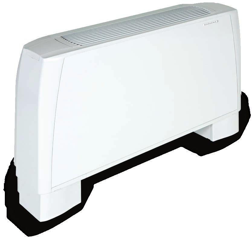
Carisma The Ultra Quiet Fan Coil
 Carisma The Ultra Quiet Fan Coil Air Conditioning Carisma / CRR Fan Coil Units Quality management systems SO 900 Cert. n 0545/4 www.euroventcertification.com www.certiflash.com CONTENTS Construction ()
CMTE. Tangential Fan Coil Series with Electronic Controlled Motor
 Tangential Fan Coil Series with Electronic Controlled Motor Designed by Very Low Electric Energy Consumption High Efficiency Extremely Low Noise Level Infra Red Remote Control Step-less Fan Speed Control
Carisma CRC. Range includes 9 air rates (from 105 to 1500 m 3 /h) It is the most comprehensive range, perfectly suited to meet
 It is the most comprehensive range, perfectly suited to meet") Carisma CRC Fan Coil Unit with Centrifugal Fan with synchronous Motor Range includes 9 air rates (from to 1500 m /h) and 5 models (for wall and ceiling installation, with casing and concealed), each equipped
Carisma CRC Fan Coil Unit with Centrifugal Fan with synchronous Motor Range includes 9 air rates (from to 1500 m /h) and 5 models (for wall and ceiling installation, with casing and concealed), each equipped
EURUS / EURUS-I. Conditioning your ambient, maximising your comfort.
 EURUS / EURUS-I Centrifugal fan coils for surface mounting or recessed installation. Cooling capacities from 0,6 to 7,6 and heating capacity from 0,8 to 9. Air folw from 0 to 0 m /h. Conditioning your
Maestro. High Pressure Fan Coil Unit with Asynchronous Motor
 Maestro High Pressure Fan Coil Unit with Asynchronous Motor The Maestro high pressure fan coils are produced in 5 sizes. Designed and built for concealed installations, they have small dimensions, are
Technical Catalogue. Cassette Fan Coils Climmy Comfort 3
 Technical Catalogue Cassette Fan Coils Climmy Comfort 3 CONTENTS INTRODUCTION Version Fan Coil Page 3 Page 4 Page 6 Page 7 Page 8 Page 12 Page 13 Page 15 Page 16 Page 18 Page 19 Page 20 Page 22 -ECM Version
CENTRIFUGAL FAN COIL UNIT VCE
 CENTRIFUGAL FAN COIL UNIT VCE 0,51 kw 11,00 kw 0,85 kw 23,75 kw 129 m 3 /h 2003 m 3 /h VCE DESIGN QUALITY COMFORTRELIABILITY 3VERSION12 SIZE DESIGN VCEx0 vertical with cabinet Air intake: bottom vertical
Fans Air Handling Units Air Distribution Products Fire Safety Air Curtains and Heating Products Water terminals SYSCOIL. Centrifugal fan coil units
 Fans Air Handling Units Air Distribution Products Fire Safety Air Curtains and Heating Products Water terminals SYSCOIL Centrifugal fan coil units SYSCOIL Fan coil units Compact, slim fan coil units. Available
Chiller Close Control Water terminals SYSCASSETTE. Water cassette units
 Chiller Close Control Water terminals SYSCASSETTE Water cassette units SYSCASSETTE Water cassette Available accessories Available in 8 different sizes and 2 versions. Due to its square design these units
MAJOR 2 NCH. Ductable units. High pressure and high capacity ductable units RANGE NCH Y NCH NCH I COADIS COMBI. Motor optional
 Y + U I COADIS COMBI High pressure and high ductable units Motor optional is a non independent air conditioning terminal unit for heating and cooling offices and hotels. With reduced dimensions and designed
Ductable Modular Fan Coil Unit VPX. Technical Brochure TM VPX-W.2GB Date : May 2004 Supersedes : TM VPX-W.1GB/08.03
 Ductable Modular Fan Coil Unit VPX Technical Brochure TM VPX-W.2GB Date : May 2004 Supersedes : TM VPX-W.1GB/08.03 Design Features Presentation The VPX fan coil unit has been specially designed to meet
Chiller, Close control and Water terminals. Air Conditioning. Light Commercial, Commercial and Industrial
 Chiller, Close control and Water terminals Air Conditioning Light Commercial, Commercial and Industrial Water Terminals 133 Water Terminals Fan coils & Cassette Centrifugal fan-coil SYSCOIL Ductable fan-coil
Fan coil units MAJOR 2 CV/CH
 CH 41 D CV 1 D MAJOR 2: Design and performance HEE impeller for increased performance Motor optional MAJOR 2 is a non-independant chilled and/or hot water supplied air conditioning Comfort unit for the
NEW. Wall controls. SkyStar SkyStar ECM Cassette Fan Coil Units. Air Conditioning. Cert. n 0545
 NEW Wall controls Cert. n 04 www.eurovent-certification.com Air Conditioning ECM Cassette Fan Coil Units CONTENTS Introduction Page 3 Main components Page 4 EUROVENT Certifications Page s Page 6 side pressure
Guide Specifications. General. Casing. Coil/Drain pan. Fan/Motor
 Guide Specifications General CR-A series ducted concealed chilled water fan coil units have an air flow range from 45 to 3060 cubic meters per hour with a capacity range from kw up to 9 kw. The CR-A series
Total cooling capacity kw Total heating capacity kw Features
 Room Fan Coils Idrofan Quality Management Systems 42N Total cooling capacity 0.75-6.35 kw Total heating capacity 0.60-9.50 kw The new generation 42N_S product range combines aesthetic and attractive design
something new in the air Technical Bulletin
 something new in the air Technical Bulletin 2 Air Leaf 2 Air Leaf 3 Innova is a company operating in the renewable energy sector and develops advanced climatic comfort systems for every season. The technological
Engineering Data Manual. New : available with EC motor. High Static Pressure Ductable Fan Coil Unit. Models 07 to to 4650 m 3 /h
 Engineering Data Manual New : available with EC motor VH High Static Pressure Ductable Fan Coil Unit Models 07 to 27 800 to 4650 m 3 /h General Characteristics Presentation On model VH 07, coils have 4
High Static Pressure Duct Fan Coil Unit
 MCAC-KTSM-2012-03 High static pressure ducted FCU High Static Pressure Duct Fan Coil Unit 1. Introduction... 2 2. Nomenclature... 2 3. Product Schedule... 3 4. External Appearance... 3 5. Features... 4
Product Data. Features/Benefits. 42BH System Fan Coil. 800 to 4000 Cfm
 Product Data 42BH System Fan Coil 800 to 4000 Cfm Satisfy All Your Design Requirements with Carrier s Versatile 42BH Fan Coil Unit A selection of 6 sizes covers capacities from 800 to 4000 cfm Choice of
Midea 50Hz AC Fan Coil Unit 2-Pipe Floor-standing Series Technical Service Manual
 Midea 50Hz AC Fan Coil Unit 2-Pipe Floor-standing Series Technical Service Manual Midea reserves the right to discontinue, or change specification or designs at any time without notices and without incurring
BRIZA 22 HYBRID HEATING & COOLING
 BRIZA 22 HYBRID HEATING & COOLING Built-in Ceiling: BABC/BT BABC/FT Built-in Wall: BABW/BT BABW/BF BABW/FT BABW/FF INFO SHEET BRIZA 22 HYBRID, COMPACT FANCOIL With EC Greentech EBM-PAPST technology Europe
42GW. Hydronic Cassette Fan Coil Units PRODUCT SELECTION DATA INSTALLATION, OPERATION AND MAINTENANCE INSTRUCTIONS EASY INSTALLATION
 PRODUCT SELECTION DATA EASY INSTALLATION INSTALLATION, OPERATION AND CENTRAL AIR DIFFUSION MAINTENANCE INSTRUCTIONS LOW ENERGY CONSUMPTION IMPROVED COMFORT ELEGANT AIR INLET GRILLE EXTREMELY QUIET OPERATION
FCX TECHNICAL BOOKLET
 FAN COIL FCX US FCX USPO This document is based on AERMEC s FCX US, USP, USPO Technical and Installa on Booklet but reflects only those sizes and configura ons currently offered by Phoenix Energy Supply.
1 AIR HANDLING UNIT TYPE AIR ACCESS 75
 SUPPLY 1 AIR HANDLING UNIT TYPE AIR ACCESS 75 Location : EXTERNAL Position : SIDE BY SIDE SLIDING PANELS for COMPLETE ACCESSIBILITY MULTI SERVICE BULKHEAD for HYDRAULIC AND ELECTRICAL CONNECTIONS Self-supporting
FCC DUCTABLE AIR TREATMENT UNIT
 FCC DUCTBLE IR TRETMENT UNIT DUCTBLE IR TRETMENT UNIT FCC 7 different sizes 3, 4 and 6 row coils 2 or 4 pipe system Horizontal installation ductable air treatment unit FCC series The ductable air treatment
FCVC Series VERTICAL FAN COILS
 VERTICAL FAN COILS The FCVC is designed for concealed, wall mounted installations with flexible heating/ cooling loads and minimal duct requirements. With a variety of options, such as fiber free insulation,
42C/D SERIES Ducted Chilled Water Fan Coil Unit With District Cooling Application
 42C/D SERIES Ducted Chilled Water Fan Coil Unit With District Cooling Application MAXIMIZING PERFORMANCE, ENERGY SAVINGS & COMFORT MODEL NUMBER NOMENCLATURE 4 2 C E T 0 0 3 4 7 0 1 2 5 42 series CISB Code
Innovative, High Performance, Quiet Units.
 Fan Coil Units Innovative, High Performance, Quiet Units. Technical Brochure TM AQF-A.4GB Date : January 2006 Supersedes : TM AQF-A.3GB/04.04 Quality, efficiency and reliability, built into every unit...
Prepared By : Checked By : Approved By : Page 1 out of 6
 Software Name Carrier AHU - Version 1.0, Patch R1.1X UNIT MODEL GENERAL SPECIFICATIONS GENERAL LOCATION / WEIGHT UNIT DIMENSION Configuration : Quick Selection Wizard Unit Orientation : Horizontal Box
VLH 504 to Air-to-Water Reverse Cycle Heat Pumps. 126 to 294 kw. 133 to 307 kw
 Air-to-Water Reverse Cycle Heat Pumps VLH 504 to 1204 126 to 294 kw 133 to 307 kw Technical Brochure TM VLH-N.3GB Date : June 2005 Supersedes : TM VLH-N.2GB/07.04 Specifications Advantages Range extension
42CET/ 42CED Series Chilled Water Fan Coil Unit Furred-in Ceiling Model 300 to 1400 cfm Electric heater option
 42CET/ 42CED Series Chilled Water Fan Coil Unit Furred-in Ceiling Model 0 to 10 cfm Electric heater option 42DC/ 42DCD Series Chilled Water Fan Coil Unit Furred-in Ceiling Model 0 to 00 cfm Electric heater
Fan coil units. HFCE, HFXE, VFCE, VFXE series Sizes 03 to to 3400 m3/h UNT-PRC007-E4
 Fan coil units HFCE, HFXE, VFCE, VFXE series Sizes 03 to 20-300 to 3400 m3/h 2012 Trane Contents Features and Benefits 4 Model Nomenclature 5 Performance Data 7 Capacities 9 Dimensional data 19 Typical
42N. Room Fan Coils PRODUCT SELECTION DATA. MAINTENANCE INSTRUCTIONS Simpified installation & large options choice
 PRODUCT SELECTION DATA Extremely quiet operation INSTALLATION, OPERATION AND Low Energy Consumption MAINTENANCE INSTRUCTIONS Simpified installation & large options choice Self regulated PTC electrical
TECHNICAL MANUAL ESTRO BLDC ESTRO BLDC FAN COILS - BRUSHLESS TECHNOLOGY. 1.5 kw kw
 GB TECHNICAL MANUAL ESTRO BLDC ESTRO BLDC FAN COILS - BRUSHLESS TECHNOLOGY 1.5 kw - 9.0 kw TABLE OF CONTENTS 1 Generalities... 3 2 Models and constructive components...4-5 3 Accessories available... 6
Address: VTS Clima L.L.C.
 Address: VTS Clima L.L.C. Business Bay, Churchill Tower, Office 2409, P.O.Box#76849 Dubai, UAE phone: +971 (4) 443 91 20 fax: +971 (4) 443 96 20 e-mail: dubai@vtsgroup.com www.uae.vtsgroup.com Index VTS
^áêëçåâ=ìåáí=åççäéêë=qvoj^ pí~åç~êç=åççäéêë=ïáíü=pí~áåäéëë=píééä=íìäáåö
 ^áêëçåâ=ìåáí=åççäéêë= pí~åç~êç=åççäéêë=ïáíü=pí~áåäéëë=píééä=íìäáåö O `çåíéåíë= page Model indication................................ 2 Eurovent...................................... 2 Capacities.....................................
Driving and Connecting Globally. Fan Coil Unit. Model : PHW-K Size : 510CMH~2720CMH. Made in Taiwan
 Driving and Connecting Globally Fan Coil Unit : PHW-K Size : 510CMH~2720CMH Made in Taiwan Features Superior low-height design. Stainless steel drain pan for condensate and corrosion protection. Flexibe-reverse
The World Leading Air-conditioning Company
 The World Leading Air-conditioning Company Table of Contents DESCRIPTIONS Model Number Nomenclature Features & Benefits Physical Dimension Fan Performance Curve (4 Row) - 40LMA024 with AC Motor - 40LMA040
Commercial Blower Coil Air Handlers
 Commercial Blower Coil Air Handlers MODEL : BDH(V)B - 048, 065, 080 7400 CMH - 14300 CMH 30 kw - 125 kw BCXB-PRC001-E4 Contents Model Number Description General Specification Standard Features Unit Configuration
Product Catalogue ARMONIA Providing indoor climate comfort
 Product Catalogue ARMONIA Providing indoor climate comfort ARMONIA 1,3-11 kw Water cassette Main applications Light commercial buildings Offi ces Shops General description Why this choice? Silent operation
UTA STANDARD. Ductable units. Range. Air handling unit with high available static pressure. NEW Eco-Design Filter. V3000 control Fresh air management
 Ductable units NEW Eco-Design Filter Air handling unit with high available static pressure V3000 control Fresh air management The range of air handling units is designed for suspended ceiling heating and
V33B High Efficiency 360 Cassette Indoor Models - 60HZ
 PRODUCT SPECIFICATIONS Low-sound, high efficiency cassette, encased in galvanized steel offers 360 airflow for immediate, equal distribution of wide-range cooling and heating. Cassette has motor-driven
CHP
 Packaged Unit Heat Pump CHP16-024-030-036-048-060 2-5 Ton Cooling 23,000-57,500 Btuh Heating 12,800-85,300 Btuh (5-25 kw) Optional Electric Heating FEATURES Designed for outdoor rooftop or ground level
Residential comfort unit OperatiOn 2 models. new builds or existing properties. 5 operating modes COnfOrmity COmpOnents
 Residential HEE motor Silent operation Heating capacity: 200 W to 4 kw Cooling capacity: 100 W to 3 kw Operation is CIAT's residential. This vertical cased unit, designed for heating and cooling, is available
Air-Cooled Liquid Chiller with integrated hydraulic module
 Air-Cooled Liquid Chiller with integrated hydraulic module Cooling only: CGAN 200-250 - 300-400 - 450-490 - 500-600 - 700-800 - 900-925 Reversible: CXAN 200-250 - 300-400 - 450-490 - 500-600 - 700-800
WE MAKE INDOOR AIR BETTER
 WE MAKE INDOOR AIR BETTER Water-Cooled Heat Pumps & Air Conditioners /4-Ton to 60-Tons Various voltages/phases Suitable for duct connections Ideal for use with free air supply plenum (2-axis adjustable
SLH 1202 to Air-to-Water Reverse Cycle Heat Pumps. With Screw Compressors. 261 to 775 kw. 287 to 853 kw
 Air-to-Water Reverse Cycle Heat Pumps SLH 1202 to 3804 With Screw Compressors 261 to 775 kw 287 to 853 kw Technical Brochure TM SLH-A.2GB Date : November 2004 Supersedes : TM SLH-A.1GB/05.04 Design Features
Midea Air Handling Unit
 Midea Air Handling Unit Floor mounted 3000CFM ---25000CFM Vertical mounted 3000CFM ---25000CFM Ceiling suspended 1000CFM ---9000CFM Midea reserves the right to improve the product and technology without
SysCoil 2. Fan Coil Units Models SVC, SVN, SHC, SHN to 8.75kW to 4.90kW. 94 to /h
 SysCoil Fan Coil Units Models SVC, SVN, SHC, SHN 0.79 to 8.75kW 0.49 to 4.90kW 94 to 930 3 /h SysCoil Quality, efficiency and reliability Vertical console units with cabinet, SVC type SVC vertical console
CLOSE CONTROL UNITS WITH CHILLED WATER COIL
 CLOSE CONTROL UNITS WITH CHILLED WATER COIL COOLING CAPACITY FROM 5 TO 154 kw 230 D 56 The range of chilled water close control units, series, is particularly indicated for use in technological centres,
fåçìëíêá~ä=~áê=åççäéêë=qvo pí~åç~êç=åççäéêë=ïáíü=ëí~áåäéëë=ëíééä=íìäáåö
 fåçìëíêá~ä=~áê=åççäéêë= pí~åç~êç=åççäéêë=ïáíü=ëí~áåäéëë=ëíééä=íìäáåö O `çåíéåíë= page Model indication..................................2 Eurovent.......................................2 Capacities......................................2
MH1WC4W-08-1-B Chilled/Hot Water 1-Way Cassette Fan Coil
 MH1WC4W-08-1-B Chilled/Hot Water 1-Way Cassette Fan Coil 4-Pipe Heat / Cool Fan Coil 24,000 BTUH Rev. 1.11 HVAC Guide Specifications Chilled and Hot Water Cassette Fan Coil 4-Pipe Nominal Size: 24,000
TECHNICAL MANUAL SOFFIO Ducted units
 TECHNICAL MANUAL SOFFIO Ducted units Page 1 INDEX 1-INTRODUCTION... 4 2-OPERATING LIMITS... 4 3- KEY TO READING CODES... 5 4-TECHNICAL SPECS... 6 5-TECHNICAL DATA (AC motors)... 7 5.1-Unit 2 pipes with
Fan coil units. Why choose Daikin fan coil units? 540 Products overview 542. Options & accessories 560. Round flow cassette 544 FWC-BT/BF 544
 Fan coil units Why choose Daikin fan coil units? 540 Products overview 542 Round flow cassette 544 FWC-BT/BF 544 4-way blow ceiling mounted cassettes 545 FWG-AT/AF 545 FWF-BT/BF 546 FWF-CT 547 Floor standing
GENERAL ELECTRIC CONCEALED CHILLED WATER FAN COIL UNITS
 GENERAL ELECTRIC CONCEALED CHILLED WATER FAN COIL UNITS ACWL Series ACWL0 thru ACWL4 00 CFM thru 400 CFM GE_ACWL_series.indd 3// : PM CONTENTS Model decoding 3 Unit features 3 Standard specifications 3-4
PVHRU Max Quiet. Engineering Solutions. Packaged Void Heat Reclaim Unit. Acoustic Testing Laboratory College of Science & Technology
 AIR HANDLERS LTD PVHRU Max Quiet Packaged Void Heat Reclaim Unit 1262 Acoustic Testing Laboratory College of Science & Technology Engineering Solutions The Company Air Handlers has been trading since May
CLIMA CANAL HYBRID HEATING AND COOLING CLIMA CANAL. Compact floor recessed fancoil unit HEATING
 Compact floor recessed fancoil unit CLIMA CANAL HEATING AND COOLING: Build-in height of 3.94 > 5.71 CLIMA CANAL HEATING ONLY: Build-in height of 3.35 > 5.43 electronic control: 0...10V signal 24V EC motor
fåçìëíêá~ä=~áê=åççäéêë=qelo pí~åç~êç=åççäéêë=ïáíü=`ì=íìäáåö
 = pí~åç~êç=åççäéêë=ïáíü=`ì=íìäáåö O `çåíéåíë= page Model indication..................................2 Eurovent.......................................2 Capacities......................................2
Versatility. Features. By installing the SILENT MV, you will never experience the disturbance of noisy ventilation again. Benefits
 Ultra quiet and low profile helicocentrifugal in-line fans suitable for a wide range of domestic and commercial applications. Fitted with sound absorbent insulation and manufactured with an adjustable
technical sales guide - 60Hz Ducted Split Units HIGH AMBIENT OPERATION 52 UPTO
 technical sales guide - 60Hz Taurus R Ducted Split Units UPTO HIGH AMBIENT OPERATION 52 O C Page CONTENTS Nomenclature.. 2 Description. 3 Features.. 3 Product Data. 4 Condensing Unit Cooling Performance
Air Cooled Water Chillers. CLS 182 to to 150 kw. Technical Brochure TM CLS-W.3GB Date : October 2004 Supersedes : TM CLS-W.2GB/07.
 Air Cooled Water Chillers CLS 182 to 602 41 to 150 kw Technical Brochure TM CLS-W.3GB Date : October 2004 Supersedes : TM CLS-W.2GB/07.04 R Specifications General characteristics The CLS air cooled water
HBC SERIES-PSC MOTOR HBCX SERIES-ECM MOTOR
 PRODUCT SPECIFICATIONS *HBC(X) *PHBC(X) *RHBC(X) *CHBC(X) Chilled Water/Hot Water 2-pipe/4-Pipe HBC SERIES- HBCX SERIES-ECM MOTOR Ceiling Concealed Horizontal -1 CFM Ceiling Concealed Ceiling Recessed
BRIZA EC 12 HYBRID. World s slimmest fan coil HEATING AND COOLING
 World s slimmest fan coil wall and ceiling installation 2-or 4-Pipe system heating and / or cooling with or without enclosure easy installation 24VDC EC motor silent, powerful, economical, sustainable
V33A Standard/High Efficiency 360 Cassette Indoor Models - 60HZ
 PRODUCT SPECIFICATIONS Low-sound, standard or high efficiency cassette, encased in galvanized steel offers 360 airflow for immediate, equal distribution of wide-range cooling and heating. Cassette has
VMDA Concealed Medium Static Ducted Indoor Models - 60HZ
 VARIABLE REFRIGERANT FLOW SYSTEMS VRF VMDA Concealed Medium Static Ducted Indoor Models - 60HZ PRODUCT ECIFICATIONS Slim, compact design for limited space requirements. Installs out of sight between the
YFCN Fan Coil Unit centrifugal fan 2 & 4 pipe system A complete range from 1.0 kw to 7.6 kw
 Fan Coil Unit centrifugal fan 2 & 4 pipe system complete range from 1.0 kw to 7.6 kw Water Systems Wired controls R Remote three speeds controller TR R + Electronic thermostat and Summer/Winter switch
Dual discharge air coolers THOR-D. Standard coolers in a revolutionary design
 Dual discharge air coolers THOR-D Standard coolers in a revolutionary design O jççéä=áåçáå~íáçå `çåíéåíë= page Model indication................................ 2 Eurovent......................................
VMDB Concealed Medium Static Ducted Indoor Models - 60HZ
 VARIABLE REFRIGERANT FLOW SYSTEMS VRF VMDB Concealed Medium Static Ducted Indoor Models - 60HZ PRODUCT ECIFICATIONS Bulletin No. 210711 March 2018 Slim, compact design for limited space requirements. Installs
SILENT MV Ultra Quiet In-line Fans
 Ultra Quiet In-line Fans 5 IP44 2 YEAR GUARANTEE Ultra quiet and low profile helicocentrifugal in-line fans suitable for a wide range of domestic and commercial applications. Fitted with sound absorbent
ERP 2015 Regulation (EU) Compliant with. No. 327/2011. Cert. n Heating. Meltemi Door Curtains
 Compliant with. No. 327/2011. Cert. n Heating. Meltemi Door Curtains") Compliant with ERP 015 Regulation (EU) No. 7/011 Cert. n 0545 Heating Door Curtains The range of SBIN door curtains offers imum flexibility in the protection of doors and open access compartments. By connecting
Compliant with ERP 015 Regulation (EU) No. 7/011 Cert. n 0545 Heating Door Curtains The range of SBIN door curtains offers imum flexibility in the protection of doors and open access compartments. By connecting
Airsock unit coolers THOR-A. Standard coolers in a revolutionary design
 Airsock unit coolers THOR-A Standard coolers in a revolutionary design O jççéä=áåçáå~íáçå `çåíéåíë= page Model indication................................ 2 Eurovent......................................
VHIA High-Static Ducted Indoor Units - 60HZ
 PRODUCT SPECIFICATIONS Compact design for limited space requirements. Installs out of sight between the drop ceiling and ceiling slab with ducted distribution to the indoor space. All models have three-stage
Concealed Ducted Split Series R22
 Concealed Ducted Split Series R22 24-60 MBH Ducted Split with Hermetic Compressor Tropical 50 Hz For more technical information please visit Table of Contents INTRODUCTION 2 NOMENCLATURE 2 UNIT RATING
Fan Coil Units. Technical Data ECDEN FWL-DT/DF
 Fan Coil Units Technical Data ECDEN10-400 FWL-DT/DF Fan Coil Units Technical Data ECDEN10-400 FWL-DT/DF TABLE OF CONTENTS FWL-DT/DF 1 Features.............................................................
AHN 064 to 304 EHN/CHN 064 to 304
 u Horizontal Packaged and Split Air Conditioners AHN 64 to 34 EHN/CHN 64 to 34 6. to 29.2 kw 6.4 to 29.4 kw Engineering Data Manual EDM AECHN-A.1GB Date : June 28 Supersedes : None Technical Description
BASTONE (dual) fancoil Units
 fancoil Units") BASTONE (dual) fancoil Units Technical information manual Western Airconditioning B.V. Tel. +31 (0) 33 247 78 00 www.western.nl 1-INTRODUCTION..3 2- WORKING CONDITION LIMITS...3 3- COANDA EFFECT 3 4- KEY
BASTONE (dual) fancoil Units Technical information manual Western Airconditioning B.V. Tel. +31 (0) 33 247 78 00 www.western.nl 1-INTRODUCTION..3 2- WORKING CONDITION LIMITS...3 3- COANDA EFFECT 3 4- KEY
Complete HVAC Capability
 Air Handling Units Brochure 1110 January 2006 Complete HVAC Capability MEA Horizontal Draw-Thru to Size 65 Vertical Draw-Thru to Size 50 1000 to 60,000 CFM Forward Curved or Airfoil Wheels Inlet Vane Option
VERTICAL SINGLE AND DOUBLE WALL BELT DRIVE AIR HANDLER DX OR CHILLED WATER COOLING WITH HOT WATER OR ELECTRIC HEAT
 VERTICAL SINGLE AND DOUBLE WALL BELT DRIVE AIR HANDLER DX OR CHILLED WATER COOLING WITH HOT WATER OR ELECTRIC HEAT SIZES FROM 600 TO 4,000 All Technical Specifications are Subject to Change without Notice.
ROOF TOP (SERIES SR) 10.8 TO 103 KW 37,000 TO 351,000 Btuh
 10.8 TO 103 KW 37,000 TO 351,000 Btuh") ROOF TOP (SERIES ) 10.8 TO 103 KW 37,000 TO 351,000 Btuh These rooftop units are complete, self contained air conditioners fully assembled, wire, charged and tested prior to shipment, each unit is delivered
ROOF TOP (SERIES ) 10.8 TO 103 KW 37,000 TO 351,000 Btuh These rooftop units are complete, self contained air conditioners fully assembled, wire, charged and tested prior to shipment, each unit is delivered
HBC SERIES-PSC MOTOR HBCX SERIES-ECM MOTOR
 PRODUCT SPECIFICATIONS *HBC(X) *PHBC(X) *RHBC(X) *CHBC(X) Chilled Water/Hot Water 2-pipe/4-Pipe HBC SERIES- HBCX SERIES-ECM MOTOR Ceiling Concealed Horizontal -1 CFM Ceiling Concealed Ceiling Recessed
HRS. Very high efficiency heat recovery units. from 300 to m³/h >90 % WITH HIGH EFFICIENCY HEAT RECOUPERATOR
 4 Lmf Clima 6 FERRARO GROUP HRS Very high efficiency heat recovery units WITH HIGH EFFICIENCY HEAT RECOUPERATOR from 3 to 4. m³/h Air-handling unit designed and manufactured for nonresidential applications,
Water terminals from 91 to 1548 m 3 /h. from 0,5 to 9,6 kw. SysCoil Comfort. Floor and ceiling fan coil units. from 0,6 to 13,6 kw
 Water terminals from 91 to 1548 m 3 /h SysCoil Comfort Floor and ceiling fan coil units from 0,5 to 9,6 kw from 0,6 to 13,6 kw SysCoil Comfort Innovation for an optimum comfort ErP 2018 TERTIAIRY H 3 /h
Silent centrifugal air heater hot water supply
 Large range : 5 to 120 Flows : 900 to 14000 m 3 /h Numerous accessories Design integrating perfectly in public buildings USE Operation in zones ES and S Extra silent and silent Forced air heating for premises
D M S 760 C01 A A 1 1
 CONTENTS Description Features Options Available Selection Method Product Data Cooling Performance Data (85 F Ambient Cooling Performance Data (95 F Ambient) Cooling Performance Data (105 F Ambient)..............................
Systempac. Fan Coil Unit / Acoustic Flex / Diffuser System Package. Systempac. January Features and Design Guide
 January 2002 Systempac Features and Design Guide Specifically Designed for Design and Build Projects. Complete package including Waterside Control Fan Coil Unit / Controls / Flexible Ducting / Plenum Box
MERIT SERIES EXPANSION VALVE AND RFC SYSTEMS
 ENGINEERING DATA Direct Drive Fan CONDENSING UNITS 13ACC MERIT SERIES EXPANSION VALVE AND RFC SYSTEMS 1.5 to 5 Ton SEER up to 14.80 Net Capacity 18,300 to 61,000 Heavy Duty Louvered Steel Fan Guard Bulletin
BUILDING EFFICIENCY Energy Efficient Variable Speed EC Motor Fan Coil Unit Solutions Model YECFC
 BUILDING EFFICIENCY Energy Efficient Variable Speed EC Motor Fan Coil Unit Solutions Model YECFC Product Introduction INTRODUCTION Johnson Controls YORK YECFC fan coil units are high efficiency, low profile,
Product Data. 42D Ducted Fan Coil Air Conditioners cfm
 Product Data 42D Ducted Fan Coil Air Conditioners 600-2000 cfm Carrier s 42D series ducted fan coil units offer design and equipment location flexibility Choice of 5 models, each available in 8 sizes For
48CWA2-00 Chilled Water Fan Coil With or Without Electric Heat 2-Pipe Heat / Cool Fan Coil 48,000 BTUH
 48CWA2-00 Chilled Water Fan Coil With or Without Electric Heat 2-Pipe Heat / Cool Fan Coil 48,000 BTUH Rev. 1.3 HVAC Guide Specifications Chilled or Hot Water with Optional Electric Heat Multi-Position
MODEL FF50 CEILING FAN
 MODEL FF50 CEILING FAN SPECIFICATION SHEET Simple installation dependability make this odor moisture removing fan a real value. Matte white polymeric blends well with any decor Torsion spring grill mounting
The Premium Quality Fan Coil Units for Horizontal Application Hydronic or Electric Heat
 Producing Quality Heating & Cooling Equipment For Over 50 Years CEA SERIES CEILING EPOSED HORIZONTAL FAN COIL UNITS The Premium Quality Fan Coil Units for Horizontal Application Hydronic or Electric Heat
TECHNICAL GUIDE R410a SPLIT SYSTEM 1.5 to 5.0 NOMINAL TONS
 Version.MDT-2016.T3.103 TECHNICAL GUIDE R410a SPLIT SYSTEM 1.5 to 5.0 NOMINAL TONS FEATURES AND BENEFITS COMPRESSOR: Compressors are protected with internal temperature and current overloads. An internal
42NL & 42NH. Hydronic Ducted Fan Coil Units PRODUCT SELECTION DATA. Modular Horizontal ducted unit. Extremely quiet operation. Low Energy Consumption
 PRODUCT SELECTION DATA Modular Horizontal ducted unit Extremely quiet operation Low Energy Consumption Flexibility for simplified installation Improved comfort Efficient Indoor Air Quality Hydronic Ducted
Chilled Water FCU. Horizontal Fan Coil 50hz CFM. A Series.
 Chilled Water FCU A Series 3-25 CFM Horizontal Fan Coil 5hz www.windind.com CONTENTS GENERAL CONSTRUCTION... 3 MODEL NUMBER NOMENCLA TURE... 4 DIMENSIONS... 5 FAN PERFORMANCE DATA... 7 GENERAL SPECIFICATIONS...
FAN POWERED TERMINAL UNITS
 Benefits: Fan powered terminals are typically used for heating and cooling of perimeter zones. Operating cost savings can be achieved through the use of waste heat recovery from the ceiling plenum and
MX-ventilation products
 MX-ventilation products Technical brochure ENG Material Weatherproof and impact resistant polypropylene UV protected Solid coloured Reliable and controlled ventilation High-quality and durable materials
TECHNICAL CATALOGUE SELF CONTAINED HORIZONTAL AIRCONDITIONERS Rev105
 TECHNICAL CATALOGUE WPHA Cooling only WPHBA Heat pump Models 091, 121, 141, 171, 201, 251, 351, 401, 501, 701, 751, 1001, 1201 Cooling capacities from 2,4 kw to 41 kw Heating capacities from 2,8 kw to
Modular Air Handling. Up to 3,500 Litres / sec. Low profile & Plant room application. Draft. Version. Second Edition A-. AirDesign 2015 AirDesign 2016
 Modular Air Handling U n i t R a n g e Up to 3,500 Litres / sec Low profile & Plant room application AirDesign 2015 AirDesign 2016 Second Edition Draft Version A-. Air Design is a proud Australian based