IN-LINE RECTANGULAR FANS IRB / IRBS IRB
|
|
|
- Rosalyn Stokes
- 5 years ago
- Views:
Transcription
1
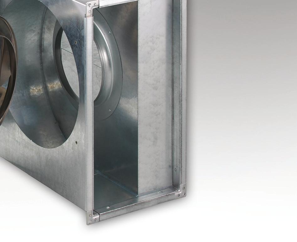
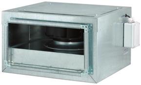
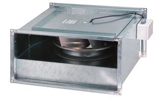
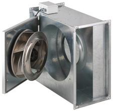
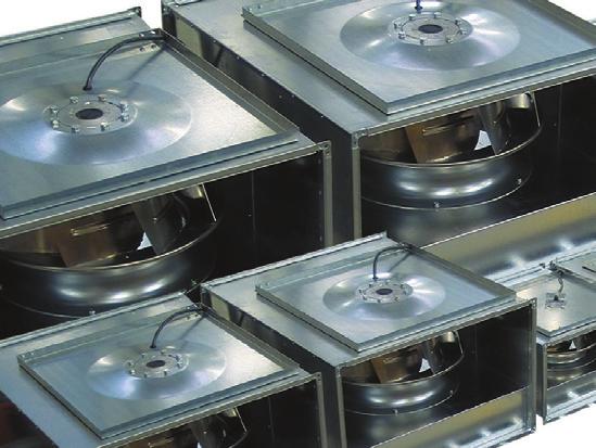
2 IN-LINE RECTANGULAR FANS IRB / IRBS IRB IN-LINE RECTANGULAR FANS IRB / IRBS IRB and IRBS are a compact series of centrifugal type exhaust and supply in-line duct fans for air conditioning systems. They are specifically designed for installation where space is limited and allow installation directly at any angle and any location along the duct system. Due to their silent operation, they can be used for direct air exhaust from the room or for air supply into the room. Characteristics of IRB/IRBS in-line rectangular fans IRBS Duct fans are designed in nine nominal connection dimensions. IRBS: sound isolated housing for all nominal dimensions. Nominal connection dimensions from 3 x 15 mm to 1 x 5 mm Single phase fans from nominal dimension 3 x 15 mm to 6 x 35 mm Three phase fans in all nominal dimensions. Air flow up to 17. m 3 /h. Static pressure up to 1.25 Pa. Direct installation into air duct systems with housing connection flanges; Housing is entirely made of galvanized sheet steel; Motor with centrifugal backward curved impeller is mounted on a swing out door, enabling easy servicing access; Impellers with backward curved blades and high hydraulic efficiency; Efficient, quality and user-friendly regulation.
3 IN-LINE RECTANGULAR FANS In-line rectangular fans IRB / IRBS Page In-line rectangular fans IRB / IRBS General Information Technical data Accessories Wiring diagrams and regulation Ordering key Installation and maintenance

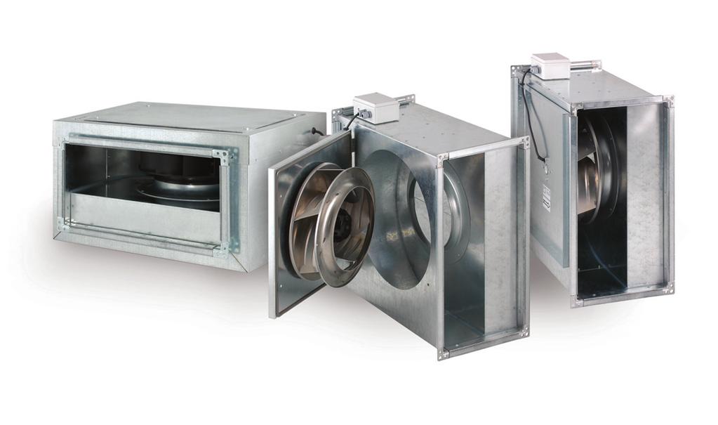
4 IN-LINE RECTANGULAR FANS GENERAL INFORMATION Application IRB / IRBS is a compact series of centrifugal type exhaust and supply in-line duct fans for air conditioning systems. They are specifically designed for installation where space is limited and allow installation directly at any angle in any point along the duct work. All fans are designed with a non overloading backward curved impeller with external rotor motor. IRBS fans with sound attenuated housing can be used where quiet operating is needed. IRB Description Main advantages of all IRB and IRBS duct fans: direct installation into air ducts with housing connecting flanges, IRB housing is made of galvanized sheet steel, IRBS sound absorbing casing is made from galvanized sheet steel and filled with highly efficient absorption material, motor with centrifugal backward curved impeller is mounted on a swing out door for free service access, stepless voltage and frequency or 5 - step controllable external rotor motor, high efficient impellers with backward curved blades, quiet operating. Typical Specifications for IRB/IRBS Fan Housing IRB / IRBS housings are constructed in nine sizes of galvanized sheet steel. IRBS housing is completely filled with highly efficient absorption material. The construction of sound isolated housing attains very high degree of attenuation. Housing connecting flanges are made of galvanized rolled steel quick-coupling elements with 2 mm edges, joined by means of angle pieces. That allows installation connections directly to or within rectangular duct work. Fan housing includes swing out door on which the motor is mounted providing free service access. IRB Electrical Motors and Impellers Electrical motors are external-rotor type mounted directly into the impeller. All single phase fans are protected by thermal limiter (WS). It is a special version of internal thermal switch, which stops the motor if it is overheated or blocked. User has to switch power supply off for restarting after eliminating cause of overheating. All three phase fans are protected by thermal overload protection brought out (TK). They must be connected to the external protective equipment: speed controllers with TK leads or motor protection switches with TK leads. Impellers are centrifugal type made of backward curved blades, which make impellers run smoothly with high static pressure output, low noise level and very high hydraulic efficiency. Impellers are made of polyamide PA 6.6, aluminium or sheet steel (galvanised or coated). Fans are dynamically balanced in two planes according to DIN ISO 194 to provide vibration free performance. 31
5 IN-LINE RECTANGULAR FANS GENERAL INFORMATION Both the motor and the impeller are cooled with optimal efficiency, being positioned directly in the centre of the air stream they generate, which increases service life. IRBS Speed Control and Electrical Connections Mono phase IRB/IRBS can be speed controlled by the Transformer with 5-step adjustable voltage output or continuously by the thyristor from 8 to 23V output. Three phase IRB/IRBS can be controlled by the Transformer with 5 step adjustable voltage output or can be controlled by the Frequency controller from to 1% of maximum fan speed. All three phase power supply regulators have leads for TK. When there is no speed control required, IRB/IRBS three phase fans must be connected on motor protection switches with TK: ZSK 25 T (/H). Fans are supplied with an external electrical wiring box and are pre-wired with motor connections leads. Measurements of Characteristics Acoustic performances of all IRB and IRBS fans are measured in reverberation room according to ISO Air flow and static pressure characteristics for all IRB and IRBS fans are measured according to ISO
6 IN-LINE RECTANGULAR FANS TECHNICAL DATA D B3 B2 B1 H1 H2 H3 C3 IRB Characteristic (page 314 and 315) Dimensions in mm Nominal Construction Size Type B H B1 B2 B3 H1 H2 H3 C3 D Air fl ow Maximum Pressure Performances Speed Noise level (at 1m) Power Voltage Q max p max n L pa P U (m 3 /h) (Pa) (min -1 ) (db(a)) (W) (V) 1 IRB 315 2SM IRB 315 2ST IRB 42 2SM IRB 42 2ST IRB 42 2HM IRB 42 2HT IRB 525 4SM IRB 525 4ST IRB 525 2HM IRB 525 2HT / / / / / IRB 53 6SM IRB 53 4HM IRB 53 4HT IRB 63 4SM IRB 63 4ST IRB 635 4SM IRB 635 4ST IRB 635 4HM IRB 635 4HT IRB 74 4ST IRB 85 4ST IRB 85 4HT IRB 15 4ST IRB 15 4HT * 2-2 poles 4-4 poles 6-6 poles ** S - standard power at nominal dimension H - higher power at nominal dimension *** M - mono phase motor T - 3-phase motor 312
7 D IN-LINE RECTANGULAR FANS TECHNICAL DATA B4 B3 B2 B1 H1 H2 H3 H4 C3 IRBS Characteristic (page 314 and 315) Dimensions in mm Nominal Construction Size Type B H B1 B2 B3 B4 H1 H2 H3 H4 C3 D Air flow Maximum Pressure Performances Speed Noise level (at 1m) Power Voltage Q max p max n L pa P U (m 3 /h) (Pa) (min -1 ) (db(a)) (W) (V) 1 IRBS 315 2SM IRBS 315 2ST IRBS 42 2SM IRBS 42 2ST IRBS 42 2HM IRBS 42 2HT IRBS 525 4SM IRBS 525 4ST IRBS 525 2HM IRBS 525 2HT / / / / / IRBS 53 6SM IRBS 53 4HM IRBS 53 4HT IRBS 63 4SM IRBS 63 4ST IRBS 635 4SM IRBS 635 4ST IRBS 635 4HM IRBS 635 4HT IRBS 74 4ST IRBS 85 4ST IRBS 85 4HT IRBS 15 4ST IRBS 15 4HT * 2-2 poles 4-4 poles 6-6 poles ** S - standard power at nominal dimension H - higher power at nominal dimension *** M - mono phase motor T - 3-phase motor 313
8 IN-LINE RECTANGULAR FANS TECHNICAL DATA Selection diagram for Mono phase fans For corresponding fan type see pages 312 and
9 IN-LINE RECTANGULAR FANS TECHNICAL DATA Selection diagrams for 3-phase fans Y Legend: 1- : delta wiring ;1-Y: star wiring For corresponding fan type see pages 312 and
10 IN-LINE RECTANGULAR FANS TECHNICAL DATA Size 1 Nominal Rectangular Duct Dimensions 3x15 Type: IRB 315 2SM / IRBS 315 2SM IRB 315 2ST / IRBS 315 2ST Duct width (mm) 3 Duct height (mm) 15 Max. Air flow: Qmax (m 3 /h) Temperature of transported Air and of Ambient ( C) Power (W) Voltage / Frequency (V / Hz) 23 / 5 / 5 Current (A),25,9 Speed / rpm (min -1 ) Motor: Insulation class B B Motor: Type of protection IP 44 IP 44 Motor: Wiring diagram No.1 page: 33 No.2 page: 33 Weight (kg) 8 / 14 8 / 14 Sound pressure level at 1m according to ISO 3741 IRB: (db(a)) IRBS: (db(a)) IRB 315 2SM / T Installation dimensions in (mm) IRBS 315 2SM / T Installation dimensions in (mm) IRB / IRBS 315 2SM and IRB / IRBS 315 2ST Characteristics: IRB/IRBS 315 2SM IRB/IRBS 315 2ST Regulation - pg: IRB / IRBS 315 2SM IRB / IRBS 315 2ST Stepless controller BR 1 M page:331 / 5-step controller SR 1,5 M page:332 SRK 1,5 T page:333 ON/OFF switch RS 3 P page:336 RS 6 P page:336 Motor protection switch / ZSK 25 T(/H) page:336 Frequency controller / FR,37 M page:
11 IN-LINE RECTANGULAR FANS TECHNICAL DATA Size 2 Nominal Rectangular Duct Dimensions x2 Type: IRB 42 2SM / IRBS 42 2SM IRB 42 2ST / IRBS 42 2ST IRB 42 2HM / IRBS 42 2HM IRB 42 2HT / IRBS 42 2HT Duct width (mm) Duct height (mm) 2 Max. Air flow: Qmax (m 3 /h) Temperature of transported Air and of Ambient ( C) Power (W) Voltage / Frequency (V / Hz) 23 / 5 / 5 23 / 5 / 5 Current (A),38,12,7,34 Speed / rpm (min -1 ) Motor: Insulation class B B F F Motor: Type of protection IP 44 IP 44 IP 44 IP 44 Motor: Wiring diagram / page No.1 page: 33 No.2 page: 33 No.1 page: 33 No.2 page: 33 Weight (kg) 13 / / / / 23 Sound pressure level at 1m according to ISO 3741 IRB: (db(a)) IRBS: (db(a)) IRB 42 2SM / T, IRB 42 2HM / T Installation dimensions in (mm) IRBS 42 2SM / T, IRBS 42 2HM / T Installation dimensions in (mm) 287 (331) (28) * The value in bracket ( ) is given for versions IRB 42 2HM and IRB 42 2HT. IRB / IRBS 42 2SM, IRB / IRBS 42 2ST Characteristics: **The value in bracket ( ) is given for versions IRBS 42 2HM and IRBS 42 2HT. IRB / IRBS 42 2HM, IRB / IRBS 42 2HT Characteristics: IRB/IRBS 42 2SM IRB/IRBS 42 2ST IRB/IRBS 42 2HM IRB/IRBS 42 2HT Regulation - pg: IRB / IRBS 42 2SM IRB / IRBS 42 2ST IRB / IRBS 42 2HM IRB / IRBS 42 2HT Stepless controller BR 1 M page:331 / BR 1 M page:331 / 5-step controller SR 1,5 M page:332 SRK 1,5 T page:333 SR 1,5 M page:332 SRK 1,5 T page:333 ON/OFF switch RS 3 P page:336 RS 6 P page:336 RS 3 P page:336 RS 6 P page:336 Motor protection switch / ZSK 25 T(/H) page:336 / ZSK 25 T(/H) page:336 Frequency controller / FR,37 M page:334 / FR,37 M page:
12 IN-LINE RECTANGULAR FANS TECHNICAL DATA Size 3 Nominal Rectangular Duct Dimensions 5x25 Type: IRB 525 4SM / IRBS 525 4SM IRB 525 4ST / IRBS 525 4ST IRB 525 2HM / IRBS 525 2HM IRB 525 2HT / IRBS 525 2HT Duct width (mm) 5 Duct height (mm) 25 Max. Air flow: Qmax (m 3 /h) /128 Temperature of transported Air and of Ambient ( C) Power (W) /185 Voltage / Frequency (V / Hz) 23 / 5 / 5 23 / 5 / 5 Current (A),44,3,97,5 Speed / rpm (min -1 ) /226 Motor Insulation class B B F F Motor Type of protection IP 44 IP 44 IP 44 IP 44 Motor wiring diagram / page No.1 page: 33 No.3 page: 33 No.1 page: 33 No.4 page: 33 Weight (kg) 18 / / / / 28 Sound pressure level at 1m according to ISO 3741 IRB: (db(a)) /49 IRBS: (db(a)) /45 IRB 525 4SM / T, IRB 525 2HM / T Installation dimensions in (mm) IRBS 525 4SM / T, IRBS 525 2HM / T Installation dimensions in (mm) 49 (372) (321) * The value in bracket ( ) is given for versions IRB 525 2HM and IRB 525 2HT. IRB / IRBS 525 4SM, IRB / IRBS 525 4ST Characteristics: **The value in bracket ( ) is given for versions IRBS 525 2HM and IRBS 525 2HT. IRB / IRBS 525 2HM, IRB / IRBS 525 2HT Characteristics: IRB/IRBS 525 4SM IRB/IRBS 525 4ST IRB/IRBS 525 2HM IRB/IRBS 525 2HT: connection IRB/IRBS 525 2HT: Y connection Regulation - pg: IRB / IRBS 525 4SM IRB / IRBS 525 4ST IRB / IRBS 525 2HM IRB / IRBS 525 2HT Stepless controller BR 1 M page:331 / BR 1,5 M page:331 / 5-step controller SR 1,5 M page:332 SRK 1,5 T page:333 SR 1,5 M page:332 SRK 1,5 T page:333 ON/OFF switch RS 3 P page:336 RS 6 P page:336 RS 3 P page:336 RS 9 P page:336 Motor protection switch / ZSK 25 T(/H) page:336 / ZSK 25 T(/H) page:336 Frequency controller / FR,37 M page:334 / FR,37 M page:
13 IN-LINE RECTANGULAR FANS TECHNICAL DATA Size 4 Nominal Rectangular Duct Dimensions 5x3 Type: IRB 53 6SM / IRBS 53 6SM IRB 53 4HM / IRBS 53 4HM IRB 53 4HT / IRBS 53 4HT Duct width (mm) 5 Duct height (mm) 3 Max. Air flow: Qmax (m 3 /h) Temperature of transported Air and of Ambient ( C) Power (W) Voltage / Frequency (V / Hz) 23 / 5 23 / 5 / 5 Current (A),3,75,53 Speed / rpm (min -1 ) Motor: Insulation class F F F Motor: Type of protection IP 44 IP 44 IP 44 Motor: Wiring diagram No.1 page: 33 No.1 page: 33 No.2 page: 33 Weight (kg) 29 / 42 3 / 42 3 / 42 Sound pressure level at 1m according to ISO 3741 IRB: (db(a)) IRBS: (db(a)) IRB 53 6SM, IRB 53 4HM / T Installation dimensions in (mm) IRBS 53 6SM, IRBS 53 4HM / T Installation dimensions in (mm) IRB / IRBS 53 6SM Characteristics: IRB / IRBS 53 4HM, IRB / IRBS 53 4HT Characteristics: IRB/IRBS 53 6SM IRB/IRBS 53 4HM IRB/IRBS 53 4HT Regulation - pg: IRB / IRBS 53 6SM IRB / IRBS 53 4HM IRB / IRBS 53 4HT Stepless controller BR 1 M page:331 BR 1 M page:331 / 5-step controller SR 1,5 M page:332 SR 1,5 M page:332 SRK 1,5 T page:333 ON/OFF switch RS 3 P page:336 RS 3 P page:336 RS 6 P page:336 Motor protection switch / / ZSK 25 T(/H) page:336 Frequency controller / / FR,37 M page:
14 IN-LINE RECTANGULAR FANS TECHNICAL DATA Size 5 Nominal Rectangular Duct Dimensions 6x3 Type IRB 63 4SM / IRBS 63 4SM IRB 63 4ST / IRBS 63 4ST Duct width (mm) 6 Duct height (mm) 3 Max. Air flow: Qmax (m 3 /h) Temperature of transported Air and of Ambient ( C) Power (W) Voltage / Frequency (V / Hz) 23 / 5 / 5 Current (A) 1,1.55 Speed / rpm (min -1 ) Motor: Insulation class F F Motor: Type of protection IP 44 IP 44 Motor: Wiring diagram / page No.1 page: 33 No.3 page: 33 Weight (kg) 35 / / 49 Sound pressure level at 1m according to ISO 3741 IRB: (db(a)) IRBS: (db(a)) IRB 63 4SM / T Installation dimensions in (mm) IRBS 63 4SM / T Installation dimensions in (mm) IRB / IRBS 63 4SM, IRB / IRBS 63 4ST Characteristics: IRB/IRBS 63 4SM IRB/IRBS 63 4ST Regulation - pg: IRB / IRBS 63 4SM IRB / IRBS 63 4ST Stepless controller BR 1,5 M page:331 / 5-step controller SR 1,5 M page:332 SRK 1,5 T page:333 ON/OFF switch RS 3 P page:336 RS 6 P page:336 Motor protection switch / ZSK 25 T(/H) page:336 Frequency controller / FR,37 M page:334 32
15 Size 6 Nominal Rectangular Duct Dimensions 6x35 Type IRB 635 4SM / IRBS 635 4SM IRB 635 4ST / IRBS 635 4ST IRB 635 4HM / IRBS 635 4HM IN-LINE RECTANGULAR FANS TECHNICAL DATA IRB 635 4HT / IRBS 635 4HT Duct width (mm) 6 Duct height (mm) 35 Max. Air flow: Qmax (m 3 /h) Temperature of transported Air and of Ambient ( C) Power (W) Voltage / Frequency (V / Hz) 23 / 5 / 5 23 / 5 / 5 Current (A) 1,1,55 2,35 1,27 Speed / rpm (min -1 ) Motor: Insulation class F F F F Motor: Type of protection IP 54 IP 54 IP 54 IP 54 Motor: Wiring diagram / page No.1 page: 33 No.3 page: 33 No.1 page: 33 No.3 page: 33 Weight (kg) 39 / / / / 59 Sound pressure level at 1m according to ISO 3741 IRB: (db(a)) IRBS: (db(a)) IRB 635 4SM / T, IRB 635 4HM / T Installation dimensions in (mm) IRBS 635 4SM / T, IRBS 635 4HM / T Installation dimensions in (mm) IRB / IRBS 635 4SM, IRB / IRBS 4ST Characteristics: IRB / IRBS 635 4HM, IRB / IRBS 635 4HT Characteristics: IRB/IRBS 635 4SM IRB/IRBS 635 4ST IRB/IRBS 635 4HM IRB/IRBS 635 4HT Regulation - pg: IRB / IRBS 635 4SM IRB / IRBS 635 4ST IRB / IRBS 635 4HM IRB / IRBS 635 4HT Stepless controller BR 1,5 M page:331 / BR 2,5 M page:331 / 5-step controller SR 1,5 M page:332 SRK 1,5 T page:333 SR 3,5 M page:332 SRK 1,5 T page:333 ON/OFF switch RS 3 P page:336 RS 6 P page:336 RS 3 P page:336 RS 6 P page:336 Motor protection switch / ZSK 25 T(/H) page:336 / ZSK 25 T(/H) page:336 Frequency controller / FR,37 M page:334 / FR,75 M page:
16 IN-LINE RECTANGULAR FANS TECHNICAL DATA Size 7 Nominal Rectangular Duct Dimensions 7x Type IRB 74 4ST / IRBS 74 4ST Duct width (mm) 7 Duct height (mm) Max. Air flow: Qmax (m 3 /h) 56 Temperature of transported Air and of Ambient ( C) -4 7 Power (W) 7 Voltage / Frequency (V / Hz) / 5 Current (A) 1,34 Speed / rpm (min -1 ) 13 Motor: Insulation class F Motor: Type of protection IP 54 Motor: Wiring diagram No.3 page: 33 Weight (kg) 63 / 93 Sound pressure level at 1m according to ISO 3741 IRB: (db(a)) 59 IRBS: (db(a)) 52 IRB 74 4ST Installation dimensions in (mm) IRBS 74 4ST Installation dimensions in (mm) IRB / IRBS 74 4ST Characteristics: IRB/IRBS 74 4ST Regulation - pg: IRB / IRBS 74 4ST Stepless controller / 5-step controller SRK 1,5 T page:333 ON/OFF switch RS 6 P page:336 Motor protection switch ZSK 25 T(/H) page:336 Frequency controller FR,75 M page:
17 IN-LINE RECTANGULAR FANS TECHNICAL DATA Size 8 Nominal Rectangular Duct Dimensions 8x5 Type: IRB 85 4ST / IRBS 85 4ST IRB 85 4HT / IRBS 85 4HT Duct width (mm) 8 Duct height (mm) 5 Max. Air flow: Qmax (m 3 /h) 7 16 Temperature of transported Air and of Ambient ( C) Power (W) Voltage / Frequency (V / Hz) / 5 / 5 Current (A) 2,69 4,96 Speed / rpm (min -1 ) Motor: Insulation class F F Motor: Type of protection IP 54 IP 54 Motor: Wiring diagram / page No.3 page: 33 No.3 page: 33 Weight (kg) 9 / / 135 Sound pressure level at 1m according to ISO 3741 IRB: (db(a)) IRBS: (db(a)) IRB 85 4ST, IRB 85 4HT Installation dimensions in (mm) IRBS 85 4ST, IRBS 85 4HT Installation dimensions in (mm) 636 (676) (625) * The value in bracket ( ) is given for versions IRB 85 4HT. IRB / IRBS 85 4ST Characteristics: **The value in bracket ( ) is given for versions IRBS 85 4HT. IRB / IRBS 85 4HT Characteristics: IRB/IRBS 85 4ST IRB/IRBS 85 4HT Regulation - pg: IRB / IRBS 85 4ST IRB / IRBS 85 4HT Stepless controller / / 5-step controller SRK 4 T page:333 SRK 6 T page:333 ON/OFF switch RS 6 P page:336 RS 6 P page:336 Motor protection switch ZSK 25 T(/H) page:336 ZSK 25 T(/H) page:336 Frequency controller FR 1,5 M page:334 FR 2,4 T page:
18 IN-LINE RECTANGULAR FANS TECHNICAL DATA Size 9 Nominal Rectangular Duct Dimensions 1x5 Type: IRB 15 4ST / IRBS 15 4ST IRB 15 4HT / IRBS 15 4HT Duct width (mm) 1 Duct height (mm) 5 Max. Air flow: Qmax (m 3 /h) Temperature of transported Air and of Ambient ( C) Power (W) Voltage / Frequency (V / Hz) / 5 / 5 Current (A) 4,98 7,19 Speed / rpm (min -1 ) Motor: Insulation class F F Motor: Type of protection IP 54 IP 54 Motor: Wiring diagram No.3 page: 33 No.3 page: 33 Weight (kg) 114 / / 17 Sound pressure level at 1m according to ISO 3741 IRB: (db(a)) IRBS: (db(a)) IRB 15 4ST, IRB 15 4HT Installation dimensions in (mm) IRBS 15 4ST, IRBS 15 4HT Installation dimensions in (mm) (625) IRB / IRBS 15 4ST Characteristics: IRB / IRBS 15 4HT Characteristics: IRB/IRBS 15 4ST IRB/IRBS 15 4HT Regulation - pg: IRB / IRBS 15 4ST IRB / IRBS 15 4HT Stepless controller / / 5-step controller SRK 6 T page:333 SRK 8 T page:333 ON/OFF switch RS 6 P page:336 RS 6 P page:336 Motor protection switch ZSK 25 T(/H) page:336 ZSK 25 T(/H) page:336 Frequency controller FR 2,4 T page:335 FR 4 T page:
19 IN-LINE RECTANGULAR FANS ACCESSORIES Sound attenuators installation dimensions in (mm) Sound Attenuator DZ B1+2 B2 B3 H1+2 H2 H3 Sound attenuators are designed to attenuate fan noises. Based on numerous practical calculations it has been established that the said systems require maximum sound attenuation in the 25 Hz octave band. In other frequency bands, attenuation performances of the attenuators are also well adapted to ventilation systems acoustic requirements. The attenuators are equipped with splitter guide rails at inlet and outlet for low pressure losses. Sound attenuators dimensions in (mm) B1 B2 B3 H1 H2 H3 Length DZ DZ DZ DZ DZ DZ DZ DZ DZ Sound attenuation capacity D (db) Frequency (Hz) Sound absorbing rate (db(a)) IRB / IRBS version S IRB / IRBS version H IRB / IRBS version S Pressure drop ( p) DZ / 23 / DZ DZ DZ DZ / 57 / DZ DZ / 3 / DZ DZ Pressure drop in attenuator is given for 2/3 of maximum air flow volume. IRB / IRBS version H 325


20 IN-LINE RECTANGULAR FANS ACCESSORIES Steel overpressure dampers JNŽ-4, JNŽ-4/3, JNŽ-6, JNŽ-6/3 They can be applied where the automatic break of the supply and exhaust air is required after IRB or IRBS fan has been turned off. Steel overpressure dampers JNŽ-4 and JNŽ-6 consist of supporting frame made of galvanized sheet steel, and horizontal swinging vanes of sheet aluminium. The horizontal vanes are inserted into plastic bearings, temperature resistant up to 8 C. Sealing stripe, attached on lower part of vanes reduces noise. Ordering key: page 337 JNŽ-4 JNŽ H1+2/B1+2 H1+2/B1+2 H2/B2 H3/B3 H1+2/B1+2 H1+2/B1+2 H2/B2 H3/B3 JNŽ-4 JNŽ-6 JNŽ-4/3 Overpressure damper is fastened in built-in frame of angle steel. Designation: JNŽ-4/3 JNŽ-6/3 Overpressure damper is fastened in built-in frame of angle steel. Designation: JNŽ-6/3 Steel overpressure dampers dimensions in (mm) B1 B2 B3 H1 H2 H3 Pressure drop ( p) IRB / IRBS version S JNŽ-4 315, JNŽ-4/3 315, JNŽ-6 315, JNŽ-6/ / JNŽ-4 42, JNŽ-4/3 42, JNŽ-6 42, JNŽ-6/ JNŽ-4 525, JNŽ-4/3 525, JNŽ-6 525, JNŽ-6/ JNŽ-4 53, JNŽ-4/3 53, JNŽ-6 53, JNŽ-6/ JNŽ-4 63, JNŽ-4/3 63, JNŽ-6 63, JNŽ-6/ / JNŽ-4 635, JNŽ-4/3 635, JNŽ-6 635, JNŽ-6/ JNŽ-4 74, JNŽ-4/3 74, JNŽ-6 74, JNŽ-6/ / JNŽ-4 85, JNŽ-4/3 85, JNŽ-6 85, JNŽ-6/ JNŽ-4 15, JNŽ-4/3 15, JNŽ-6 15, JNŽ-6/ Pressure drop is given for 2/3 of maximum air flow volume. IRB / IRBS version H 326

21 IN-LINE RECTANGULAR FANS ACCESSORIES Volume control dampers RŽ-1 Volume control dampers are designed are designed for regulation of air flow and pressure in ventilating ducts and air conditioning devices. They are installed as independent device or combined with protection- or overpressure louvers. They are made of galvanised sheet steel. Volume control dampers consist of supporting frame and interconnected blades which are inserted into PVC bearings. Blades can be moved manually or by electric actuator. Ordering key: page 337 Manual control with handle mechanism for locking selected position Type RŽ-1/R Motor control with electric actuator control via electric actuator (15 Nm) 75 Power driven by electric actuator CODE BELIMO, JOVENTA, Regulation Torque Electrical power Voltage Hidria MOTOR (/) (Nm) (W) (V) Catalogue B7 SM 24 J7 DA 1 ON/OFF 15 1,8 DC 24 B8 SM 23 J8 DA 2 ON/OFF 15 1,6 AC 23 B9 SM 24 SR J9 DM 1.1 CONTINUOUS 15 3, DC 24 B1 SM 22 SR J1 DM 2.2 CONTINUOUS 15 3,6 AC 23 Wiring diagrams End position control a - opened OPEN b - opened CLOSED
22 IN-LINE RECTANGULAR FANS ACCESSORIES Installation types: 18 H1+2/B1+2 H2/B2 H3/B3 18 H1+2/B1+2 H2/B2 H3/B3 Steel overpressure dampers dimensions in (mm) B1 B2 B3 H1 H2 H3 RŽ-1B RŽ-1B RŽ-1B RŽ-1B RŽ-1B RŽ-1B RŽ-1B RŽ-1B RŽ-1B RŽ-1B, RŽ-1B/G RŽ-1B/3, RŽ-1B/G/3 Overpressure damper is fastened in built-in frame of angle steel. Designation: RŽ-1B/3, RŽ-1B/G/3 Pressure drop: air flow direction p α H/B Pressure drop p(pa) RŽ-1B blade angle W A L (d B (A )) Air velocity v (m/s) a ( ) - Blade inclination p (Pa) - Pressure drop L WA (db (A)) - Sound power level 328
23 IN-LINE RECTANGULAR FANS ACCESSORIES Protection Grill ZM Dimensions in (mm) B1 B3 H1 H3 ZM ZM H1 H3+2 ZM ZM ZM B1 B3+2 ZM ZM ZM ZM Flexible Connector FS B1+2 B2 B3 H1+2 H2 H3 Dimenzije (mm) B1 B2 B3 H1 H2 H3 FS FS FS FS FS FS FS FS FS
24 IN-LINE RECTANGULAR FANS WIRING DIAGRAMS AND REGULATION Wiring diagrams for mono phase IRB/IRBS fans without speed controllers Wiring diagram 1 IRB/IRBS 315 2SM, IRB/IRBS 42 2SM, IRB/IRBS 42 2HM, IRB/IRBS 525 4SM, IRB/IRBS 525 2HM, IRB/IRBS 53 6SM, IRB/IRBS 53 4HM, IRB/IRBS 63 4SM, IRB/IRBS 635 4SM and IRB/IRBS 635 4HM: N L 1 blue 2 black C 3 white 4 brown green/yellow IRB/IRBS Wiring diagrams for three phase IRB/IRBS fans without speed controllers Wiring diagram 2 IRB/IRBS 315 2ST, IRB/IRBS 42 2ST, IRB/IRBS 42 2HT, IRB/IRBS 53 4HT: L1 L2 1 2 L3 3 TK 4 TK 5 1 black 2 blue 3 brown 4 grey: thermal overload protection contacts of the fan 5 grey: thermal overload protection contacts of the fan green/yellow IRB/IRBS Wiring diagram 3 IRB/IRBS 525 4ST, IRB/IRBS 63 4ST, IRB/IRBS 635 4ST, IRB/IRBS 635 4HT, IRB/IRBS 74 4ST, IRB/IRBS 85 4ST, IRB/IRBS 85 4HT, IRB/IRBS 15 4ST and IRB/IRBS 15 4HT: L1 L2 L3 TK IRB/IRBS Y connection only! TK 8 1 black 2 yellow 3 blue 4 green 5 brown 6 white 7 grey: thermal overload protection contacts of the fan 8 grey: thermal overload protection contacts of the fan green/yellow Wiring diagram 4 IRB/IRBS 525 2HT: L1 L2 L Y connection IRB/IRBS TK TK L1 L2 L3 TK TK IRB/IRBS connection 1 = U1 black 2 = W2 yellow 3 = V1 blue 4 = U2 green 5 = W1 brown 6 = V2 white 7 grey: thermal overload protection contacts of the fan 8 grey: thermal overload protection contacts of the fan green/yellow 33

25 IN-LINE RECTANGULAR FANS WIRING DIAGRAMS AND REGULATION Stepless speed controllers: BR 1 M, BR 1,5 M, BR 2,5 M Manual voltage controllers for mono phase fans (23V, 5Hz) for speed and air flow control. The controllers regulate output voltage from 8 to 23V. Suitable for inset as well as for surface mounting. The splash-proved housing allows use in demanding (moist) environments like kitchens, bathrooms etc. Inset mounting gives splash proof IP 44, surface mounting with the mounting case gives splash proof IP 54. Several fans can be controlled by BR 1 M, BR 1,5 M or BR 2,5 M parallel as long as the current limit is not exceeded. They can be used only with motors with built-in overheating protection. 2` BR 1 M BR 1,5 M BR 2,5 M Current rating (A) 1, 1,5 2,5 Current fuse (A) F 1,25 A H F 2, A H F 3,15 A H Supply (V / Hz) 23 / 5 23 / 5 23 / 5 Extra output (V / Hz) 23 / 5 23 / 5 23 / 5 Weight (kg),25,29,3 L N 1` N N M 23V infinitely variable speed control from minimum to maximum built-in temperature cut-off fuse spare fuse included minimum speed by trimmer inset mounting: IP44, surface mounting: IP54 plastic enclosure, ABS, RAL 91 maximum ambient temperature: 35 C 1 - non regulated output 23V 2 - fuse box with spare fuse Stepless mono phase controller with TK: BRK 3 M BRK 3 M is electronic speed controller, which control the speed of mono phase fans by varying the supplied voltage. Controller starts the motor at the highest speed for about 6-7 seconds, after this, the motor speed will descend to the required speed, following the position of the potentiometer. Its IP 54 case allows the use in demanding environments. BRK 3 M controller fitted out with TK provides an excellent protection for motors with thermal cut-out contacts. They switch off power supply to the motor when thermal contact in the motor windings is tripped. BRK 3 M has NO automatic restart! After elimination of the cause of the overheating, the fan can be restarted by putting the switch in OFFposition for a few moments. This alarm situation is indicated by the red telltale and can be branched off through the terminals N-A. BRK 3 M also offers non regulated 23 V / 5 Hz output. BRK 3 M Current rating (A) 3, Current fuse (A) F 5, A H Supply (V / Hz) 23 / 5 Extra output: (V / Hz) 23 / 5 variable speed control from maximum to minimum minimum setting by trimmer motor protection by connection thermal overheating contacts of the motor ON/OFF switch plastic enclosure, ABS, RAL 92 IP 54 minimum speed by trimmer not regulated 23 V / 5 Hz output maximum ambient temperature: 35 C 331
. They are applicable with fans for 5-step air flow control. The fan speed can be chosen manually with control knob on the front panel.")


26 IN-LINE RECTANGULAR FANS WIRING DIAGRAMS AND REGULATION 5 - step mono phase controller: SR 1,5 M and SR 3,5 M SR 1,5 M and SR 3,5 M are a mono phase transformers with voltage output in five fixed steps ( V). They are applicable with fans for 5-step air flow control. The fan speed can be chosen manually with control knob on the front panel. They can regulate two or more fans parallel as long as the current limit is not exceeded. They can be used only with motors with built-in overheating protection. SR 1,5 M and SR 3,5 M regulators also have not regulated 23 V / 5 Hz output. SR 1,5 SR 3,5 M Maximum Current (A) 1,5 3,5 Current fuse (A) 2, 5 Supply (V / Hz) 23 / 5 23 / 5 Extra output (V / Hz) 23 / 5 23 / 5 Weight (kg) 3,4 4,7 L N F L N Pe L1 N Pe N U 23 Vac output M 23V plastic enclosure IP54 5 positions switch with OFF position indicator lamp current fuse ready mounted cable glands maximum ambient temperature: 35 C F - Fuse N - L1: - 23 V unregulated output 5 - step mono phase controller with TK: SRK 3,5 M SRK 3,5 M is a mono phase transformer with voltage output in five fixed steps ( V). It is applicable with fans for 5-step air flow control. The fan speed can be chosen manually with control knob on the front panel. It can regulate two or more fans parallel as long as the current limit is not exceeded. It is fitted out with TK contacts for motor overload protection. Single phase motors which have thermal overload protector (TOP) brought out must be connected to the their thermo contacts. They switch off power supply to the motor when thermal contact in the motor windings is tripped. It has NO automatic restart! The fan can be manually restarted by turning the switch into the position for a few seconds after the fault is eliminated and the temperature of motor winding is dropt down. SRK 3,5 M speed controller is equipped with not regulated 23 V / 5 Hz output. L N F L N Pe N U Pe N L1 TK TK M 23V izhod: 23 V / 5Hz F - Fuse N - L1: - 23 V unregulated output TK - motor overload protection contacts for the fan s motor SRK 3,5 M Maximum Current (A) 3,5 Current fuse (A) 5, Supply (V / Hz) 23 / 5 Extra output (V / Hz) 23 / 5 Weight (kg) 5, plastic enclosure IP54 5 positions switch with OFF position motor protection by connecting thermal overheating contacts of the motor indicator lamp current fuse ready mounted cable glands maximum ambient temperature: 35 C 332
. They are applicable with fans for 5-step speed and air flow control. The fan speed can be chosen manually with control knob on the front panel.")
 contacts for thermal motor protection switches off power supply to the motor when thermal contact in the motor windings is tripped. They have NO automatic restart!")
27 IN-LINE RECTANGULAR FANS WIRING DIAGRAMS AND REGULATION 5 - step three phase controllers with TK: SRK 1,5 T, SRK 4 T, SRK 6 T, SRK 8 T They are a three phase transformers with voltage output in five fixed steps ( V). They are applicable with fans for 5-step speed and air flow control. The fan speed can be chosen manually with control knob on the front panel. They can regulate two or more fans parallel as long as the current limit is not exceeded. Their (TK) contacts for thermal motor protection switches off power supply to the motor when thermal contact in the motor windings is tripped. They have NO automatic restart! The fan can be manually restarted by turning the switch into the position for a few seconds after the fault is eliminated and the temperature of motor winding is dropt down. Not regulated 23 V / 5 Hz outputs offer possibility to connect any other mono phase accessories. SRK 1,5 T SRK 4 T SRK 6 T SRK 8 T Maximum (A) 1,5 4, 6, 8, Current Supply (V / Hz) / 5 / 5 / 5 / 5 Extra output (V / Hz) 23 / 5 23 / 5 23 / 5 23 / 5 Weight (kg) 12,2 18,5 24,6 28, sheet steel IP54 5 positions switch with OFF position indicator lamp motor protection by connection thermal overheating contacts of the motor ready mounted cable glands maximum ambient temperature: 35 C Pe R S T N Pe U V W Pe N L1 TK TK Pe R S T N Pe U V W Pe N L1 TK TK L1 L2 L3 N M 3~ V 23 Vac output L1 L2 L3 N M 3~ V 23 Vac output For fans with TK Pe N L1: - 23 V unregulated output TK motor overload protection contacts for the fan s motor For fans without TK Pe N L1: - 23 V unregulated output TK motor overload protection contacts for the fan s motor must be wired together! 333


28 IN-LINE RECTANGULAR FANS WIRING DIAGRAMS AND REGULATION Frequency controllers with mono phase inlets and three phase outlets: FR,37 M, FR,75 M, FR 1,5 M FR,37 M, FR,75 M, FR 1,5 M are stepless frequency controllers with mono phase power supply. They provide speed and air flow control by adjusting output frequency for three phase motors. They are full of useful features including pre-programmed applications - all designed to simplify set-up, installation and operation. They can be controlled locally using keys on front panel or can be controlled by remote mode. Several fans can be controlled by FR,37 M, FR,75 M, FR 1,5 M parallel as long as the drive power limit is not exceeded! They also have TK contacts with no automatic restart. They allow setting the maximal current draw with no automatic restart when application of use needs overload protection and the fan s motor does not have TK. Frequency controllers allow to set maximal current draw. When the limit of the maximum current is reached, controller switch off power supply to the fan with no automatic restart. Maximum Power output Power Supply (V / Hz) 22-24V ± 1% 5-6Hz ± 5% Ambient Temperature FR,37 M FR,75 M FR 1,5 M (W),37,75 1, V ± 1% 5-6Hz ± 5% 22-24V ± 1% 5-6Hz ± 5% ( C) 4 C 4 C 4 C Weight (kg),85,85 1, compact housing with LCD display IP 2 local or Remote mode operation support for RS485 and Modbus RTU comms protocols SELV control terminals (Safe Extra Low Volts) intelligent monitoring strategy to avoid nuisance tripping in-built protection of the unit against overloads, excessive voltages, phaseto-phase and phase-to-earth short circuits an internal RFI filter is fitted as standard motor protection by connection thermal overheating contacts of the motor max. current draw can be set no automatic restart when motor is overloaded and cooled down quiet operation RL1 TH1 A B A B Pe L1 L2/N M1/U M2/V M3/W Pe RL1 TH1 A B A B Pe L1 L2/N M1/U M2/V M3/W Pe L N TK TK M 3~ V For fans with TK TH1 (A) motor overload protection contacts for the fan s motor TH1 (B) motor overload protection contacts for the fan s motor L N M 3~ V For fans without TK TH1 (A) and TH1 (B) motor overload protection contacts for the fan s motor must be wired together! 334


 38-46V ± 1% 5-6Hz ± 5% Ambient Temperature FR 4 T (W) 2,4 4, 38-56V ± 1% 5-6Hz ± 5% ( C) 4 C 4 C Weight (kg) 2,7 2,7 compact housing with LCD")
29 IN-LINE RECTANGULAR FANS WIRING DIAGRAMS AND REGULATION Frequency controllers with three phase inlets and three phase outlets: FR 2,4 T, FR 4 T FR 2,4 T, FR 4 T are stepless frequency controllers with three phase supply. They provide speed and air flow control by adjusting output frequency for three phase motors. They are full of useful features including pre-programmed applications - all designed to simplify set-up, installation and operation. They can be controlled locally using keys on front panel or can be controlled by remote mode. Several fans can be controlled by FR 2,4 T or FR 4 T parallel as long as the drive power limit is not exceeded! They also have TK contacts with no automatic restart. They allow setting the maximal current draw with no automatic restart when application of use needs overload protection and the fan s motor does not have TK. Frequency controllers allow to set maximal current draw. When the limit of the maximum current is reached, controller switch off power supply to the fan with no automatic restart. FR 2,4 T Maximum Power output Power Supply (V / Hz) 38-46V ± 1% 5-6Hz ± 5% Ambient Temperature FR 4 T (W) 2,4 4, 38-56V ± 1% 5-6Hz ± 5% ( C) 4 C 4 C Weight (kg) 2,7 2,7 compact housing with LCD display IP 2 local or Remote mode operation support for RS485 and Modbus RTU comms protocols SELV control terminals (Safe Extra Low Volts) intelligent monitoring strategy to avoid nuisance tripping in-built protection of the unit against overloads, excessive voltages, phaseto-phase and phase-to-earth short circuits an internal RFI filter is fitted as standard an internal dynamic brake switch for connection to an external resistor motor protection by connection thermal overheating contacts of the motor max. current draw can be set no automatic restart when motor is overloaded and cooled down quiet operation RL1 TH1 A B A B Pe L1 L2 L3 DC- DBR DC+ M1/U M2/V M3/W Pe RL1 TH1 A B A B Pe L1 L2 L3 DC- DBR DC+ M1/U M2/V M3/W Pe L1 L2 L3 For fans with TK TH1 (A) motor overload protection contacts for the fan s motor TH1 (B) motor overload protection contacts for the fan s motor M 3~ V L1 L2 L3 M 3~ V For fans with TK TH1 (A) and TH1 (B) motor overload protection contacts for the fan s motor must be wired together! 335


 L1 L2 L3 max.")
30 IN-LINE RECTANGULAR FANS WIRING DIAGRAMS AND REGULATION Motor protection switches with TK: ZSK 25 T (/H) Motor protection switch ZSK 125 T with thermal contact (TK) switches off power supply to the motor when thermal contact in the motor windings is tripped. It has NO automatic restart! The fan can be manually restarted by pressing the black button when the fault is eliminated and the temperature of the motor is dropped down. It can be rail mounted according to EN Motor protection switch can be used in combination with 5-step transformers. Caution: The screw on control panel must be on position 5! Without housing ZSK 25 T With housing ZSK 25 T/H Maximum Current (A) 25, Supply (V / Hz) / 5 Weight (kg),465 (,615) plastic enclosure for wall mounted IP 55 rail mounted according to EN motor protection by connection thermal overheating contacts of the motor ZSK 25 T (/H) L1 L2 L3 max. 8 A TK TK TK TK U V W M 3~ V TK motor overload protection contacts for the fan s motor Revision ON/OFF switches: RS 3 P, RS 5 P, RS 6 P, RS 9 P Type Number of pole Imax for each lead Application RS 3 P 3 1A ON/OFF function for mono phase fans without TK RS 5 P 5 1A ON/OFF function for mono phase fans with TK RS 6 P 6 1A ON/OFF function when only or Y wiring of motor is allowed RS 9 P 9 1A ON/OFF function when or Y can be chosen with Y switch 336
31 IN-LINE RECTANGULAR FANS ORDERING KEY Ordering key: Duct fans IRB 315 2SM / accessories Current M mono phase motor T 3-phase motor Version S standard power at nominal dimension H high power at nominal dimension Number of poles 2-2 poles 4-4 poles 6-6 poles Nominal height 15 (15mm) 2 (2mm) 25 (25mm) 3 (3mm) 35 (35mm) 4 (mm) 5 (5mm) Nominal width 3 (3mm) 4 (mm) 5 (5mm) 6 (6mm) 7 (7mm) 8 (8mm) 1 (1mm) IRBS sound attenuated housing IRB basic housing Accessories speed control SRK 2,5 M FR 1,5 M RS 3 P Current M mono phase inlet/outlet T three phase inlet/outlet Maximal allowed current at outlet (A) Motor overload protection K inlet for thermal contact - TK Type of regulation SR 5-step transformer BR stepless thyristor regulation ZS motor protection switch Current M mono phase inlet - three phase outlet T three phase inlet - three phase outlet Maximal allowed power at outlet (kw) Type of regulation FR frequency controller Number of pole 3 P - 3 pole 5 P - 3 pole 6 P - 3 pole 9 P - 3 pole Revision ON/OFF switch Accessories volume control dampers RŽ / G / 3 / R Regulation of volume control dampers /R manual control /B power driven but without actuator /B7 or /J7 actuator SM 24 or DA 1 /B8 or /J8 actuator SM 23 or DA 2 /B9 or /J9 actuator SM 24 SR (continuous regulation) or DM 1.1 /B1 or /J1 actuator SM 22 SR (continuous regulation) or DM installation frame / without installation frame G heaters built in blades Nominal height 15 (15mm) 2 (2mm) 25 (25mm) 3 (3mm) 35 (35mm) 4 (mm) 5 (5mm) Accessories steel overpressure dampers JNŽ Nominal height 15 (15mm) 2 (2mm) 25 (25mm) 3 (3mm) 35 (35mm) 4 (mm) 5 (5mm) Nominal width 3 (3mm) 4 (mm) 5 (5mm) 6 (6mm) 7 (7mm) 8 (8mm) 1 (1mm) JNŽ-4, JNŽ-6 Steel overpressure damper without installation frame JNŽ-4/3, JNŽ-6/3 Steel overpressure damper with installation frame ZM Protection grill FS Fleksible connector DZ Sound attenuator Nominal width 3 (3mm) 4 (mm) 5 (5mm) 6 (6mm) 7 (7mm) 8 (8mm) 1 (1mm) RŽ-1 Volume control damper 337
32 IN-LINE RECTANGULAR FANS INSTALLATION AND MAINTENANCE Very important information: IRB/IRBS fan can be installed in outer wall only from inside in opening made before installing the fan. IRB/IRBS must be protected against atmosphere by steel overpressure dampers JNŽ-4, JNŽ-4/3, JNŽ-6 in JNŽ-6/3 or by steel overpressure dampers with the same characteristics. It can be installed in outer wall only from inside when it is completely protected against atmosphere (direct sun, rain, snow, hail etc.) and against consequences of human activity (radiation, flammable and explosive substances and vapours). IRB/IRBS fan must be used with protection grill ZM according to EN 294 if operates for direct air supply or for direct air exhaust. Several fans can be controlled by regulators parallel as long as the current or power limit of all fans together is not exceeded. Current and power limits for all regulators are given in this catalogue. IRB/IRBS with thermal connection leads (TK) must be connected to the external overload protection (motor protection switch ZSK 25 T or regulator with inlet for TK). Only regulators in this catalogue can be used for speed regulation. Also regulators with the same characteristics as original can be used. Pay attention on the device between transportation, storing and handling. If anybody find any sign of damage, deformation, malfunction or a missing part, do not install this device and claim it at its seller The fan must be stored in original package in dry place protected against rain or snow, direct sunshine and dust. IRB and IRBS fan must be transported carefully. Do not lift fan by the swing out door, impeller, motor, inlet cone, connection box and connecting wire. IRB and IRBS fan can be used indoor only. IRB/IRBS can not be immured into a wall or fixed with any kind of polyurethane foams. IRB and IRBS fan must not be used before they are installed into the duct systems or before its moving parts are protected according to EN 294. Device for switching off all pole of IRB/IRBS must be installed into the installation in accordance with regulations and standards applicable in the country of use. Duct fan IRB/IRBS must be completely switched off from power supply with all it s pole before and during the checking, cleaning, service, maintenance, opening the connection box, removal connection box, opening swing out door, changing connection wires etc. IRB and IRBS must not be used for duct systems with explosive gases and they must not be installed in explosive atmosphere. The maximum ambient temperature must not be higher then maximum temperature of transported air. IRB and IRBS fans can be used up to the maximum temperature of the transported air, which is determinated for each IRB/IRBS in this catalogue. After stop using the product it is possible to demount and recycle. The person who executes the installation is responsible for correct and safe installation of this device. IRB/IRBS can be moved from its original package only before montage. Please recycle the package after removing fans from original packaged in accordance with regulations and standards applicable in the country of use. IRB/IRBS must be installed into the duct system in right direction of the air stream in duct (see the arrow on housing). The connection flanges can be used for installation into duct system. Position of the fan in duct work must allow swinging out the door to provide free and safe service access. Do not forget any tool, screws or any other thing in the fan after installation. Too long screws can prevent rotation of the impeller and they can damage the motor or rotor. IRB/IRBS must be stably mounted into the duct work. Check up if all electrical connections are completely unplugged from power supply and impeller has stopped running than rotate the impeller by hand to check that it rotates freely. The electrical installation of the fan and other electrical accessories must be connected according to wiring diagrams in this catalogue or in Installing, operating, maintenance and removal instructions and in accordance with regulations and standards applicable in the country of use. Electrical connection can be done only by a person with an adequate electrical qualification who is accredited for this work and is informed about this manual. Wires for power supply must be fastened with cable gland which is placed on connection box. Cable gland must fasten the wire so much that the cable can not displace from its position under a force 1N and a torque,35nm. Speed regulator needs the cable with the same characteristics like an IRB/ IRBS for power supply when only one fan is controlled. Speed regulator must have wire in accordance with regulations and standards applicable in the country of use when it regulates two or more fans parallel. Three phase fan must be wired only to connection ( or Y) which is allowed in the wiring scheme, any other connection is prohibited because it can damage the motor! Connection box must be closed and screwed carefully after wiring the IRB/ IRBS. All regulators from this catalogue must not be installed directly in the sunshine or at any source of heat. They can be used indoor only. Before cleaning, service, maintenance and removal make absolutely sure that: fan is completely disconnected from the power supply and prevent any risk of the fan start rotating; the impeller has stopped rotating, surface of the fan, inside of the fan, impeller and motor are not too hot to prevent the risk of burning. The fan must be checked regularly and cleaned when necessary or according to national standards and directives. It must be checked and cleaned at least once per year to prevent imbalance and other damage inside the fan. Motor, impeller and inside must be cleaned carefully to avoid damage to the fan, motor and impeller. High pressure cleaner must not be used for inside and outside cleaning. Clean motor only when is necessary with non electrolyte or explosive detergents. The right for technical changes reserved. 338


33
34
In-line rectangular fans. Technical Catalogue
 In-line rectangular fans Technical Catalogue Overview IN-LINE RECTANGULAR FANS IRB / IRBS IRB and IRBS are a compact series of centrifugal type exhaust and supply in-line duct fans for air conditioning
ROOF FAN ROOFMASTER STEC NON-INSULATED VERSION TECHNICAL CATALOGUE
 ROOF FAN ROOFMASTER STEC NON-INSULATED VERSION TECHNICAL CATALOGUE Roofmaster STEC non-insulated version - Technical Catalogue 3 CONTENTS GENERAL DESCRIPTION Application/specification...4 Features...4
IN-LINE DUCT FANS MIXVENT-TD Fan Systems
 IN-LINE DUCT FANS MIXVENT-TD Fan Systems NEW TD-EXTRACTOR KIT (see page 175) MIXVENT TD / MIXVENT TD-T MIXVENT TDx2 ACCESSORIES Description Range Construction The MIXVENT system has been designed to compliment
JVR CONTENTS. Page Introduction 2 Models and dimensions 3 Technical data. Selection tables 4 Technical data. Selection charts 5 Product codes 6
 1 CONTENTS Page Introduction 2 Models and dimensions 3 Technical data. Selection tables 4 Technical data. Selection charts 5 Product codes 6 2 VAV regulator, model Description The variable air volume regulators
IN-LINE MIXED FLOW DUCT FANS MIXVENT-TD Fan Systems
 IN-LINE MIXED FLOW DUCT FANS MIXVENT-TD Fan Systems MIXVENT TD / MIXVENT TD-T MIXVENT TDx2 ACCESSORIES Description Range Construction The MIXVENT system has been designed to compliment the MIXVENT-TD range
Sound attenuators. Sound attenuators, Sound attenuating louvres. Sound attenuators. Rectangular sound attenuators DZ-2, DZ-3
 , Sound attenuating louvres Rectangular sound attenuators DZ-2, DZ-3 Application are designed to attenuate noises of fans and air-conditioning devices in ventilation and air-conditioning installations.
Sentinel D-Box Single Fan
 Sentinel D-Box Single Fan Duct size to 5mm Performance - Airflow.1 to 1.6m 3 /s Pressure up to 65Pa Sentinel demand ventilation fan controller with lockable isolator Aluzinc contstruction suitable for
Sentinel D-Box Twin Fan
 Sentinel D-Box Twin Fan Duct Sizes mm Performance - Airflow.1 to 1.3m 3 /s, Pressure up to 65Pa Sentinel demand ventilation fan controller with lockable isolator Latest energy saving EC/DC motors Aluzinc
Twin and Single Inline Fans. Offers a range of flexible installation and application options, including auto-changeover on the Twin range
 Twin and Single Inline Fans Offers a range of flexible installation and application options, including auto-changeover on the Twin range 2 Version 3.1 Breathing Buildings Inline Box Fans Demand Control
ROOFMASTER STEF-HT ROOF FAN
 fire safety Air movement Roof Fans ROOFMASTER STEF-HT ROOF FAN» Technical CATALOGuE Contents ROOFMASTER STEF-HT...3 Performance Data...4 Performance Table...5 General description...6 Fan Chart-explanation
hore PRODUCT CATALOGUE nd Offsh arine an ms for Ma & Refrig CENTRIFUGAL FANS HV VAC &
 hore nd Offsh arine an ms for Ma geration System & Refrig HV VAC & PRODUCT CATALOGUE CENTRIFUGAL FANS ! "# $ % & " ' (! ) * +,+( -../01..2 PRODUCT CATALOGUE 73-16 CENTRIFUGAL FANS CONTENT PAGE 1. CENTRIFUGAL
MegaBox Product-specific information
 MegaBox Product-specific information Application Noise-encapsulating centrifugal fans with retractable motor impeller unit and motor located outside the air flow Suitable for rough operating conditions
QUOTATION BLADE 7 LX. Product code GEAL6S2BAA
 1 of 10 Mattei rotary vane compressors are the result of 90 years of investments in research and development to improve performance and lessen the impact on the environment. Designed for industrial continuous
GmbH Lufttechnik Dresden USER INFORMATION ROOF FANS SERIES VRV. vertical outlet. Issue 07/02
 GmbH Lufttechnik Dresden USER INFORMATION ROOF FANS SERIES VRV vertical outlet Issue 07/02 Roof fans made of plastic materials Series VRV with vertical outlet Usable in ventilation engineering of all branches
Vent-Axia Sabre Sickle Roof Fans (VSR)
") Vent-Axia Sabre Sickle Roof Fans (VSR) Features and Benefits High performance roof sickle fan Fully assembled cowl. Optional backdraught shutters and birdguard Moulded from recyclable polymeric material,
Vent-Axia Sabre Sickle Roof Fans (VSR) Features and Benefits High performance roof sickle fan Fully assembled cowl. Optional backdraught shutters and birdguard Moulded from recyclable polymeric material,
GigaBox centrifugal fans Product specific information
 GigaBox centrifugal fans Product specific information GigaBox and accessories Wall bracket GB-WK (ccessories) Outdoor cover hood GB-WSD (ccessories) Included in delivery: a) Flexible sleeve b) Outlet spigot,
ACOUSTIC CABINET FANS CVAB / CVAT Series
 Range of in-line cabinet fans, manufactured from galvanised steel sheet with double thickness side panels internally lined with 17 mm thickness of fireproof fibreglass acoustic insulation (M). All models
Bifurcated Case Axial Fans (BIFA)
") Bifurcated Case Axial Fans (BIFA) Sizes 250 to 1000 dia Motors protected to IP55 Motor insulation Class F Maximum ambient temperature 200 C Speed controllable via transformer or inverter (when the ambient
Bifurcated Case Axial Fans (BIFA) Sizes 250 to 1000 dia Motors protected to IP55 Motor insulation Class F Maximum ambient temperature 200 C Speed controllable via transformer or inverter (when the ambient
Centrifugal fan with highly efficient EC drive motor
 Centrifugal fan with highly efficient EC drive motor simple and safe application and installation 2 Why HLU? 90 years of experience in the plastics processing market More than 10.000 m² production in Germany
IN-LINE CENTRIFUGAL DUCT FANS VT Series
 IN-LINE CENTRIFUGAL DUCT FANS VT Series DESCRIPTION The VT series of circular in-line duct centrifugal fans consists of model variations within nominal model sizes of,,,,, and mm respectively. The VT range
CVAB / CVAT Series ACOUSTIC CABINET FANS CVAB / CVAT. Acoustic cabinet fans. Backward curved centrifugal impellers.
 ACOUSTIC CABINET FANS Series Range of in-line cabinet fans, manufactured from galvanised steel sheet with double thickness side panels internally lined with 17 mm thickness of fireproof fibreglass acoustic
TD-MIXVENT Series IN-LINE MIXED FLOW DUCT FANS TD-MIXVENT. In-Line duct fans
 IN-LINE MIXED FLOW DUCT FANS Series Range of low profile in-line mixed flow duct fans manufactured in tough reinforced plastic (from 160 to 800 models) or with metal casing steel finished in a tough epoxy-polyester
Single-inlet centrifugal fans
 CE 200-280 4-pole Speed-controllable Integral thermal contacts Can be installed in any position Maintenance-free and reliable CE fans are easy to install. Fans in this series have impellers with forward-curved
NEW Slimpak EC Box Fan (SLPT EC)
") NEW Slimpak EC Box Fan (SLPT EC) Compact low profile design Duct Sizes 100 500mm Performance - Airflow 0.01 to 1.2m 3 /s, Pressure up to 650Pa Latest energy saving EC/DC motors Internal mounting IPX2 Manufactured
NEW Slimpak EC Box Fan (SLPT EC) Compact low profile design Duct Sizes 100 500mm Performance - Airflow 0.01 to 1.2m 3 /s, Pressure up to 650Pa Latest energy saving EC/DC motors Internal mounting IPX2 Manufactured
400ºC/2h centrifugal roof fans with horizontal or vertical air outlet CHT 200 4T BS. Installed capacity
 400ºC/2h centrifugal roof fans with horizontal or vertical air outlet : 400ºC/2h centrifugal roof fans with horizontal air outlet, hood in aluminium : 400ºC/2h centrifugal roof fans with vertical air outlet,
Circular Silencer. Rigid and flexible construction Type CA CB CF CS. TROX GmbH Telephone +49/28 45/ Telefax +49/28 45/
 6/5/EN/6 Circular Silencer Rigid and flexible construction Type CA CB CF CS TROX GmbH Telephone +49/28 45/2 02-0 Telefax +49/28 45/2 02-2 65 Heinrich-Trox-Platz e-mail trox@trox.de D-47504 Neukirchen-Vluyn
VENT Series CENTRIFUGAL IN-LINE FANS VENT. In-Line duct fans. Mounting foot
 CENTRIFUGAL IN-LINE FANS Series Range of in-line duct centrifugal fans, manufactured from high grade corrosion resistant pressed galvanised steel and supplied as standard with a pre-wired wiring junction
Axial-flow Fan AFC. Model numbering system AF C / T. Accessories Three phase. Power rate 1.
 xial-flow Fan FC Construction xial fan designed for installation in a ducted system. Casing of rolled and electro-welded steel sheet, powder coated RL5. Impeller in polypropylene. Casing in acid-proof
HPR. Heat recovery units. from 700 to m³/h R410A HIGH EFFICIENCY WITH ENTHALPY EXCHANGER AND BUILT-IN HEAT PUMP SYSTEM
 1 Lmf Clima 216 FERRARO GROUP HPR Heat recovery units HIGH EFFICIENCY WITH ENTHALPY EXCHANGER AND BUILT-IN HEAT PUMP SYSTEM from 7 to 23. m³/h Supporting structure in extruded aluminium profiles and curtain
HXBR / HXTR Series PLATE MOUNTED SICKLE BLADE AXIAL FANS WITH EXTERNAL ROTOR MOTOR. Plate mounted axial flow fans HXBR/HXTR. Corrosion resistance
 PLATE MOUNTED SICKLE BLADE AXIAL FANS WITH EXTERNAL ROTOR MOTOR HXBR / HXTR Series 0 017982 603075 A P P L I C A T I O N S Range of plate mounted axial fans manufactured from high grade galvanised steel
Thermo fans. Systemair range Systemair thermo fans are available in three different executions. The Multibox MUB-K ASF/KB. Flexible connection
 General Systemair thermo fans have been developed for the use in exhaust air systems where media with increased temperatures have to be transported. The special design allows a reliable operation also
The Straight Way. Rectangular Cabinet Fan. Fans Air Handling Units Air Distribution Products Fire Safety Air Curtains and heating Products Tunnel Fans
 Fans Air Handling Units Air Distribution Products Fire Safety Air Curtains and heating Products Tunnel Fans The Straight Way Rectangular Cabinet Fan Systemair India Pvt. Ltd. certifies that the Rectangular
Centrifugal performance characteristics with axial flow pattern: RADAX VAR
 High pressure in-line mixed-flow fans RADAX VAR Centrifugal performance characteristics with axial flow pattern: RADAX VAR COMPACT PRESSURE-RESISTANT UNIVERSAL In their compact casing, the RADAX VAR impellers
Device can only be used indoors. Not suitable for polluted air or volatile and explosive gases. Single phase speed controller.
 VKS VKSA Features Power supply Temperature range 400x200 mm to 1000x500 mm flanges; Airflow up to 9200 m 3 /h; Can be mounted on floors, walls or ceilings; Forward-curved galvanized steel impeller; Cost-effective;
Series VENTS KSK. Centrifugal kitchen fan in sound-insulated casing with air flow up to 8138 m 3 /h
 SOUND-INSULATED KITCHEN FAN Series device. The impeller is mounted on the motor shaft and is balanced statically and dynamically. The motor has F class motor winding insulation and ingress protection rating.
Explanation of AR Series Ventilator Products. Fan type code D S AR AE
 Series Axial Fan Explanation of Series Ventilator Products Fan type code 450-7 /26 D -2 F400 Smoke Extract Fan 400 C, 300 C Number of Poles D S Three Phase Single Phase AE AE Features and construction
DIRECT-AIR ILB / ILT Series Rectangular duct fans
 IN-LINE DUCT FAN Series Rectangular duct fans Range of in-line rectangular duct fan manufactured from galvanised steel sheet and provided with an inspection cover that can be removed to access the motor/impeller
FIRE DAMPERS, FIRE PROTECTION VALVES, SMOKE DAMPERS
 FIRE DAMPERS, FIRE PROTECTION VALVES, SMOKE DAMPERS Rectangular fire dampers FIRE DAMPERS PL-12 PL-15 PL-18-1, PL-18-2 Fire dampers are installed in rectangular or circular ventilation ducts, at passages
CSXRT: Single inlet, belt-driven centrifugal fans fitted with electric motors. CJSXR: Ventilation units with a backward-curved impeller
 CSXR CSXRT CJSXR CSXR: Belt-driven single inlet centrifugal fans with shaft outlet and backward-curved impeller CSXRT: Belt-driven single inlet centrifugal fans fitted with electric motors, a set of pulleys
CENTRIFUGAL IN-LINE FANS VENT Series
 Range of in-line duct centrifugal fans, manufactured from high grade corrosion resistant pressed galvanised steel and supplied as standard with a prewired wiring junction box and a robust mounting foot.
ACOUSTIC CABINET FANS Centribox CVB-CVT Series, Forward Curved Centrifugal Fans
 Hacer título más resumido ACOUSTIC CABINET FANS Centribox CVB-CVT Series, Forward Curved Centrifugal Fans Construction Casing The fan casings are manufactured from heavy gauge galvanised sheet steel and
AC Commercial Fans Edition. ErP ready
 AC Commercial Fans 213 Edition ErP ready AC Commercial Fans Axair Fans UK Ltd / 1782 34943 About Axair Fans UK Axair is an independent industrial fan manufacturer and distributor. What we offer : Application
ROOFMASTER STEF ROOF FAN
 Air Comfort Air movement Roof fans ROOFMASTER STEF ROOF FAN» Technical CATALOGuE Contents ROOFMASTER STEF...3 Performance Data...4 Performance Table...6 General description...8 Fan Chart-explanation and
Device can be connected to pull air directly from ventilated room or air duct system. Not suitable for polluted air or volatile and explosive gases.
 VSV VSVI Features Power supply Temperature range Sizes Construction Installation Speed control options 9 sizes; Airflow up to 5300 m 3 /h; Vertical exhaust; Backward-curved plastic or galvanized steel
7/S6 FIRE DAMPER FDC40. v 2.9 (en)
") 7/S6 v.9 (en) FIRE DAMPER FDC0 www.klimaoprema.hr 8 TABLE OF CONTENTS FIRE DAMPER FDC0 87 FIRE CLASSIFICATION 87 SELECTION DIAGRAM 88 ORDERING KEY 88 DAMPER MODELS 89 FDC0-M cylindrical fire damper with
7/S6 v.9 (en) FIRE DAMPER FDC0 www.klimaoprema.hr 8 TABLE OF CONTENTS FIRE DAMPER FDC0 87 FIRE CLASSIFICATION 87 SELECTION DIAGRAM 88 ORDERING KEY 88 DAMPER MODELS 89 FDC0-M cylindrical fire damper with
7/S5 FIRE DAMPER FD40. v 2.9 (en)
") 7/S v.9 (en) FIRE DAMPER FD0 www.klimaoprema.hr 69 FIRE DAMPER - FDC TABLE OF CONTENTS FIRE DAMPER FD0 7 FIRE CLASSIFICATION 7 SELECTION DIAGRAM 7 ORDERING KEY 7 DAMPER MODELS 7 FD0-M rectangular fire
7/S v.9 (en) FIRE DAMPER FD0 www.klimaoprema.hr 69 FIRE DAMPER - FDC TABLE OF CONTENTS FIRE DAMPER FD0 7 FIRE CLASSIFICATION 7 SELECTION DIAGRAM 7 ORDERING KEY 7 DAMPER MODELS 7 FD0-M rectangular fire
NEW Acoustic In-Line Fans (ACQ)
") NEW Acoustic In-Line Fans (ACQ) Acoustically treated housing, Class O rated, sandwich construction selected for maximum noise absorption Motors protected to IP44 Motor insulation Class B Maximum operating
NEW Acoustic In-Line Fans (ACQ) Acoustically treated housing, Class O rated, sandwich construction selected for maximum noise absorption Motors protected to IP44 Motor insulation Class B Maximum operating
BACKWARD CURVE CENTRIFUGAL FANS KABB / KABT Series
 Cabinet fans manufactured from galvanised steel sheet with double thickness side panels lined with 17 mm thickness of fireproof fibreglass acoustic insulation (M0). Circular duct connection flange on the
Eco Mixed Flow (emf) Energy Saver. Terminal Box. Performance. Quality Assurance. Impellers. Accessories. Motors
 Energy Saver. Terminal Box. Performance. Quality Assurance. Impellers. Accessories. Motors") Eco Mixed Flow (emf) High efficiency Mixed Flow Fan with guide vanes Available in sizes 355 to 710mm dia. IP54 Fan rating (duct mounted) Operating temperatures up to 80 C (see technical specification)
Eco Mixed Flow (emf) High efficiency Mixed Flow Fan with guide vanes Available in sizes 355 to 710mm dia. IP54 Fan rating (duct mounted) Operating temperatures up to 80 C (see technical specification)
VKAP 100 MD/LD 3.0 Product version Motor power level (M higher power level, L lower power level) Diameter Product name. Guard grille.
 Diameter Product name. Guard grille.") VKAP 3. Features Power supply Temperature range Diameter - 1 mm to 315 mm; Airflow up to 137 m 3 /h; Easily mounted in any position; Backward-curved impeller; Low ambient temperatures; Cost-effective.
VKAP 3. Features Power supply Temperature range Diameter - 1 mm to 315 mm; Airflow up to 137 m 3 /h; Easily mounted in any position; Backward-curved impeller; Low ambient temperatures; Cost-effective.
ACOUSTIC CABINET FANS CENTRIBOX CVB/CVT. Acoustic cabinet fans. Circular duct connection flanges. Flame retardant IP55 remote terminal box
 ACOUSTIC CABINET FANS CENTRIBOX CVB / CVT Series Cabinet fans manufactured from heavy gauge galvanised steel sheet and internally lined with melamine foam flame retardant acoustic insulation (M1). All
In-Line Fans. Roof Fans. Fans ATEX. Centrifugal Fans. Chip Extractors. Domestic Fans. Accessories. Electric Diagrams. General Information.
 In-Line Fans xial-flow Fans Wall Versions xial-flow Fans Cased Versions Roof Fans Fans TEX Centrifugal Fans VISP/VSP Centrifugal Fans Side Channel lowers Chip Extractors COMPCT 44 TCx, TCTx FC 54 FC-V
Shut-off dampers. Type AK-Ex. For low-leakage shut-off of volume flows in potentially. explosive atmospheres (ATEX) PD AK-Ex 1.
 PD AK-Ex 1.") X X testregistrierung Shut-off dampers Type ATEX-compliant parts and units For low-leakage shut-off of volume flows in potentially explosive atmospheres (ATEX) Circular shut-off dampers for shutting off
X X testregistrierung Shut-off dampers Type ATEX-compliant parts and units For low-leakage shut-off of volume flows in potentially explosive atmospheres (ATEX) Circular shut-off dampers for shutting off
KV sileo 100 M. Circular duct fans. Circular duct fans
 KV sileo 100 M Speed-controllable Integral thermal contacts Can be installed in any position Can be installed outdoors Maintenance-free and reliable Electrical accessories RE p. 20 The K series is designed
CAV controllers. Type EN-Ex. For the precise control of normal and high constant volume flows in potentially explosive atmospheres (ATEX)
") X X testregistrierung CAV controllers Type Adjustment scale For the precise control of normal and high constant volume flows in potentially explosive atmospheres (ATEX) Rectangular, mechanical self-powered
X X testregistrierung CAV controllers Type Adjustment scale For the precise control of normal and high constant volume flows in potentially explosive atmospheres (ATEX) Rectangular, mechanical self-powered
COMFORT AIR CURTAIN. SensAir
 COMFORT AIR CURTAIN SensAir SensAir comfort air curtain A new wave in climate separation SensAir air curtains are the ideal solution for retailers and other end-users to combat the issue of climate separation
CMRT Series BACKWARD CURVED CENTRIFUGAL FANS. Backward curved centrifugal fans CMRT 80 C
 BACKWARD CURVED CENTRIFUGAL FANS CMRT Series 80 C Continuous operation Range of single inlet direct drive centrifugal fans designed for continuous extraction of air stream up to 80ºC. Casings are manufactured
Square Duct Fans - ESTOC Range. Estoc Features. Electrical Supply. Product Code. Sizes 355, 400, 450, 500, 560, 630 and 710.
 Square Duct Fans - ESTOC Range Features Sizes from 355 to 71 mm diameter Air flow 1,9 m 3 /h (5.2 m 3 /s) Static pressures up to 115 Pa Maximum temperature from +4 C to +7` C (depending on the model) Adjustable
Category 1 (zone 0) covers areas, where there is a permanent or long lasting occurrence
 covers areas, where there is a permanent or long lasting occurrence") Explosion proof fans General Systemair explosion proof fans have been developed to be used in effective supply and exhaust air systems allocated to category 2 (zone 1) and category 3 (zone 2) in explosion
Explosion proof fans General Systemair explosion proof fans have been developed to be used in effective supply and exhaust air systems allocated to category 2 (zone 1) and category 3 (zone 2) in explosion
ACOUSTIC CABINET FANS CVB / CVT Series
 Cabinet fans manufactured from heavy gauge galvanised steel sheet and internally lined with melamine foam flame retardant acoustic insulation (M1). All models incorporate double inlet single phase direct-drive
Ultra-quiet circular duct fans TD-SILENT ECOWATT Series
 TD-SILENT ECOWATT - MODELS 5 to TD-SILENT ECOWATT - MODELS AND At 5% of full speed fan power consumption is reduced by 7% Low profile Mixed-flow fans with sound-absorbent insulation, extremely quiet, fan
Mixed Flow Roof Fans (RMH)
") Mixed Flow Roof Fans (RMH) Motors protected to IP44 Motor insulation Class B Maximum operating temperature 4 C Standard Thermal Overload Protection IP65 service isolator Bird guard included as standard
Mixed Flow Roof Fans (RMH) Motors protected to IP44 Motor insulation Class B Maximum operating temperature 4 C Standard Thermal Overload Protection IP65 service isolator Bird guard included as standard
SINGLE DUCT TERMINAL UNITS
 www.igcaire.com SINGLE DUCT TERMINAL UNITS Direct Digital Control, Pressure Independent FEATURES 22 Gauge Galvanized Steel Casing Construction with a 20 Gauge Casing Option that Provides Strength and Product
HRS. Very high efficiency heat recovery units. from 300 to m³/h >90 % WITH HIGH EFFICIENCY HEAT RECOUPERATOR
 4 Lmf Clima 6 FERRARO GROUP HRS Very high efficiency heat recovery units WITH HIGH EFFICIENCY HEAT RECOUPERATOR from 3 to 4. m³/h Air-handling unit designed and manufactured for nonresidential applications,
Sabre Sickle Fan Assisted Roof Cowls (VSR)
") Sabre Sickle Fan Assisted Roof Cowls (VSR) Swept impeller with Aerofoil blades, winglets and serrated trailing edge for optimum performance Fully assembled cowl, separate plate axial fan Optional backdraught
Sabre Sickle Fan Assisted Roof Cowls (VSR) Swept impeller with Aerofoil blades, winglets and serrated trailing edge for optimum performance Fully assembled cowl, separate plate axial fan Optional backdraught
VAV terminal units. Type TVM. For dual duct systems PD TVM 1
 X X testregistrierung VAV terminal units Type Variant -S Rectangular connection on the room end For dual duct systems VAV dual duct terminal units for dual duct systems with variable volume flows in buildings
CAV controllers. Type VFL. Volume flow limiter for insertion into ducting K
 .1 X X testregistrierung CAV controllers Type Aerodynamic damper blade Sticker showing volume flow rates Set the volume flow rate Insert Volume flow limiter for insertion into ducting Circular, mechanical
VKAP 100 MD/LD 3.0 Product version Motor power level (M higher power level, L lower power level) Diameter Product name. Guard grille.
 Diameter Product name. Guard grille.") Application Features Power supply Circular duct fans are used in low-to medium-pressure ducted systems. Fans are suitable for air supply or exhaust of residential buildings, warehouses, bathrooms, lavatories,
Application Features Power supply Circular duct fans are used in low-to medium-pressure ducted systems. Fans are suitable for air supply or exhaust of residential buildings, warehouses, bathrooms, lavatories,
FANS WITH ENERGY EFFICIENT EC TECHNOLOGY
 FANS WITH ENERGY EFFICIENT EC TECHNOLOGY ECOFIT ETRI THE AIR MOVEMENT GROUP Rosenberg Ventilatoren GmbH Maybachstr. 1/9 D-74653 Künzelsau-Gaisbach Fon +49 (0)7940 / 142-0 Fax +49 (0)7940 / 142-125 www.rosenberg-gmbh.com
V.I.R.T.U.O. Ventilation boxes. Comfort ventilation boxes
 Comfort ventilation Very wide flow rate range : 0.11 to 9.72 m 3 /s Standard version with lacquered finish casing APPLICATION ventilation are designed for the ventilation of tertiary or industrial buildings,
USER S MANUAL VENTS OV/ OVK/ OV1/ OV1 R/ OVK1/ VKF/ VKOM / OVP
 USER S MANUAL Industrial electric axial fans VENTS OV/ OVK/ OV1/ OV1 R/ OVK1/ / VKOM / OVP 2 CONTENTS Safety requirements 3 Introduction 5 Purpose 5 Delivery set 5 Designation key 5 Technical data 6 Design
CONSTANTFLOW Volume Flow Controllers
 5/9.1/EN/8 CONSTANTFLOW Volume Flow Controllers for constant volume systems Type EN The art of handling air Contents Description Description 2 Application 3 Construction Dimensions Accessories 4 Dimensions
CRH RANGE - TECHNICAL DATA CENTRIFUGAL ROOF FANS
 ge 2 CENTRIFUGAL CRH RANGE - TECHNICAL ROOF DATA FANS FOR INDUSTRIAL / COMMERCIAL USE CRH - Horizontal Discharge CRV - Vertical Discharge CRL - Low Profile Uniclass L7534 Tel: +44 ()1494 522333 Fax: Vectaire
TSAT: Single inlet, belt-driven centrifugal fans fitted with electric motors. CJTSA: Ventilation units with a forward-curved impeller.
 TSA TSAT CJTSA TSA: Single inlet, belt-driven centrifugal fans with shaft outlet and forward-curved impeller. TSAT: Single inlet, belt-driven centrifugal fans fitted with electric motors, a set of pulleys
Inside Front cover White
 TUBE FAN Inside Front cover White INDEX INTRODUCTION PERFORMANCE GRAPHS TECHNICAL DATA DIMENSIONS pages - 3 - ACOUSTIC DATA - SOUND PRESSURE LEVEL ELECTRICAL DETAILS 3 4 Index back side white Introduction
HFB - Airflow Management Damper HFB. Airflow Management Damper. Product models and Accessories
 HFB Airflow Management Damper Control damper for different airflow and duct pressure control applications Pressure-independent operation Galvanised steel design Circular duct connection equipped with integrated
CAV controllers. Type VFL. Volume flow limiter for insertion into ducting PD VFL 1
 X X testregistrierung CAV controllers Type Aerodynamic damper blade Sticker showing volume flow rates Set the volume flow rate Insert Volume flow limiter for insertion into ducting Circular, mechanical
NCF fans 50 Hz. Protection class IP 55
 The Nederman NCF Fans have direct drive motors which means a safe and cost effective operation. Installing an energy efficient NCF fan with our other Nederman products saves time and reduces energy costs.
COMFORT AIR CURTAIN. SensAir
 COMFORT AIR CURTAIN SensAir SensAir comfort air curtain A new wave in climate separation SensAir air curtains are the ideal solution for retailers and other end-users to combat the issue of climate separation
ROOF FAN ROOFMASTER STEC
 AIR COMFORT AIR MOVEMENT ROOF FANS ROOF FAN ROOFMASTER STEC INSULATED VERSION» TECHNICAL CATALOGUE 2 STEC Roofmaster - Technical Catalogue CONTENTS GENERAL DESCRIPTION Application/specification... 3 Features...
DTV, DTH and VVR Roof- and wall fans DTV Roof fan DTH Roof fan VVR Wall fan
 Product information - Version 3 DTV, DTH and VVR Roof- and wall fans DTV Roof fan DTH Roof fan VVR Wall fan Overskrift placering Table of contents Choice of motor... 4 DTV roof fans... 5 - Technical specifications
Sound attenuators, Sound attenuating louvres
 , Sound attenuating louvres 09 Sound attenuating louvres 334 , Sound attenuating louvres SLOT DIFFUSERS, ROUND DUCT DIFFUSERS SWIRL DIFFUSERS, VARIABLE SWIRL DIFFUSERS CIRCULAR DIFFUSERS, SQUARE DIFFUSERS
VORTICENT C E RANGE Centrifugal fans
 NEW VORTICENT C E RANGE Centrifugal fans Suitable for domestic, commercial and industrial applications: kitchens, bathrooms, offices, laboratories, factories, shops, laundromats, models, restaurants, bars,
ROOFMASTER STEF-HT ROOF FAN
 fire safety Air movement Roof Fans ROOFMASTER STEF-HT ROOF FAN» Technical CATALOGuE Contents ROOFMASTER STEF-HT...3 Performance Data...4 Performance Table...5 General description...6 Fan Chart-explanation
Mixed Flow Roof Fans (RMH)
") Mixed Flow Roof Fans (RMH) Features and Benefits Motors protected to IP44 Motor insulation Class B Maximum operating temperature 4 C Standard Thermal Overload Protection IP65 P65 service isolator Guard
Mixed Flow Roof Fans (RMH) Features and Benefits Motors protected to IP44 Motor insulation Class B Maximum operating temperature 4 C Standard Thermal Overload Protection IP65 P65 service isolator Guard
VAV terminal units. Type TVA. For extract air systems with demanding acoustic requi rements K
 . X X testregistrierung VAV terminal units Type Easy controller Compact controller Circular connection on the fan end For extract air systems with demanding acoustic requi rements VAV terminal units for
Long Throw Nozzle WDA
 Long Throw Nozzle WDA Ferdinand Schad KG Steigstraße 25-27 D-78600 Kolbingen Telephone +49 (0) 74 63-980 - 0 Fax +49 (0) 74 63-980 - 200 info@schako.de www.schako.de Contents Description...3 Construction...
CK, LPK, LPKB. Duct fans with circular connection.
 CK, LPK, LPKB Duct fans with circular connection 1 www.ostberg.com Contents CK CIRCULAR DUCT FAN............5 CK 100 A/C 230 V/50 Hz........6 CK 125 A/C 230 V/50 Hz........6 CK 150 B/C 230 V/50 Hz........7
CONTRA ROTATING CASED AXIAL FANS TCBBx2 / TCBTx2 Series
 Range of cylindrical cased axial fans fitted with aluminium impellers and manufactured from high grade rolled galvanised steel and protected against corrosion by cataforesis primer and black polyester
AC axial fan. sickled blades (S series) Wall ring with guard grille
 Wall ring with guard grille") W4E3-DN2-39 ebm-papst Mulfingen GmbH & Co. KG Bachmühle 2 D-74673 Mulfingen Phone +49 7938 81- Fax +49 7938 81-11 info1@de.ebmpapst.com www.ebmpapst.com Limited partnership Headquarters Mulfingen County
W4E3-DN2-39 ebm-papst Mulfingen GmbH & Co. KG Bachmühle 2 D-74673 Mulfingen Phone +49 7938 81- Fax +49 7938 81-11 info1@de.ebmpapst.com www.ebmpapst.com Limited partnership Headquarters Mulfingen County
BRIZA 22 HYBRID HEATING & COOLING
 BRIZA 22 HYBRID HEATING & COOLING Built-in Ceiling: BABC/BT BABC/FT Built-in Wall: BABW/BT BABW/BF BABW/FT BABW/FF INFO SHEET BRIZA 22 HYBRID, COMPACT FANCOIL With EC Greentech EBM-PAPST technology Europe
Roof Fans. web-version
 Roof Fans web-version Contents TKS and TKC 4 TKS 300 5 TKC 300 6 TKS 400 7 TKC 400 8 TKK 9 TKK 300 9 TKK 400 10 page TKK 560 A1 12-13 TKK 560 B1 12-13 TKK 560 B3 12-13 TKK 660 B1 14-15 TKK 660 B3 14-15
Short casing. Long casing (L version) Commercial premises
 Commercial premises") CYLINDRICAL CASED AXIAL FLOW FANS TGT Series Adjustable Pitch Fans Long casing (L version) Short casing A P P L I C A T I O N S Range of adjustable pitch cased axial flow fans. Casings formed from rolled
CYLINDRICAL CASED AXIAL FLOW FANS TGT Series Adjustable Pitch Fans Long casing (L version) Short casing A P P L I C A T I O N S Range of adjustable pitch cased axial flow fans. Casings formed from rolled
TKC, TKS, TKV/TKH Roof fans
 www.ostberg.com TKC, TKS, TKV/TKH Roof fans Contents ROO ANS.......................3 TKC 300 A/B/C...................4 TKC 400 A/B/C...................4 TKS 300 A/B/C...................5 TKS 400 A/B/C...................5
CENTRIFLOW 3D WITH AC MOTOR >> Technical catalouge
 CENTRIFLOW 3D plug fan WITH AC MOTOR >> Technical catalouge air comfort Centriflow 3D 2 GMEB CentriFlow 3D - Technical Catalouge Contents GENERAL Description and survey chart Application... 3 General Survey
CAV controllers. Type RN-Ex. For the precise control of constant volume flows in potentially explosive atmospheres (ATEX) PD RN-Ex 1
 PD RN-Ex 1") X X testregistrierung CAV controllers Type Adjustment scale ATEX-Zertifizierung For the precise control of constant volume flows in potentially explosive atmospheres (ATEX) Circular, mechanical self-powered
X X testregistrierung CAV controllers Type Adjustment scale ATEX-Zertifizierung For the precise control of constant volume flows in potentially explosive atmospheres (ATEX) Circular, mechanical self-powered
Plate mounted axial flow fans HXBR / HXTR Series
 Plate mounted axial flow fans manufactured from high grade galvanised steel and provided with a Sickle blade impeller, low sound level, protected against corrosion by cataforesis primer and a polyester
Electrical data Nominal voltage AC V / DC V Nominal voltage frequency
 Technical data sheet NFG-S2-L Spring-return actuator with emergency control function for adjusting dampers in technical building installations Air damper size up to approx. 2 m² Nominal torque 10 Nm Nominal
Acoustic Twin Fans (ATQ)
") Acoustic Twin Fans (ATQ) Features and Benefits Available in sizes from 100 to 500mm dia 50mm Acoustically treated housing, Class O rated, self extinguishing, zero burn rate, resists ignition, no toxic
Acoustic Twin Fans (ATQ) Features and Benefits Available in sizes from 100 to 500mm dia 50mm Acoustically treated housing, Class O rated, self extinguishing, zero burn rate, resists ignition, no toxic
Fan coil unit NBS 100/150
 Fan coil unit /150 Ferdinand Schad KG Steigstraße 25-27 D-78600 Kolbingen Telephone +49 (0) 74 63-980 - 0 Fax +49 (0) 74 63-980 - 200 info@schako.de www.schako.de Contents Description...3 Advantages...3