Carisma The Ultra Quiet Fan Coil
|
|
|
- Ezra Ferguson
- 5 years ago
- Views:
Transcription


1 Carisma The Ultra Quiet Fan Coil Air Conditioning Carisma / CRR Fan Coil Units Quality management systems SO 900 Cert. n 0545/4
 Page 4 Water pressure drop () Page 5 Construction (CRR) Page 6 Dimensions, Weight, Water content (CRR) Page 7 EUROENT certification (CRR) Page 8 Operation limits (CRR) Page 8 Emission tables (CRR)")
2 CONTENTS Construction () Page 4 s () Page 5 Dimensions, Weight, Water content () Page 6 EUROENT certification () Page 0 Operation limits () Page 3 Emission tables () Page 4 Correction factors table () Page 4 Water pressure drop () Page 5 Construction (CRR) Page 6 Dimensions, Weight, Water content (CRR) Page 7 EUROENT certification (CRR) Page 8 Operation limits (CRR) Page 8 Emission tables (CRR) Page 9 Water pressure drop (CRR) Page 3 Accessories for /CRR units Page 3 CRYSTALL electrostatic filter () Page 39 Controls for /CRR units Page 46 FreeSabiana wireless control system for /CRR units Page 54 /CRR units with RC electronic board Page 56 Maxinet management system for a network of /CRR units Page 60 The ULTRA quiet fan coil n line with innovative trends and modern industrial design, the Carisma fan coil range meets today s demanding requirements of performance, size, acoustics, low energy, ease of installation and maintenance. The Carisma fan coil unit has been designed around a platform of models, versions and accessories, all of which have been independently tested and certified by Eurovent. Designed around 5 different versions, the extensive range includes wall and ceiling mounted units, exposed or concealed with either tangential or centrifugal fan options, delivering one of the most versatile ranges of fan coils on the market today. All fan coils with centrifugal fans are equipped with electric motors which dramatically reduce electrical consumption of up to 40% comparative to previous models, with 6 speed motors as standard offering greater flexibility in the selection of products. New market trends have also led to an extension of the four pipe model which now has a two row LTHW battery giving improved outputs at lower flow and return temperatures. As a special option, the Carisma range can be fitted with a patented electronic filter featuring a class D rating according to Standard UN 54, with similar performances to the initial ones of a traditional mechanical filter featuring a class F9 rating according to Standard UN EN 779. A full range of adjustment and control devices is available including the FREE innovative patented wireless system, for rapidly obtaining correct environmental temperature and with an investment proportional to performances, comfort and desired measurement precision. The Carisma model is complemented with a full range of accessories: various types of adjustment valves, sturdy support feet, rear covering panel for glass installation, additional electric heater, auxiliary condensate pump, fresh air intake louver, air inlet/outlet diffusers for fitted installations. The CRR range with tangential fan combines a reduced dimension (83mm depth) with a modern aesthetic that perfectly suit with any kind of furnishing, while maintaining great performances in terms of sound and consumption. Sabiana take part to the Eurovent program of fan coil performance certification. The official figures are published in the web site and in the web site The tested performances are: Cooling total emission at the following conditions: Water temperature +7 C E.W.T. + C L.W.T. Entering air temperature +7 C dry bulb +9 C wet bulb Heating emission ( pipe units) at the following conditions: Entering water temperature +50 C Entering air temperature +0 C Water flow rate as for the cooling conditions Cooling sensible emission at the following conditions: Water temperature +7 C E.W.T. + C L.W.T. Entering air temperature +7 C dry bulb +9 C wet bulb Heating emission (4 pipe units) at the following conditions: Water temperature +70 C E.W.T. +60 C L.W.T. Entering air temperature +0 C Fan absorption Water pressure drop Sound power


3 version with centrifugal fan Range includes 9 air flow rates (from 05 to 500 m 3 /h) and 5 models (for wall and ceiling installation, with casing and concealed), each equipped with 3 or 4 row coil and with the possibility to add a or row coil for 4 pipe systems. t is the most comprehensive range, perfect to meet all airconditioning requirements of work environments like offices, shops, restaurants and hotel rooms featuring ducted installations with available pressure up to 50 Pa. Page 4 PLASTC OUTLET GRD N ONE SNGLE PECE: EXTRAORDNARY DESGN AND STRENGTH CRR home version with tangential fan Range includes 4 air flow rates (from 0 to 500 m 3 /h) and one version, vertical for wall installation, each equipped with row coil. The CRR range is designed to be equipped with a tangential fan and the units are of smaller dimensions for smaller environments (depth 8 cm). t is the ideal equipment for offices and houses, is no longer a simple technical product but also a furnishing element that can give added value to the aesthetics of the surrondigs. Page 6


4 version Construction Outer casing Made from strong synthetic lateral corners and from galvanized and prepainted frontal steel sheet. The plastic top grid has fixed louvres and is reversible in order to distribute the air in two different directions. Standard colours: Lateral corners and top grid: Pantone Cool Grey C (light grey) Frontal sheet: RAL 9003 (white) Other colours on request. nner casing Made from galvanized steel with closed cell insulation. Filter Polypropylene cellular fabric regenerating filter. The filter frame of galvanized steel is inserted into special plastic sliding guides fastened to the internal structure for easy insertion and removal of the filter. Filter presence is highlighted by a plastic front cover featuring the same colour as the top grid. Fan assembly The fans have aluminium or plastic blades directly keyed on the motor with double aspiration and they are dynamically and statically balanced during manufacture in order to have an extremely quiet operation. Electric motor The motor is wired for single phase and has six speeds, three of which are connected, with capacitor. The motor is fitted on sealed for life bearings and is secured on antivibration and selflubricating mountings. nternal thermal protection with automatic reset, protection P 0, class B. The speeds connected in the factory are indicated by, and in the following tables. Coil t is manufactured from drawn copper tube and the aluminium fins are mechanically bonded onto the tube by an expansion process. The coil has two /inch BSP internal connections and /8 inch BSP air vent and drain. The coil is not suitable for use in corrosive atmosphere or in environments where aluminium may be subject to corrosion. Flow and return pipe connections are situated at the same end on the left side looking at the unit. On request we can deliver the unit with the connections on the right end side. This operation can also be easily carried out on site during installation. Condensate collection tray Made from plastic with an L shape fitted on the inner casing. The outside diameter of the condensate discharge pipe is 5mm. Accessories and Controls See pages
5 version s M ertical Casing Wall nstallation M ertical Casing Ceiling nstallation 00 (min.) NOTE: the M model can also be installed horizontally leaving behind a 00 mm gap for air intake. 00 MOMB ertical Casing Floor nstallation MOMB Horizontal Casing O ertical Concealed O Horizontal Concealed 00 (min.) 5
6 version T Ø /" F Ø /" F Ø 5 ext. N 30 O S T3 Dimensions, Weight, Water content A M B C C 58 Ø 5 ext A Feet optional extra A MOMB B A COL CONNECTONS 3 or 4 row coils Heating additional coil ( or rows) 37 R M H B P H B 6
7 version Dimensions, Weight, Water content PACKAGNG 600 Z Dimensions (mm) A B C H M N O P R S T Z Weight (kg) Rows Rows Weight with packaging Water content (litres) ,5 0,7 0, 0,4 0,6 0,8 0, 0,4 0,9,3 0,3 0,6 0,9,3 0,3 0,6,3,7 0,4 0,8,6, 0,5,0,7,4 0,5,0,9 0,6,,9 0,6, Weight without packaging
8 version Dimensions, Weight, Water content O ertical nstallation D G 0 F Ø 5 ext. 7 9* 53 D Ø /" F Ø /" F U U Ø 5 ext. Ø 5 ext. N O S 9* 53 E* H G D 9 H E* * Supply frame dimension = E x 9 mm Condensate tray (optional) O Horizontal nstallation 30 Ø 5 ext. 50 F 0 * Supply frame dimension = E x 9 mm COL CONNECTONS 3 or 4 row coils Heating additional coil ( or rows) 37 R M H G P H G 8
9 version Dimensions, Weight, Water content PACKAGNG X 600 Y Dimensions (mm) D E F G H M N O P R S U X Y Weight (kg) Rows Rows Weight with packaging Water content (litres) ,5 0,7 0, 0,4 0,6 0,8 0, 0,4 0,9,3 0,3 0,6 0,9,3 0,3 0,6,3,7 0,4 0,8,6, 0,5,0,7,4 0,5,0,9 0,6,,9 0,6, Weight without packaging
10 version EUROENT Certification units with 3 row coil pipe units. The following standard rating conditions are used: COOLNG Entering air temperature + 7 C d.b. + 9 C w.b. Water temperature + 7 C E.W.T. + C L.W.T. HEATNG Entering air temperature + 0 C Entering water temperature + 50 C Water flow rate as for the cooling conditions Speed (E) 3 4 (E) 5 6 (E) (E) 3 (E) 4 5 (E) 6 (E) 3 (E) 4 5 (E) 6 Air flow m 3 /h Cooling total emission (E) 0,59 0,68 0,77 0,86,03 0,9,0,5,38,56,74,8,57,78,07,39,66 Cooling sensible emission (E) 0,47 0,54 0,6 0,7 0,78 0,86 0,77 0,97,08,4,40,5,3,55,80,0 Heating (E) 0,76,0,5,6,39,,7,59,77,0,8,5,87,9 3,7 Dp Cooling (E) 0,9,,4,7,0,3 3,0 4,4 5,3 6,5 7,9 6,6 9,4,8 5,4 9,7 3,8 Dp Heating (E) 0,8 0,9,,4,7,0,,6 3,7 4,5 5,5 6,7 5,6 8,0 0,0 3, 6,7 0, Fan (E) W Sound power (E) Lw db(a) Sound pressure (*) Lp db(a) Speed Air flow m 3 /h Cooling total emission (E) Cooling sensible emission (E) Heating (E) Dp Cooling (E) Dp Heating (E) Fan (E) W Sound power (E) Lw db(a) Sound pressure (*) Lp db(a) (E) 3 (E) 4 5 (E) 6 (E) 3 4 (E) 5 (E) 6 (E) 3 (E) 4 5 (E) 6 85,7,50 6,5 5, ,73,8,09, 9, ,4,60,6 6, 3, ,46,86 3,0 0,8 7, ,9 3,56 7, 3, ,4 4,06 33,8 8, ,68,4,98 4, 3, ,03,5,4 5,8 4, ,94 3,3 8,8 7, ,94,3 3,59, 9, ,8,43 3,89,7 0, ,64 4,50 6, 3, ,9 3,07 8,6 7, ,99,7 3,66,4 9, ,37 9 4,3 4,, ,77,93 4,68 7, 4, ,09 3,0 5,09 9,8 6, ,35 3,44 5,45, 8, Speed (E) 3 4 (E) 5 6 (E) (E) 3 4 (E) 5 6 (E) (E) 3 4 (E) 5 6 (E) Air flow m 3 /h Cooling total emission (E) 7 3,34 3,80 4,9 4,76 5, 3,06 3,74 4,4 5,9 5,47 5,8 4,08 4,47 5,06 5,87 6,36 6,74 Cooling sensible emission (E), ,7 3,66 5,3 8 3,44 4, 4,37 4,68 3,6 3,49 4,00 4,73 5,9 5,55 Heating (E) 3,4 4,0 4,60 5,9 5,80 6,7 3,84 4,80 5,6 6,74 7,5 7,66 5, 5,7 6,54 7,7 8,47 9,06 Dp Cooling (E),3 6, 0,3 5, 30, 34, 6, 8,7,6 5,5 7, 9,0 0,,9 4,8 9,3, 4,6 Dp Heating (E) 0,5 3,8 7,3,3 5,6 9, 5, 7,4 9,9 3, 4,5 6, 8,7 0,,6 6,4 8,9 0,9 Fan (E) W Sound power (E) Lw db(a) Sound pressure (*) Lp db(a) (E) = Eurovent certified performance. = Standard connected speeds. (*) = The sound pressure levels are 9 db(a) lower than the sound power levels and apply to the reverberant field of a 00 m 3 room and a reverberation time of 0.5 sec. 0
11 version EUROENT Certification units with 4 row coil pipe units. The following standard rating conditions are used: COOLNG Entering air temperature + 7 C d.b. + 9 C w.b. Water temperature + 7 C E.W.T. + C L.W.T. HEATNG Entering air temperature + 0 C Entering water temperature + 50 C Water flow rate as for the cooling conditions Speed (E) 3 4 (E) 5 6 (E) (E) 3 (E) 4 5 (E) 6 (E) 3 (E) 4 5 (E) 6 Air flow m 3 /h Cooling total emission (E) 0,67 0,78 0,89,0,,3,0,3,43,59,8,04,34,65,89, 7 8 Cooling sensible emission (E) 0,5 0,60 0,68 0,79 0,87 0,97 0,74,07,9,38,57 0,96,0,38,6,90,4 Heating (E) 0,8 0,96,0,7,39,55,8,34,7,9,0 0,56,94,3,63 3,07 3,46 Dp Cooling (E),9 3, 4,0 4,7 5,6 4,9 6, 9,,0 7, 3,7 5,3 6,7 8,9,5 4, Dp Heating (E),5,0,6 3,3 4,7 4,9 7,5 9,,6 4,6,9 4, 5,4 7,0 9,,3 Fan (E) W Sound power (E) Lw db(a) Sound pressure (*) Lp db(a) Speed Air flow m 3 /h Cooling total emission (E) Cooling sensible emission (E) Heating (E) Dp Cooling (E) Dp Heating (E) Fan (E) W Sound power (E) Lw db(a) Sound pressure (*) Lp db(a) (E) 3 (E) 4 5 (E) 6 (E) 3 4 (E) 5 (E) 6 (E) 3 (E) 4 5 (E) 6 85,3,54 3, ,83,34,6 6, 4, ,8,68,7 9,0 6, ,65,97 3,7,7 9, ,,34 3,76 5,5, ,56,69 4,34 9,6 5, ,79,30,06 7,3 5, ,9,60 3 0,4 8, ,08 3,30 6,3 3, ,5,40 3,8 0,8 7, ,54,63 4,7 4, 9, ,09 3,07 4,83 3,3 5, ,07 3,39 4,4, ,38,49 4,07 9,7 5, ,86 6 4,69 4,8 9, ,38 3,7 5,35 30,9 4, ,79 3,60 5,88 36, 9, ,3 3,87 6,35 40,9 33, Speed (E) 3 4 (E) 5 6 (E) (E) 3 4 (E) 5 6 (E) (E) 3 4 (E) 5 6 (E) Air flow m 3 /h Cooling total emission (E) 3,03 3,56 4,08 4,64 5,7 5,58 3,7 4,03 4,80 5,73 6,06 6,47 4,4 4,88 5,57 6,54 7,3 7,60 Cooling sensible emission (E),,6 3,03 3,47 3,89 4,3,43 3,04 3,66 4,43 4,7 5,06 3,36 3,7 4,9 5, 5,63 6,05 Heating (E) 3,55 4,0 4,86 5,55 6,9 6,7 4,03 5,06 6, 7,36 7,84 8,43 5,59 6, 7,4 8,53 9,38 0,08 Dp Cooling (E) 9,5 5,9 0,0 4, 7,7 5, 7,6 0,3 4, 5,6 7,5 9,0 0,6 3,4 7,8 0,7 3, Dp Heating (E) 7,7 0,3 3,3 6,9 0,5 3,7 4, 6, 8,4,4,7 4,5 7, 8,7, 4,8 7,0 9,3 Fan (E) W Sound power (E) Lw db(a) Sound pressure (*) Lp db(a) (E) = Eurovent certified performance. = Standard connected speeds. (*) = The sound pressure levels are 9 db(a) lower than the sound power levels and apply to the reverberant field of a 00 m 3 room and a reverberation time of 0.5 sec.
12 version EUROENT Certification units with row additional coil 4 pipe units. The following standard rating conditions are used: COOLNG Entering air temperature + 7 C d.b. + 9 C w.b. Water temperature + 7 C E.W.T. + C L.W.T. HEATNG Entering air temperature + 0 C Water temperature + 70 C E.W.T C L.W.T Speed (E) 3 4 (E) 5 6 (E) (E) 3 (E) 4 5 (E) 6 (E) 3 (E) 4 5 (E) 6 Air flow m 3 /h Cooling total emission (E) 0,59 0,68 0,77 0,86,03 0,9,0,5,38,56,74,8,57,78,07,39,66 Cooling sensible emission (E) 0,47 0,54 0,6 0,7 0,78 0,86 0,77 0,97,08,4,40,5,3,55,80,0 Heating (E) 0,63 0,7 0,79 0,89 0,96,04,04,5,36,5,68,35,59,77,00,6,48 Dp Cooling (E) 0,9,,4,7,0,3 3,0 4,4 5,3 6,5 7,9 6,6 9,4,8 5,4 9,7 3,8 Dp Heating (E) 0,7 0,9,0,3,5,7,7,0 3,3 4,0 4,8 5, 6,3 7,8 9,7,4 Fan (E) W Sound power (E) Lw db(a) Sound pressure (*) Lp db(a) Speed Air flow m 3 /h Cooling total emission (E) Cooling sensible emission (E) Heating (E) Dp Cooling (E) Dp Heating (E) Fan (E) W Sound power (E) Lw db(a) Sound pressure (*) Lp db(a) (E) 3 (E) 4 5 (E) 6 (E) 3 4 (E) 5 (E) 6 (E) 3 (E) 4 5 (E) 6 85,7,34 6, ,73,8,73, 6, ,4,60,06 6, 8, ,46,86,3 0,8 0, ,9,65 7, ,4 8 33,8 4, ,68,4,77 4,, ,03,5,07 5,8, ,94 3 8,8, ,94,3 3, ,8,43 3,03,7 3, ,64 3,4 6, ,9 0 8,6 3, ,99,7 7,4 4, ,37 9 4, 4, ,77,93 3,54 7, 5, ,09 3,0 3,8 9,8 6, ,35 3,44 4,04, 7, Speed (E) 3 4 (E) 5 6 (E) (E) 3 4 (E) 5 6 (E) (E) 3 4 (E) 5 6 (E) Air flow m 3 /h Cooling total emission (E) 7 3,34 3,80 4,9 4,76 5, 3,06 3,74 4,4 5,9 5,47 5,8 4,08 4,47 5,06 5,87 6,36 6,74 Cooling sensible emission (E), ,7 3,66 5,3 8 3,44 4, 4,37 4,68 3,6 3,49 4,00 4,73 5,9 5,55 Heating (E) 9 3,9 3,68 4,09 4,49 4,79 3,03 3,60 4,7 4,86 5, 5,4 3,89 4, 4,74 5,46 5,90 6,3 Dp Cooling (E),3 6, 0,3 5, 30, 34, 6, 8,7,6 5,5 7, 9,0 0,,9 4,8 9,3, 4,6 Dp Heating (E) 3,4 4,3 5, 6,3 7,4 8,3 3,7 5,0 6,5 8,5 9,3 0,3 5,8 6,7 8, 0,5,0 3, Fan (E) W Sound power (E) Lw db(a) Sound pressure (*) Lp db(a) (E) = Eurovent certified performance. = Standard connected speeds. (*) = The sound pressure levels are 9 db(a) lower than the sound power levels and apply to the reverberant field of a 00 m 3 room and a reverberation time of 0.5 sec.
13 version Operation limits Highest water inlet temperature C Lowest water inlet temperature C for entering water temperatures below + 5 C, contact SABANA technical department Highest working pressure (0 bars) Note: For MO model the maximum installation height is m. On heating it must be payed attention to rooms where the floor temperature is particularly low (for example less than 5 C). n this situation the floor can cool the lower layer of air to a level that can stop the uniform diffusion of the hot air coming from the unit. Water flow limits for 3 row coil (l/h) Lowest Highest Water flow limits for 4 row coil (l/h) Lowest Highest Water flow limits for row additional coil (l/h) Lowest Highest Water flow limits for row additional coil (l/h) Lowest Highest Motor electrical data (max. absorption) 30/ W 50Hz A ,6 0,8 0,3 0,6 0,7 0,39 0,47 0,58 0,78 3
14 Pc Ps Pc Ps 48% R.H. WT: 46% l/h Pc Ps Dp(c) l/h Pc Ps Dp(c) l/h Pc Ps Dp(c) l/h Pc Ps Dp(c) 4 version Qv m 3 /h Speed Legend WT = Water temperature Pc = Cooling total emission Ps = Cooling sensible emission = Water flow Dp(c) = Water pressure drop Speed = Fan speed = High speed = Medium speed = Low speed Qv = Air flow Cooling emission of 3 row coil Entering air temperature: 7 C R.H.: 50% WT: 7/ C WT: 8/3 C WT: 0/5 C WT: /7 C Correction factors for different R.H. 7/ C 8/3 C 0/5 C /7 C 0,88,,0 0,74,88,69,49,35,09 0,98 6 7,3,9,68,38 3,49 3,08,65,30,86,36 3,4 3,6,78,80 4,69 4,40 4,06 3,63 3,,73 5,50 5, 4,6 4,09 3,59 3,08 6,7 5,90 5,60 4,75 4,03 3,9 7,7 6,86 6,33 5,45 4,8 4,40 0,86 0,78 0,7 0,6 0,54 0,47,39,3,08 0,97 0,77,0,79,54,3,5 0,85,60,8,4,3,94,5,4 3,4,9 8,7,9 4 3,64 3,6 6 0, 4,65 4,35 4,0 3,4 7,3 5,50 5,5 4,70 8 3,48 3, ,7,3,0,6,3,0 9,0 7,5 6,0 5, 3,5,9 7,,4 7,4 3,4 0,6 7,5 38,5 3,0 3,7 8,5 7,3 8,4 4,5,6 0,0 6,6 4,7 5,,6 9,6 6,0 3,0 9,7 38,8 34, 8,6 3, 8,3 4,0,7 9,5 7,7 3,3 9,9 7,0 8, 5,4,0 6,9 3,6,6 0,98 0,74 0,66 0,57,67,50,33, 0,98 0,87 7,3,00,7,5,4 3,3,77,38,07,68,3 3,5 3,07 4,49,97,6 4,9 4 3,64 3,5 8,45 4,93 4,59 4,5 3,68 3,3,77 5,59 5,7 5,00 4,5 3,6,96 6,48 6, 5,64 4,87 4,3 3 0,8 0,66 0,58 0,5 0,44,3,6,0 0,9 0,7,89,69,45,4,08 0,88,35,05,74,50,0 0,87,64,8,09,8,4,6 3, 3,00,75,43,3,79 3,70 3,4 3,07,69,35,00 4,38 4,09 3,86 3,,69,7 5,9 4,85 4,4 3,75 3,7, ,,8,6,3, 0,8 7,3 6, 4,9 4,,3,3 8,4 4,4, 8,8 6, 3,5 5,4 9,5 5, 0,5 6, 5,,9 0,3 8, 5,4 0,6 8,5 6,0 3, 0,6 8,0 8, 3,5 9,0 5,,6 7,6 5,8 4,4 0,8 8, 5,7 0,6 7,9 3,8, 9,5 0,7 0,60 0,53 0,48 0,4,3, 0,99 0,66,95,76,53,3,6 0,96,36,0,8,58,9,65,3,90,50,4 3,5,97,74,46,9,86 3,74 3,49 3,6 0,47,3 4,6 3 3,73,7,4 4,80 4,54 4,0 3,64 3,3,96 0,7 0,63 0,58 0,50 0,44 0,38,4,0 0,88 0,79 0,63 0,56,65,47,6,08 0,76,05,79,5,3,05 0,76,3,99,8,59,3,0,63,40,,86,56 3,4 3,00,68,35,04,74 3,84 3,58 3,37,35,89 4,56 4,5 3,88 3, ,,0 0,9 0,7 0,6 0,5 4, 3,5,9,4,7,4 3,5, 8,8 6,8 5,4 9,0 5,4,8 9,3 6,5 3,8 9, 7, 6,3 5,0 3,3,4,3,0 9,6 7,9 6,4 4,9 9,3 7, 4,3,6 9,3 7, 0,3 9,3 8,5 6,5 4,9 3,5 3,,0 0,5 8, 6,6 5,7 0,6 0,55 0,50 0,44 0,39 0,33 0,89 0,78 0,70 0,56 0,50,46,30, 0,96 0,67,8,58,34,5 0,67,03,75,6,40,09 0,89,48,3,,87,64,38 6,64,36,07,80,54 3,36 3,4,96,47,08,67 8 3,7 3,40 8,7 0,6 0,55 0,50 0,44 0,39 0,33 0,89 0,78 0,70 0,56 0,50,46,30, 0,96 0,67,8,58,34,5 0,67,03,75,6,40,09 0,89,48,3,,87,64,38 6,64,36,07,80,54 3,36 3,4,96,47,08,67 8 3,7 3,40 8, ,9 0,8 0,6 0,5 0,4 0,3,9,3,8,5,0 0,8 8,0 6,5 5,0 3,8 3,0,,7 9, 6,9 5,3 3,6,0 5,6 4,3 3,7,9,9,3 7,9 7,0 6,0 4,8 3,8,9 0,3 8,5 6,7 5,3 4,0 7,0 6, 5,6 4, 3,0,0 9,4 8,4 7, 5,3 4, 3,5
15 Pc Ps Pc Ps 48% R.H. WT: 46% 5 version l/h Pc Ps Dp(c) l/h Pc Ps Dp(c) l/h Pc Ps Dp(c) l/h Pc Ps Dp(c) Qv m 3 /h Speed Legend WT = Water temperature Pc = Cooling total emission Ps = Cooling sensible emission = Water flow Dp(c) = Water pressure drop Speed = Fan speed = High speed = Medium speed = Low speed Qv = Air flow WT: 7/ C WT: 8/3 C WT: 0/5 C WT: /7 C 0,98 0,65 0,57,66,49,3,0 0,97 0,87 5,9,99,7,50,3 3,,75,36,05,67, 3,49 3,05,48,95,6 4,8 3,6 3,3 7,44 4,9 4,57 4, 3,65 3,,76 5,57 5,5 4,98 4, 3,59,94 6,46 6,09 5,6 4,85 4,9 0,8 0,66 0,58 0,5 0,44,3,6,0 0,9 0,7,90,69,45,4,08 0,88,35,06,75,50, 0,87,65,8,0,83,4,6 3, 3,0,75,43,4,80 3,7 3,43 3,07,70,35,00 4,39 4,0 3,86 3,3,70 5,0 4,86 4,43 3,75 3,7, ,,8,6,3, 0,8 7,3 6,0 4,9 4,,3, 8,4 4,3,0 8,8 6, 3,5 5,3 9,4 5, 0,5 6, 5,0,9 0,3 8, 5,4 0,6 8,4 6,0 3, 0,6 8,0 3,8 8,0 3,4 8,9 5,,5 7,6 5,8 4,4 0,8 8, 5,7 0,6 7,9 3,8, 9,4 0,78 0,7 0,57 0,49,46,3,6,06 0,77,6,03,76,5,34,0,75,43,09,8,48,09 3,08,70,49,9,73,43 3,68 3,46 6 4,6 4,34 4,04 3,65 3,4 5,45 4,90 4,6 4,38 3,7 3,7,60 5,66 5,35 4,94 4,6 3,78 3,45 0,76 0,68 0,6 0,54 0,48 0,4,3,09 0,68 0,60,77,58,36,6,0 0,8,0,93,63,4,3 0,8,48,4,96,7,33,09 3,0 8,8,00,68 3,48 3, 8 3,0,87 4, 3,84 3,6 3,0 3,04 4,88 4,56 4,6 3,5 3,07, ,7,4,,0 0,8 0,6 5,7 4,8 3,3,,9 7,8 4,7,5 8,9 7, 5,0 5, 0,3 5,5, 8,5 4,9,0 9,5 8, 6,6 4,3 3, 6,3 4,7,7 0,5 8,5 6,4 5,4 8,8 5,, 9,3,4 8,6 6,5 4,6 8,0 6,3 4, 0,9 8,8 7,5 0,67 0,60 0,55 0,48 0,4 0,37,09 0,97 0,74 0,6 0,55,63,47,8, 0,98 0,8,97,75,5,3,08 0,80,0,94,80,59,6,05,69,46,8,05,8,56 3,,9,64,35,08,79 3,66 3,4 3,,64,6,87 4,34 4,06 3,70 3,3,68,45 0,67 0,60 0,55 0,48 0,4 0,37,09 0,97 0,58 0,5,53,36,7 0,87 0,7,90,66,4, 0,97 0,70,4,84,69,47,4,69,43,,96,7,45 3,0,78,48,90,6 3,66 3,4 3,,60,7,75 4,34 4,06 3,70 3,3,64, , 0,9 0,8 0,6 0,5 0,4 3,4,,7,,0 9,9 8,3 6,5 5,0 4,0,9 3,8, 8,7 6,9 4,8 6,5 5, 4,6 3,7,8 9,3 7,9 6,9 5,7 4,7 3,6 4,0 0,5 8,6 6,9 5,3 8, 7,3 6,6 4,6 3,5, 9,9 8,4 6, 4,7 4, 0,55 0,50 0,46 0,40 0,35 0,30 0,9 0,8 0,7 0,5 0,45,33,9,0 0,88 0,76 0,6,66,45,3,06 0,6,86,60,47,8 0,8,6,,93,7,50,6,6,,93,7,50,6 3,07 7,70,6,90,53 3,63 3,40 3,0,6,9,07 0,55 0,50 0,46 0,40 0,35 0,30 0,9 0,8 0,7 0,5 0,45,33,9,0 0,88 0,76 0,6,66,45,3,06 0,6,86,60,47,8 0,8,6,0,93,7,50,6,6,,93,7,50,6 3,07 7,70,6,90,53 3,63 3,40 3,0,6,9, ,8 0,6 0,5 0,4 0,3 0,3,0,6,3 0,9 0,7 6,8 5,6 4,3 3,3,6,8 0,0 7,9 5,9 4,5 3,,7 4,8 3,7 3,,6, 6,8 6,0 5, 4, 3,3,4 6,8 6,0 5, 4, 3,3,4 6,0 5,3 4,8 3,5,6,7 8,0 7, 6, 4,5 3,6 3,0 Cooling emission of 3 row coil Entering air temperature: 6 C R.H.: 50% Correction factors for different R.H. 7/ C 8/3 C 0/5 C /7 C 0,88
16 Pc Ps Pc Ps 48% R.H. WT: 46% l/h Pc Ps Dp(c) l/h Pc Ps Dp(c) l/h Pc Ps Dp(c) l/h Pc Ps Dp(c) 6 version Qv m 3 /h Speed Legend WT = Water temperature Pc = Cooling total emission Ps = Cooling sensible emission = Water flow Dp(c) = Water pressure drop Speed = Fan speed = High speed = Medium speed = Low speed Qv = Air flow Correction factors for different R.H. 7/ C 8/3 C 0/5 C /7 C 0,88 Cooling emission of 3 row coil Entering air temperature: 5 C R.H.: 50% WT: 7/ C WT: 8/3 C WT: 0/5 C WT: /7 C 0,78 0,7 0,57 0,49,46,3,6,05 0,76,5,0,76,5,33,09,74,43,09,8,47,08 3,08,69,49,9,73,43 3,67 3, ,33 4,03 3,64 3,3 4,44 4,89 4,6 4,37 3,7 3,6 9 5,67 5,35 4,94 4,6 3,77 3,44 0,76 0,68 0,6 0,54 0,48 0,4,3,09 0,86 0,68 0,60,78,59,36,6,0,,93,64,4,3 0,8,48,4,97,7,33,09 3,03 8,8,00,68 3,49 3,3 9 3,,88 4, 3,85 3,63 3,03 3,04 4,89 4,57 4,7 3,5 3,07, ,7,4,,0 0,8 0,6 5,8 4,8 3,3,,9 7,8 4,8,5 8,9 7, 5,0 5, 0,3 5,6, 8,5 4,9,0 9,5 8,3 6,6 4,3 3, 6,4 4,7 0,5 8,5 6,4 5,5 8,8 5,, 9,3 4,0,6,5 8,6 6,5 4,6 8, 6,4 4,,0 8,8 7,5 0,7 0,65 0,6 0,54 0,48 0,4,5, 0,9 0,74 0,66,96,76,53,3,6 0,96,38,,8,58,9,67,33,6,90,50,5 3,8,99,76,47,9,87 3,76 3,50 3,7,47,3 4, 7 3,77 3,,73,5 4,86 4,59 4,5 3,67 3,6,98 0,70 0,63 0,58 0,50 0,44 0,38,5,0 0,89 0,80 0,63 0,56,66,48,7,08 0,77,06,80,53,3,05 0,76,3,00,83,60,4,0,64,4,3,87,57 3,6 3,0,69,36,05,75 3,85 3,59 3,38,36,90 4,57 4,6 3,89 3, ,, 0,9 0,7 0,6 0,5 4,4 3,6,9,7,4 3,8,5 9,0 6,9 5,5 9,5 5,7, 9,5 6,6 3,8 9,3 7,3 6,4 5, 3,4,4,6,3 9,9 8, 6,6 5,0 9,8 7,5 4,6,9 9,5 7,3 0,7 9,6 8,8 6,6 5,0 3,5 3,7,4 0,8 8,4 6,8 5,8 0,6 0,55 0,50 0,44 0,39 0,33 0,89 0,78 0,70 0,56 0,50,46,30, 0,96 0,84 0,65,8,59,35,6 0,65,04,76,6,40,0 0,89,48,3,,87,64,38 6,65,37,08,8,55 3,37 3,5,97,47,09,68 9 3,73 3,40 8,8 0,6 0,55 0,50 0,44 0,39 0,33 0,89 0,78 0,70 0,56 0,50,46,30, 0,96 0,84 0,65,8,59,35,6,04,76,6,40,0 0,89,48,3,,87,64,38 6,65,37,08,8,55 3,37 3,5,97,47,09,68 9 3,73 3,40 8, ,9 0,8 0,7 0,5 0,4 0,3,9,4,9,6,0 0,9 8, 6,6 5, 3,,0,9 9,4 7,0 5,4 3,7,9 5,7 4,4 3,8 3,0,9,3 8, 7, 6, 4,9,9, 0,5 8,6 6,9 5,4 4, 7, 6,3 5,7 4, 3,, 9,6 8,5 7, 5,4 4, 3,6 0,50 0,45 0,4 0,36 0,3 0,7 0,8 0,58 0,46 0,4,,08 0,80 0,56,50,3, 0,96 0,77 0,56,68,45,33,6 0,9 0,74,05,9,75,55,36,4,37,9,96,7,50,8,77 9,44,04,7,39 3,8 3,07 0,37,07,88 0,50 0,45 0,4 0,36 0,3 0,7 0,8 0,58 0,46 0,4,,08 0,80 0,56,50,3, 0,96 0,77 0,56,68,45,33,6 0,9 0,74,05,9,75,55,36,4,37,9,96,7,50,8,77 9,44,04,7,39 3,8 3,07 0,37,07, ,6 0,5 0,5 0,4 0,3 0,,0,7,3, 0,7 0,6 5,8 4,7 3,6,,5 8,4 6,6 5,0 3,8,6,5 4,0 3,,7,,4 0,9 5,7 5,0 4,3 3,5,0 8,5 7,4 6, 4,9 3,8,9 5,0 4,4 4,0,9,,5 6,7 5,9 5, 3,8 3,0
17 Pc Ps Pc Ps 48% R.H. WT: 46% 7 version l/h Pc Ps Dp(c) l/h Pc Ps Dp(c) l/h Pc Ps Dp(c) l/h Pc Ps Dp(c) Qv m 3 /h Speed Legend WT = Water temperature Pc = Cooling total emission Ps = Cooling sensible emission = Water flow Dp(c) = Water pressure drop Speed = Fan speed = High speed = Medium speed = Low speed Qv = Air flow 7/ C 8/3 C 0/5 C /7 C 0,88 Cooling emission of 4 row coil Entering air temperature: 7 C R.H.: 50% Correction factors for different R.H. WT: 7/ C WT: 8/3 C WT: 0/5 C WT: /7 C,33,0,0 0,96,0,95,7,54,,08 3,09,76,37,03,77,43 3,7 3,35 5,45,97,4 4,40 3,80 3,49 3,03,35,9 5,5 5,4 4,70 4,5 3,63 3,04 6,00 5,56 4,98 4,38 3,8 3,5 6,98 6,53 6,7 5,7 4,34 3,5 8,0 7,69 7,05 6,00 5,5 4,77 0,96 0,87 0,79 0,68 0,60 0,5,56,37,9,07 0,74,4,90,6,38,0 0,97,60,33,96,68,34 0,96 3,06,6,40,07,59,30 3,86 3,59 3,6 6,49,07 4, 3,88 3,46 3,0,6, 5,04 4,69 4,4 3,65 3,04,43 6,0 5,60 5,09 4,8 3,7 3, ,4 5,4 4,6 3,6,9, 9,6 5,9 0,4 6,9 5,6 6,0 3, 0, 7,6 6,0 4,, 7,7 3,3 0, 6,9 35,5 7,4 3,6 8,5,8 8,3 46,5 4, 35, 8,,3 6,3 3,4 7,5,7 8, 4, 0,7 0,0 7,8 6,,8 8,7 6,0 6,5 3,7 0,3 5,3, 0,,8,07 0,98 0,86 0,76 0,65,97,75,53,38,09 0,97,78,48,4,83,59,30 3,33 3,0 6,,78,8 6 3,4 3,4,74,,74 4,96 4,63 4,3 3,74 3,8,74 5,39 5,00 4,48 5 3,44,94 6,4 5,84 5,5 4,64 0 3,6 7,3 6,87 6,30 5,37 4,7 4,7 0,9 0,8 0,74 0,56 0,47,47,9, 0,78,0,78,5,9, 0,9,44,9,84,58,6 8,46,5,95,50, 3,63 3,37 3,06,69,34,94 6 3,65 3,5 4,46,08 4,73 4,4 4,4 3,43 5,8 5,65 5,7 4,79 4,0 3,49 3, , 4,3 3,7,9,4,8 6,0 3,0 0,3 8,6 5,7 4,6 3, 0,8 8,3 6,3 5,0 3,4 7,4 4,5 0,9 8,4 5,7 3, 9,3,7 9,5 5,3 9,8 6,9 38,3 3 8,9 3,3 8,4 3,5 5,9,6 8,7 4,9,8 8,9 6,3 4,5 3, 9,6 7, 4,9,6 9,3 6,5 9,9 8,4 0,87 0,79 0,57 0,49,49,33,6,05 0,84 0,75,,89,64,40,3 3,9,96,69,36 0,99 3,0,6,4,,64,35 3,78 3,53 3,4 6, 4, 3,8 3,43 3,0,65,6 4,68 4,39 4,5 3,50,95,40 5,46 5,3 4,7 4,04 3,55 3,3 0,79 0,7 0,55 0,48 0,4,8, 0,97 0,87 0,68 0,60,75,55,3, 0,97 0,79,,90,60,37,09 0,78,96,70,30,06 3,7,94,67,34,03,69 3,46 4,47,4,8 4,3 3,84 3,6,99,48,98 4,94 4,6 4,8 3,50 3,03, ,0,,7,4, 9,6 7,8 6, 5, 3,5,9 8, 6,6 5, 3,, 0,5 8,8 6,7 5, 3,6,0 8,0 4,0, 9,5 6, 4,3 3,4 0,8 7,8 4,4,4 8,4 5,8,5 9, 7,3 5,5 9,7 8,6 7,8 5,8 4,3 3,0,7,4 9,8 7,5 6,0 5,0 0,70 0,6 0,57 0,49 0,43 0,37,3 0,99 0,86 0,77 0,60 0,53,55,37,7 0,86 0,70,88,69,4, 0,97,,90,73,50,5 0,89 0,60,36,07,80,50 3,05 0,90,60 3,63 3,38 3,8,65,9,75 4,34 4,04 3,67 3,08,69,4 0,70 0,6 0,57 0,49 0,43 0,37,3 0,99 0,86 0,77 0,60 0,53,55,37,7 0,86 0,70,88,69,4, 0,97,,90,73,50,5 0,89 0,60,36,07,80,50 3,05 0,90,60 3,63 3,38 3,8,65,9,75 4,34 4,04 3,67 3,08,69, ,0,6,4, 0,9 0,6 5,9 4,7 3,6 3,0,9,6 4,6 3,7,,6, 6, 5, 3,8,9,9, 0,3 7,8 6,7 5, 3,, 3,6,0 0, 8,0 6, 4,5 9,3 8,0 6,5 5, 4,0 3,0 6, 5,4 4,8 3,5,7 8,4 7,4 6, 4,6 3,6 3,0
18 Pc Ps Pc Ps 48% R.H. WT: 46% l/h Pc Ps Dp(c) l/h Pc Ps Dp(c) l/h Pc Ps Dp(c) l/h Pc Ps Dp(c) 8 version Qv m 3 /h Speed Legend WT = Water temperature Pc = Cooling total emission Ps = Cooling sensible emission = Water flow Dp(c) = Water pressure drop Speed = Fan speed = High speed = Medium speed = Low speed Qv = Air flow Cooling emission of 4 row coil Entering air temperature: 6 C R.H.: 50% 7/ C 8/3 C 0/5 C /7 C 0,88 Correction factors for different R.H. WT: 7/ C WT: 8/3 C WT: 0/5 C WT: /7 C,7,06 0,97 0,75 0,65,96,74,5,37,09 0,97,76,47,,8,58,9 3,3 3,00 5,9,76,7 3 3,40 3,,7,,7 4,93 4,60 4, 3,7 3,5,7 5,36 4,97 4,46 3,4,9 6, 5,8 5,49 4,6 3,87 3,4 7,9 6,84 6,7 5,34 4,68 4,5 0,9 0,8 0,74 0,56 0,48,47,9, 0,79,0,79,53,30,3 0,9,45,0,85,58,6 9,47,6,96,50, 3,64 3,38 3,07,69,34,95 7 3,66 3,6 5,47,09 4,74 4,4 4,5 3,44 6,9 5,66 5,8 4,80 4,03 3,50 3, , 4,3 3,7,9,4,8 6,0 3,0 0,3 8,5 5,7 4,6 3, 0,8 8,3 6,3 4,9 3,4 7,3 4,5 0,9 8,4 5,7 3, 9,,6 9,4 5, 9,7 6,8 38, 33,8 8,8 3, 8,3 3,4 5,8,6 8,6 4,9,7 8,8 6, 4,5 3, 9,6 7, 4,9 9,3 6,5 9,9 8,3,03 0,75 0,66 0,57,73,54,35, 0,97 0,86,45,9,89,6,4,5,93,65,6,95,57,3 3,49 3,0,78,4,88,54 4,37 4,08 3,73 3,30 9,43 4,75 4,4 6 3,48 3,04,60 5,46 5, 4,84 4,07 3,4,78 6,40 6,0 5,5 4,7 4,3 3,75 0,76 0,60 0,5 0,44,38,,05 0,65,88,67,43,,05,9,05,73,48,8 0,84,70,3,,83,40,4 3,4 3,7 8,9,8 3,7 3,43 3,05,66,3,95 4,44 4,3 3,89 3,,67,4 5,3 4,95 4,49 3,77 3,7, ,0 3,4,9,3,9,4,7 0,3 8, 6,8 4,6 3,7 0,6 8,7 6,7 5, 4,0 3,8,6 8,8 6,7 4,6,6 3,5 8, 5,7,3 7,9 5,6 30,6 7, 3, 8,7 4,8 0,9 0,7 8, 5,0,0 9,4 7,,9,5 0,4 7,7 5,7 7,0 5, 3, 9,9 7,9 6,6 0,76 0,68 0,60 0,53 0,47 0,4,4, 0,98 0,88 0,70 0,63,78,59,38,8,04,,9,64,4,5 0,84 5,,04,78,39,4 3,8,97,73,4,3,79 3,45 3, 9 5,3,9 3,86 3,63 3,44,9,46,0 4,7 4,40 0 3,35,95,69 0,76 0,68 0,59 0,5 0,45 0,38,8,04 0,8 0,63 0,56,6,43,,04,97,76,48,7,0 0,7,33,99,8,57, 0,98,94,73,48,7,89,57 3,,95,63,9,99,68 3,83 3,56 3,34,76,9,83 4,7 4,40 3,87 3, ,3,9,5,,0 0,8 7,0 5,7 4,6 3,8,6, 5,9 4,9 3,8,9,3,6 7,7 6,5 4,9 3,8,6,5 3,3 0,4 9,0 7, 4,6 3, 7, 5,4 3, 0,7 8,5 6,3,6 0, 8,5 6,8 5,4 4, 6,9 6, 5,6 4, 3,, 9,8 8,7 7,0 5,4 4,3 3,7 0,63 0,57 0,5 0,45 0,39 0,33,03 0,9 0,79 0,7 0,55 0,49,4,6,07 0,9 0,79,7,55,30, 0,89 0,63,03,74,59,38,06 0,86 7,38,6,89,65,37 0 8,9,00,74,47 3,3 3,09,90,4,0,60 6 3,69 3,35,46, 0,63 0,57 0,5 0,45 0,39 0,33,03 0,9 0,79 0,7 0,55 0,49,4,6,07 0,9 0,79,7,55,30, 0,89 0,63,03,74,59,38,06 0,86 7,38,6,89,65,37 0 8,9,00,74,47 3,3 3,09,90,4,0,60 6 3,69 3,35,46, ,7,4, 0,9 0,7 0,5 5,0 4,0 3,,7,3 3,,4,8,4,0 5,3 4,4 3,,4,6 0,9 8,8 6,7 5,7 4,5,9,7 0, 8,7 6,8 5,4 7,9 6,9 5,6 4,4 3,4,6 5, 4,6 4, 3,0,,4 7, 6,3 5,3 3,,6
19 Pc Ps Pc Ps 48% R.H. WT: 46% 9 version l/h Pc Ps Dp(c) l/h Pc Ps Dp(c) l/h Pc Ps Dp(c) l/h Pc Ps Dp(c) Qv m 3 /h Speed Legend WT = Water temperature Pc = Cooling total emission Ps = Cooling sensible emission = Water flow Dp(c) = Water pressure drop Speed = Fan speed = High speed = Medium speed = Low speed Qv = Air flow Cooling emission of 4 row coil Entering air temperature: 5 C R.H.: 50% 7/ C 8/3 C 0/5 C /7 C 0,88 Correction factors for different R.H. WT: 7/ C WT: 8/3 C WT: 0/5 C WT: /7 C,03 0,75 0,66 0,57,73,54,35, 0,96 0,86,44,88,6,40,4 3,0,64,5,94,56,3 3,48 3,0,76,4,87,53 4,36 4,07 3,7 3,9 8,4 4,74 4,39 4 3,47 3,03 8 5,45 5, 4,83 4,06 3,4,77 6,40 6,00 5,5 4,69 4, 3,74 0,76 0,60 0,5 0,44,38,,05 0,74 0,65,89,68,43,,06,37,06,73,48,8 0,84,7,3,,83,4,5 3,4 3,7 8 3,0,83 3,73 3,44 3,06,67,3,96 4,45 4,4 3,89 3,,68,4 5,3 4,95 4,50 3,78 3,7, , 3,4,9,3,9,4 0,4 8, 6,8 4,6 3,7 0,6 8,7 6,7 5, 4,0 4,6,6 8,8 6,7 4,6,6 3,5 8, 5,7,3 7,9 5,5 30,7 7, 3, 8,7 4,8 0,9 0,7 8, 5,0,0 9,4 7,,9,5 0,4 7,7 5,7 7, 5,3 3, 9,9 7,9 6,7 0,88 0,80 0,57 0,49,50,33,7,05 0,84 0,75,,90,64,40,3,6,30,96,69,36 0,99 3,03,63,4,,64,34 3,79 3,54 3,4 7, 4, 3,83 3,44 3,03,65,6 4,7 4,4 4,7 3,5,96,4 5,5 5,7 4,75 4,06 3,57 3,4 0,79 0,7 0,56 0,49 0,4,8,3 0,98 0,87 0,68 0,60,76,56,33,3 0,98 0,79,,9,6,38,0 0,78,6,97,7,3,07 3,8,95,69,35,05,70 3,47 3,0 5,49,6,8 4,5 3,86 3,63 3,00,49,99 4,96 4,6 4,9 3,5 3,05, ,,6,,8,4, 9,8 8,0 6,4 5,3 3,5,9 8, 6,7 5, 4,0 3,,,3 9,0 6,8 5,3 3,6,0 8,3 4,,3 9,7 6, 4,4, 8, 4,6,6 8,5 6, 4,,7 9,4 7,4 5,6 9,9 8,8 8,0 5,9 4,4 3,0 3,,7 0, 7,6 6, 5, 0,70 0,63 0,57 0,49 0,43 0,37,3 0,86 0,77 0,6 0,54,55,38,8 0,84,95,69,43, 0,68,,90,74,5,3,6,37,07,80,45 3,06,9,9,55 3,64 3,39 3,8,65,0,75 4,34 4,05 3,68 3,09,70,43 0,70 0,63 0,57 0,49 0,43 0,37,3 0,86 0,77 0,6 0,54,55,38,8 0,8 0,67,95,69,43, 0,9 0,66,,90,74,5,,6,37,07,80,43 3,06,9,9,54 3,64 3,39 3,8,65,0,75 4,34 4,05 3,68 3,09,70, ,0,7,4, 0,9 0,7 6,0 4,7 3,7 3,0,0,6 4,7 3,8,9,0,6, 6,7 5, 3,8,9,8,0 0,5 8,0 6,8 5,3 3,,3, 0,3 8, 6,4 4,3 9,4 8, 6,7 5, 4, 6, 5,5 4,9 3,6,6,7 8,5 7,5 6,3 4,7 3,7 3, 0,57 0,5 0,47 0,40 0,36 0,30 0,8 0,7 0,50 0,44,9,4 0,98 0,7 0,58,56,40,8,0 0,8 0,57,84,58,44,5 0,96 0,78,33,6,96,7,50,5 4,34,08,8,58,34 3,00,79,63,9,8,45 3,57 3,33 3,03 5,3,0 0,57 0,5 0,47 0,40 0,36 0,30 0,8 0,7 0,50 0,44,9,4 0,98 0,7 0,58,56,40,8,0 0,8 0,57,84,58,44,5 0,96 0,78,33,6,96,7,50,5 4,34,08,8,58,34 3,00,79,63,9,8,45 3,57 3,33 3,03 5,3, ,4,,0 0,8 0,6 0,5 4, 3,4,6,,4, 3,3,7,0,5, 0,8 4,5 3,7,7,,4 0,8 7,4 5,7 4,8 3,8,4,6 9,9 8,6 7,3 5,8 4,5 3,3 6,7 5,8 4,7 3,7,9, 4,4 3,8 3,5,8, 5,9 5,3 4,4 3,3,6,
20 Dp(c) Ph l/h Dp(c) Ph l/h Dp(c) Ph l/h Dp(c) Ph l/h Dp(c) Ph l/h Qv m 3 /h Speed 0 version Legend WT = Water temperature Ph = Emission = Water flow Dp(c) = Water pressure drop Speed = Fan speed = High speed = Medium speed = Low speed Qv = Air flow WT: 70/60 C WT: 60/50 C WT: 50/40 C WT: 50/45 C WT: 45/40 C,4,99,75,53,3 3,89 3,44 3,00,70,4,90 5,5 4,9 4,4 3,6 3,4 4 6,87 6,00 5,08 4,36 3,5 7,57 6,54 6,04 5,6 4,07 3,3 9, 8,6 7,87 6,96 6,5 5,7 0,55 9,76 8,73 7,67 6,7 5,7 3,5,36,63 9,67 8, 6,49 5,74 4,70 3,39,9 9,8 8, ,4,0,7,4, 0,8 7,5 6,0 4,7,6, 9,8 6,,4 9,4 7,3 5, 9,,9 7, 3, 8,9 5,0 3,5 0,4 9,0 7, 4,5 3, 9,0 6,9 4,4,6 9,3 6,9 8, 4,5 0, 6,0,7 9,5 8,5 6,4 4,7 0,6 7,8 5,3 5,,3 8,9 4,0,0 9,,5,3,03 0,9 0,80 0,68,05,8,59,43,4,0,96,64,8,95,70,38 3,67 3,,73,36,89,36 4,04 3,49 3,3,9,79 4,9 4,58 4,0 3,7 3,9,77 5,64 5, 4,68 4,5 3,6 3,08 7,0 6,55 6,7 5,4 4,33 3,47 8,3 7,77 7,09 5,99 5, 4, ,8 0,7 0,6 0,5 0,4 0,3,6,,6,4 0,9 0,7 7,0 5,8 4,5 3,4,6,8 0,3 8, 6, 4,7 3,,8 4,7 3,7 3,,6, 6,7 5,9 5, 4, 3,3,4 0,0 8,7 7, 5,8 4,5 3,4 6,5 5,7 5, 3,7,9 8,7 7,7 6,6 4,9 3,8 3,3,48,33,,07 0,80,38,0,84,65,3,6 3,37 3,00 9,,9,55 4,0 3,66 3,0,68,4,54 4,6 9 3,69 3,,49,03 5,63 5,6 4,8 4,5 3,76 3,5 6,44 5,96 5,33 4,7 4, 3,49 8,09 7,55 7,0 5,90 4,96 7 9,6 8,98 8,8 6,89 6,00 5, ,7 3,,6,,6,, 9, 7, 5,9 3, 9,8 4,3 8,7 4,,0 7,6 43,8 34,4 5,7 9,9 3,4 7,5 0, 5,6 3,6 0,6 6,8 4,8 8,6 5,3,7 7,4 4,0 0,3 4, 36,8 30,3 4,4 9, 4,3 7,9 4,7, 6,0,8 7,9 37,8 33,5 8,4,0 6,5,9,07 0,98 0,86 0,76,9,70,49,34,06,74,44,0,79,56,6 3,4,97,74,5 3,75 3,4 3,00,6,0,65 4,56 4,6 0 3,45 3,05 6 5,3 4,83 4,33 3,83 3,34 3 6,55 6, 5,75 4,78 4,0 3, 7,78 7,6 6,6 5,58 4,86 4, ,,8,4, 0,9 7,9 6,4 5,0 4,,,0 7, 3, 0,0 7,8 5,4 30,8 4,3 8, 4,0 9,5 5,3 4,,0 9,6 7,5 4,8 3,4 0, 7,8 5,,3 9,9 7,3 9,7 5,9,3 7, 3,5 0, 9,6 7,3 5,6,3 8,3 5,6 6,5 3,5 9,9 4,8,6 9,8,83,66,5,33,7,97,63,30,07,64,46 4,4 3,78 3,6,78,4,96 5,7 4,60 0 3,36,70,94 5,8 5,0 4,64 4,04 3,3 6 7,06 6,59 6,03 5,34 4,7 7 8,0 7,49 6,7 5,93 5,7 4,39 0,3 9,45 8,90 7,40 6, 4,98,03,3 0,4 8,64 7,5 6, ,5,3, 0,9 0,7 0,5 4,8 3,0,7,4 0,5 8, 6, 4,8 3,3 8,8 4,8, 8,5 5,8 3, 8,7 6,7 5,9 4,6,9,,3 0,9 9,3 7,5 6,0 4,4 8, 5,8 3,0 0,5 8,3 6,,9 0,6 9,5 6,9 5, 3,4 6, 4,3, 9,0 7, 6,0 Heating emission of 3 row coil Entering air temperature: 0 C
21 version Dp(c) Ph l/h Dp(c) Ph l/h Dp(c) Ph l/h Dp(c) Ph l/h Dp(c) Ph l/h Qv m 3 /h Speed Legend WT = Water temperature Ph = Emission = Water flow Dp(c) = Water pressure drop Speed = Fan speed = High speed = Medium speed = Low speed Qv = Air flow WT: 70/60 C WT: 60/50 C WT: 50/40 C WT: 50/45 C WT: 45/40 C,63,36,86,6,38 4,9 3,69 3, 8,4,98 5,80 5,4 4,40 3,73 3,3,60 7,30 6,33 5,3 4,56 3,6 7 8,07 6,97 6,37 5,5 4,3 3,44 0,68 9,90 8,98 7,85 6,8 5,66,6 0,38 9,30 8, 7,0 5,93 4,36 3,34 0,37 8,55 6,78 7,3 6,0 4,5,3 0,55 9, ,9 4,0 3,4,7,,6 4,0, 8,7 7, 4,6 3,7 0,8 8,7 6,6 5,0,6 5,4,0 8,9 6,8 4,5 3,7 8,3 5,6, 7,6 5,3 34, 9,9 5, 9,8 5,5,,9 8,9 5,6,3 9,5 7, 6,3 4,3 9, 6,6 4,4 9,8 6,6, 9,5 7,8,38,4,4 0,99 0,86,4,97,7,54,,07 3,,77,38,0,75,4 0 3,39 6,46,96,40 4,34 3,76 3,44,97,9,87 5,75 5,34 4,85 4,4 3,69 3,07 6,05 5,58 5,0 4,38 3,79 3, 7,63 7,0 6,67 5,54 4,58 3,65 9,3 8,50 7,7 6,46 5,63 5, ,7,4, 0,9 0,7 0,5 4,9 3,,6,7,3 3,,4,8,4,0 5,5 4,3 3,,4,6 0,9 8,5 6,6 5,6 4,4,9, 0,7 9, 7, 5,6 4, 7,8 6,8 5,6 4,4 3,4,6 5,7 5,0 4,5 3,3,3,6 7,8 6,9 5,8 4,3 3,4,60,44,3,4 0,99 0,84 6,5,97,76,37, 3,55 3,4,69,8,98,59 4,46 3,87 3,5,79,,57 4,93 4,6 3,89 3,36 8,0 6,53 6,05 5,49 4,80 4,7 3,46 6,88 6,34 5,68 4,96 4,9 3,63 8,77 8,5 7,65 6,34 5,3 4,5 0,53 9,79 8,87 7,4 6,44 5, ,3 6, 5, 4,0 3,,4,0 6,7 3, 0,8 7,0 5,6 6,3 3, 0,0 7,5 5,8 4,0 3, 8, 3,3 0, 6,8 3,7 35,7 7,6 3,5 8,,4 7,9 5,4 44,9 37,9 9,9 3,3 6,8 3 8,5 3,5 8,5 4,3 0,6 4,5,6 9,3 3,8 9,9 6,6 33,8 9,7 5,0 8, 4,3,8,30,7,06 0,9 0,80 0,68,08,83,60,43, 0,99 8 6,9,85,6,30 3,6 3,4,64,7,80,8 4,0 3,46 3,6,74,0,7 5,3 4,9 4,46 0 3,39 5,59 5,5 4,6 4,03 3,49,95 7, 6,60 6,0 5,4 4,4 3,37 8,5 7,93 7,8 6,0 5,3 4, , 4,3 3,6,,7 4,8,8 9,3 7,6 4,9 4,0,5 9,3 7, 5,3 4, 6,4 9,4 7, 4,8,6 5, 9,5 6,6,9 8, 5,6 36,3 3,8 6,8, 6,5,9 3, 0, 6,6 3, 0, 7,5 7, 5, 3,6 9,8 7,0 4,6 3,7 0,9 7,6 0,0 8,3,00,80,64,43,4,06 3, 3,47,,73,53 4,46 6 3,39 7,49,0 5,60 4,86 4,09 3,5,79,99 6, 5,36 4,90 4,4 3,6,65 8, 7,6 6,9 6,05 5,5 4,37 8,65 7,98 7,6 6,5 5,4 4,57 0, 9,60 7,96 6,57 5, 3,8,6, 9,30 8,09 7, ,,6,,7,3,0 9,0 7, 5,7 4,7 3,0,4 7,0 5,7 4,3 3,,7 0,0 7,8 5,8 4,4,9,6 5,4,9 0, 7,9 5,0 3,4, 9,4 6,4,9 0, 7,3 4,,3 0, 8,0 6, 4,6 0,5 9, 8,3 6,0 4, 4,5,7 0,7 7,8 6, 5, Heating emission of 4 row coil Entering air temperature: 0 C
22 Legend WT = Water temperature Ph = Emission = Water flow Dp(c) = Water pressure drop Speed = Fan speed = High speed = Medium speed = Low speed Qv = Air flow Dp(c) l/h Ph Dp(c) l/h Ph Dp(c) l/h Ph Dp(c) l/h Ph Dp(c) l/h Ph Dp(c) l/h Ph Qv m 3 /h Speed version WT: 80/70 C WT: 75/65 C WT: 70/60 C WT: 65/55 C WT: 60/50 C WT: 55/45 C,3,, 0,79,,90,70,56,30,8 3,08,49,0,98,68 3,68 3,30 9 6,67 4,8 3,79 3,54 3,6 9,0 5,05 4,77 4,4 9 3,59 3, 5,97 5,59 5,0 4,58 4,0 3,60 6,75 6,37 6,05 5,9 4,48 3,76 7,77 7,36 6,8 5,90 5,6 4, ,4,,8,5,,0 6,6 5,5 4,5,4 6, 3,8, 9,0 7,4 5,6, 8, 4,4,7 8,6 5,5 5,6 4,6 4,0 3,3,3,8 7,5 6,8 6,0 5,0 4, 3,,9 0,6 9,0 7,5 6, 4,9 4,8 3,3, 9,3 7, 5,3 8,9 7, 5,0,7 9,5 8,,8,08 0,8 0,7,90,7,53,4,7,06,78 4,5,98,78,5 3,3,97,60,3,94,50 3,85 3,4 3,8 5,33,99 4,54 4,9 8 3,59 3,3 5,38 5,04 4,59 4,3 3,69 3,5 6,08 5,74 5,45 4,68 4,04 3,39 7,00 6,63 6,3 5,3 4,74 4, ,0,7,5,,0 0,8 5,6 4,7 3,8 3,3,4,0 3,7,7 9,4 7,6 6,3 4,7 8,7 5,4, 9,9 7,3 4,7 4,8 3,8 3,4,0,5 6,4 5,8 5,0 4, 3,5,7 0, 9,0 7,6 6,3 5, 4,,3 0,3 7,9 6, 4,5 6,0 4,5,7 9,9 8, 7,0,04 0,96 0,89 0,79 0,7 0,63,68,5,36,5,04,48,6,00,77,59,35,96,65,3,06,73,34 3,4 3,03 3 3,07,77 4,04 3,8 3, ,79 4,49 4,09 3,68 3,9 9 5,4 5, 4,86 4,7 3,60 3,03 6,3 5,90 5,46 4,74 4, 3, ,6,4,,0 0,8 0,7 4,6 3,8 3,,7,0,7,4 9,7 7,8 6,3 5, 5,5 0, 8, 6,0 3,,3,6, 5,3 4,8 4, 3,5,9,3 8,3 7,4 6,3 5, 4,3 3,4 0,3 9,3 8,5 6,5 5,0 3,7 3,,0 0,5 8, 6,7 5,8 0,9 0,77 0,6 0,55,47,33,9,09 0,9,99,76,56,40,9,60,33,04,8,5,8 3,00,66,48,,8,55 3,53 3,33 3,09,79,9 3,53 3,33 3,09,79,9 4,75 4,48 4,6 3,66 3,6,66 5,46 5,7 4,79 4,5 3,7 3, ,3,,0 0,8 0,7 0,5 3,7 3,,,6,3 9, 7,8 6,3 5, 4, 3, 0,3 8, 6,6 4,9 3, 3,,6,3,9,3,0 4, 3,8 3,3,3,8 5,9 5,3 4,7 3,3 8,3 7,5 6,9 5,3 4, 3,0 0,7 9,7 8,5 6,6 5,4 4,7 0,77 0,7 0,65 0,59 0,53 0,47,6,4,0 0,78 0,7,88,7,5,34,,03,4,00,76,56,3,0 7,8,3,90,56,33 3,03 6,65,40,6,88 3,6 3,39 3,09,78,49,9 4,08 3,85 3,66 3,5,7,9 4,69 4,45 4, 3,57, ,0 0,9 0,7 0,6 0,5 0,4,4,0,7,,0 7, 6, 4,9 4,0 3,3 9,8 8, 6,4 5, 3,8,4,0,8,4,0 0,8 3,3,9,6,,8,4 5, 4,7 4,0 3,3,7, 6,5 5,9 5,4 4, 3,,3 8,3 7,5 6,6 5, 4, 3,6 0,63 0,58 0,54 0,48 0,44 0,39,05 0,78 0,65 0,59,57,44,8,3,0 0,86,88,68,47,3,0 0,86,4,90,78,59,30, 3,38,,00,80,57 3,03 4 9,33,09,84 3,4 3,3 3,07,64,8,9 3 3,7 3,45,99,67, ,7 0,6 0,5 0,4 0,4 0,3,,8,4, 0,9 0,8 5,4 4,6 3,7 3,0,9 7,3 6,0 4,8,9,8,8,5,3, 0,8 0,6,4,,9,6,3, 3,5 3,0,0,6 4,8 4,4 4,0 3,,4,7 6, 5,6 4,9 3,8 3,,7 Heating emission of row additional coil Entering air temperature: 0 C
23 Legend WT = Water temperature Ph = Emission = Water flow Dp(c) = Water pressure drop Speed = Fan speed = High speed = Medium speed = Low speed Qv = Air flow 3 version Dp(c) l/h Ph Dp(c) l/h Ph Dp(c) l/h Ph Dp(c) l/h Ph Dp(c) l/h Ph Dp(c) l/h Ph Qv m 3 /h Speed WT: 65/55 C WT: 60/50 C WT: 55/45 C WT: 50/40 C WT: 45/40 C WT: 45/35 C,67,5,40,4,0 0,97 8,3,06,87,5,39 3,5 0,45,0,8 4,3 3,78 3,8 9,4,8 5,3 4,59 4,6 3,76 3,03 6, 5,86 5,4 4,85 4,3 3,70 7,30 6,8 6,7 5,49 4,85 4,4 8,76 8,5 7,8 6,65 5,66 4,66 0,8 9,59 8,84 7,6 6,74 6, , 6,0 5, 4, 3,4,7 7,9 4,8,0 0, 7, 6,0 6,3 5,3 4, 3,3,0 8,4 7, 5,6 4,5 3,,0 5,6,4 0,9 8,7 6,0 4,3, 9,0 6,6 3,7, 8,5 33,3 9,5 4,8 0, 6,3 46,0 4,4 37,7 8,3,3 5, 59,9 5 46,8 36,0 9,0 4,8,44,3,,07,3,00,78,6,3,0 3,04,76,4,,90,58 3,56 3,6 3,49,08,56 4,5 7 3,68 3,6,6 5,38 5,06 4,68 4,0 3,74 3, 6,3 5,90 5,34 4,76 4, 3,68 7,58 7,4 6,78 5,76 4,9 4,04 8,8 8,30 7,65 6,60 5,84 5, ,5 4,7 4, 3,3,7, 4,0,6 9,4 8,0 5,6 4,7 5,0 4, 3,3,6,,6 6,5 5,6 4,4 3,5,6,5,3 9,8 8,6 6,9 4,7 3,4 6,6 5,0 3,0 0,7 8,8 6,7 6,3 3,3 9,6 6,0,9 0, 36, 3,6 9,7,3 6,9,0 47, 4 36,8 8,4,9 9,6,0,0,0 0,80 0,70,88,69,50,37,,0 6,3,04,78,60,33,99,74,38,0,76,3 3,8 3,36 3,,75,,85 4,54 4,7 5 3,54 3,6,7 5,35 4,99 4,5 4,03 3,57 3, 6,4 6,04 5,73 4,87 4,6 3,4 7,45 7,0 6,47 5,58 4,94 4, , 3,5 3,0,0,6 0,6 8,8 7, 6,0 4, 3,6 3,7 3,,0,6, 4,9 4, 3,3,6,9, 9,3 7,4 6,5 5, 3,6,6,3 9,8 8, 6,6 5, 9,9 7,6 4,8, 9,8 7,7 7,4 4,7 6,9 9, 35,7 3, 7,8 7,3 4,8 0,97 0,89 0,8 0,65 0,57,53,37,, 0,9,00,88,66,46,30,08,4,,94,70,43,07 3,,74 4,5,8,5 3,70 3,48 3, 9 8, 4,37 4,08 3,70 3,30,9 6 5,4 4,94 4,69 9 3,40 6,08 5,73 5,9 4,57 4,04 3, ,9,,7,4, 7,5 6, 5,0 4,3 3,0,6,,8,4, 0,8 3,4 3,0,3,9,4 0,8 6,6 5,3 4,6 3,7,6,8 8,9 8,0 7,0 5,7 4,8 3,6 4,,6 0,6 8,7 7,0 5,5 9,6 7,6 6,, 9, 6,5 5,4,9 9,9 5,3,4 0,6 0,78 0,6 0,54,44,30,5,05 0,78,97,79,57,38,3,0,3,,84,6,35,0,93 7,38,,70,4 3,48 3,8 3,03,7,4,07 4,08 3,8 3,45 3,07,7,38 4,90 4,6 4,38 3,7 3,7, , 7,8 6,7 5,4 4,4 3,5 3, 9, 5,5 3, 9, 7,7 8, 6,9 5,5 4,4 3,6,6 0,8 9, 7, 5,8 4, 0, 6, 4,,3 7,7 5,6 7,4 4,6,4 7,7 4,4,0 43, 38, 3, 6,, 6,6 59,5 53,5 48,8 36,6 7,6 9,6 0,74 0,68 0,63 0,56 0,50 0,44,8,06 0,86 0,70,59,45,7,3 0,84,86,70,49,3,0,4,,97,74,4,8 6,69,49,4,00,7 3,40 3,7 8 7,7,99 4,07 3,83 3,64 3,0,65,9 4,7 4,45 4,0 3,55 3, ,8,6,3, 0,9 0,7 4,8 4,0 3,3,9,6,7,4, 0,9 0,7 0,5,,9,5, 0,9 0,5 4,3 3,4 3,0,4,7, 5,8 5, 4,5 3,8 3,,4 9,3 8, 6,9 5,7 4,6 3,6,5 0,5 7,9 6,0 4,3 6,6 4,9 3,0 0,0 8, 6,9 Heating emission of row additional coil Entering air temperature: 0 C
24 4 version Speed ,9 0,87 0,84 0,79 0,7 0,9 0,89 0,88 0,8 0,6 0,9 0,88,0 0,78 0,7 0,9 0,87 0,70 0,48 0,9 0,89 0,86 0,8 0,65 0,88 0,89 0,86 0,8 0,9 0,89 0,9 0,86 0,8 0,96 0,96 0,97 0,9 0,9 0,80 0,77 0,67 0,56 0,47 0,8 0,75 0,66 0,60 0,35 0,87 0,84 0,78 0,70 0,46 0,84 0,8 0,76 0,53 0,78 0,49 0,87 0,8 0,75 0,89 0,87 0,84 0,80 0,75 0,89 0,88 0,77 0,63 0,9 0,86 0,7 0,63 0,5 0,77 0,70 0,63 0,50 0,8 0,77 0,58 0,78 0,74 0,65 0,54 0,76 0,67 0,6 0,5 0,80 0,79 0,77 0,8 0,80 0,77 0,7 0,63 0,86 0,84 0,8 0,75 0,47 0,88 0,88 0,88 0,79 0,75 0,58 0,48 0,6 0,49 0,75 0,6 0,7 0,63 0,53 0,67 0,58 0,5 0,74 0,7 0,54 0,76 0,76 0,6 0,8 0,78 0,75 0,54 0,84 0,84 0,8 0,77 0,67 0,5 0,59 0,45 0,66 0,60 0,6 0,53 0,58 0,67 0,59 0,54 0,65 0,6 0,75 0,7 0,70 0,6 0,74 0,7 0,70 0,66 0,60 0,9 0,9 0,88 0,8 0,89 0,84 0,75 0,89,7 0,79 0,9 0,88 0,7 0,50 0,9 0,87 0,7 0,67 0,89 0,9 0,88 0,87 0,96 0,9 0,87 0,96 0,97 0,97 0,9 0,84 0,8 0,78 0,58 0,49 0,87 0,77 0,68 0,6 0,37 0,88 0,86 0,79 0,7 0,66 0,48 0,86 0,78 0,7 0,55 0,80 0,75 0,66 0,5 0,89 0,87 0,77 0,7 0,88 0,86 0,8 0,77 0,9 0,89 0,79 0,65 0,9 0,87 0,75 0,7 0,65 0,54 0,79 0,7 0,65 0,5 0,79 0,7 0,60 0,80 0,75 0,67 0,56 0,77 0,63 0,54 0,8 0,8 0,79 0,75 0,66 0,84 0,84 0,8 0,79 0,65 0,87 0,77 0,66 0,49 0,89 0,89 0,80 0,77 0,66 0,60 0,50 0,7 0,63 0,5 0,76 0,7 0,63 0,65 0,55 0,60 0,54 0,76 0,70 0,66 0,56 0,78 0,77 0,75 0,7 0,80 0,77 0,7 0,56 0,79 0,75 0,53 0,6 0,48 0,68 0,6 0,63 0,55 0,60 0,66 0,6 0,56 0,70 0,7 0,67 0,63 0,77 0,74 0,7 0,63 0,76 0,74 0,7 0,68 0,6 Qv (m 3 /h) K K Ap (Pa) Ap (Pa) Ap (Pa) Air flow and correction factors for emission with different available pressures Legend Qv = Air flow K = Correction factors for Total cooling emission K = Correction factors for Sensible cooling emission and Heating emission Ap = Available pressure Speed = Fan speed = High speed = Medium speed = Low speed
25 version Water pressure drop Dp row coil 4 row coil Dp Water flow (l/h) The water pressure drop figures refer to a mean water temperature of 0 C; for different temperatures, multiply the pressure drop figures by the correction factors K Water flow (l/h) C K 0,86 0,8 0,78 0,74 0,70 Dp row additional coil row additional coil Dp Water flow (l/h) Water flow (l/h) The water pressure drop figures refer to a mean water temperature of 65 C; for different temperatures, multiply the pressure drop figures by the correction factors K. C K,4,08,0 0,96 5

26 CRR version Construction Outer casing Made from strong synthetic lateral corners and from galvanized and prepainted frontal steel sheet. The plastic top grid has fixed louvres and is reversible in order to distribute the air in two different directions. Standard colours: Lateral corners and top grid: Pantone Cool Grey C (light grey) Frontal sheet: RAL 9003 (white) Other colours on request. nner casing Made from galvanized steel with closed cell insulation. Filter Polypropylene cellular fabric regenerating filter. The filter frame of galvanized steel is inserted into special plastic sliding guides fastened to the internal structure for easy insertion and removal of the filter. Filter presence is highlighted by a plastic front cover featuring the same colour as the top grid. Fan assembly The tangential fan assembly is composed of two fan shrouds: an external one in PC and an internal one of holed, shaped steel. The fan has an external diameter of 0mm and is the lenght of the coil. The fins are concave and are positioned in a spiral shape along the whole lenght of the fan. Electric motor The motor is wired for single phase and has three speeds, with capacitor. The motor is fitted on sealed for life bearings and is secured on antivibration and selflubricating mountings. nternal thermal protection with automatic reset, protection P 0, class B. Coil t is manufactured from drawn copper tube and the aluminium fins are mechanically bonded onto the tube by an expansion process. The coil has two /inch BSP internal connections and /8 inch BSP air vent and drain. The coil is not suitable for use in corrosive atmosphere or in environments where aluminium may be subject to corrosion. Flow and return pipe connections are situated at the same end on the left side looking at the unit. On request we can deliver the unit with the connections on the right end side: this must be specified on the order as this operation can not be carried out on site during installation. Condensate collection tray Made from plastic with an L shape fitted on the inner casing. The outside diameter of the condensate discharge pipe is 5mm. Accessories and Controls See pages
27 CRR version Dimensions, Weight, Water content M Ø /" F A 58 C (min.) Ø 5 ext A Feet optional extra Dimensions (mm) 3 4 A C PACKAGNG Z Z Weight (kg) Weight with packaging Weight without packaging Water content (litres) 3 4 0,4 0,5 0,8, 7
28 CRR version EUROENT Certification The following standard rating conditions are used: COOLNG Entering air temperature + 7 C d.b. + 9 C w.b. Water temperature + 7 C E.W.T. + C L.W.T. HEATNG Entering air temperature + 0 C Entering water temperature + 50 C Water flow rate as for the cooling conditions Speed Air flow m 3 /h Cooling total emission (E) Cooling sensible emission (E) Heating (E) Dp Cooling (E) Dp Heating (E) Fan (E) W Sound power (E) Lw db(a) Sound pressure (*) Lp db(a) CRR CRR CRR 3 CRR 4 (E) (E) 3 (E) (E) (E) 3 (E) (E) (E) 3 (E) (E) (E) 3 (E) 0 0,63 0,50 0,80 6,0 4, ,78 0,60 9,0 5, ,87 0,70,0,0 7, ,7,3,5 9, ,0 0,86,3 5, ,30,0,60 0,0 6, ,3,08,80 4,4 4, ,59,3,0 6,3 5, ,87,53,60 7,8 7, ,00,40 0,0 0, ,40 0,7,05 3,00 3,60 4,5 0,0 4, 8, (E) = Eurovent certified performance. = Standard connected speeds. (*) = The sound pressure levels are 9 db(a) lower than the sound power levels and apply to the reverberant field of a 00 m 3 room and a reverberation time of 0.5 sec. Operation limits Highest water inlet temperature C Lowest water inlet temperature C for entering water temperatures below + 5 C, contact SABANA technical department Highest working pressure (0 bars) Water flow limits (l/h) Lowest Highest CRR CRR CRR 3 CRR Motor electrical data (max. absorption) CRR CRR CRR 3 CRR 4 30/ 50Hz W A 8 0,7 7 0, 3 0,4 36 0,63 8
29 CRR version Cooling emission of CRR units Entering air temperature: 7 C R.H.: 50% WT: 7/ C WT: 8/3 C WT: 0/5 C WT: /7 C Speed Qv m 3 /h Pc Ps Dp(c) l/h Pc Ps Dp(c) l/h Pc Ps Dp(c) l/h Pc Ps Dp(c) l/h CRR ,84 0,7 0, , 6,7 0,84 0,75 0,67 0, ,6 5,4 0,6 0,54 0,59 0, ,7 3, 0,5 0,45 0,5 0, ,7, 0 0,68 0,50 7 4,6 0,60 0, ,7 0,44 0,40 76, 0,36 0,36 6,4 CRR 50 00,40,9,03 0, , 7,,5,06 0,97 0, ,8 4,0 0,79 0, ,0 8,3 0,74 0,6 0,74 0, ,3 5,3 60,0 75 3, 0,9 57 0,8 0,60 9 6,4 0,53 0,53 9 4,0 CRR ,0,73,49, ,0 6,8,80,54,4, ,3 5,5,33,4,3, , 3,,07, , 30,4,0 43 4,8,6 7 6,3 6,5 CRR ,0 5, ,0 7,,70,8,05, ,8 4,0,03,7,79, , 8,4,58,3,58, , 5, 30,4,5 368,6,9, ,3,45,3 49 6,,09, ,7 Cooling emission of CRR units Entering air temperature: 6 C R.H.: 50% WT: 7/ C WT: 8/3 C WT: 0/5 C WT: /7 C Speed Qv m 3 /h Pc Ps Dp(c) l/h Pc Ps Dp(c) l/h Pc Ps Dp(c) l/h Pc Ps Dp(c) l/h CRR ,74 0,67 0, ,6 5,4 0,65 0,63 0,55 6 5, 4, 0,56 0,49 0,56 0, , 0,47 0,4 0,47 0,4 8 7,3,8 0 0,60 0, ,7 0,5 0,44 89,9 0,39 0,39 67,7 0,3 0,3 55, CRR 50 00,4,05 0,97 0, ,7 4,0,09 0,9 0, ,8, 0,8 0,65 0,8 0, ,6 5,9 0,68 0,57 0,68 0, , 4,5 60 0,9 57 0,8 0, ,6 0,57 0, ,6 0,48 0, ,4 CRR ,79,53,4, ,3 5,5,57,34,3, ,7 4,3,7 0,98,7 0, ,4 0,98 0,8 0,98 0,8 69 4,4,8 30,5 5,0 0, , 0,78 0,76 34,6 0,67 0,67 5, CRR ,68,7,06, ,8 4,0,37,00,93, ,9,,68,43,66, ,0 6,,44,0,44, , 4,4 30,9,4 39 0,3,69,33 9 8,,,4 08 4,5 0,99 0, , Correction factors for different R.H. R.H. 48% 46% WT: Pc Ps Pc Ps 7/ C 8/3 C 0/5 C /7 C 0,88 Legend WT = Water temperature Pc = Cooling total emission Ps = Cooling sensible emission = Water flow Dp(c) = Water pressure drop Speed = Fan speed = High speed = Medium speed = Low speed Qv = Air flow 9
30 CRR version Cooling emission of CRR units Entering air temperature: 5 C R.H.: 50% WT: 7/ C WT: 8/3 C WT: 0/5 C WT: /7 C Speed Qv m 3 /h Pc Ps Dp(c) l/h Pc Ps Dp(c) l/h Pc Ps Dp(c) l/h Pc Ps Dp(c) l/h CRR ,65 0,63 0,55 6 5, 4, 0,6 0,55 0,59 0, , 0,5 0,45 0,5 0, , 0,4 0,37 0,4 0, ,9,5 0 0,5 0,44 89,9 0,45 0,4 77, 0,36 0,36 6,4 0,9 0,9 50,0 CRR 50 00,09 0,9 0, ,9, 0,80 0,7 6 38,4 8,5 0,75 0,6 0,75 0, ,4 5,4 0,6 0,5 0,6 0, , 3,8 60 0, ,6 0,60 9 6,6 0,53 0,53 9 4,0 0,43 0,43 74 CRR ,57,34,3, ,7 4,4,34,5,3, ,3 3,3,07, ,9, 0,88 0,74 0,88 0,74 5 7,0,5 30,0 0, , 63,4 6,5 0,60 0,60 03,0 CRR ,36,00,93, ,0,,04,73,80, ,5 8,6,58,3,58, , 5,,30,09,30, , 3,7 30,68, ,,46,4 5 6,4,09, ,8 55,7 Correction factors for different R.H. R.H. 48% 46% WT: Pc Ps Pc Ps 7/ C 8/3 C 0/5 C /7 C 0,88 Legend WT = Water temperature Pc = Cooling total emission Ps = Cooling sensible emission = Water flow Dp(c) = Water pressure drop Speed = Fan speed = High speed = Medium speed = Low speed Qv = Air flow Heating emission of CRR units Entering air temperature: 0 C WT: 70/60 C WT: 60/50 C WT: 50/40 C WT: 50/45 C WT: 45/40 C Speed Qv m 3 /h Ph l/h Dp(c) Ph l/h Dp(c) Ph l/h Dp(c) Ph l/h Dp(c) Ph l/h Dp(c) CRR 80 50,03, ,9 7,0,54, ,7 4,5, ,0,4,4, ,3 0,6 0, ,3 7,4 0,40 0 4,6,06 9,9 63,6 46 6,9 9 4,8 CRR 50 00,69, , 3,,05, ,6 8,5,4,9 0 6,3 4,6,64, , 9,8,33, 9 9 9, 60,9 64 9,9,46 6 6,4,0 87 3,5,7 0 4,9 63 0,5 CRR ,57 3, ,8 6,3 3,49, ,6 4,,4, ,0,,79, , 9,5,6, ,3 6,7 30 3,0 60 4,,3 99,7,60 38,5, ,4, ,5 CRR , 5, ,6 4,8 4,69 3, ,3 9,6 3,6, , 5, 3,74 3, ,9,3 3, ,7 5,7 30 4, 363 0,7 3,4 79 6,9,6 94 3, ,,09 359,3 Legend WT = Water temperature Ph = Emission = Water flow Dp(c) = Water pressure drop Speed = Fan speed = High speed = Medium speed = Low speed Qv = Air flow 30
31 CRR version Water pressure drop Dp Water 3 flow (l/h) The water pressure drop figures refer to a mean water temperature of 0 C; for different temperatures, multiply the pressure drop figures by the correction factors K. C K ,86 0,8 0,78 0,74 0,70 3
32 Accessories for / CRR units BP main coil 3 way valve Control valve kit: 3 way valve, ONOFF, with electric motor and mounting kit with micrometric lockshield valve. ersion / CRR M MO MB O Dimensions ± 0 mm HEARTH CRR Mod Dimensions (mm) alve A B C D E DN (Ø) Kvs / 3/4 3/4 /,6,6 Micrometric lockshield valve DN (Ø) Kvs 5 / F 5 / F 5 / F 5 / F FTTED H H H H NOT FTTED H H H H BA additional coil 3 way valve Control valve kit: 3 way valve, ONOFF, with electric motor and mounting kit with micrometric lockshield valve. ersion M MO MB O Dimensions ± 0 mm HEARTH Mod Dimensions (mm) alve A B C D DN (Ø) Kvs /, /,6 Micrometric lockshield valve DN (Ø) Kvs 5 / F 5 / F FTTED H H NOT FTTED H H Dp 40 Kvs,6 Kvs Kvs Water flow (l/h)

33 Accessories for / CRR units S simplified kit for 3 way valve (concealed model only) 3 way valve, (ONOFF) with electric motor and mounting kit. alve with flat connection without micrometric lockshield valve. ersion O Dimensions ± 0 mm Mod Dimensions (mm) Main Additional Main Additional A A B B C alve alve DN (Ø) Kvs FTTED NOT FTTED DN (Ø) Kvs FTTED NOT FTTED / 3/4 3/4, H H H H H H 5 /, H H way valve for main and additional coil Control valve kit: way valve, ONOFF, with electric motor and mounting kit. ersion / CRR M MO MB O Dimensions ± 0 mm HEARTH CRR Mod Dimensions (mm) Main Additional A C D E H Main Additional alve alve DN (Ø) Kvs FTTED NOT FTTED DN (Ø) Kvs FTTED NOT FTTED 5 /, H H 0 3/ H H 5 /, H H 0 3/ H H 5 /, H H Dp 40 Kvs,7 Kvs Kvs,6 Kvs Water flow (l/h)

34 Accessories for / CRR units BEL electric heater (not available with Crystall) PHASE 30 Electric heater with integral: safety thermostat and relay control. ersion M MO MB O Size Watt Extension condensate collection tray to cover valve assembly BS (for vertical units) BSO (for horizontal units) ersion MO O (horizontal) ersion CRR Connection side LEFT RGHT M MB (vertical) M Type BSOSX BSODX SCR plastic condensate drain pipe with fast connection (allows correct condensate drain) ersion MO O PAP feet ersion / CRR M Size CRR L CRR

 ersion Size 3 4 5 6 7 8 9 MO MB 90665 90665 906653 906655 906657 906658 PCO (for horizontal units) M frame for wall concealed")
35 Accessories for units GAP Aluminium low intake grid (to be installed with PAP feet) ersion M Size KAF frontal intake kit Bottom closing panel and filter sliding guides. ersion O Size Rear closing panel Bottom closing panel ersion Size M MB PC (for vertical units) ersion Size MO MB PCO (for horizontal units) M frame for wall concealed installation ersion Size Type M M 3/4 M 5/6 M 7 A B
36 Accessories for units SAE fresh air mixing damper (can be motorized on request) ersion M O Size A L Belimo accessory Description Belimo motor fitted on the unit for motorized working of the damper (available with AQ control only) Type BESAE FRD straight inlet flange Can be used together with GRAG air inlet grid. Made of galvanized steel. Size Type FRD FRD FRD 3/4 FRD 5/6 FRD 7 FRD 8/9 A B C D G , , , ersion O FR inlet flange Can be used together with GRAP air inlet grid. Made of galvanized steel. Size Type FR90 FR90 FR90 3/4 FR90 5/6 FR90 7 FR90 8/9 A B C D E , , , ersion O GRAP air inlet grid To be used with FR inlet flange. Made of anodized aluminium. Size Type GRAP GRAP GRAP 3/4 GRAP 5/6 GRAP 7/9 Description Grid 300x50 Grid 400x50 Grid 600x50 Grid 800x50 Grid 000x50 B ersion O 36

37 Accessories for units GRAG air inlet grid To be used with FRD straight inlet flange. Made of anodized aluminium. Size Type GRAG GRAG GRAG 3/4 GRAG 5/6 GRAG 7/9 Description Grid 300x00 Grid 400x00 Grid 600x00 Grid 800x00 Grid 000x00 B ersion O FMD straight outlet flange Made of galvanized steel. Size Type FMD FMD FMD 3/4 FMD 5/6 FMD 7 FMD 8/9 A B C D , , , ersion O FM outlet flange Made of galvanized steel insulated with polyethylene lining. Size Type FM90 FM90 FM90 3/4 FM90 5/6 FM90 7 FM90 8/9 A B C D , , , ersion O BMA air outlet grid Double louvre grid to be fitted to the duct, to the FMD straight outlet flange or to the FM outlet flange. Made of anodized aluminium. Size Type BMA BMA BMA 3/4 BMA 5/6 BMA 7/9 B ersion O 37

38 Accessories for units PRC air inlet spigot plenum Made of galvanized steel insulated with polyethylene lining. Size Type PRC PRC PRC 3/4 PRC 5/6 PRC 7 PRC 8/9 A B C D / ,5 347,5 Spigots N N N N 3 N 3 N All the plenums are supplied with spigots for the connection of flexible ducts. ersion O PMC spigot diffuser Made of galvanized steel insulated with polyethylene lining. Size Type PMC PMC PMC 3/4 PMC 5/6 PMC 7 PMC 8/9 A B C D / ,5 347,5 Spigots N N N N 3 N 3 N All the plenums are supplied with spigots for the connection of flexible ducts. ersion O GRAFP air inlet grid with filter To be fitted to the FR inlet flange. Made of anodized aluminium. Size Type GRAFP GRAFP GRAFP 3/4 GRAFP 5/6 GRAFP 7/9 B ersion O GRAFG air inlet grid with filter To be fitted to the FRD straight inlet flange. Made of anodized aluminium. Size Type GRAFG GRAFG GRAFG 3/4 GRAFG 5/6 GRAFG 7/9 B ersion O 38


39 CRYSTALL (for units) ntroduction The CRYSTALL SABANA electrostatic filter matches the need for better air conditioning with the concepts of space and design. With this filter the various stages of air treatment are combined in one appliance. Thanks to this new patented filter (efficiency compliant with new Standard UN 54), air pollutants such as cigarette smoke, dust (PM0, PM.5), pollen and most biological organisms are eliminated. n addition, as fresh air is not being introduced to obtain the best climatic conditions, there are consequential energy savings. Emission of conditioned air Casing Operating principle of the CRYSTALL SABANA electronic filter Heat exchanger Centrifugal fan Electrostatic filter Prefilter Ambient air intake The patented CRYSTALL SABANA works on the electrostatic principle that electric charges of opposite polarity attract each other. When crossing the first filter section the particles in the air pass through an electric field which gives them a positive charge. n the second filter section the particles are attracted and adhere to the filter plates which have a negative electrostatic charge. n this way while passing through the filter the air is cleaned and any impurity is removed. Then the smallest particles ( μm) are exposed to an intensive ionic field and are polarized (Phase ). Air without particles < µm Electrostatic filter Air without particles 50 µm Prefilter The charged particles passing through the second filter section, are pushed back by the anode and attracted to the collection surfaces by a strong, induced magnetic field (Phase 3). The air which leaves the unit is free from polluting particles. OUTLET OF CLEAN AR PHASE 3 PHASE PHASE NLET OF POLLUTED AR Collection surface nducted anode Polarized electrode onic field Elimination of the biggest particles 39
40 CRYSTALL (for units) ndoor air quality (AQ) The expression ndoor Air Quality (AQ) covers all the procedures and methodologies used to improve the quality of the air we breathe in the places where we live and work, from all points of view, from temperature to cleanliness, to relative humidity, etc. (EN 55 and EN 3779). Thanks to its new patented electronic filter, the CRYSTALL electrostatic filter totally eliminates the pollutants present in the air, including tobacco smoke, dust (PM0, PM.5), fibres, microbiological substances such as bacteria, fungi, etc., which are harmful to human health (source: OMS 009). Purifying the air means not only greater wellbeing, but also energy saving, as the outdoor air changes that are required to restore ideal climatic conditions and that entail greater consumption, are significantly reduced (it is sufficient to enter the quantity of air required to restore the optimum level of CO source: EN 3779:007). Moreover, according to the UN 0339rev, air recirculated by the CRYSTALL appliance can be considered as outdoor air, to be added to the minimum requirements (0,5 ls/m ). Purifying the air with the Sabiana CRYSTALL appliance also entails no reduction of living room space, as the dimensions of the fan convector are practically unchanged (just 7 cm higher). The positioning of the electronic filter allows simple and effective maintenance and, as it is easy to wash, its working life is practically unlimited. The modularity of the filter components and their ease of mounting make the system extremely competitive in terms of cost compared with other types of filters present on the market. n spring and autumn, if environmental air conditioning/heating is not required, the appliance acts simply as an air purifier. The concentration of particles suspended in one litre of air varies from 4.000, in high mountain areas, to , in a living room environment. The reference unit used to measure the dimensions of a particle is the micron (μm); μm = 0.00 mm. The graph on the following page shows the distribution of particles according to their size, weight and quantity. The dimensions and health risks associated with the particles that are most commonly present in the air are indicated in the table on the following page. The graph on the following page illustrates the filtering capacity of the most common filters, depending on particle size. As can be seen, the electronic filter is the only filter capable of stopping particles with dimensions less than μm (more than 99% of all the particles present in the air) without altering the appliance air flow (additional load losses are in fact negligible). Absolute mechanical filters cannot be used on the fan convector, as they create unacceptable load losses. The electrostatically charged polypropylene filtering fabric (passive Electrete type), sometimes used on some appliances, such as fan convectors or Split System units, has a number of disadvantages: it becomes quickly saturated, it becomes less effective in the presence of high levels of humidity, and its high load losses increase as the filter becomes saturated. Particle size distribution of atmospheric dust (Source: ASHRAE Handbook Fundamental) % % LESS THAN SZE number area mass n the diagram there are three different curves that show the particle distribution in accordance to their number (A), area (B), and mass (C). The diagram shows that the 99,9% of the particles in the air is smaller than μm and their mass is only 30% of the total mass. The particles bigger than μm are only 0,% of the number, but they are 70% of the total mass µm PARTCLE DAMETER 40
41 CRYSTALL (for units) Possible indoor concentration of pollutants and its ratio to their outdoor concentration Pollutants ndoor source Outdoor source ndoor concentration ndoor/outdoor ratio Environments carbon monoxide fuelburning equipment, internal combustion engines, defective heating boilers industrial processes, motor traffic, combustion processes 00 mg/kg 000 ppm >> houses, offices, shops, cars breathable particles naked flames, cigarettes, sprays, aerosols, kitchen fumes, condensation of volatile substances combustion, fragmentation of solid substances of animal, vegetable and mineral origin mg/m 3 >> homes, offices, cars, restaurants, bars, public facilitie organic vapours nitrogen dioxide sulphur dioxide total suspended particles without smokers sulphates formaldehyde radon asbestos mineral and synthetic fibres carbon dioxide combustion, solvents, artificial resins, insecticides, aerosols gas ring, water heater, dryer combustion heater burners resuspension of heating system combustion kitchen rings insulation items, plastic resins, furniture finishing construction materials, ground, groundwater insulation and cladding / / plastics, fabrics, carpets, drapes combustion, human and animal respiration / / motor traffic heating, motor traffic / / / / / / fragmentation of solid substances / / NA 0. mg/m mg/m 3 >> 0./ mg/m mg/m / mg/kg 0./00 nc/m 3 >> < 0 6 fibres m 3 NA 3 g/kg > < > / / >> homes, offices, bars, restaurants, public facilities, hospitals homes homes, offices, restaurants, transport vehicles homes, offices cellars, homes, buildings homes, schools, offices homes, schools, offices homes, schools, offices microorganisms people, animals, insects, plants, fungi, humidifiers, air conditioners, dehumidifiers pollen, bacteria, virus NA > homes, schools, hospitals, offices Filtering capacity of the most common filters depending on particle size PARTCLES DAMETER (µm) PREFLTERS ELECTRETE FLTERS H.E.P.A. FLTERS ELECTRONC FLTER CRYSTALL 4
42 CRYSTALL (for units) Outdoor air according to Standards EN 3779 and EN 55 Standards THE ENRONMENTAL CONDTON S ACCEPTABLE WHEN: Microclimatic parameters are normal 80% of people are satisfied by the quality of air Specific internal contaminants are not in harmful concentrations The simplest way to obtain the required air quality is to dilute the pollutants present with outdoor air. The quantity and quality of outdoor air required is indicated in the european EN 3779 and EN 55 Standards. Rate of outdoor air per person Category Unit No smoking areas Smoking areas Typical range Default value Typical range Default value DA l.s. person > 5 0 > DA l.s. person DA 3 l.s. person DA 4 l.s. person < 6 5 < 0 As can be easily understood, the more outdoor air is brought into the environment the more energy costs increase to achieve ideal climatic conditions. Outdoor air according to Standards EN 3779:007 and UN 0339rev Standards The example reproduced at the bottom of the page shows how, with adequate air filtering, it is possible to decrease considerably the quantity of outdoor air to be brought into the environment (up to 45 times less); the thermal energy dissipated due to ventilation is in fact in direct proportion to the number of air changes, as indicated in the following equation: Qv = T R D C ol Qv = Thermal energy lost for ventilation Watt T = ndooroutdoor difference (T) C R = A.C.H. D = Air density Kg/m 3 C = Specific air heat J/Kg C ol = Room size m 3 4
43 CRYSTALL (for units) Example of energy saving in accordance to the new Standard MSR: Minimum Supply Rate (m 3 /h/pers.) (design method indirect classification) DR: Design entilation Rate (m 3 /h/pers.) (performance method) When the minimum outdoor air flow is lower than the minimum supply rate (DR<MSR), is possible to use a recirculating air system to integrate and satisfy the requested quantity. sec = 00 (MSR DR) / Ef (m 3 /h) sec: filtered recirculated air (SEC) Ef: (%) filter efficiency for particles (PM0 or PM) EXAMPLE: Parameters assumed are: Office space: Ab = area 0 m Rb =,44 m 3 /h per m N of people: Pd = n Rp = 5. m 3 /h per person D = (UN 0339rev and EN 55 Standards) (UN 0339rev and EN 55 Standards) Where: Ab: building area Rb: minimum outdoor air per building component Pd: number of people (occupant) Rp: minimum outdoor air per person D: Diversity factor Design method (indirect classification): MSR = (Rp Pd D) + (Rb Ab) = (5. ) + (,44 0) = 79, m 3 /h (the check that this value is 36 m 3 /h per person is positive) Performance method: DR = Rb =,8 m 3 /h for m ( 0.5 l/s/m from UN 0339rev EN 3779 paragr ) Ef = minimum 80% on PM.5 (UN 54 class DPE) sec = 00 (MSR DR) / Ef = 00 (79. 36) / 80 = 54 m 3 /h recirculated air (SEC) then we will have, as calculated: 36 m 3 /h outdoor air (,8 0 UN 0339rev) 54 m 3 /h filtered secondary air SEC (80%) Therefore, installing a secondary air system with the CRYSTALL SABANA electronic filter, the energy saving that can be achieved is remarkable. n fact, only 36 m 3 /h of outdoor air is necessary, instead of 79. m 3 /h in case of total fresh air intake in accordance to EN 3779:007 Standard. 43
44 CRYSTALL (for units) System type Ce e=o s Ci Ni Fr r Ef o Co Ev= Ce Ci r o.i No Co.i Fr Ce = Contaminate concentration (exhaust air flow) μg/m 3 Co = Contaminate concentration (outdoor air) μg/m 3 Ci = Contaminate concentration (indoor air) μg/m 3 Ef = Filter effectiveness (η) % Ev = entilation effectiveness (Ce/Ci) 0 to Fr = Flow reduction factor 0 to Ni = Contaminant generation rate (indoor) (x pers. or m 3 ) μg/min. No = Contaminant generation rate (outdoor) μg/min. e = Exhaust air flow m 3 /min. o = Outdoor air flow m 3 /min. s = Supply air flow (r + o) m 3 /min. r = Return air flow m 3 /min. ol = Building size m 3 r = Ni o Ev (Ci Co) Fr Ev Ef Ci Ci = Ni + Ev o Co Ev (o + r Ef Fr) To size CRYSTALL filters and their number, we recommend to use the spreadsheet Calculating AQ ver..7a available from Sabiana S.p.A. and from the site CO room concentration with different outdoor air flows m 3 /h 54 m 3 /min. 0.9 o pers. A = 0.0% Cs B = 0.0% C = 0.5% D = 0.30% E = 0.40% F = 0.50% o = N Cs Co Cs = 000 ppm = 6 m 3 /h person (o) (A) = 000 = m 3 /h person (B) = 500 = 8.5 m 3 /h person (C) = 3000 = 7 m 3 /h person (D) = 4000 = 5 m 3 /h person (E) = 5000 = 4 m 3 /h person (F) Example of the concentration of CO with a phisical activity of. MET. ( MET = 8.4 BTU/h per Ft ) MET 44

45 CRYSTALL (for units) Construction features of CRYSTALL The CRYSTALL electronic filtering system consists of two parts: the first is a plate type electronic active filter and is fitted in the suction section of the fan convector, while the second is an electronic control and regulation board. All electrical connections are made during production. The installation of the Carisma fan convector incorporating the CRYSTALL electronic filter is therefore similar to that of a normal fan convector; the only difference is the installation height, for which the filter dimensions must taken into account. CRYSTALL may be installed on the entire range and on all versions of the Carisma fan convector. Active plate type electronic filter The filtering element consists of two sections: the first consists of electrodes and insulating elements, forming a selfsupporting ionising frame, while the second consists of special reliable and light aluminium sheet (collector). The two sections are installed in an extractable drawer mounted on lateral telescopic guides to make the extraction and maintenance of the filter easier. The extraction of the drawer actuates a safety microswitch that cuts off the voltage supply to the electrodes. The collector can be cleaned by washing with water and ordinary detergents or steam jets (please consult the maintenance manual for further details). Electronics board Controls and regulates all functions of the electronic filter. t is appropriately protected against any operating defects of the electronic filter. t supplies a constant voltage to the electrodes when the mains supply voltage varies (± 5%). The supply transformer is constructed with its primary and secondary coils physically separated and wound onto separate cores. The energy consumption depends on the size of the fan convector on which the filter is mounted, with a maximum value of about 0,05. The technical features of the various components of the fan convector, such as the casing, the internal loadbearing structure, the mechanical filter, the ventilating unit and accessories are described in this catalogue in the parts referring to the range (centrifugal fan). The control and regulation controls are described instead on page Control functions and the following pages. 45
46 Control functions for / CRR units Electrical diagrams are shown on the installation, use and maintenance manual / CRR M MB CBAUAQ CBRAQ CBAQ CBAU CBC CBT CB MO O TMOTAUAQ TMOTAQ MO3AQ TT TMOD TMO503S TMO503S TMOTAU ONOFF switch ONOFF switch for CRYSTALL electrostatic filter or electric heater Manual 3 speed switch Manual/Automatic 3 speed selection Summer/Winter switch Remote centralized Summer/Winter switch or by an automatic changeover fitted on the water pipe Automatic Summer/Winter switch with neutral zone for 4 pipe installation with valves Room thermostat for fan control (ONOFF) Room thermostat for valve control ( pipe installation) Room thermostat for valve control (4 pipe installation) Simultaneous thermostatic control of the valves and fan Room thermostat for chilled water valve (SUMMER) and electric heater (WNTER) control (in winter only the electric heater is working) Room thermostat for fan and electric heater control (not for CRYSTALL) nstallation of electronic low temperature CUTOUT thermostat (TME) nstallation of bimetallic low temperature CUTOUT thermostat (TMM) TMOT CRT MO CONTROL OPERATONS CONTROL DENTFCATON CONTROL CODES 46
. dentification CBT 906630 ONOFF switch. 3 speed switch. Summer/Winter switch.")
47 Electronic controls to be fitted on MMB units ( / CRR) dentification CB ONOFF switch and 3 speed switch. Without thermostatic control. t allows to control the low temperature cutout thermostat (TMM). dentification CBT ONOFF switch. 3 speed switch. Summer/Winter switch. Electronic room thermostat for fan or valves control (ONOFF). t allows to control the low temperature cutout thermostat (TMM). t allows to control the chilled water valve (ONOFF) and the electric heater (BEL) only in case that hot water is not used in winter (otherwise please use CBRAQ control with on/off switch for the electric heater). dentification CBC ONOFF switch. 3 speed switch. t allows to control the summer or winter cycle with centralized and remote switch, or an automatic changeover fitted on the water pipe (for tube installations only). Electronic room thermostat for fan or valves control (ONOFF). t allows to control the low temperature cutout thermostat (TME). t allows to control the chilled water valve (ONOFF) and the electric heater (BEL) only in case that hot water is not used in winter (otherwise please use CBRAQ control with on/off switch for the electric heater). dentification CBAU Manual or automatic speed switch: on Auto Mode there is the automatic speed selection in accordance to the difference between room temperature and setpoint. When the setpoint is reached the fan go on OFF. Summer/Winter switch. Electronic room thermostat for valve(s) control (ONOFF). Simultaneus thermostatic control of the valves and fan. t allows to control the low temperature cutout (TME). t allows to control the chilled water valve (ONOFF) and the electric heater (BEL) only in case that hot water is not used in winter (otherwise please use CBAUAQ control with on/off switch for the electric heater). t allows to control the summer/winter cycle with a centralized and remote switch or with an automatic changeover fitted on the water pipe (for tube installations only). N.B.: with 4 pipe installations and continuous chilled and hot water supply, it allows the automatic summer/ winter changeover in accordance to the room temperature ( C = Winter, + C = Summer, Neutral Zone C). 47
.")
48 Wall electronic controls for units dentification MO ONOFF switch and 3 speed switch. Without thermostatic control. t allows to control the low temperature cutout thermostat (TMM). Dimensions: 33x93x37 mm dentification CRT ONOFF switch. Manual 3 speed switch. Manual Summer/Winter switch. Electronic room thermostat for fan or valves control (ONOFF). t allows to control the low temperature cutout thermostat (TMM). t allows to control the chilled water valve (ONOFF) and the electric heater (BEL) only in case that hot water is not used in winter (otherwise please use TMOTAQ control with on/off switch for the electric heater). Dimensions: 33x93x37 mm dentification TMOT ONOFF switch. Manual 3 speed switch. Summer/Winter switch. Electronic room thermostat for fan or valves control (ONOFF). t allows to control the low temperature cutout thermostat (TME). t allows to control the chilled water valve (ONOFF) and the electric heater (BEL) only in case that hot water is not used in winter (otherwise please use TMOTAQ control with on/off switch for the electric heater). t allows to control the summer/winter cycle with a centralized and remote switch or with an automatic changeover fitted on the water pipe (for tube installations only). Dimensions: 33x93x37 mm dentification TMOTAU ONOFF switch. Manual or automatic 3 speed switch. Summer/Winter switch. Electronic room thermostat for fan or valves control (ONOFF). Simultaneus thermostatic control of the valves and fan. t allows to control the low temperature cutout thermostat (TME). t allows to control the chilled water valve (ONOFF) and the electric heater (BEL) only in case that hot water is not used in winter (otherwise please use TMOTAUAQ control with on/off switch for the electric heater). t allows to control the summer/winter cycle with a centralized and remote switch or with an automatic changeover fitted on the water pipe (for tube installations only). N.B.: with 4 pipe installations and continuous chilled and hot water supply, it allows the automatic summer winter changeover in accordance to the room temperature ( C = Winter, + C = Summer, Neutral Zone C). Dimensions: 33x93x37 mm 48

49 Wall electronic controls for units dentification TMO503S The TMO503S control for fan coils without valves, is designed to be installed in a DN 503 wall box. t is easy to use, it has a big and clear display, and a great precision. The control is supplied integral with the external frame, but it is possible to use frames of the most known brand on the market (BTicino, imar, AE, Gewiss). The highest working electric absorbtion is 00 W. f the fan coil has an higher absorbtion or more units are connected to the same control, the speed switch SELCR must be installed. Manual or automatic speed switch. Manual Summer/Winter switch. Electronic thermostat for fan control (ONOFF). t allows to control the low temperature cutout thermostat, included with the control. Dimensions: 8x87x8 mm dentification TMO503S The TMO503S control for fan coils with valves, is designed to be installed in a DN 503 wall box. t is easy to use, it has a big and clear display, and a great precision. The control is supplied integral with the external frame, but it is possible to use frames of the most known brand on the market (BTicino, imar, AE, Gewiss). The highest working electric absorbtion is 00 W. f the fan coil has an higher absorbtion or more units are connected to the same control, the speed switch SELCR must be installed. Manual or automatic speed switch. Manual Summer/Winter switch. Electronic thermostat for valves control (ONOFF). Simultaneus thermostatic control of the valves and fan. t allows to control the low temperature cutout thermostat, included with the control. Dimensions: 8x87x8 mm N.B.: with 4 pipe installations and continuous chilled and hot water supply, it allows the automatic summer/ winter changeover in accordance to the room temperature ( C = Winter, + C = Summer, Neutral Zone C). dentification TMOD Dimensions on the wall: 33x93x7 mm Dimensions in the DN 503 box: 33x93x8 mm To be installed on the wall or in the DN 503 box. Manual or automatic speed switch. Manual or centralized Summer/Winter switch. Electronic thermostat for fan control (ONOFF). Electronic thermostat for valve(s) control (ONOFF). Simultaneus thermostatic control of the valves and fan. t allows to control the low temperature cutout thermostat (TME). t allows to control the chilled water valve (ONOFF) and the electric heater (BEL) only in case that hot water is not used in winter. t allows to control the fan and the electric heater. t allows to control up to 0 units with SELD speed switch. N.B.: with 4 pipe installations and continuous chilled and hot water supply, it allows the automatic summer/ winter changeover in accordance to the room temperature ( C = Winter, + C = Summer, Neutral Zone C). dentification TT pipes units only. ONOFF switch. 3 speed switch. Manual Summer/Winter switch. Thermostatic control on the fan. Thermostatic control on the valve and continuous fan operation. Simultaneous thermostatic control of the valve and fan. Cannot be used with speed switch (masterslave). Dimensions: 8x75x5 mm 49
. dentification CBRAQ 9066306 ONOFF switch. 3 speed switch. Summer/Winter switch.")
50 Electronic controls to be fitted on units with CRYSTALL filter or electric heater dentification CBAQ ONOFF switch and 3 speed switch. Electronic filter ONOFF switch. Without thermostatic control. t allows to control the low temperature cutout thermostat (TMM). dentification CBRAQ ONOFF switch. 3 speed switch. Summer/Winter switch. Electronic filter ONOFF switch (or electric heater). Electronic room thermostat for fan or valves control (ONOFF). t allows to control the low temperature cutout thermostat (TME). t allows to control the chilled water valve (ONOFF) and the electric heater (BEL) only in case that hot water is not used in winter. t allows to control the summer/winter cycle with a centralized and remote switch or with an automatic changeover fitted on the water pipe (for tube installations only). dentification CBAUAQ Manual or automatic speed switch: on Auto Mode there is the automatic speed selection in accordance to the difference between room temperature and setpoint. When the setpoint is reached the fan and the filter go on OFF. Summer/Winter switch. Electronic filter ONOFF switch (or electric heater). Electronic room thermostat for valve(s) control (ONOFF). t allows to control the low temperature cutout (TME). t allows to control the chilled water valve (ONOFF) and the electric heater (BEL) only in case that hot water is not used in winter. t allows to control the summer/winter cycle with a centralized and remote switch or with an automatic changeover fitted on the water pipe (for tube installations only). N.B.: with 4 pipe installations and continuous chilled and hot water supply, it allows the automatic summer/ winter changeover in accordance to the room temperature (.6 C = Winter, +.6 C = Summer, Neutral Zone 3. C). 50
. Dimensions: 33x93x37 mm dentification TMOTAQ 90630 ONOFF switch. Manual 3 speed switch.")
51 Electronic controls to be fitted on units with CRYSTALL filter or electric heater dentification MO3AQ ONOFF switch and 3 speed switch. Electronic filter ONOFF switch. Without thermostatic control. t allows to control the low temperature cutout thermostat (TMM). Dimensions: 33x93x37 mm dentification TMOTAQ ONOFF switch. Manual 3 speed switch. Summer/Winter switch. Electronic filter ONOFF switch (or electric heater). Electronic room thermostat for fan or valves control (ONOFF). t allows to control the low temperature cutout thermostat (TME). t allows to control the chilled water valve (ONOFF) and the electric heater (BEL) only in case that hot water is not used in winter. t allows to control the summer/winter cycle with a centralized and remote switch or with an automatic changeover fitted on the water pipe (for tube installations only). Dimensions: 33x93x37 mm dentification TMOTAUAQ Dimensions: 33x93x37 mm ONOFF switch. Manual or automatic 3 speed switch. Summer/Winter switch. Electronic filter ONOFF switch (or electric heater). Electronic room thermostat for fan or valves control (ONOFF). Simultaneus thermostatic control on the valves and fan. t allows to control the low temperature cutout thermostat (TME). t allows to control the chilled water valve (ONOFF) and the electric heater (BEL) only in case that hot water is not used in winter. t allows to control the summer/winter cycle with a centralized and remote switch or with an automatic changeover fitted on the water pipe (for tube installations only). N.B.: with 4 pipe installations and continuous chilled and hot water supply, it allows the automatic summer/ winter changeover in accordance to the room temperature ( C = Winter, + C = Summer, Neutral Zone C). dentification TMOD Dimensions on the wall: 33x93x7 mm Dimensions in the DN 503 box: 33x93x8 mm To be installed on the wall or in the DN 503 box. Manual or automatic speed switch. Manual or centralized Summer/Winter switch. Electronic thermostat for fan control (ONOFF). Electronic thermostat for valve(s) control (ONOFF). Simultaneus thermostatic control of the valves and fan. t allows to control the low temperature cutout thermostat (TME). t allows to control the chilled water valve (ONOFF) and the electric heater (BEL) only in case that hot water is not used in winter. t allows to control the fan and the electric heater. t allows to control up to 0 units with SELD speed switch. N.B.: with 4 pipe installations and continuous chilled and hot water supply, it allows the automatic summer/ winter changeover in accordance to the room temperature ( C = Winter, + C = Summer, Neutral Zone C). 5
. For controls CRT, TMOT, TMOTAU, TMO503S and TMO503S.")
 for TMOD t allows to control up to 0 units with only one TMOD centralized wall control. 5")
52 Speed switches for units dentification SELCB For MMB models. Speed switch (Slave). t allows to control up to 8 units with only one centralized wall control ( speed switch for each unit). For controls CRT, TMOT, TMOTAU, TMO503S and TMO503S dentification SELCR For MOO models. Speed switch (Slave). t allows to control up to 8 units with only one centralized wall control ( speed switch for each unit). For controls CRT, TMOT, TMOTAU, TMO503S and TMO503S dentification SELD Speed switch (Slave) for TMOD t allows to control up to 0 units with only one TMOD centralized wall control. 5
53 Electronic control accessories for / CRR units TME low temperature cutout thermostat To be fitted between the coil fins; when connecting the control, the TME probe cable must be separated from the power supply wires. To be used with the following controls: CBC, CBAU, TMOT, TMOTAU, TMOD and corresponding AQ controls. t stops the fan when the water temperature is lower than 38 C and it starts the fan when is higher than 4 C. ersion / CRR M MO MB O 3009 TMM low temperature cutout thermostat To be installed in contact with the hot water circuit. To eliminate cold air blow. nstalled by the installing engineer. To be used with the following controls: CB, CBT, CBAQ, MO3, CRT, MO3AQ. For units working on heating only. t stops the fan when the water temperature is lower than 30 C and it starts the fan when is higher than 38 C. RED BROWN ersion / CRR M MO MB O ChangeOver CH 55 Automatic summer/winter switch to be installed in contact with the water circuit. For tube installations only (not to be used with way valve). To be used with the following controls: CBC, CBAU, TMOT, TMOTAU, TMOD. RED BLACK ersion / CRR M MO MB O


.")

54 FreeSabiana wireless control system for / CRR units FreeSabiana Free Sabiana is an innovative, fully wireless, electronic system for use with fan coil units, based on radio communication. This technology provides installation flexibility and a more accurate measurement of the room temperature. The probe can be moved until the most suitable position is found, without the worry of changes in the environment layout and of its furniture and also without mounting it on a wall. f a new fan coil unit is added, no electrical wiring for the control system is required: just define the control unit and the probe which regulates it. The improved measurement accuracy derives from the possibility to position the probe near the typical location of the user: this enables to keep the temperature exactly at the required value with more energy savings compared with a traditional measurement system. Transmission is based on communication protocol EE80.5.4, the most suitable way to transmit a relatively low amount of information with very low consumption and high reliability. The system has been certified by a leading independent body, officially recognized by the EU authorities and its sale has been authorized in all the EU and EFTA countries. Main components Free Sabiana includes 3 main components: A remote control which features a button panel and LCD display and can be wallmounted or positioned on a dedicated table support. t enables the control of all the operating variables of the fan coil units in different configurations. The control is battery powered. The temperature and the operating speed of the fan coil unit are set with two large buttons featuring user friendly graphics. Description Remote control dentification FreeCom Control unit with support Description A power unit to be installed on the fan coil (fan coil interface). t controls the fan and the valves of the fan coil. The power unit is connected to the electric supply. The power unit receives the information required to control the fan coil both from the remote control and locally, such as the temperature of the coil. Power unit fitted on the unit Power unit not fitted on the unit dentification FreeUpm FreeUps Power unit A room temperature probe, which can be wallmounted or positioned on a dedicated table support. t is a battery powered device, able to measure the air temperature in the spot where it is positioned, generating temperature information which is communicated to the other devices. Description Temperature probe dentification FreeSen Probe with support 54
 Summer/winter operation selection alve on/off Real time clock setting")
 electric heater Main information displayed: 3 7 4 5 6 3 4 5 6 7 Onoff status")
 8 9 0 3 Fan operating speed Required/measured temperature Timer Clock Transmission signal Battery level 9 0 8 3 Main")

 Fan speed change operating the water valve/s Control of the electric resistance as main")
 Management of the dead zone function for 4tube systems Available functional inputs: Consent for remote")


55 FreeSabiana wireless control system for / CRR units Main features of the remote control The control enables: Fan coil on/off switching Fan speed selection (high medium low automatic) Summer/winter operation selection alve on/off Real time clock setting Temperature setting Daily switch on/off setting (timer function) Enable/disable the timer function Activation of the (eventual) electrostatic filter Activation of the (eventual) electric heater Main information displayed: Onoff status Summer operation Winter operation Automatic season change Electric heater Crystall filter Room temperature (with decimal accuracy) Fan operating speed Required/measured temperature Timer Clock Transmission signal Battery level Main features of the power unit to be installed on the fan coil The power unit controls the fan and the valves of the fan coil. The power unit receives the information required to control such units both from the remote control and locally. t enables the following main actions: Fan on/off at a set speed Fan speed change (fan on/off) Water valve/s on/off ( valve for tube system valves for 4 tube system) Fan speed change operating the water valve/s Control of the electric resistance as main heating unit or as integration to the battery supplied with hot water Control of the operation of the electrostatic filter (in parallel to the fan) Management of the dead zone function for 4tube systems Available functional inputs: Consent for remote on/off Consent for remote Summer/Winter switch (centralized) Consent for the activation of the Energy Saving function with setting change Minimum probe Probe for season change Main features of the temperature probe This device is able to measure the temperature of the air in the spot where it is positioned and to transmit it by means of radio communication to the other devices in the system. t is battery powered and can be freely positioned in the area to be airconditioned. Display: Measured environment temperature Transmission signal Clock Battery status 55
 ETN +/3 C with electronic board fitted on the unit ETN +/3 C with electronic board not fitted on the unit dentification RCM 906075 RCS 906076 RCETNM 906066 RCETNS 906067 The Carisma units can")


56 / CRR units with RC electronic board Description nfrared remote control with electronic board fitted on the unit (MMOMB only) nfrared remote control with electronic board not fitted on the unit (O only) ETN +/3 C with electronic board fitted on the unit ETN +/3 C with electronic board not fitted on the unit dentification RCM RCS RCETNM RCETNS The Carisma units can be supplied with a microprocessor managing system operated by an infrared remote control with liquid crystall display or by a wallmounted RCETN control. ntegral with the unit is an electronic board with RS485 communicating connection which can control up to 0 units connected between them. The electronic board is of master/slave mode and the serial communicating connection allows the serial connection; in the master/slave connection of more units, it is recommended to install the infrared receiver on the master unit. RC controls are not suitable for Crystall electronic filter and BEL electric heater. The units with R control are supplied with room temperature probe and water temperature probe (cutout thermostat). The infrared remote control features the following functions: Temperature set. Fan speed switch with possible automatic speed selection. 4 hours on/off program. ON/OFF cooling valve control. ON/OFF heating valve control. Control of the valves only or of the valves and the fan together. alve control of or 4 pipe systems with winter/summer switch on the infrared control. alve control of 4 pipe systems with automatic heating/cooling mode selection with C dead zone. Activating the sensor connected to the T3 contact of the board (non active in the standard configuration), it works like a cutout thermostat: fitted between the coil fins it stops the fan when the water temperature is lower than 38 C and it starts the fan when the water temperature reaches 4 C. The wallmounted control features the following functions: Switch the appliance ON and OFF. Set the fan speed. Set the range of temperature settings (default +/ 3 C, modifiable on site up to +/ 9 C). Modify the set point determined by the system by a value of +/ X C. The Maxinet system (see the following pages) can set the operating mode, the set point and all other operating parameters of the unit, as well as display the settings made by the user. The Maxinet system always has priority over the ETN controller. For the correct use of the system, also see the manual for the Fancoil with remote control and the Maxinet supervision program. 56

 Close valve and stop fan in heating mode (autofan function) Close valve and stop fan in both cooling and")
 and only 3 minutes later stops the fan, so as to correctly compensate for the valve closing time.")
 can be installed on the supply pipe to the unit upstream of the water valve.")
57 / CRR units with RC electronic board RC electronic board The electronic board, fitted inside the electrical panel, can manage different control modes so as to best satisfy the requirements of the installation. These modes are selected by suitably positioning the configuration dipswitches, which define the following main functions: pipe / 4 pipe system Operation without / with remote control RC Continuous ventilation electronic board Close valve and stop fan in cooling mode (autofan function) Close valve and stop fan in heating mode (autofan function) Close valve and stop fan in both cooling and heating mode (autofan function) The autofan function allows the simultaneous ON/OFF control of the water valve and the fan, while at the same time optimising the operation of the unit. When reaching the set point, the controller closes the water valve (valve OFF) and only 3 minutes later stops the fan, so as to correctly compensate for the valve closing time. To prevent the air probe from measuring an incorrect temperature, when the fan is OFF the controller runs a number of fan ON cycles to annul the effect of any stratification of the air in the room. n two pipe systems, a water probe (T accessory) can be installed on the supply pipe to the unit upstream of the water valve. Based on the temperature read in this section of the pipe, the device will select either cooling or heating operation. The electronic board also features a contact for connection to a window switch or remote enabling signal. When the contact is closed, the unit can operate, when the contact is open, the unit stops. The same contact can be used for starting and stopping the unit from an external timer or any other remote switching device. n addition, a series of units can be switched ON or OFF at the same time, by using a flipflop switch connected to the terminals present on the board. Sensors that require a olt power supply, for example occupancy sensors, can be connected to other terminals on the electronic board and then to the ON/OFF contacts. The board is able to power external sensors with a maximum current of 60 ma. nstallation example with infrared remote control 57


58 / CRR units with RC electronic board A group of Carisma units with RC electronic board can be connected via a serial link and can consequently be managed at the same time by just one infrared remote control or RCETN wallmounted control. Using the special jumper present on the board, one unit must be configured as the master, and all the others as slaves. t is clear that the remote control must be pointed at the receiver on the master unit. To avoid problems, it is recommended to install and connect the receiver only on the master unit. With infrared remote control One control for each unit One control for more units (0 units max.) (Maximum total length of the connection cable = 800 m) With ETN One control for each unit (Maximum length of the connection cable = 0 m) One control for more units (0 units max.) (Maximum total length of the connection cable = 800 m) T ChangeOver for infrared remote control (accessory) dentification T Suitable for units with infrared remote control only. The NTC sensor, if connected to the T contact of the board, works like a changeover: fitted in contact to the supply pipe it controls automatically the winter/summer switch in accordance to the water temperature. 58
 and manage them with just one wallmounted intelligent PCRD controller.")
59 / CRR units with RC electronic board Multifunction control Another option available for the serial communication between the units is the possibility to connect up to 60 Carisma units in series (the maximum length of the connection cable must not exceed 800 m) and manage them with just one wallmounted intelligent PCRD controller. The wallmounted controller can be used to set the operating mode for each individual unit connected, display the operating conditions of each individual unit, and set the ON/OFF time sets for each day of the week. f more than 60 units need to be connected, two or more wallmounted intelligent controllers must be used. Each wallmounted controller only manages the units it is connected to. dentification PCRD The PCRD control is used to manage a series of fan coils, up to a maximum of 60 units, from one single control point. The PCRD control communicates via a serial line with all the units connected, with the possibility of controlling them all together or individually. n fact, the unique address of each individual fan coil means that all the units can be called at the same time, or the individual unit called, to perform the following functions: display the current operating mode, the fan speed, the set point display the room temperature measured on the individual unit turn all the units ON and OFF at the same time or alternatively each unit individually change the operating mode (fan only, heating, cooling, automatic changeover) change the set point Each function can then be sent to all the units connected, or alternatively to each individual unit. Different set points or operating modes can be set for each individual unit. The PCRD panel can also be used for the time management of the units over the week. Two on times and two off times can be set on the units for each day of the week. The weekly programming mode can be stopped at any time, returning to the manual setting and then weekly programming mode can subsequently be started again. 59


60 Maxinet management system for a network of / CRR units Maxinet program for managing a network of R hydronic terminals Maxinet is a centralised control system for networks of R hydronic terminals, based on software that runs on Windows XP Professional Service Pack. The Maxinet software offers a practical and economical solution for managing the terminals, with the simple click of the mouse. The main characteristics include simplicity of use, an extremely complete and functional weekly program, and the possibility to access the historical operating data for each individual appliance connected. The program exploits all the potential of our appliances with remote controls, representing an addition to the latter. The Maxinet program is a control tool that can be used as a replacement for the remote control, or in parallel, however with the possibility of setting the priority, that is, the settings made using Maxinet can have priority over those made using the remote control. The program can be used to: create uniform logical blocks (groups of units on individual floors, in offices or rooms). save weekly programs configured for different types of operation (summer, winter, mid seasons, closing periods etc.); these can then be recalled and activated with a simple click of the mouse. Weekly on/off cycles can be set for individual units or groups of units. set the operating conditions for each individual unit or groups of units (operating mode, fan speed, temperature setting). set the set point limits for each individual unit or groups of units. switch each individual unit or groups of units on or off. The Weekly Program can be used to set the unit operating parameters for each day of the week. Up to 0 different weekly programs can be set. Time bands are available for each day of the week. The time and the type of operation to be performed by the unit can be set for each band. The time and the operating parameters can then be displayed before being sent to the unit and implemented. 60


61 Maxinet management system for a network of / CRR units One especially useful function of the weekly program is to have the program to carry out timed checking routines to identify whether the operating mode or temperature setting have been modified on the terminals, for example using the local remote control. f activated, the routine will reset all the unit operating parameters to the values set in the weekly program. Selection of the view mode Selection of the different units Main menu Working mode of every unit Control parameters Floors/sections selection Unit Controls The main program screen can display and interact with the entire network of units. An individual unit, a group of units or the entire network can be called so as to make modifications to the operating mode and the set point. The user can then check the operating status of each individual unit, read the room temperature, the coil temperature and the operating status of the condensate drain pump or any alarms. Set Temperature Address Cooling Heating Room (name/number) Fan AutoFan Mode Auto Fan only OFF PC Maxinet Software Connection of a Carisma network of more than 60 units RS 485 serial connection cable Shielded cable to be used: Belden 984, RS485, xx4 AWG SFTP, 0 Ohm 6

62 Accessories MaxiNet 7 for / CRR units dentification S08R n addition to the airconditioning units, MaxiNet can also work with general output cards. Each card contains 8 outputs which can be connected to On / Off devices. nserting a new output card can be done through the regular units setting. Handling the existing output cards is done through the output cards menu, which can be loaded from the working screen s menu bar. n the menu, choose the General Outputs Cards title. The OutPut card can be connected in a Maxinet network and controlled by the software. Up to 0 cards can used. 6 The descriptions and illustrations provided in this publication are not binding: Sabiana reserves the right, whilst maintaining the essential characteristics of the types described and illustrated, to make, at any time, without the requirement to promptly update this piece of literature, any changes that it considers useful for the purpose of improvement or for any other manufacturing or commercial requirements.

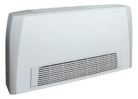
63
Cert. n 0545 Carisma CRC Fan Coil Unit The Ultra Quiet Fan Coil TECHNICAL GUIDE
 Cert. n 0545 www.euroventcertification.com Carisma Fan Coil Unit The Ultra Quiet Fan Coil TECHNCAL GUDE Carisma CONTENTS Construction Page 4 s Page 5 Dimension, Weight, Water content Page 6 EUROENT certification
NEW. Wall controls. YFCN Fan Coil Units. Technical Guide - for internal distribution only
 NEW Wall controls Fan Coil Units www.euroventcertification.com www.certiflash.com Technical Guide for internal distribution only CONTENTS Construction Page 4 s Page 5 Dimension, Weight, Water content Page
CMTE. Tangential Fan Coil Series with Electronic Controlled Motor
 Tangential Fan Coil Series with Electronic Controlled Motor Designed by Very Low Electric Energy Consumption High Efficiency Extremely Low Noise Level Infra Red Remote Control Step-less Fan Speed Control
Carisma CRC. Range includes 9 air rates (from 105 to 1500 m 3 /h) It is the most comprehensive range, perfectly suited to meet
 It is the most comprehensive range, perfectly suited to meet") Carisma CRC Fan Coil Unit with Centrifugal Fan with synchronous Motor Range includes 9 air rates (from to 1500 m /h) and 5 models (for wall and ceiling installation, with casing and concealed), each equipped
Carisma CRC Fan Coil Unit with Centrifugal Fan with synchronous Motor Range includes 9 air rates (from to 1500 m /h) and 5 models (for wall and ceiling installation, with casing and concealed), each equipped
EURUS / EURUS-I. Conditioning your ambient, maximising your comfort.
 EURUS / EURUS-I Centrifugal fan coils for surface mounting or recessed installation. Cooling capacities from 0,6 to 7,6 and heating capacity from 0,8 to 9. Air folw from 0 to 0 m /h. Conditioning your
Technical Catalogue. Cassette Fan Coils Climmy Comfort 3
 Technical Catalogue Cassette Fan Coils Climmy Comfort 3 CONTENTS INTRODUCTION Version Fan Coil Page 3 Page 4 Page 6 Page 7 Page 8 Page 12 Page 13 Page 15 Page 16 Page 18 Page 19 Page 20 Page 22 -ECM Version
Maestro. High Pressure Fan Coil Unit with Asynchronous Motor
 Maestro High Pressure Fan Coil Unit with Asynchronous Motor The Maestro high pressure fan coils are produced in 5 sizes. Designed and built for concealed installations, they have small dimensions, are
CENTRIFUGAL FAN COIL UNIT VCE
 CENTRIFUGAL FAN COIL UNIT VCE 0,51 kw 11,00 kw 0,85 kw 23,75 kw 129 m 3 /h 2003 m 3 /h VCE DESIGN QUALITY COMFORTRELIABILITY 3VERSION12 SIZE DESIGN VCEx0 vertical with cabinet Air intake: bottom vertical
Fans Air Handling Units Air Distribution Products Fire Safety Air Curtains and Heating Products Water terminals SYSCOIL. Centrifugal fan coil units
 Fans Air Handling Units Air Distribution Products Fire Safety Air Curtains and Heating Products Water terminals SYSCOIL Centrifugal fan coil units SYSCOIL Fan coil units Compact, slim fan coil units. Available
MAJOR 2 NCH. Ductable units. High pressure and high capacity ductable units RANGE NCH Y NCH NCH I COADIS COMBI. Motor optional
 Y + U I COADIS COMBI High pressure and high ductable units Motor optional is a non independent air conditioning terminal unit for heating and cooling offices and hotels. With reduced dimensions and designed
Chiller Close Control Water terminals SYSCASSETTE. Water cassette units
 Chiller Close Control Water terminals SYSCASSETTE Water cassette units SYSCASSETTE Water cassette Available accessories Available in 8 different sizes and 2 versions. Due to its square design these units
Ductable Modular Fan Coil Unit VPX. Technical Brochure TM VPX-W.2GB Date : May 2004 Supersedes : TM VPX-W.1GB/08.03
 Ductable Modular Fan Coil Unit VPX Technical Brochure TM VPX-W.2GB Date : May 2004 Supersedes : TM VPX-W.1GB/08.03 Design Features Presentation The VPX fan coil unit has been specially designed to meet
Chiller, Close control and Water terminals. Air Conditioning. Light Commercial, Commercial and Industrial
 Chiller, Close control and Water terminals Air Conditioning Light Commercial, Commercial and Industrial Water Terminals 133 Water Terminals Fan coils & Cassette Centrifugal fan-coil SYSCOIL Ductable fan-coil
Guide Specifications. General. Casing. Coil/Drain pan. Fan/Motor
 Guide Specifications General CR-A series ducted concealed chilled water fan coil units have an air flow range from 45 to 3060 cubic meters per hour with a capacity range from kw up to 9 kw. The CR-A series
Total cooling capacity kw Total heating capacity kw Features
 Room Fan Coils Idrofan Quality Management Systems 42N Total cooling capacity 0.75-6.35 kw Total heating capacity 0.60-9.50 kw The new generation 42N_S product range combines aesthetic and attractive design
Fan coil units MAJOR 2 CV/CH
 CH 41 D CV 1 D MAJOR 2: Design and performance HEE impeller for increased performance Motor optional MAJOR 2 is a non-independant chilled and/or hot water supplied air conditioning Comfort unit for the
something new in the air Technical Bulletin
 something new in the air Technical Bulletin 2 Air Leaf 2 Air Leaf 3 Innova is a company operating in the renewable energy sector and develops advanced climatic comfort systems for every season. The technological
NEW. Wall controls. SkyStar SkyStar ECM Cassette Fan Coil Units. Air Conditioning. Cert. n 0545
 NEW Wall controls Cert. n 04 www.eurovent-certification.com Air Conditioning ECM Cassette Fan Coil Units CONTENTS Introduction Page 3 Main components Page 4 EUROVENT Certifications Page s Page 6 side pressure
Engineering Data Manual. New : available with EC motor. High Static Pressure Ductable Fan Coil Unit. Models 07 to to 4650 m 3 /h
 Engineering Data Manual New : available with EC motor VH High Static Pressure Ductable Fan Coil Unit Models 07 to 27 800 to 4650 m 3 /h General Characteristics Presentation On model VH 07, coils have 4
High Static Pressure Duct Fan Coil Unit
 MCAC-KTSM-2012-03 High static pressure ducted FCU High Static Pressure Duct Fan Coil Unit 1. Introduction... 2 2. Nomenclature... 2 3. Product Schedule... 3 4. External Appearance... 3 5. Features... 4
42GW. Hydronic Cassette Fan Coil Units PRODUCT SELECTION DATA INSTALLATION, OPERATION AND MAINTENANCE INSTRUCTIONS EASY INSTALLATION
 PRODUCT SELECTION DATA EASY INSTALLATION INSTALLATION, OPERATION AND CENTRAL AIR DIFFUSION MAINTENANCE INSTRUCTIONS LOW ENERGY CONSUMPTION IMPROVED COMFORT ELEGANT AIR INLET GRILLE EXTREMELY QUIET OPERATION
BRIZA 22 HYBRID HEATING & COOLING
 BRIZA 22 HYBRID HEATING & COOLING Built-in Ceiling: BABC/BT BABC/FT Built-in Wall: BABW/BT BABW/BF BABW/FT BABW/FF INFO SHEET BRIZA 22 HYBRID, COMPACT FANCOIL With EC Greentech EBM-PAPST technology Europe
Midea 50Hz AC Fan Coil Unit 2-Pipe Floor-standing Series Technical Service Manual
 Midea 50Hz AC Fan Coil Unit 2-Pipe Floor-standing Series Technical Service Manual Midea reserves the right to discontinue, or change specification or designs at any time without notices and without incurring
42N. Room Fan Coils PRODUCT SELECTION DATA. MAINTENANCE INSTRUCTIONS Simpified installation & large options choice
 PRODUCT SELECTION DATA Extremely quiet operation INSTALLATION, OPERATION AND Low Energy Consumption MAINTENANCE INSTRUCTIONS Simpified installation & large options choice Self regulated PTC electrical
Product Data. Features/Benefits. 42BH System Fan Coil. 800 to 4000 Cfm
 Product Data 42BH System Fan Coil 800 to 4000 Cfm Satisfy All Your Design Requirements with Carrier s Versatile 42BH Fan Coil Unit A selection of 6 sizes covers capacities from 800 to 4000 cfm Choice of
FCC DUCTABLE AIR TREATMENT UNIT
 FCC DUCTBLE IR TRETMENT UNIT DUCTBLE IR TRETMENT UNIT FCC 7 different sizes 3, 4 and 6 row coils 2 or 4 pipe system Horizontal installation ductable air treatment unit FCC series The ductable air treatment
Innovative, High Performance, Quiet Units.
 Fan Coil Units Innovative, High Performance, Quiet Units. Technical Brochure TM AQF-A.4GB Date : January 2006 Supersedes : TM AQF-A.3GB/04.04 Quality, efficiency and reliability, built into every unit...
Residential comfort unit OperatiOn 2 models. new builds or existing properties. 5 operating modes COnfOrmity COmpOnents
 Residential HEE motor Silent operation Heating capacity: 200 W to 4 kw Cooling capacity: 100 W to 3 kw Operation is CIAT's residential. This vertical cased unit, designed for heating and cooling, is available
42C/D SERIES Ducted Chilled Water Fan Coil Unit With District Cooling Application
 42C/D SERIES Ducted Chilled Water Fan Coil Unit With District Cooling Application MAXIMIZING PERFORMANCE, ENERGY SAVINGS & COMFORT MODEL NUMBER NOMENCLATURE 4 2 C E T 0 0 3 4 7 0 1 2 5 42 series CISB Code
1 AIR HANDLING UNIT TYPE AIR ACCESS 75
 SUPPLY 1 AIR HANDLING UNIT TYPE AIR ACCESS 75 Location : EXTERNAL Position : SIDE BY SIDE SLIDING PANELS for COMPLETE ACCESSIBILITY MULTI SERVICE BULKHEAD for HYDRAULIC AND ELECTRICAL CONNECTIONS Self-supporting
V33B High Efficiency 360 Cassette Indoor Models - 60HZ
 PRODUCT SPECIFICATIONS Low-sound, high efficiency cassette, encased in galvanized steel offers 360 airflow for immediate, equal distribution of wide-range cooling and heating. Cassette has motor-driven
UTA STANDARD. Ductable units. Range. Air handling unit with high available static pressure. NEW Eco-Design Filter. V3000 control Fresh air management
 Ductable units NEW Eco-Design Filter Air handling unit with high available static pressure V3000 control Fresh air management The range of air handling units is designed for suspended ceiling heating and
FCX TECHNICAL BOOKLET
 FAN COIL FCX US FCX USPO This document is based on AERMEC s FCX US, USP, USPO Technical and Installa on Booklet but reflects only those sizes and configura ons currently offered by Phoenix Energy Supply.
Fan coil units. Why choose Daikin fan coil units? 540 Products overview 542. Options & accessories 560. Round flow cassette 544 FWC-BT/BF 544
 Fan coil units Why choose Daikin fan coil units? 540 Products overview 542 Round flow cassette 544 FWC-BT/BF 544 4-way blow ceiling mounted cassettes 545 FWG-AT/AF 545 FWF-BT/BF 546 FWF-CT 547 Floor standing
Driving and Connecting Globally. Fan Coil Unit. Model : PHW-K Size : 510CMH~2720CMH. Made in Taiwan
 Driving and Connecting Globally Fan Coil Unit : PHW-K Size : 510CMH~2720CMH Made in Taiwan Features Superior low-height design. Stainless steel drain pan for condensate and corrosion protection. Flexibe-reverse
42CET/ 42CED Series Chilled Water Fan Coil Unit Furred-in Ceiling Model 300 to 1400 cfm Electric heater option
 42CET/ 42CED Series Chilled Water Fan Coil Unit Furred-in Ceiling Model 0 to 10 cfm Electric heater option 42DC/ 42DCD Series Chilled Water Fan Coil Unit Furred-in Ceiling Model 0 to 00 cfm Electric heater
VLH 504 to Air-to-Water Reverse Cycle Heat Pumps. 126 to 294 kw. 133 to 307 kw
 Air-to-Water Reverse Cycle Heat Pumps VLH 504 to 1204 126 to 294 kw 133 to 307 kw Technical Brochure TM VLH-N.3GB Date : June 2005 Supersedes : TM VLH-N.2GB/07.04 Specifications Advantages Range extension
Address: VTS Clima L.L.C.
 Address: VTS Clima L.L.C. Business Bay, Churchill Tower, Office 2409, P.O.Box#76849 Dubai, UAE phone: +971 (4) 443 91 20 fax: +971 (4) 443 96 20 e-mail: dubai@vtsgroup.com www.uae.vtsgroup.com Index VTS
Fan coil units. HFCE, HFXE, VFCE, VFXE series Sizes 03 to to 3400 m3/h UNT-PRC007-E4
 Fan coil units HFCE, HFXE, VFCE, VFXE series Sizes 03 to 20-300 to 3400 m3/h 2012 Trane Contents Features and Benefits 4 Model Nomenclature 5 Performance Data 7 Capacities 9 Dimensional data 19 Typical
The World Leading Air-conditioning Company
 The World Leading Air-conditioning Company Table of Contents DESCRIPTIONS Model Number Nomenclature Features & Benefits Physical Dimension Fan Performance Curve (4 Row) - 40LMA024 with AC Motor - 40LMA040
TECHNICAL MANUAL ESTRO BLDC ESTRO BLDC FAN COILS - BRUSHLESS TECHNOLOGY. 1.5 kw kw
 GB TECHNICAL MANUAL ESTRO BLDC ESTRO BLDC FAN COILS - BRUSHLESS TECHNOLOGY 1.5 kw - 9.0 kw TABLE OF CONTENTS 1 Generalities... 3 2 Models and constructive components...4-5 3 Accessories available... 6
Air-Cooled Liquid Chiller with integrated hydraulic module
 Air-Cooled Liquid Chiller with integrated hydraulic module Cooling only: CGAN 200-250 - 300-400 - 450-490 - 500-600 - 700-800 - 900-925 Reversible: CXAN 200-250 - 300-400 - 450-490 - 500-600 - 700-800
VMDA Concealed Medium Static Ducted Indoor Models - 60HZ
 VARIABLE REFRIGERANT FLOW SYSTEMS VRF VMDA Concealed Medium Static Ducted Indoor Models - 60HZ PRODUCT ECIFICATIONS Slim, compact design for limited space requirements. Installs out of sight between the
FCVC Series VERTICAL FAN COILS
 VERTICAL FAN COILS The FCVC is designed for concealed, wall mounted installations with flexible heating/ cooling loads and minimal duct requirements. With a variety of options, such as fiber free insulation,
V33A Standard/High Efficiency 360 Cassette Indoor Models - 60HZ
 PRODUCT SPECIFICATIONS Low-sound, standard or high efficiency cassette, encased in galvanized steel offers 360 airflow for immediate, equal distribution of wide-range cooling and heating. Cassette has
YFCN Fan Coil Unit centrifugal fan 2 & 4 pipe system A complete range from 1.0 kw to 7.6 kw
 Fan Coil Unit centrifugal fan 2 & 4 pipe system complete range from 1.0 kw to 7.6 kw Water Systems Wired controls R Remote three speeds controller TR R + Electronic thermostat and Summer/Winter switch
VMDB Concealed Medium Static Ducted Indoor Models - 60HZ
 VARIABLE REFRIGERANT FLOW SYSTEMS VRF VMDB Concealed Medium Static Ducted Indoor Models - 60HZ PRODUCT ECIFICATIONS Bulletin No. 210711 March 2018 Slim, compact design for limited space requirements. Installs
SysCoil 2. Fan Coil Units Models SVC, SVN, SHC, SHN to 8.75kW to 4.90kW. 94 to /h
 SysCoil Fan Coil Units Models SVC, SVN, SHC, SHN 0.79 to 8.75kW 0.49 to 4.90kW 94 to 930 3 /h SysCoil Quality, efficiency and reliability Vertical console units with cabinet, SVC type SVC vertical console
CHP
 Packaged Unit Heat Pump CHP16-024-030-036-048-060 2-5 Ton Cooling 23,000-57,500 Btuh Heating 12,800-85,300 Btuh (5-25 kw) Optional Electric Heating FEATURES Designed for outdoor rooftop or ground level
VHIA High-Static Ducted Indoor Units - 60HZ
 PRODUCT SPECIFICATIONS Compact design for limited space requirements. Installs out of sight between the drop ceiling and ceiling slab with ducted distribution to the indoor space. All models have three-stage
Versatility. Features. By installing the SILENT MV, you will never experience the disturbance of noisy ventilation again. Benefits
 Ultra quiet and low profile helicocentrifugal in-line fans suitable for a wide range of domestic and commercial applications. Fitted with sound absorbent insulation and manufactured with an adjustable
Prepared By : Checked By : Approved By : Page 1 out of 6
 Software Name Carrier AHU - Version 1.0, Patch R1.1X UNIT MODEL GENERAL SPECIFICATIONS GENERAL LOCATION / WEIGHT UNIT DIMENSION Configuration : Quick Selection Wizard Unit Orientation : Horizontal Box
GENERAL ELECTRIC CONCEALED CHILLED WATER FAN COIL UNITS
 GENERAL ELECTRIC CONCEALED CHILLED WATER FAN COIL UNITS ACWL Series ACWL0 thru ACWL4 00 CFM thru 400 CFM GE_ACWL_series.indd 3// : PM CONTENTS Model decoding 3 Unit features 3 Standard specifications 3-4
Concealed Ducted Split Series R22
 Concealed Ducted Split Series R22 24-60 MBH Ducted Split with Hermetic Compressor Tropical 50 Hz For more technical information please visit Table of Contents INTRODUCTION 2 NOMENCLATURE 2 UNIT RATING
PVHRU Max Quiet. Engineering Solutions. Packaged Void Heat Reclaim Unit. Acoustic Testing Laboratory College of Science & Technology
 AIR HANDLERS LTD PVHRU Max Quiet Packaged Void Heat Reclaim Unit 1262 Acoustic Testing Laboratory College of Science & Technology Engineering Solutions The Company Air Handlers has been trading since May
technical sales guide - 60Hz Ducted Split Units HIGH AMBIENT OPERATION 52 UPTO
 technical sales guide - 60Hz Taurus R Ducted Split Units UPTO HIGH AMBIENT OPERATION 52 O C Page CONTENTS Nomenclature.. 2 Description. 3 Features.. 3 Product Data. 4 Condensing Unit Cooling Performance
SLH 1202 to Air-to-Water Reverse Cycle Heat Pumps. With Screw Compressors. 261 to 775 kw. 287 to 853 kw
 Air-to-Water Reverse Cycle Heat Pumps SLH 1202 to 3804 With Screw Compressors 261 to 775 kw 287 to 853 kw Technical Brochure TM SLH-A.2GB Date : November 2004 Supersedes : TM SLH-A.1GB/05.04 Design Features
BRIZA EC 12 HYBRID. World s slimmest fan coil HEATING AND COOLING
 World s slimmest fan coil wall and ceiling installation 2-or 4-Pipe system heating and / or cooling with or without enclosure easy installation 24VDC EC motor silent, powerful, economical, sustainable
MH1WC4W-08-1-B Chilled/Hot Water 1-Way Cassette Fan Coil
 MH1WC4W-08-1-B Chilled/Hot Water 1-Way Cassette Fan Coil 4-Pipe Heat / Cool Fan Coil 24,000 BTUH Rev. 1.11 HVAC Guide Specifications Chilled and Hot Water Cassette Fan Coil 4-Pipe Nominal Size: 24,000
Complete HVAC Capability
 Air Handling Units Brochure 1110 January 2006 Complete HVAC Capability MEA Horizontal Draw-Thru to Size 65 Vertical Draw-Thru to Size 50 1000 to 60,000 CFM Forward Curved or Airfoil Wheels Inlet Vane Option
CLIMA CANAL HYBRID HEATING AND COOLING CLIMA CANAL. Compact floor recessed fancoil unit HEATING
 Compact floor recessed fancoil unit CLIMA CANAL HEATING AND COOLING: Build-in height of 3.94 > 5.71 CLIMA CANAL HEATING ONLY: Build-in height of 3.35 > 5.43 electronic control: 0...10V signal 24V EC motor
^áêëçåâ=ìåáí=åççäéêë=qvoj^ pí~åç~êç=åççäéêë=ïáíü=pí~áåäéëë=píééä=íìäáåö
 ^áêëçåâ=ìåáí=åççäéêë= pí~åç~êç=åççäéêë=ïáíü=pí~áåäéëë=píééä=íìäáåö O `çåíéåíë= page Model indication................................ 2 Eurovent...................................... 2 Capacities.....................................
BUILDING EFFICIENCY Energy Efficient Variable Speed EC Motor Fan Coil Unit Solutions Model YECFC
 BUILDING EFFICIENCY Energy Efficient Variable Speed EC Motor Fan Coil Unit Solutions Model YECFC Product Introduction INTRODUCTION Johnson Controls YORK YECFC fan coil units are high efficiency, low profile,
SILENT MV Ultra Quiet In-line Fans
 Ultra Quiet In-line Fans 5 IP44 2 YEAR GUARANTEE Ultra quiet and low profile helicocentrifugal in-line fans suitable for a wide range of domestic and commercial applications. Fitted with sound absorbent
ROOF TOP (SERIES SR) 10.8 TO 103 KW 37,000 TO 351,000 Btuh
 10.8 TO 103 KW 37,000 TO 351,000 Btuh") ROOF TOP (SERIES ) 10.8 TO 103 KW 37,000 TO 351,000 Btuh These rooftop units are complete, self contained air conditioners fully assembled, wire, charged and tested prior to shipment, each unit is delivered
ROOF TOP (SERIES ) 10.8 TO 103 KW 37,000 TO 351,000 Btuh These rooftop units are complete, self contained air conditioners fully assembled, wire, charged and tested prior to shipment, each unit is delivered
TECHNICAL GUIDE R410a SPLIT SYSTEM 1.5 to 5.0 NOMINAL TONS
 Version.MDT-2016.T3.103 TECHNICAL GUIDE R410a SPLIT SYSTEM 1.5 to 5.0 NOMINAL TONS FEATURES AND BENEFITS COMPRESSOR: Compressors are protected with internal temperature and current overloads. An internal
CLOSE CONTROL UNITS WITH CHILLED WATER COIL
 CLOSE CONTROL UNITS WITH CHILLED WATER COIL COOLING CAPACITY FROM 5 TO 154 kw 230 D 56 The range of chilled water close control units, series, is particularly indicated for use in technological centres,
Midea Air Handling Unit
 Midea Air Handling Unit Floor mounted 3000CFM ---25000CFM Vertical mounted 3000CFM ---25000CFM Ceiling suspended 1000CFM ---9000CFM Midea reserves the right to improve the product and technology without
WE MAKE INDOOR AIR BETTER
 WE MAKE INDOOR AIR BETTER Water-Cooled Heat Pumps & Air Conditioners /4-Ton to 60-Tons Various voltages/phases Suitable for duct connections Ideal for use with free air supply plenum (2-axis adjustable
Commercial Blower Coil Air Handlers
 Commercial Blower Coil Air Handlers MODEL : BDH(V)B - 048, 065, 080 7400 CMH - 14300 CMH 30 kw - 125 kw BCXB-PRC001-E4 Contents Model Number Description General Specification Standard Features Unit Configuration
Product Catalogue ARMONIA Providing indoor climate comfort
 Product Catalogue ARMONIA Providing indoor climate comfort ARMONIA 1,3-11 kw Water cassette Main applications Light commercial buildings Offi ces Shops General description Why this choice? Silent operation
Air Cooled Water Chillers. CLS 182 to to 150 kw. Technical Brochure TM CLS-W.3GB Date : October 2004 Supersedes : TM CLS-W.2GB/07.
 Air Cooled Water Chillers CLS 182 to 602 41 to 150 kw Technical Brochure TM CLS-W.3GB Date : October 2004 Supersedes : TM CLS-W.2GB/07.04 R Specifications General characteristics The CLS air cooled water
D M S 760 C01 A A 1 1
 CONTENTS Description Features Options Available Selection Method Product Data Cooling Performance Data (85 F Ambient Cooling Performance Data (95 F Ambient) Cooling Performance Data (105 F Ambient)..............................
MHWW-24-H-1 Chilled/Hot Water Hi-Wall Fan Coil. Heat / Cool Fan Coil 24,000 BTUH. Rev. 1.3
 MHWW-24-H-1 Chilled/Hot Water Hi-Wall Fan Coil Heat / Cool Fan Coil 24,000 BTUH Rev. 1.3 HVAC Guide Specifications Chilled and Hot Water Hi-Wall Fan Coil 2-Pipe Nominal Size: 24,000 BTUH Multiaqua Model
Fan Coil Units. Technical Data ECDEN FWL-DT/DF
 Fan Coil Units Technical Data ECDEN10-400 FWL-DT/DF Fan Coil Units Technical Data ECDEN10-400 FWL-DT/DF TABLE OF CONTENTS FWL-DT/DF 1 Features.............................................................
AHN 064 to 304 EHN/CHN 064 to 304
 u Horizontal Packaged and Split Air Conditioners AHN 64 to 34 EHN/CHN 64 to 34 6. to 29.2 kw 6.4 to 29.4 kw Engineering Data Manual EDM AECHN-A.1GB Date : June 28 Supersedes : None Technical Description
Water terminals from 91 to 1548 m 3 /h. from 0,5 to 9,6 kw. SysCoil Comfort. Floor and ceiling fan coil units. from 0,6 to 13,6 kw
 Water terminals from 91 to 1548 m 3 /h SysCoil Comfort Floor and ceiling fan coil units from 0,5 to 9,6 kw from 0,6 to 13,6 kw SysCoil Comfort Innovation for an optimum comfort ErP 2018 TERTIAIRY H 3 /h
R410A TECHNICAL MANUAL. Inverter Single Split Series Air Conditioner. FTK-J, FTXN-J Series. Cooling only & Heatpump [50Hz] TM-5WMY-J-ST-A2
![R410A TECHNICAL MANUAL. Inverter Single Split Series Air Conditioner. FTK-J, FTXN-J Series. Cooling only & Heatpump [50Hz] TM-5WMY-J-ST-A2](/thumbs/87/97223604.jpg "R410A TECHNICAL MANUAL. Inverter Single Split Series Air Conditioner. FTK-J, FTXN-J Series. Cooling only & Heatpump [50Hz] TM-5WMY-J-ST-A2") R410A TECHNICAL MANUAL Inverter Single Split Series Air Conditioner FTK-J, FTXN-J Series Cooling only & Heatpump [50Hz] TM-5WMY-J-ST-A2 Table of Contents Table of Contents Nomenclature...1 Indoor...1 Outdoor...1
R410A TECHNICAL MANUAL Inverter Single Split Series Air Conditioner FTK-J, FTXN-J Series Cooling only & Heatpump [50Hz] TM-5WMY-J-ST-A2 Table of Contents Table of Contents Nomenclature...1 Indoor...1 Outdoor...1
fåçìëíêá~ä=~áê=åççäéêë=qvo pí~åç~êç=åççäéêë=ïáíü=ëí~áåäéëë=ëíééä=íìäáåö
 fåçìëíêá~ä=~áê=åççäéêë= pí~åç~êç=åççäéêë=ïáíü=ëí~áåäéëë=ëíééä=íìäáåö O `çåíéåíë= page Model indication..................................2 Eurovent.......................................2 Capacities......................................2
ERP 2015 Regulation (EU) Compliant with. No. 327/2011. Cert. n Heating. Meltemi Door Curtains
 Compliant with. No. 327/2011. Cert. n Heating. Meltemi Door Curtains") Compliant with ERP 015 Regulation (EU) No. 7/011 Cert. n 0545 Heating Door Curtains The range of SBIN door curtains offers imum flexibility in the protection of doors and open access compartments. By connecting
Compliant with ERP 015 Regulation (EU) No. 7/011 Cert. n 0545 Heating Door Curtains The range of SBIN door curtains offers imum flexibility in the protection of doors and open access compartments. By connecting
TECHNICAL MANUAL SOFFIO Ducted units
 TECHNICAL MANUAL SOFFIO Ducted units Page 1 INDEX 1-INTRODUCTION... 4 2-OPERATING LIMITS... 4 3- KEY TO READING CODES... 5 4-TECHNICAL SPECS... 6 5-TECHNICAL DATA (AC motors)... 7 5.1-Unit 2 pipes with
42NL & 42NH. Hydronic Ducted Fan Coil Units PRODUCT SELECTION DATA. Modular Horizontal ducted unit. Extremely quiet operation. Low Energy Consumption
 PRODUCT SELECTION DATA Modular Horizontal ducted unit Extremely quiet operation Low Energy Consumption Flexibility for simplified installation Improved comfort Efficient Indoor Air Quality Hydronic Ducted
Silent centrifugal air heater hot water supply
 Large range : 5 to 120 Flows : 900 to 14000 m 3 /h Numerous accessories Design integrating perfectly in public buildings USE Operation in zones ES and S Extra silent and silent Forced air heating for premises
BASTONE (dual) fancoil Units
 fancoil Units") BASTONE (dual) fancoil Units Technical information manual Western Airconditioning B.V. Tel. +31 (0) 33 247 78 00 www.western.nl 1-INTRODUCTION..3 2- WORKING CONDITION LIMITS...3 3- COANDA EFFECT 3 4- KEY
BASTONE (dual) fancoil Units Technical information manual Western Airconditioning B.V. Tel. +31 (0) 33 247 78 00 www.western.nl 1-INTRODUCTION..3 2- WORKING CONDITION LIMITS...3 3- COANDA EFFECT 3 4- KEY
VERTICAL SINGLE AND DOUBLE WALL BELT DRIVE AIR HANDLER DX OR CHILLED WATER COOLING WITH HOT WATER OR ELECTRIC HEAT
 VERTICAL SINGLE AND DOUBLE WALL BELT DRIVE AIR HANDLER DX OR CHILLED WATER COOLING WITH HOT WATER OR ELECTRIC HEAT SIZES FROM 600 TO 4,000 All Technical Specifications are Subject to Change without Notice.
Chilled Water FCU. Horizontal Fan Coil 50hz CFM. A Series.
 Chilled Water FCU A Series 3-25 CFM Horizontal Fan Coil 5hz www.windind.com CONTENTS GENERAL CONSTRUCTION... 3 MODEL NUMBER NOMENCLA TURE... 4 DIMENSIONS... 5 FAN PERFORMANCE DATA... 7 GENERAL SPECIFICATIONS...
VWMB Wall-Mounted Non-Ducted Indoor Models - 60HZ
 PRODUCT SPECIFICATIONS VARIABLE REFRIGERANT FLOW SYSTEMS VRF VWMB Wall-Mounted Non-Ducted Indoor Models - 60HZ Bulletin No. 210712 March 2018 Low-sound, three-speed Wall Mount with LED display offers three
Systempac. Fan Coil Unit / Acoustic Flex / Diffuser System Package. Systempac. January Features and Design Guide
 January 2002 Systempac Features and Design Guide Specifically Designed for Design and Build Projects. Complete package including Waterside Control Fan Coil Unit / Controls / Flexible Ducting / Plenum Box
fåçìëíêá~ä=~áê=åççäéêë=qelo pí~åç~êç=åççäéêë=ïáíü=`ì=íìäáåö
 = pí~åç~êç=åççäéêë=ïáíü=`ì=íìäáåö O `çåíéåíë= page Model indication..................................2 Eurovent.......................................2 Capacities......................................2
product selection data Slim design Acoustic comfort 40% smaller footprint Drycoolers 09VE
 product selection data Slim design Acoustic comfort 40% smaller footprint Drycoolers 09VE Translation of the original document N 20033, 03.2015 Drycoolers Use Drycoolers in this range are mainly designed
Precision Cooling For Business-Critical Continuity. Liebert CW. System Design Manual kW, 50 & 60Hz
 Precision Cooling For Business-Critical Continuity Liebert CW System Design Manual - 26-181kW, 50 & 60Hz TABLE OF CONTENTS LIEBERT CW MODEL NUMBER NOMENCLATURE....................................1 1.0
Water terminals From 360 to 1598 m 3 /h. From 1.3 to 9.6 kw. SysQuare. Chilled water cassettes. From 1.1 to 14.0 kw
 Water terminals From 360 to 1598 m 3 /h SysQuare Chilled water cassettes From 1.3 to 9.6 kw From 1.1 to 14.0 kw SysQuare The best way to combine low noise and energy savings 6 sizes (20, 30, 40, 50, 60
42NL & 42NH. Hydronic Ducted Fan Coil Units PRODUCT SELECTION DATA. Modular Horizontal ducted unit. Extremely quiet operation
 PRODUCT SELECTION DATA Modular Horizontal ducted unit Extremely quiet operation Low Energy Consumption Flexibility for simplified installation Improved comfort Effcient Indoor Air Quality Hydronic Ducted
HRS. Very high efficiency heat recovery units. from 300 to m³/h >90 % WITH HIGH EFFICIENCY HEAT RECOUPERATOR
 4 Lmf Clima 6 FERRARO GROUP HRS Very high efficiency heat recovery units WITH HIGH EFFICIENCY HEAT RECOUPERATOR from 3 to 4. m³/h Air-handling unit designed and manufactured for nonresidential applications,
CHILLED WATER FAN-COIL UNITS
 40LM - PRODUCT DATA DIGEST CHILLED WATER FAN-COIL UNITS QUALITY SYSTEM MALAYSIA MS ISO 001 REG. NO: AR 023 1 Any room, every room flexibility in an air conditioning system FEATURES: Chilled Water Furred-in
Modular Air Handling. Up to 3,500 Litres / sec. Low profile & Plant room application. Draft. Version. Second Edition A-. AirDesign 2015 AirDesign 2016
 Modular Air Handling U n i t R a n g e Up to 3,500 Litres / sec Low profile & Plant room application AirDesign 2015 AirDesign 2016 Second Edition Draft Version A-. Air Design is a proud Australian based
HBC SERIES-PSC MOTOR HBCX SERIES-ECM MOTOR
 PRODUCT SPECIFICATIONS *HBC(X) *PHBC(X) *RHBC(X) *CHBC(X) Chilled Water/Hot Water 2-pipe/4-Pipe HBC SERIES- HBCX SERIES-ECM MOTOR Ceiling Concealed Horizontal -1 CFM Ceiling Concealed Ceiling Recessed
SPLIT DUCTED UNIT SCA300C / SCA300E TECHNICAL SELECTION DATA SPECIFICATION SUMMARY UNIT FEATURES CONTROL OPTIONS UNIT COMPLIANCE
 TECHNICAL SELECTION DATA SPLIT DUCTED UNIT 3 THREE PHASE SCROLL TWO STAGE CENTRIFUGAL LOUVRE AXIAL UNIT FEATURES Scroll Compressor Multiple Speed Outdoor Fans Louvred Outdoor Coil Guard Pre-charged with
Chiller. AQL/AQH 40 to 75. Air Cooled Water Chillers Cooling Only and Heat Pump Engineering Data Manual to 77.2 kw to 75.
 Chiller AQL/ to 75 Air Cooled Water Chillers Only and Heat Pump Engineering Data Manual.0 to 75.8 kw 39.9 to 77.2 kw Outstanding Strength Points R410A Refrigerant. New simpler refrigerant circuit layout.
Dual discharge air coolers THOR-D. Standard coolers in a revolutionary design
 Dual discharge air coolers THOR-D Standard coolers in a revolutionary design O jççéä=áåçáå~íáçå `çåíéåíë= page Model indication................................ 2 Eurovent......................................