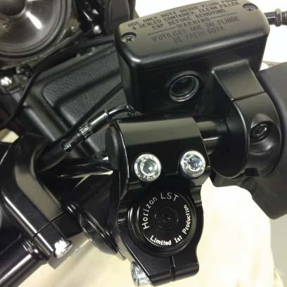
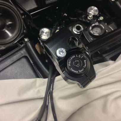
Horizon LST Installation Photos Honda GL F6B Bagger P/N: LST01084
|
|
|
- Christiana Rogers
- 5 years ago
- Views:
Transcription

1 Horizon LST Installation Photos Honda GL F6B Bagger P/N: LST01084 IMPORTANT: PLEASE GIVE CUSTOMER ENCLOSED INFORMATION!
2 Thank you for your HeliBars purchase. HeliBars are designed to increase your long distance comfort and improve the handling of your motorcycle, and we feel confident you will enjoy them. The Horizon LST is the most technologically advanced handlebar system to ever grace a motorcycle. Many saftey features have been included in the design. It is of the utmost importance the bars are installed by a mechanic with good mechanical skills following the installation instructions provided. HeliBars INSTALLATION DANGER: IMPROPER INSTALLATION COULD RESULT IN SERIOUS INJURY OR DEATH. HAVE A QUALIFIED MECHANIC INSTALL YOUR HeliBars. BRAKE FLUID CAN BE CORROSIVE TO PLASTIC & PAINT. PLEASE USE CAUTION WHEN WORKING WITH YOUR HYDRAULIC SYSTEMS. ENSURING ALL WORK AREAS ARE PROTECTED. AFTER INSTALLATION, MOVE BARS LOCK TO LOCK AND CHECK CLEAR- ANCE OF: 1.CABLES 2. HYDRAULIC LINES 3.WIRES 4.FAIRING 5.FUEL TANK. TORQUE ALL HARDWARE TO MANUFACTURER S SPECIFICATIONS. IF YOU HAVE INSTALLATION QUESTIONS, PLEASE CALL Page 2 Updated:
3 WARRANTY / RETURN POLICY We make every effort to build a quality product so you can fully enjoy your riding experience. Thank you for your order. HeliBars may be returned for defects in materials and workmanship within one year from the date of shipment to the original purchaser, in which event the purchaser may receive a replacement set of Heli- Bars. If within thirty (30) days of the shipping date you are not satisfied for any reason, you can return the HeliBars. Return policy is valid for original purchaser only. If HeliBars are purchased from a vendor other than Heli Modified, Inc., customer must contact vendor where purchased regarding returns. Refund will be extended to original purchaser only. There are no other warranties which extend beyond this. Conditions of this 30 day return policy: 1. Bars must not be used as a tie down point. (See attached Trailering Instructions ). 2. Bars cannot be damaged, dented, or altered in any way. 3. Bars cannot be overtorqued. 4. Refund will be for product purchase price only, and credited to original purchaser only. 5. Product must be returned with all original equipment, documents and in original packaging. There must be no physical damage caused by the customer or by carrier. 6. A Return Authorization Number must be obtained from us before you return the product. We reserve the right to charge a re-stocking fee of up to 25% if the above criteria are not met. THERE ARE NO FURTHER EXPRESS OR IMPLIED WARRANTIES INCLUDING, BUT NOT LIMITED TO, IMPLIED WARRANTIES OF MERCHANTABILITY OR FITNESS FOR A PARTICULAR PURPOSE. By accepting this product, the consumer agrees to arbitrate and litigate any controversy in the State of Maine, and under the laws of the State of Maine. HELI MODIFIED INC. ASSUMES NO LIABILITY FOR ANY INJURY OR LOSS OF PROPERTY WHICH RESULT FROM IMPROPER INSTALLATION OR USE OF ANY HELI BARS. ALL HELI MODIFIED, INC. PRODUCTS SHOULD BE INSTALLED BY A QUALIFIED MECHANIC. IMPROPER INSTALLATION MAY CAUSE DEATH OR INJURY. Ride Safe and Enjoy! Page 3 Updated:
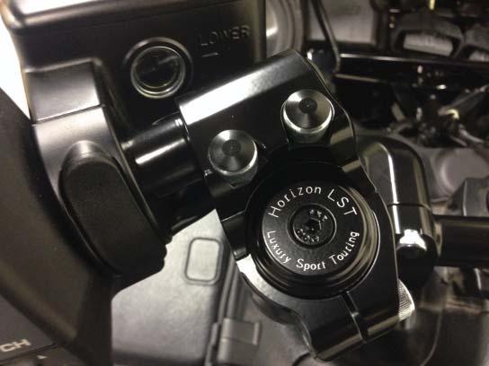
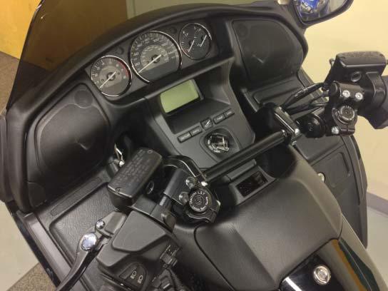
4 Installation Photos Honda GL1800 & F6B Horizon LST Installation P/N: LST01084 Height: Up to 2.5 ~ Set Back: Up to 4 inches ~ Wrist Angle Adjustments: 36 Degree Sweep Installation Overview: While installation on GL1800 and F6B Baggers are basically identical, specific instructions pertinent to the Goldwing/F6B Deluxe Models are highlighted in RED. 1.) Place a protective cover over fuel tank and fairing to protect painted surfaces. Use of the factory service manual is highly recommended to aid in installation. 2.) The clutch and front brake hydraulic line extension adapters MUST BE INSTALLED BEFORE the stock bars are removed. It is not possible to install them with the Horizon LST system in place as the master cylinders will not reach the new bar position. 3.) Tools: All hardware on the LST Handlebar system is metric. An accurate torque wrench is required, as well as drives, to perform installation and for torquing pinch bolts after adjustments are made. Required Tools: 1/4 & 1/2 drive ratchet 14MM, 12MM & 8MM Sockets 13MM, 12MM & 8MM Wrenches 5MM/6MM/8MM Hex (Allen) Drive A complete Metric Allen Set Phillips Screw Driver Long Thin Spade Screw Driver Paper Towels Clean Shop Rags DOT 4 Brake Fluid Page 4

5 Page 5 Updated:
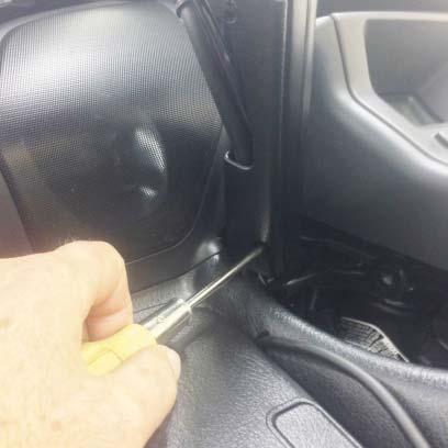
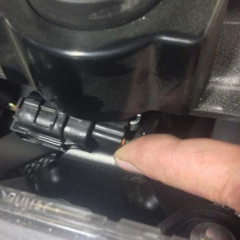
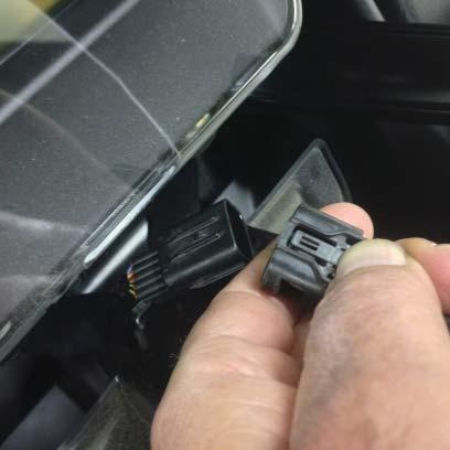
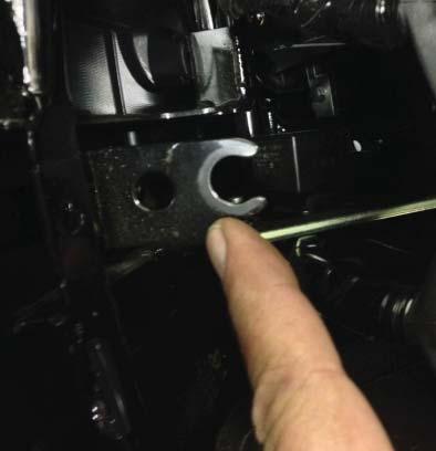
6 Installation Overview: While installation on GL1800 and F6B Baggers are basically identical, specific instructions pertinent to the Goldwing/F6B Deluxe Models are highlighted in RED. 1.) Place a protective cover over fuel tank and fairing to protect painted surfaces. Use of the factory service manual is highly recommended to aid in installation. 2.) The clutch and front brake hydraulic line extension adapters MUST BE INSTALLED BEFORE the stock bars are removed. It is not possible to install them with the Horizon LST system in place as the master cylinders will not reach the new bar position. 3.) Tools: All hardware on the LST Handlebar system is metric. An accurate torque wrench is required, as well as drives, to perform installation and for torquing pinch bolts after adjustments are made. Required Tools: 1/4 & 1/2 drive ratchet 14MM, 12MM & 8MM Sockets 13MM, 12MM & 8MM Wrenches 5MM/6MM/8MM Hex (Allen) Drive A complete Metric Allen Set Instructions: 1.) Remove bar end damper weights (See Photo #1) from the ends of both handlebars. 2.) Remove the plastic covers from the back sides of the handlebars. A. Turn the handlebars all the way to the right until the forks contact the stop. This will allow access to the lower screws on the left bar. Use a Phillips screw drive that is in good condition, loosen and remove screw. (See Photo #2 & 3) B. Loosen and remove upper screw. Remove cover and set aside. C. Repeat on the right bar by turning the forks all the way to the left steering stop. Release the throttle cables from the clip on the right cover to remove. Store covers as they will not be re-used. 3.) Remove dash. It is highly recommended to understand the proper removal procedure outlined in the factory service manual. A. Starting at the ignition area, pry up the dash to release. (See Photo #4) B. Pull the upper dash back until it releases, grabbing outside the speaker grills. C. Carefully reach behind the speaker grills, peel back the rubber boots and release the connector to the tweeters on each side. The tabs to release the connectors are facing the instrument gauges. CAUTION: DO NOT contact speakers with your knuckles as they can be damaged! (See Photo #5 & #6) D. Release center connector at ignition area. (See Photo #7 & #8) Push the connector towards the right side of the bike until it releases from its mounting tang. (See Photo #9) This will allow more slack to separate the connector. Set dash aside out of the way. 4.) Instruments: ( Note: On , skip this step as it s not required.) A. Loosen and remove the 4 bolts, (2 per side), that mount the instrument cluster. (See Photo #10) Use an 8MM socket. The upper left and right bolts have larger washers under them. Page 6 Updated:
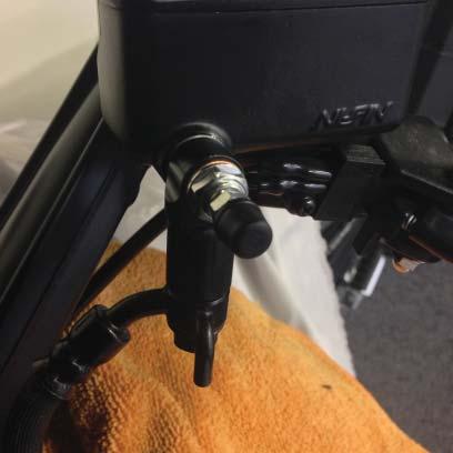
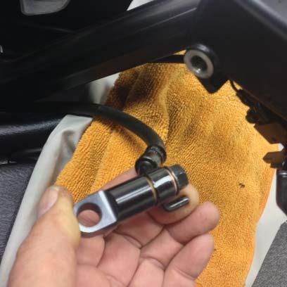
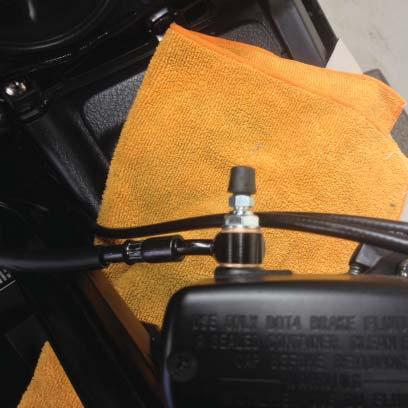
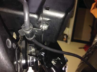
7 B. Pull up the instrument housing (closest to the ignition) while pushing down near the top and pull the unit swing the unit up and hold in place with a bungee cord hook or tie down using one of the lower mounting holes and the windshield. (See Photo #11) 5.) Install hydraulic line adapters. (See Photo #16) for parts required. A. Place a rag directly under the clutch master cylinder. (Do NOT remove reservoir cover at this time.) B. Loosen and remove the clutch hydraulic line from the clutch master cylinder. Very little fluid will drain. Remove and discard the sealing washers. Clean the stock banjo bolt and the banjo fitting of brake fluid. C. Place a new copper washer (provided) over the stock banjo bolt, slide it through the opposite end of the banjo fitting, then place a second washer over the banjo bolt and thread the adapter until it contacts the washer. (See Photo #17) DO NOT TIGHTEN AT THIS TIME. D. Take one of the bleeder banjo bolts provided and put a copper washer in place. Insert it through the hole in the top of the adapter followed by the final washer. Thread the bleeder banjo into the clutch master cylinder. (See Photo #18) Hold the adapter vertical with one hand as you tighten the bleeder banjo bolt. It may take several tries to tighten and keep the adapter vertical. E. Rotate the hydraulic line as shown in ( Photo #19). Hold the fitting while tightening the lower banjo bolt. View is straight down over master cylinder. Tighten bleeder bolt. Use caution to not strip bleeder! (See Photo #20) F. Repeat steps A-E on the front brake master cylinder. (See Photo #21) for hydraulic line rotational position. Tighten. DO NOT BLEED MASTER CYLINDER AT THIS TIME. Make sure all banjo bolts are tight. 12 ft lbs. G. Loosen the two bolts that hold the hydraulic line/wire loom stay in place. (See Photo #22) Use an 8MM socket. H. Pull the clutch & hydraulic lines and wire loom grommets back and release them from the stay. (See Photo #23) Retighten the stay bolts. On GL1800 leave the two heated grip leads in their stock position. I. Place a small cable tie (provided) in front of the stay and tighten firmly. Cut off excess. (See Photo #24) for clarity. Put a cable tie on both hydraulic lines and both wire looms. 6.) Remove the stock right handlebar A. Remove the right bar first. Remove the black plastic clip that covers the master cylinder clamp. Loosen and remove the two socket head cap screws. Use a 5MM hex (Allen). Remove Cap. (See Photo #25) B. Loosen and remove the two screws holding the two halves of the throttle housing together. They are accessed from the bottom. (See Photo #26) One in front and one in back. Lower the bottom half of the housing. Use a Phillips screw driver. C. Loosen and remove the screw holding the inner strap in place. The strap will pivot down but stay in place. (See Photo #27) D. Loosen and remove the two 10MM flange head bolts. Use a 14MM socket and extension. Support the handlebar as the mounting bolts are removed. Slide the bar out of the throttle housing and rest the controls on a rag. (See Photo #28 & #29) E. Repeat step A on the left handlebar and let the clutch master cylinder rest on the rag on the fairing. (See Photo #30) F. Remove the two screws holding the left control housing together as per Step B. On GL1800s & F6B Deluxe models remove the left heated grip wire lead grommet from its stay at its bottom, forward location Page 7 Updated:
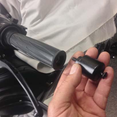
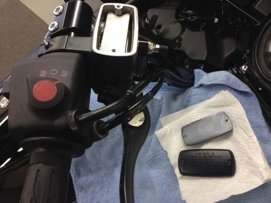
8 on the left control housing (See Photo #31) Loosen the screw that holds the strap against the grommet. Note that the longer screw goes in the forward hole n the left control housing. G. Remove the inner clamp screw and rest housing beside left control housing. NOTE: that the screw is on top on the left housing. 7.) 8.) Remove Left handlebar - F6B STANDARD ONLY (NO HEATED GRIPS!) A. Insert a spade screw driver under the left grip then drip some rubbing alcohol into the grip. (See Photo #33) Carefully push the screw driver deeper and add more alcohol until the screwdriver is 3/4 of the way under the grip. Start twisting and remove the screwdriver. The grip will release and slide off the bar tube. Set aside. B. Remove left handlebar. Goldwing and F6B Deluxe Models with Honda Heated Grips.!!!CAUTION!!! DO NOT, at any time during grip removal, grab the grip and try to twist and pull it off! The design of this grip makes it extremely fragile and it will be permanently damaged and fail to work. Heli Modified is not responsible for failed heated grips.!!!danger!!! Turning on the heated grips requires running the engine. Use proper ventilation to remove carbon dioxide from the workshop or carefully move motorcycle outside for this procedure. A. Turn the heated grips on high and let them heat up for several minutes this will require temporarily plugging in the lower harness of the dash panel. Install grip removal tool as shown in (Photo #34). Slide the horseshoe piece up against the grip followed by the 7/8 shaft collar. Tighten the collar with a 3/16 Allen wrench. B. With the grip hot turn the bolts with a 13MM wrench 1/4 turn at a time alternating from the forward bolt to the rearward bolt. DO NOT turn either bolt more than a 1/4 of a turn before moving to the opposite bolt. The grip will start to move. Turn off the ignition and carefully return motorcycle to workshop. After the bolts are out about 3/4 of an inch from the horse shoe piece, loosen the collar and turn the bolts back in all the way. Slide the collar up against the bolt heads and retighten. Unplug the dash and set aside. If the grip lead looks like it is going to pull tight before the grip slides off the end of the bar tube, enlist an assistant, unbolt the left bar from the triple clamp and have the helper hold the handlebar. Proceed with the horse shoe/collar tool until grip slides off bar tube. DO NOT TWIST OFF OR PULL OFF THE GRIP. Make sure the wire lead does not get stretched as the grip is extracted. Set grip with left control on fairing. C. If you haven t removed left handlebar remove bar now. 9.) Install LST Risers A. Using the 4 stock 10MM bolts, install the left and right risers to the triple clamp. (See Photo #35) DO NOT tighten yet. Use a 14MM socket and an extension. B. Remove riser caps, gently place the cross bar into its bore and re-install caps. Notice there is an (up) arrow on the caps. Lightly tighten the top screws at this time. (See Photo #37) You should be able to read the scripting on the upper caps of the cross bar assembly as seated on the bike. Make sure that the gaps are Page 8 Updated:
9 the same on the right and left sides. (See Photo #38) Move the cross bar assembly left or right to adjust. There should be a small gap between the outsides of the caps and the crossbar. C. Torque the 4 Riser mounting bolts that attach the risers to the forks top triple clamp to 20 ft lbs. (See Photo #36). D. Adjust reach adjustment (closer to rider, farther away) by rotating cross bar. Loosen caps, rotate cross bar forward or back then tighten caps (See Photo #38) starting with the top clamp. Start with the angle shown in the photo. 10.) Install right handlebar tube and controls A. Locate right handlebar tube. Remove inner pinch bolt from the top right pivot. Make sure outer screw is loose. (See Photo #40) Insert the smooth end of the tube into the throttle sleeve. The end with the radial groove goes into the upper pivot bore, line up the locating hole and the control housing dowel pin and engage. Swing clamp over and insert screw. Tighten. (See Photo #41 & 42) Install the two right control housing screws and tighten. B. Engage the right handlebar tube into the upper clamp until it bottoms out, insert pinch bolt and lightly tighten. Use a M6 hex. (See Photo #43) Insert one of the plastic caps provided into the tube end. (See Photo #44) C. Position the front brake master cylinder onto the tube. Place the front brake hydraulic line under the right riser so it aims up the U shape channel. The brake line will fight you a little. Install the right cap, pinch bolts and tighten top screw first. (See Photo #45) Tighten bottom screw, replace plastic cover. D. Loosen the two knurled nuts, reposition the throttle cable elbows down as shown in ( Photo #46) and retighten knurled nuts. E. Place the throttle cables into the groove on the lower right side of the right riser and place one of the 11 cable ties provided around the riser and tighten. (See Photo #47). Cut off excess. F. Turn the fork to the left to gain access, put the front brake hydraulic line, wire loom and heated grip wire inside the channel on the right riser and put the right cover in place, insert screws and tighten. (Photo #48). Make sure the letter R is on the top left corner of the cover. G. On F6B models, re-install the right damper weight. 11.) Install the left handlebar tube and controls A. Remove inner pinch bolt and make sure outer screw is loose. ( Photo #49) B. Insert left handlebar tube in place and re-install inner pinch bolt. Rotate the control housing locating hole so it s facing straight down. Lightly tighten only at this time. (Photo #50) C. Loosen the forward -back wrist angle adjustment pinch bolt and rotate bar forward until it stops. Lightly tighten pinch bolt (See Photo #50) D. Position the left control housing lower half and engage dowel pin into the hole in the handlebar tube, install clamp, screw and tighten. (Photo #51) E. Install upper half into position, insert screws and tighten. The longer screw goes into the forward hole. (Photo #52) F. Put the clutch master cylinder into position. The clutch hydraulic line will resist being twisted at first but it will give. Make sure hydraulic line is under the left riser and inside the U shaped channel. (See Photo #53). Install the cap and screws, tighten the top screw first. Tighten lower screw. Page 9 Updated:
10 12.) Install Left Grip ATTENTION: F6B STANDARD ONLY WITHOUT HEATED GRIPS!! A. Apply rubbing alcohol to the inside of the grip. Twist and slide the grip onto the bar tube and leave 1/8 gap between the grip and the control housing. (See Photo #54) B. Re-install left damper weight and tighten. Twist the end of the grip out until there is about a 3/16 gap between the end of the grip and the damper weight. C. Turn the bars to the right. Use caution to not hit the left rear view mirror with the clutch lever depending on where you adjusted the cross bar assembly. Place the left handlebar wiring cover into position after the hydraulic line and wire loom are position inside the Left riser channel. (See Photo #55) Tighten. D. Place the second 11 cable tie at the bottom of the left riser and around the hydraulic line wire loom. Tighten and trim. (See Photo #56) E. Place plastic cap into the left bar end as per the right side. F. F6B standard motorcycles proceed to step 13. GOLDWING/F6B DELUXE HEATED GRIP INSTALLATION G. Clean the inside of the grip as well as possible removing left over glue pieces. H. Soak the inside of the heated grip with rubbing alcohol as well as the handlebar tube. Looking at the bar tube from the left side of the bike, rotate the grip until the wire lead is roughly at the 7:30 position. (See Photo #57) Make sure inside of the grip is flooded with alcohol, the lead is at the 7:30 turn and using the extractor tool (horse shoe) as shown in (Photo #58) push the grip into place in one quick motion until the tool hits the end of the bar tube. A gap will be present between the grip and the control housing as shown in (Photo #59). This is correct. I. Place the left grip wire lead grommet into its holder. ( Photo #60) J. Turn the handlebars to the right. Don t let the clutch lever hit the mirror. Place the clutch hydraulic line, wire looms and heated grip lead into the risers channel then put its cover in place followed by the screws and tighten.. (Photo #61) The letter L should be in the top right corner of the cover. K. Place an 11 cable tie at the bottom of the left riser and capture the hydraulic line wire loom and left heated grip lead and tighten. Cut off excess. (Photo #62) Place plastic cap into left bar as per the right side. L. Use several 6 cable ties to neaten up the exposed wires on the left handlebar. Cover the taped loom with the smaller covered leads. (Photo #63). Repeat on the right side. 13.) Bleed the clutch and front brake master cylinder. CAUTION: DO NOT bleed the front brake master cylinder from any other location other than the bleeder banjo bolt provided! A. Start with the front brake master cylinder. B. Remove the rubber cap from the bleeder and set aside. C. Carefully remove the reservoir cover and rubber bellows with plastic top. (Photo #63) D. Press the brake lever in only about 1/2 inch and then release quickly. Do this several dozen times and you will notice small bubble starting to appear. This is recharging the cylinder. After the bubbles disappear, open the bleeder while holding a paper towel over it and depress the brake lever half way and close the bleeder before releasing the lever. Use an 8MM wrench. After a couple of times the brake should recharge, release what little air is in the system and get hard. Sometimes it takes 6 or more bleedings. Add DOT 4 if the level is below the top of the sight window and replace the cap and its components. Tighten Page 10 Updated:
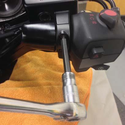
11 and wipe around the cover. Replace rubber cover on the bleeder. E. Repeat on the left side clutch master cylinder. 14.) Adjusting the LST, Torque Values, index marks and stationary indicators to mirror left and right sides. We recommend adjusting the bars to suit your initial desire before installing the instruments and the dash panel. We have found through experience that our first impression is usually right. Depending on where the bars are adjusted, you may need more slack or have too much slack and need to re-adjust cables, hydraulics and looms. A. Forward and back wrist angle adjustments is enabled by loosening the upper pivot pinch bolts. Adjust to desired angle and torque the pinch bolt to 14 ft. lbs. (Photo #66) Use a 6mm hex drive. Mirror the opposite bar adjustment by counting the dots on the cover using the slot as the indicator and matching it up. Torque to 14 ft. lbs. (See Photo #67) B. Up and down wrist angle adjustment. Loosen the pinch bolt (Use an 8MM hex drive) and rotate grip up or down. When desired angle is achieved, torque the pinch bolt to 22 ft. lbs. Mirror the opposite up and down wrist angle adjustment by counting the index marks (dots) and matching them. Remember to count from the same side. (See Photo #69) C. The entire cross bar assembly can be rotated forward and back by loosening the 4 cap screws. Rotate the assembly forward or back for the desired height and reach combination. After adjustment, torque the 4 cap screws to 14 ft. lbs. starting with the top 2 first. (Photo #70) D. Adjust clutch and brake lever height by loosening the two top screws, adjust levers up or down then Torque the two screws to 12 ft lbs. (See Photo #71) Install 4 of the black plastic caps on the 4 screws that clamp the handlebar tubes. (Photo #71) Install the remaining 4 plastic caps on the corss bar clamp screws. 15.) Re-install Instruments and dash in the reverse order of disassembly. A. Install plastic cover by turning bars left then right to access screws. (See Photo #74) B. Install instrument cluster by plugging in the connectors (3 on Goldwing, 2 on F6B) Make sure connectors are pushed in until you hear it click. Note that the rubber bushing (Photo #75) must slide under and up into the fork mount on the fairing frame. (Photo #76) Make sure the two tweeter connectors and rubber boots stay out by the speakers and not behind the instruments. Install the two bolts with large washers on the top 2 holes. Install and tighten. Install the two bottom bolts and tighten. Use an 8MM socket. (See Photo #77) C. Place a shop rag just behind the ignition switch, set the dash in front of the crossbar, plug the connector in and slide it back onto its tang in front of the ignition. Refer to Photo #78 & #79 for clarity. Plug in the two tweeter connectors and rubber boots. Use caution to not damage main speakers. (Photo #78) Slide the dash slightly under the cross bar. (Photo #79) until the upper edge clears the upper fairing and slowly engage the mounts by pushing around the perimeter of the dash panel including around the ignition switch. (Photo #80). On 2012 to 2014 models make sure that your bar adjustments don t interfere with the glove box opening. (Photo #81) D. On GL1800s, install the two remaining 7/8 black plugs in the outside opening of the handlebar tubes where the damper weights used to be. Fully insert. Reference Photo #40. Page 11 Updated:
12 !! CAUTION!! BARS MUST BE TORQUED TO SPECIFIED VALUES. THEY MUST NOT BE OVERTORQUED. OVERTIGHTENED HARDWARE CAN LOSE INTEGRITY. For questions regarding installation please call HELI MODIFIED, INC ASSUMES NO LIABILITY FOR ANY INJURY OR LOSS OF PROPERTY WHICH MAY RESULT FROM IMPROPER INSTALLATION OR USE OF ANY HELIBARS. Page 12 Updated:


13 Photo # 1 Photo # 2 Photo # 3 Photo # 4 Page 13 Updated:


14 Photo # 5 Photo # 6 Photo # 7 Photo # 8 Page 14 Updated: 3-27/2015


15 Photo # 9 Photo # 10 Photo # 11 Photo # 12 Page 15 Updated:


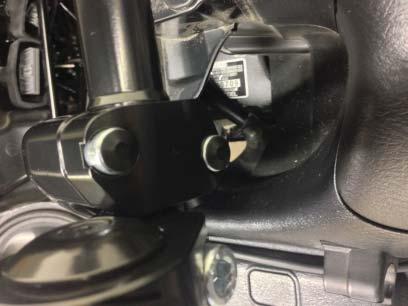
16 F6B Bagger Photo # 13 Goldwing Photo # 14 Photo # 15 Photo # 16 Page 16 Updated: 3-27/2015


17 Photo # 17 Photo # 18 Photo # 19 Photo # 20 Page 17 Updated:


18 Photo # 21 Photo # 23 Photo # 22 Photo # 24 Page 18 Updated: 3-27/2015


19 Photo # 25 Photo # 26 Photo # 27 Photo # 28 Page 19 Updated:


20 Photo # 29 Photo # 31 Photo # 30 Photo # 32 Page 20 Updated: 3-27/2015


21 Photo # 33 Photo # 34B Photo # 34A Photo # 35 Page 21 Updated:


22 Photo # 36 Photo # 37 Photo # 38 Photo # 39 Page 22 Updated: 3-27/2015


23 Photo # 40 Photo # 42 Photo # 41 Photo # 43 Page 23 Updated:


24 Photo # 44 Photo # 46 Photo # 45 Photo # 47 Page 24 Updated: 3-27/2015


25 Photo # 48 Photo # 50 Photo # 49 Photo # 51 Page 25 Updated:


26 Photo # 52 Photo # 53 Photo # 54 Photo # 55 Page 26 Updated: 3-27/2015


27 CLOCK TO 7:30 Photo # 56 Photo # 57 Photo # 58 Photo # 59 Page 27 Updated:


28 Photo # 60 Photo # 61 Photo # 62 Photo # 63 Page 28 Updated: 3-27/2015


29 Photo # 64 Photo # 65 Photo # 66 Photo # 67 Page 29 Updated:


30 Photo # 68 Photo # 69 Photo # 70 Photo # 71 Page 30 Updated: 3-27/2015


31 Photo # 72 Photo # 73 Photo # 74 Photo # 75 Page 31 Updated:


32 Photo # 76 Photo # 77 Photo # 78 Photo # 79 Page 32 Updated: 3-27/2015

33 Photo # 80 Photo # 81 Page 33 Updated:
34 IMPORTANT INFORMATION ABOUT POWDER COATED HELIBARS HeliBars are finished with a polyester powder coating. The polyester is recommended for outdoor use because of it s excellent UV resistant quality; if we were to use an epoxy it would tend to fade and chalk pretty quickly when exposed to sunlight and UV rays. Care must be taken during installation because the finish can be scratched by the sharp surfaces of the controls and master cylinder clamps. When mounting the master cylinders to bars, do not let them move around the bars with the caps loose. Mount them in the proper position and hand tighten the screws until final adjustments are made; in this way you will lessen the possibility of scratching. NOTE: Powder coat finish is not indestructible, there are chemicals which may react negatively when applied to finish. Brake fluid may cause deterioration of the finish. We do not recommend the use of acetone or similar chemicals for cleaning purposes. We would recommend the use of an over-the-counter adhesive remover (such as Goo Gone) for the removal of any extraneous material. Please read labels directions for any cleaning/polishing product before use. If you have any questions regarding the use of any over-counter-products with the Heli- Bars, please call us before applying them to the powder coated finish. If care is taken during installation, your HeliBars will continue to look as good as when they were new. They will look great for years to come with a bit of wax and careful cleaning. Thank you for your purchase, ride safe and enjoy! Sincerely, Harry Eddy, President
INSTALLATION INSTRUCTIONS
 INSTALLATION INSTRUCTIONS 2013-2014 Honda CBR500R/RA Tour Performance Handlebar Risers P/N: HR01087 IMPORTANT: PLEASE GIVE CUSTOMER ENCLOSED INFORMATION! Thank you for your purchase of our HeliBars. They
INSTALLATION INSTRUCTIONS
 INSTALLATION INSTRUCTIONS HeliBars Tour Performance Adjustable Handlebar Bridge 2006-2013 Yamaha FJR1300 US & European P/N: HR09079 IMPORTANT: PLEASE GIVE CUSTOMER ENCLOSED INFORMATION! Thank you for your
INSTALLATION INSTRUCTIONS
 INSTALLATION INSTRUCTIONS 2004-2008 Ducati ST3/ST4 HeliBars Replacement Handlebar Risers P/N: HB2405 IMPORTANT: PLEASE GIVE CUSTOMER ENCLOSED INFORMATION! Thank you for your purchase of our HeliBars. They
INSTALLATION INSTRUCTIONS
 INSTALLATION INSTRUCTIONS Horizon ST Patented Multi Axis Adjustable Handlebar System for 2012-2015 BMW K1600GTL P/N: HST05078 IMPORTANT: PLEASE GIVE CUSTOMER ENCLOSED INFORMATION! Patent No: US 8,230,758
INSTALLATION INSTRUCTIONS
 INSTALLATION INSTRUCTIONS HeliBars Tour Performance Handlebar Riser 2014+ Yamaha Super Tenere P/N: HR09109 IMPORTANT: PLEASE GIVE CUSTOMER ENCLOSED INFORMATION! Thank you for your purchase of our HeliBars.
INSTALLATION INSTRUCTIONS
 INSTALLATION INSTRUCTIONS 2008-2013 Suzuki GSX1300R Hayabusa TracStar Replacment Handlebars P/N: TS03000 IMPORTANT: PLEASE GIVE CUSTOMER ENCLOSED INFORMATION! Thank you for your purchase of our HeliBars.
INSTALLATION INSTRUCTIONS
 INSTALLATION INSTRUCTIONS BMW S1000RR 2015+ TracStar Replacement Handlebars P/N: TS05099 IMPORTANT: PLEASE GIVE CUSTOMER ENCLOSED INFORMATION! Thank you for your purchase of our HeliBars. They are designed
INSTALLATION INSTRUCTIONS HONDA CBR250R P/N: HB01075
 INSTALLATION INSTRUCTIONS HONDA CBR250R P/N: HB01075 IMPORTANT: PLEASE GIVE CUSTOMER ENCLOSED INFORMATION! Thank you for your purchase of our HeliBars. They are designed to increase your long distance
INSTALLATION INSTRUCTIONS
 INSTALLATION INSTRUCTIONS 2006-2008 BMW K1200R TracStar Handlebars P/N: TS05028 IMPORTANT: PLEASE GIVE CUSTOMER ENCLOSED INFORMATION! Thank you for your purchase of our HeliBars. They are designed to increase
INSTALLATION INSTRUCTIONS
 INSTALLATION INSTRUCTIONS BMW K1600GT/GTL 2011+ HeliBars Handlebar Relocation Adapters Part # HR05108 IMPORTANT: PLEASE GIVE CUSTOMER ENCLOSED INFORMATION! Thank you for your purchase of our HeliBars.
INSTALLATION INSTRUCTIONS
 INSTALLATION INSTRUCTIONS 2005-2008 BMW K1200S TracStar Replacment Handlebars P/N: TS05027 IMPORTANT: PLEASE GIVE CUSTOMER ENCLOSED INFORMATION! Thank you for your purchase of our HeliBars. They are designed
INSTALLATION INSTRUCTIONS
 INSTALLATION INSTRUCTIONS 2017+ BMW R9T Racer HeliBars Replacement Triple Clamp w/built in Risers Part # HRT05126 IMPORTANT: PLEASE GIVE CUSTOMER ENCLOSED INFORMATION! Thank you for your purchase of our
INSTALLATION INSTRUCTIONS. KAWASAKI Concours Handlebar Risers for ABS & Non-ABS Part # HR04042 & HR04042-NABS
 INSTALLATION INSTRUCTIONS KAWASAKI Concours14 2008-2015 Handlebar Risers for ABS & Non-ABS Part # HR04042 & HR04042-NABS IMPORTANT: PLEASE GIVE CUSTOMER ENCLOSED INFORMATION! Thank you for your purchase
INSTALLATION INSTRUCTIONS
 INSTALLATION INSTRUCTIONS 1998-2008 R1 & 2008-2013 R6 TracStar Replacment Handlebars P/N: TS09073 IMPORTANT: PLEASE GIVE CUSTOMER ENCLOSED INFORMATION! Thank you for your purchase of our HeliBars. They
INSTALLATION INSTRUCTIONS
 INSTALLATION INSTRUCTIONS 2006-2010 Kawasaki ZX10R TracStar Replacment Handlebars P/N: TS04072-KA 2011-2012 Kawasaki ZX10R TracStar Replacment Handlebars P/N: TS04072-KB IMPORTANT: PLEASE GIVE CUSTOMER
INSTALLATION INSTRUCTIONS
 INSTALLATION INSTRUCTIONS Ducati 749/999 TracStar TM HeliBars Replacement Handlebars P/N: TS07059 IMPORTANT: PLEASE GIVE CUSTOMER ENCLOSED INFORMATION! Thank you for your purchase of our HeliBars. They
INSTALLATION INSTRUCTIONS Horizon XP Performance Handlebar
 INSTALLATION INSTRUCTIONS Horizon XP Performance Handlebar HZ10090XP, HZ10090XP-BA (1 Mount) Gen 1 HZ10093XP, HZ10093XP-BA (1 1/4 Mount) Gen 1 HZ10096XP, HZ10096XP-BA ( 1 1/4 Mount) Gen 2 HZ10097XP, HZ10097XP-BA
INSTALLATION INSTRUCTIONS Horizon CCR HZ13054
 INSTALLATION INSTRUCTIONS Horizon CCR HZ13054 IMPORTANT: PLEASE GIVE CUSTOMER ENCLOSED INFORMATION! Thank you for your purchase of our HeliBars. They are designed to increase your long distance comfort
2010 BMW S1000RR TracStar HeliBars TS mm taller (1.7 ) ~ 20mm Rear Offset (.8 ) ~ Stock Width (25 ¼ )
 ~ 20mm Rear Offset (.8 ) ~ Stock Width (25 ¼ )") WARNING: IMPROPER INSTALLATION COULD RESULT IN SERIOUS INJURY OR DEATH. HAVE A QUALIFIED MECHANIC INSTALL YOUR HELIBARS. Right Side To protect your motorcycle during installation place clean shop rags
WARNING: IMPROPER INSTALLATION COULD RESULT IN SERIOUS INJURY OR DEATH. HAVE A QUALIFIED MECHANIC INSTALL YOUR HELIBARS. Right Side To protect your motorcycle during installation place clean shop rags
INSTALLATION INSTRUCTIONS FOR THE MOTOR TRIKE CROSS COUNTRY / CROSS ROADS / HARD BALL RAKE KIT
 INSTALLATION INSTRUCTIONS FOR THE MOTOR TRIKE CROSS COUNTRY / CROSS ROADS / HARD BALL RAKE KIT Thank you for choosing the Motor Trike Cross Country / Cross Roads / Hard Ball rake kit. We ask that you read
Be sure to read and go over all pages before you start your installation
 Yamaha Gen-2 V-MaxV Holeshot Superbike Bars Installation Guide Pre-Installation Note Be sure to read and go over all pages before you start your installation Preparation for Installation A) It is recommended
w w w. h d o n l i n e s h o p. d e CRUISE CONTROL KIT GENERAL INSTALLATION -J04064 REV Kit Number Models Additional Parts Required
 -J006 REV. 006-08- CRUISE CONTROL KIT GENERAL Kit Number 7796-07 Models For the most up-to-date model fitment information, please see the product label or www.harley-davidson.com. Additional Parts Required.
Installation Manual TWM Performance Short Shifter Cobalt SS/SC, SS/TC, HHR SS, Ion Redline and Saab 9-3
 Page 1 Installation Manual TWM Performance Short Shifter Cobalt SS/SC, SS/TC, HHR SS, Ion Redline and Saab 9-3 Please Note: It is preferable to park on a flat surface, as you will have to engage and disengage
w w w. h d o n l i n e s h o p. d e STREET SLAMMER HANDLEBAR KIT GENERAL INSTALLATION -J03363 REV Kit Number Models Kit Contents
 -J06 REV. 006-06- GENERAL Kit Number 69-0 Models STREET SLAMMER HANDLEBAR KIT Ask a Harley-Davidson dealer or refer to the latest Harley- Davidson Genuine Motor Accessories and Genuine Motor Parts catalog
Multistrada (MTS) Tank Installation Notes. Tools Required. Phase 1: Remove Fairings. Phase 2: Remove Fuel Tank
 Tank Installation Notes. Tools Required. Phase 1: Remove Fairings. Phase 2: Remove Fuel Tank") The California Cycleworks MTS tank provides an aftermarket alternative to the OEM nylon fuel tanks as used on aircooled Desmodue Ducati Multistrada 1100, 1000, and 620 models. This fuel tank is NOT for
The California Cycleworks MTS tank provides an aftermarket alternative to the OEM nylon fuel tanks as used on aircooled Desmodue Ducati Multistrada 1100, 1000, and 620 models. This fuel tank is NOT for
Slave Cylinder Weep Hole Drilling Procedure
 Slave Cylinder Weep Hole Drilling Procedure Tools Required: T20 Torx Driver T25 Torx Driver T25 Torx Bit with ¼ Ratchet Wrench 4mm Hex Key (Allen wrench) 5mm Hex Key 6mm Hex Key 8mm Hex Key 12mm Hex Key
SADDLEBAG AUDIO WIRE HARNESS KIT P/N
 SADDLEBAG AUDIO WIRE HARNESS KIT P/N 2880986 APPLICATION ALL INDIAN MOTORCYCLES WITH BOTH TRUNK AND SADDLEBAG AUDIO INSTALLED BEFORE YOU BEGIN Read these instructions and check to be sure all parts and
Assembly Instructions
 Assembly Instructions Part Number Description Model Approx. Assembly Time 99994-0903 Windshield Wiper Kit Mule SX 1 Hour WARNING Improper installation of this accessory could result in an accident causing
Installation Manual TWM Performance Short Shift Kit Stage 1 and Stage 2 MazdaSpeed 6
 Page 1 Installation Manual TWM Performance Short Shift Kit Stage 1 and Stage 2 MazdaSpeed 6 Please Note: It is preferable to park on a flat surface, as you will have to engage and disengage the hand brake
INSTALLATION INSTRUCTIONS
 INSTALLATION INSTRUCTIONS Accessory Application Publications No. MII 11775 AUDIO ATTACHMENT KIT P/N 08B08-MEA-100 VTX1300S/R Issue Date October 2006 Honda Dealer: Please give a copy of these instructions
w w w. h d o n l i n e s h o p. d e ROAD KING FAT HANDLEBAR KIT GENERAL PREPARATION - ALL MODELS -J02375 REV Kit Number Models ABS Models
 -J02375 REV. 2008--9 GENERAL Kit Number 56675-05 Models For model fitment information, see the P&A Retail Catalog or the Parts and Accessories section of www.harley-davidson.com (English only). ABS Models
HID INSTALLATION ON RST1000 Futura
 HID INSTALLATION ON RST1000 Futura Disclaimer: This is a full description of what I have done to my motorcycle. I am in no way suggesting you do as I have done by following these instructions. I have not
Installation Manual TWM Performance Short Shifter Subaru STi 2008+
 - 1 - Installation Manual TWM Performance Short Shifter Subaru STi 2008+ Please Note: It is preferable to park on a flat surface, as you will have to engage and disengage the hand brake and shift from
Superbike Kit
 Superbike Kit www.spieglerusa.com sales@spieglerusa.com Mounting Instructions & Safety Instructions for Honda CBR 1000 RR ABS model year 2017 - Attention Important Safety Instructions: Thank you for purchasing
w w w. h d o n l i n e s h o p. d e CHROME SWITCH HOUSING KIT GENERAL HANDLEBAR SWITCH REMOVAL/INSTALLATION FXDWGI AND FXDBI MODEL TURN SIGNAL REMOVAL
 -J00 REV. 00-07-9 GENERAL Kit Number 70-9B, 70-9B, 708-9C Models For the most up-to-date model fitment information, please see the product label or www.harley-davidson.com. See Table for items contained
INSTALLATION. Note: Not all parts will be used in the installation of this product. -cont.-
 5005 Fits: 06-up FLHX, 04-up Screamin Eagle Ultra Classic Electra Glide & Screamin Eagle Electra Glide Classic, '97-up FLHT, FLHTC, FLHTCU, FLHR PartS Included 1 Right Driving Light Assembly 1 Left Driving
AmTryke Adult Recumbent Model JT2000 #50-FC-2000
 AmTryke Adult Recumbent Model JT2000 #50-FC-2000 TOOLS Needed for Assembly 5 mm Allen Wrench 8 mm Socket or Wrench 10 mm Socket or Wrench 14 mm Socket or Wrench 15 mm Socket or Wrench 22 mm Socket or Adjustable
P/N Instr Rev Page 1 of 11
 BRAKE AND CLUTCH KIT P/N 2883864 IMPORTANT Due to the technical nature of this kit, Indian Motorcycle insists this installation be performed by a certified Indian Motorcycle Technician. APPLICATION Verify
BrakeAway Products Inc. wishes you many years of cramp free cruising, ENJOY and ride SAFELY!!!
 Congratulations on the purchase of your new BrakeAway Motorcycle Cruise Control. At BrakeAway Products, we are committed to your complete satisfaction. With proper installation, use, and periodic maintenance,
Replacing a Brake Line by UCLA-Vstar, April 2007
 Replacing a Brake Line by UCLA-Vstar, April 2007 Replacing a brake line may seem intimidating if you ve never bled brakes before, and especially if you cannot find a stepby-step how-to. Here s a crude
Assembly Instructions
 www.rockymounts.com TandemMount R4 Installation Manual Guidelines/Restrictions: - This carrier is intended for Thule rectangular and Yakima round bars only. - Bicycles must be equipped with quick release
OIL COOLER KIT INSTALLATION INSTRUCTIONS PART NUMBER D E92 335i/xi (N55 engine) with M-Technic bumper and without stock oil cooler
 with M-Technic bumper and without stock oil cooler") OIL COOLER KIT INSTALLATION INSTRUCTIONS PART NUMBER D570-0925 APPLICATION 2011-12 E92 335i/xi (N55 engine) with M-Technic bumper and without stock oil cooler Congratulations for being selective enough
OIL COOLER KIT INSTALLATION INSTRUCTIONS PART NUMBER D570-0925 APPLICATION 2011-12 E92 335i/xi (N55 engine) with M-Technic bumper and without stock oil cooler Congratulations for being selective enough
INSTALLATION INSTRUCTIONS FOR THE MOTOR TRIKE GL1500 RAKE KIT
 INSTALLATION INSTRUCTIONS FOR THE MOTOR TRIKE GL1500 RAKE KIT Thank you for choosing the Motor Trike GL1500 Rake Kit. We ask that you read the directions before you start and follow them very closely.
Remove the 3-11mm nuts holding mirror on. Don t drop the nuts!
 2005-2012 Ford Mustang Puddle Lamp Kit Parts List: Quantity: Tool List: LED Lamps 2 Flat head screwdriver Seals 2 Ratchet & Socket set OR Nuts 2 Adjustable Wrench Wiring harness 1 Drill & 11/16 th bit
R O A D S M I T H TRIKE CONVERSIONS BY THE TRIKE SHOP
 R O A D S M I T H TRIKE CONVERSIONS BY THE TRIKE SHOP Please thoroughly review the instructions before and during installation. Keep in mind that this product was designed to be installed by trained dealer
INSTALLATION INSTRUCTIONS
 THANK YOU FOR CHOOSING KURYAKYN! Protect yourself and others from possible injury and property damage or loss. Pay close attention to all instructions, warnings, cautions, and notices regarding the installation,
Installation Manual TWM Performance Kia Forte Short Shifter
 Installation Manual TWM Performance Kia Forte 2009+ Short Shifter Begin the installation by parking on a flat surface, as you will have to engage and disengage the hand brake and shift from gears to neutral.
AmTryke Adult Recumbent Model HP1000 #50-HC-1000
 AmTryke Adult Recumbent Model HP1000 #50-HC-1000 TOOLS Needed for Assembly 5 mm Allen Wrench 8 mm Socket or Wrench 10 mm Socket or Wrench 14 mm Socket or Wrench 15 mm Socket or Wrench 22 mm Socket or Adjustable
INSTALLATION CONSTELLATION DRIVING LIGHTS 5009
 INSTALLATION CONSTELLATION DRIVING LIGHTS 5009 PARTS INCLUDED 1 Right Driving Light with Turn Signals 1 Left Driving Light with Turn Signals 1 Installation Component Kit Including: 8 Insulated Male Spades
INSTALLATION. DRIVING LIGHTS for FLHT/FLHX/FLHR 5005
 DRIVING LIGHTS for FLHT/FLHX/FLHR 5005 PARTS INCLUDED 1 Right Driving Light Assembly 1 Left Driving Light Assembly 1 Right Driving Light Bracket 1 Left Driving Light Bracket 4 Driving Light Bracket Plugs
I N S TA L L AT I O N
 I N S TA L L AT I O N 5008 fits: H-D: '80-Up Electra glide, tour glide, road king, road glide or street glide PartS Included 1 Right Fork Mount Assembly 1 Left Fork Mount Assembly 2 H3 Driving Light Assemblies
R O A D S M I T H TRIKE CONVERSIONS BY THE TRIKE SHOP
 R O A D S M I T H TRIKE CONVERSIONS BY THE TRIKE SHOP Please thoroughly review the instructions before and during installation. Keep in mind that this product was designed to be installed by trained dealer
Signal Mirror Installation Instructions
 Signal Mirror Installation Instructions Ford F-250 to F-750 Pick-Up, Super-Duty 1998-2007 Trailer Tow Mirror Ford Excursion XLT/Limited 2000-2002 Trailer Tow Mirror Ford Excursion (all models) 2003-2005
This chapter covers the location and servicing of the front brake components for the KYMCO MXU 700i and MXU 500i models.
 KYMCO MXU 500i/700i Repair Manual Brake System 9.Brake System This chapter covers the location and servicing of the front brake components for the KYMCO MXU 700i and MXU 500i models. 1.Brake Discs... 9-3
INSTALLATION INSTRUCTIONS
 INSTALLATION INSTRUCTIONS Accessory LED FOGLIGHT ATTACHMENT KIT P/N 08V70-MKC-A00 Application GL1800/B/BD/D/DA Honda Dealer: Please give a copy of these instructions to your customer. Publication No. MII
Cobra & Cobra XL. Power Trak Current GL1800 Goldwing. Installation Instructions. California Sidecar Parts & Technical Support
 Cobra & Cobra XL by 2001 - Current GL1800 Goldwing Power Trak 6 Installation Instructions REVISED 1 2015 California Sidecar Parts & Technical Support 434.263.8866 Warnings and considerations: 1. Disclaimer
INSTALLATION FORK MOUNTED DRIVING LIGHTS 5008
 5008 PARTS INCLUDED 1 Right Fork Mount Assembly 1 Left Fork Mount Assembly 2 H3 Driving Light Assemblies 1 12-Pin Wiring Adapter 1 Hardware Kit for Fork Mount Driving Lights, Including: 6 5/16-18 Nylock
INSTALLATION CLAMP-ON FORK MOUNTED DRIVING LIGHTS 5015
 CLAMP-ON 5015 PARTS INCLUDED 2 Driving Lights 2 Side Mount Clamps-43mm/49mm 1 Hardware Kit Including: 2 49mm Spacers 4 43mm Spacers 2 Pivot Dome Washers 2 3/8-16 Serrated Hex Nut 1 Wiring Kit for Driving
OIL COOLER KIT INSTALLATION INSTRUCTIONS PART NUMBER D
 OIL COOLER KIT INSTALLATION INSTRUCTIONS PART NUMBER D570-0904 APPLICATION: 2011-2012 E90 335i/xi (N55 engine) with BMW standard bumper and with stock oil cooler Congratulations for being selective enough
INSTALLATION CONSTELLATION DRIVING LIGHTS 5009
 INSTALLATION CONSTELLATION DRIVING LIGHTS 5009 PARTS INCLUDED 1 Right Driving Light with Turn Signals 1 Left Driving Light with Turn Signals 1 Installation Component Kit Including: 8 Insulated Male Spades
Accessory Fitting Instructions
 Accessory Fitting Instructions Kit Number Models Affected A9689 Thruxton 00 A96808 Thruxton 00 R Low Handlebar Kit Front Fairing Kit Kit Number Models Affected A97080 Thruxton 00 A97084 Thruxton 00 R Note:
INSTALLATION & OWNER S MANUAL
 Rev. B, p. 1 of 25 INSTALLATION & OWNER S MANUAL POLARIS RANGER RCS (for models XP or HD) (for model years 2009-) cab without doors kit (p/n 1POLRCWD) cab with doors kit (p/n 1POLRC) doors only kit (p/n
INSTALLATION GUIDE. RMS510, 511, 512, 513, 511MC 510-OR, 512-OR Manual Revision:
 REKLUSE MOTOR SPORTS z-start Dual-Actuated Brake Kit INSTALLATION GUIDE RMS510, 511, 512, 513, 511MC 510-OR, 512-OR 196-210 Manual Revision: 051309 2002-2009 Rekluse Motor Sports Rekluse Motor Sports,
Low Range HD 2 Inch Body Lift Kit (Sidekick, GV, Vitara, Tracker, X90) SKU# KSP-BL2
 SKU# KSP-BL2") Low Range HD 2 Inch Body Lift Kit (Sidekick, GV, Vitara, Tracker, X90) SKU# KSP-BL2 Installation Instructions Background: These instructions are designed for installing the 2 body lift. They can also be
Low Range HD 2 Inch Body Lift Kit (Sidekick, GV, Vitara, Tracker, X90) SKU# KSP-BL2 Installation Instructions Background: These instructions are designed for installing the 2 body lift. They can also be
FlexJet - Flex Cable Replacement
 P/N: 109515R0 14140 NE 200th St. Woodinville, WA. 98072 PH: (425) 398-8282 FX: (425) 398-8383 FlexJet - Flex Cable Replacement Notices: Warning! Ensure that all AC power cables are removed from the printer
GP1-R FULL EXHAUST SUZUKI GSX-R600 / GSX-R
 THIS EXHAUST SYSTEM IS DESIGNED FOR USE IN CLOSED COURSE RACING ONLY, AND IS NOT INTENDED FOR PUBLIC HIGHWAY USE. IN THE STATE OF CALIFORNIA, IT IS ILLEGAL TO MODIFY THE EMISSION CONTROL SYSTEM ON ANY
Installation instructions for Alpha Racing Quickshifter/Blipper for a pre-2014 S1000RR
 Skill Level: Intermediate Installation instructions for Alpha Racing Quickshifter/Blipper for a pre-2014 S1000RR Tools Required: Alen keys/socket/drivers Torx keys/sockets/drivers Metric box wrenches and
06-11 Civic Si / EM1 Clutch Master Cylinder
 06-11 Civic Si / EM1 Clutch Master Cylinder Upgrade This guide will show you how to install the EM1 CMC upgrade kit in a 2006-2011 Honda Civic Si. Written By: Hybrid Racing 2017 guides.hybrid-racing.com/
CALIFORNIA TRIMMER MOWER MAINTENANCE MANUAL
 CALIFORNIA TRIMMER MOWER MAINTENANCE MANUAL 2 Table of Contents Section 1: General Information Page Handle Assembly Instructions 4 Maintenance All Models 6 Oil Change Procedures All Models 9 Height Adjustment
w w w. h d o n l i n e s h o p. d e MODULAR DIAMONDBACK BRAKE LINE KITS GENERAL -J04284 REV Kit Number Models Tools and Supplies Required
 -J08 REV. 007-07-6 GENERAL MODULAR DIAMONDBACK BRAKE LINE KITS Table. Upper Brake Line s (Banjo Angle 0 - Straight) 7-07 77-07 79-07 8-07 87-07 9-07 8-07 8 inch 9 inch 0 inch inch inch inch inch 96-07
-Magnet (not completely necessary but can come in handy)
") McLeod High Performance Hydraulic Clutch Line Upgrade (05-14 V8) Included in kit: -New clutch line -2 fittings Required Tools: -Floor jack and jack stands (or a lift) -Flashlight -Angled pick tool -13mm
McLeod High Performance Hydraulic Clutch Line Upgrade (05-14 V8) Included in kit: -New clutch line -2 fittings Required Tools: -Floor jack and jack stands (or a lift) -Flashlight -Angled pick tool -13mm
TOPAZ Service Guide. Full Service
 TOPAZ Service Guide Full Service SERVICE OVERVIEW This manual will guide you step by step performing an air service to your Topaz. Please follow each instruction carefully to achieve the best and safest
SUM Chevy Truck frame mount booster kit
 SUM-760211 1955-1959 Chevy Truck frame mount booster kit Unboxing your kit: 1. Remove new booster, bracket assembly and master cylinder from their boxes and inspect the parts. 2. New boosters come with
INSTALLATION INSTRUCTIONS 97 FORD EXPEDITION
 INSTALLATION INSTRUCTIONS 97 FORD EXPEDITION 1. Read the instructions completely and carefully before you begin. Check the kit for proper contents (refer to the part s list and the picture diagrams). Before
w w w. h d o n l i n e s h o p. d e CHROME 1.25 INCH (31.75 MM) DIAMETER HANDLEBAR KIT GENERAL INSTALLATION -J04405 REV Kit Number Models
 DIAMETER HANDLEBAR KIT GENERAL INSTALLATION -J04405 REV Kit Number Models") -J005 REV. 008-09-0 CHROME.5 INCH (.75 MM) DIAMETER HANDLEBAR KIT GENERAL Kit Number 560-08 Models For model fitment information, see the P&A retail catalog or the Parts and Accessories section of www.harley-davidson.com
-J005 REV. 008-09-0 CHROME.5 INCH (.75 MM) DIAMETER HANDLEBAR KIT GENERAL Kit Number 560-08 Models For model fitment information, see the P&A retail catalog or the Parts and Accessories section of www.harley-davidson.com
RMK HANDLEBAR KIT P/N ; ; APPLICATION BEFORE YOU BEGIN KIT CONTENTS. Verify accessory fitment at Polaris.com.
 RMK HANDLEBAR KIT P/N 2883835; 2883836; 2883837 APPLICATION Verify accessory fitment at Polaris.com. BEFORE YOU BEGIN Read these instructions and check to be sure all parts and tools are accounted for.
INSTRUCTIONS. w w w. h d o n l i n e s h o p. d e SPRINGER AUXILIARY LAMP KIT 1WARNING -J03497 REV General.
 INSTRUCTIONS -J097 REV. 0-0-00 Kit Number 6986-0A General Auxiliary/fog lamps are not included in this kit. The lamps must be purchased separately. HDI (International) motorcycles should only use approved
w w w. h d o n l i n e s h o p. d e ROAD TECH QUEST GLOBAL POSITIONING SYSTEM (GPS) MOUNTING KIT GENERAL INSTALLATION -J03554 REV.
 MOUNTING KIT GENERAL INSTALLATION -J03554 REV.") -J03554 REV. 007-08-0 ROAD TECH QUEST GLOBAL POSITIONING SYSTEM (GPS) MOUNTING KIT GENERAL Kit Number 900-05 Models For model fitment information, please see the P&A Retail Catalog or the Parts and Accessories
-J03554 REV. 007-08-0 ROAD TECH QUEST GLOBAL POSITIONING SYSTEM (GPS) MOUNTING KIT GENERAL Kit Number 900-05 Models For model fitment information, please see the P&A Retail Catalog or the Parts and Accessories
VW/AUDI MK7 VEHICLES
 Installation Manual P/N 1-301-1708-01 (STAGE 2+ FUEL KIT) P/N 1-301-1708-02 (STAGE 3+ FUEL KIT) VW/AUDI MK7 VEHICLES Warning: This installation is not recommended for a novice or the new guy in the shop.
INSTALLATION GUIDE. Doc ID: A Doc Rev:
 REKLUSE MOTOR SPORTS EXP Kit for Harley-Davidson Big Twin Hydraulic-Actuated OVERVIEW INSTALLATION GUIDE Doc ID: 191-6200A Doc Rev: 061215 This kit replaces the OEM clutch pack (friction disks and drive
INSTALLATION INSTRUCTIONS
 INSTALLATION INSTRUCTIONS Accessory Application Publications No. CD CHANGER ATTACHMENT KIT 2005 CIVIC SI AII 27936 Issue Date AUG 2004 PARTS LIST CD Changer Attachment Kit (sold separately): P/N 08B26-S5T-100
DETACHABLE QUARTER FAIRING AND DOCKING HARDWARE KIT
 INSTRUCTIONS -J09 REV. 0--00 Kit Numbers 7070-98 (primed kit) DETACHABLE QUARTER FAIRING AND DOCKING HARDWARE KIT General This kit is for installation on 988 and later XL, FXR and FXD model motorcycles
INSTALLATION PROCESS: FK003D945-7 Complete Front, Rear, and Clutch A.B.S. KIT Harley Davidson FLH Touring Models
 INSTALLATION PROCESS: FK003D945-7 Complete Front, Rear, and Clutch A.B.S. KIT 2014-2017 Harley Davidson FLH Touring Models Parts List: 4 Lines 1 Brake Light Switch Adapter 7 Single banjo bolts 2 Caliper
w w w. h d o n l i n e s h o p. d e CHROME FRONT BRAKE MASTER CYLINDER KIT GENERAL INSTALLATION -J03735 REV Kit Number Models
 -J05 REV. 005-06- GENERAL Kit Number 58-D, 58-D Models CHROME FRONT BRAKE MASTER CYLINDER KIT These Chrome Master Cylinder Kits are designed to replace the original equipment front brake master cylinder
GL1800 TRAILER HITCH - INSTALLATION INSTRUCTIONS #GL
 GL1800 TRAILER HITCH - INSTALLATION INSTRUCTIONS #GL18007-20 Read through these instructions completely before attempting installation, lay out all pieces including the numbered hardware bags to familiarize
Installation Manual TWM Performance Short Shifter 2008 Mitsubishi Lancer
 Page 1 Installation Manual TWM Performance Short Shifter 2008 Mitsubishi Lancer Please Note: It is preferable to park on a flat surface, as you will have to engage and disengage the hand brake and shift
Short Shifter Installation Instructions For Miata, 6-speed Manual Transmission
 Short Shifter Installation Instructions For 2006-15 Miata, 6-speed Manual Transmission PART# 994-060 Required tools: 10mm deep socket Long extension Ratchet Small flathead screwdriver Phillips-head screwdriver
INSTALLATION. Note: Not all of the included parts will be used during this installation. -cont.-
 Driving Lights for Road Glide 5007 Fits: 98-up Road Glide PartS Included 1 Right Light Assembly 1 Left Light Assembly 1 Right Mounting Bracket 1 Left Mounting Bracket 1 Hardware Kit Including: 2 Narrow
INSTALLATION INSTRUCTIONS
 Accessory Application Publication No. INSTALLATION INSTRUCTIONS S ATTACHMENT KIT P/N 08T70-MJW-D90 After 15 CB500X/XA Honda Dealer: Please give a copy of these instructions to your customer. MII 15802
DISC BRAKE/DUAL MASTER CYLINDER CONVERSION. Tools, Equipment and Supplies Needed:
 Please take the time to read the enclosed instructions carefully. If you have any questions, call our Product Assistance personnel for clarification. It is important to note that these instructions contain
INSTALLATION INSTRUCTIONS
 Accessory Application Publication No. INSTALLATION INSTRUCTIONS HEATED GRIPS P/N 08T71-MKK-D00 After 17 CRF1000L/LD Honda Dealer: Please give a copy of these instructions to your customer. MII 16656 Issue
OIL COOLER KIT INSTALLATION INSTRUCTIONS PART NUMBER D E92 335i/xi (N55 engine) with BMW Standard bumper and with stock oil cooler
 with BMW Standard bumper and with stock oil cooler") OIL COOLER KIT INSTALLATION INSTRUCTIONS PART NUMBER D570-0924 APPLICATION: 2011-12 E92 335i/xi (N55 engine) with BMW Standard bumper and with stock oil cooler Congratulations for being selective enough
OIL COOLER KIT INSTALLATION INSTRUCTIONS PART NUMBER D570-0924 APPLICATION: 2011-12 E92 335i/xi (N55 engine) with BMW Standard bumper and with stock oil cooler Congratulations for being selective enough
Ford Mustang V6 OEM-Style Fog Light Kit Parts List: Quantity: Tool List:
 2015-2017 Ford Mustang V6 OEM-Style Fog Light Kit Parts List: Quantity: Tool List: LED Foglights/ Bezels 2 Flat head & Phillips screwdriver (if you ordered part#3600) Ratchet & Socket set OR Wiring harness
INSTALLATION INSTRUCTIONS
 Accessory Application Publication No. INSTALLATION INSTRUCTIONS HEATED GRIP ATTACHMENT P/N 08T70-MJE-D00 CBR650F/FA MII 14960 Issue Date April 2014 PARTS LIST HEATED GRIP Sold separately (1) (2) (4) (2)
HiBoy Maverick/Commander Doors Part # HiBoy4 Maverick/Commander Doors Black
 Racing 3191 N Washington St. Suite 2 Chandler, AZ 85225 1 (800) 708-9803 http://www.racing.com HiBoy Maverick/Commander Doors Part # 07-2001 HiBoy4 Maverick/Commander Doors Black Congratulations on your
R O A D S M I T H TRIKE CONVERSIONS BY THE TRIKE SHOP
 R O A D S M I T H TRIKE CONVERSIONS BY THE TRIKE SHOP Please thoroughly review the instructions before and during installation. Keep in mind that this product was designed to be installed by trained dealer
2. Remove front wheels.
 1 PARTS DIAGRAM 2 Installation Instructions: (PASSENGER SIDE) 1. Place jack under center of RUV front end and lift until front wheels clear the ground. Be careful to support the RUV properly so that it
OIL COOLER KIT INSTALLATION INSTRUCTIONS PART NUMBER D
 OIL COOLER KIT INSTALLATION INSTRUCTIONS PART NUMBER D570-0907 APPLICATION: 2011-12 E90 335i/xi (N55 engine) with BMW M-Technic bumper and without stock oil cooler Congratulations for being selective enough
w w w. h d o n l i n e s h o p. d e HEATED HAND GRIP KITS GENERAL REMOVAL -J02983 REV Kit Number Models Kit numbers Service Parts
 -J098 REV. 007-0-0 GENERAL Kit Number 56047-0B, 5607-0B, 5674-0B, 5696-0B, 565-0B, 5669-0A, 56694-04A, 56750-04A, 5688-0A, 569-05, 5696-05, 56997-07 Models For model fitment information, please see the
INSTALLATION GUIDE. RMS500, RMS501, RMS502, RMS503, RMS506, RMS507, RMS508, RMS509, -OR Manual Revision:
 REKLUSE MOTOR SPORTS z-start Brake Kit INSTALLATION GUIDE RMS500, RMS501, RMS502, RMS503, RMS506, RMS507, RMS508, RMS509, -OR 196-200 Manual Revision: 051309 2009 Rekluse Motor Sports Rekluse Motor Sports,