GL1800 TRAILER HITCH - INSTALLATION INSTRUCTIONS #GL
|
|
|
- Claribel Lang
- 5 years ago
- Views:
Transcription
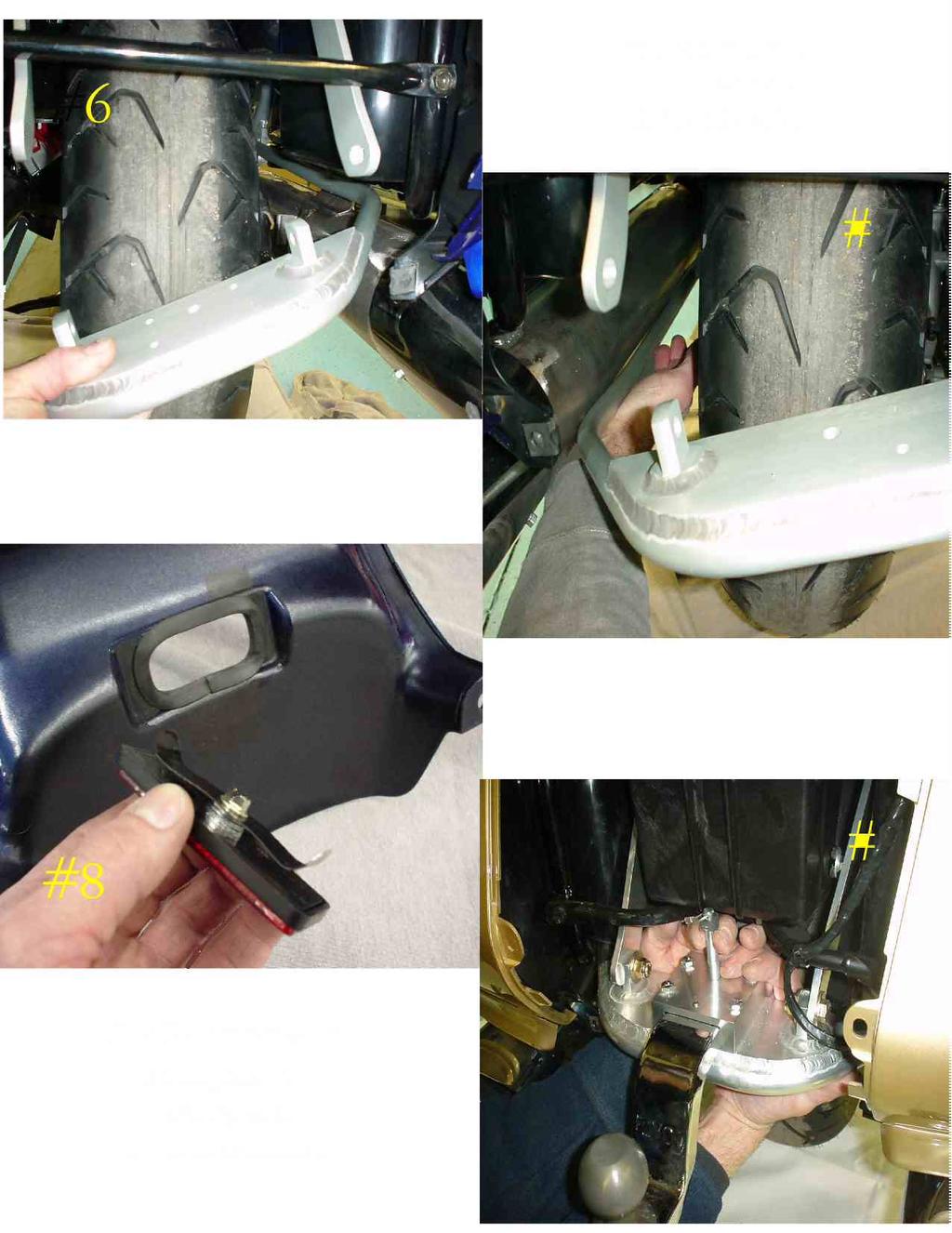
1 GL1800 TRAILER HITCH - INSTALLATION INSTRUCTIONS #GL Read through these instructions completely before attempting installation, lay out all pieces including the numbered hardware bags to familiarize yourself with all parts-see photo #1. 1. Place the motorcycle on its centerstand; remove the seat, side covers, and gray plastic frame covers surrounding the rear crash bars and passenger floorboards. Remove the rear fender. On models: there are five screws - one is located behind the license plate. On models: there are four screwsnone behind the license plate. 2. Remove the rear crash bars and lower sub-frame (black) mounting bolts. (See photo #2) Next drill out the threads of the sub-frame mounting bolt hole on the right side ONLY using a 5/16 drill. (This is required due to the limited space between the hitch and rear suspension. The new bolt supplied for this hole is longer and will now screw into the threaded hole on the right side of the hitches frame.) 3. Install the frame reinforcement plates. (See photo #2 (right side)). Note: left = G and right = F Start the M8 x 25mm bolts from bag #1; do not tighten. Install the longer of the two remaining bolts M8 X 50mm in the remaining hole on the left hand side; tighten securely. (26-28 ft lbs.) 4. Remove the upper sub-frame (Black) from mainframe mounting bolts at the rear of the seat. (See photo #3) Install the struts, (Note: left = B ((has double offset bends)) and right = C ) by sliding them up from below between the inner fender and saddlebag starting in a nearly vertical position. (See photo #4) It will take a little twisting to get them into position. Take caution not to pinch or cut any of the wire looms near the mounting holes (See photo #5). It will help if you unplug the small wires and re-route them over the top of the frame. On models only; on the left side of the main wire harness there is a large lump; this is an unused plug. Using a knife carefully cut the tape off and uncover the plug. This will give you some room to move the plug and harness around the strut as you install it. Once in place install the 5/16 X 2 ¼ long bolts, washers, and nuts from bag #2 thru the frame, sub-frame, and struts. Snug only do not tighten. Angle the bottom of the struts to the rear as far as possible. On 2006 and newer models there is a heat shield on the right muffler to help keep the rear brake caliper cooler. Remove the 10mm Acorn nut at the top of the heat shield and replace it with the regular 10mm nut supplied. 5. Install the hitch main frame ( A ) by placing it around the rear wheel and below the mufflers. Angle the right side up and over the right muffler. (See photo #6) Push the left side up over the left muffler. Note: this will require some force and slight flexing of mufflers. (See photo #7). Slide the left side of the hitch over the end of the M8 x 50mm bolt installed earlier in step #3. Locate the remaining M8 x 40mm bolt from bag #1. Apply a small amount of Loc-Tite or similar thread locking compound (not included) to the bolt. Align the right side of the hitch and install the bolt. Tighten securely. (26-28 ft lbs.) Install the 8mm nut from bag #1 on the left side and tighten to (20-22 ft lbs.) while holding the bolt head with a wrench. Re-install the rear crash bars and plastic frame covers. 6. Align lower strut holes with the mating holes in the main hitch. Note: the struts mount outward of the tabs on the main frame. Install the 3/8 x1 ¼ long bolts, washers, and nuts from bag #2. Do not tighten; snug only. 7. Install the receiver block ( E ) onto the main hitch frame using the 1/4 X 1 ¾ long bolts, washers, and nuts from bag #3. Do not tighten; snug only. Install the tongue ( D ) and hitch pin into the receiver, now tighten the bolts securely. (12-14 ft lbs.) Next remove the hitch pin and adjust the setscrews on the top and side of the receiver block so that the tongue slides in and out but does not rattle. These can be adjusted periodically as needed.
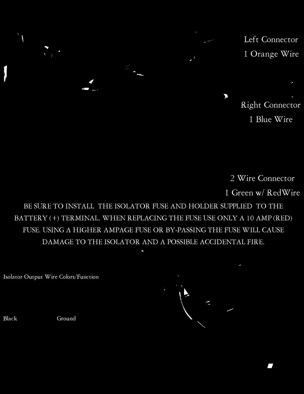
2 8. Lay the rear fender painted side down on a soft cloth or towel. Remove the reflector. Cut out the template from the instruction sheet. Lay the template over the reflector hole in the fender; align it with the reflector outline on the fender. Scribe or mark a line around the template. Next cut out to the line. This is best done using a small grinder or Dremel type moto-tool with a 1/8-router bit. Do not worry if you go slightly over the line or your lines are not perfectly straight. The trim will cover slight imperfections. Fit the trim into the opening with the seam centered at the bottom. Cut to length using a razor blade or sharp knife. (See photo #8) Carefully use a small amount of super glue under the edge of the trim both inside and out as well as the seam, being careful not to get it on the paint! Install the remaining four 1/4 washers from bag #3 and the clip onto the reflector. (See photo #8) Align the clip and tighten using the original nut. Lubricating the trim with Armor All or WD-40 will allow the reflector to slide in and out easily. 9. Installing tongue and hitch pin: Before mounting the rear fender practice installing the hitch pin into the receiver and tongue as described by the following procedure; refer to photo #9, this will help you to better visualize how to install the tongue and pin when the fender is installed. Place one hand on the backside of the receiver slot, with the tongue in the other hand push the tongue into the receiver until it is flush with the back of the slot. Insert the supplied pin thru the receiver and tongue from the bottom up to align the holes in the receiver with the hole in the tongue, remove the pin. Now install the pin from the top down by holding the pin in one hand with two fingers and guiding it to the hole with two fingers from your other hand as shown in photo #9. Install the bowtie clip into the hole at the bottom of the pin being sure the clip is fully engaged to its locking position. 10. Reposition the rear fender and snap it into place temporarily. Install the tongue thru the hole. Adjust the hitch receiver height to center the tongue in the opening. Carefully remove the tongue and rear fender, and tighten the lower strut bolts securely. (35-38 ft lbs.) Next tighten the upper strut to frame mounting bolts securely. (25-28 ft lbs.). Remove the fender and proceed to the next step. 11. Refer to the supplied wiring diagram for installation of the plug in sub harness, electronic trailer isolator unit and 5 to 4 wire convertor (if needed) all sold separately. Wiring components required for plug in wiring to trailer Rivco pt# GL Sub harness Rivco pt# GL17007-IU Wiring Isolator Rivco pt# EC to 4 wire system convertor (if trailer uses a 4 wire system) NOTE: Unless you have all LED lighting on your trailer it is STRONGLY recommended to use an electronic trailer wiring isolator (not supplied) RIVCO pt# GL18007-IU. It is designed to draw the additional 7-10 amps of power needed for the trailer s lighting directly from the battery, not thru the brake, tail or turn signal circuits of the motorcycle. The isolator senses when power is applied to these circuits and activates the trailer lighting accordingly. It is a solid-state electronic device that will protect the motorcycle s advanced electrical systems. It will supply up to 10 amps per circuit to the trailer. NOTE! The isolator is designed for trailers with a five-wire system, which, like the motorcycle will have separate turn signal bulbs. If the trailer you will be towing has a four-wire system (combined brake and stop lights) you will also need to add a five-to-four wire convertor in line before the isolator (not supplied) RIVCO pt# EC They can also be purchased at most auto parts stores but will not have our plug in connector and will need to be spliced in line. You will also need our plug in wiring sub harness Rivco pt# GL to connect the motorcycles wiring to the isolator and or the 5 to 4 wire convertor.
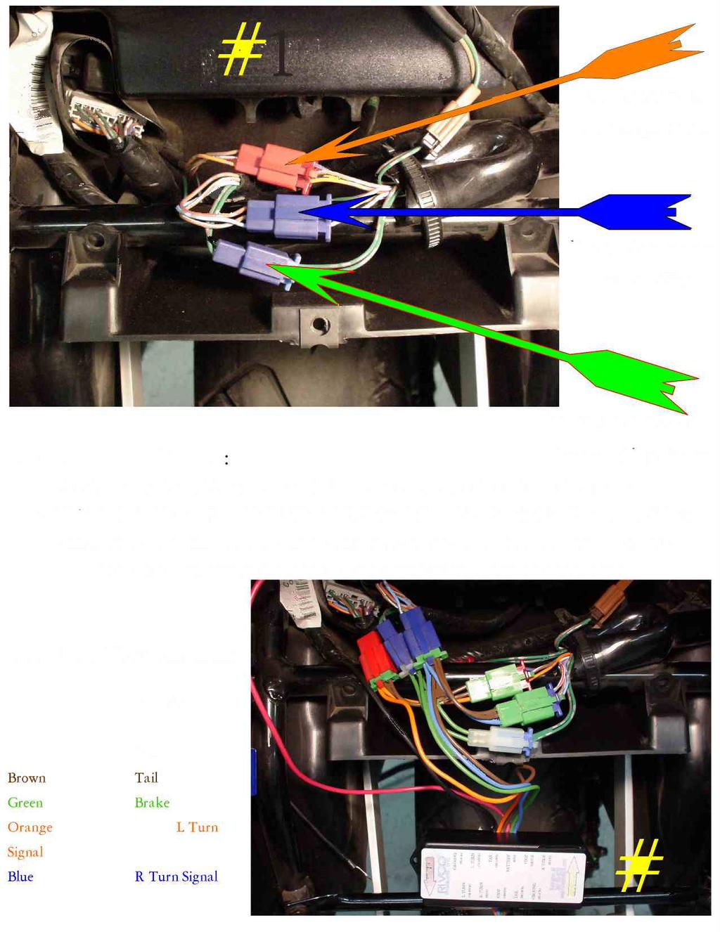
3 12. Facing the rear wheel where the fender was removed earlier above the hitch there is a ledge or shelf, on this shelf there is a bundle of wires cable tied to the frame. Remove the cable tie securing the bundle; slide back the rubber boot exposing the connectors. 13. Remove the sub harness from its package and familiarize yourself with its connectors and wire colors and the supplied wiring diagram. Locate the red three pin connector with an orange wire on the bike. Unplug this connector and plug in the connector from the sub harness with the brown wire in line. Next locate the blue three pin connector on the bike. Unplug this connector and plug in the connector from the sub harness with the Green and Yellow wires in line. Locate either of the remaining two pin connectors on the bike with a Green and Green with a Red stripe. Unplug one of these connectors and plug in the remaining two pin connector from the sub harness with the Blue wire. 14. Plug the remaining connector from the sub harness into the mating connector on the five to four convertor (if you are using one, Rivco pt# EC07664) then the connector on the isolator (Rivco pt# GL18007-IU described above) or from the sub harness to the isolator directly if not using a 5 to 4 wire convertor. Place the connectors back into the rubber boot and cable-tie it back in place. Place the isolator (and 5 to 4 wire convertor if used) on the ledge with the other connector and secure in place using the double-sided tape provided or cable ties. 15. On models mount the isolator to the floor of this wiring compartment using the adhesive strips on the bottom of the isolator. On 2006 & newer models the stereo amplifier is mounted in a large plastic box directly below the wire connectors. The isolator can also be mounted inside this box as follows. Unhook & lift the rubber cover. Remove the two 8mm bolts from the rear of the box. Lower the box and mount the isolator inside the amplifier box. (Clean the surface with rubbing alcohol to ensure good adhesion). Replace the bolts and rubber cover. 16. Attach the black ground wire with the ring terminal to the 10mm bolt on the left end of the horizontal cross brace tube between the saddlebags. Be sure to place the terminal under the head of the bolt and not between the brace and sub-frame to ensure a good ground. 17. Route the trailer wires down the left sub-frame tube to the bottom of the receiver or fender, secure with cable ties provided. The trailer connector is not provided as there are many different couplers used. Follow the color code/function label on the isolator to make the proper connections to your particular trailer connector. 18. Route the Red wire from the isolator forward to the battery positive (+) terminal. Using the fuse holder provided cut & strip the Red wire to the desired length. Crimp it to the fuse holder and attach it to the battery positive (+) terminal. 19. Using a test light or meter turn on the ignition and test the tail, brake and turn signal functions at the appropriate colored wires at the end of the isolator harness where you will be attaching your trailer plug. Connect your trailer plug to the harness to obtain the correct light functions. We recommend the use of a loose plug vs. a mounted receptacle leaving enough wire for the plug to be outside of the fender when in use. When not plugged into the trailer the connector can be stored securely by routing it thru the hitch pin clip. 20. Replace the side covers, rear fender, seat (be sure to connect heated seat cord if so equipped) and any other parts removed earlier Safety chain hook holes are provided on the vertical flange of the main hitch frame just below the receiver block.
4 TRAILER TOWING GUIDELINES AND SAFETY Remember: this is only a guide and should be supplemented with your own common sense for safe operation. WARNING: TOWING A TRAILER BEHIND A MOTORCYCLE IS DONE SO AT YOUR OWN RISK AND INCREASES THE LIKELIHOOD OF INJURY OR DEATH TO BOTH OPERATOR AND PASSENGER DUE TO INCREASED RISK AND EXPOSURE. FAILURE TO OBSERVE THE FOLLOWING WILL FURTHER INCREASE THE RISK OF INJURY OR DEATH TO OPERATOR AND PASSENGER. (A) ALL HIGHWAY SAFETY WARNINGS, RULES AND LAWS, (B) MAINTENANCE AND OPERATION INSTRUCTIONS ASSOCIATED WITH THIS HITCH OR YOUR TRAILER, (C) POSTED SPEED AND ROAD CONDITION WARNINGS, (D) SAFE RIDING PRACTICES AND PROCEDURES We are aware of no current state or federal guidelines for pulling a trailer with a motorcycle. We suggest when pulling and loading a trailer that you do not exceed the manufacturers Gross Vehicle Weight and tongue weight limits. When pulling a trailer with a motorcycle, extra distance must be allowed for stopping. When cornering, use slower speeds and a wider angle of attack. Use extra caution at all times, particularly if the road surface is wet or slippery. Splitting lanes with a trailer is HIGHLY discouraged and is ILLEGAL in many states. IMPORTANT: AS A SAFETY PRECAUTION CHECK THE FOLLOWING BEFORE EVERY TRIP: *Visual Inspection of Hitch and Mounting Bolts. *Safety Chains are Attached Properly. *Trailer Lights Function Properly. *Hitch Pin on & Clipped. *Check Air Pressure In Trailer Tires. RIVCO Products, Inc. 440 South Pine Street Burlington, WI rivcoproducts.com REFLECTOR TEMPLATE CUTOUT 2 1/2 x 1 3/16 AREA INSIDE CROSS-HATCHED AREA


5
6
7
8 GL ( HONDA GL1800 GOLDWING) ISOLATOR WIRING DIAGRAM 3-PIN CONNECTOR LT BROWN (L TURN) (STOP) GREEN (TAIL) 3-PIN CONNECTOR YELLOW (R TURN) 4-PIN PLUG LT (R TURN) BROWN (TAIL) (L TURN) GREEN (STOP) BLACK (GROUND) TO BIKE ISOLATOR GL18007-IU GREEN WITH STRIPE 2-PIN CONNECTOR GREEN WITH STRIPE BATTERY POS (+) 10A FUSE GROUND NEG (-) TO TRAILER SUBHARNESS GL (R TURN) (L TURN) BROWN (TAIL) GREEN (STOP) BLACK (GROUND) GL ( HONDA GL1800 GOLDWING) WITH 5-TO-4 WIRE CONVERTER & ISOLATOR LT YELLOW (R TURN) GREEN (TAIL) BROWN (L TURN) (STOP) 5-TO-4 WIRE CONVERTER #EC07664 WHITE/YELLOW (R+STOP) WHITE/BROWN (L+STOP) GREEN (TAIL) WHITE 4-PIN PLUG BROWN GREEN 3-PIN CONNECTOR LT YELLOW (R TURN) GREEN (TAIL) 3-PIN CONNECTOR BROWN (L TURN) 4-PIN PLUG (STOP) GREEN WITH STRIPE BLACK GROUND NEG (-) SUBHARNESS GL BATTERY POS (+) OPTIONAL ACC POWER (+) SWITCHED 10A FUSE BLACK GROUND NEG (-) BLACK (GROUND) GREEN (ACC) TO BIKE ISOLATOR GL18007-IU TO TRAILER BROWN (TAIL) (L+STOP) (R+STOP)
#GL18006-L2 Honda Gold Wing 1800 & F6B models - All Years Lower Cowl LED Driving Lights INSTALLATION INSTRUCTIONS
 #GL18006-L2 Honda Gold Wing 1800 & F6B models - All Years Lower Cowl LED Driving Lights INSTALLATION INSTRUCTIONS 1. Lay out and familiarize yourself with the parts included in the set. Remove the left
LED Driving Light Set For 2014 & Newer Can-Am Spyder RT # CA006-RT
 LED Driving Light Set For 2014 & Newer Can-Am Spyder RT # CA006-RT 1. Lay-out and familiarize yourself with the components supplied with this set. 2. Remove the left mirror by pulling firmly outward on
TOYOTA VENZA 2009 TRAILER WIRE HARNESS Procedure
 Part Number: PT791-0T099 Kit Contents Item # Quantity Reqd. Description 1 1 Trailer Wire Harness Module 2 1 4-Flat Harness 3 1 Battery Power Wire Harness 4 1 Mounting Bracket, 4-Flat 5 2 Screw #10-24 6
SUT-450-I ASSEMBLY REQUIREMENTS
 SUT-450-I Torque wrench, carpenters square, wire cutters, Phillips screwdriver, 7/16, 9/16, and 3/4 combination wrenches, ratchet, 9/16,3/4,13/16, and 7/8 sockets. ASSEMBLY REQUIREMENTS *Torque all T-bolt
TOYOTA VENZA 2009 TRAILER WIRE HARNESS Procedure
 Part Number: PT791-0T099 Kit Contents Item # Quantity Reqd. Description 1 1 Trailer Wire Harness Module 2 1 4-Flat Harness 3 1 Battery Power Wire Harness 4 1 Mounting Bracket, 4-Flat 5 2 Screw #10-24 6
R O A D S M I T H TRIKE CONVERSIONS BY THE TRIKE SHOP
 R O A D S M I T H TRIKE CONVERSIONS BY THE TRIKE SHOP Please thoroughly review the instructions before and during installation. Keep in mind that this product was designed to be installed by trained dealer
UNPACK AND IDENTIFY THE FOLLOWING PARTS.
 SUT-350-AIT ASSEMBLY REQUIREMENTS *Torque all T-bolt nuts to 35-40 foot pounds. *Check all lights before towing. *Tire pressure not to exceed recommendation on serial tag. *Re-torque wheel nuts after first
UNPACK AND IDENTIFY THE FOLLOWING PARTS.
 SUT-500-S ASSEMBLY REQUIREMENTS *Torque all T-bolt nuts to 35-40 foot pounds. *Check all lights before towing. *Tire pressure not to exceed recommendation on serial tag. *Re-torque wheel nuts after first
UNPACK AND IDENTIFY THE FOLLOWING PARTS.
 SUT-250-M2 ASSEMBLY REQUIREMENTS *Torque all T-bolt nuts to 35-40 foot pounds. *Check all lights before towing. *Tire pressure not to exceed recommendation on serial tag. *Re-torque wheel nuts after first
INSTALLATION INSTRUCTIONS
 INSTALLATION INSTRUCTIONS Accessory Application Publications No. AII 25877 PILOT Issue Date AUG 2003 Optional ATF and power steering coolers are required when installing the trailer hitch. 2 Spacers PARTS
SUT-250-S (These instructions are used for SUT-250-SCLC also)
") SUT-250-S (These instructions are used for SUT-250-SCLC also) Torque wrench, carpenters square, wire cutters, Phillips screwdriver, 7/16, 9/16, and 3/4 combination wrenches, ratchet, 9/16, 3/4, 13/16,
SUT-250-S (These instructions are used for SUT-250-SCLC also) Torque wrench, carpenters square, wire cutters, Phillips screwdriver, 7/16, 9/16, and 3/4 combination wrenches, ratchet, 9/16, 3/4, 13/16,
INSTALLATION INSTRUCTIONS
 INSTALLATION INSTRUCTIONS Accessory Application Publications No. AII 30518 KIT 2006 PILOT Issue Date NOV 2005 NOTE: Accessory ATF and power steering coolers are required when installing the trailer hitch.
R O A D S M I T H TRIKE CONVERSIONS BY THE TRIKE SHOP
 R O A D S M I T H TRIKE CONVERSIONS BY THE TRIKE SHOP Please thoroughly review the instructions before and during installation. Keep in mind that this product was designed to be installed by trained dealer
INSTALLATION INSTRUCTIONS
 INSTALLATION INSTRUCTIONS Accessory HITCH Application 2012 CROSSTOUR Publications No. AII 46198 Issue Date JULY 2011 PARTS LIST Trailer Hitch Kit P/N 08L92-TP6-101 Upper spacer A (5 mm) (Some are not used.)
Parade Flag Holder or Quick Detach Rack Mounting Kit For 2009 and Newer Harley-Davidson FLH, FLHX & FLT Models Part # HWK020
 Parade Flag Holder or Quick Detach Rack Mounting Kit For 2009 and Newer Harley-Davidson FLH, FLHX & FLT Models Part # HWK020 Note: On 2009 thru 2013 models proceed as follows. On 2014 and newer models,
INSTALLATION INSTRUCTIONS
 INSTALLATION INSTRUCTIONS Accessory Application Publications No. BII 31129 REARVIEW CAMERA 2006 RL Issue Date OCT 2005 PARTS LIST Attachment Kit P/N: 08B21-SJA-B00 Template Rear camera trim 6-Pin connector
R O A D S M I T H TRIKE CONVERSIONS BY THE TRIKE SHOP
 R O A D S M I T H TRIKE CONVERSIONS BY THE TRIKE SHOP Please thoroughly review the instructions before and during installation. Keep in mind that this product was designed to be installed by trained dealer
R O A D S M I T H TRIKE CONVERSIONS BY THE TRIKE SHOP
 R O A D S M I T H TRIKE CONVERSIONS BY THE TRIKE SHOP Please thoroughly review the instructions before and during installation. Keep in mind that this product was designed to be installed by trained dealer
TOYOTA SIENNA TRAILER WIRE HARNESS Preparation
 Preparation Part Number: PT791-08150 (non-se) PT791-08102 (SE only) Kit Contents Item # Quantity Reqd. Description 1 1 Trailer Module Harness 2 1 4-Flat Harness 3 1 Battery Power Wire Harness 4 1 Mounting
FOG LAMPS INSTALL KIT
 FOG LAMPS INSTALL KIT PT CRUISER INSTALLATION INSTRUCTIONS Read entire instructions thoroughly before starting. For proper aiming of fog lamps, follow procedures in the service manual. NOTES: Left and
INSTALLATION INSTRUCTIONS FOR THE TOMAHAWK ELECTRIC REVERSE
 INSTALLATION INSTRUCTIONS FOR THE TOMAHAWK ELECTRIC REVERSE LAST UPDATED: April 2018 Thank you for choosing the Motor Trike Electric Reverse. We ask that you read the directions before you start and follow
INSTALLATION INSTRUCTIONS DODGE DAKOTA 2 KIT # 682 (2WD), 692 (4WD) 3 KIT # 683 (2WD), 693 (4WD)
, 692 (4WD) 3 KIT # 683 (2WD), 693 (4WD)") INSTALLATION INSTRUCTIONS 1997-1999 DODGE DAKOTA 2 KIT # 682 (2WD), 692 (4WD) 3 KIT # 683 (2WD), 693 (4WD) Installation of a Performance Accessories body lift kit will change the vehicle s center of gravity
INSTALLATION INSTRUCTIONS 1997-1999 DODGE DAKOTA 2 KIT # 682 (2WD), 692 (4WD) 3 KIT # 683 (2WD), 693 (4WD) Installation of a Performance Accessories body lift kit will change the vehicle s center of gravity
Depress each tab as you pull the bezel off. The bezels are tight. L.H. shown.
 2013-2014 Ford Mustang V6 & Boss 302 Lower Valance Fog Light Kit Parts List: Quantity: Tool List: Fog light & bulb with bracket 2 Flat head & Phillips screwdriver Black bezels 2 Ratchet & Socket set OR
F3006 LED Driving Light Set for 2016 & Newer Can-Am Spyder F3 Limited Installation instructions
 F3006 LED Driving Light Set for 2016 & Newer Can-Am Spyder F3 Limited Installation instructions 1. Lay out and familiarize yourself with the supplied components. 2. Remove the ignition switch bezel ring
VELAR HITCH INSTALLATION INSTRUCTIONS TOW RANGE ROVER MODEL/ TRIM YEARS: WEIGHT CAPACITY to Present PARTS & SUPPLIES: TOOLS REQUIRES:
 HITCH INSTALLATION INSTRUCTIONS MAKE: RANGE ROVER YEARS: 2018 to Present MODEL/ TRIM VELAR PACKAGE: TOW WEIGHT CAPACITY TRAILER TONGUE 5300 LBS. 300 LBS. INSTALLATION TIME: 2 HOURS NO YES YES PARTS & SUPPLIES:
INSTALLATION INSTRUCTIONS 97 FORD EXPEDITION
 INSTALLATION INSTRUCTIONS 97 FORD EXPEDITION 1. Read the instructions completely and carefully before you begin. Check the kit for proper contents (refer to the part s list and the picture diagrams). Before
INSTALLATION INSTRUCTIONS
 INSTALLATION INSTRUCTIONS [1] Description: Tow Hitch Wire Harness Kit [2] Application: Nissan Rogue Note: Tow Harness application is limited to specific vehicle option packages that include tow harness
INSTALLATION INSTRUCTIONS
 INSTALLATION INSTRUCTIONS Accessory Application Publications No. BII 39889 HITCH 2009 MDX Issue Date JULY 2008 PARTS LIST Trailer Hitch Kit P/N 08L92-STX-200 Trailer Harness Kit P/N 08L91-STX-200 Trailer
INSTALLATION INSTRUCTIONS
 INSTALLATION INSTRUCTIONS Accessory HITCH Application 2009 CR-V Publications No. AII 40373 Issue Date AUG 2008 PARTS LIST Plain washer, 12 mm Trailer Hitch Kit P/N 08L92-SWA-100 Trailer hitch 6 Spring
INSTALLATION INSTRUCTIONS
 INSTALLATION INSTRUCTIONS Accessory S Application 2010 INSIGHT Publications No. AII 40881 Issue Date MARCH 2009 PARTS LIST Right fog light bracket D Fog Lights Kit P/N 08V31-TM8-100 Left fog light Fog
INSTALLATION INSTRUCTIONS
 INSTALLATION INSTRUCTIONS Accessory S Application 2011 PILOT Publications No. AII 43298 Issue Date MARCH 2010 PARTS LIST Back-up Sensor Attachment Kit P/N 08V67-SZA-100A Back-up sensor harness Fuse label
Installation Instructions
 Installation Instructions Page 1 of 15 November 2007 Equipment Parts, Trailer Hitch Version 3.0 Accessory Development These Installation Instructions supersede all previous versions. SUBJECT MODEL TRAILER
<THESE INSTRUCTIONS MUST BE GIVEN TO THE END USER> B&W
 B&W Trailer Hitches 6 Hawaii Rd / PO Box 86 Humboldt, KS 66748 P:60.473664 F:60.869.903 Turnoverball Gooseneck Hitch Installation Instructions MODEL 08
INSTALLATION INSTRUCTIONS
 INSTALLATION INSTRUCTIONS Accessory Application Publications No. BII 37518 2008 RDX Issue Date JUL 2007 PARTS LIST 10 Plain washers, 12 mm Trailer Hitch Kit P/N 08L92-STK-200 Trailer hitch 6 Lock washers,
SPORTSTER SADDLEBAG KIT. i i02212
 General These saddlebags are designed to fit 99 and later Sportster Model Motorcycles, except XL00 Sport models with gas reservoir shock absorbers and 88R models. See the Service Parts pages for a list
INSTALLATION INSTRUCTIONS
 Accessory Application Publication No. INSTALLATION INSTRUCTIONS WINCH MOUNT KIT P/N 08L77-HL3-A00 SXS700M4/M2 Honda Dealer: Please give a copy of these instructions to your customer. MII 14607 Issue Date
R O A D S M I T H TRIKE CONVERSIONS BY THE TRIKE SHOP
 R O A D S M I T H TRIKE CONVERSIONS BY THE TRIKE SHOP Please thoroughly review the instructions before and during installation. Keep in mind that this product was designed to be installed by trained dealer
Ford Mustang V6 OEM-Style Fog Light Kit Parts List: Quantity: Tool List:
 2015-2017 Ford Mustang V6 OEM-Style Fog Light Kit Parts List: Quantity: Tool List: LED Foglights/ Bezels 2 Flat head & Phillips screwdriver (if you ordered part#3600) Ratchet & Socket set OR Wiring harness
INSTALLATION INSTRUCTIONS
 INSTALLATION INSTRUCTIONS Accessory Application Publications No. AII 28603 S 2006 RIDGELINE Issue Date FEB 2005 PARTS LIST Relay Fog Light Kit P/N 08V31-SJC-100 Right fog light 15 Wire ties Left fog light
INSTALLATION INSTRUCTIONS
 INSTALLATION INSTRUCTIONS Accessory Application Publications No. SYSTEM ACCORD 2-DOOR (LX/EX L4, LX V6) AII 25749 Issue Date FEB 2004 PARTS LIST Double-sided adhesive tape XM Radio Attachment Kit : P/N
HID INSTALLATION ON RST1000 Futura
 HID INSTALLATION ON RST1000 Futura Disclaimer: This is a full description of what I have done to my motorcycle. I am in no way suggesting you do as I have done by following these instructions. I have not
VEHICLE SPECIFIC ELECTRICAL INSTALLATION INSTRUCTIONS
 WESTERN PRODUCTS, P.O. BOX 245038, MILWAUKEE, WI 53224-9538 Lit. No. 63723 VEHICLE SPECIFIC ELECTRICAL INSTALLATION INSTRUCTIONS FORD BRONCO F-150 4x4 F-250/350 4x4 and 2WD FORD SUPER DUTY 1980-1991 Model
 INSTALLATION INSTRUCTIONS Accessory Application Publications No. AII 33026 S 2007 ODYSSEY Issue Date JULY 2006 PARTS LIST Short sub harness (LX model) Right fog light Long sub harness (EX model and Touring
UT ASSEMBLY REQUIREMENTS. *Torque all T-bolt nuts to foot pounds.
 UT-1200-16-04 ASSEMBLY REQUIREMENTS *Torque all T-bolt nuts to 35-40 foot pounds. *Check all lights before towing. *Tire pressure not to exceed recommendation on serial tag. *Re-torque wheel nuts after
Installation Instructions Harley-Davidson Saddlebag Lids
 Installation Instructions Harley-Davidson Saddlebag Lids Thank you for your purchase of Bagger Audio Saddlebag Lids for your Harley- Davidson motorcycle. We have carefully engineered these products to
I. Before starting installation
 5. Park the vehicle on a clean, dry, flat, level surface and block the tires so the vehicle cannot roll in either direction. A. Disconnect battery cables 1. Disconnect the negative cable first, then the
INSTALLATION INSTRUCTIONS
 INSTALLATION INSTRUCTIONS Models: 7105 & 7105TK Dodge Ram 1500 ('02 Current) Ram 2500 & 3500 '03 - Current with stock manual mirrors. IF YOU DO NOT CURRENTLY HAVE MANUAL MIRRORS, THE WRONG SET HAS BEEN
INSTALLATION INSTRUCTIONS
 INSTALLATION INSTRUCTIONS Accessory Application Publications No. AII 36765 S 2008 RIDGELINE Issue Date JUN 2007 PARTS LIST Relay Fog Light Kit P/N 08V31-SJC-100 Right fog light 15 Wire ties Left fog light
INSTALLATION INSTRUCTIONS
 INSTALLATION INSTRUCTIONS Accessory BACKUP S Application 2014 CR-V Publications No. AII 49959 Issue Date JULY 2013 PARTS LIST Right corner sensor clip (Black) Backup Sensor Attachment Kit P/N 08V67-T0A-100
TOYOTA RAV TRAILER WIRE HARNESS Preparation
 Preparation Part Number: PU322-42013-UW Kit Contents Item # Qty Description 1 1 Trailer Module Harness 2 1 Trailer 4-Flat Harness 3 1 Trailer Power Wire Harness 4 1 Mounting Bracket, 4-Flat 5 2 Screw #10-24
INSTALLATION INSTRUCTIONS
 INSTALLATION INSTRUCTIONS Accessory Application Publications No. P/N 08V31-SVA-100 2006 CIVIC 2-DOOR All 30890 Issue Date SEP 2005 PARTS LIST 11 Wire ties Right fog light Clip Left fog light 4 Stepped
INSTALLATION INSTRUCTIONS
 INSTALLATION INSTRUCTIONS Accessory Application Publication No. MII 15249 WINCH MOUNT KIT P/N 08L70-HL3-A41 SXS700/M4/M2 Issue Date September 2015 PARTS LIST No. Description Qty (1) Winch bracket 1 (2)
INSTALLATION INSTRUCTIONS
 INSTALLATION INSTRUCTIONS Accessory S Application 2010 ODYSSEY Publications No. AII 41818 Issue Date JUNE 2009 PARTS LIST Right center sensor clip (Black) Backup Sensor Attachment Kit P/N 08V67-SHJ-101C
PLEASE READ THIS INSTRUCTIONS CAREFULLY, BEFORE YOU START INSTALLATION
 INSTALLATION INSTRUCTIONS PART NUMBER: L0SXC000 DESCRIPTION: 09 ASCENT TRAILER HITCH PLEASE READ THIS INSTRUCTIONS CAREFULLY, BEFORE YOU START INSTALLATION SAFETY PRECAUTION: When installing Trailer Hitch,
Cobra & Cobra XL. Trike Conversion Kit GL1800 Goldwing. Installation Instructions. California Sidecar Parts & Technical Support
 Cobra & Cobra XL by Trike Conversion Kit 2001-2010 GL1800 Goldwing Installation Instructions REVISED 1-2015 California Sidecar Parts & Technical Support 434.263.8866 Table of contents: 1. Maintenance Schedule
Honda Pioneer 1000 Turn Indicator Kit
 Honda Pioneer 1000 Turn Indicator Kit Thank you for purchasing XTC Power Products Turn Signal System. Our Turn System is unique from the other kits on the market. Our Kit is plug and play with only power
INSTALLATION LIGHTED CURVED LAY DOWN LICENSE PLATE MOUNT 3166
 INSTALLATION LIGHTED CURVED LAY DOWN LICENSE PLATE MOUNT 3166 PARTS INCLUDED 1 Lighted Curved Lay Down License Plate Assembly 1 Hardware Kit Including: 6 Cable Ties 1 Dielectric Grease Pack 1 1 x 8 Tape
INSTALLATION INSTRUCTIONS
 INSTALLATION INSTRUCTIONS Accessory Application Publications No. BII 25830 2004 MDX Issue Date SEP 2003 PARTS LIST 2 Clips Trailer Hitch Kit: P/N 08L92-S3V-200A Receiver cover Trailer hitch Harness Kit:
INSTALLATION INSTRUCTIONS
 INSTALLATION INSTRUCTIONS Accessory BACKUP S Application 2012 ODYSSEY Publications No. AII 46724 Issue Date SEP 2011 PARTS LIST Backup Sensor Attachment Kit P/N 08V67-TK8-100A Right center sensor clip
INSTALLATION INSTRUCTIONS
 INSTALLATION INSTRUCTIONS Accessory Application Publications No. P/N 08V31-SVA-110 2007 CIVIC 2-DOOR All33536-34848 Issue Date FEB 2007 PARTS LIST 11 Wire ties Right fog light Clip Left fog light 4 Stepped
INSTALLATION INSTRUCTIONS TRAILER HITCH MAIN HARNESS KIT
 PART NUMBER: 0000-89-N30 GENUINE ACCESSORIES INSTALLATION INSTRUCTIONS TRAILER HITCH MAIN HARNESS KIT APPLICABLE MODELS: 2016 > CX-9 PACKAGE CONTENTS: INSTALLATION INSTRUCTIONS QTY 1 CABLE TIE MOUNT QTY
INSTALLATION INSTRUCTIONS
 INSTALLATION INSTRUCTIONS Accessory Application Publications No. ATTACHMENT (EX-L WITH NAVI) 2008 RIDGELINE AII 36587 Issue Date MAY 2007 PARTS LIST Attachment Kit P/N: 08B21-SJC-102 Template Rear camera
INSTALLATION INSTRUCTIONS
 INSTALLATION INSTRUCTIONS Accessory S (L4) Application 2008 ACCORD 4-DOOR Publications No. AII 35357 Issue Date AUG 2007 PARTS LIST Left bracket C Fog Light Kit P/N 08V31-TA0-100 Left fog light Right bracket
INSTALLATION INSTRUCTIONS
 Accessory Application Publications No. INSTALLATION INSTRUCTIONS S (DX, HX, VP) 2005 CIVIC 2- AND 4- DOOR AII 27865-30866 Issue Date SEP 2005 NOTE: Fog Lights cannot be installed if the vehicle is equipped
DODGE DAKOTA (AUTO TRANS. ONLY) 3 BODY LIFT INSTALLATION INSTRUCTIONS KIT# 60163
 3 BODY LIFT INSTALLATION INSTRUCTIONS KIT# 60163") 3651 N Highway 89 Chino Valley, AZ 86323 (928) 636-7080 www.p-a-g.net DODGE DAKOTA (AUTO TRANS. ONLY) 3 BODY LIFT INSTALLATION INSTRUCTIONS 2005-2006 KIT# 60163 Many states and municipalities have laws
3651 N Highway 89 Chino Valley, AZ 86323 (928) 636-7080 www.p-a-g.net DODGE DAKOTA (AUTO TRANS. ONLY) 3 BODY LIFT INSTALLATION INSTRUCTIONS 2005-2006 KIT# 60163 Many states and municipalities have laws
Page 1. File: Motolight caliper one-piece Date: 8/14/2006
 Page 1 Caliper Mount Installation One-piece mounting brackets You should allow about two to three hours for installation. We suggest you use a well-lighted space for installation. PLEASE READ ALL THE INSTRUCTIONS.
TOYOTA RAV TRAILER WIRE HARNESS Section I Installation Preparation
 Section I Installation Preparation Part Number: 08921-42900 Kit Contents Item # Quantity Reqd. Description 1 1 Converter 2 1 Wire harness 3 1 Sub wire harness No.1 4 2 Plastic Tie (300mm) 5 21 Plastic
GROSS LOAD CAPACITY WHEN USED AS A WEIGHT CARRYING HITCH: 2,000 LBS. TRAILER WEIGHT & 200 LBS. TONGUE WEIGHT.
 PAGE 1 0F 6 GROSS LOAD CAPACITY WHEN USED AS A WEIGHT CARRYING HITCH: 2,000 LBS. TRAILER WEIGHT & 200 LBS. TONGUE WEIGHT. WARNING: ALL NON-TRAILER LOADS APPLIED TO THIS PRODUCT MUST BE SUPPORTED BY 18050
INSTALLATION INSTRUCTIONS FORD F-150 2WD & 4WD RETAINS FACTORY TOW HOOKS PART #P3063
 INSTALLATION INSTRUCTIONS FORD F-150 2WD & 4WD RETAINS FACTORY TOW HOOKS PART #P3063 PARTS LIST: 1 Grille Guard 2 10-1.5mm Nylon Lock Nuts 1 Driver/Left Frame Mounting Bracket 4 12mm Plastic Washers 1
INSTALLATION INSTRUCTIONS
 INSTALLATION INSTRUCTIONS Accessory Application Publications No. P/N 08V31-SNA-100 2007 CIVIC HYBRID AII 33829 Issue Date SEP 2006 PARTS LIST Fog light harness Right fog light Left fog light Subharness
INSTALLATION INSTRUCTIONS
 INSTALLATION INSTRUCTIONS Accessory TRAILER HITCH Application 201 CR-V Publications No. Issue Date PARTS LIST Trailer Hitch Kit P/N 08L92-T0A-100 Hex nut, 12 mm Trailer hitch Hitch pin Hitch pin clip Ball
CHEVY/GMC 1500 & 2500 TAHOE, SUBURBAN, YUKON & YUKON XL 3 BODY LIFT INSTALLATION INSTRUCTIONS KIT# 10113
 3651 N Highway 89 Chino Valley, AZ 86323 (928) 636-7080 CHEVY/GMC 1500 & 2500 TAHOE, SUBURBAN, YUKON & YUKON XL 3 BODY LIFT INSTALLATION INSTRUCTIONS 2000-2005 KIT# 10113 WARNING This kit should only be
INSTALLATION INSTRUCTIONS
 INSTALLATION INSTRUCTIONS Accessory Application 2011 CR-V Publications No. AII 44647 Issue Date AUG 2010 PARTS LIST Trailer Hitch Kit P/N 08L92-SWA-101 Trailer Hitch Harness Kit P/N 08L91-SWA-100 Trailer
INSTALLATION INSTRUCTIONS
 INSTALLATION INSTRUCTIONS Accessory Application Publications No. AII 38137-38714 Accessory HandsFreeLink 2008 ODYSSEY Issue Date JAN 2008 PARTS LIST Attachment Kit P/N 08E02-SHJ-100B trim Fuse label Fuse
INSTALLATION INSTRUCTIONS
 INSTALLATION INSTRUCTIONS Accessory Application 2011 RDX Publications No. BII 43544 Issue Date JULY 2010 PARTS LIST 2 Bolts, 12 x 40 mm Trailer Hitch Kit P/N 08L92-STK-200A Trailer hitch Hitch pin Hitch
Toyota Tacoma Winch Mount Bumper Installation Instructions Tools Required: Transmission cooler relocation brackets Torque Wrench
 2016-2017 Toyota Tacoma Winch Mount Bumper Installation Instructions Tools Required: Items Included: Small flat head screw driver Winch Mount Ratchet, 10mm, 12mm, 14mm, 17mm & Skid Plate 19mm sockets Transmission
CHEVY/GMC /2-TON PICKUP 3 BODY LIFT INSTALLATION INSTRUCTIONS 2006 KIT# PA10163 MANUAL TRANSMISSION VEHICLES REQUIRE KIT# PA4701
 3651 N Highway 89 Chino Valley, AZ 86323 (928) 636-7080 www.p-a-g.net CHEVY/GMC 1500 1/2-TON PICKUP 3 BODY LIFT INSTALLATION INSTRUCTIONS 2006 KIT# PA10163 MANUAL TRANSMISSION VEHICLES REQUIRE KIT# PA4701
Remove black panel shown. Save 6 retaining pins for re-install later. Pry up on center part of pin first. Then pry out entire retaining pin.
 2005-2009 Ford Mustang V6 Fog Light Wiring Kit Parts List: Quantity: Tools Required: Wiring harness 1 Flat head screwdriver Supplemental wire leads 2 Ratchet & Socket set OR Wire tap red 2 Adjustable Wrench
PN PONTIAC FIREBIRD. Kit Contents: Four Panel Sequential LED Tail Light Kit Installation Guide
 1969 PONTIAC FIREBIRD Four Panel Sequential LED Tail Light Kit Installation Guide Kit Contents: 4 LED panels 4 rubber grommets 1 power wire 2 pigtail harness kits 2 crimp terminal kits PN 1100569 1969
INSTALLATION INSTRUCTIONS
 INSTALLATION INSTRUCTIONS Accessory Application Publications No. MII 11775 AUDIO ATTACHMENT KIT P/N 08B08-MEA-100 VTX1300S/R Issue Date October 2006 Honda Dealer: Please give a copy of these instructions
Trike Conversion Kit GL1500 Goldwing
 BY Trike Conversion Kit 1988-2000 GL1500 Goldwing Installation Instructions Revised 3-2018 California Sidecar Parts & Technical Support 434.263.8866 Table of contents: 1. Maintenance Schedule 5 2. Disassembly
INSTALLATION INSTRUCTIONS
 INSTALLATION INSTRUCTIONS Accessory Application CR-V Publications No. AII 32953-34081 Issue Date NOV 2006 PARTS LIST 2 Corner sensor clips Backup Sensor Attachment Kit P/N 08V67-SWA-100A Back-up sensor
DODGE RAM 2500/3500 (4WD) *HEMI ENGINE ONLY* (INCLUDING MEGA CAB) (EXCLUDING POWER WAGON) 3 BODY LIFT INSTALLATION INSTRUCTIONS KIT# 60223
 *HEMI ENGINE ONLY* (INCLUDING MEGA CAB) (EXCLUDING POWER WAGON) 3 BODY LIFT INSTALLATION INSTRUCTIONS KIT# 60223") 3651 N Highway 89 Chino Valley, AZ 86323 (928) 636-7080 www.p-a-g.net DODGE RAM 2500/3500 (4WD) *HEMI ENGINE ONLY* (INCLUDING MEGA CAB) (EXCLUDING POWER WAGON) 3 BODY LIFT INSTALLATION INSTRUCTIONS 2010-2012
3651 N Highway 89 Chino Valley, AZ 86323 (928) 636-7080 www.p-a-g.net DODGE RAM 2500/3500 (4WD) *HEMI ENGINE ONLY* (INCLUDING MEGA CAB) (EXCLUDING POWER WAGON) 3 BODY LIFT INSTALLATION INSTRUCTIONS 2010-2012
Airtail I.A.S. Suspension System for Harley Davidson
 5572 Fresca Drive, La Palma, CA 90623 714.523.8700, FAX 714.523.3220 Airtail I.A.S. Suspension System for Harley Davidson Compressor Kit Installation Instructions FLH/FLT Models with and without Cruise
DODGE DAKOTA 3 BODY LIFT INSTALLATION INSTRUCTIONS KIT # 60153
 DODGE DAKOTA 3 BODY LIFT INSTALLATION INSTRUCTIONS 2003-04 KIT # 60153 Installation of a Performance Automotive Group body lift kit will change the vehicle s center of gravity and handling characteristics
2015 Ford F150 Rear Bumper w/ LED
 2015 Ford F150 Bumper w/ LED T527990 T527991 PARTS LIST: 1 Bumper Assembly 4 12mm Lock Washers 2 Mounting Brackets 6 12 mm Nylon Lock Nuts 4 Sensor Hole Plugs 8 4mm x 10mm Button Head Bolts 2 Plastic Plugs
INSTALLATION INSTRUCTIONS
 Accessory Application Publications No. INSTALLATION INSTRUCTIONS S (LX, EX) CIVIC 2- AND 4- DOOR AII 25449 Issue Date SEP 2003 NOTE: Fog Lights cannot be installed if the vehicle is equipped with an optional
INSTALLATION INSTRUCTIONS
 INSTALLATION INSTRUCTIONS Accessory Application 2010 RDX Publications No. BII 41807 Issue Date JULY 2009 PARTS LIST 2 Bolts, 12 x 40 mm Trailer Hitch Kit P/N 08L92-STK-200A Trailer hitch Hitch pin Ball
UT ASSEMBLY REQUIREMENTS. *Torque all T-bolt nuts to foot pounds.
 UT-1000-8-04 ASSEMBLY REQUIREMENTS *Torque all T-bolt nuts to 35-40 foot pounds. *Check all lights before towing. *Tire pressure not to exceed recommendation on serial tag. *Re-torque wheel nuts after
INSTALLATION INSTRUCTIONS
 INSTALLATION INSTRUCTIONS Accessory TRAILER HITCH Application 2012 CR-V Publications No. AII 12095 Issue Date DEC 2011 PARTS LIST Trailer Hitch Kit P/N 08L92-T0A-100 Hex nut, 12 mm Trailer hitch Hitch
WARNING. When installed in accordance with these instructions, the front protection bar does not affect operation of the SRS airbag.
 Part Number: 343870 F/Kit 17557 Product Deluxe Combination Winch and Non Winch Bull Bar Description: Suited to Nissan XTERRA 05ON USA Only vehicle/s: WARNING REGARDING VEHICLES EQUIPPED WITH SRS AIRBAG;
w w w. h d o n l i n e s h o p. d e ROAD TECH QUEST GLOBAL POSITIONING SYSTEM (GPS) MOUNTING KIT GENERAL INSTALLATION -J03554 REV.
 MOUNTING KIT GENERAL INSTALLATION -J03554 REV.") -J03554 REV. 007-08-0 ROAD TECH QUEST GLOBAL POSITIONING SYSTEM (GPS) MOUNTING KIT GENERAL Kit Number 900-05 Models For model fitment information, please see the P&A Retail Catalog or the Parts and Accessories
-J03554 REV. 007-08-0 ROAD TECH QUEST GLOBAL POSITIONING SYSTEM (GPS) MOUNTING KIT GENERAL Kit Number 900-05 Models For model fitment information, please see the P&A Retail Catalog or the Parts and Accessories
LEXUS GX TOWING HITCH Preparation
 LEXUS GX460 2014 - TOWING HITCH Preparation Part Number: PT228-60140 Kit Contents Item # Quantity Reqd. Description 1 1 Hitch Assembly 2 1 Wiring Harness Bracket 3 1 Hardware Bag 4 1 Hitch Cover 5 2 Center
DODGE RAM 2500/3500 2WD *DIESEL ENGINE ONLY* (INCLUDING MEGA CAB) 3 BODY LIFT INSTALLATION INSTRUCTIONS KIT# PA60313
 3 BODY LIFT INSTALLATION INSTRUCTIONS KIT# PA60313") DO NOT combine suspension, body, or other lift devices. Use of vehicle with combined lifts may result in unsafe and/or unexpected handling characteristics. DODGE RAM 2500/3500 2WD *DIESEL ENGINE ONLY*
DO NOT combine suspension, body, or other lift devices. Use of vehicle with combined lifts may result in unsafe and/or unexpected handling characteristics. DODGE RAM 2500/3500 2WD *DIESEL ENGINE ONLY*
INSTALLATION INSTRUCTIONS
 INSTALLATION INSTRUCTIONS Accessory S P/N 08V31-SWA-100 Application 2009 CR-V Publications No. AII 40437 Issue Date AUG 2008 PARTS LIST Switch Right fog light Relay Left fog light Bracket Fog light harness
INSTALLATION INSTRUCTIONS
 INSTALLATION INSTRUCTIONS Accessory Application Publications No. AII 27367 HITCH 2005 ODYSSEY Issue Date DEC 2004 NOTE: An optional heavy-duty power steering cooler, ATF cooler and air duct are required
INSTALLATION INSTRUCTIONS
 INSTALLATION INSTRUCTIONS Accessory Application Publications No. 2007 CIVIC 2-DOOR All33536-34068 Issue Date SEP 2006 PARTS LIST 11 Wire ties Right fog light Clip Left fog light 4 Stepped screws 2 Washer
INSTALLATION INSTRUCTIONS
 INSTALLATION INSTRUCTIONS Accessory S P/N 08V67-SJC-101 Application 2012 RIDGELINE Publications No. AII 12006 Issue Date NOV 2011 PARTS LIST Back-up sensor harness 3 Wire ties with small clips (2 Not used)
WARNING. BX Saturn Vue and Redline Chevy Captiva (All Models) Installation Instructions
 Installation Instructions") Attachment Tab Height: 21-1/2 Attachment Tab Width: 18-1/2 Please read BOTH these and the General Information sheet prior to installing or operating this equipment. 1. Blue Ox towing products and accessories
Attachment Tab Height: 21-1/2 Attachment Tab Width: 18-1/2 Please read BOTH these and the General Information sheet prior to installing or operating this equipment. 1. Blue Ox towing products and accessories
LPE C5 Battery Relocation Kit
 LPE C5 Battery Relocation Kit The LPE C5 Corvette battery relocation kit improves vehicle weight distribution by moving weight to the rear of the vehicle. The improved weight distribution increases traction