R O A D S M I T H TRIKE CONVERSIONS BY THE TRIKE SHOP
|
|
|
- Owen Day
- 6 years ago
- Views:
Transcription


1 R O A D S M I T H TRIKE CONVERSIONS BY THE TRIKE SHOP Please thoroughly review the instructions before and during installation. Keep in mind that this product was designed to be installed by trained dealer technicians. If you are a do-ityourselfer, be patient, trust your common sense, and if necessary call your dealer or contact The Trike Shop at if you run into any problems you cannot solve. APPLICATION: Trike conversion kit for Harley-Davidson Touring motorcycles PRODUCT: HDT VERSION: & newer model year only GENERAL NOTES: Please don t attempt any shortcuts. Date Section Description of Change
2 APPLICATION: Trike conversion kit for Harley-Davidson Touring motorcycles PRODUCT: HDT VERSION: & newer model year only GENERAL NOTES: Please don t attempt any shortcuts. DRIVE BELT CAUTION! DO NOT TWIST, KINK, OR OTHERWISE DAMAGE THE BELT DURING INSTALLATION DAMAGING THE BELT DURING INSTALLATION WILL DRASTICALLY SHORTEN ITS SERVICE LIFE! TOUR PACK INSTALLATIONS: If your bike is equipped with a tour-pack, the kit MUST be ordered as such. The difference in the kit is the body is cut larger to accommodate the bracket system that holds the tour pack. If you purchased an unpainted kit, the body can come marked for both if requested. This kit is designed to fit stock FLH motorcycles of the years 2014 to current. If your motorcycle does not have the correct style turn signals and you did not order them with your kit, you must purchase them from a local HD dealer. Below are the part numbers and quantity necessary. (2) # A LAMP ASSEMBLY (4) # CONTACT SOCKET (2) # BK SOCKET HOUSING (4) #2692WB SCREW These instructions are specific for Tour body installations. These instructions refer to diagrams and pictures which are located in the latter pages. These instructions assume you are installing a body painted from the factory. If not, you are required to install the wiring, weather-strip, carpeting, etc. onto the conversion body. The hardware kits accommodate either a painted or unpainted body. Please call if any questions. For torque specifications not listed, please follow SAE standards. Unless otherwise noted, use medium strength Locktite on all bolts.
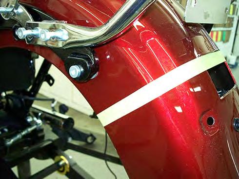
3 APPLICATION: Trike conversion kit for Harley-Davidson Touring motorcycles PRODUCT: HDT VERSION: & newer model year only GENERAL NOTES: Please don t attempt any shortcuts. 1. CHECK THE ENTIRE MOTORCYCLE FOR PROPER OPERATION AND/OR FLAWS BEFORE STARTING THIS CONVERSION PROCESS 2. DISCONNECT THE BATTERY 3. HOW THE HDT CONVERSION CHASSIS IS SHIPPED TO YOU a. See PIC #1 b. Double check the parts list against what you received in the shipping crate. 4. REMOVE THE FOLLOWING ITEMS FROM THE MOTORCYCLE a. Seat: (save - if the seat has a strap, discard it) b. Side covers: (save) c. Saddlebags and mounts: (discard) d. Tour pack with mounting rack: (save the tour pack, mounting rack, and hardware) e. Remove and discard the left & right chrome fender strut/saddlebag mounting covers and any associated hardware f. Passenger footrests: (save)(discard the bolts from the right side) g. Mufflers (save) i. Discard the four 5/16 x ½ muffler mounting bracket bolts ii. Save all other muffler mounting hardware: (2) brackets, (4) lock-washers (2) rubber isolators (2) clamps iii. Note the position of the rubber isolators h. Rear wheel and brake caliper: (discard) i. Discard the banjo bolt & sealing washers ii. Leave the rubber brake hose on the bike (remove it from the clips on the swing arm) iii. If equipped with ABS remove and save the pickup ring i. Swing arm assembly: (discard) i. Supporting the engine/transmission assembly before removing the pivot shaft and Left side mounting bracket will save time during re-assembly ii. Remove and save the left side swingarm mounting bracket and rubber swing arm mount iii. NOTE- the right side rubber mount can remain in place iv. Discard the stock bolts and lock washers from the left side swingarm mounting bracket. v. Remove and discard the stock pivot shaft, bolts, and cup washers j. Tail light assembly: i. Save the lens and base (discard the tail light base to fender mounting bolt) ii. Remove and discard the tail light extension harness k. Kick stand (discard) 5. CUTTING THE REAR FENDER a. Mark the rear fender: (PIC #2 & 3) i. Using the top edge of the tail light opening as a guide, extend it to approx. 3 ½ from the center of the fender ii. Now create a line from there to just under (approx. ¼ ) the chrome fender bracket cover iii. Cut the fender along your lines to the tail light opening - leave the tail light mounting tab. iv. De-burr the edge and install the push on rubber trim (Bag #2) from the kit v. The fender cut is not critical. The trike body completely covers it (PIC #4) 6. CHANGE THE BELT a. Using your HD service manual as a guide, replace the stock belt with the Gates belt provided in the kit. Listed below are some common torque specifications.
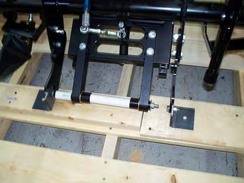
4 APPLICATION: Trike conversion kit for Harley-Davidson Touring motorcycles PRODUCT: HDT VERSION: & newer model year only GENERAL NOTES: Please don t attempt any shortcuts. Primary cover screws Primary chain-case to engine and trans bolts Compensating sprocket nut Clutch hub nut 7-9 (ft-lb) (ft-lb) (ft-lb) (ft-lb) Belt tension Swing arm pivot bolt 10 lbs force with 1/4-3/8 deflection 50 (ft-lb) 7. REMOVE THE CONVERSION BODY FROM THE CHASSIS: a. Discard the hardware b. If the kit was ordered with the reverse option: i. Raise the reverse lever ii. Un-snap and open the Velcro seam on the reverse boot iii. Lift the body forward and up to clear the reverse lever 8. REMOVE THE PARTS SHOWN (PIC #5) from the Trike chassis a. Note the location of the hardware for re-assembly b. If the kit was ordered with the reverse option, remove the reverse lever/bracket assembly from the frame and swing arm and set it aside for re-installation later. i. Save the (2) 5/16 X 1 reverse lever mounting bracket bolts and lock nuts ii. Remove the reverse cable assembly from the swing arm by removing the L shaped rear cable anchor from the swing arm (Allen head screw (save) keep track of (save) the alignment pin located between the rear cable anchor and the swing arm for re-installation later) 9. REMOVE THE SWING ARM ASSEMBLY FROM THE TRIKE CHASSIS (PIC#6) Leave the swing arm support bars connected to the swingarm a. Discard the shipping hardware (PIC #7 & 8) i. Thru-bolt ii. Sleeve iii. Washers iv. Nuts v. Spacers 10. REMOVE THE DIFFERENTIAL ASSEMBLY (PIC #9) a. The swing arm rails and bearing clamp blocks are match numbered (to identify mating parts) b. If the kit was ordered with the reverse option: i. Remove the reverse motor assembly from the swing-arm (PIC #10) ii. Remove the front return spring anchor and spring from the adjuster block(leave the spring on the reverse motor bracket) iii. Remove the right side reverse motor pivot block to separate the reverse motor assembly from the swing arm iv. Keep track of the wave washers (one on each end of the pivot shaft) 11. REMOVE THE REMAINING PARTS FROM THE CHASSIS (PIC #11) a. Left and right front frame mounting plates b. Note: leave the right front frame mounting plate assembly bolted together as shown c. Rear cross bar with trailer hitch/body mount supports attached
5 APPLICATION: Trike conversion kit for Harley-Davidson Touring motorcycles PRODUCT: HDT VERSION: & newer model year only GENERAL NOTES: Please don t attempt any shortcuts. 12. SEPARATE THE FRONT AND REAR SWING ARM SECTION AS SHOWN (PIC #12) 13. ASSEMBLE SWING ARM PIVOT SHAFT ASSEMBLY a. See Diagram A & (PIC #13) b. NOTE: Use the provided cup washers & nuts on both ends of The Trike Shop provided pivot shaft. c. Install the (2) bronze shouldered bushings (from BAG #1) in to the transmission pivot shaft bore as shown in diagram A d. Coat the pivot shaft with anti-seize e. Install and tighten (1) stock cup washer and nut on The Trike Shop pivot shaft before installation 14. INSTALL THE SWING-ARM FRONT SECTION a. Install the front section as shown in diagram A INSTALL THE STOCK SWING-ARM MOUNTING BRACKET AND THE TRIKE SHOP FRONT FRAME MOUNTING PLATES a. LEFT SIDE See (PIC #14) & (PIC #15) b. Remove the 3/8 bolt connecting the left rear frame tubes- discard the bolt- save the washer c. Use (2) 7/16 x 1¼ stainless steel socket head cap screws and (1) 3/8 x 1 3/4 bolt (from bag #2) (re-use the stock washer on this bolt) to attach the left side frame mounting plate and the stock swing arm mounting bracket use Locktite only, no lock-washers d. When installing the swing-arm mounting bracket and Trike Shop front frame mounting plate, ensure that index tabs on the swing-arm mounting bracket(left side) & frame (right side) fully engage the slots in the rubber transmission mounts e. Tighten the (2) socket head cap screws, the 3/8 bolt and the pivot shaft nut now f. Now back off just the socket head cap screws and the 3/8 bolt about one turn g. (PIC #15) shows the left front chassis mounting plate and the front of the swing-arm installed before installing the cup washer and nut h. RIGHT SIDE i. Remove the lower exhaust shield- (save) (PIC #16) ii. Remove the 3/8 bolt connecting the right rear frame tubes- discard the bolt- save the washer. iii. Install the right side front frame mounting plate assembly - Use (1) 3/8 x 1 ¼ & (1) 5/16 x 1 ¾ Allen bolt, & (1) 3/8 x 2 hex head bolt (from bag #2) (re-use the stock washer on this bolt) to attach the right side frame mounting plate assembly iv. Install the 3/8 x 2 bolt and washer through the plate assembly and into the HD frame tube threaded hole, turn it in but do not tighten yet: NOTE: When installing this bolt, a slight lift on the rear of the fender struts may be needed to get the two HD frame tube bolt holes to line up. v. Start the two Allen bolts through the upper and lower holes in the plate and into the upper and lower passenger foot peg mounting holes vi. Tighten the 3/8 x 2 bolt now, making sure that the two Allen bolts still turn freely (PIC #18) note: pic #18 shows the chassis already bolted to the right front frame mounting plate assembly- this is to help with parts association/identification 16. SEE PIC # 20 TRIKE CHASSIS STRIPPED AND READY FOR INSTALL 17. SLIP THE CHASSIS THROUGH THE BELT
6 APPLICATION: Trike conversion kit for Harley-Davidson Touring motorcycles PRODUCT: HDT VERSION: & newer model year only GENERAL NOTES: Please don t attempt any shortcuts. DRIVE BELT CAUTION! DO NOT TWIST, KINK, OR OTHERWISE DAMAGE THE BELT DURING INSTALLATION DAMAGING THE BELT DURING INSTALLATION WILL DRASTICALLY SHORTEN ITS SERVICE LIFE 18. ATTACHING THE TRIKE CHASSIS TO THE FRONT FRAME MOUNTING PLATES a. Attach the trike s chassis to the front frame mounting plates and the bike s upper shock mounting holes as shown in (PIC #21) b. NOTE: The two ¼ thick chassis mounting plates go to the outside of the front frame mounting plates. (PIC #21) c. 9/16 long spacers from (Bag #2) go between the plates and the bike frame upper shock mounting holes- use ½ x 1 ½ bolts and flat washers (Bag #2) (see diagram #A ) d. Tighten all related bolts: i. (2) 1/2 bolts ii. (6) 3/8 bolts iii. All left and right frame mount plate bolts leave the two foot peg bracket mounting Allen bolts on the right side loose for now- insure that they still turn freely. These will be tightened when the passenger foot pegs are installed. iv. Replace the exhaust shield 19. CONNECT THE STOCK BRAKE LINE TO THE HEX FITTING ON THE TRIKE CHASSIS (PIC #22) i. Use the provided banjo bolt (3/8-24 thread) 20. BLEED THE REAR BRAKES a. Use the TOP bleeders only 21. INSTALL THE 3/8 x 1 ¼ BOLT & LOCKNUT THROUGH THE TAB ON THE TRIKE CHASSIS AND THE STABILIZER LINK a. See (PIC #23) b. Tighten the bolt for now, we will adjust the stabilizer link later 22. INSTALL THE REAR SECTION OF THE SWING ARM a. See (PIC #24) b. Push the rear swing arm all the way forward. c. For now, only snug the nuts and cam bolt nuts enough so that there is no slop, yet the swing arm can still be adjusted. We will tighten everything later. 23. INSTALL THE CROSSBAR a. See. (PIC #25) Start the (4) 3/8 x 1 bolts and locknuts 24. INSTALL LEFT AND RIGHT SWING-ARM SUPPORT RODS a. See (PIC #26) b. Raise the swing-arm to install the support rods c. Tighten the crossbar bolts and the swing arm support rod bolts (The top of the support rods go to the outside of the crossbar brackets) 25. FOR TRIKES WITH REVERSE a. See (PIC #27) b. Replace the motor assembly, but NOT the cable c. Make sure that the two wave washers are on the reverse pivot shaft (one on each end) d. Replace the return spring anchor, with the spring attached to it and the reverse motor bracket, in to the adjuster block.
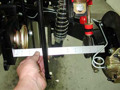
7 APPLICATION: Trike conversion kit for Harley-Davidson Touring motorcycles PRODUCT: HDT VERSION: & newer model year only GENERAL NOTES: Please don t attempt any shortcuts. 26. INSTALL THE DIFFERENTIAL ASSEMBLY AND INSTALL THE BELT ON TO THE SPROCKET a. See (PIC #28) 27. INSTALL THE SWAY BAR ASSEMBLY a. See (PIC #29) b. Tighten the end links first c. Then the pivot bushings last 28. TIGHTEN THE BELT a. See (PIC #30) b. Using a 1 wrench on the hex crossbar, rotate the crossbar to the desired belt tension i. 10 lbs force with 1/4-3/8 deflection c. While holding tension on the hex crossbar i. Tighten the (4) nuts on the rear swing-arm ii. Tighten the bolts on the cams and iii. Tighten the left side swing-arm rail-to-hex crossbar center bolt d. Rotate the sprocket a few times to check the belt tracking i. Make sure the belt is not rubbing anything 29. CENTERING THE SWING-ARM a. See (PIC #31) b. Using the stabilizer link, center the swing-arm assembly between the outer axle flanges and the swing arm rails. c. The measurement needs to be the same on each side. d. Tighten the stabilizer adjustment jam nuts 30. INSTALL ABS SENSOR (IF EQUIPPED) (SEE PICS 31-A, 31-B, 31-C, 31-D and 31-E) To install the ABS sensor onto the mounting block on the right side swing arm rail bearing cap: Remove the block from the bearing cap Install the sensor on the block so that the wire is pointing STRAIGHT UP and angling away from the ring Replace the block with the sensor attached Route the wire along the lower edge of the fender strut, zip tie carefully to avoid conflict with the tour pack rack (if equipped) plug in the provided extension wire to reach the plug under the right side cover 31. INSTALL THE DRIVE AXLE ASSEMBLIES See (PIC #32) a. Both axles and ends are the same, no inside, outside, etc. b. Using a cross pattern, tighten to 28+ ft-lb 32. FOR TRIKES WITH REVERSE a. Temporarily Install the reverse lever/cable assembly onto the Trike frame. See (PIC #33) b. Replace the rear cable anchor (with the cable still attached) on to the swing arm bearing cap. See (PIC #34) i. Note: Be sure to replace the locating pin between the rear cable anchor and the swingarm bearing cap c. Install the clevis onto the reverse motor assembly. See (PIC #35) d. Gently raise the reverse lever to engage the gear into the sprocket i. Ensure the gears mesh ii. Adjust the knob on the end of the lever so that just before the lever is fully extended, slight resistance is felt e. When the adjustment procedure is complete
8 APPLICATION: Trike conversion kit for Harley-Davidson Touring motorcycles PRODUCT: HDT VERSION: & newer model year only GENERAL NOTES: Please don t attempt any shortcuts. i. Install the cotter pin f. Install the reverse wiring i. Refer to Diagrams #A A (REV D), Diagram #A B-14 and (PIC #36) ii. Note: Pic #36 shows where to access the white neutral wire to install the T tap 33. INSTALL THE BODY MOUNT/TRAILER HITCH ASSEMBLY a. See (PIC #37) b. Install the front of the body-mount / trailer-hitch assembly first. c. Install the rear mounting bolts through the support arms, to the body-mount / trailer-hitch as shown and tighten all related bolts. 34. INSTALL THE EXHAUST SYSTEM a. See (PIC #38) b. Use the stock exhaust system plus the supplied exhaust extension pipes and clamps. The extensions slip between the stock exhaust and the mufflers. c. Install the stock muffler s hangers and rubber mounts into the openings on the body-mount / trailerhitch assembly d. Replace the (4 discarded)stock 5/16 x ½ muffler hanger bolts with (4) 5/16 x ¾ bolts from (bag #3) e. Install the ¼ chrome spacers (bag #3) between the mufflers and the hanger brackets f. Tighten the four muffler hanger bolts now- not the muffler clamps yet. 35. PREPARATION FOR BODY INSTALLATION a. Temporarily remove the two rear 3/8 bolts connecting the support arms to the body mount/trailer hitch assembly. This will allow the rear of the body mount/trailer hitch assembly to drop about 2. b. If equipped with the reverse option i. To install the body the reverse lever must be temporarily separated from the frame ii. Unplug the wiring and remove the two reverse lever mounting bolts from the frame - set the lever/cable assembly down on the frame. 36. BODY PREPARATION a. Install the two provided tail light bases on to the trike body using the hardware from (BAG #4) i. In test fitting the bases, notice that they may not sit flush with the body. To make them fit flush with the body, grind off the lower outside corners of the tail light bases(pic #39) ii. After you are content with the fit, install the bases on to the body b. After lightly bolting down the bases, drill a 3/16 hole through the bases and the body at the location shown in (PIC #40) i. Install the #8-32 (bag #4) stainless screws to draw down and hold the tail light bases c. Install the turn signals using the stock fasteners i. Make sure that the turn signals are square with the tail light lenses - adjust them as needed before tightening (adjusting the turn signals may require slight grinding of the mounting screw holes in the body) 37. TAIL-LIGHT WIRING HARNESS AND ASSOCIATED WIRING a. See Diagram #A D b. Connect the wiring as shown c. Attach the harness to the tail light mounting bolt using the ¼ p-clamps and ¼ locknuts from (bag #5) (PIC #41) d. Attach the harness to the trunk walls (PIC #41) using the screws and 5/16 plastic cable clamps and nuts from (Bag #5) e. Install the license plate frame and the license plate light (bag #7)
9 APPLICATION: Trike conversion kit for Harley-Davidson Touring motorcycles PRODUCT: HDT VERSION: & newer model year only GENERAL NOTES: Please don t attempt any shortcuts. 38. RUBBER EDGE TRIM ( this section applies to un-painted bodies only.) a. See (PIC #42) b. Install push-on rubber edge trim on the inside opening of the body c. Thoroughly clean the edge before installing the trim d. The rubber trim has pre-applied glue in it i. During installation, lightly tapping on the trim helps to break the membrane on the glue for better adhesion 39. INSTALL THE BODY a. Keeping track of the tail light wiring harness (tape it to the top of the body), and with the help of an assistant i. Carefully set the body onto the chassis 1. install the body by rotating it enough to slide the rear tour pack opening under the tour pack rack while placing it on top of the front body mounts a. Then rest the rear of the body on to the chassis. b. Lift the body mount/trailer hitch assembly to replace and tighten the rear mounting bolts c. Now tighten the muffler clamps carefully- making sure that the mufflers stay aligned and are not touching anything 40. ROUTING THE TAIL-LIGHT HARNESS AND SECURING THE BODY a. Route the tail-light harness along the fender and zip tie it under the rear frame rail extension b. Plug in the harness to the mating plug on the fender i. Check the function of all lights ii. After checking the lights, check the wiring harness routing, and zip tie it as needed c. Install the front and rear body mount bolts (Bag #8) through the pre-drilled holes in the body i. The pre-drilled body mount holes should be very close - there should not be much adjustment needed ii. Install the front bolts pointing up - install the rear bolts pointing down iii. Put the washers between the fastener and the fiberglass iv. Before tightening the bolts 1. check the body position a. adjust if needed then i. tighten all six body mount bolts v. After bolting down the body, open and close the door 1. Making sure that the door latches on the second detent of the latch 2. Adjust the latch if needed 3. A somewhat firm push on the door to make it latch is normal as over time the weather stripping tends to conform to its mating surface 4. If equipped with the reverse option, guide the end of the reverse lever through the hole in the body, replace the mounting bolts, and plug in the wiring 5. (NOTE): remove the left rear wheel to access the reverse lever/plugs 41. TRIM THE SIDE COVERS a. See (PIC #43) b. Using the provided side cover marking templates cut the side covers along the line c. Remove the rear upper side cover mounting peg from both side covers (grind off all raised areaflush to the cover) d. Carefully test fit the covers to the frame and body and trim and de-burr as needed e. Install push on rubber edge trim (if desired) (bag #2)
10 APPLICATION: Trike conversion kit for Harley-Davidson Touring motorcycles PRODUCT: HDT VERSION: & newer model year only GENERAL NOTES: Please don t attempt any shortcuts. f. Install the two ½ x ½ bolts (bag #6) into the rear upper side cover grommets (1 on each side) (PIC #44) g. Stick one set of adhesive backed self lock fasteners (bag #6) to each bolt h. Make sure the ground area on the covers is clean, peel the film off of the fasteners, (already on the bolt heads), install the cover making sure to start the two remaining pegs first, then firmly push on the area over the fastener to seat the adhesive. (PIC #45) i. See (PIC #46) - you need about ½ of clearance between the side cover and the body 42. CONNECT THE BATTERY 43. REPLACE THE FUEL TANK- (IF IT WAS REMOVED) 44. REPLACE THE TOUR PACK & RACK ASSEMBLY (STOCK HARDWARE) 45. REPLACE THE SEAT USING STOCK HARDWARE 46. REPLACE THE PASSENGER FOOTRESTS Use the stock bolts on the left side Use the Allen bolts & shoulder bushing from bag #2 on the right side lower foot peg bracket bolt. (This bushing replaces the shouldered area on the stock bolt) 47. REPLACE THE ROUND SWING ARM PIVOT BOLT COVERS (PUSH ON) 48. CHECK THE TORQUE ON THE LUG NUTS (70-75 FT LBS) 49. TEST DRIVE
11
12
13
14
15

16

17

18

19

20

21

22

23

24

25
26

27

28

29

30

31

32

33

34

35

36

37

38
39

40

41

42

43

44

45

46

47

48

49

50

51

52

53

54

55

56

57

58

59

60

61

62
63

64

65
R O A D S M I T H TRIKE CONVERSIONS BY THE TRIKE SHOP
 R O A D S M I T H TRIKE CONVERSIONS BY THE TRIKE SHOP Please thoroughly review the instructions before and during installation. Keep in mind that this product was designed to be installed by trained dealer
R O A D S M I T H TRIKE CONVERSIONS BY THE TRIKE SHOP
 R O A D S M I T H TRIKE CONVERSIONS BY THE TRIKE SHOP Please thoroughly review the instructions before and during installation. Keep in mind that this product was designed to be installed by trained dealer
R O A D S M I T H TRIKE CONVERSIONS BY THE TRIKE SHOP
 R O A D S M I T H TRIKE CONVERSIONS BY THE TRIKE SHOP Please thoroughly review the instructions before and during installation. Keep in mind that this product was designed to be installed by trained dealer
R O A D S M I T H TRIKE CONVERSIONS BY THE TRIKE SHOP
 R O A D S M I T H TRIKE CONVERSIONS BY THE TRIKE SHOP Please thoroughly review the instructions before and during installation. Keep in mind that this product was designed to be installed by trained dealer
R O A D S M I T H TRIKE CONVERSIONS BY THE TRIKE SHOP
 R O A D S M I T H TRIKE CONVERSIONS BY THE TRIKE SHOP Please thoroughly review the instructions before and during installation. Keep in mind that this product was designed to be installed by trained dealer
2010+ Victory Cross Country / Cross Roads Installation Guide Nov 2014
 2010+ Victory Cross Country / Cross Roads Installation Guide Nov 2014 125 Industrial Drive Spearfish, SD 57783 Toll Free 888.3WHEELS w w w. l e h m a n t r i k e s. c o m UNDERSTANDING SAFETY LABELS &
KIT # CSS-C SUSPENSION LIFT KIT
 14385 Veterans Way Moreno Valley, CA 92553 Phone: (951) 571-0212 Fax: (951) 571-0215 2001-2010 CHEVROLET SILVERADO 1500 AND 2500 HD 4WD AND 2WD PICK-UP 1999-2010 CHEVY 2500 4WD PICK-UPS 2001-2010 2500
AEV30308AA Last Updated: 05/31/18. 4 DUALSPORT sc SUSPENSION system for RAM 1500 air ride standard and rebel INSTALLATION GUIDE
 AEV30308AA Last Updated: 05/31/18 4 DUALSPORT sc SUSPENSION system for RAM 1500 air ride standard and rebel INSTALLATION GUIDE PLEASE READ BEFORE YOU START TO GUARANTEE A QUALITY INSTALLATION, WE RECOMMEND
ALL DIRECTIONS/REVISIONS WERE COMPILIED ON
 R O A D S M I T H TRIKE CONVERSIONS Please thoroughly review the instructions before and during installation. Keep in mind that this product was designed to be installed by trained dealer technicians.
Trike Conversion Kit. KAWASAKI 1700 Vulcan Voyager Vulcan Vaquero Vulcan Nomad. Installation Instructions
 BY Trike Conversion Kit KAWASAKI 1700 Vulcan Voyager Vulcan Vaquero Vulcan Nomad Installation Instructions REVISED 1-2015 California Sidecar Parts & Technical Support 434.263.8866 Table of Contents: 1.
Trike Conversion Installation Guide Kawasaki Vulcan 900 Classic, Classic LT, and Custom Models 2007 and Up Solid Axle Suspension
 Trike Conversion Installation Guide Kawasaki Vulcan 900 Classic, Classic LT, and Custom Models 2007 and Up Solid Axle Suspension CAUTION: -Failure to make the proper adjustments will potentially lead to
Current. Installation Instructions
 by Trike Conversion Kit 2004 - Current Harley-Davidson Sportster Installation Instructions REVISED 4-2017 California Sidecar Parts & Technical Support 434.263.8866 Table of contents: 1. Warnings and Considerations
Trike Conversion Kit ROADLINER, STRATOLINER, & STRATOLINER DELUXE
 by Trike Conversion Kit ROADLINER, STRATOLINER, & STRATOLINER DELUXE Installation Instructions Revised 1-2015 California Sidecar Parts & Technical Support 434.263.8866 Table of Contents: 1. Warnings and
Cobra & Cobra XL. Trike Conversion Kit GL1800 Goldwing. Installation Instructions. California Sidecar Parts & Technical Support
 Cobra & Cobra XL by Trike Conversion Kit 2001-2010 GL1800 Goldwing Installation Instructions REVISED 1-2015 California Sidecar Parts & Technical Support 434.263.8866 Table of contents: 1. Maintenance Schedule
Installation Instructions
 By Trike Conversion Kit for INDIAN MOTORCYCLES CLASSIC - VINTAGE - DARKHORSE CHIEFTAN & ROADMASTER MODELS 2014 - CURRENT Installation Instructions Revised 4-2017 California Sidecar Parts & Technical Support
-Failure to make the proper adjustments will potentially lead to serious personal injury and/or property damage and may void the warranty.
 Trike Conversion Installation Guide Victory Cross Roads Classic and 8-Ball Victory Cross Country/Tour/8-Ball and Ness Cross Country Limited-Edition and Up Independent Suspension Rev. 1 CAUTION: -Failure
Trike Conversion Installation Guide for Harley-Davidson Sportster Motorcycles 2004 & Up Revision 7
 Trike Conversion Installation Guide for Harley-Davidson Sportster Motorcycles 2004 & Up Revision 7 CAUTION : Failure to follow these instructions can lead to serious personal injury and/or property damage
INSTALLATION INSTRUCTIONS FOR THE TOMAHAWK ELECTRIC REVERSE
 INSTALLATION INSTRUCTIONS FOR THE TOMAHAWK ELECTRIC REVERSE LAST UPDATED: April 2018 Thank you for choosing the Motor Trike Electric Reverse. We ask that you read the directions before you start and follow
CALIFORNIA SIDECAR TRIKE CONVERSION KIT INSTALLATION INSTRUCTIONS VALKYRIE INTERSTATE
 CALIFORNIA SIDECAR TRIKE CONVERSION KIT INSTALLATION INSTRUCTIONS VALKYRIE INTERSTATE FOR INSTALLATION ASSISTANCE, CALL PARTS & TECHNICAL SUPPORT @ (434) 263-8866 TABLE OF CONTENTS SECTION PAGE Table of
Installation Notes: #86000-R Race Series +3.5 L/T Kit
 159 North Maple St. Unit J, CORONA CA 92880 P. 951-737-9682 F. 951-737-9006 WWW.CHAOSFAB.COM Installation Notes: #86000-R Race Series +3.5 L/T Kit Factory manual is recommended for removal and re-installation
SPORTSTER SADDLEBAG KIT. i i02212
 General These saddlebags are designed to fit 99 and later Sportster Model Motorcycles, except XL00 Sport models with gas reservoir shock absorbers and 88R models. See the Service Parts pages for a list
INSTRUCTIONS DYNA FLOORBOARD KIT 1WARNING -J01921 REV General. Kit contents. Installation SHIFTER ASSEMBLY (LEFT SIDE) Kit Number
 Kit Number") General INSTRUCTIONS REV. 10-1-200 Kit Number 50601-01 DYNA FLOORBOARD KIT Kit contents This forward foot controls kit is designed for use on all 1996 and later FXD models and includes all parts required
General INSTRUCTIONS REV. 10-1-200 Kit Number 50601-01 DYNA FLOORBOARD KIT Kit contents This forward foot controls kit is designed for use on all 1996 and later FXD models and includes all parts required
Victory CrossRoads CrossCountry CrossCountry Tour HardBall
 by Trike Conversion Kit Victory CrossRoads CrossCountry CrossCountry Tour HardBall Installation Instructions Revised 3-2018 California Sidecar Parts & Technical Support 434.263.8866 Table of Contents:
Installation Instructions
 BY Trike Conversion Kit KAWASAKI Vulcan 900 CLASSIC- CLASSIC LT AND CUSTOM MODELS 2006-CURRENT Installation Instructions Revised 1-2015 California Sidecar Parts & Technical Support 434.263.8866 2 Table
GL1800 TRAILER HITCH - INSTALLATION INSTRUCTIONS #GL
 GL1800 TRAILER HITCH - INSTALLATION INSTRUCTIONS #GL18007-20 Read through these instructions completely before attempting installation, lay out all pieces including the numbered hardware bags to familiarize
Trike Conversion Installation Guide for Indian Scout Motorcycles 2016 & Up Revision 2
 Trike Conversion Installation Guide for Indian Scout Motorcycles 2016 & Up Revision 2 Warning - This product was not intended for more than one rider. Weight limit on this product has been set at 400 lbs.
STOP---READ THIS FIRST!
 STOP---READ THIS FIRST! **Read These Entire Instructions Before Starting Anything** 2007-2013 GM 1500 TRUCK LIFT KIT INSTRUCTIONS (PART# 50700 & 50720) 5680 W. Barstow, Fresno, CA 93722 PH: (559) 226-8196
STOP---READ THIS FIRST!
 STOP---READ THIS FIRST! **Read These Entire Instructions Before Starting Anything** 2007-2010 GM 1500 TRUCK LIFT KIT INSTRUCTIONS (PART# 50700 & 50720) 5680 W. Barstow, Fresno, CA 93722 PH: (559) 226-8196
2014 GM 1500 TRUCK STOP---READ THIS FIRST! 7" Lift KIT. **Read These Entire Instructions Before Starting Anything**
 STOP---READ THIS FIRST! **Read These Entire Instructions Before Starting Anything** 2014 GM 1500 TRUCK LIFT KIT INSTRUCTIONS (PART #50768 & #50769 ) 5680 W. Barstow, Fresno, CA 93722 PH: (559) 226-8196
Installation Instructions
 BY Trike Conversion Kit 2009 - Current FLHT Series Harley-Davidson Installation Instructions REVISED 7-2017 California Sidecar Parts & Technical Support 434.263.8866 2 Table of contents: 1. Warnings and
Trike Conversion Installation Guide for Zero Flex Solid Axle Wide Body Harley-Davidson FLH Series Motorcycles Revision 1
 Trike Conversion Installation Guide for Zero Flex Solid Axle Wide Body Harley-Davidson FLH Series Motorcycles 2014-2016 Revision 1 WARNING: Failure to follow these instructions can lead to serious personal
Safety - Installation and Operation:
 4x4 or 4x2 Instructions EZGO Electric Cars Thank you for purchasing your 4x4 or 4x2 conversion kit. Safety at all times whether during installation or operation is utmost importance. Before After!!!!!!!!!!!!!!
Trike Conversion Kit GL1800 Goldwing Current. Installation Instructions
 by Trike Conversion Kit GL1800 Goldwing 2012 - Current Installation Instructions REVISED 4-2015 California Sidecar Parts & Technical Support 434.263.8866 Table of contents: 1. Maintenance Schedule 5 2.
2018 UP GL1800 Gold Wing & Gold Wing Tour. Trike Kit Installation Instructions. California Sidecar Parts & Technical Support
 by 2018 UP GL1800 Gold Wing & Gold Wing Tour Trike Kit Installation Instructions California Sidecar Parts & Technical Support 434.263.8866 2 Table of contents: 1. Maintenance Schedule 5 2. Disassembly
RAIDER to 2016 XL MODELS *Will not fit XR1200 models *Nightster, Forty-Eight and Iron 883 models may require additional modifications
 RAIDER 2014 to 2016 XL MODELS *Will not fit XR1200 models *Nightster, Forty-Eight and Iron 883 models may require additional modifications **Installation should be installed by a qualified mechanic INSTALLATION
INSTALLATION INSTRUCTIONS
 INSTALLATION INSTRUCTIONS Document# 19-0038 2004+ Lotus Elise (Series 2) Rear Clamshell Removal Kit Safely support the vehicle. This is a two-person job. Allow 1 to 2 hours for initial disassembly. Have
INSTALLATION INSTRUCTION 89400
 INSTALLATION INSTRUCTION 89400 FOR RANCHO SUSPENSION SYSTEM RS66400B: 2012 RAM 1500 4WD. READ ALL INSTRUCTIONS THOROUGHLY FROM START TO FINISH BEFORE BEGINNING INSTALLATION Rev B IMPORTANT NOTES! WARNING:
INSTALLATION INSTRUCTION Rev A
 INSTALLATION INSTRUCTION 88587 Rev A FOR RANCHO SUSPENSION SYSTEM RS6587B: 2009 DODGE RAM 1500 READ ALL INSTRUCTIONS THOROUGHLY FROM START TO FINISH BEFORE BEGINNING INSTALLATION IMPORTANT NOTES! WARNING:
INSTALLATION INSTRUCTION 88581
 INSTALLATION INSTRUCTION 88581 FOR RANCHO SUSPENSION SYSTEM RS6581B: DODGE RAM READ ALL INSTRUCTIONS THOROUGHLY FROM START TO FINISH BEFORE BEGINNING INSTALLATION Rev C IMPORTANT NOTES! WARNING: This suspension
'99-03 CHEVROLET/GMC IFS 4WD 6" SUSPENSION SYSTEM P/N INSTALLATION INSTRUCTIONS
 1/16/04 '99-03 CHEVROLET/GMC IFS 4WD 6" SUSPENSION SYSTEM P/N. 10-41099 INSTALLATION INSTRUCTIONS NOTE: Each Lift Kit and options to Lift Kits are packaged separately. Therefore, installation procedures
Suspension System RS6582B
 Suspension System RS6582B Tahoe/Yukon READ ALL INSTRUCTIONS THOROUGHLY FROM START TO FINISH BEFORE BEGINNING INSTALLATION IMPORTANT NOTES! WARNING: This suspension system will enhance the off-road performance
Installation Instructions
 BY Trike Conversion Kit 1999 2008 FLHT Series Harley-Davidson Installation Instructions REVISED 4-2017 California Sidecar Parts & Technical Support 434.263.8866 Table of contents: 1. Warnings and considerations
Installation Instructions
 Installation Instructions for Harley Tri-Glide Trike Step 1 Step 2 Remove trike body and set aside Disassemble the rear suspension. Set aside the differential, ring gear, pulley, differential clamps, wheel
INSTALLATION INSTRUCTIONS
 INSTALLATION INSTRUCTIONS 2005-2012 Nissan Xterra/Frontier / Pathfinder PART NUMBERS: NP17500, NP17525, NP17550 FRONTIER PARTS & CORRESPONDING HARDWARE LIST XTERRA PATHFINDER ABOVE LISTED 1/2 Metal Lock
INSTALLATION INSTRUCTIONS
 INSTALLATION INSTRUCTIONS Accessory HITCH Application 2009 CR-V Publications No. AII 40373 Issue Date AUG 2008 PARTS LIST Plain washer, 12 mm Trailer Hitch Kit P/N 08L92-SWA-100 Trailer hitch 6 Spring
Installation Manual TWM Performance Short Shifter Subaru STi 2008+
 - 1 - Installation Manual TWM Performance Short Shifter Subaru STi 2008+ Please Note: It is preferable to park on a flat surface, as you will have to engage and disengage the hand brake and shift from
Installation Instructions HURST COMPETITION AND BILLET/PLUS SHIFTER Mustang w/5-speed Manual Transmission (GT only)
") Installation Instructions HURST COMPETITION AND BILLET/PLUS SHIFTER 2005-2010 Mustang w/5-speed Manual Transmission (GT only) Catalog# 3915201 WORK SAFELY! For maximum safety, perform this installation
Installation Instructions HURST COMPETITION AND BILLET/PLUS SHIFTER 2005-2010 Mustang w/5-speed Manual Transmission (GT only) Catalog# 3915201 WORK SAFELY! For maximum safety, perform this installation
'88-'00 CHEVROLET/GMC IFS 4WD(8LUG) OLD BODY STYLE 6" SUSPENSION SYSTEM P/N
 OLD BODY STYLE 6 SUSPENSION SYSTEM P/N") 4/10/13 '88-'00 CHEVROLET/GMC IFS 4WD(8LUG) OLD BODY STYLE 6" SUSPENSION SYSTEM P/N. 10-41888 INSTALLATION INSTRUCTIONS APPLICATION WARNING: Applicable for hub mounted ABS sensor models only. Not for 1992-94
4/10/13 '88-'00 CHEVROLET/GMC IFS 4WD(8LUG) OLD BODY STYLE 6" SUSPENSION SYSTEM P/N. 10-41888 INSTALLATION INSTRUCTIONS APPLICATION WARNING: Applicable for hub mounted ABS sensor models only. Not for 1992-94
Trike Conversion Installation Manual. All Models
 Trike Conversion Installation Manual For Honda VTX 1300 Motorcycles All Models Revision 4 Mar. 2011 CAUTION: Failure to follow these instructions can lead to serious personal injury and/or property damage
Trike Conversion Kit GL1500 Goldwing
 BY Trike Conversion Kit 1988-2000 GL1500 Goldwing Installation Instructions Revised 3-2018 California Sidecar Parts & Technical Support 434.263.8866 Table of contents: 1. Maintenance Schedule 5 2. Disassembly
TOYOTA FJ CRUISER 6 SUSPENSION KIT
 92177000 TOYOTA FJ CRUISER 6 SUSPENSION KIT Thank you for choosing Rough Country for your suspension needs. Rough Country recommends a certified technician installs this system. In addition to these instructions,
ST - HD - HDXL Model
 ST - HD - HDXL Model TOOLS REQUIRED FOR ASSEMBLY OF THE TANDEM TOW DOLLY Ratchet Socket Wrench with sockets sizes: 7/16, 9/16, 3/ 4 & 15/16 7/16 Box or Open End Wrench 9/16 Box or Open End Wrench 3/4 Box
I. Before starting installation
 5. Park the vehicle on a clean, dry, flat, level surface and block the tires so the vehicle cannot roll in either direction. A. Disconnect battery cables 1. Disconnect the negative cable first, then the
»Product» Safety Warning
 #F2622 Installation Instructions 1997-2003 Ford F-150 4WD 6" Suspension System Read and understand all instructions and warnings prior to installation of product and operation of vehicle. Zone Offroad
SUT-450-I ASSEMBLY REQUIREMENTS
 SUT-450-I Torque wrench, carpenters square, wire cutters, Phillips screwdriver, 7/16, 9/16, and 3/4 combination wrenches, ratchet, 9/16,3/4,13/16, and 7/8 sockets. ASSEMBLY REQUIREMENTS *Torque all T-bolt
PRE-INSTALLATION. INSTALLATION INSTRUCTIONS Front Dodge Ram WD 6" Suspension Lift Kit
 2012-2015 Dodge Ram 1500 4WD 6" Suspension Lift Kit PRE-INSTALLATION 35015 2 - Knuckle (Driv/Pass) 2 - Crossmember (Front/Rear) 2 - Differential Bracket (Driv/Pass) 1 - Diff. Brace Bracket (Pass) 2 - Front
w w w. h d o n l i n e s h o p. d e LAYBACK LICENSE PLATE AND TURN SIGNAL RELOCATION KIT INSTALLATION GENERAL -J03892 REV Kit Number
 -J0 REV. 00-0-0 LAYBACK LICENSE PLATE AND TURN SIGNAL RELOCATION KIT GENERAL Kit Number 0-0 Models For model fitment information, please see the P&A Retail Catalog or the Parts and Accessories section
INSTALLATION INSTRUCTIONS DODGE DAKOTA 2 KIT # 682 (2WD), 692 (4WD) 3 KIT # 683 (2WD), 693 (4WD)
, 692 (4WD) 3 KIT # 683 (2WD), 693 (4WD)") INSTALLATION INSTRUCTIONS 1997-1999 DODGE DAKOTA 2 KIT # 682 (2WD), 692 (4WD) 3 KIT # 683 (2WD), 693 (4WD) Installation of a Performance Accessories body lift kit will change the vehicle s center of gravity
INSTALLATION INSTRUCTIONS 1997-1999 DODGE DAKOTA 2 KIT # 682 (2WD), 692 (4WD) 3 KIT # 683 (2WD), 693 (4WD) Installation of a Performance Accessories body lift kit will change the vehicle s center of gravity
97-06 JEEP TJ/LJ LONG ARM UPGRADE KIT
 921663U00 97-06 JEEP TJ/LJ LONG ARM UPGRADE KIT Thank you for choosing Rough Country for your suspension needs. This kit is an upgrade kit only. This kit includes frame mounting points and adjustable long
Jeep Wrangler (JK) Present
 Present") Suspension System RS66110B (3 SPORT SYSTEM w/ Progressive Coil Springs Front & Rear) 2012 NEWER JEEP MODELS EQUIPPED WITH 3.6L V6 ENGINE NEED EXHAUST MODIFICATION KIT RS720003. OR REPLACEMENT FRONT DRIVESHAFT
Suspension System RS66110B (3 SPORT SYSTEM w/ Progressive Coil Springs Front & Rear) 2012 NEWER JEEP MODELS EQUIPPED WITH 3.6L V6 ENGINE NEED EXHAUST MODIFICATION KIT RS720003. OR REPLACEMENT FRONT DRIVESHAFT
Installation Manual TWM Performance Short Shifter Cobalt SS/SC, SS/TC, HHR SS, Ion Redline and Saab 9-3
 Page 1 Installation Manual TWM Performance Short Shifter Cobalt SS/SC, SS/TC, HHR SS, Ion Redline and Saab 9-3 Please Note: It is preferable to park on a flat surface, as you will have to engage and disengage
INSTRUCTIONS SCREAMIN EAGLE FLHT 6-SPEED TRANSMISSION 1WARNING -J03322 REV Installation. General. Prepare the Motorcycle for Service
 INSTRUCTIONS REV. 02-11-2005 Kit Number 33136-04 and 33137-04 SCREAMIN EAGLE FLHT 6-SPEED TRANSMISSION General The Screamin Eagle FLHT 6-Speed Transmission kit fits 2002 and later Harley-Davidson Touring
INSTALLATION INSTRUCTIONS
 INSTALLATION INSTRUCTIONS Accessory HITCH Application 2012 CROSSTOUR Publications No. AII 46198 Issue Date JULY 2011 PARTS LIST Trailer Hitch Kit P/N 08L92-TP6-101 Upper spacer A (5 mm) (Some are not used.)
INSTALLATION INSTRUCTION 88073
 INSTALLATION INSTRUCTION 88073 Rev C FOR RANCHO SUSPENSION SYSTEMS RS6572 & RS6573: DODGE RAM READ ALL INSTRUCTIONS THOROUGHLY FROM START TO FINISH BEFORE BEGINNING INSTALLATION IMPORTANT NOTES! WARNING:
INSTALLATION INSTRUCTION 88088
 INSTALLATION INSTRUCTION 88088 For Rancho Suspension Systems RS6588 & RS6589: FORD F-150 READ ALL INSTRUCTIONS THOROUGHLY FROM START TO FINISH BEFORE BEGINNING INSTALLATION Rev B IMPORTANT NOTES! WARNING:
»Product» Safety Warning
 #F2402 & F2602 Installation Instructions 2004-2008 Ford F-150 4wd 4-6" Lift System Read and understand all instructions and warnings prior to installation of product and operation of vehicle. Zone Offroad
CSS-C SUSPENSION LIFT KIT
 115 W. La Cadena Dr. Ste 100 Riverside, CA 92501 (951) 328-9902 phone (951) 328-9908 fax 2000-2006 CHEVROLET SILVERADO 1500 4WD CSS-C3-2 6-8 SUSPENSION LIFT KIT WARNING: CALIFORNIA SUPERTRUCKS RECOMMENDS
FORD F-250/350 SUPER DUTY 4WD FTS RADIUS ARM BOX KIT
 2005-2007 FORD F-250/350 SUPER DUTY 4WD FTS22099 10 RADIUS ARM BOX KIT 2005-2007 FORD F-250/350 SUPER DUTY 4WD FTS22099 10 RADIUS ARM BOX KIT Qua Part # Description FT30155 Hardware Kit 1 FT30125BK Custom
Page 1. File: Motolight caliper one-piece Harley Date: 8/15/2006
 Page 1 Harley-Davidson FL Caliper Mount Installation One-piece mounting brackets You should allow about two to three hours for installation. We suggest you use a well-lighted space for installation. PLEASE
Installation Instructions
 Installation Instructions 6 Suspension System FTS25005BK / FTS25006BK 2006-2012 Nissan Frontier 2wd/4wd SHORT BED ONLY Tool List: (not included) Floor Jack & Jack Stands Assorted Metric & S.A.E Sockets
FTS & 8 RADIUS ARM BOX KIT
 FTS22139 6 & 8 RADIUS ARM BOX KIT 2008-2015 FORD F-250/350 SUPER DUTY 4WD 2008 2015 FORD F-250/350 SUPER DUTY 4WD FTS22139 6 & 8 RADIUS ARM KIT FTS22139 6"&8" Radius Arm Box Kit FT30287 Hardware Kit Qty
NORTHSTAR TRAILERS. Assembly Guide for MULTISTAR Trailer
 NORTHSTAR TRAILERS Assembly Guide for MULTISTAR Trailer Congratulations! You are the proud owner of a NORTHSTAR trailer. Please follow the instructions and steps in this manual for proper assembly. TRAILER
Safety First. Please remember to always use SAFE shop practices when performing all service procedures.
 Safety First Please remember to always use SAFE shop practices when performing all service procedures. 2006 Update Manual January 2006 Country Clipper 2006 Update Manual Index Joystick Kill Switch Oil
GP1-R FULL EXHAUST SUZUKI GSX-R600 / GSX-R
 THIS EXHAUST SYSTEM IS DESIGNED FOR USE IN CLOSED COURSE RACING ONLY, AND IS NOT INTENDED FOR PUBLIC HIGHWAY USE. IN THE STATE OF CALIFORNIA, IT IS ILLEGAL TO MODIFY THE EMISSION CONTROL SYSTEM ON ANY
INSTRUCTIONS 1WARNING 6 SPEED TRANSMISSION SUPER KIT -J03481 REV General. Removal. Kit Number A
 INSTRUCTIONS -J03481 REV. 08-31-04 Kit Number 33100-03A 6 SPEED TRANSMISSION SUPER KIT General This kit fits 1990-1999 Softail and 1991-2000 Dyna model motorcycles. Requires separate purchase of cable
INSTALLATION TRUE DUAL HEADPIPES 497
 TRUE DUAL HEADPIPES 497 PARTS INCLUDED 1 Front Head Pipe 1 Rear Head Pipe 1 Front Heat Shield 1 Rear Heat Shield 1 Bracket (stamped 422-P) 1 Bracket (stamped 423-P) 2 1/2 x 1-1/4 Socket Head Cap Screw
INSTALLATION INSTRUCTIONS 97 FORD EXPEDITION
 INSTALLATION INSTRUCTIONS 97 FORD EXPEDITION 1. Read the instructions completely and carefully before you begin. Check the kit for proper contents (refer to the part s list and the picture diagrams). Before
If you have any difficulties at all, please give us a call. Thank you and enjoy your MetalCloak Products!
 PRODUCT: TJ/LJ 3.5 Dual Rate Lift RockSport Edition READ INSTRUCTIONS IN FULL BEFORE INSTALLATION. QUESTIONS? CALL 916-631-8071 M-F 7:00 AM 5:00 PM PST The MetalCloak experience includes the ease of installation
8" 4-LINK SUSPENSION SYSTEM. Ford Super Duty 4WD Part#:
 Part#: 013813 8" 4-LINK SUSPENSION SYSTEM Ford Super Duty 4WD 2011-2016 Rev. 051817 491 W. Garfield Ave., Coldwater, MI 49036. Phone: 517-279-2135 E-mail: tech-bds@sporttruckusainc.com Read And Understand
INSTALLATION INSTRUCTIONS
 INSTALLATION INSTRUCTIONS --1075 North Ave. Sanger, CA 93657-3539 local: 559-875-0222 fax: 559-876-2259 toll free: 800-445-3767-- 2505 Lowering Spindle Assembly Installation Instructions ½ TON SILVERADO
***THE OWNER'S MANUAL MUST BE GIVEN TO THE END USE CUSTOMER AFTER COMPLETING THE INSTALLATION.***
 INSTALLATION INSTRUCTIONS FOR THE MOTOR TRIKE HARLEY MECHANICAL REVERSE 1999-2006 FIVE SPEED FLH LAST UPDATED: OCTOBER 2011 AS THE INSTALLER OF THIS MECHANICAL REVERSE, YOU MUST BECOME FAMILIAR WITH PROPER
*1611BAG2* 1611BAG2 92PERF1611
 *1611BAG2* 1611BAG2 92PERF1611 97-06 JEEP TJ 2 1/2 X-SERIES SUSPENSION KIT Thank you for choosing Rough Country for your suspension needs. Rough Country recommends a certified technician installs this
Page 1. File: Motolight caliper one-piece Date: 8/14/2006
 Page 1 Caliper Mount Installation One-piece mounting brackets You should allow about two to three hours for installation. We suggest you use a well-lighted space for installation. PLEASE READ ALL THE INSTRUCTIONS.
Installation Instructions Z-Gate Shifter
 Installation Instructions Z-Gate Shifter Part Number 80681 1998, 2001 by B&M Racing and Performance Products The B&M Z-Gate shifter can be used in vehicles equipped with most popular three speed automatic
RS-2 SINGLE ACTION REAR BUMPER WITH TIRE CARRIER INSTALL MANUAL FOR JEEP WRANGLER ALL MODELS.
 RS-2 SINGLE ACTION REAR BUMPER WITH TIRE CARRIER INSTALL MANUAL FOR 2007-2016 JEEP WRANGLER ALL MODELS. Rear Bumper Installation Instructions 1) Remove factory rear bumper, (this includes all tow hitch
09-UP FORD F150 6 LIFT KIT
 92159800 09-UP FORD F150 6 LIFT KIT THANK YOU FOR CHOOSING ROUGH COUNTRY FOR YOUR SUSPENSION NEEDS. Rough Country recommends a certified technician install this system. In addition to these instructions,
ADVANCE ADAPTERS INC. P/N: JEEP TJ & (XJ 84-01) ATLAS 4 SPEED CABLE SHIFTER units built after 5/1/12
 ATLAS 4 SPEED CABLE SHIFTER units built after 5/1/12") Paso Robles, CA 93447 PAGE 1 OF 9 Telephone: (800) 350-2223 Fax: (805) 238-4201 Page Rev. Date: 05-12-15 KIT CONSISTS OF: No. Qty Part No. Description 1 1 302051 BASE- TWIN STICK MOUNT 2 1 302080 STUD
Paso Robles, CA 93447 PAGE 1 OF 9 Telephone: (800) 350-2223 Fax: (805) 238-4201 Page Rev. Date: 05-12-15 KIT CONSISTS OF: No. Qty Part No. Description 1 1 302051 BASE- TWIN STICK MOUNT 2 1 302080 STUD
I N S TA L L AT I O N
 I N S TA L L AT I O N 5008 fits: H-D: '80-Up Electra glide, tour glide, road king, road glide or street glide PartS Included 1 Right Fork Mount Assembly 1 Left Fork Mount Assembly 2 H3 Driving Light Assemblies
INSTALLATION MANUAL
 INSTALLATION MANUAL 1500350 Parts List 1 Driver / left inner fender liner 1 Passenger / right inner fender liner 4 Z-hanger brackets 1 Thread-set bolt, M6 1 Thread-set washer 1 Thread-set spacer 22 Hex
PRE-INSTALLATION Ford F150 4WD 4" Suspension Lift Kit
 2009-2013 Ford F150 4WD 4" Suspension Lift Kit PRE-INSTALLATION 25007 2 - Knuckle (Driv/Pass) 2 - Crossmember (Front/Rear) 2 - Differential Bracket (Driv/Pass) 1 - Diff. Brace Bracket (Pass) 2 - Front
Slave Cylinder Weep Hole Drilling Procedure
 Slave Cylinder Weep Hole Drilling Procedure Tools Required: T20 Torx Driver T25 Torx Driver T25 Torx Bit with ¼ Ratchet Wrench 4mm Hex Key (Allen wrench) 5mm Hex Key 6mm Hex Key 8mm Hex Key 12mm Hex Key
Installation Instructions COMPETITION/PLUS SHIFTER Ford Mustang MT82 6-Speed Manual Transmission Catalog#
 Installation Instructions COMPETITION/PLUS SHIFTER 2015-2017 Ford Mustang MT82 6-Speed Manual Transmission Catalog# 3916037 Rev. 00 WORK SAFELY! For maximum safety, perform this installation on a clean,
97-06 JEEP TJ 4 / 6 X-SERIES SUSPENSION KIT
 921661X00 97-06 JEEP TJ 4 / 6 X-SERIES SUSPENSION KIT Thank you for choosing Rough Country for your suspension needs. Rough Country recommends a certified technician to install this system. In addition
FENDER ELIMINATOR. Remove axle nut, slide out axle, and drop rear tire away from the fender. (Picture 1)
") TRIUMPH BOBBER Remove axle nut, slide out axle, and drop rear tire away from the fender. (Picture ) Remove () tail light bolts. (Picture ) Unplug stock connectors and remove from underneath the fender.
TRIUMPH BOBBER Remove axle nut, slide out axle, and drop rear tire away from the fender. (Picture ) Remove () tail light bolts. (Picture ) Unplug stock connectors and remove from underneath the fender.
Part Number: S-H-BAG-8 & S-H-8-RFEN Description: Saddlebags & Rear Fender / Undertail Fitment: Suzuki GSX 1300-R Hayabusa Revision: 1
 Part Number: S-H-BAG-8 & S-H-8-RFEN Description: Saddlebags & Rear Fender / Undertail Fitment: 2008-2009 Suzuki GSX 1300-R Hayabusa Revision: 1 Tools Required Phillips head screwdriver Small screwdriver
Parts Manual Rev. B RZT48 /
 115 91 36-2 Rev. B Parts Manual RZT48 / 96 62001-00 Please read the operator manual carefully and make sure you understand the instructions before using the machine. Gasoline containing a maximum of 10%
w w w. h d o n l i n e s h o p. d e CRUISE CONTROL KIT GENERAL INSTALLATION -J04064 REV Kit Number Models Additional Parts Required
 -J006 REV. 006-08- CRUISE CONTROL KIT GENERAL Kit Number 7796-07 Models For the most up-to-date model fitment information, please see the product label or www.harley-davidson.com. Additional Parts Required.
115 W. La Cadena Dr. Ste 100 Riverside, CA (909) phone (909) fax 2004 NISSAN TITAN 2WD (CSS-N3-1) 8 SUSPENSION LIFT KIT
 phone (909) fax 2004 NISSAN TITAN 2WD (CSS-N3-1) 8 SUSPENSION LIFT KIT") 115 W. La Cadena Dr. Ste 100 Riverside, CA 92501 (909) 328-9902 phone (909) 328-9908 fax 2004 NISSAN TITAN 2WD (CSS-N3-1) 8 SUSPENSION LIFT KIT PLEASE READ ALL INSTRUCTIONS THOROUGHLY FROM START TO FINISH
115 W. La Cadena Dr. Ste 100 Riverside, CA 92501 (909) 328-9902 phone (909) 328-9908 fax 2004 NISSAN TITAN 2WD (CSS-N3-1) 8 SUSPENSION LIFT KIT PLEASE READ ALL INSTRUCTIONS THOROUGHLY FROM START TO FINISH
04-08 FORD F150 4 KIT
 9257700 04-08 FORD F50 4 KIT THANK YOU FOR CHOOSING ROUGH COUNTRY FOR YOUR SUSPENSION NEEDS. Rough Country recommends a certified technician install this system. In addition to these instructions, professional
07-11 GM 1500 Pickup, Avalanche, Yukon, Tahoe, Suburban Front 2.5 Kit
 92130500 07-11 GM 1500 Pickup, Avalanche, Yukon, Tahoe, Suburban Front 2.5 Kit Thank you for choosing Rough Country for all your suspension needs. Rough Country recommends a certified technician install