RE: Application for Alteration of Vermilion Substation 710S 144 kv Equipment Addition, 72 kv Equipment Removal, and Fence Expansion
|
|
|
- Cuthbert Pierce Warner
- 6 years ago
- Views:
Transcription
1 October 12, 2011 Don Popowich, Director, Facilities Alberta Utilities Commission Fifth Avenue Place, 4th floor, Street SW Calgary, Alberta, T2P 3L8 Dear Sir: RE: Application for Alteration of Vermilion Substation 710S 144 kv Equipment Addition, 72 kv Equipment Removal, and Fence Expansion 1.0 INTRODUCTION 1. ATCO Electric Ltd. ( ATCO Electric ) operates the Vermilion Substation 710S [Permit and Licence No. U ] located in the County of Vermilion River, Alberta. As part of the Central East Transmission Development project, ATCO Electric proposes to replace one 144 kv transformer, add one 144 kv capacitor bank and two 144 kv circuit breakers, and remove all existing 72 kv equipment from the Vermilion Substation. ATCO Electric also proposes to expand the fenced area within the existing substation property. A temporary 144 kv bypass line will be required in order to maintain transmission service during the construction period. Construction is scheduled to start by May 1, 2012, with a targeted completion date of October 1, DISPOSITIONS REQUESTED 2. ATCO Electric hereby applies to the Alberta Utilities Commission (the Commission ) pursuant to Section 14 and 15 of the Hydro and Electric Energy Act (Chapter H-16, RSA 2000, as amended), for Permit, Licence, Approval and Order to alter and operate the Vermilion Substation 710S [Permit and Licence No. U ] Street, Edmonton, Alberta, Canada T5J 2V6 Tel: Fax:
2 ATCO Electric Vermilion Substation Alteration Project Application to Alberta Utilities Commission Central East Transmission Development Attachment 1 Application Text October 12, PROJECT NEED 3. As part of the Central East Transmission Development, the existing 72 kv transmission line 6L06 is scheduled to be decommissioned (the decommissioning aspect to be filed under a separate application), and the proposed alterations at the Vermilion Substation are required to maintain and enhance operating capacity in the area following the removal of 72 kv support. Pursuant to the applicable processes under the Electric Utilities Act, the need for the project has been addressed by the Alberta Electric System Operator (AESO) as AESO project RP , and is the subject of a Needs Identification Document (NID) filed by AESO to the Commission on May 20, 2010, as Application No The Commission approved the need, as identified in Application No , on February 10, 2011 [current NID Approval No. U ]. An amendment to the need was filed by the AESO on July 19, 2011 to increase the size of the capacitor bank from 25 MVAr to 30 MVAr. This Facilities Application reflects the updated capacitor bank size. In accordance with Section 35 of the Electric Utilities Act, the AESO has directed ATCO Electric to submit this application. A copy of the direction correspondence is attached [Attachment 5]. 2.0 PROJECT DETAILS 5. This section describes the location, project details, and engineering specifications of the proposed transmission facilities. The facilities will be designed in accordance with the AESO s direction [Attachment 5] and final functional specification [Attachment 6]. The facilities will be built and operated in accordance with the authorizations granted pursuant to this application, and in accordance with the requirements of Section 39 of the Electric Utilities Act (Safe and Reliable Operation), the Safety Codes Act, and applicable regulations and industry standards. The proposed facilities will be inspected and declared safe prior to being energized. Vermilion Substation 710S 6. ATCO Electric proposes to install the following: one 25/33.3/41.6 MVA 144 kv transformer, one 30 MVAr 144 kv un-grounded capacitor bank, one 144 kv circuit breaker, and one 144 kv transformer breaker and associated equipment at the Vermilion Substation ATCO Electric also proposes to expand the substation fenced area within the existing property boundary and to demobilize and salvage all 72 kv equipment and all equipment associated with 701TCS (including one 144 kv transformer and 25 kv voltage regulator, which is comprised of three single-phase 14.4 kv voltage regulators). The proposed changes are shown on the attached Single Line Diagram, drawing RS-710S-A-02 [Attachment 4]. Bus modifications, associated protection, and control equipment will be necessary to complete the installation. Page 2
3 ATCO Electric Vermilion Substation Alteration Project Application to Alberta Utilities Commission Central East Transmission Development Attachment 1 Application Text October 12, 2011 Location and Site 7. The Vermilion Substation is situated on the north side of the wn of Vermilion, Alberta. The site is located in LSD 12 in NW W4M (N , W ), as shown on site plan drawing RS-710S-A-01 [Attachment 3]. ATCO Electric is the owner in fee simple of a 1.9 hectare (ha) site where the existing substation is located. The existing fenced area is an irregular shape containing approximately 0.75 ha; this area will be expanded by an area of 42 m by up to 8 m along a portion of the east fence line in order to accommodate the equipment upgrades. ATCO Electric notes that the fence expansion differs slightly (by approximately 1 m) from what was presented in the Project Information Package. As the difference is very small and the expansion occurs well within the existing substation property, ATCO does not anticipate there to be any impacts to stakeholders as a result of this increase to the fenced area. All final equipment will be located entirely within the expanded fenced area and within existing ATCO Electric property boundary. Proposed Addition/Removal of Major Equipment 8. (a) one 25/33.3/41.6 MVA 144/25 kv transformer (b) one 30 MVAr 144 kv capacitor bank (c) two 144 kv circuit breakers (d) one 25/33 MVA 144/72/25 kv transformer (to be removed) (e) one 72 kv circuit breaker (to be removed) (f) three single-phase 33 MVA 14.4 kv voltage regulators** (to be removed) (g) one 144 kv circuit switcher (to be removed) Proposed Major Equipment Final Design Specification 9. (a) one 25/33/41.7 MVA 144/25 kv transformer (b) one 25/33.3/41.6 MVA 144/25 kv transformer (c) one 3750/5000 kva 25/4.16 kv transformer (d) one 30 MVAr 144 kv capacitor bank (e) seven 144 kv circuit breakers (f) three 25 kv circuit breakers (g) one self-supporting telecommunication tower* (h) An enclosure surrounded by a chain link fence, and other substation equipment as described in the Application * The existing 25 metre telecommunication tower has been added to the Listed Equipment complement in accordance with the Commission s current practice of inclusion of this class of equipment in the approved Major Equipment list. ** Mistakenly identified as a 25 kv voltage regulator in the AESO Functional Specification Engineering Outline 10. The general substation equipment layout is indicated on the site plan RS-710S-A-01 [Attachment 3]. Engineering information, including switching and protection features, is shown on the proposed single line diagram, drawing RS-710S-A-02 [Attachment 4]. Page 3
4 ATCO Electric Vermilion Substation Alteration Project Application to Alberta Utilities Commission Central East Transmission Development Attachment 1 Application Text October 12, 2011 Temporary Bypass Line Connecting 144 kv Lines 7L14 and 7L In order to maintain service to 144 kv line 7L14 (to Hill 751S), a bypass line approximately 200 m in length will be constructed around the northwest corner of the substation to connect 7L14 with 144 kv line 7L65 (from Vegreville 709S), as shown on the site plan drawing RS- 710S-A SCHEDULE 12. Construction is scheduled to start May 1, 2012, with a targeted completion date of October 1, Approval of this application is required by May 1, 2012 to allow sufficient time to refurbish the removed 144/72/25 kv transformer and relocate it to Heisler 764S Substation in order to meet the in service date for alterations to that substation (Heisler alterations are to be filed under a separate application). 2.2 PROJECT COST 13. The cost estimate for the scope of project work, as detailed in ATCO Electric s proposal to provide service as submitted to AESO, is provided in Table 1. Page 4
5 ATCO Electric Vermilion Substation Alteration Project Application to Alberta Utilities Commission Central East Transmission Development Attachment 1 Application Text October 12, 2011 TABLE 1 VERMILION SUBSTATION ALTERATION COST ESTIMATE Estimate Accuracy +20/-10% Material Labour System Portion Customer Portion TOTAL Capital Maintenance Transmission Line Costs $ - $ - $ - $ - $ - $ - $ - $ - tal-transmission line $ - $ - $ - $ - Material Labour Material Labour Substation Facilities Cost $ 1,980,000 $ - $ 1,980,000 $ - $ 2,394,000 $ - $ 2,394,000 $ - tal-substations $ 4,374,000 $ - $ 4,374,000 $ - Telecommunication Cost $ 5,000 $ - $ 5,000 $ - $ 10,000 $ - $ 10,000 $ - tal-telecommunication $ 15,000 $ - $ 15,000 $ - Owner Costs Proposal to Provide Service $ 18,000 $ - $ 18,000 $ - Facility Applications $ 226,000 $ - $ 226,000 $ - Land Rights - Easements $ 8,000 $ - $ 8,000 $ - Land - Damage Claims $ - $ - $ - $ - Land - Acquisitions $ - $ - $ - $ - tal - Owner's Cost $ 252,000 $ - $ 252,000 $ - Distributed Costs Project Indirects 1 $ 191,000 $ - $ 191,000 $ - Project Management $ 336,000 $ - $ 336,000 $ - Construction Management $ 300,000 $ - $ 300,000 $ - Contingency $ 438,000 $ - $ 438,000 $ - tal - Distributed Costs $ 1,265,000 $ - $ 1,265,000 $ - tal Direct Costs $ 5,906,000 $ - $ 5,906,000 $ - Salvage Transmission Line Labour $ - $ - $ - $ - Substation Labour $ 230,000 $ - $ 230,000 $ - Land Remediation and Reclamation $ - $ - $ - $ - tal-salvage $ 230,000 $ - $ 230,000 $ - Other Costs Inflation $ 192,000 $ - $ 192,000 $ - AFUDC 2 $ - $ - $ - E&S $ 369,000 $ - $ 369,000 $ - tal - Other Costs $ 561,000 $ - $ 561,000 $ - tal In-Direct Costs $ 791,000 $ - $ 791,000 $ - TOTAL PROJECT COSTS $ 6,697,000 $ - $ 6,697,000 $ - Notes 1) Project Indirects includes Procurement, Legal, Contract Preparation, Freight/Transportation and Materials Management. 2) As per AUC decision , AFUDC will not be a project cost. Page 5
6 ATCO Electric Vermilion Substation Alteration Project Application to Alberta Utilities Commission Central East Transmission Development Attachment 1 Application Text October 12, LANDHOLDER AND AGENCY REFERRAL 14. ATCO Electric undertook a comprehensive consultation program with landowners, occupants, agencies, and other interested parties, as described in Attachment 2, Landholder and Agency Consultation Summary. ATCO Electric notified over 200 landowners, occupants, agencies, and other potential interested parties within at least 800 m of the substation site. ATCO Electric also held an Open House Public Information Session in the wn of Vermilion. 15. ATCO Electric has conducted personal consultation with over 140 landowners, occupants, agencies, and other interested parties that are located in either the first row of houses, within line-of-sight, or otherwise directly affected by the existing substation. ATCO Electric has confirmed that there are no objections to the proposed alterations at the Vermilion Substation. 4.0 LAND AND ENVIRONMENTAL CONSIDERATIONS 16. Vermilion Substation is located in the wn of Vermilion between Pare Drive (50th Street) and Highway 41, just north of Riverside Drive. The substation is bounded by Vermilion Provincial Park to the north and the wn of Vermilion property to the south. 17. The scope of the activity is relatively minor and the permanent alterations occur entirely within the existing property and expanded substation fenced area. The nearest residence is across the road (Pare Drive), approximately 115 m east of the substation fence. All other residences are located at distances equal to or greater than 200 m; the terrain and surrounding trees substantially block these residences from a direct view of the substation. Landholders can, however, expect some increase in noise and traffic during construction. 18. As this project involves the replacement of a transformer, ATCO Electric is aware of the potential environmental hazard associated with transformer oil handling and will take all reasonable measures to address any contamination. ATCO Electric will employ appropriate spill prevention procedures during the transformer removal and replacement. A spill or release will be immediately reported to Alberta Environment. ATCO Electric follows a number of best practices for spill mitigation and response including the following: a) documented responsibilities and accountabilities for all ATCO Electric staff b) on- and off site availability of release response kits c) regional listings and contact information for suppliers of containment materials (e.g., clay and sand) and equipment (backhoes, etc.,) d) standing contracts with specialized emergency response contractors for spill containment, clean-up, and remediation e) locally available and project-specific Health Safety and Environment Coordinators Page 6
7 ATCO Electric Vermilion Substation Alteration Project Application to Alberta Utilities Commission Central East Transmission Development Attachment 1 Application Text October 12, 2011 f) standard lists of required internal and external notifications, including government agencies such as Alberta Environment and Alberta Transportation (if in transit) g) emergency response plans identifying sources for immediate supply of berm, boom and dyke materials for containment, and on-site storage locations for such materials h) standards for classifying contaminated materials and appropriately disposing of it i) specific emergency response plans for MSDS listed substances j) standards and operational processes for completing emergency clean-up operations 19. Prior to the removal of the existing transformer and 72 kv equipment, a site investigation will be conducted at the substation to search for evidence of new or existing contamination, as well as for visual staining of the surface soils. If prior contamination is suspected, ATCO Electric will collect samples of any contaminated material for analysis. If the results indicate minor staining or a minor spill confined to a small area on-site, ATCO Electric will locate the source of the existing contamination and develop an appropriate site management plan. Should the results indicate potentially significant or adverse effects on the environment, ATCO Electric will contact Alberta Environment to develop an appropriate strategy for the active facility. Where soil removal is possible at an active facility, ATCO Electric will excavate and dispose of impacted soils at an appropriate facility as per the Alberta Environmental Protection and Enhancement Act and clean fill will be added. ATCO Electric will adhere to Alberta Environment s R&R/11-03, Environmental Protection Guidelines for Transmission Lines, when undertaking all alterations at the Vermilion Substation. 5.0 NOISE EFFECTS 20. ATCO Electric hired a noise consultant to complete a Noise Impact Assessment of the substation. The results indicate that the substation meets all noise requirements as established by the Commission s Rule 012: Noise Control [Attachment 8]. Page 7
8 ATCO Electric Vermilion Substation Alteration Project Application to Alberta Utilities Commission Central East Transmission Development Attachment 1 Application Text October 12, CONCLUSION 21. The alterations to Vermilion Substation 710S will be designed, built, and operated in accordance with the requirements of the Safety Codes Act and all applicable regulations and industry standards. The proposed facilities will be inspected and declared safe prior to being energized. 22. ATCO Electric is confident that the alterations described herein are both warranted and cost effective, and respectfully requests the Commission s favourable and timely consideration. Correspondence or questions concerning this project can be directed to Nathan Jones (phone , fax ), or to the project manager Jing Shan (phone ). Yours truly, <original signed by> m McGhan Vice President; Contracting, Procurement & Transmission Capital. ATTACHMENTS: 1. Application Cover Letter / Text [this document] 2. Summary of Public and Landholder Consultation 3. Proposed Site Plan, Drawing RS-710S-A Proposed Substation Single Line Diagram, Drawing RS-710S-A AESO Direction Correspondence (Project RP , July 5, 2010 and Sept. 7, 2011) 6. AESO Function Specification (Version R2, March 18, 2011) 7. Project Information Package to Stakeholders (February 2011) 8. Noise Impact Assessment Note: A confidential site plan drawing has been included in the application within Attachment 3. This drawing includes landholder information for use by the AUC as part of their review and is designated Drawing RS-710S-AC-01. Page 8
9 ATCO Electric Vermilion Substation Alteration Project Application to Alberta Utilities Commission Central East Transmission Development Attachment 2 Public and Landholder Consultation October 12, 2011 ATTACHMENT 2 PUBLIC AND LANDHOLDER CONSULTATION 1.0 SUMMARY OF PUBLIC AND LANDHOLDER CONSULTATION 1. ATCO Electric Ltd. ( ATCO Electric ) undertook a comprehensive consultation program with landowners and occupants, agencies, and other interested parties. Consultation activities are outlined in Table A and summarized in sections In February 2011, ATCO Electric notified over 200 landholders, agencies, and other potentially interested parties within at least 800 metres (m) of the Vermilion Substation 710S. Personal consultations with landowners, occupants, agencies, and other interested parties that are located in either the first row of houses or within the line-ofsight of the Vermilion Substation were conducted between March and June 2011, including the following: four government agencies with landholdings, one non-government agency, 138 private individual landowners or occupants, and four business landowners or occupants. 3. Tables B and C summarize comments or concerns identified through the consultation process and ATCO Electric's corresponding responses. ATCO Electric is unaware of any unresolved landowner questions or concerns at this time. Comments received from relevant agencies are summarized in Table B, while comments from landowners and occupants located in either the first row of houses or within the line-of-sight of the Vermilion Substation are summarized in Table C. 4. ATCO Electric s consultation program did not necessitate Aboriginal engagement since there was neither any known potential to impact Treaty Rights and Traditional Uses, nor any requirement to conduct Aboriginal consultation based on activity type and location. Page 1
10 ATCO Electric Vermilion Substation Alteration Project Application to Alberta Utilities Commission Central East Transmission Development Attachment 2 Public and Landholder Consultation October 12, 2011 Timing February 24, 2011 February March, 2011 TABLE A KEY CONSULTATION ACTIVITIES Activity or Milestone - Project Information Packages sent to landowners, occupants, agencies, and other interested parties - Project details published on ATCO Electric's web site - Project Open House advertised in The Vermilion Voice (February 21 & 28 editions) March 10, Public Open House at Vermilion Regional Centre (tal attendance: 9) March June Personal communications with landowners, occupants, agencies, and other interested parties directly adjacent to, or directly affected by, the proposed alterations at the Vermilion Substation to discuss and document concerns and confirm that there are no objections (if applicable) TABLE B SUMMARY OF AGENCY CONCERNS Organization Consult/Notify Comments/Concerns Applicant's Response MUNICIPAL wn of Vermilion County of Vermilion River CONSULTED No concerns or objections N/A CONSULTED No concerns or objections N/A PROVINCIAL Alberta Culture and Community Spirit Alberta Environment Alberta Sustainable Resource Development Alberta urism, Parks and Recreation Alberta Transportation UTILITIES / OTHER ATCO Gas & Pipelines CONSULTED HRIA is not required N/A NOTIFIED No concerns or objections N/A NOTIFIED No concerns or objections N/A CONSULTED CONSULTED NOTIFIED Provide notification prior to accessing Vermilion Provincial Park land Submit application for placement of an electrical facility prior to construction (temporary 144kV bypass) No concerns or objections Will comply Will comply TELUS CONSULTED Cable located along 50 th Street N/A N/A Page 2
11
12


13


14

15

16

17
18
19
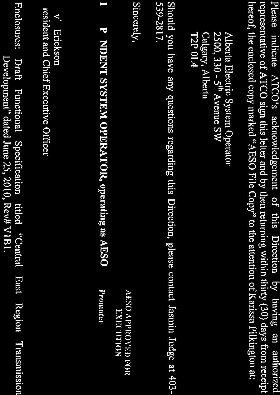
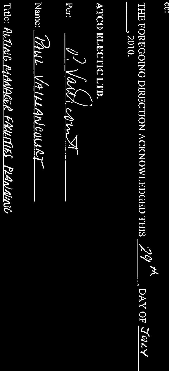
20 REVISION HISTORY Rev. # Description Author Date V1B1 Initial Issue Henry Ng June 25, 2010 V1B2 Second Issue Henry Ng August 12, 2010 R1 Final Issue Henry Ng October 5, 2010 R2 Added critical development in section 4.1 Henry Ng March 18, 2011 File No. RP (ATCO) R2 AESO Functional Specification Page 2 of 66
21 TABLE OF CONTENTS 1. INTRODUCTION DATA DISCLAIMER TFO SERVICE PROPOSAL AND ESTIMATE PROJECT OVERVIEW Proposed Facility Additions Stage I development: Stage II development: Future / Ultimate Development SCOPE OF WORK General Standards Substation Equipment Specifications ATCO Scope of Work (Stage I) General Requirements Conversion of St. Paul 707S and Willingdon 711S Transmission Lines St. Paul 707S Substation (Appendix 7.3.3) Watt Lake 956S (Appendix ) Willingdon 711S Substation (Appendix 7.3.5) Bonnyville 700S Substation (Appendix 7.3.1) Whitby Lake 819S Substation (Appendix 7.3.7) Cold Lake Area Reinforcements Part I Transmission Lines Bourque 970S Substation (Appendix ) Mahihkan 837S Substation (Appendix 7.3.9) Cold Lake Area Reinforcements Part II Transmission Lines Bonnyville 700S Substation (Appendix 7.3.1) Cold Lake Area Reinforcements Part III Transmission Lines Leming Lake 715S Substation File No. RP (ATCO) R2 AESO Functional Specification Page 3 of 66
22 Wolf Lake 822S Substation Marguerite Lake 826S Substation (Appendix 7.3.8) Provost and Lloydminster Areas Line Re-builds Transmission Lines Lloydminster 716S Substation Line Clearance Mitigations Transmission Lines Battle River and Lloydminster Areas Reinforcements Transmission Lines Kitscoty 705S Substation (Appendix 7.3.2) Hill 751S Substation Heisler 764S Substation (Appendix 7.3.6) Vermilion 710S Substation (Appendix 7.3.4) Vermilion Area Voltage Support Vermilion 710S Substation (Appendix 7.3.4) ATCO Scope of Work (Stage II) General Requirements L50 Re-build Transmission Lines Battle River 757S Substation Cold Lake Area Additions (Year 2017) Transmission Lines Marguerite Lake 826S Substation (Appendix 7.3.8) Bourque 970S Substation (Appendix ) TRANSMISSION SYSTEM OPERATING CHARACTERISTICS Short Circuit Current Levels Insulation Levels Operational Constraints APPENDICES Central East Region Transmission System - Existing Central East Region Transmission System - Proposed Developments Substation Single Line Diagrams Bonnyville 700S Substation Proposed Development File No. RP (ATCO) R2 AESO Functional Specification Page 4 of 66
23 7.3.2 Kitscoty 705SSubstation Proposed Development St. Paul 707S Substation Proposed Development Vermilion 710S Substation Proposed Development Willingdon 711S Substation Proposed Development Heisler 764S Substation Proposed Development Whitby Lake 819S Substation Proposed Development Marguerite Lake 826S Substation Proposed Development Mahihkan 837S Substation Proposed Development Watt Lake 956S Substation Proposed Development Bourque 970S Substation Proposed Development Bourque 970S Substation Proposed 2017 Development Energy Data Requirements SCADA Point Requirements Bonnyville 700S Substation Kitscoty 705S Substation St. Paul 707S Substation Vermilion 710S Substation Heisler 764S Substation Whitby Lake 819S Substation Marguerite Lake 826S Substation Mahihkan 837S Substation Watt Lake 956S Substation Bourque 970S Substation Bourque 970S Substation Development SCADA Data Requirements File No. RP (ATCO) R2 AESO Functional Specification Page 5 of 66
24 1. INTRODUCTION This Alberta Electric System Operator ( AESO ) Functional Specification ( the Specification ) is intended to provide functional direction to the Transmission Facilities Owners ( TFOs ), as well as a party who has made an application to the AESO for system access ( Customer ) pursuant to the AESO s tariff ( ISO Tariff ), for the development of new or modified transmission facilities for interconnection with the Alberta Transmission System ( ATS ). The Specification also serves to delineate the work to be completed by various parties involved in the development of such facilities, provide reference to applicable standards and guidelines to be applied in the design of such facilities, outline the electrical environment in which such facilities will operate, and provide reference to the applicable rules and templates for the format required for proposals and estimates to be submitted by the TFO s. 2. DATA DISCLAIMER This Specification should not be used, nor relied upon, by any Customer, TFO, or other party for any purpose other than that stated in section 1. The information presented in this Specification is based on data provided by third parties to the AESO. These third parties have made no guarantees, expressed or implied, with respect to the completeness or accuracy of the provided data. AESO has taken reasonable steps to verify this data where possible and believes it to be accurate. 3. TFO SERVICE PROPOSAL AND ESTIMATE The TFO s Service Proposal and Estimate must be submitted and prepared in accordance with the terms of ISO Rule 9.1, section Obligation to Provide Service Proposal and Service Proposal Estimate The final scope of work and any TFO requested exceptions from the scope of work must be approved by the AESO and no work is to be commenced until a Direction has been provided in accordance with ISO Rule 9.1, Section b). 4. PROJECT OVERVIEW 4.1 PROPOSED FACILITY ADDITIONS The project outlined in this document includes the transmission developments required to be carried out by ATCO within the Central East Region, the proposed developments as outlined in the Need Application are as follows: Stage I development: 1. Bonnyville and St. Paul Areas: a. Re-build and relocate existing 72 kv Willingdon 711S substation, convert to 144 kv and connect it via tapping nearby 144 kv line 7L92 line. The new File No. RP (ATCO) R2 AESO Functional Specification Page 6 of 66
25 substation shall be designated as Watt Lake 956S. 72kV supply and transformer will be retained for backup supply to town load. b. Convert existing 72 kv St. Paul 707S substation to 144 kv and connect it to 144 kv line 7L70 using an in and out configuration. Demobilize all 72 kv equipment at St. Paul 707S and install two 144/25 kv low noise transformers at this site. c. Demobilize (i.e. this equipment will be removed from this site for potential future use at other sites) all 72 kv equipment at Bonnyville 700S including the 144/72kV tie transformer and the two 72/25 kv load transformers. Install a new 144/25 kv load transformer at Bonnyville. d. Restore the capacity of 144 kv line 7L53 (from Bonnyville 700S to Irish Creek 706S) and 7L117 (from Irish Creek 706S to Vermilion 710S) to its full thermal conductor rating by mitigating line clearance issues. 2. Cold Lake Planning Area: a. Build a new 144 kv switching station (named as Bourque 970S), with associated set of breakers, near the existing Mahihkan 837S. b. Build a new double circuit 240 kv, one side strung, from Bourque 970S to Bonnyville 700S using 2x795 MCM ACSR conductors per phase. This line will be initially operated at 144 kv, and be designated as 7L146. c. Build a new 144 kv double circuit line from Bourque 970S to Mahihkan 837S using 1x477 MCM ACSR conductor per phase, lines to be designated as 7L157 and 7L160. d. Re-build 144 kv line 7L74 from Wolf Lake 822S and re-terminate it from Mahihkan 837S to Bourque 970S using 1x795 MCM ACSR conductor per phase. e. Re-build 144 kv line 7L83 from Leming Lake 715S and re-terminate it from Mahihkan 837S to Bourque 970S using 1x477 MCM ACSR conductor per phase. f. Re-build 144 kv line 7L87 from Marguerite Lake 826S to Wolf Lake 822S using 1x795 MCM ACSR conductor per phase. g. Remove existing thermal protection schemes in the Cold Lake area. h. Salvage the SVC equipment and associated building at Bonnyville 700S prior to new 144kV bay development for 7L Provost Planning Area: a. Re-build 144 kv line 7L749 from Lloydminster 716S to ownership boundary using 1x477 MCM ACSR conductor per phase. 4. Lloydminster and Battle River Planning Areas: File No. RP (ATCO) R2 AESO Functional Specification Page 7 of 66
26 a. Restore capacity of the 144 kv lines 7L14 (from Vermilion 710S to Hill 751S) and 7L701 (from Battle River 757S to Strome 223S) to their respective full thermal conductor rating by mitigating line clearance issues. b. Upgrade the existing 72 kv Heisler 764S and Kitscoty 705S substations to 144 kv by connecting them to nearby 7L701 and 7L14 lines, respectively. Install 144/72/25 kv tie transformer that is relocated from Vermilion 710S. c. Salvage 72 kv line 6L06 from Kitscoty 705S to Vermilion 710S and demobilize all 72 kv equipment at Vermilion 710S. d. Install a new 144 kv 25 MVAr capacitor bank at Vermilion 710S. e. Install a new 144/25 kv transformer at Vermilion 710S. The proposed ISD for stage I development is Fourth Quarter The intention is that all components of the Stage I development be completed by Q In the event the Q in-service date cannot be met for all the Stage I components and in order to facilitate connection projects and address operational issues, the following Stage I components are identified as priority development: 1. Cold Lake Planning Area: Build a new 144 kv switching station (named as Bourque 970S) near the existing Mahihkan 837S. Build a new 240 kv line on double circuit towers, one side strung from Bourque 970S to Bonnyville 700S using 2x795 MCM ACSR conductor. This line will be initially operated at 144 kv level Build a new 144 kv double circuit line from Bourque 970S to Mahihkan 837S using 477 MCM ACSR conductors. Re-build 144 kv 7L83 line from Leming Lake 715S and re-terminate it from Mahihkan to Bourque substation using 1x795 MCM ACSR conductor. 2. St. Paul Area: Re-build the existing 72 kv Willingdon 711S substation to 144 kv (named as Watt Lake) and connect it via tapping nearby 144 kv line 7L92 line. 3. Lloydminster area Area: Restore the capacity of the 144 kv lines 7L53 and 7L117 (from Vermilion 710S to Bonnyville 700S) by line clearance mitigation measures. Restore the capacity of the 144 kv lines 7L14 (from Vermilion 710S to Hill 751S) by line clearance mitigation measures. File No. RP (ATCO) R2 AESO Functional Specification Page 8 of 66
27 Install a new 144 kv 25 MVAr capacitor bank at Vermilion 710S Stage II development: 1. Re-build the aging 138/144 kv 7L50 line from Battle River 757S to Buffalo Creek 526S using 1x477 MCM ACSR conductor per phase. 2. Build a new double circuit 240 kv line with one side strung from Bourque 970S to Marguerite Lake 826S using 2x795 MCM ACSR conductors per phase. This line will be initially operated at 144 kv. The proposed ISD for stage II development is Fourth Quarter FUTURE / ULTIMATE DEVELOPMENT Refer to the AESO Long-term Transmission System Plan for possible future development in Central East Region. File No. RP (ATCO) R2 AESO Functional Specification Page 9 of 66
28 5. SCOPE OF WORK 5.1 GENERAL TFOs and Customers are accountable for all engineering, design, land or land-use acquisition, siting, applicable regulatory approvals and permits, material procurement, construction, commissioning, and associated permitting requirements for their facilities. TFOs and customers shall coordinate as required on all design details (e.g., protection & control, grounding, insulation, point of interconnection, site layout, power quality, etc.) and develop Joint Operating Procedures and/or Interconnection Agreements as required to ensure that interconnected facilities are operated safely and reliably. In accordance with ISO Rule 9.1 the TFO s must provide, as a minimum, project reporting as per Section Project Reporting by Designated TFO s and project material and labor procurement as per Section Project Procurement. All new or modified facilities will be adequately inspected by their owner or qualified representative to ensure compliance with this functional specification. All final design and as-built facility information shall be supplied in the format and content as required by the AESO for purposes of updating and maintaining the AESO s technical records and system models. This information shall be submitted under signature of a registered Professional Engineer in Alberta who is representing the facility owner and is assuming responsibility for the preparation and accuracy of the submission. The AESO accepts no responsibility for facilities designed by or for any third party, or installed on a third parties behalf, to accomplish the interconnection. The facility owners shall ensure that their facilities have been inspected and declared safe for operation prior to energization. No facilities are to be energized until an Energization Certificate has been issued by the AESO. 5.2 STANDARDS All work undertaken by TFOs and customers must be designed, constructed, and operated to meet the functional requirements of the Specification and all applicable standards, guidelines, codes and regulations governing such installations including, but not limited those listed below. All AESO documentation can be found on the AESO website ( AESO Operating Policies and Procedures Independent System Operator (ISO) Rules AESO Alberta Reliability Standards AESO Measurement System Standard Rev 1 (dated September 18, 2007) AESO Generation and Load Interconnection Standard (dated September 19, 2006) Technical Requirements (Part 3) for Connecting Transmission Facilities (dated December 29, 1999) File No. RP (ATCO) R2 AESO Functional Specification Page 10 of 66
29 AESO Alberta Interconnected Electric System Protection Standard (dated December 1, 2004) AESO Operational Voice Communication Standard (dated September ) AESO SCADA Standard (dated September 6, 2005) AESO Transmission Modeling Data Requirements ( dated April 29, 2003) AESO PMU Requirements Version 2.0 (dated July 6, 2005) AESO Wind Power Technical Requirements (dated November 15, 2004) 5.3 SUBSTATION EQUIPMENT SPECIFICATIONS All transmission equipment must meet the following minimum specifications: Temperature rating of -50ºC for all outdoor equipment. Equipment maximum and minimum voltage ratings as indicated in Table 1 Minimum continuous equipment current ratings as indicated in Table 2 Maximum Fault Level 31.5kA at 144 kv and 40kA at 240kV Table 1: Equipment Maximum and Minimum Voltages (kv) Area 72 kv 144 kv 240 kv 500 kv Minimum Maximum Note: Typical transmission operating voltages can be found in OPP #702. Table 2: Minimum Continuous Equipment Current Ratings (A) Component 69/72 kv 138/144 kv 240 kv Main Bus Cross Bus Feeder Main bus includes all sections of ring bus scheme and single bus of simple bus scheme. 2. Cross bus includes diameter sections of breaker and a half or breaker and a third schemes. 3. Feeder includes all equipment from the connection to the low voltage bus to the riser pole. File No. RP (ATCO) R2 AESO Functional Specification Page 11 of 66
30 5.4 ATCO SCOPE OF WORK (STAGE I) General Requirements Carry out transmission line routing, insulation coordination and protection coordination studies. Install station terminal control (e.g. 3 pole tripping and re-closing provisions), supervisory control and data acquisition facilities. Undertake all required grounding studies, testing and mitigation to ensure the facilities are safe. Ensure project safety is appropriately managed from design through construction. Carry out all site preparation, fencing, foundations, grounding, support structures, termination structures, cabling, bus work, station service, control building, protection, controls, SCADA equipment, etc. as required to complete the additions and/or modifications outlined in this Functional Specification Conversion of St. Paul 707S and Willingdon 711S Transmission Lines o Build approximately 5km in length of MCM ACSR single circuit from 7L92 tap off point to Watt Lake 956S (new Willingdon substation). The tap off point is approximately midway between Vegreville 709S and Vilna 777S. o Facility code of the tapped line is 7LA92. o Build approximately 32km in length of MCM ACSR double circuit from 7L70 connection point to St. Paul 707S. (7L70 will be split approximately midway between Bonnyville and Whitby Lake.) o Re-number facility code of the 144 kv line between St. Paul 707S and Whitby Lake 819S as 7L139. o Retain facility code of the 144 kv line between St. Paul 707S and Bonnyville 700S as 7L70. o Retain existing 72kV line 6L79 at Vegreville 709S and Watt Lake 956S (new Willingdon substation) ends. This line will serve as back up supply from Vegreville 709S. o Disconnect existing 72kV line 6L79 at Willingdon 711S and St. Paul 707S. Disconnect existing 72 kv line 6L82 at St. Paul 707S and Bonnyville 700S. Portion of these lines may be retained for use by ATCO File No. RP (ATCO) R2 AESO Functional Specification Page 12 of 66
31 Distribution due to large amount of distribution line understrung on the existing structures St. Paul 707S Substation (Appendix 7.3.3) o Design, procure, install and commission the following equipment: Expand existing site to allow for 144kV bay development. Two (2)144 kv line breakers c/w three phase sets of CTs and associated ganged manual disconnects. Terminate the new line 7L139 from Whitby Lake 819S. Terminate the new line 7L70 from Bonnyville 700S. Two (2)144 kv transformer breakers c/w associated ganged manual breaker disconnects. One (1) set three phase 144 kv bus PTs. Two (2) 144/25kV 25/33.3/41.6 MVA POD transformers with +5/-15% LTC specified for low noise emission. Two (2) 25kV motor-operated load break switches (one for each transformer) One (1) 25kV bus tie load break switch. Demobilize all 72kV equipment and 25kV voltage regulators 501VR, 502VR and 503VR. All necessary changes including protection changes, apparatus renumbering and associated drawing revisions. o Protection Requirements: Install a set of A and B line protections as required for 7L139 and 7L70 lines at St. Paul 707S substation. Add breaker fail protection as required to the 144 kv circuit breakers associated with 7L139 and 7L70 lines. Install all other required protection and control equipment at St. Paul 707S substation to accommodate the additional equipment as per AESO s Protection standard. o SCADA Requirements: File No. RP (ATCO) R2 AESO Functional Specification Page 13 of 66
32 Addition of status, analog, control and alarm information at St. Paul 707S, which is to be communicated to TFO s control centre and the AESO control centre for real time operations. o Telecommunication Requirements: Install telecommunication equipment as required at St. Paul 707S for protection signaling and SCADA communication Watt Lake 956S (Appendix ) o Design, procure, install and commission the following equipment: Relocate existing Willingdon 711S substation and convert to 144kV. One (1) 144 kv transformer breaker c/w associated ganged manual disconnects. One (1) set three phase 144 kv bus PTs. One (1) 144/25kV 15/20/25 MVA POD transformer with +5/-15% LTC. One (1) 144 kv ganged manual line disconnect. Terminate the new line 7LA92 which tapped on to 7L92 line at approximately the mid point between Whitby Lake 819S and Vegreville 709S. One (1) 25kV motor-operated load break switch. Two (2) 25kV breakers and associated switches. Install the following equipment to facilitate a back up supply from Vegreville 709S: One (1) 72kV circuit breaker c/c associated ganged manual disconnects. Two (2) 72/25 kv 6/8MVA transformers. Two (2) 25 kv voltage regulators. Two (2) 25 kv breakers with associated switches. All necessary changes including protection changes, apparatus renumbering and associated drawing revisions. o Protection Requirements: File No. RP (ATCO) R2 AESO Functional Specification Page 14 of 66
33 Install all required protection and control equipment at Watt Lake 956S substation to accommodate the additional equipment as per AESO s Protection standard. o SCADA Requirements: Addition of status, analog, control and alarm information at Watt Lake 956S, which is to be communicated to TFO s control centre and the AESO control centre for real time operations. o Telecommunication Requirements: Install telecommunication equipment as required at Watt Lake 956S for protection signaling and SCADA communication Willingdon 711S Substation (Appendix 7.3.5) o Demobilize 6L79D4 and existing two 25kV bays. o Re-install 72kV breaker, transformer and voltage regulator at Watt Lake 956S as required to retain back-up supply for the town load Bonnyville 700S Substation (Appendix 7.3.1) o Design, procure, install and commission the following equipment: One (1) 144 kv transformer breaker c/w and associated ganged manual disconnects. Two (2) new 25kV breakers c/w associated CTs and disconnects to replace 5L17 and 5L47 bays to line up with the new POD transformer location. One (1) 144/25kV 25/33.3/41.6 MVA POD transformer with +5/- 15% LTC. Two (2) 25kV motor-operated load break switches (one for the new transformer, one to replace the existing transformer LS switch) One (1) 25kV bus tie load break switch. Demobilize existing 25kV 5L17 and 5L47 bays. Demobilize all 72kV equipment and the 144/72kV tie transformer. Retain line number 7L70, change destination substation from Whitby Lake 819S to St. Paul 707S after completion of this project. All necessary changes including protection changes, apparatus renumbering and associated drawing revisions. File No. RP (ATCO) R2 AESO Functional Specification Page 15 of 66
34 o Protection Requirements: Install all required protection and control equipment at Bonnyville 700S substation to accommodate the additional equipment as per AESO s Protection standard. o SCADA Requirements: Addition of status, analog, control and alarm information at Bonnyville 700S, which is to be communicated to TFO s control centre and the AESO control centre for real time operations. o Telecommunication Requirements: Install telecommunication equipment as required at Bonnyville 700S for protection signaling and SCADA communication. Note: Further Development is proposed for Bonnyville 700S under Cold Lake Area Reinforcement Part II. Refer to section for details Whitby Lake 819S Substation (Appendix 7.3.7) o Design, procure, install and commission the following equipment: One (1) 144 kv line breaker c/w three phase sets of CTs and associated ganged manual breaker/line disconnects. Salvage auto-sectionalizing scheme and associated PTs. Renumber line 7L70 to 7L139, change destination substation from Bonnyville 700S to St. Paul 707S after completion of this project. All necessary changes including protection changes, apparatus renumbering and associated drawing revisions. o Protection Requirements: Install a set of A and B line protections as required for 7L139 line at Whitby Lake 819S substation. Add breaker fail protection as required to the 144 kv circuit breaker associated with 7L139 line. Install all other required protection and control equipment at Whitby Lake 819S substation to accommodate the re-built line as per AESO s Protection standard. o SCADA Requirements: File No. RP (ATCO) R2 AESO Functional Specification Page 16 of 66
35 Addition of status, analog, control and alarm information at Whitby Lake 819S, which is to be communicated to TFO s control centre and the AESO control centre for real time operations. o Telecommunication Requirements: Install telecommunication equipment as required at Whitby Lake 819S for protection signaling and SCADA communication Cold Lake Area Reinforcements Part I Transmission Lines o Build approximately 2km of 1x477 MCM ACSR double circuit lines 7L157 and 7L160 from Mahihkan 837S to the new Bourque 970S substation. o OPGW to be installed in the shield wire to accommodate line differential protection on these short lines Bourque 970S Substation (Appendix ) Build a new switching station designated as Bourque 970S in the vicinity of existing Mahihkan 837S substation. The switching station shall initially consist of the 144 kv switchyard with a breaker and one-third bus configuration. o Major equipment in the new substation shall include the following: Five (5) 144 kv breakers c/w isolation switches and CTs in a breaker and one third arrangement. Seven (7) sets of three phase 144 kv PTs (One (1) set for each of the five (5) line terminals and one (1) set for each of the 144kV buses). Five (5) 144 kv motorized line disconnects. Terminate the new lines 7L157 & 7L160 from Mahihkan 837S. Terminate the re-built line 7L83 from Leming Lake 715S. Terminate the re-built line 7L74 from Wolf Lake 822S. Terminate the new line 7L146 from Bonnyville 700S. All site preparation, fencing, foundations, grounding, support structures, termination structures, cabling, bus work, station service, control building, protection, controls, SCADA equipment & File No. RP (ATCO) R2 AESO Functional Specification Page 17 of 66
36 Control Center data mapping and verifications, etc. as required for this new substation. Allow sufficient land for the substation ultimate configuration of possible 240kV tie transformer and line with a one and one-half breaker arrangement on the 240kV section and expansion capabilities on the 144 kv breaker and one-third arrangement. o Protection Requirements: Install a set of A and B line protections as required for 7L157, 7L160, 7L83, 7L74 and 7L146 lines at Bourque 970S substation. Add breaker fail protection as required to the 144 kv circuit breakers associated with 7L157, 7L160, 7L83, 7L74 and 7L146 lines. Install all other required protection and control equipment at Bourque 970S substation to accommodate the re-built lines as per AESO s Protection standard. o SCADA Requirements: Addition of status, analog, control and alarm information at Bourque 970S, which is to be communicated to TFO s control centre and the AESO control centre for real time operations. o Telecommunication Requirements: Install fibre optic telecommunication equipment as required at Bourque 970S for protection signaling and SCADA communication. Note: Further Development is proposed for Bourque 970S under Cold Lake Area Additions (Year 2017). Refer to section for details Mahihkan 837S Substation (Appendix 7.3.9) o Design, procure, install and commission the following equipment: Remove line 7L83 and terminate the new line 7L157 from Bourque 970S. Remove line 7L74 and terminate the new line 7L160 from Bourque 970S. All necessary changes including protection changes, apparatus renumbering and associated drawing revisions. o Protection Requirements: Install a set of A and B line protections as required for 7L157 and 7L160 lines at Mahihkan 837S substation. File No. RP (ATCO) R2 AESO Functional Specification Page 18 of 66
37 Add breaker fail protection as required to the 144 kv circuit breakers associated with 7L157 and 7L160 lines. Install all other required protection and control equipment at Mahihkan 837S substation to accommodate the new lines as per AESO s Protection standard. o SCADA Requirements: Addition of status, analog, control and alarm information at Mahihkan 837S, which is to be communicated to TFO s control centre and the AESO control centre for real time operations. o Telecommunication Requirements: Install fibre optic telecommunication equipment as required at Mahihkan 837S for protection signaling and SCADA communication Cold Lake Area Reinforcements Part II Transmission Lines o Build approximately 50km of 2x795 MCM ACSR double circuit line with only one side strung from Bonnyville 700S to the new Bourque 970S substation. The line shall be built to 240kV standard and initially energized at 144 kv. The new line shall be designated as 7L146. o OPGW to be installed in the shield wires Bonnyville 700S Substation (Appendix 7.3.1) Design, procure, install and commission the following equipment: o One (1) 144 kv line breaker c/w three phase sets of CTs and associated ganged manual disconnects. o Relocate 7L24 into the new bay. o Terminate the new line 7L146 from Bourque 970S into existing 7L24 bay (after 7L24 relocation). o Salvage existing SVC and SVC building including breaker 700, 703T, 700D3 and all 6.6kV and associated equipment. o All necessary changes including protection changes, apparatus renumbering and associated drawing revisions. File No. RP (ATCO) R2 AESO Functional Specification Page 19 of 66
38 o Protection Requirements: Install a set of A and B line protections as required for 7L24 and 7L146 lines at Bonnyville 700S substation. Add breaker fail protection as required to the 144 kv circuit breakers associated with 7L24 and 7L146 lines. Install all other required protection and control equipment at Bonnyville 700S substation to accommodate the new and re-located lines as per AESO s Protection standard. o SCADA Requirements: Addition of status, analog, control and alarm information at Bonnyville 700S, which is to be communicated to TFO s control centre and the AESO control centre for real time operations. o Telecommunication Requirements: Install fibre optic telecommunication equipment as required at Bonnyville 700S for protection signaling and SCADA communication Cold Lake Area Reinforcements Part III Transmission Lines o Re-build existing 144 kv line 7L87 on new right of way ( ROW ), approximately 15 km in length, from Marguerite Lake 826S substation to Wolf Lake 822S substation with 1x795 MCM ACSR conductor per phase. Install OPGW in the shield wire for existing tele-protection scheme. Salvage existing 7L87 after the new line is in service. o Re-build existing 144 kv line 7L74 on new ROW, approximately 20 km in length, from Bourque 970S substation to Wolf Lake 822S substation with 1x795 MCM ACSR conductor per phase. Install Dual OPGW in the shield wires for existing tele-protection scheme. Salvage existing 7L74 after the new line is in service. o Re-build existing 144 kv line 7L83, approximately 10 km in length, from Bourque 970S substation to Leming Lake 715S substation with 1x477 MCM ACSR conductor per phase on a new ROW. Install OPGW in the shield wire for existing tele-protection scheme. Salvage existing 7L83 line Leming Lake 715S Substation o Design, procure, install and commission the following equipment: File No. RP (ATCO) R2 AESO Functional Specification Page 20 of 66
39 Remove existing line 7L83 and terminate the re-built line 7L83 (no change in facility code) from Bourque 970S. All necessary changes including protection changes and associated drawing revisions. Salvage the SEL-79 relay on 7L66 and thermal protection scheme. o Protection Requirements: Install a set of A and B line protections as required for 7L83 line at Leming Lake 715S substation. Add breaker fail protection as required to the 144 kv circuit breaker associated with 7L83 line. Install all other required protection and control equipment at Leming Lake 715S substation to accommodate the re-built line as per AESO s Protection standard. o SCADA Requirements: Addition of status, analog, control and alarm information at Leming Lake 715S, which is to be communicated to TFO s control centre and the AESO control centre for real time operations. o Telecommunication Requirements: Install fibre optic telecommunication equipment as required at Leming Lake 715S for protection signaling and SCADA communication Wolf Lake 822S Substation o Design, procure, install and commission the following equipment: Remove existing line 7L74 and terminate the re-built line 7L74 (no change in facility code) from Bourque 970S. Remove existing line 7L87 and terminate the re-built line 7L87 (no change in facility code) from Marguerite Lake 826S. All necessary changes including protection changes and associated drawing revisions. o Protection Requirements: Install a set of A and B line protections as required for 7L74 and 7L87 lines at Wolf Lake 822S substation. Add breaker fail protection as required to the 144 kv circuit breakers associated with 7L74 and 7L87 lines. File No. RP (ATCO) R2 AESO Functional Specification Page 21 of 66
40 Install all other required protection and control equipment at Wolf Lake 822S substation to accommodate the re-built lines as per AESO s Protection standard. o SCADA Requirements: Addition of status, analog, control and alarm information at Wolf Lake 822S, which is to be communicated to TFO s control centre and the AESO control centre for real time operations. o Telecommunication Requirements: Install fibre optic telecommunication equipment as required at Wolf Lake 822S for protection signaling and SCADA communication Marguerite Lake 826S Substation (Appendix 7.3.8) o Design, procure, install and commission the following equipment: Remove existing line 7L87 and terminate the re-built line 7L87 (no change in facility code) from Wolf Lake 822S. All necessary changes including protection changes, apparatus renumbering and associated drawing revisions. Salvage the SEL-79 relay on 7L89 and thermal protection scheme. Remove the SEL-2100 relay and thermal protection schemes for 7L89 and 7L66 sending signal to ESSO Mahkeses as well as AEC at Foster Creek. o Protection Requirements: Install a set of A and B line protections as required for 7L87 line at Marguerite Lake 826S substation. Add breaker fail protection as required to the 144 kv circuit breaker associated with 7L87 line. Install all other required protection and control equipment at Marguerite Lake 826S substation to accommodate the re-built line as per AESO s Protection standard. o SCADA Requirements: Addition of status, analog, control and alarm information at Marguerite Lake 826S, which is to be communicated to TFO s control centre and the AESO control centre for real time operations. o Telecommunication Requirements: File No. RP (ATCO) R2 AESO Functional Specification Page 22 of 66
41 Install fibre optic telecommunication equipment as required at Marguerite Lake 826S for protection signaling and SCADA communication. Note: Further Development is proposed for Marguerite Lake 826S under Cold Lake Area Additions (Year 2017). Refer to section for details Provost and Lloydminster Areas Line Re-builds Transmission Lines o Re-build existing 144 kv line 7L749, approximately 47 km in length, from Lloydminster 716S substation to AltaLink s service boundary, with 1x477 MCM ACSR conductor per phase. Install OPGW in the shield wire for existing tele-protection scheme. o ATCO shall coordinate with AltaLink on construction of the remaining portion of the line to Edgerton 899S substation Lloydminster 716S Substation o Design, procure, install and commission the following equipment: Remove existing line 7L749 and terminate the re-built line 7L749 (no change in facility code) from Edgerton 899S. All necessary changes including protection changes, apparatus renumbering and associated drawing revisions. o Protection Requirements: Install a set of A and B line protections as required for 7L749 line at Lloydminster 716S substation. Add breaker fail protection as required to the 144 kv circuit breaker associated with 7L749 line. Install all other required protection and control equipment at Lloydminster 716S substation to accommodate the re-built line as per AESO s Protection standard. ATCO shall coordinate with AltaLink on protection setting changes at Edgerton 899S substation. o SCADA Requirements: Addition of status, analog, control and alarm information at Lloydminster 716S, which is to be communicated to TFO s control centre and the AESO control centre for real time operations. o Telecommunication Requirements: File No. RP (ATCO) R2 AESO Functional Specification Page 23 of 66
42 Install fibre optic telecommunication equipment as required at Lloydminster 716S for protection signaling and SCADA communication Line Clearance Mitigations Transmission Lines o Restore ratings of the 144 kv lines 7L14, 7L701, 7L117 and 7L53 to their respective full conductor thermal capacities by mitigating line clearance issues Battle River and Lloydminster Areas Reinforcements Transmission Lines o Build a new double circuit 144 kv line extension, approximately 10 km in length, from Kitscoty 705S to the existing 7L14 line, with 1x266.8 MCM ACSR conductor per phase. Split the existing 7L14 to accommodate tiein of the double circuit line from Kitscoty 705S. Install a 144 kv manual line disconnect switch, operated as normally open, at the split point. o Build a new single circuit 144 kv line, approximately 3 km in length, from Heisler 764S to tap on existing 7L701 line, with 1x397.5 MCM ACSR conductor per phase. Install three (3) 144 kv manual line load break switches at the tap point. The line section from Heisler 764S to the tap point shall be re-numbered as 7LA701. o Salvage the 72kV line 6L06 from Kitscoty 705S to Vermilion 710S Kitscoty 705S Substation (Appendix 7.3.2) o Design, procure, install and commission the following equipment: Expand substation as required to facilitate new equipment. Install new control building and new control panel for the substation. One (1)144 kv transformer breaker c/w associated ganged manual bus disconnects. One (1) 144 kv manual disconnect for line bypass. Terminate both 144 kv line sections of 7L14 from Vermilion 710S and from Hill 751S (to accommodate sectionalize motorized switches at Kitscoty). File No. RP (ATCO) R2 AESO Functional Specification Page 24 of 66
43 Two (2) 144 kv line motorized disconnect switches. One (1) set of three phase 144 kv bus PTs. Two (2) sets of 144 kv line PTs. One (1) 144/25kV 10/13/16.6 MVA POD transformer (re-located from Heisler 704S). One (1) 25 kv voltage regulator (re-located from Heisler 704S). One (1) 25kV motor-operated load break switch. Two (2) 25kV breaker bays and re-connect existing 25kV lines. Retain existing 72/25kV transformer as back up supply for town load. All necessary changes including protection changes, apparatus renumbering and associated drawing revisions. o Protection Requirements: Install a set of A and B line protections as required for 7L14 and 7L130 lines at Kitscoty 705S substation. Add breaker fail protection as required to the 144 kv circuit breakers associated with 7L14 and 7L130 lines. Install all other required protection and control equipment at Kitscoty 705S substation to accommodate the additional equipment as per AESO s Protection standard. o SCADA Requirements: Addition of status, analog, control and alarm information at Kitscoty 705S, which is to be communicated to TFO s control centre and the AESO control centre for real time operations. o Telecommunication Requirements: Install fibre optic telecommunication equipment as required at Kitscoty 705S for protection signaling and SCADA communication Hill 751S Substation Design, procure, install and commission the following equipment: o All necessary changes including protection changes, apparatus renumbering and associated drawing revisions. File No. RP (ATCO) R2 AESO Functional Specification Page 25 of 66
44 Heisler 764S Substation (Appendix 7.3.6) o Design, procure, install and commission the following equipment: Expand substation as required to facilitate new equipment. Install new control building and new control panel for the substation. One (1) 144 kv transformer breaker c/w associated ganged manual breaker disconnects. One (1) 72/25kV 6/8 MVA POD transformer (from maintenance spares). One (1) 144kV line disconnect switch. Terminate 144 kv line 7LA701. One (1) set of three phase144 kv bus PTs. One (1) /25kV 25/33 MVA POD transformer that is relocated (after refurbishment) from Vermilion 710S. One (1) 72kV transformer breaker associated ganged manual disconnects. One (1) 72kV motorized disconnect switch. One (1) set of 72kV three phase bus PTs. One (1) 25 kv voltage regulator that is relocated from Vermilion 710S. Two (2) 25kV motor-operated load break switches. Remove existing 72/25 kv transformer and voltage regulator and relocate it to Kitscoty 705S. Replace with 6/8/10 MVA transformer and regulator from maintenance spare. All necessary changes including protection changes, apparatus renumbering and associated drawing revisions. o Protection Requirements: Review and revise line protection settings as required at Strome 223S and Battle River 757S for the additional equipment at Heisler 764S substation. File No. RP (ATCO) R2 AESO Functional Specification Page 26 of 66
45 Install all other required protection and control equipment at Heisler 764S substation to accommodate the additional equipment as per AESO s Protection standard. o SCADA Requirements: Addition of status, analog, control and alarm information at Heisler 764S, which is to be communicated to TFO s control centre and the AESO control centre for real time operations. o Telecommunication Requirements: Install telecommunication equipment as required at Heisler 764S for protection signaling and SCADA communication Vermilion 710S Substation (Appendix 7.3.4) o Design, procure, install and commission the following equipment: One (1) 144 kv transformer breaker c/w associated ganged manual disconnect (project team to determine whether existing 706A switch could be re-used). One (1) 144/25kV 25/33.3/41.6 MVA POD transformer with +5/- 15% LTC. One (1) 25kV motorized load break switch. Demobilize/Salvage 701TCS and all 72kV equipment. 144/72/25kV tie transformer and 25kV regulator to be relocated to Heisler 746S. All necessary changes including protection changes, apparatus renumbering and associated drawing revisions. o Protection Requirements: Install all required protection and control equipment at Vermilion 710S substation to accommodate the additional equipment as per AESO s Protection standard. o SCADA Requirements: Addition of status, analog, control and alarm information at Vermilion 710S, which is to be communicated to TFO s control centre and the AESO control centre for real time operations Vermilion Area Voltage Support Vermilion 710S Substation (Appendix 7.3.4) File No. RP (ATCO) R2 AESO Functional Specification Page 27 of 66
46 o Design, procure, install and commission the following equipment: One (1) 144 kv 25MVAr un-grounded capacitor bank. One (1) 144 kv circuit breaker with zero crossing control, c/w three phase sets of CTs and associated ganged manual disconnects. All necessary changes including protection changes, apparatus renumbering and associated drawing revisions. o Protection Requirements: Install all required protection and control equipment at Vermilion 710S substation to accommodate the additional equipment as per AESO s Protection standard. o SCADA Requirements: Addition of status, analog, control and alarm information at Vermilion 710S, which is to be communicated to TFO s control centre and the AESO control centre for real time operations. 5.5 ATCO SCOPE OF WORK (STAGE II) General Requirements Carry out transmission line routing, insulation coordination and protection coordination studies. Install station terminal control (e.g. 3 pole tripping and re-closing provisions), supervisory control and data acquisition facilities. Undertake all required grounding studies, testing and mitigation to ensure the facilities are safe. Ensure project safety is appropriately managed from design through construction. Carry out all site preparation, fencing, foundations, grounding, support structures, termination structures, cabling, bus work, station service, control building, protection, controls, SCADA equipment, etc. as required to complete the additions and/or modifications outlined in this Functional Specification L50 Re-build Transmission Lines o Re-build existing 144 kv line 7L50, approximately 160 km in length, from Battle River 757S substation to Buffalo Creek 526S substation with 1x477 MCM ACSR conductor per phase. Install OPGW in the shield wire for existing tele-protection scheme. File No. RP (ATCO) R2 AESO Functional Specification Page 28 of 66
47 o ATCO shall coordinate with AltaLink on termination of the re-built 7L50 to AltaLink s substations Battle River 757S Substation Design, procure, install and commission the following equipment: o Remove existing line 7L50 and terminate the re-built line 7L50 (no change in facility code) from Buffalo Creek 526S. o All necessary changes including protection changes, apparatus renumbering and associated drawing revisions. o Protection Requirements Install teleprotection on 7L50 between Battle River 757S, Jarrow 252S and Buffalo Creek 526S substations to mitigate existing sequential clearance at Jarrow 252S. Review and revise protection settings as required on 7L50 at Battle River 757S, and Vermilion 710S substations. ATCO shall coordinate with AltaLink on protection setting changes at affected substations. o Telecommunication Requirements Install fibre optic telecommunication equipment as required at Battle River 757S substation for protection signaling and SCADA communication Cold Lake Area Additions (Year 2017) Transmission Lines o Build approximately 20km of 2x795 MCM ACSR double circuit line with only one side strung from Bourque 970S substation to Marguerite Lake 826S substation. The line shall be built to 240kV standard and initially energized at 144 kv. The new line shall be designated as 7L163. o OPGW to be installed in the shield wires Marguerite Lake 826S Substation (Appendix 7.3.8) o Design, procure, install and commission the following equipment: One (1) 144 kv line breaker c/w three phase sets of CTs and associated ganged manual breaker disconnects. One (1) 144kV motorized line disconnect switch. File No. RP (ATCO) R2 AESO Functional Specification Page 29 of 66
48 Terminate the new line 7L163 from Bourque 970S. One (1) set of three phase 144kV PTs. One (1) 144kV motorized line disconnect switch. All necessary changes including protection changes, apparatus renumbering and associated drawing revisions. o Protection Requirements: Install a set of A and B line protections as required for 7L163 line at Marguerite Lake 826S substation. Add breaker fail protection as required to the 144 kv circuit breaker associated with 7L163 line. Install all other required protection and control equipment at Marguerite Lake 826S substation to accommodate the new line as per AESO s Protection standard. o SCADA Requirements: Addition of status, analog, control and alarm information at Marguerite Lake 826S, which is to be communicated to TFO s control centre and the AESO control centre for real time operations. o Telecommunication Requirements: Install fibre optic telecommunication equipment as required at Marguerite Lake 826S for protection signaling and SCADA communication Bourque 970S Substation (Appendix ) o Design, procure, install and commission the following equipment: One (1) 144 kv line breaker c/w three phase sets of CTs and associated ganged manual breaker disconnects. One (1) 144kV motorized line disconnect switch. Terminate the new line 7L163 from Marguerite Lake 826S. All necessary changes including protection changes, apparatus renumbering and associated drawing revisions. o Protection Requirements: Install a set of A and B line protections as required for 7L163 line at Bourque 970S substation. Add breaker fail protection as required to the 144 kv circuit breaker associated with 7L163 line. File No. RP (ATCO) R2 AESO Functional Specification Page 30 of 66
49 Install all other required protection and control equipment at Bourque 970S substation to accommodate the new line as per AESO s Protection standard. o SCADA Requirements: Addition of status, analog, control and alarm information at Bourque 970S, which is to be communicated to TFO s control centre and the AESO control centre for real time operations. o Telecommunication Requirements: Install fibre optic telecommunication equipment as required at Bourque 970S for protection signaling and SCADA communication. File No. RP (ATCO) R2 AESO Functional Specification Page 31 of 66
50 6. TRANSMISSION SYSTEM OPERATING CHARACTERISTICS The following sections provide data to outline the electrical environment in which the facilities outlined in the Specification will operate. TFOs and customers shall incorporate these characteristics into their facility designs and operating procedures as deemed appropriate. 6.1 SHORT CIRCUIT CURRENT LEVELS The following short circuit current levels in Tables 3 and 4 have been developed by the AESO based on information provided by Transmission Facility Owners ( TFO s ), Generation Facility Owners ("GFO s") and adjacent operating areas. Available fault current levels will continue to increase as generation, transmission, and system interties are added to the ATS. Although future values have been provided it is the facility owners responsibility to regularly verify the fault levels and review their equipment ratings for adequacy. Any future upgrades are the responsibility of the facility owner. The following assumptions were incorporated into AESO short circuit models: All expected ATS generation is dispatched. All transmission elements are in service. V base = V bus, MVA base = 100 File No. RP (ATCO) R2 AESO Functional Specification Page 32 of 66
51 Table 3: Existing Maximum Short Circuit Current Levels Substation Name and Number Voltage (kv) Pre- Fault Voltage (p.u.)* 3 Phase Fault Current (ka) Positive Sequence Impedance (R 1 + jx 1 ) (p.u.) 1 Phase Fault Current (ka) Zero Sequence Impedance (R 0 + jx 0 ) (p.u.) Briker 880S j j Irish Creek 706S j j Vermilion 710S j j Vermilion 710S ( be salvaged) j j Kitscoty 705S j j Hill 751S j j Hill 751S j j Lloydminster 716S j j Mahkeses 889S j j Wolf Lake 822S j j Foster Creek 877S j j Primrose 859S j j Mahihkan 837S j j Leming Lake 715S j j Marguerite Lake 826S j j Marguerite Lake 826S j j La Corey j j Ethel Lake 717S j j Ethel Lake 717S j j Grande Centre 846S j j Bonnyville 700S j j Bonnyville 700S (to be salvaged) j j IPF Lindberg j j Heisler 764S j j Bigknife Creek 843S j j Mannix Mine 765S j j Battle River 757S bus j j Battle River 757S bus j j Battle River 757S j j Battle River 757S j j Bigfoot 756S j j Whitby Lake 819S j j Vilna 777S j j Willingdon 711S j j Vegreville 709S j j Vegreville 709S j j St. Paul 707S ( be salvaged) j j Paintearth Creek 863S j j Cordel 755S j j File No. RP (ATCO) R2 AESO Functional Specification Page 33 of 66
52 Table 3: Estimated Year 2017 Maximum Short Circuit Current Levels Substation Name & Number Voltage (kv) Pre- Fault Voltage (p.u.)* 3 Phase Fault Current (ka) Positive Sequence Impedance (R 1 + jx 1 ) (p.u.) 1 Phase Fault Current (ka) Zero Sequence Impedance (R 0 + jx 0 ) (p.u.) Briker 880S j j Irish Creek 706S j j Vermilion 710S j j Vermilion tap sub (NEW) j j Kitscoty 705S (NEW) j j Kitscoty 705S j j Hill 751S j j Hill 751S j j Lloydminster 716S j j Mahkeses 889S j j Wolf Lake 822S j j Foster Creek 877S j j Primrose 859S j j Bourque 970S (NEW) j j Mahihkan 837S j j Leming Lake 715S j j Marguerite Lake 826S j j Marguerite Lake 826S j j La Corey j j Ethel Lake 717S j j Ethel Lake 717S j j Grande Centre 846S j j Enb_Bonn (NEW) j j Bonnyville 700S j j IPF Lindberg j j Heisler 764S (NEW) j j Heisler 764S j j Bigknife Creek 843S j j Mannix Mine 765S j j Battle River 757S bus j j Battle River 757S bus j j Battle River 757S j j Battle River 757S j j Bigfoot 756S j j Whitby Lake 819S j j Vilna 777S j j Watt Lake 956S (NEW) j j Willingdon 711S j j Vegreville 709S j j Vegreville 709S j j St. Paul 707S (NEW) j j Paintearth Creek 863S j j Cordel 755S j j File No. RP (ATCO) R2 AESO Functional Specification Page 34 of 66
53 6.2 INSULATION LEVELS Table 6 provides the minimum required Basic Insulation Levels ( BIL ) levels for the ATS. Station equipment with lower BIL levels can be used provided protection and coordination can be maintained with judicious insulation design and use of appropriate surge arresting equipment. For 25 kv circuit breakers where there is a grounded wye transformer and surge arrestors are installed a BIL of 125 kv is acceptable. Table 6: BIL Levels (kv) Nominal Voltage Classification (kv rms) Station Post Insulators and Airbreaks /138 72/ Circuit Breakers Current and Potential Transformers Transformer Windings (Protected by Surge Arresters)) OPERATIONAL CONSTRAINTS No Operational Constraints have been identified at this stage of the project. File No. RP (ATCO) R2 AESO Functional Specification Page 35 of 66


54 7. APPENDICES 7.1 CENTRAL EAST REGION TRANSMISSION SYSTEM - EXISTING File No. RP (ATCO) R2 AESO Functional Specification Page 36 of 66
55 7.2 CENTRAL EAST REGION TRANSMISSION SYSTEM - PROPOSED DEVELOPMENTS Alternative kv from Nilrem to New Vermilion Legend Existing 69/72 kv Existing 138/144 kv Existing 240 kv Rebuilt 138/144 kv New 138/144 kv New 240 kv Salvaged Line Generator Substation Approved Substation Proposed Substation Proposed in Hanna NID Customer Project Foster Creek 877S 7L86 Foster Creek Generation Station 1200S Primrose 859S Notes: Developments reflect 2012 ISD, unless otherwise specified. Clearance mitigations on 7L701, 7L14, and 7L53. 9L37 Marguerite Lake 826S 9L36 Wolf Lake 822S 7L87 7L74 ISD 2017; Energized at 144 kv 7L74 7L35 New Mahihkan MahNo 909S 7L105 Mahihkan 837S 7L83 7L95 Leming Lake 715S Nabiye Mahkeses 889S 7L89 7L91 7L66 Ethel Lake 717S La Corey 721S Energized at 144 kv Cold Lake 7L28 7L89 Grand Centre 846S 7L24 7L24 Whitby Lake 819S 7L70 Bonnyville 700S Vilna 777S Watt Lake 956S (New Willingdon) 6L79 7L92 St. Paul 707S 6L79 May convert to Distribution 6L82 May convert to Distribution 7L53 7L117 Vermilion 710S IPF Lindbergh 969S Irish Creek 706S Kitscoty 6L06 705S 7L14 Lloydminster Bardo 197S 174L North Holden 395S 7L77 Vegreville 709S 7L65 Buffalo Creek 526S 7L129 (7L50) Briker 880S 7L42 Hill 751S 7LB749 7L749 Lloydminster 716S 701L Strome 223S 7L50 61L ISD 2017 Jarrow 252S 704AL Cochin 968S 61AL ISD 2017 Wainwright 7L749 Nevis 766S Heisler 764S Battle River 757S 843S 6L05 9L20 765S 701L 7L702 Sedgewick 137S Cordel 755S 756S 9L27 9L59 7L50 Anderson 801S Battle River Paintearth 863S 702L Hardisty 377S 681L 704L 769L Rosyth 296S Wainwright Tucuman 51S Edgerton 478S 899S Nilrem 574S 703BL Killarney Lake HRT Express 267S 329S 703L Hughenden 213S 953L 9L953/953L 9L948/948L Sunken Lake 221S 703AL 749L Hansman Lake 650S 749L Metiskow 648S 715L Provost 748L Hayter 277S Provost 545S File No. RP (ATCO) R2 AESO Functional Specification Page 37 of 66
56 7.3 SUBSTATION SINGLE LINE DIAGRAMS Bonnyville 700S Substation Proposed Development 5L17 Convert to Distribution (Line number will be reassigned) 605T 6/8 MVA 5L47 72 kv 604T 6/8 MVA 25 kv 701T 144/72kV 25/33.3/41.6 MVA New Bourque 970S 7L146 (Terminated to existing bay previously for 7L24) Grand Centre 7L24 (Relocated from existing bay) Note: Salvage all 6.6kV equipment associated with the SVC which are not shown in this simplified SLD. 25 kv C/S 702T 144/25 kv 15/20/25 MVA SVC 5L83 5L414 Marguerite Lake Upgraded 144 kv bus at St. Paul 707S 7L89 7L70 144/25 kv 25/33.3/41.6 MVA 16.2 MVAr 5L17 5L47 Legend Vermilion via Irish Creek 7L MVAr Circuit Breaker (Manual Operation) Solid Disconnect Switch (Motor Operated) Proposed Addition/ Change Salvaged Equipment Proposed Scope 144 kv 16.8 MVAr (Ungrounded) Bonnyville 700S Central East Region Transmission Development Proposed Stage 1 Configuration 811-SLD-700S File No. RP (ATCO) R2 AESO Functional Specification Page 38 of 66
57 7.3.2 Kitscoty 705SSubstation Proposed Development Vermilion 710S 6L06 Transformer retained as back-up supply Vermilion 710S 6L06 Hill 751S 601T 72/25 kv 6/8 MVA Regulator 25 kv 7L14 N.O. 7L kv 144/25 kv 10/13.3/16.6 MVA Regulator 25 kv Legend Hill 751S Circuit Breaker (Manual Operation) Solid Disconnect Switch (Motor Operated) Proposed Addition/ Change Salvaged Equipment Proposed Scope Kitscoty 705S Central East Region Transmission Development Proposed Stage 1 Configuration 811-SLD-705S File No. RP (ATCO) R2 AESO Functional Specification Page 39 of 66
58 7.3.3 St. Paul 707S Substation Proposed Development 25 kv 25 kv 603T 15/20/25 MVA Convert to Distribution (Line number will be reassigned) 25 kv 601T 6/8 MVA 602T 6/8 MVA 72 kv Convert to Distribution (Line number will be reassigned) 25 kv 25 kv 144/25 kv 25/33.3/41.6 MVA 7L70 7L139 Bonnyville 700S Whitby Lake 819S 144/25 kv 25/33.3/41.6 MVA 144 kv Legend Circuit Breaker (Manual Operation) Solid Disconnect Switch (Motor Operated) Proposed Addition/ Change Salvaged Equipment Proposed Scope St. Paul 707S Central East Region Transmission Development Proposed Stage 1 Configuration 811-SLD-707S File No. RP (ATCO) R2 AESO Functional Specification Page 40 of 66
59 7.3.4 Vermilion 710S Substation Proposed Development 25 kv ** Relocate 701T to Heisler 764S Hill 751S Bonnyville 700S via Irish Creek) 7L14 7L53 701T 144/72/25 kv 25/33 MVA 72 kv 6L06 Kitscoty 705S Vegreville 709S 7L65 144/25 kv 25/33.3/41.6 MVA 25 kv Buffalo Creek 526S 7L MVAr 144 kv Legend Circuit Breaker (Manual Operation) Solid Disconnect Switch (Motor Operated) Proposed Addition/ Change Salvaged Equipment Proposed Scope Vermilion 710S Central East Region Transmission Development Proposed Stage 1 Configuration 811-SLD-710S File No. RP (ATCO) R2 AESO Functional Specification Page 41 of 66
60 7.3.5 Willingdon 711S Substation Proposed Development 6L79 to St. Paul 5L T 6/8 MVA Regulator 25 kv 6L79 to Vergreville 5L42 72 kv 602T 6/8 MVA Regulator Legend Circuit Breaker (Manual Operation) Solid Disconnect Switch (Motor Operated) Proposed Addition/ Change Salvaged Equipment Proposed Scope Willingdon 711S Central East Region Transmission Development Proposed Stage 1 Configuration 811-SLD-711S File No. RP (ATCO) R2 AESO Functional Specification Page 42 of 66
61 7.3.6 Heisler 764S Substation Proposed Development ** Relocate 601T & Regulator to Kitscoty 705S 601T 72/25 kv 10/13.3/16.6 MVA Regulator 6L02 Junction 6L05 $$ 72/25 kv 6/8 MVA $$ Regulator Strome 223S ## Regulator 25 kv 7L kv ## 144/72/25 kv 25/33 MVA 144 kv 7LA701 7L701 $$ --From maintenance spares ## --Relocated from Vermilion 710S Battle River 757S Legend Circuit Breaker (Manual Operation) Solid Disconnect Switch (Motor Operated) Proposed Addition/ Change Salvaged Equipment Proposed Scope Heisler 764S Central East Region Transmission Development Proposed Stage 1 Configuration 811-SLD-764S File No. RP (ATCO) R2 AESO Functional Specification Page 43 of 66
62 7.3.7 Whitby Lake 819S Substation Proposed Development 7L92 Vergerville (via Vilna) 7L794 Lac La Biche 7L139 St. Paul 707S 144 kv Legend Circuit Breaker (Manual Operation) Solid Disconnect Switch (Motor Operated) Proposed Addition/ Change Salvaged Equipment Proposed Scope Whitby Lake 819S Central East Region Transmission Development Proposed Stage 1 Configuration 811-SLD-819S File No. RP (ATCO) R2 AESO Functional Specification Page 44 of 66
63 7.3.8 Marguerite Lake 826S Substation Proposed Development 901T 240/144 kv 120/160/200 MVA Wolf Lake 822S 7L87 Re-build 902T 240/144 kv 120/160/200 MVA 240 kv Network 240 kv Network 144 kv 7L91 7L163 7L kv Leming Lake 715S Bourque 970S Bonnyville 700S Legend Circuit Breaker (Manual Operation) Solid Disconnect Switch (Motor Operated) Proposed Addition/ Change Salvaged Equipment Proposed Scope Marguerite Lake 826S Central East Region Transmission Development Proposed Configuration 811-SLD-826S File No. RP (ATCO) R2 AESO Functional Specification Page 45 of 66
64 7.3.9 Mahihkan 837S Substation Proposed Development Bourque 970S (re-use existing bay) 7L T 22/33.3/41.5 MVA 25 kv Bourque 970S (re-use existing bay) 7L kv MahNo 909S 7L T 25/33/41.6 MVA 144 kv Legend Circuit Breaker (Manual Operation) Solid Disconnect Switch (Motor Operated) Proposed Addition/ Change Salvaged Equipment Proposed Scope Mahihkan 837S Central East Region Transmission Development Proposed Stage 1 Configuration 811-SLD-837S File No. RP (ATCO) R2 AESO Functional Specification Page 46 of 66
65 Watt Lake 956S Substation Proposed Development 7L92 tap point 25 kv 5L kv 144 / 25 kv 15/20/25 MVA 5L T 6/8 MVA Regulator 25 kv 6L79 to Vergreville 72 kv 602T 6/8 MVA Regulator Legend Note: Re-install 72kV breaker, transformer and regulator, salvaged from Willingdon 711S, as required to retain back up supply to the town load. Circuit Breaker (Manual Operation) Solid Disconnect Switch (Motor Operated) Proposed Addition/ Change Salvaged Equipment Proposed Scope Watt Lake 956S (New Willingdon) Central East Region Transmission Development Proposed Stage 1 Configuration 811-SLD-956S File No. RP (ATCO) R2 AESO Functional Specification Page 47 of 66
66 Bourque 970S Substation Proposed Development 144 kv Mahihkan 837S 7L157 Leming Lake 715S 7L83 Bonnyville 700S 7L146 Wolf Lake 822S 7L74 Mahihkan 837S 7L kv Legend Circuit Breaker (Manual Operation) Solid Disconnect Switch (Motor Operated) Proposed Addition/ Change Salvaged Equipment Proposed Scope Bourque 970S Central East Region Transmission Development Proposed Stage 1 Configuration 811-SLD-970S File No. RP (ATCO) R2 AESO Functional Specification Page 48 of 66
67 Bourque 970S Substation Proposed 2017 Development 144 kv Mahihkan 837S 7L157 Marguerite Lake 826S 7L163 Leming Lake 715S 7L83 Bonnyville 700S 7LXXX Wolf Lake 822S 7L74 Mahihkan 837S 7L kv Legend Circuit Breaker (Manual Operation) Solid Disconnect Switch (Motor Operated) Proposed Addition/ Change Salvaged Equipment Proposed Scope Bourque 970S Central East Region Transmission Development Proposed Stage 2 Configuration 811-SLD-970S File No. RP (ATCO) R2 AESO Functional Specification Page 49 of 66
68 7.4 ENERGY DATA REQUIREMENTS SCADA Point Requirements Bonnyville 700S Substation Legend Circuit Breaker 22 New Bourque 970S 7L146 (Terminated to existing bay previously for 7L24) 11 Grand Centre 7L24 (Relocated from existing bay) Marguerite Lake Upgraded 144 kv bus at St. Paul 707S Vermilion via Irish Creek (Manual Operation) Solid Disconnect Switch (Motor Operated) Convert to Distribution (Line number will be reassigned) 7L89 7L70 7L53 Proposed Addition/ Change Salvaged Equipment Proposed Scope 701T 144/72kV 25/33.3/41.6 MVA 72 kv 144 kv 605T 6/8 MVA 604T 6/8 MVA 25 kv C/S 702T 144/25 kv 15/20/25 MVA /25 kv 25/33.3/41.6 MVA 16.2 MVAr 16.2 MVAr 16.8 MVAr (Ungrounded) 25 kv Note: Salvage all 6.6kV equipment associated with the SVC which are not shown in this simplified SLD. SVC Bonnyville 700S Central East Region Transmission Development Proposed Stage 1 Configuration 811-SLD-700S 5L17 5L47 5L83 5L414 5L17 5L47 DATA TO AESO 11 Status 22 MW/MVar Analogs 33 Voltage (kv) Analog 44 LTC Tap Position (Analog) 55 LTC Auto/Manual Status 66 RAS Armed and Operated Status 77 tal RAS MW Load available and MW Load armed 88 Communication Failure Alarm 99 RTU Failure Alarm 910 MVAR Analog 911 VAR Compensating Device Status & target voltage 912 PSS and AVR Status 913 Frequency 14 Generator Mode (voltage control or constant pf) 915 Generator Regulating Control Status (Enabled/Disabled) 916 Generator MW setpoint from the generator s control system (Analog) 917 High and Low Regulation Range Limit in MW (Analog) Wind Speed and Direction Analogs 19 Voltage Regulation System Status (Enabled/Disabled) 20 Voltage Regulation System Setpoint (Analog) DATA FROM AESO 51 A status indication that AESO has control over the resource 52 MW setpoint to the Plant (Analog) File No. RP (ATCO) R2 AESO Functional Specification Page 50 of 66
69 Kitscoty 705S Substation Vermilion 710S DATA TO AESO 11 Status 6L06 Transformer retained as back-up supply MW/MVar Analogs Voltage (kv) Analog LTC Tap Position (Analog) 55 LTC Auto/Manual Status Vermilion 710S 6L06 Hill 751S 601T 72/25 kv 6/8 MVA Regulator 25 kv 66 RAS Armed and Operated Status 77 tal RAS MW Load available and MW Load armed 88 Communication Failure Alarm 99 RTU Failure Alarm 910 MVAR Analog 7L VAR Compensating Device Status & target voltage 912 PSS and AVR Status 913 Frequency N.O. 7L kv 144/25 kv 10/13.3/16.6 MVA Regulator 25 kv 14 Generator Mode (voltage control or constant pf) 915 Generator Regulating Control Status (Enabled/Disabled) 916 Generator MW setpoint from the generator s control system (Analog) Legend Hill 751S 917 High and Low Regulation Range Limit in MW (Analog) Wind Speed and Direction Analogs Circuit Breaker 19 Voltage Regulation System Status (Enabled/Disabled) (Manual Operation) Solid Disconnect Switch (Motor Operated) Proposed Addition/ Change Salvaged Equipment Proposed Scope Kitscoty 705S Central East Region Transmission Development Proposed Stage 1 Configuration 811-SLD-705S 20 Voltage Regulation System Setpoint (Analog) DATA FROM AESO 51 A status indication that AESO has control over the resource 52 MW setpoint to the Plant (Analog) File No. RP (ATCO) R2 AESO Functional Specification Page 51 of 66
70 St. Paul 707S Substation 25 kv DATA TO AESO 11 Status 603T 15/20/25 MVA Convert to Distribution (Line number will be reassigned) 22 MW/MVar Analogs 33 Voltage (kv) Analog 44 LTC Tap Position (Analog) 25 kv 55 LTC Auto/Manual Status 25 kv 601T 6/8 MVA 602T 6/8 MVA 72 kv Convert to Distribution (Line number will be reassigned) 66 RAS Armed and Operated Status 77 tal RAS MW Load available and MW Load armed 88 Communication Failure Alarm 99 RTU Failure Alarm 910 MVAR Analog 911 VAR Compensating Device Status & target voltage 25 kv 25 kv 25/33/42 MVA 25/33/42 MVA kv L L Bonnyville 700S Whitby Lake 819S 912 PSS and AVR Status 913 Frequency 14 Generator Mode (voltage control or constant pf) 915 Generator Regulating Control Status (Enabled/Disabled) 916 Generator MW setpoint from the generator s control system (Analog) 917 High and Low Regulation Range Limit in MW (Analog) Wind Speed and Direction Analogs Legend 19 Voltage Regulation System Status (Enabled/Disabled) Circuit Breaker (Manual Operation) Solid Disconnect Switch (Motor Operated) Proposed Addition/ Change Salvaged Equipment Proposed Scope St. Paul 707S Central East Region Transmission Development Proposed Stage 1 Configuration 811-SLD-707S 20 Voltage Regulation System Setpoint (Analog) DATA FROM AESO 51 A status indication that AESO has control over the resource 52 MW setpoint to the Plant (Analog) File No. RP (ATCO) R2 AESO Functional Specification Page 52 of 66
71 Vermilion 710S Substation ** Relocate 701T to Heisler 764S DATA TO AESO 11 Status 25 kv 22 MW/MVar Analogs 33 Voltage (kv) Analog Hill 751S Bonnyville 700S via Irish Creek) Vegreville 709S 7L14 7L53 7L65 701T 144/72/25 kv 25/33 MVA /25 kv 25/33/42 MVA 72 kv 25 kv 6L06 Kitscoty 705S 44 LTC Tap Position (Analog) 55 LTC Auto/Manual Status 66 RAS Armed and Operated Status 77 tal RAS MW Load available and MW Load armed 88 Communication Failure Alarm 99 RTU Failure Alarm 910 MVAR Analog 911 VAR Compensating Device Status & target voltage Buffalo Creek 526S 7L PSS and AVR Status 913 Frequency 14 Generator Mode (voltage control or constant pf) 144 kv 25 MVAr 915 Generator Regulating Control Status (Enabled/Disabled) 916 Generator MW setpoint from the generator s control system (Analog) 917 High and Low Regulation Range Limit in MW (Analog) Legend Wind Speed and Direction Analogs Circuit Breaker (Manual Operation) Solid Disconnect Switch (Motor Operated) Proposed Addition/ Change Salvaged Equipment Proposed Scope Vermilion 710S Central East Region Transmission Development Proposed Stage 1 Configuration 811-SLD-710S 19 Voltage Regulation System Status (Enabled/Disabled) 20 Voltage Regulation System Setpoint (Analog) DATA FROM AESO 51 A status indication that AESO has control over the resource 52 MW setpoint to the Plant (Analog) File No. RP (ATCO) R2 AESO Functional Specification Page 53 of 66
72 Heisler 764S Substation ** Relocate 601T & Regulator to Kitscoty 705S DATA TO AESO 11 Status 601T 72/25 kv 10/13.3/16.6 MVA Regulator 22 MW/MVar Analogs 33 Voltage (kv) Analog 6L02 Junction 6L /25 kv 6/8 MVA Regulator 44 LTC Tap Position (Analog) 55 LTC Auto/Manual Status 66 RAS Armed and Operated Status 77 tal RAS MW Load available and MW Load armed Strome 223S 88 Communication Failure Alarm 99 RTU Failure Alarm kv /72/25 22 kv 25/33 55 MVA kv 25 kv 22 7LA701 7L701 7L701 Battle River 757S 910 MVAR Analog 911 VAR Compensating Device Status & target voltage 912 PSS and AVR Status 913 Frequency 14 Generator Mode (voltage control or constant pf) 915 Generator Regulating Control Status (Enabled/Disabled) 916 Generator MW setpoint from the generator s control system (Analog) 917 High and Low Regulation Range Limit in MW (Analog) Legend Wind Speed and Direction Analogs Circuit Breaker (Manual Operation) Solid Disconnect Switch (Motor Operated) Proposed Addition/ Change Salvaged Equipment Proposed Scope Heisler 764S Central East Region Transmission Development Proposed Stage 1 Configuration 811-SLD-764S 19 Voltage Regulation System Status (Enabled/Disabled) 20 Voltage Regulation System Setpoint (Analog) DATA FROM AESO 51 A status indication that AESO has control over the resource 52 MW setpoint to the Plant (Analog) File No. RP (ATCO) R2 AESO Functional Specification Page 54 of 66
73 Whitby Lake 819S Substation DATA TO AESO 11 Status 22 MW/MVar Analogs 33 Voltage (kv) Analog 44 LTC Tap Position (Analog) 7L92 Vergerville (via Vilna) 7L794 Lac La Biche 7L139 St. Paul 707S 55 LTC Auto/Manual Status 66 RAS Armed and Operated Status 77 tal RAS MW Load available and MW Load armed Communication Failure Alarm 99 RTU Failure Alarm 910 MVAR Analog 911 VAR Compensating Device Status & target voltage 912 PSS and AVR Status Frequency 144 kv Generator Mode (voltage control or constant pf) Generator Regulating Control Status (Enabled/Disabled) 916 Generator MW setpoint from the generator s control system (Analog) 917 High and Low Regulation Range Limit in MW (Analog) Legend Wind Speed and Direction Analogs Circuit Breaker (Manual Operation) Solid Disconnect Switch (Motor Operated) Proposed Addition/ Change Salvaged Equipment Proposed Scope Whitby Lake 819S Central East Region Transmission Development Proposed Stage 1 Configuration 811-SLD-819S 19 Voltage Regulation System Status (Enabled/Disabled) 20 Voltage Regulation System Setpoint (Analog) DATA FROM AESO 51 A status indication that AESO has control over the resource 52 MW setpoint to the Plant (Analog) File No. RP (ATCO) R2 AESO Functional Specification Page 55 of 66
74 Marguerite Lake 826S Substation DATA TO AESO 11 Status 901T 240/144 kv 120/160/200 MVA Wolf Lake 822S 7L87 Re-build 902T 240/144 kv 120/160/200 MVA 22 MW/MVar Analogs 33 Voltage (kv) Analog 44 LTC Tap Position (Analog) 55 LTC Auto/Manual Status 66 RAS Armed and Operated Status 240 kv Network 240 kv Network 77 tal RAS MW Load available and MW Load armed 88 Communication Failure Alarm 99 RTU Failure Alarm MVAR Analog 911 VAR Compensating Device Status & target voltage 144 kv 7L91 Leming Lake 715S L163 Bourque 970S 7L89 Bonnyville 700S 144 kv 912 PSS and AVR Status 913 Frequency 14 Generator Mode (voltage control or constant pf) 915 Generator Regulating Control Status (Enabled/Disabled) 916 Generator MW setpoint from the generator s control system (Analog) 917 High and Low Regulation Range Limit in MW (Analog) Legend Circuit Breaker (Manual Operation) Solid Disconnect Switch (Motor Operated) Proposed Addition/ Change Salvaged Equipment Proposed Scope Marguerite Lake 826S Central East Region Transmission Development Proposed Configuration 811-SLD-826S Wind Speed and Direction Analogs 19 Voltage Regulation System Status (Enabled/Disabled) 20 Voltage Regulation System Setpoint (Analog) DATA FROM AESO 51 A status indication that AESO has control over the resource 52 MW setpoint to the Plant (Analog) File No. RP (ATCO) R2 AESO Functional Specification Page 56 of 66
75 Mahihkan 837S Substation DATA TO AESO 11 Status 22 MW/MVar Analogs 33 Voltage (kv) Analog Bourque 970S (re-use existing bay) 22 7L T 22/33.3/41.5 MVA 25 kv 44 LTC Tap Position (Analog) 55 LTC Auto/Manual Status 66 RAS Armed and Operated Status 77 tal RAS MW Load available and MW Load armed Bourque 970S (re-use existing bay) MahNo 909S 22 7L160 7L T 25/33/41.6 MVA 25 kv 88 Communication Failure Alarm 99 RTU Failure Alarm 910 MVAR Analog 911 VAR Compensating Device Status & target voltage 912 PSS and AVR Status 144 kv 913 Frequency 14 Generator Mode (voltage control or constant pf) 915 Generator Regulating Control Status (Enabled/Disabled) 916 Generator MW setpoint from the generator s control system (Analog) 917 High and Low Regulation Range Limit in MW (Analog) Legend Wind Speed and Direction Analogs Circuit Breaker (Manual Operation) Solid Disconnect Switch (Motor Operated) Proposed Addition/ Change Salvaged Equipment Proposed Scope Mahihkan 837S Central East Region Transmission Development Proposed Stage 1 Configuration 811-SLD-837S 19 Voltage Regulation System Status (Enabled/Disabled) 20 Voltage Regulation System Setpoint (Analog) DATA FROM AESO 51 A status indication that AESO has control over the resource 52 MW setpoint to the Plant (Analog) File No. RP (ATCO) R2 AESO Functional Specification Page 57 of 66
76 Watt Lake 956S Substation 7L92 tap point kv 5L42 DATA TO AESO 11 Status 22 MW/MVar Analogs 33 Voltage (kv) Analog 44 LTC Tap Position (Analog) 6L79 to Vergreville Legend Circuit Breaker (Manual Operation) Solid Disconnect Switch (Motor Operated) kv 144 kv 601T 6/8 MVA 602T 6/8 MVA Proposed Addition/ Change Salvaged Equipment Proposed Scope Regulator Regulator 144 / 25 kv 15/20/25 MVA 25 kv Note: Re-install 72kV breaker, transformer and regulator, salvaged from Willingdon 711S, as required to retain back up supply to the town load L LTC Auto/Manual Status 66 RAS Armed and Operated Status 88 Communication Failure Alarm 99 RTU Failure Alarm 910 MVAR Analog 911 VAR Compensating Device Status & target voltage 912 PSS and AVR Status 913 Frequency Wind Speed and Direction Analogs Voltage Regulation System Status (Enabled/Disabled) Watt Lake 956S 20 (New Willingdon) Central East Region DATA FROM AESO Transmission Development Proposed Stage 1 Configuration SLD-956S tal RAS MW Load available and MW Load armed 14 Generator Mode (voltage control or constant pf) 915 Generator Regulating Control Status (Enabled/Disabled) 916 Generator MW setpoint from the generator s control system (Analog) 917 High and Low Regulation Range Limit in MW (Analog) Voltage Regulation System Setpoint (Analog) A status indication that AESO has control over the resource 52 MW setpoint to the Plant (Analog) File No. RP (ATCO) R2 AESO Functional Specification Page 58 of 66
77 Bourque 970S Substation 144 kv 33 DATA TO AESO 11 Status Mahihkan 837S 22 MW/MVar Analogs 33 Voltage (kv) Analog 44 LTC Tap Position (Analog) 22 7L LTC Auto/Manual Status 66 RAS Armed and Operated Status Leming Lake 715S 11 7L Wolf Lake 822S 11 Bonnyville 700S 22 7L Mahihkan 837S tal RAS MW Load available and MW Load armed 88 Communication Failure Alarm 99 RTU Failure Alarm 910 MVAR Analog 911 VAR Compensating Device Status & target voltage 912 PSS and AVR Status L L Frequency 14 Generator Mode (voltage control or constant pf) 915 Generator Regulating Control Status (Enabled/Disabled) 916 Generator MW setpoint from the generator s control system (Analog) Legend Circuit Breaker (Manual Operation) Solid Disconnect Switch (Motor Operated) Proposed Addition/ Change Salvaged Equipment Proposed Scope 144 kv 33 Bourque 970S Central East Region Transmission Development Proposed Stage 1 Configuration 811-SLD-970S 917 High and Low Regulation Range Limit in MW (Analog) Wind Speed and Direction Analogs 19 Voltage Regulation System Status (Enabled/Disabled) 20 Voltage Regulation System Setpoint (Analog) DATA FROM AESO 51 A status indication that AESO has control over the resource 52 MW setpoint to the Plant (Analog) File No. RP (ATCO) R2 AESO Functional Specification Page 59 of 66
78 Bourque 970S Substation Development DATA TO AESO 144 kv 11 Status 22 MW/MVar Analogs Mahihkan 837S 7L Marguerite Lake 826S 22 7L Voltage (kv) Analog 44 LTC Tap Position (Analog) 55 LTC Auto/Manual Status 66 RAS Armed and Operated Status Leming Lake 715S 11 Bonnyville 700S 77 tal RAS MW Load available and MW Load armed 88 Communication Failure Alarm 7L83 7L RTU Failure Alarm 910 MVAR Analog Wolf Lake 822S 7L74 Mahihkan 837S 7L PSS and AVR Status 913 Frequency 14 VAR Compensating Device Status & target voltage Generator Mode (voltage control or constant pf) 915 Generator Regulating Control Status (Enabled/Disabled) 916 Generator MW setpoint from the generator s control system (Analog) 144 kv 917 High and Low Regulation Range Limit in MW (Analog) Legend Wind Speed and Direction Analogs 19 Voltage Regulation System Status (Enabled/Disabled) Circuit Breaker (Manual Operation) Solid Disconnect Switch (Motor Operated) Proposed Addition/ Change Salvaged Equipment Proposed Scope Bourque 970S Central East Region Transmission Development Proposed Stage 2 Configuration 811-SLD-970S 20 Voltage Regulation System Setpoint (Analog) DATA FROM AESO 51 A status indication that AESO has control over the resource 52 MW setpoint to the Plant (Analog) File No. RP (ATCO) R2 AESO Functional Specification Page 60 of 66
79 7.4.2 SCADA Data Requirements Facility / Location Device Element Indication Update Rate/Mode Notes Heisler 764S Breaker Status On Event breaker at 144/72kV low side, going to 6L05 Breaker Status On Event breaker at 144/72kV high side, going to 7LA701 line 6L05 MW 15s Outgoing MW from this station towards 6L02 Junction line 6L05 MVAr 15s Outgoing MVAr from this station towards 6L02 Junction line 7LA701 MW 15s Outgoing MW from this station towards 7L701 tap line 7LA701 MVAr 15s Outgoing MVAr from this station towards 7L701 tap 144kV bus kv 15s 72kV bus kv 15s Transformer Transformer Transformer Transformer Transformer Transformer Transformer Transformer Transformer Transformer 3 winding transformer 3 winding transformer 3 winding transformer 3 winding transformer 3 winding transformer 3 winding transformer 3 winding transformer 3 winding transformer 2 winding transformer 2 winding transformer MW 15s MW reading at high side (flowing from high side to low side) MVAr 15s MVAr reading at high side (flowing from high side to low side) MW 15s MW flowing towards the transformer at 25kV winding MVAr 15s MVAr flowing towards the transformer at 25kV winding MW 15s MW flowing towards the transformer at 72kV winding MVAr 15s MVAr flowing towards the transformer at 72kV winding Analog 15s Tap position Status On Event LTC auto/manual control status MW 15s MW reading at high side (flowing from high side to low side) MVAr 15s MVAr reading at high side (flowing from high side to low side) File No. RP (ATCO) R2 AESO Functional Specification Page 61 of 66
80 Communications Communications Failure Alarm On Event Ganged alarm indicating that 1 or more devices supplying data is in alarm. Communications RTU Failure Alarm On Event AESO Internal notification that site is non-responsive Bonnyville 700S Breaker Status On Event breaker associated with 7L146 line Breaker Status On Event breaker associated with 144/25kV transformer line 7L146 MW 15s Outgoing MW from this station line 7L146 MVAr 15s Outgoing MVAr from this station Kitscoty 705S Breaker Status On Event breaker associated with Line 7L14 Breaker Status On Event breaker associated with Line 7L130 MOS Status On Event MOS associated with 144/25kV transformer 144kV bus kv 15s Transformer MW 15s MW reading at high side (flowing from high side to low side) Transformer MVAr 15s MVAr reading at high side (flowing from high side to low side) line 7L14 MW 15s Outgoing MW from this station line 7L14 MVAr 15s Outgoing MVAr from this station line 7L130 MW 15s Outgoing MW from this station line 7L130 MVAr 15s Outgoing MVAr from this station St Paul 707S Breaker Status On Event breaker associated with 7L70 line Breaker Status On Event breaker associated with 7L139 line File No. RP (ATCO) R2 AESO Functional Specification Page 62 of 66
81 Breaker Status On Event breaker for the first 144/25kV transformer Breaker Status On Event breaker for the second 144/25kV transformer line 7L139 MW 15s Outgoing MW from this station line 7L139 MVAr 15s Outgoing MVAr from this station line 7L70 MW 15s Outgoing MW from this station line 7L70 MVAr 15s Outgoing MVAr from this station Transformer Transformer Transformer Transformer 1st 144/25kV transformer 1st 144/25kV transformer 2nd 144/25kV transformer 2nd 144/25kV transformer MW 15s MW reading at high side (flowing from high side to low side) MVAr 15s MVAr reading at high side (flowing from high side to low side) MW 15s MW reading at high side (flowing from high side to low side) MVAr 15s MVAr reading at high side (flowing from high side to low side) 144kV bus kv 15s Vermilion 710S Breaker Status On Event breaker for the 144/25kV transformer Breaker Status On Event breaker for the capacitor bank Transformer MW 15s MW reading at high side (flowing from high side to low side) Transformer MVAr 15s MVAr reading at high side (flowing from high side to low side) Capacitor Bank MVAr 15s MVAr towards the bus Whitby Lake 819S Breaker Status On Event breaker associated with 7L139 line line 7L139 MW 15s Outgoing MW from this station line 7L139 MVAr 15s Outgoing MVAr from this station File No. RP (ATCO) R2 AESO Functional Specification Page 63 of 66
82 Marguerite Lake 826S (Stage 2) Breaker Status On Event breaker associated with 7L163 line MOS Status On Event MOS associated with 7L163 line line 7L163 MW 15s Outgoing MW from this station line 7L163 MVAr 15s Outgoing MVAr from this station Whitby Lake 819S Breaker Status On Event breaker associated with 7L157 line Breaker Status On Event breaker associated with 7L160 line line 7L157 MW 15s Outgoing MW from this station line 7L157 MVAr 15s Outgoing MVAr from this station line 7L160 MW 15s Outgoing MW from this station line 7L160 MVAr 15s Outgoing MVAr from this station Watt Lake 956S Breaker Status On Event breaker for the 144/25kV transformer MOS Status On Event MOS associated with 7LA92 line 7LA92 MW 15s Outgoing MW from this station line 7LA92 MVAr 15s Outgoing MVAr from this station 144kV bus kv 15s Breaker Status On Event breaker for the 69kV line 6L79 line 6L79 MW 15s Outgoing MW from this station line 6L79 MVAr 15s Outgoing MVAr from this station File No. RP (ATCO) R2 AESO Functional Specification Page 64 of 66
83 72kV bus kv 15s Communications Communications Failure Alarm On Event Ganged alarm indicating that 1 or more devices supplying data is in alarm. Communications RTU Failure Alarm On Event AESO Internal notification that site is non-responsive Bourque 970S Breaker Status On Event breaker between 7L83 and 7L157 Breaker Status On Event breaker between 7L83 and 7L74 Breaker Status On Event breaker between bus and 7L74 Breaker Status On Event breaker between 7L146 and 7L160 Breaker Status On Event breaker between 7L146 and bus MOS Status On Event MOS associated with 7L157 MOS Status On Event MOS associated with 7L83 MOS Status On Event MOS associated with 7L74 MOS Status On Event MOS associated with 7L146 MOS Status On Event MOS associated with 7L160 line 7L157 MW 15s Outgoing MW from this station line 7L157 MVAr 15s Outgoing MVAr from this station line 7L83 MW 15s Outgoing MW from this station line 7L83 MVAr 15s Outgoing MVAr from this station line 7L74 MW 15s Outgoing MW from this station line 7L74 MVAr 15s Outgoing MVAr from this station line 7L146 MW 15s Outgoing MW from this station line 7L146 MVAr 15s Outgoing MVAr from this station line 7L160 MW 15s Outgoing MW from this station line 7L160 MVAr 15s Outgoing MVAr from this station File No. RP (ATCO) R2 AESO Functional Specification Page 65 of 66
84 144kV bus Bus at top kv 15s 144kV bus Bus below kv 15s Communications Communications Failure Alarm On Event Ganged alarm indicating that 1 or more devices supplying data is in alarm. Communications RTU Failure Alarm On Event AESO Internal notification that site is non-responsive Bourque 970S (Stage 2) Breaker Status On Event breaker between bus and 7L163 MOS Status On Event MOS associated with 7L163 line 7L163 MW 15s Outgoing MW from this station line 7L163 MVAr 15s Outgoing MVAr from this station File No. RP (ATCO) R2 AESO Functional Specification Page 66 of 66

85 Alterations to the Vermilion Substation February 2011 Why Are You Receiving This Project Information Package? New transmission facilities are needed in Central East Alberta (Vermilion area). ATCO Electric has direction from the Alberta Electric System Operator to plan these upgrades. We have prepared this summary for landowners, occupants, agencies and interested parties located near the proposed power transmission facilities. This package will provide you with important project information and will outline our public consultation process. We invite any comments, questions or concerns you may have. Project Overview Alterations to the Vermilion Substation are part of the system reinforcements needed to meet growing demand for electricity in Central East Alberta. Please see the Alberta Electric System Operator (AESO) document entitled Transmission Reinforcement in the Central East (Cold Lake, Vegreville and Provost) Area. If approved, the project will involve installing new equipment and removing some existing equipment from the substation. The existing fence line will be expanded to accommodate these upgrades. Please refer to page four for our contact information and details. Included in this package: Project Information brochure Reply Form Open House invitation Alberta Electric System Operator document Transmission Reinforcement in the Central East (Cold Lake, Vegreville and Provost) Area ATCO Electric Information Sheets Alberta Utilities Commission brochure Public Involvement in Needs or Facility Applications Alterations to the Vermilion Substation 1
. The AESO has received applications to interconnect over 500 megawatts of wind power and proposed gasfired electricity generation in Central East Alberta.")

86 Project Need and Details When upgrades to Alberta s electrical system are needed, they are identified by a not-for-profit organization with a public interest mandate called the Alberta Electric System Operator (AESO). The AESO has received applications to interconnect over 500 megawatts of wind power and proposed gasfired electricity generation in Central East Alberta. Demand for electricity in the Cold Lake and Wainwright areas is expected to increase. The existing transmission system in this region is operating at capacity and parts of the system are subject to low voltages under certain conditions. The alterations at Vermilion substation are part of the system reinforcement that is needed in Central East Alberta. AESO has described the need for these facility upgrades in the enclosed document: Transmission Reinforcement in the Central East (Cold Lake, Vegreville and Provost) Area. A typical substation in Alberta Public Involvement and Application Process We are obtaining public feedback on the proposed alterations to the Vermilion substation. Once all feedback on our proposal has been considered, ATCO Electric will submit a Facilities Application to the Alberta Utilities Commission for the construction and operation of the proposed transmission facilities. Please see the Public Involvement In Needs Or Facilities Applications brochure for information about how you can participate in the consultation process. Vermilion Substation The Vermilion substation (called 710S) is located on the northern edge of the wn of Vermilion on LSD 12-Sec W4M, between Highway 41 and Pare Drive. If approved, ATCO Electric will install two new 144 kilovolt (kv) breakers, one 144 kv transformer, one 144 kv capacitor bank and related support equipment and structures. These upgrades will require the removal of some existing equipment, including one transformer and voltage regulator, one breaker and one circuit switcher. The fence line will be expanded outward along the northeast boundary to include an additional area approximately 41 metres by 7 metres. All new equipment will be installed within the expanded substation fence, which will remain within the existing property boundary. A temporary 144 kv bypass line around the north and west sides of the substation will be installed to maintain transmission service during construction, but will be removed once all new, permanent facilities are built and operational (see site plan on page three). 2 Alterations to the Vermilion Substation
87 Vermilion Substation Proposed Site Plan Alterations to the Vermilion Substation 3


88 Proposed Timeline* February - March 2011 Consultation with landowners and agencies June 2011 Submission of the Facilities Application to the Alberta Utilities Commission (AUC) March 2012 If approval is granted by the AUC, construction will commence December 2012 Facilities completed and operating *Timing may be adjusted to reflect final plans. Contact Us Your comments and concerns are important to us. Please contact us toll free or direct: ATCO Electric Albertans count on us for the safe, reliable and costeffective delivery of electricity to their homes, farms and businesses. We have delivered electricity to Albertans for more than 80 years. Headquartered in Edmonton, ATCO Electric has 38 service offices serving nearly two-thirds of the province in northern and east-central Alberta. We help keep the lights on across the province by building, operating and maintaining more than 69,000 kilometres of transmission and distribution power lines. We also operate an additional 12,000 kilometres of distribution power lines on behalf of Rural Electrification Associations. We are committed to responsible development and environmental practices. We conduct an open and transparent consultation process, carefully considering the impacts to landowners, communities and the environment. Nathan Jones, Project Planner Alterations to the Vermilion Substation ATCO Electric Street Edmonton, AB T5J 2V6 Phone: Fax: Consultation@atcoelectric.com Website: 4 Alterations to the Vermilion Substation
Alberta Electric System Operator Needs Identification Document Application. Mowat 2033S Substation
 Decision 21781-D01-2016 Alberta Electric System Operator Needs Identification Document Application Facility Applications September 7, 2016 Alberta Utilities Commission Decision 21781-D01-2016: Alberta
Decision D ATCO Electric Ltd. Decommissioning of Transmission Line 6L79. October 18, 2016
 Decision 21481-D01-2016 October 18, 2016 Alberta Utilities Commission Decision 21481-D01-2016 Proceeding 21481 Application 21481-A001 October 18, 2016 Published by the: Alberta Utilities Commission Fifth
Decision D ATCO Electric Ltd. Decommissioning of Transmission Line 6L82
 Decision 21447-D01-2016 August 23, 2016 Decision 21447-D01-2016 Proceeding 21447 Application 21447-A001 August 23, 2016 Published by the: Fifth Avenue Place, Fourth Floor, 425 First Street S.W. Calgary,
Kettle River Transmission Project
 April 2012 Why are you receiving this project information package? New transmission facilities are needed in the Fort McMurray area. ATCO Electric has been directed by the Alberta Electric System Operator
Alberta Electric System Operator Saleski Transmission Project Needs Identification Document
 Decision 2013-127 Alberta Electric System Operator Saleski Transmission Project Needs Identification Document ATCO Electric Ltd. Saleski 901S Substation and 144-kV Transmission Line 7L142 Facility Application
Bohn to Kettle River Transmission Project
 April 2012 Why are you receiving this project information package? New transmission facilities are needed in the Fort McMurray area. ATCO Electric has been directed by the Alberta Electric System Operator
Currant Lake Transmission Project
 Currant Lake Transmission Project September 2010 Why are you receiving this project information package? New transmission facilities are needed in the Monitor area of southeastern Alberta. ATCO Electric
Willingdon Substation Decommission
 November 2012 Why are you receiving this project information package? New transmission facilities have been proposed in central east Alberta. As a result, some existing facilities are no longer needed.
Functional Specification Revision History
 Functional Specification Revision History Revision Description of Revision Author Date B0 For comments Yale Zhou January 26, 2016 B1 Updated as per comments Yale Zhou February 1, 2016 Final issuance Yale
Grizzly Bear Creek Wind Power Plant Connection Needs Identification Document
 APPENDIX C AESO PIP Grizzly Bear Creek Wind Power Plant Connection Needs Identification Document 1.0 Participant Involvement Program (PIP) From December 2015 to May 2016, the AESO conducted a Participant
Decision (Errata) Access Pipeline Inc. Errata to Decision Temporary Generation at Smoky Lake Pump Station.
 Access Pipeline Inc. Errata to Decision Temporary Generation at Smoky Lake Pump Station.") Decision 2011-424 (Errata) Access Pipeline Inc. Errata to Decision 2011-424 Temporary Generation at Smoky Lake Pump Station January 4, 2012 The Alberta Utilities Commission Decision 2011-424 (Errata):
Decision 2011-424 (Errata) Access Pipeline Inc. Errata to Decision 2011-424 Temporary Generation at Smoky Lake Pump Station January 4, 2012 The Alberta Utilities Commission Decision 2011-424 (Errata):
conversation SHAPE the May 2015 The AUC
 SHAPE the conversation May 2015 Thickwood Hills Transmission PROJECT The Thickwood Hills Transmission Project is needed to connect planned critical transmission infrastructure, that will reinforce the
Included in this Stakeholder Information Package:
 Who can you contact for more information? Yellowhead Area Transmission Reinforcement: TERA Environmental Consultants Dave Sare Phone: 403-538-5734 Email: dsare@teraenv.com Drayton Valley Area AltaLink
Coalspur Mines (Operations) Ltd.
 Ltd.") Decision 22744-D01-2017 Application for an Exemption Under Section 24 of the Hydro and Electric Energy Act October 5, 2017 Alberta Utilities Commission Decision 22744-D01-2017 Application for an Exemption
Decision 22744-D01-2017 Application for an Exemption Under Section 24 of the Hydro and Electric Energy Act October 5, 2017 Alberta Utilities Commission Decision 22744-D01-2017 Application for an Exemption
Brion Energy Corporation
 Decision 20907-D01-2015 MacKay River Commercial Project October 29, 2015 Alberta Utilities Commission Decision 20907-D01-2015 MacKay River Commercial Project Proceeding 20907 Application 20907-A001 October
FORTISBC INC. PRUDENCY REVIEW KETTLE VALLEY SUBSTATION EXHIBIT A2 5
 ALANNA GILLIS ACTING COMMISSION SECRETARY Commission.Secretary@bcuc.com web site: http://www.bcuc.com SIXTH FLOOR, 900 HOWE STREET, BOX 250 VANCOUVER, BC CANADA V6Z 2N3 TELEPHONE: (604) 660 4700 BC TOLL
APPENDIX C - AESO PIP SUMMARY
 APPENDIX C - AESO PIP SUMMARY Whitla Wind Facility Connection PIP Summary 1.0 Participant Involvement Program (PIP) 1.1 PIP Design The AESO s Participant Involvement Program (PIP) is designed to notify
Central East Region Transmission Development Needs Identification Document
 Executive Summary As part of its mandate, the ( AESO ) is responsible for planning the transmission system within the province of Alberta as set out in the Electric Utilities Act, SA 2003 c E-5.1 ( EUA
INTERCONNECTION FACILITIES STUDY REPORT
 INTERCONNECTION FACILITIES STUDY REPORT Interconnection Request No. TI-12-0217 8 MW Hydropower Generating Facility POI on the Dallas Creek to South Canal 115kV Line in SW Colorado FINAL REPORT February
SOUTHWEST CALGARY RING ROAD (SWCRR)
") PROJECT OVERVIEW Alberta Transportation has started planning for the construction of the SW portion of the road that will complete the Calgary Ring Road. The completion of the SWCRR requires the relocation
PROJECT OVERVIEW Alberta Transportation has started planning for the construction of the SW portion of the road that will complete the Calgary Ring Road. The completion of the SWCRR requires the relocation
DFO STATEMENT OF NEED REPORT
 APPENDIX E DFO STATEMENT OF NEED REPORT Table of Contents 1.0 Executive Summary... 1 2.0 Description of the Area... 2 2.1 Geographic Study Area... 2 2.2 2016 System Configuration... 2 3.0 Area Loading
APPENDIX C PARTICIPANT INVOLVEMENT PROGRAM (PIP)
") APPENDIX C PARTICIPANT INVOLVEMENT PROGRAM (PIP) Stirling Wind Project Connection PIP Summary 1.0 Participant Involvement Program (PIP) 1.1 PIP Design The AESO s Participant Involvement Program (PIP) is
APPENDIX C PARTICIPANT INVOLVEMENT PROGRAM (PIP) Stirling Wind Project Connection PIP Summary 1.0 Participant Involvement Program (PIP) 1.1 PIP Design The AESO s Participant Involvement Program (PIP) is
The cost estimation methodology used to update the charges and credits is the same methodology the Company utilized in the prior year s filing.
 LISA D. NORDSTROM Lead Counsel lnordstrom@idahopower.com December 28, 2018 Public Utility Commission of Oregon Filing Center 201 High Street SE, Suite 100 P.O. Box 1088 Salem, Oregon 97301 Re: Tariff Advice
Joint Operating Procedures for First Nations Consultation on Energy Resource Activities
 Joint Operating Procedures for First Nations Consultation on Energy Resource Activities October 31, 2018 Contents Revision History... iv Definitions of Key Terms... v 1 Background... 1 2 Roles and Responsibilities...
ISO Rules Part 500 Facilities Division 502 Technical Requirements Section Interconnected Electric System Protection Requirements
 Applicability 1 Section 502.3 applies to: the legal owner of a generating unit directly connected to the transmission system with a maximum authorized real power rating greater than 18 MW; the legal owner
Elbert County 500 MW Generation Addition Interconnection Feasibility Study Report OASIS POSTING # GI
 Executive Summary Elbert County 500 MW Generation Addition Interconnection Feasibility Study Report OASIS POSTING # GI-2003-2 Xcel Energy Transmission Planning January 2004 This Interconnection Feasibility
Direct Energy Regulated Services
 Decision 23986-D01-2018 Application for True-Up of the 2017 and 2018 Interim Rates for the Default Rate Tariff and the Regulated Rate Tariff December 4, 2018 Alberta Utilities Commission Decision 23986-D01-2018
WOLVERINE TO BHP JANSEN NEW TRANSMISSION LINE PROJECT FALL 2017
 WOLVERINE TO BHP JANSEN NEW TRANSMISSION LINE PROJECT FALL 2017 TODAY WE LL TALK ABOUT Our challenges and how we re meeting them Why we re building this project Our planning process and considerations
Alberta Energy and Utilities Board. Application to Construct and Operate Transmission Facilities
 Alberta Energy and Utilities Board Application to Construct and Operate Transmission Facilities Albian Sands Energy Inc. August 17, 2007 APPLICATION Shell Canada Limited (Shell), as operator, on behalf
Dunvegan Hydroelectric Project. For Glacier Power Limited. Preliminary Interconnection Study
 ` Dunvegan Hydroelectric Project For Glacier Power Limited Preliminary Interconnection Study Prepared by Pung Toy, P. Eng. and Ata Rehman, P. Eng. September 24, 2004 Table of Contents Table of Contents...
Decision Blaze Energy Ltd. Application for an Exemption under Section 24 of the Hydro and Electric Energy Act.
 Decision 2014-108 Application for an Exemption under Section 24 of the Hydro and Electric Energy Act April 17, 2014 The Alberta Utilities Commission Decision 2014-108: Application for an Exemption under
TORONTO TRANSIT COMMISSION REPORT NO.
 Form Revised: February 2005 TORONTO TRANSIT COMMISSION REPORT NO. MEETING DATE: September 27, 2012 SUBJECT: NOTICE OF AWARD PROCUREMENT AUTHORIZATION - ARTICULATED BUSES INFORMATION ITEM RECOMMENDATION
FINAL FACILITY STUDY. 230/69/13.8 kv Transformer Addition(s) at Badwater Substation 2009 T1. September 10, 2010
 at Badwater Substation 2009 T1. September 10, 2010") FINAL FACILITY STUDY 230/69/13.8 kv Transformer Addition(s) at Badwater Substation 2009 T1 September 10, 2010 I. Introduction This is a revised facility study performed for Transmission Queue Request 2009
FINAL FACILITY STUDY 230/69/13.8 kv Transformer Addition(s) at Badwater Substation 2009 T1 September 10, 2010 I. Introduction This is a revised facility study performed for Transmission Queue Request 2009
Electric system improvements near you
 Electric system improvements near you Red Deer Area Transmission Development Stage 1 substation upgrades April 2011 Volume 1 Did you know? The average four-person family in Alberta today has 20 instant-on
Transmission and Distribution Substation Projects. Operating Company: Entergy Gulf States - Texas. Customer: PID # 202
 Transmission and Distribution Substation Projects Operating Company: Entergy Gulf States - Texas Customer: PID # 202 Funding Project Number: F4PPGS0386 Facility Study for PID # 202: Study for 146 MW Revision
Please Refer to Attached Sample Form
 Pacific Gas and Electric Company San Francisco, California U 39 Revised Cal. P.U.C. Sheet No. 32105-E Cancelling Revised Cal. P.U.C. Sheet No. 28313-E Electric Sample Form No. 62-0686 Application for Service
Memorandum. This memorandum requires Board action. EXECUTIVE SUMMARY
 California Independent System Operator Memorandum To: ISO Operations (MRTU) Committee From: Armando J. Perez, Director of Grid Planning cc: ISO Board of Governors ISO Officers Date: April 29, 2005 Re:
University of Alberta
 Decision 2012-355 Electric Distribution System December 21, 2012 The Alberta Utilities Commission Decision 2012-355: Electric Distribution System Application No. 1608052 Proceeding ID No. 1668 December
Substation Lightning Protection. Document Number: 1-11-FR-11
 Substation Lightning Protection Document Number: 1-11-FR-11 VERSION 1.0 June 2018 This functional requirements document is in line with the organisation's 1-11-ACS-11 Substation Lightning Protection Asset
Submission on the Wellington Town Belt Bill. Local Government and Environment Select Committee Parliament Buildings Wellington
 Wellington Electricity Lines Ltd 2 Submission on the Wellington Town Belt Bill To: Name: Local Government and Environment Select Committee Parliament Buildings Wellington Wellington Electricity Lines Limited
CONNECTION ASSESSMENT & APPROVAL PROCESS. Cardinal Substation Modification of 115kV Substation
 CONNECTION ASSESSMENT & APPROVAL PROCESS ASSESSMENT SUMMARY Applicant: Project: Cardinal Substation Modification of 115kV Substation CAA ID: 2002 EX071 Long Term Forecasts & Assessments Department\ Consistent
Wheeler Ridge Junction Substation Project Description and Functional Specifications for Competitive Solicitation
 Wheeler Ridge Junction Substation Project Description and Functional Specifications for Competitive Solicitation 1. Description In the 2013-2014 Transmission Planning Cycle, the ISO approved the construction
Interconnection Feasibility Study Report GIP-023-FEAS-R1. Generator Interconnection Request # MW Wind Generating Facility Inverness (L6549), NS
, NS") Interconnection Feasibility Study Report GIP-023-FEAS-R1 Generator Interconnection Request # 23 100 MW Wind Generating Facility Inverness (L6549), NS February 16, 2006 Control Centre Operations Nova Scotia
Interconnection Feasibility Study Report GIP-023-FEAS-R1 Generator Interconnection Request # 23 100 MW Wind Generating Facility Inverness (L6549), NS February 16, 2006 Control Centre Operations Nova Scotia
Utilities (Technical Regulation) (Electricity Transmission Supply Code) Approval 2016 (No 1)*
 (Electricity Transmission Supply Code) Approval 2016 (No 1)*") Australian Capital Territory Utilities (Technical Regulation) (Electricity Transmission Supply Code) Approval 2016 (No 1)* Disallowable instrument DI2016 189 made under the Utilities Technical Regulation
Australian Capital Territory Utilities (Technical Regulation) (Electricity Transmission Supply Code) Approval 2016 (No 1)* Disallowable instrument DI2016 189 made under the Utilities Technical Regulation
100 MW Wind Generation Project
 A subsidiary of Pinnacle West Capital Corporation 100 MW Wind Generation Project CUSTOMER FINAL Feasibility Study Results By Transmission Planning, APS December 21, 2007 Executive Summary This Feasibility
A member-consumer with a QF facility shall not participate in the Cooperative s electric heat rate program.
 Electric Tariff _2nd Revised Sheet No. 72 Filed with Iowa Utilities Board Cancels _1st Sheet No. _72 Cooperative is a member of Central Iowa Power Cooperative (CIPCO), a generation and transmission cooperative
THE CORPORATON OF THE TOWN OF MIDLAND VEHICLE TOWING AND POUND SERVICES 2018/2019 TENDER L
 THE CORPORATON OF THE TOWN OF MIDLAND VEHICLE TOWING AND POUND SERVICES 2018/2019 TENDER L04-54474 MAY, 2018 TOWN OF MIDLAND TENDER VEHICLE TOWING AND POUND SERVICES SEALED TENDERS will be received until
XXXXX. Kokish River Hydroelectric Project. Interconnection Facilities Study and Project Plan
 XXXXX Kokish River Hydroelectric Project Interconnection Facilities Study and Project Plan March 16, 2011 British Columbia Hydro and Power Authority British Columbia Hydro and Power Authority 2010. All
Appendix D Black Hills Project Summary
 Page 1 of 28 Appendix D Black Hills Project Summary Table of Contents Black Hills Project Summary... D-1 Boone-Nyberg 115 kv Project... D-3 Rattlesnake Butte 115 kv Substation Terminal... D-6 Fountain
Peninsula Corridor Electrification Project (PCEP)
") Peninsula Corridor Electrification Project (PCEP) Q4 Quarterly Update #11 April 1 June 30, 2017 JPB Board Meeting August 3, 2017 Agenda Item # 8a Electrification - Infrastructure Design Build Contract
Peninsula Corridor Electrification Project (PCEP) Q4 Quarterly Update #11 April 1 June 30, 2017 JPB Board Meeting August 3, 2017 Agenda Item # 8a Electrification - Infrastructure Design Build Contract
Wainwright 51S Substation Connection Enhancement Needs Identification Document
 APPENDIX C AESO PIP Wainwright 51S Substation Connection Enhancement Needs Identification Document 1.0 Participant Involvement Program (PIP) From October 2015 to July 2016 the AESO conducted a Participant
Dawes Substation Project
 Dawes Substation Project Why are you receiving this project information package? March 2013 New transmission facilities are needed in the Fort McMurray area. ATCO Electric has been directed by the Alberta
Wal-Mart Canada Corp.
 Decision 2010-596 New 500-kW Emergency Back-up Generator for Wal-Mart Perishable Foods Distribution Centre Balzac, Alberta December 17, 2010 ALBERTA UTILITIES COMMISSION Decision 2010-596: Wal-Mart Canada
HydroGenerations PROGRAM HANDBOOK
 HydroGenerations PROGRAM HANDBOOK TABLE OF CONTENTS Please ensure you are reading the most recent version of this handbook by visiting the NV Energy website, www.nvenergy.com/hydro. Contents HydroGenerations
POWER SYSTEM OPERATING INCIDENT REPORT SIMULTANEOUS TRIP OF 5A6 MT PIPER BANNABY 500 KV LINE AND MT PIPER NO. 2 UNIT ON 9 FEBRUARY 2012
 POWER SYSTEM OPERATING INCIDENT REPORT SIMULTANEOUS TRIP OF 5A6 MT PIPER BANNABY 500 KV LINE AND MT PIPER NO. 2 PREPARED BY: Electricity System Operations Planning and Performance DATE: 5 June 2012 FINAL
INTERCONNECTION STANDARDS FOR CUSTOMER-OWNED GENERATING FACILITIES 25 kw OR LESS PUBLIC UTILITY DISTRICT NO. 1 OF CHELAN COUNTY
 INTERCONNECTION STANDARDS FOR CUSTOMER-OWNED GENERATING FACILITIES 25 kw OR LESS PUBLIC UTILITY DISTRICT NO. 1 OF CHELAN COUNTY Table of Contents Chapter 1. Purpose and scope. Pg 3 Chapter 2. Application
Frequently Asked Questions Directive 079: Surface Development in Proximity to Abandoned Wells
 Frequently Asked Questions Directive 079: Surface Development in Proximity to Abandoned Wells July 2018 General Q1. How can I determine if a well is abandoned? A1. A third party can see if it is abandoned
CUSTOMER/ TWIN ARROWS PROJECT
 A subsidiary of Pinnacle West Capital Corporation CUSTOMER/ TWIN ARROWS PROJECT V1 Facility Study Report APS Contract 52149 Prepared by: Arizona Public Service Company Transmission & Distribution Asset
welcome to the BC Hydro community open house
 welcome to the BC Hydro community open house Dawson Creek/ Chetwynd Area Transmission ProjecT Open House welcome Dawson Creek/Chetwynd Area Transmission Project (DCAT) The purpose of this open house is
On June 11, 2012, the Park Board approved the installation of three electric vehicle charging stations along Beach Avenue.
 January 8, 2017 TO: Park Board Chair and Commissioners FROM: General Manager Vancouver Board of Parks and Recreation SUBJECT: Electric Vehicle Charging Stations New Park Board Locations RECOMMENDATION
TABLE OF CONTENTS FIGURES: MAP EXHIBITS: TABLES:
 TransWest Express Transmission Project TABLE OF CONTENTS 7.0 DESIGN OPTIONS... 7-1 7.1 OVERVIEW OF DESIGN OPTIONS... 7-1 7.2 DESIGN OPTIONS PURPOSE AND NEED AND DESIGN CHARACTERISTICS... 7-4 7.2.1 Design
Interconnection Feasibility Study Report Request # GI Draft Report 600 MW Wind Generating Facility Missile Site 230 kv Substation, Colorado
 Executive Summary Interconnection Feasibility Study Report Request # GI-2016-6 Draft Report 600 MW Wind Generating Facility Missile Site 230 kv Substation, Colorado Public Service Company of Colorado Transmission
Interconnection System Impact Study Report Request # GI
 Executive Summary Interconnection System Impact Study Report Request # GI-2008-23 34 MW Solar Generation Ranch at Hartsel, Colorado Public Service Company of Colorado Transmission Planning August 19, 2010
Merger of the generator interconnection processes of Valley Electric and the ISO;
 California Independent System Operator Corporation Memorandum To: ISO Board of Governors From: Karen Edson Vice President, Policy & Client Services Date: August 18, 2011 Re: Decision on Valley Electric
CHAPTER 25. SUBSTANTIVE RULES APPLICABLE TO ELECTRIC SERVICE PROVIDERS.
 25.211. Interconnection of On-Site Distributed Generation (DG). (a) (b) (c) Application. Unless the context indicates otherwise, this section and 25.212 of this title (relating to Technical Requirements
3.1 Overview of ATCO Electric s URD System Design
 Page: 3-1 3.0 URD DESIGN GUIDELINES 3.1 Overview of ATCO Electric s URD System Design The power supply to all single lot underground residential services is through front lot service. Single phase transformers
ECS CONNECTION OF LARGE LV SERVICES TO SECONDARY DISTRIBUTION SUBSTATIONS
 Network(s): Summary: ENGINEERING CONSTRUCTION STANDARD ECS 03-0054 CONNECTION OF LARGE LV SERVICES TO SECONDARY DISTRIBUTION SUBSTATIONS EPN, LPN, SPN This standard details the procedures to be undertaken
Generation Interconnection Facilities Study For
 Generation Interconnection Facilities Study For Prepared for: Prepared by: SCE&G Transmission Planning May 27, 2015 TABLE OF CONTENTS General Discussion... Page 3 Generator Interconnection Specifications...
Reactive Power Requirements and Financial Compensation. Addendum to Draft Final Proposal
 Reactive Power Requirements and Financial Compensation July 21, 2016 Table of Contents 1. Introduction... 3 2. Changes to Proposal... 4 3. Plan for Stakeholder Engagement... 4 4.... 4 6. Next Steps...
High Lonesome Mesa 100 MW Wind Generation Project (OASIS #IA-PNM ) Interconnection Facility Study. Final Report November 2, 2007
 Interconnection Facility Study. Final Report November 2, 2007") High Lonesome Mesa 100 MW Wind Generation Project (OASIS #IA-PNM-2006-02) Interconnection Facility Study Final Report November 2, 2007 Prepared by: Public Service Company of New Mexico Electric Services
High Lonesome Mesa 100 MW Wind Generation Project (OASIS #IA-PNM-2006-02) Interconnection Facility Study Final Report November 2, 2007 Prepared by: Public Service Company of New Mexico Electric Services
Proposed Dounreay - Mybster 275 kv / 132 kv
 Background Scottish Hydro-Electric Transmission Ltd (SHETL) is proposing a new 275 kilovolt (kv) (1 kilovolt = 1000volts) double circuit overhead line (OHL) between the Dounreay sub station and the new
FOOTHILLS AREA TRANSMISSION DEVELOPMENT SOUTH CALGARY PROJECT
 FOOTHILLS AREA TRANSMISSION DEVELOPMENT SOUTH CALGARY PROJECT Proposed 138kV Transmission Line Photo courtesy of The City of Calgary Project Overview The demand for power is increasing as Calgary continues
Connection Engineering Study Report for AUC Application: AESO Project # 1674
 APPENDIX A CONNECTION ASSESSMENT Connection Engineering Study Report for AUC Application: AESO Project # 1674 Executive Summary Project Overview FortisAlberta Inc. (FortisAlberta) submitted a System
DER Commissioning Guidelines Community Scale PV Generation Interconnected Using Xcel Energy s Minnesota Section 10 Tariff Version 1.
 Community Scale PV Generation Interconnected Using Xcel Energy s Minnesota Section 10 Tariff Version 1.3, 5/16/18 1.0 Scope This document is currently limited in scope to inverter interfaced PV installations
Southern California Edison Rule 21 Storage Charging Interconnection Load Process Guide. Version 1.1
 Southern California Edison Rule 21 Storage Charging Interconnection Load Process Guide Version 1.1 October 21, 2016 1 Table of Contents: A. Application Processing Pages 3-4 B. Operational Modes Associated
Status of PNM s Completed Transmission Construction Projects 11/30/2017
 Status of s Completed Transmission Construction Projects Second Tah Ta Hey 115/345 kv Transformer Yah Ta Hey Switching Station On January 9, 2015, filed with the NMPRC under NMPRC Rule 440 information
STATE OF NEW HAMPSHIRE Inter-Department Communication
 STATE OF NEW HAMPSHIRE Inter-Department Communication DATE: February 11, 2010 AT (OFFICE): NHPUC FROM: Torn Frantz Director, Electric Division SUBJECT: DE 09-277: Petition by Public Service Company of
IN THE MATTER OF the Ontario Energy Board Act, 1998, S.O. 1998, c.15, Schedule B;
 Ontario Energy Board Commission de l énergie de l Ontario IN THE MATTER OF the Ontario Energy Board Act, 1998, S.O. 1998, c.15, Schedule B; AND IN THE MATTER OF an Application by Thunder Bay Hydro Electricity
Removal of Underground Storage Tanks (UST) Encountered during Construction
 Encountered during Construction") Removal of Underground Storage Tanks (UST) Encountered during Construction Technical Guide Environmental Affairs Division TxDOT Environmental Affairs Division Release Date: 2/2014 510.06.GUI Version 1
Removal of Underground Storage Tanks (UST) Encountered during Construction Technical Guide Environmental Affairs Division TxDOT Environmental Affairs Division Release Date: 2/2014 510.06.GUI Version 1
Updates and Modifications to Report
 QUARTERLY COMPLIANCE REPORT (JULY 2015) OF SOUTHERN CALIFORNIA EDISON COMPANY (U 338-E) REGARDING STATUS OF TRANSMISSION PROJECTS AND GENERATION INTERCONNECTION PROJECTS Pursuant to Commission Decision
POWER SYSTEM OPERATING INCIDENT REPORT TRIP OF 220 KV C BUSBAR AT GORDON POWER STATION ON 26 NOVEMBER 2011
 POWER SYSTEM OPERATING INCIDENT REPORT TRIP OF 220 KV C BUSBAR AT GORDON POWER STATION ON 26 NOVEMBER 2011 PREPARED BY: Electricity System Operations Planning and Performance DATE: 22 March 2012 FINAL
Decision The City of Calgary. 30-kW Solar Power Plant. March 8, 2012
 Decision 2012-065 30-kW Solar Power Plant March 8, 2012 The Alberta Utilities Commission Decision 2012-065: 30-kW Solar Power Plant Application No. 1607869 Proceeding ID No. 1563 March 8, 2012 Published
BLUMENORT TRANSMISSION PROJECT
 APPLICATION TO THE ALBERTA UTILITIES COMMISSION BLUMENORT TRANSMISSION PROJECT March 2014 10035-105 Street P.O. Box 2426 Station Main Edmonton, Alberta T5J 2V6 INDEX OF ATTACHMENTS 1 THROUGH 13 ATTACHMENT
Sheridan 2085S Substation. Needs Identification Document
 APPENDIX C AESO PIP Sheridan 2085S Substation Needs Identification Document 1.0 Participant Involvement Program (PIP) From May 2016 to October 2016, the AESO conducted a Participant Involvement Program
FOOTHILLS AREA TRANSMISSION DEVELOPMENT SOUTH CALGARY PROJECT
 FOOTHILLS AREA TRANSMISSION DEVELOPMENT SOUTH CALGARY PROJECT Proposed 138kV Transmission Line Photo courtesy of The City of Calgary Project Overview The demand for power is increasing as Calgary continues
Q0044 interconnection at
 Generation Interconnection Feasibility Study Report for Q0044 interconnection at Utah County Utah on PacifiCorp s Transmission System (138 kv Transmission System) September 15, 2004 Page 1 1.0 Description
Rapid Response. Lineside Signal Spacing. Railway Group Standard GK/RT0034 Issue Three Date September 1998
 Rapid Response Railway Group Standard Lineside Signal Spacing Synopsis This Standard specifies the minimum distance that must be provided between the first signal displaying a cautionary aspect and the
Umatilla Electric Cooperative Net Metering Rules
 Umatilla Electric Cooperative Net Metering Rules Version: July 2017 Umatilla Electric Cooperative NET METERING RULES Rule 0005 Scope and Applicability of Net Metering Facility Rules (1) Rule 0010 through
Transmission Competitive Solicitation Questions Log Question / Answer Matrix Harry Allen to Eldorado 2015
 No. Comment Submitted ISO Response Date Q&A Posted 1 Will the ISO consider proposals that are not within the impedance range specified? Yes. However, the benefits estimated and studies performed by the
Decision on Merced Irrigation District Transition Agreement
 California Independent System Operator Corporation Memorandum To: ISO Board of Governors From: Karen Edson, Vice President Policy & Client Services Date: March 13, 2013 Re: Decision on Merced Irrigation
Interconnection Process for Generation Systems
 Interconnection Process for Generation Systems I. INTRODUCTION...1 II. GENERAL INFORMATION...2 A. Definitions...2 B. Nodak Electric Cooperative, Inc. Generation Interconnection Contacts...3 C. Engineering
Final Draft Report. Assessment Summary. Hydro One Networks Inc. Longlac TS: Refurbish 115/44 kv, 25/33/ General Description
 Final Draft Report Assessment Summary Hydro One Networks Inc. : Refurbish 115/44 kv, 25/33/42 MVA DESN Station CAA ID Number: 2007-EX360 1.0 General Description Hydro One is proposing to replace the existing
Thank you for the detailed information regarding the Refurbishment Project at Marchwood MTS. This project will facilitate equipment maintainability.
 November 30, 2007 Mr. Ed Donkersteeg Hydro Ottawa Ltd. 1970 Merivale Road Nepean Ontario K2G 6Y9 Dear Mr. Donkersteeg, Marchwood MTS Refurbishment Project Notification of Conditional Approval of Connection
New Ulm Public Utilities. Interconnection Process and Requirements For Qualifying Facilities (0-40 kw) New Ulm Public Utilities
 New Ulm Public Utilities") New Ulm Public Utilities Interconnection Process and Requirements For Qualifying Facilities (0-40 kw) New Ulm Public Utilities INDEX Document Review and History... 2 Definitions... 3 Overview... 3 Application
New Ulm Public Utilities Interconnection Process and Requirements For Qualifying Facilities (0-40 kw) New Ulm Public Utilities INDEX Document Review and History... 2 Definitions... 3 Overview... 3 Application
Contents. 1 Introduction. 2. Advisory and Information Systems. 3. Supply. 3.1 Quality of Electric Supply. 3.2 Interference with other Customers
 DISTRIBUTION CODE Contents 1 Introduction 2. Advisory and Information Systems 3. Supply 3.1 Quality of Electric Supply 3.2 Interference with other Customers 3.3 Application for the Supply of Electricity
Facilities Study for Alberta to US Available Transfer Capability
 Facilities Study for Alberta to US Available Transfer Capability Report No: NPP2002-05 June 3, 2002 System Planning & Grid Operations, Transmission Line of Business Engineering Services Executive Summary
ATTACHMENT - DFO STATEMENT OF NEED
 ATTACHMENT - DFO STATEMENT OF NEED Table of Contents Executive Summary... 3 1. Description of the Area... 5 1.1 Geographic Study Area... 5 1.2 Current System Configuration... 7 1.3 Distributed Generation...
ENMAX POWER CORPORATION ( EPC ) DISTRIBUTION TARIFF RATE SCHEDULE
 DISTRIBUTION TARIFF RATE SCHEDULE") ENMAX POWER CORPORATION ( EPC ) DISTRIBUTION TARIFF RATE SCHEDULE Rates in effect as of September 1, 2015 EPC DISTRIBUTION TARIFF RATE SCHEDULE Rate Code Rate Description Page D100 Distribution Tariff
ENMAX POWER CORPORATION ( EPC ) DISTRIBUTION TARIFF RATE SCHEDULE Rates in effect as of September 1, 2015 EPC DISTRIBUTION TARIFF RATE SCHEDULE Rate Code Rate Description Page D100 Distribution Tariff
15 Nelson-Marlborough Regional Plan
 15 Nelson-Marlborough Regional Plan 15.1 Regional overview 15.2 Nelson-Marlborough transmission system 15.3 Nelson-Marlborough demand 15.4 Nelson-Marlborough generation 15.5 Nelson-Marlborough significant
Western NY Public Policy Transmission Planning Report
 Western NY Public Policy Transmission Planning Report Dawei Fan Supervisor, Public Policy and Interregional Planning Business Issues Committee September 12, 2017 Operating Committee September 15, 2017