Plastic Film CAPACITORS
|
|
|
- Aubrie Cannon
- 6 years ago
- Views:
Transcription


1 Plastic Film CAPACITORS 2016
2 Product Line Chart NEW! MLC2 Large capacitance 800 ~ 900V.DC 230 ~ 3,800μF Cylindrical type(dc) Large capacity MLC Standard 900 ~ 1,500V.DC 70 ~ 2,300μF NEW! Cylindrical type(ac) E62 Standard(single phase) Aluminum case 420 ~ 4,000V.AC 0.2 ~ 2,000μF Three Phase NEW! E62-3HF For three phase Aluminum case 640 ~ 1,200V.AC 3 8 ~ 3 140μF P.176~178 P.15 P.170~174 P P.196~201 P P.202~204 P NEW! E51 Low inductance Plastic case 1,300 ~ 50,000V.DC 0.2 ~ 700μF Low Inductance NEW! E51 Low inductance Plastic case 2000 ~ 35,000V.AC 0.13 ~ 5μF P.182,183 P.20,21 P.182,184 P.20,22 NEW! E53H Ultra low inductance Plastic case 500~2,000V.DC 22~400μF Radial Thread NEW! E55 Ultra low inductance Plastic case 800 ~ 5,000V.DC 10 ~ 250μF Ultra Low Inductance NEW! E53 Ultra low inductance Plastic case 280 ~ 2,450V.AC 0.22 ~ 310μF P.190,191 P.26,27 P.192 P.28 P.186~188 P Box type NEW! NEW! MKC-P4 Standard(DC) Plastic case 700 ~ 1,100V.DC 7 ~ 80μF E59 Custom design Metal case P.180 Large capacity 500 ~ 25,000V.DC 200 ~ 17,000V.AC P.194,195 P.30,31 3
3 Product Line Chart Resin encased type - For general electronic devices - For communication devices - For computer control devices - For power circuits MKC Automotive Components product For high temperature MKC-JS High reliability Automotive Components product For large MKC-P Automotive Components product V.DC μF 100V.DC 0.1 ~ 1.5μF V.DC μF P.210 P.46 P.212 P.47 P.210 P.46 MKC-HD Miniatu rized Automotive Components product 250 ~ 500V.DC 0.1 ~ 50μF MKT, MKT-P For large capacitance Automotive Components product 35 ~ 450V.DC 1 ~ 50μF Because I do not print it in a catalogue, please talk about this form name separately. For ratings that are not described in the table., ask us for further information. Resin dip type MDD-HF high temperature product For high temperature MDDSA Standard product For high frequency MDD-P For high frequency 100, 250V.DC 0.01 ~ 0.33μF 100 ~ 630V.DC 0.01 ~ 10μF 250 ~ 630V.DC ~ 1.0μF P.224 P.57 For PFC use only P.216,217 P.52,53 P.226 P.58 High ripple MDD-P(4) High ripple, small-sized product Low noise MDD-HD(4HS) Low noise small-sized product Miniatu rized MDD-HD(4) High ripple, Ultra small-sized product 450V.DC 0.47 ~ 2.2μF 450V.DC 0.47 ~ 2.2μF 450V.DC 0.47 ~ 2.2μF P.222 P.56 P.220 P.55 P.218 P.54 Tape wrapped type For SMD MTBS, MTB Standard product For high frequency MTB-P For high frequency MML-E High reliability, Standard product 100 ~ 630V.DC ~ 10μF 250 ~ 630V.DC ~ 1.0μF 100, 250V.DC 0.01 ~ 0.22μF P.228 P.60 P.226,227 P.58,59 P.234 P.64 For Large WMTB For large For high frequency & Large WMTB-P High frequency, Large High temperature MMX-EC High temperature product MML-F High voltage High capacity, High voltage 630V.DC 0.22 ~ 2.2μF 1,200 V.DC 0.1 ~ 1.0μF 100V.DC 0.01 ~ 0.22μF 100 ~ 630V.DC 0.01 ~ 1.0μF P.230 P.61 P.230 P.61 Discontinued P.232 P.62 P.236 P.66 4
4 Product Table Table of plastic film capacitor types Series Features Operating temperature range Standard product Small-sized product High-reliability product Thin-shaped product Operating voltage V. DC Capacitance range μf Page MLC Aluminum encased type, standard product -40~ , 1100, 1300, ~ MLC2 Aluminum encased type, large capacity -40 ~ , ~3, MKC-P4 resin encased type, standard product -25~+ 85 (+105 ) 700, 900, ~ E51 resin encased type, low inductance -25 ~+ 70 1,300~50, ~ E51(AC) resin encased type, low inductance -25 ~+ 70 2,000~35, ~ E53(AC) resin encased type, ultra low inductance -25 ~ ~2, ~ E53H resin encased type, ultra low inductance -25 ~ ~2,000 22~ E55 resin encased type, ultra low inductance -25 ~ ~5,000 10~ E59 Metal case, custom design -40 ~ E62(AC) Aluminum encased type, Standard product -40 ~ ~4, ~2, E62-3HF(AC) Aluminum encased type, for three phase -40 ~ ~1, ~ MKC Metallized polyester, resin encased type -40~+ 105(+ 125 ) 35, , MKC-P Metallized polypropylene, resin encased type -40~ , , 0.47, MKC-JS Metallized polyester, resin encased type -40~+ 85 (+ 105 ) ~ MDDSA Metallized polyester, resin dip type, small-sized product -40~+ 85 (+ 105 ) 100~ ~ MDD-HD(4) Metallized polyester, resin dip type, for PFC circuit -40~+ 85 (+ 105 ) ~ MDD-HD(4HS) Metallized polyester, resin dip type, for PFC circuit -40~+ 85 (+ 105 ) ~ MDD-P(4) Metallized polypropylene, resin dip type, for PFC circuit -40~ ~ MDD-HF Metallized PPS film capacitor, resin dip type -40~+ 105 (+ 125 ) 100, ~ MDD-P Metallized polypropylene, resin dip type -40~ , 400, ~ MTB-P Metallized polypropylene, tape wrapped type -40~ , 400, ~ MTBS MTB Metallized polyester, tape wrapped type -40~ ~ ~ WMTB Tape wrapped type for large -40~ ~ WMTB-P Tape wrapped type for high frequency and large -40 ~ ~ MMX-EC For SMD metallized PPS film capacitors -40~+ 105 (+125 ) Discontinued ~ MML-E For SMD metallized PPS film capacitors -40~+ 105 (+125 ) 100, ~ MML-F For SMD metallized polyester film capacitors -40~+ 85 (+105 ) ~
5 General Safety Recommendations 1. Environment (1) Water, salt water, oil, and other electro conductive liquid adhered to the capacitors may cause capacitor failure. Capacitors wetted with liquid must never not be operated. (2) Capacitors must never be stored or operated in corrosive atmospheres, particularly not where chlorides, sulfides, acids, alkalis, salts, organic solvents or similar substances are present. (3) Capacitors must not be operated in ozone or where ultra violet radiation or radio active rays are irradiating. (4) In dust and dirt-prone environments, regular checks and maintenance (particularly of the terminals and insulators) are absolutely necessary to prevent creation of creepage distances between live parts and/or the protective conductor/ground. Dust and dirt shall be cleaned with paper or towel wetted with ethanol, not detergent. (5) Excessive vibration and/or shock may cause capacitor failure. 2. Mounting Location 2-1. Precaution (1) Mechanically or electrically damaged, leaky or otherwise damaged capacitors may not be used or continue to be used. (2) Do not place the capacitors directly above or nest to heat sources such as detuning or tuning reactors, bus bars, etc. (3) Enough creepage distances and air clearance have to be kept when connecting capacitors, bus bars and housings Mounting (1) Keep the torque described in catalog or data sheet. Toothed washer has to be used for fixing sutd bolt. (2) Stud bolt Series Stud bolt Torque MLC/MLC2 M12 7±1Nm Others M8 5±1Nm M12 15±1Nm (3) Three terminal type capacitors are equipped with Torx (T20). Use of improper screwdrivers may damage the screws and impair reliable fixation. (4) Improper connection may cause local heat generation, and rupture and ignite. Don't apply excessive stress to terminals and stud bolt. (5) The useful life of a capacitor may be reduced dramatically if exposed at excessive heat. (6) The permitted max temperature of the capacitor must not be exceeded even under the most critical ambient circumstances. (7) The inner temperature of capacitors must be verified not to exceed the maximum operating temperature specified in data sheet at the worst operating condition. Capacitors with thermo sensor (PT100) are available depending of requests. Under force cooled condition, over value specified in data sheet could be applied to capacitor. Please contact us when bus bars have high temperature and / or capacitors are placed with narrow space between them. They may cause increase in temperature of capacitors. (8) It should be noted that the internal heat balance of large capacitors is only reached after a couple of hours when verifying inner temperature rise of capacitors. (9) Capacitors with liquid or viscous filling shall be installed upright with terminals facing upwards. Capacitors with gas or solid resin filling can be mounted in any position without restriction. 3. Humidity Capacitors may not be stored or operated outside the specified humidity ranges Ambient temperature( ) Ambient temperature( ) Ambient temperature( ) Humidity(%RH) Humidity(%RH) Humidity(%RH) E59/E62/E62-3HF series max. relative humidity : 95% annual means : 100% occasional condensation : permitted MLC/MLC2/E51/E53H/E55 series max. relative humidity : 75% annual means : 95% 30 days/year condensation : not permitted E53 series max. relative humidity : 75% annual means : 95% 30 days/year condensation : not permitted 4. Use condition 4-1. Ambient temperature / Current (1) Capacitors must be operated according to the specification in catalog and/or data sheets. (2) Overvoltage or thermal overload may cause rupture, ignition, and internal faults. When the highest temperature in capacitor is higher than 70, voltage derating has to be applied. For MLC and MLC2 series, permissible ripple can be calculated from ambient temperature, operating voltage and information in data sheet or catalog. Even if operating is lower than permissible value, the over permissible terminal may cause excessive terminal heat generation. (3) Ambient temperature is measured at point a point approximately 0.1m away from the capacitor housing and at two-third of the height from its base. 6
6 (4) It has to be noted that capacitors themselves generate heat. (5) Permissible decrease with the increase of ambient temperature. Therefore, It should be considered that capacitors must be selected by considering the operation at maximum ambient temperature. (6) Frequency may affect electric load. Capacitors have to be selectedby considering the effect of frequency. (7) It should be noted that resonance by inductance of external circuit may affect capacitor's performance. (8) It should be noted that parallel connection may cause unbalance because of the difference of circuit impedance. (9) Harmonics may cause excessive heat generation because of dielectric loss at low frequency, or skin effect at high frequency. When harmonics includes frequencies under 50Hz and/or over 10kHz components, the inner temperature of capacitors must be verified. We recommend to check the following characteristics before proceeding evaluation. Please consult us for individual support if any of the following conditions apply. a. Total harmonic distortion based on the data computed exceed 200% b. Ratio between total power losses and total dielectric power losses exceed 150% Capacitors with thermo sensor are not for endurance test, just for testing inner temperature rise. After the test, please scrap them. The internal temperature should be measured after the inner temperature reachs saturation (approx. five hours) Cooling (1) Give at least 40mm for MLC/MLC2 series or 20mm for the others of clearance between the capacitors for natural or forced ventilation for effective heat dissipation of capacitors Voltage / Other use condition (1) Dielectric breakdown may cause severe internal fault such as short circuit, ignition and rupture. Capacitors must be operated inside the specified range specified in catalog and/or data sheets. For overvoltage within short period may not shorten service life time of capacitors. (2) Capacitors must be operated under rated voltage. Surge voltage specified in data sheet is just for capacitor evaluation, and does not guarantee the continuous operation of capacitors. (3) Inrush may cause internal faults. (4) Film capacitors have finite service life. (5) DC capacitors must not be operated under AC condition. When ripple voltage over 20% of rated voltage is applied to DC capacitors, it may cause capacitor failure. In this case, please contact us. 5. Vibration / Shock (1) Vibration and shock mainly affect fixing materials and terminals. It is important to measure the degree of vibration and shock at mounting location. (2) The capacitors comply with test standard (IEC ) as follows. capacitor weight test duration frequency range max. acceleration max. displacement amplitude < 0.5 kg 30 cycles 10 ~ 500 Hz 50 m/s mm 0.5 ~ 3.0 kg 30 cycles 10 ~ 500 Hz 50 m/s mm > 3.0 kg information available on request 6. Capacitors with over pressure disconnector In the event of an increasing number of self-healing breakdowns, the pressure inside the capacitor may rise. To prevent it from bursting, the capacitors of series E62, E63 and E65 are fitted with an obligatory break-action mechanism. With rising pressure the case begins to expand and pushing the lid upwards. As a result, the prepared connecting wire is separated at the attenuated spot, and the path is interrupted irreversibly. Sufficient clearance (min35mm) for expansion of the capacitor case must be accommodated above the terminals. The capacitors shall only be connected with flexible cables or elastic copper bands. The capacitor lid must not be pressed. The terminals must not be damaged. Do not hit the border crimping and the connecting terminals with heavy or sharp objects or tools. 7. Safety of self-healing type film capacitors In the event of a voltage breakdown the metal layers around the breakdown channel are evaporated by the temperature of the electric arc that forms between the electrodes. An insulation area is formed which is reliably resistive and voltage proof for all operating requirements of the capacitor. The capacitor remains fully functional during and after the breakdown. Surge voltages and surge s within rated values induced by switching or faults of the system or any part of it are also permitted. 8. Mind hazards of explosion and fire (1) Capacitors consist mainly of polypropylene (up to 50%), i.e. their energy content is relatively high. They may rupture and ignite as a result of internal faults or external overload (e.g. temperature, overvoltage, harmonic distortion). (2) It must therefore be ensured, by appropriate measures, that they do not form any hazard to their environment in the event of failure or malfunction of the safety device. 9. Discharge In any event, the poles of the capacitors must be discharged with 1kOhm or larger resistance before being touched. Note that capacitors with nominal voltages above 750Vac or 2000Vdc in particular may regenerate new voltage at their terminals after having been short-circuited just for short periods. This condition will be avoided by storing them permanently short circuited. 7
7 10. Earthing Capacitors with a metal case must be earthed at the metal part or by means of a separate metal strap or clamp. 11. Environmental Compatibility (1) Our capacitors do not contain PCB, solvents or any other toxic or banned materials. (2) Our capacitors comply with RoHS directive. 12. Storage Capacitors must be stored indoors and specified condition. The storage period is maximum two years. Capacitors must not be stored or used outside the specified temperature ranges. When capacitors stored over two years are used, please confirm that the electric characteristics are within specifications, capacitor case are not covered with stains, and terminals are not covered with oxide film. 13. Fumigation treatment Fumigation treatment may be performed during transportation for insect proofing. Halide such as methyl bromide may cause corrosion inside capacitors, and lead to failure. Insecticide also may cause capacitor failure. 14. Disposal (1) We recommend disposing of the capacitors through professional recycling centers for electric/electronic waste. (2) After incineration of capacitors, matal parts such as terminal, aluminum case, lid and internal wirings will be remained. (3) Please consider that disposed capacitors should not put on the market. 15. Others (1) In case of fire, dried powder, carbon dioxide or foam fire extinguishing agent has to be used. (2) Please comply with transportation and exporting regulation in each nation. (3) As long as capacitors are operated properly, they don't have risk on a human body. (4) Capacitors usually have design life of approx. 15 to 20 years under proper operating condition. In order to maintain the reliability of equipment, it is recommend to replace the capacitors after ten years operation. 16. Important notice before use Hitachi AIC does not accept responsibility for whatever damage may arise out of a non-observance, or caused by capacitors without agreement on detail of use condition, evaluation condition etc. 8
8 Glossary Rated capacitance C N Capacitance value rated at 20 / 50 Hz. Rated Voltage U N The maximum or peak voltage of either polarity of a reversing or nonreversing type wave form for which the capacitor has been designed and rated (unlike other standards for AC capacitors, the rated voltage is not the rms value). Non repetitive peak (surge) voltage U S Voltages beyond the rated voltage induced by switching or faults of the system or any part of it. Maximum count 1000 times with a duration of not more than 50 ms each. rms voltage U rms Root mean square of the max. permissible value of sinusoidal AC voltage in continuous operation. Ripple voltage U r The peak-to-peak alternating component of the unidirectional voltage. Voltage test between terminals U TT Routine test of all capacitors conducted at room temperature, prior to delivery. A further test with 80% of the test voltage stated in the data sheet may be carried out once at the user s location. Self-inductance L e Represents the sum of all inductive elements which are for mechanical and construction reasons contained in any capacitor. Resonant frequency f res The capacitance and self-inductance of any capacitor form a series resonant circuit. Above the resonant frequency, the inductive part of this LC-circuit prevails. The capacitor would then behave as an inductor. Dielectric dissipation factor tanδ 0 Constant dissipation factor of the dielectric material for all capacitors in their rated frequency. Thermal resistance R th The thermal resistance indicates by how many degrees the capacitor temperature at the hotspot rises in relation to the dissipation losses. Maximum power dissipation P max Maximum permitted power dissipation for the capacitor s operation at a certain ambient temperature. Ambient temperature θ U Temperature of the surrounding air, measured 10 cm away and at 2/3 of the case height of the capacitor. Voltage test between terminals and case U TC Routine test of all capacitors between short-circuited terminals and case, conducted at room temperature. May be repeated at the user s location. Maximum I max Maximum rms value of permissible in continuous operation. The values given in the data sheets are related to either the specified maximum power dissipation or the limits of the connection terminals. Peak Î Maximum permitted repetitive amplitude during continuous operation. Non-repetitive peak (surge) I S Maximum that may occur non-repetitively and briefly in the event of a fault. Maximum count 1000 times with a duration of not more than 50 ms each. Lower category temperature θ min Lowest permissible ambient temperature at which a capacitor may be used. Upper category temperature θ max Highest permissible capacitor temperature during operation, i.e. temperature at the hottest point of the case. Hotspot temperature θ HOTSPOT Temperature at the hottest spot inside the capacitor. Rated energy contents E N Energy stored in the capacitor when charged at rated voltage. Clearance in air L The shortest distance between conducting parts of the terminals or between terminals and case. Creepage distance K The shortest distance along an insulated surface between conducting parts of the terminals or between terminals and case. Equivalent series resistance R S Equivalent resistance representing the sum of all Ohmic resistances occurring inside the capacitor. Essential for calculation of the dependent losses. 9

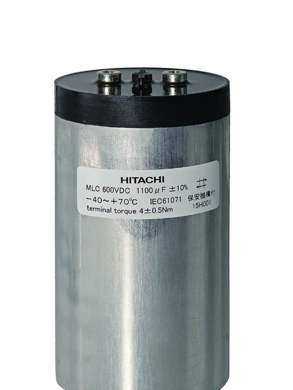
9 MLC Series (Cylindrically-Shaped Metallized Polypropylene Fim Capacitos) Cylindrically-shaped capacitor with big capacitance for wind & solar power inverters, other inverters, chopper control and charge-dischrage. High reliability of withstanding voltage due to using of our original segmented metallized film. Specifications Items Characteristics -40~+85 at 0.7 U R Operating Temperature range * -40~+80 at 0.8 U R -40~+75 at 0.9 U R -40~+70 at 1.0 U R Storage Temperature range -40~+85 Rated Voltage U R 900~1,500Vdc Voltage test between terminals U TT 1.5 U R/10s Voltage test terminals to case U TC 3,200Vac/10s Terminals (permitted Torque) M6 10 (4 ±0.5Nm) Stud Bolt (permitted Torque) M12 16/18 (7 ±1Nm) Life Time Test / Standard IEC : 2007 Dielectric Polypropylene Electrode Segmented Metal with Fuse Function Cap PBT UL94V-0 listed impregnants Epoxy/Urethane Resin UL94V-0 listed Case material Aluminium Humidity ClassF : 75%annual average, 95% 30days / year Dimensions (mm) φd φ85 φ88.5 φ100 φ116 φ140 P d T φ12 φ12 φ12 φ14 φ19 L L C L S Clearance distance (mm) Creepage distance (mm) Terminal allowance 60Arms 60Arms 60Arms 80Arms 100Arms I MAX Multiplier(1kHz ~ 10kHz) Ta Ambient Temperature 0.7 U R 0.8 U R 0.9 U R 1.0 U R Outline of drawings and dimensions M6 10 L 2 ±1 L C L 1 ±2 L S ±1 if requested d T M12 D±1 p±0.5 Marking stud bolt Projection Rib (Not for 116mm and 140 diameter items) Product symbol Example : MLC, 1100V, 580μF, ±10%, D =φ116, L = 125, with stud bolt MLC1100V587KB MLC 1100V 587 K B (... ) Type of series Capacitance code Fixing symbol code The first two digits are B:Stud Bolt significant. N:Plain Bottom Case length L 1 The last digit in dicates the number of following zeros in PF(10-12 ) Tolerance code J:±5% Rated voltage K:±10% Case dimenter φd Costomers Specification 10
10 Standard Value and case size Rated d.c voltage U R : 900Vdc Nominal Capacitance C N μf Max.ripple voltage U r : 200V Non repetitive surge voltage U S : 1,350V Voltage test between terminals U TT : 1,350Vdc/10s Voltage test terminals to case. U TC : 3,200Vac/10s Dimensions Length of Diameter the case Remarks D L 1 mm mm Maximum ripple (Arms) I max * Arms/at50 1k ~ 10kHz Maximum peak I ^ ka Maximum Surge I s ka Charge energy Please inquire us in case low frequency (commercial frequency) or frequency above 10kHz is included in ripple. Maximum permissible ripple is calculated by the value in this table with frequency and temperature correction factors. Also the maximum must be controlled below the permissible terminal. Please refer useful life graph based on ambient temperature and voltage. HOTSPOT = T a +I 2 ESR R th W J Equivalent Series Resistance ESR m Equivalent Series Inductance ESL nh Thermal resistance R th K/W Product Symbol Standard size MLC900V187KB MLC900V207KB Standard size MLC900V217KB MLC900V237KB MLC900V237KB MLC900V257KB MLC900V267KB Standard size MLC900V277KB MLC900V287KB Standard size MLC900V297KB MLC900V307KB Standard size MLC900V327KB MLC900V337KB MLC900V337KB MLC900V367KB MLC900V377KB Standard size MLC900V377KB Standard size MLC900V387KB MLC900V397KB MLC900V417KB MLC900V417KB Standard size MLC900V427KB Standard size MLC900V427KB MLC900V437KB MLC900V467KB MLC900V467KB MLC900V467KB MLC900V487KB MLC900V517KB MLC900V527KB MLC900V527KB Standard size MLC900V547KB MLC900V567KB MLC900V577KB Standard size MLC900V577KB Standard size MLC900V597KB Standard size MLC900V597KB MLC900V607KB MLC900V637KB Standard size MLC900V657KB MLC900V667KB MLC900V667KB MLC900V677KB MLC900V707KB MLC900V737KB MLC900V757KB Standard size MLC900V767KB MLC900V787KB MLC900V787KB MLC900V787KB MLC900V837KB Standard size MLC900V857KB MLC900V877KB Standard size MLC900V897KB MLC900V937KB MLC900V967KB , MLC900V108KB MLC900V108KB MLC900V118KB , Standard size MLC900V118KB MLC900V118KB Standard size MLC900V118KB , MLC900V128KB , MLC900V138KB , MLC900V148KB , MLC900V158KB MLC900V158KB , Standard size MLC900V178KB , MLC900V208KB , MLC900V238KB
11 Standard Value and case size Rated d.c voltage U R : 1,100Vdc Nominal Capacitance C N μf Max.ripple voltage U r : 250V Non repetitive surge voltage U S : 1,650V Voltage test between terminals U TT : 1,650Vdc/10s Voltage test terminals to case. U TC : 3,200Vac/10s Dimensions Length of Diameter the case Remarks D L 1 mm mm Maximum ripple (Arms) I max * Arms/at50 1k ~ 10kHz Maximum peak I ^ ka Maximum Surge I s ka Charge energy Please inquire us in case low frequency (commercial frequency) or frequency above 10kHz is included in ripple. Maximum permissible ripple is calculated by the value in this table with frequency and temperature correction factors. Also the maximum must be controlled below the permissible terminal. Please refer useful life graph based on ambient temperature and voltage. HOTSPOT = T a +I 2 ESR R th W J Equivalent Series Resistance ESR m Equivalent Series Inductance ESL nh Thermal resistance R th K/W Product Symbol Standard size MLC1100V147KB MLC1100V167KB Standard size MLC1100V177KB MLC1100V187KB MLC1100V187KB MLC1100V207KB MLC1100V207KB Standard size MLC1100V217KB Standard size MLC1100V237KB MLC1100V237KB MLC1100V237KB MLC1100V267KB Standard size MLC1100V267KB MLC1100V267KB Standard size MLC1100V297KB MLC1100V297KB MLC1100V297KB Standard size MLC1100V297KB MLC1100V317KB MLC1100V327KB MLC1100V327KB Standard size MLC1100V337KB Standard size MLC1100V337KB MLC1100V357KB MLC1100V367KB MLC1100V367KB MLC1100V377KB MLC1100V387KB MLC1100V407KB MLC1100V407KB MLC1100V417KB Standard size MLC1100V447KB MLC1100V457KB Standard size MLC1100V467KB MLC1100V467KB Standard size MLC1100V467KB Standard size MLC1100V467KB MLC1100V477KB MLC1100V507KB MLC1100V527KB MLC1100V537KB Standard size MLC1100V537KB MLC1100V537KB MLC1100V567KB MLC1100V587KB Standard size MLC1100V587KB MLC1100V597KB MLC1100V627KB MLC1100V627KB MLC1100V637KB MLC1100V657KB Standard size MLC1100V697KB MLC1100V707KB MLC1100V727KB Standard size MLC1100V727KB MLC1100V767KB MLC1100V817KB MLC1100V817KB MLC1100V907KB Standard size MLC1100V927KB Standard size MLC1100V927KB MLC1100V957KB , MLC1100V108KB MLC1100V108KB , MLC1100V118KB , MLC1100V128KB MLC1100V128KB , Standard size MLC1100V148KB , MLC1100V168KB , , MLC1100V198KB
12 Standard Value and case size Rated d.c voltage U R : 1,300Vdc Nominal Capacitance C N μf Max.ripple voltage U r : 300V Non repetitive surge voltage U S : 1,950V Voltage test between terminals U TT : 1,950Vdc/10s Voltage test terminals to case. U TC : 3,200Vac/10s Dimensions Length of Diameter the case Remarks D L 1 mm mm Maximum ripple (Arms) I max * Arms/at50 1k ~ 10kHz Maximum peak I ^ ka Maximum Surge I s ka Charge energy Please inquire us in case low frequency (commercial frequency) or frequency above 10kHz is included in ripple. Maximum permissible ripple is calculated by the value in this table with frequency and temperature correction factors. Also the maximum must be controlled below the permissible terminal. Please refer useful life graph based on ambient temperature and voltage. HOTSPOT = T a +I 2 ESR R th W J Equivalent Series Resistance ESR m Equivalent Series Inductance ESL nh Thermal resistance R th K/W Product Symbol Standard size MLC1300V107KB MLC1300V117KB Standard size MLC1300V117KB MLC1300V127KB MLC1300V137KB MLC1300V147KB MLC1300V147KB Standard size MLC1300V157KB Standard size MLC1300V167KB MLC1300V167KB MLC1300V177KB Standard size MLC1300V187KB MLC1300V187KB MLC1300V197KB MLC1300V207KB Standard size MLC1300V217KB MLC1300V217KB Standard size MLC1300V217KB MLC1300V227KB MLC1300V237KB Standard size MLC1300V237KB MLC1300V237KB MLC1300V247KB Standard size MLC1300V247KB MLC1300V257KB MLC1300V267KB MLC1300V267KB MLC1300V277KB MLC1300V287KB MLC1300V297KB MLC1300V297KB Standard size MLC1300V307KB Standard size MLC1300V317KB MLC1300V327KB MLC1300V327KB Standard size MLC1300V337KB MLC1300V337KB Standard size MLC1300V337KB MLC1300V357KB Standard size MLC1300V367KB MLC1300V377KB MLC1300V387KB MLC1300V387KB MLC1300V387KB MLC1300V417KB MLC1300V427KB Standard size MLC1300V427KB MLC1300V437KB MLC1300V457KB MLC1300V457KB MLC1300V467KB Standard size MLC1300V477KB MLC1300V487KB Standard size MLC1300V497KB MLC1300V527KB MLC1300V557KB MLC1300V557KB MLC1300V587KB Standard size MLC1300V637KB MLC1300V657KB MLC1300V657KB Standard size MLC1300V667KB MLC1300V707KB MLC1300V767KB MLC1300V777KB MLC1300V877KB MLC1300V907KB Standard size MLC1300V997KB , MLC1300V118KB , , MLC1300V138KB
13 Standard Value and case size Rated d.c voltage U R : 1,500Vdc Nominal Capacitance C N μf Max.ripple voltage U r : 350V Non repetitive surge voltage U S : 2,250V Voltage test between terminals U TT : 2,250Vdc/10s Voltage test terminals to case. U TC : 3,200Vac/10s Dimensions Length of Diameter the case Remarks D L 1 mm mm Maximum ripple (Arms) I max * Arms/at50 1k ~ 10kHz Maximum peak I ^ ka Maximum Surge I s ka Charge energy Please inquire us in case low frequency (commercial frequency) or frequency above 10kHz is included in ripple. Maximum permissible ripple is calculated by the value in this table with frequency and temperature correction factors. Also the maximum must be controlled below the permissible terminal. Please refer useful life graph based on ambient temperature and voltage. HOTSPOT = T a +I 2 ESR R th W J Equivalent Series Resistance ESR m Equivalent Series Inductance ESL nh Thermal resistance R th K/W Product Symbol Standard size MLC1500V706KB MLC1500V806KB Standard size MLC1500V806KB MLC1500V906KB MLC1500V906KB MLC1500V107KB MLC1500V107KB Standard size MLC1500V117KB MLC1500V117KB Standard size MLC1500V117KB MLC1500V127KB MLC1500V137KB Standard size MLC1500V137KB MLC1500V137KB Standard size MLC1500V157KB MLC1500V157KB MLC1500V157KB Standard size MLC1500V157KB MLC1500V167KB MLC1500V167KB MLC1500V167KB MLC1500V177KB Standard size MLC1500V177KB Standard size MLC1500V177KB MLC1500V187KB MLC1500V187KB MLC1500V187KB MLC1500V197KB MLC1500V207KB MLC1500V207KB MLC1500V207KB Standard size MLC1500V217KB Standard size MLC1500V237KB MLC1500V237KB MLC1500V237KB Standard size MLC1500V237KB Standard size MLC1500V237KB MLC1500V247KB MLC1500V257KB Standard size MLC1500V267KB MLC1500V267KB MLC1500V277KB MLC1500V277KB MLC1500V287KB MLC1500V307KB MLC1500V307KB Standard size MLC1500V307KB MLC1500V327KB MLC1500V327KB MLC1500V327KB MLC1500V337KB Standard size MLC1500V347KB MLC1500V357KB Standard size MLC1500V367KB MLC1500V377KB MLC1500V397KB MLC1500V407KB MLC1500V417KB MLC1500V467KB Standard size MLC1500V467KB Standard size MLC1500V477KB MLC1500V487KB MLC1500V517KB MLC1500V547KB MLC1500V577KB MLC1500V647KB MLC1500V647KB Standard size MLC1500V727KB MLC1500V817KB , MLC1500V967KB

14 NEW! MLC2 Series (Cylindrically-Shaped Metallized Polypropylene Fim Capacitos) Approx. 15% smaller than MLC series in volume. Cylindrically-shaped capacitor with big capacitance for wind & solar power inverters, other inverters, chopper control and charge-dischrage. High reliability of withstanding voltage due to using of our original segmented metallized film. Specifications Items Characteristics -40~+85 at 0.7 U R Operating Temperature range * -40~+80 at 0.8 U R -40~+75 at 0.9 U R -40~+70 at 1.0 U R Storage Temperature range -40~+85 Rated Voltage U R 800~900Vdc Voltage test between terminals U TT 1.5 U R/10s Voltage test terminals to case U TC 3,200Vac/10s Terminals (permitted Torque) M6 10 (4 ±0.5Nm) Stud Bolt (permitted Torque) M12 16/18 (7 ±1Nm) Life Time Test / Standard IEC : 2007 Dielectric Polypropylene Electrode Segmented Metal with Fuse Function Cap PBT UL94V-0 listed impregnants Epoxy/Urethane Resin UL94V-0 listed Case material Aluminium Humidity ClassF : 75%annual average, 95% 30days / year Dimensions (mm) φd φ85 φ88.5 φ100 φ116 φ140 P d T φ12 φ12 φ12 φ14 φ19 L L C L S Clearance distance (mm) Creepage distance (mm) Terminal allowance 60Arms 60Arms 60Arms 80Arms 100Arms I MAX Multiplier(1kHz ~ 10kHz) Ta Ambient Temperature 0.7 U R 0.8 U R 0.9 U R 1.0 U R Outline of drawings and dimensions M6 10 L 2 ±1 L C L 1 ±2 L S ±1 if requested d T M12 D±1 p±0.5 Marking stud bolt Projection Rib (Not for 116mm and 140 diameter items) Product symbol Example : MLC, 800V, 1200μF, ±10%, D =φ116, L = 125, with stud bolt MLC800V128KB MLC2 800V 128 K B (...) Type of series Capacitance code Fixing symbol code The first two digits are B:Stud Bolt significant. N:Plain Bottom Case length L 1 The last digit in dicates the number of following zeros in PF Tolerance code (128: pf) J:±5% Rated voltage K:±10% Case dimenter φd Costomers Specification 15
15 Standard Value and case size Rated d.c voltage U R : 800Vdc Nominal Capacitance C N μf Max.ripple voltage U r : 200V Non repetitive surge voltage U S : 1,200V Voltage test between terminals U TT : 1,200Vdc/10s Voltage test terminals to case. U TC : 3,200Vac/10s Dimensions Length of Diameter the case D L 1 mm mm Remarks Maximum ripple (Arms) I max * Arms/at50 1k ~ 10kHz Maximum peak I ^ ka Maximum Surge I s ka Charge energy W J Equivalent Series Resistance ESR m Equivalent Series Inductance ESL nh Thermal resistance R th K/W Product Symbol Standard size MLC2800V307KB MLC2800V337KB Standard size MLC2800V347KB MLC2800V377KB MLC2800V377KB MLC2800V417KB Standard size MLC2800V447KB MLC2800V457KB MLC2800V477KB Standard size MLC2800V487KB MLC2800V497KB Standard size MLC2800V537KB MLC2800V547KB MLC2800V547KB MLC2800V607KB Standard size MLC2800V617KB MLC2800V617KB Standard size MLC2800V627KB MLC2800V637KB MLC2800V677KB Standard size MLC2800V687KB MLC2800V687KB Standard size MLC2800V697KB MLC2800V707KB MLC2800V757KB MLC2800V767KB MLC2800V767KB MLC2800V787KB MLC2800V837KB MLC2800V847KB MLC2800V857KB Standard size MLC2800V897KB MLC2800V927KB Standard size MLC2800V937KB MLC2800V947KB Standard size MLC2800V967KB Standard size MLC2800V977KB MLC2800V987KB MLC2800V108KB Standard size MLC2800V108KB , MLC2800V108KB MLC2800V108KB MLC2800V108KB , MLC2800V118KB MLC2800V128KB MLC2800V128KB , MLC2800V128KB MLC2800V128KB Standard size MLC2800V128KB MLC2800V128KB , Standard size MLC2800V138KB MLC2800V138KB , MLC2800V148KB Standard size MLC2800V148KB , MLC2800V158KB MLC2800V158KB , MLC2800V168KB , MLC2800V178KB , MLC2800V188KB Standard size MLC2800V188KB , Standard size MLC2800V198KB MLC2800V198KB , MLC2800V208KB , MLC2800V218KB , MLC2800V238KB , MLC2800V258KB MLC2800V258KB , Standard size MLC2800V298KB , MLC2800V338KB , MLC2800V388KB Please inquire us in case low frequency (commercial frequency) or frequency above 10kHz is included in ripple. Maximum permissible ripple is calculated by the value in this table with frequency and temperature correction factors. Also the maximum must be controlled below the permissible terminal. Please refer useful life graph based on ambient temperature and voltage. HOTSPOT = T a +I 2 ESR R th 16
16 Standard Value and case size Rated d.c voltage U R : 900Vdc Nominal Capacitance C N μf Max.ripple voltage U r : 200V Non repetitive surge voltage U S : 1,350V Voltage test between terminals U TT : 1,350Vdc/10s Voltage test terminals to case. U TC : 3,200Vac/10s Dimensions Length of Diameter the case D L 1 mm mm Remarks Maximum ripple (Arms) I max * Arms/at50 1k ~ 10kHz Maximum peak I ^ ka Maximum Surge I s ka Charge energy W J Equivalent Series Resistance ESR m Equivalent Series Inductance ESL nh Thermal resistance R th K/W Product Symbol Standard size MLC2900V237KB MLC2900V257KB Standard size MLC2900V257KB MLC2900V287KB MLC2900V287KB MLC2900V317KB MLC2900V327KB MLC2900V357KB Standard size MLC2900V357KB Standard size MLC2900V367KB MLC2900V397KB Standard size MLC2900V407KB MLC2900V417KB MLC2900V437KB MLC2900V457KB Standard size MLC2900V467KB MLC2900V477KB Standard size MLC2900V477KB MLC2900V487KB MLC2900V517KB Standard size MLC2900V517KB MLC2900V517KB MLC2900V537KB Standard size MLC2900V547KB MLC2900V577KB MLC2900V577KB MLC2900V577KB MLC2900V597KB MLC2900V637KB MLC2900V647KB MLC2900V657KB MLC2900V697KB Standard size MLC2900V697KB MLC2900V717KB Standard size MLC2900V717KB Standard size MLC2900V737KB Standard size MLC2900V737KB MLC2900V787KB MLC2900V787KB Standard size MLC2900V817KB MLC2900V827KB MLC2900V837KB MLC2900V867KB MLC2900V877KB MLC2900V917KB MLC2900V937KB Standard size MLC2900V947KB MLC2900V967KB MLC2900V977KB MLC2900V987KB MLC2900V108KB , Standard size MLC2900V108KB MLC2900V108KB MLC2900V118KB , MLC2900V118KB Standard size MLC2900V118KB , MLC2900V128KB , MLC2900V138KB MLC2900V148KB , Standard size MLC2900V148KB MLC2900V148KB Standard size MLC2900V148KB , MLC2900V158KB , MLC2900V168KB , MLC2900V178KB , MLC2900V198KB MLC2900V198KB , Standard size MLC2900V228KB , MLC2900V258KB , MLC2900V298KB Please inquire us in case low frequency (commercial frequency) or frequency above 10kHz is included in ripple. Maximum permissible ripple is calculated by the value in this table with frequency and temperature correction factors. Also the maximum must be controlled below the permissible terminal. Please refer useful life graph based on ambient temperature and voltage. HOTSPOT = T a +I 2 ESR R th 17
 700, 900, 1,100 V.DC 1.5 U R/10s lead (1.")
 Lead (mm) L T H P1 P2 d 43.0 21.5 38.5 37.5 10.2 1.0 42.0 30.0 45.0 37.5 20.3 1.0 57.5 25.0 45.0 52.5 10.2 1.2 57.5 35.0 50.0 52.5 20.3 1.2 57.5 35.0 60.")
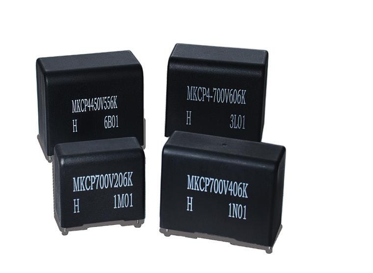
17 NEW! MKC-P4 Series (Resin-encased Metallized Polyester Film Capacitors) Features Suitable for DC filter and DC link circuit Plastic case and filling resin materials conform to UL94V-0 Specifications Items Operating Temperature range Rated Voltage U R Voltage test between terminals Terminals Description - 40 ~+ 105 (voltage derating is required at +85 ) 700, 900, 1,100 V.DC 1.5 U R/10s lead (1.0φ,1.2φ) Life Time Test / Standard IEC : 2007 Dielectric polypropylene Electrode no internal safety device (optional : segmented metallization design) Case UL94-V0 Filling material UL94-V0 Environmental regulations Comply with RoHS Dimension Case (mm) Lead (mm) L T H P1 P2 d Product symbol : (Example) MKC-P4 Series 700V.DC 20μF ±10% MKC-P4-700V 206 K S Type of series Suffix Capacitance tolerance codfe Capacitance codfe Rated voltage code Outline of drawings and dimensions L T Circuitry Marking H P1 φd P Standard Value and case size Rated d.c voltage U R : 700Vdc Voltage test between terminals U TT : 1,050Vdc/10s 70 =800vdc, 85 =700vdc, 105 =500vdc Nominal Capacitance C N μf L mm Dimensions T mm H mm dv/dt dv/dt V/us Maximum peak Ipeak A Maximum ripple (Arms) I max Arms/at85 1k ~ 10kHz Equivalent Series Resistance ESR m Equivalent Series Inductance ESL nh Product Symbol MKC-P4-700V206K MKC-P4-700V306K MKC-P4-700V356KS MKC-P4-700V356K MKC-P4-700V406K MKC-P4-700V556K MKC-P4-700V606K MKC-P4-700V656K MKC-P4-700V706K MKC-P4-700V806K Rated d.c voltage U R : 900Vdc Voltage test between terminals U TT : 1,350Vdc/10s 70 =1,100vdc, 85 =900vdc, 105 =650vdc MKC-P4-900V106K MKC-P4-900V126K MKC-P4-900V156K MKC-P4-900V206KS MKC-P4-900V206K MKC-P4-900V356K MKC-P4-900V406K MKC-P4-900V456K MKC-P4-900V506K Rated d.c voltage U R : 1,100Vdc Voltage test between terminals U TT : 1,650Vdc/10s 70 =1,300vdc, 85 =1,100vdc, 105 =800vdc MKC-P4-1100V705K MKC-P4-1100V805K MKC-P4-1100V106K MKC-P4-1100V126K MKC-P4-1100V156K MKC-P4-1100V226K MKC-P4-1100V256K MKC-P4-1100V306K 18
18 MEMO 19
 Specifications E51(DC)Series (for DC) Item Specification Category temperature range -25 ~+ 70 (Includes self temperature rise) Storage")
19 NEW! E51 / E51(AC) Series Features High voltage range and low inductance capacitors. E51 series are made in dry technology. Capacitors both for AC/DC application are available. (Cylindrical Metallized Polypropylene Film Capacitors) Specifications E51(DC)Series (for DC) Item Specification Category temperature range -25 ~+ 70 (Includes self temperature rise) Storage temperature -40 ~+ 85 Rated voltage U N 1,000 ~ 50,000Vdc Terminal (torque) M8 12 (7Nm) Standards IEC : 2007 Dielectric Polypropylene Dielectric dissipation factor (tanδ 0 ) Capacitance tolerance ±10% (optional ±5%) Safety devices - Impregnant Solid resin based on vegetable oil, Non PCB Material of case Plastic (UL94V-0) Environmental regulations Comply with RoHS E51(AC)Series (for AC) Item Specification Category temperature range -25 ~+ 70 (Includes self temperature rise) Storage temperature -40 ~+ 85 Rated voltage U N 2,000 ~ 3,5000Vac (3,200 ~ 50,000Vdc) Terminal (torque) M8 12 (7Nm) Standards IEC : 2007 Dielectric Polypropylene Dielectric dissipation factor (tanδ 0 ) Capacitance tolerance ±10% (optional ±5%) Safety devices - Impregnant Solid resin based on vegetable oil, Non PCB Material of case Plastic (UL94V-0) Environmental regulations Comply with RoHS D(refer to catalog) 20 Dimensions L(refer to catalog) L+8 Item Terminal code Can material Terminal Degree of protection Humidity class Clearance in air Creepage distance Specification R2 Plastic (UL94V-0) Axial thread M8 12 Torque : 7Nm I max (terminal) : 100A IP00 F L+ D - 20mm L+ D - 20mm M
20 Standard Value and Case Size (E51Series) Rated DC Voltage U N (DC) Vdc Rated Capacitance C N μf Case size Diameter D mm Length L mm Rated ripple voltage U r V Rated DC voltage U N(DC): 1,300 ~ 2,700Vdc Surge voltage U s V Energy Contents W J Series resistance (reference) R S m Thermal resistance (reference) R th K/W Max Max peak I max Î Arms ka Max surge I S ka Self inductance (reference) ESL nh Weight kg Part number 1, , E51.S18-704R20/H 2, , E51.L35-803R20/H 2, , E51.P35-174R20/H 2, , E51.P13-253R20/H 2, , E51.P17-503R20/H 2, , E51.S12-403R20/H Rated DC voltage U N(DC): 3,000 ~ 3,600Vdc 3, , E51.P15-183R20/H 3, , E51.P25-803R20/H 3, ,500 1, E51.S35-354R20/H 3, ,500 1, E51.S46-404R20/H 3, , E51.P35-863R20/H 3, , E51.L20-153R20/H 3, , E51.P20-333R20/H 3, ,250 3, E51.S71-504R20/H 3, , E51.R24-803R20/H 3, ,400 1, E51.S30-224R20/H Rated DC voltage U N(DC): 4,000 ~ 5,600Vdc 4, ,850 6, E51.R17-802R20/H 4, ,850 6, E51.S17-163R20/H 4, ,000 1, E51.S56-224R20/H 4, , E51.L14-802R20/H 4, , E51.P35-453R20/H 4, , E51.L18-802R20/H 4, , E51.P13-802R20/H 4, ,750 3, E51.S71-304R20/H 4, ,000 7,050 2, E51.S43-194R20/H 5, ,000 7, E51.L15-462R20/H 5, ,100 8, E51.L12-102R20/H Rated DC voltage U N(DC): 6,000 ~ 9,300Vdc 6, , E51.R20-303R20/H 6, ,200 9, E51.L25-682R20/H 6, ,200 9, E51.P25-153R20/H 6, ,200 9, E51.P35-203R20/H 6, ,200 9,450 1, E51.S35-513R20/H 8, ,400 12, E51.P22-502R20/H 8, ,400 12, E51.P32-103R20/H 8, ,400 12,000 1, E51.S35-403R20/H 8, ,400 12, E51.L16-221R20/H 8, ,950 12, E51.L16-501R20/H 8, ,400 12, E51.P16-102R20/H 9, ,500 13, E51.P35-902R20/H 9, ,500 13,950 1, E51.S35-253R20/H Rated DC voltage U N(DC): 10,000 ~ 50,000Vdc 10, ,000 15, E51.L16-251R20/H 10, ,000 15, E51.R32-402R20/H 10, ,000 15, E51.S48-452R20/H 10, ,500 15, E51.P35-103R20/H 12, ,100 18,000 1, E51.S56-243R20/H 12, ,100 18, E51.L20-221R20/H 12, ,100 18, E51.L20-251R20/H 12, ,100 18, E51.R20-102R20/H 13, ,000 19, E51.L28-251R20/H 14, ,400 21, E51.R35-502R20/H 14, ,400 21, E51.S35-103R20/H 15, ,600 22, E51.L28-102R20/H 15, ,600 22, E51.P28-202R20/H 15, ,600 22,500 1, E51.S38-103R20/H 15, ,600 22,500 1, E51.S46-153R20/H 15, ,600 22,500 2, E51.S56-203R20/H 20, ,000 30, E51.P35-132R20/H 20, ,000 30, E51.P35-152R20/H 25, ,600 37,500 3, E51.S71-103R20/H 30, ,800 45, E51.P44-102R20/H 30, ,800 45,000 2, E51.S71-502R20/H 35, ,600 52, E51.P44-201R20/H 35, ,800 52,500 3, E51.S78-502R20/H 40, ,700 60,000 1, E51.S63-222R20/H 50, ,000 60, E51.S71-501R20/H 21
21 Standard Value and Case Size (E51series (AC)) Rated AC Voltage U N (AC) Vdc Rated DC Voltage U N (DC) Vdc Rated Capacitance C N μf Case size Diameter D mm Length L mm Rated AC voltage U N(AC): 2,000 ~ 3,250Vac Rated ripple voltage U r V Surge voltage U s V Energy Contents W J U rms: 1,650 ~ 2,300V rms Series resistance (reference) R S m Thermal resistance (reference) R th Max I max Max peak Î K/W Arms ka Max surge I S ka Self inductance Weight (reference) ESL nh kg Part number 2,350 4, ,650 6, E51.L15-152R20/H 2, ,650 3, E51.L25-302R20/H 2,500 6, ,770 9, E51.P13-102R20/H 2,550 3, ,800 4, E51.L12-102R21/H 2,700 4, ,910 6, E51.R11-402R20/H 2,900 5, ,050 7, E51.R11-3-2R20/H 3, ,100 6, E51.L10-471R20/H 3, ,200 7, E51.R26-502R20/H 3, ,300 4, E51.L16-751R20/H 3,200 7, ,260 10, E51.L13-501R20/H Rated AC voltage U N(AC): 3,500Vac U rms: 2,500V rms 3,500 6, ,500 9, E51.L12-221R20/H 3,500 6, ,500 9, E51.L12-251R20/H 3,500 6, ,500 9, E51.L12-331R20/H 3,500 6, ,500 9, E51.L12-501R20/H 3,200 5, ,250 9, E51.L12-681R20/H 3,500 6, ,500 9, E51.P10-751R20/H 3,500 6, ,500 9, E51.P13-132R20/H 3,500 6, ,500 9, E51.P13-152R20/H 2,450 6, ,700 9, E51.P14-202R20/H Rated AC voltage U N(AC): 3,850 ~ 4,300Vac U rms: 2,700 ~ 3,050V rms 3, ,700 5, E51.P28-252R20/H 4, ,000 6, E51.P15-112R20/H 4, ,050 6, E51.L16-501R21/H 4, ,050 6, E51.L20-801R20/H Rated AC voltage U N(AC): 4,550Vac U rms: 3,200V rms 4,550 7, ,200 10, E51.L13-221R20/H 4,550 7, ,200 10, E51.L13-331R20/H 3,150 7, ,200 10, E51.P13-751R20/H 2,500 6, ,770 9, E51.P13-102R20/H 4,400 6, ,100 10, E51.P15-152R21/H 4, ,200 6, E51.P27-112R20/H 2,800 4, ,000 10, E51.P14-132R20/H 4,550 7, ,200 10, E51.R13-152R20/H 4,550 7, ,200 10, E51.R13-202R20/H Rated AC voltage U N(AC): 4,700 ~ 5,850Vac U rms: 3,300 ~ 4,150V rms 4, ,300 7, E51.L25-751R20/H 5, ,500 10, E51.L21-471R20/H 5,000 10, ,540 15, E51.P20-501R20/H 5,000 10, ,540 7, E51.P25-102R20/H 5, ,600 9, E51.R35-162R20/H 5, ,600 10, E51.P20-242R21/H 5, ,600 9, E51.R46-262R20/H 5, ,700 7, E51.P20-112R20/H 5, ,150 12, E51.P16-471R20/H Rated AC voltage U N(AC): 6,000 ~ 9,620Vac U rms: 4,600 ~ 6,800V rms 6,300 9, ,450 13, E51.L16-131R20/H 6,300 9, ,450 13, E51.L20-141R20/H 6, ,600 9, E51.S35-402R20/H 7, ,300 11, E51.S35-132R20/H 8, ,300 13, E51.P21-241R20/H 9, ,510 13, E51.P27-501R20/H 9, ,800 14, E51.R25-501R20/H Rated AC voltage U N(AC): 10,000 ~ 35,000Vac U rms: 7,100 ~ 25,000V rms 10,000 14, ,100 15, E51.R39-102R20/H 10,000 14, ,100 15, E51.S39-192R20/H 12, ,000 27, E51.P35-201R20/H 10, ,070 15, E51.P35-501R20/H 20,000 26, ,000 30, E51.R35-301R20/H 20,000 30, ,140 45, E51.S71-102R20/H 20,000 50, ,140 60, E51.S71-501R20/H 22
22 NEW! E53(AC) Series Features High voltage range and ultra low inductance capacitors. E53(AC) series are made in dry technology. For AC application. (AC Cylindrical Metallized Polypropylene Film Capacitors) Specifications Item Specification Category temperature range - 25 ~+ 70 ( + 85 / Includes self temperature rise) Storage temperature - 40 ~+ 85 Rated voltage (U N) 280 ~ 2,450Vac (500 ~ 7,200Vdc) Terminal (torque) M6 10 (7Nm) / M8 10 (7Nm) Standards IEC : 2007 Dielectric Polypropylene Dielectric dissipation factor (tanδ 0 ) Capacitance tolerance ±10% (optional ±5%) Safety devices - Impregnant Solid resin based on vegetable oil, Non PCB Material of case Plastic (UL94V-0) Environmental regulations Comply with RoHS Dimensions Item Terminal code Can material T1 Terminal T2 Degree of protection Humidity class Specification T1 / T2 Plastic (UL94V-0) Axial thread M6 10 Torque : 4Nm I max (terminal) : 60A Axial thread M8 10 Torque : 7Nm I max (terminal) : 100A IP00 G D(refer to catalog)) T1 M6 10 T2 M8 10 L(refer to catalog) L+7 L(refer to catalog) L
23 Standard Value and Case Size Rated Capacitance C N μf Case size Diameter Length D L mm mm Energy Contents W J Series resistance (reference) R S m Thermal resistance (reference) R th K/W Max Max peak I max Î Arms ka Rated voltage U N:550Vdc / 280Vac U rms: 200V rms Us: 825V U TT: 825Vdc Max surge I S ka Self inductance (reference) ESL nh Terminal Clearance in air L mm Creepage distance K mm Weight kg Part number T E53.H56-503T10/H T E53.M56-104T20/H T E53.P56-204T20/H T E53.P56-204T20/H T E53.R56-274T20/H T E53.R10-384T20/H Rated voltage U N:700Vdc / 350Vac U rms: 250V rms Us: 1,050V U TT: 1,050Vdc T E53.H56-333T10/H T E53.M56-683T20/H T E53.P56-124T20/H T E53.Q56-154T20/H T E53.R56-204T20/H T E53.R10-314T20/H Rated voltage U N:900Vdc / 350Vac U rms: 250V rms Us: 1,350V U TT: 1,350Vdc T E53.H56-303T10/H T E53.M56-603T20/H T E53.P56-104T20/H T E53.Q56-124T20/H T E53.R56-144T20/H T E53.R10-274T20/H Rated voltage U N:1,100Vdc / 350Vac U rms: 250V rms Us: 1,650V U TT: 1,650Vdc T E53.H56-123T10/H T E53.H56-153T10/H T E53.M56-253T20/H T E53.P56-503T20/H T E53.Q56-603T20/H T E53.R56-803T20/H T E53.R10-184T20/H Rated voltage U N:1,400Vdc / 350Vac U rms: 250V rms Us: 2,100V U TT: 2,100Vdc T E53.H56-802T10/H T E53.M56-163T20/H T E53.P56-303T20/H T E53.Q56-403T20/H T E53.R56-503T20/H T E53.R10-114T20/H Rated voltage U N:1,700Vdc / 700Vac U rms: 500V rms Us: 2,550V U TT: 2,550Vdc T E53.H56-472T10/H T E53.M56-103T20/H T E53.P56-163T20/H T E53.Q56-223T20/H T E53.R56-333T20/H T E53.R10-683T20/H Rated voltage U N:2,000Vdc / 700Vac U rms: 500V rms Us: 3,000V U TT: 3,000Vdc T E53.H56-332T10/H T E53.M56-802T20/H T E53.P56-143T20/H T E53.Q56-183T20/H T E53.R56-243T20/H T E53.R10-533T20/H Rated voltage U N:2,250Vdc / 700Vac U rms: 500V rms Us: 3,375V U TT: 3,375Vdc T E53.H56-252T10/H T E53.M56-602T20/H T E53.P56-103T20/H T E53.Q56-153T20/H T E53.R56-183T20/H T E53.R10-403T20/H Rated voltage U N:2,800Vdc / 700Vac U rms: 500V rms Us: 4,200V U TT: 4,200Vdc T E53.H56-152T10/H T E53.M56-332T20/H T E53.P56-752T20/H T E53.Q56-103T20/H T E53.R56-123T20/H T E53.R10-253T20/H Rated voltage U N:3,200Vdc / 1,050Vac U rms: 750V rms Us: 4,800V U TT: 4,800Vdc T E53.H56-102T10/H T E53.M56-252T20/H T E53.P56-402T20/H T E53.Q56-602T20/H T E53.R56-702T20/H 24
24 Standard Value and Case Size Rated Capacitance C N μf Case size Diameter Length D L mm mm Energy Contents W J Series resistance (reference) R S m Thermal resistance (reference) R th K/W Max Max peak I max Î Arms ka Max surge I S ka Rated voltage U N:2,450Vdc / 1,400Vac U rms: 1,000V rms Us: 3,675V U TT: 3,675Vdc Self inductance (reference) ESL nh Terminal Clearance in air L mm Creepage distance K mm Weight kg Part number T E53.H56-122T10/H T E53.M56-242T20/H T E53.P56-422T20/H T E53.Q56-522T20/H T E53.R56-642T20/H Rated voltage U N:3,600Vdc / 1,400Vac U rms: 1,000V rms Us: 5,400V U TT: 5,400Vdc T E53.R10-802T20/H T E53.R10-103T20/H Rated voltage U N:3,750Vdc / 2,100Vac U rms: 1,500V rms Us: 5,625V U TT: 5,625Vdc T E53.H56-471T10/H T E53.M56-112T20/H T E53.P56-172T20/H T E53.Q56-222T20/H T E53.R56-272T20/H Rated voltage U N:5,000Vdc / 2,100Vac U rms: 1,500V rms Us: 7,500V U TT: 7,500Vdc T E53.R10-302T21/H T E53.R10-402T21/H Rated voltage U N:5,600Vdc / 2,450Vac U rms: 1,750V rms Us: 8,400V U TT: 8,400Vdc T E53.H97-221T10/H T E53.H97-251T10/H T E53.H97-501T10/H Rated voltage U N:7,200Vdc / 2,450Vac U rms: 1,750V rms Us: 10,800V U TT: 10,800Vdc T E53.H97-221T11/H T E53.H97-251T11/H 25
 Specifications Item Specification Category temperature range - 25 ~+ 70 ( + 85 / Includes self temperature rise) Storage temperature - 40 ~+")
25 NEW! E53H Series Features High voltage range and ultra low inductance capacitors. E53H series are made in dry technology. Robust studs with M8 thread allows for radial connection. (DC Cylindrical Metallized Polypropylene Film Capacitors) Specifications Item Specification Category temperature range - 25 ~+ 70 ( + 85 / Includes self temperature rise) Storage temperature - 40 ~+ 85 Rated voltage (U N) 600 ~ 2,200Vdc Terminal (torque) M8 20 (4Nm) Standards IEC : 2007 Dielectric Polypropylene Dielectric dissipation factor (tanδ 0 ) Capacitance tolerance ±10% (optional ±5%) Safety devices - Impregnant Solid resin based on vegetable oil, Non PCB Material of case Plastic (UL94V-0) Environmental regulations Comply with RoHS Dimensions φ5.5 Item Terminal code Can material Terminal Degree of protection Humidity class Specification H1 Plastic (UL94V-0) Radial thread M8 20 Torque : 4Nm I max (terminal) : 100A IP00 F 25 L(refer to catalog) (ca. 83.5) 45 M
26 Standard Value and Case Size Rated Capacitance C N μf Case size Diameter D 1 mm Length L 1 mm Rated ripple voltage U r V Energy Contents W J Series resistance (reference) R S m Rated voltage U N:600Vdc Us: 900V UTT: 900Vdc Thermal resistance (reference) R th K/W Max Max peak I max Î Arms ka Max surge I S ka Self inductance (reference) ESL nh Clearance in air L mm Creepage distance K mm Weight kg Part number E53.N51-204H11/H E53.N64-284H10/H E53.N76-404H11/H Rated voltage U N:700Vdc Us: 1,050V UTT: 1,050Vdc E53.N51-154H11/H E53.N64-204H10/H E53.N76-304H11/H Rated voltage U N:900Vdc Us: 1,350V UTT: 1,350Vdc E53.N51-124H11/H E53.N64-154H11/H E53.N76-244H11/H Rated voltage U N:1,100Vdc Us: 1,650V UTT: 1,650Vdc E53.N51-753H11/H E53.N64-104H10/H E53.N76-154H11/H Rated voltage U N:1,300Vdc Us: 1,950V UTT: 1,950Vdc E53.N51-503H11/H E53.N64-683H10/H E53.N76-104H11/H Rated voltage U N:1,500Vdc Us: 2,250V UTT: 2,250Vdc E53.N51-383H11/H E53.N64-503H10/H E53.N76-753H11/H Rated voltage U N:1,800Vdc Us: 2,700V UTT: 2,700Vdc E53.N51-303H11/H E53.N64-403H10/H E53.N76-603H11/H Rated voltage U N:2,000Vdc Us: 3,000V UTT: 3,000Vdc E53.N51-133H10/H E53.N64-303H10/H E53.N76-433H10/H Rated voltage U N:2,200Vdc Us: 3,300V UTT: 3,300Vdc E53.N64-253H10/H E53.N76-353H10/H 27
 Specifications Item Specification Category temperature range - 25 ~+ 70 ( + 85 / Includes self temperature rise) Storage temperature - 40 ~+")
27 NEW! E55 Series Features High voltage range and ultra low inductance capacitors. E55 series are made in dry technology. For DC application. (DC Cylindrical Metallized Polypropylene Film Capacitors) Specifications Item Specification Category temperature range - 25 ~+ 70 ( + 85 / Includes self temperature rise) Storage temperature - 40 ~+ 85 Rated voltage (U N) 900 ~ 5,000Vdc Terminal (torque) M6 10 (4Nm) / M8 10 (7Nm) Standards IEC : 2007 Dielectric Polypropylene Dielectric dissipation factor (tanδ 0 ) Capacitance tolerance ±10% (optional ±5%) Safety devices - Impregnant Solid resin based on vegetable oil, Non PCB Material of case Plastic (UL94V-0) Environmental regulations Comply with RoHS Dimensions Item Terminal code Can material T1 Terminal T2 Degree of protection Humidity class Specification T1 / T2 Plastic (UL94V-0) Axial thread M6 10 Torque : 4Nm I max (terminal) : 60A Axial thread M8 10 Torque : 7Nm I max (terminal) : 100A IP00 G T1 M6 10 L(refer to catalog) L+7 T2 D(refer to catalog) M8 10 L(refer to catalog) L Standard Value and Case Size Rated Capacitance Case size Diameter Length Rated ripple voltage U r V Energy Contents Series resistance (reference) R S m C N D L W μf mm mm J Rated voltage U N: 900Vdc Us: 1,350V U TT: 1,350Vdc Thermal resistance (reference) R th K/W Max Max peak I max Î Arms ka Max surge I S ka Self inductance (reference) Terminal ESL nh Clearance in air L mm Creepage distance K mm Weight kg Part number T E55.H56-473T10/H T E55.Q56-254T20/H Rated voltage U N: 1,300Vdc Us: 1,950V U TT: 1,950Vdc T E55.M56-503T20/H T E55.P56-903T20/H Rated voltage U N: 1,800Vdc Us: 2,700V U TT: 2,700Vdc T E55.M56-223T20/H T E55.R56-803T20/H Rated voltage U N: 2,000Vdc Us: 3,000V U TT: 3,000Vdc T E55.R56-503T20/H Rated voltage U N: 2,400Vdc Us: 3,600V U TT: 3,600Vdc T E55.R56-303T20/H Rated voltage U N: 2,800Vdc Us: 4,200V U TT: 4,200Vdc T E55.Q56-183T20/H Rated voltage U N: 3,200Vdc Us: 4,800V UTT: 4,800Vdc , T E55.R56-103T20/H Rated voltage U N: 5,000Vdc Us: 7,500V U TT: 7,500Vdc , T E55.R10-103T20/H 28
28 MEMO 29
29 NEW! E59 Series Features (Custom Designed AC/DC Capacitors in Rectangular Case) Custom designed AC / DC capacitor in rectangular case. An irreversible pressure switch can be used for external monitoring of the internal pressure. (optional) Specifications Item Specification Category temperature range - 40 ~+ 70 ( + 85 / Includes self temperature rise) Storage temperature - 50 ~+ 85 Rated voltage (U N) 500 ~ 25,000V DC / 250 ~ 10,000V AC Standards IEC : 2007 Dielectric Polypropylene Dielectric dissipation factor (tanδ 0 ) Capacitance tolerance ±10% (optional ±5%) Safety devices Optional pressure switch for external monitoring of the internal pressure (hermetical construction only) Impregnant Solid polyurethane Material of case Aluminum Environmental regulations Comply with RoHS Standard Value and Case Size Case Dimension Maximum capacitance per case (Milifarad) L W H ( mm ) 500V 900V 1100V 1300V 1700V 2000V 2400V 2700V 3000V 3500V 4000V 5000V ー ー ー ー ー ー ー ー ー ー ー ー ー ー ー ー ー ー ー ー Other values and designs on request. 30


30 Terminals for E59 series M12 65φ M16 φ46 M12 φ58 M φ46 M F1 M12 30 terminal F4 M12 30 terminal F5 M12 30 terminal F6 M16 30 terminal φ58 φ28 M8 16 φ58 φ28 M φ φ32 M F4 im8 12 terminal F4 im8 16 terminal F5 im8 16 terminal F6 im12 30 terminal Irreversible Pressure Switch Type Mechanical pressure switch with a diaphragm of EPDM or stainless steel, and a change-over contact for converting pressure into an electrical switching signal, RoHS-compliant. Contacts Cable-plugs 6.3mm x 0.8mm; we recommend using insulated cable plugs if operating the switch without protective cap. Functions The pressure switch just provides a signal for information about the rising pressure inside the capacitor. The pressure switch does NOT have the following functions. provide detailed data about the exact pressure inside the capacitor interrupt the path and disconnect the capacitor from its supply Table. The switch can be used for the following signal s : Type of load Type of Maximum voltage Maximum Inductive AC 250V rms 2A DC 24V 1A Ohmic AC 250V rms 4A DC 24V 2A Our pressure switch is designed as an SPDT (Single Pole, Double Throw) device. It can therefore be used for the following options. Fig. Pressure switch Option Advantage Disadvantage Opening switch Monitoring of the conductor power losses by permanent risk of electrochemical corrosion Closing switch Change-over switch No, no power losses No electrochemical corrosion Additional verification of the switching contact, minimization of false alarms No conductor monitoring, risk of monitoring failure going unnoticed Risk of incorrect cable connection during assembly process Fig. Circuitry of pressure switch Protective cap (optional, IP54) A protection cap made of NBT can be ordered as an accessory. The cap can be used for additional protection of the pressure switch from environmental impact, for insulation and protection from accidental contact. Fig. Protective cap 31

31 NEW! E62(AC) Series Features (AC Cylindrical Metallized Polypropylene Film Capacitos) Perfect for non-sinusoidal voltages and pulsed s. Housed in a hermetically sealed aluminum can which is filled with environmentally friendly plant oil as standard. The integrated overpressure disconnector ensure safe operation and controlled disconnection in the event of overload or failure at the end of operating life. Specifications Item Specification Category temperature range - 40 ~+ 70 ( + 85 / Includes self temperature rise) Storage temperature - 40 ~+ 85 Rated voltage (U N) 420 ~ 4,000Vac Stud bolt (torque) M12 16 / 18 (15 ±1Nm) Standards IEC : 2007 Dielectric Polypropylene Dielectric dissipation factor (tanδ 0 ) Capacitance tolerance ±10% (optional ±5%) Safety devices Overpressure disconnector Impregnant Solid resin based on vegetable oil, Non PCB Material of case Plastic (UL94V-0) Environmental regulations Comply with RoHS Standard Value and Case Size Rated Capacitance C N μf Case size Diameter Length D mm L mm Rated DC voltage U R (DC) Vdc Max (rms) I max Arms Max peak Î ka Max surge I S ka Rated energy contents W J Series resistance (reference) R S m Self inductance (reference) ESL nh Thermal resistance (reference) R th K/W Terminal Weight kg Part number Rated AC voltage U N(AC):420Vac U rms:300v U S:1,050V Test voltage(t-t)u TT:1,050Vdc/2s Test voltage(t-c)u TC:3,000Vac/2s Z E62.K80-433Z10/H G E62.G85-603G10/H C E62.K10-753C68/H Z E62.L10-953Z10/H G E62.L95-104G10/H C6 0.5 E62.M10-124C60/H G1 0.4 E62.L10-134G10/H Z1 0.5 E62.M10-134Z10/H G1 0.5 E62.L13-154G10/H S E62.N11-174S20/H C6 0.6 E62.N10-174C60/H G1 0.5 E62.L14-204G10/H S E62.P11-224S20/H C6 0.8 E62.P10-224C60/H C6 1.2 E62.N17-254C60/H S2 1.0 E62.N16-344S20/H C6 1.5 E62.N24-404C60/H S2 1.3 E62.P17-434S20/H C6 1.3 E62.P17-474C60/H C6 1.5 E62.Q17-504C60/H C6 2.2 E62.P24-544C60/H 2, C6 4.9 E62.S32-205C60/H Rated AC voltage U N(AC):500Vac U rms:360v U S:1,260V Test voltage(t-t)u TT:1,260Vdc/2s Test voltage(t-c)u TC:3,000Vac/2s Z E62.K80-303Z10/H G E62.G85-403G10/H G E62.H85-503G10/H C E62.K10-553C68/H Z E62.L10-703Z10/H G E62.L95-753G10/H G1 0.5 E62.L13-104G10/H Z1 0.6 E62.M12-124Z10/H S E62.N12-154S20/H S2 1.0 E62.N16-254S20/H C6 1.3 E62.P17-304C60/H S2 1.3 E62.P17-324S20/H C6 2.7 E62.R24-624C60/H C6 2.7 E62.R24-754C60/H 1, C6 3.7 E62.S24-105C60/H 1, C6 4.9 E62.S32-155C60/H 32
32 Standard Value and Case Size Rated Capacitance C N μf Diameter D mm Case size Length L mm Rated DC voltage U R (DC) Vdc Max (rms) I max Arms Max peak Î ka Max surge I S ka Rated energy contents W J Series resistance (reference) R S m Self inductance (reference) ESL nh Thermal resistance (reference) R th K/W Terminal symbol Weight kg Part number Rated AC voltage U R(AC):640Vac U rms:450v U S:1,500V Test voltage(t-t)u TT:1,500Vdc/2s Test voltage(t-c)u TC:3,000Vac/2s , G E62.G62-153G10/H , Z E62.K80-233Z10/H , G E62.G85-303G10/H , C E62.K10-413C68/H , G E62.L95-503G10/H , Z1 0.4 E62.L10-523Z10/H , G1 0.4 E62.L10-683G10/H , C6 0.9 E62.N12-104C60/H , C6 1.0 E62.N16-144C60/H , Z E62.M16-154Z10/H , S2 0.9 E62.N14-164S20/H , C6 1.3 E62.P17-204C60/H , S2 1.2 E62.P15-224S20/H , C6 1.5 E62.Q17-254C60/H , C6 2.0 E62.R17-354C60/H , C6 2.7 E62.R24-504C60/H , C6 3.5 E62.R32-754C60/H , C6 3.7 E62.S24-804C60/H 1, , C6 4.9 E62.S32-105C60/H Rated AC voltage U R(AC):640Vac U rms:450v U S:1,500V Test voltage(t-t)u TT:1,500Vdc/2s Test voltage(t-c)u TC:3,000Vac/2s , G E62.G62-153G10/H , Z E62.K80-233Z10/H , G E62.G85-303G10/H , C E62.K10-413C68/H , G E62.L95-503G10/H , Z1 0.4 E62.L10-523Z10/H , G1 0.4 E62.L10-683G10/H , C6 0.9 E62.N12-104C60/H , C6 1.0 E62.N16-144C60/H , Z E62.M16-154Z10/H , S2 0.9 E62.N14-164S20/H , C6 1.3 E62.P17-204C60/H , S2 1.2 E62.P15-224S20/H , C6 1.5 E62.Q17-254C60/H , C6 2.0 E62.R17-354C60/H , C6 2.7 E62.R24-504C60/H , C6 3.5 E62.R32-754C60/H , C6 3.7 E62.S24-804C60/H 1, , C6 4.9 E62.S32-105C60/H Rated AC voltage U N(AC):680Vac U rms:480v U S:1,680V Test voltage(t-t)u TT:1,680Vdc/2s Test voltage(t-c)u TC:3,000Vac/2s , Z E62.K80-183Z10/H , C E62.K10-313C68/H , Z E62.L10-393Z10/H , Z E62.M12-663Z10/H , ,2 S E62.N12-863S20/H , C6 0.9 E62.P12-104C60/H , C6 1.3 E62.R12-154C60/H , S2 1.1 E62.P14-154S20/H , C6 1.5 E62.Q17-204C60/H , C6 2.0 E62.R17-284C60/H , C6 2.7 E62.R24-404C60/H , C6 3.7 E62.S24-604C60/H , C6 4.9 E62.S32-804C60/H Rated AC voltage U N(AC):750Vac U rms:530v U S:1,900V Test voltage(t-t)u TT:1,890Vdc/2s Test voltage(t-c)u TC:3,000Vac/2s , G E62.G62-103G10/H , Z E62.K80-133Z10/H , G E62.G85-203G10/H , C E62.K10-243C68/H , Z1 0.4 E62.L10-303Z10/H , G E62.L95-333G10/H , G1 0.4 E62.L10-403G10/H , Z1 0.6 E62.M12-513Z10/H , G1 0.5 E62.L14-603G10/H , S E62.N12-653S20/H , S2 1.1 E62.P14-124S20/H , C6 1.5 E62.Q17-154C60/H , C6 2 E62.R17-224C60/H , C6 2.7 E62.R24-334C60/H , C6 2.7 E62.R24-334C60/H , C6 3.7 E62.S24-504C60/H , C6 4.9 E62.S32-604C60/H 33
33 Standard Value and Case Size Rated Capacitance C N μf Diameter D mm Case size Length L mm Rated DC voltage U R (DC) Vdc Max (rms) I max Arms Max peak Î ka Max surge I S ka Rated energy contents W J Series resistance (reference) R S m Self inductance (reference) ESL nh Thermal resistance (reference) R th K/W Terminal symbol Weight kg Part number Rated AC voltage U N(AC):850Vac U rms:600v U S:2,100V Test voltage(t-t)u TT:2,100Vdc/2s Test voltage(t-c)u TC:3,000Vac/2s , Z E62.K80-113Z10/H , G E62.G85-153G10/H , G E62.G85-163G10/H , C E62.K10-193C68/H , Z E62.L10-253Z10/H , G E62.L95-253G10/H , G1 0.4 E62.L10-303G10/H , Z1 0.6 E62.M12-413Z10/H , G1 0.5 E62.L14-503G10/H , S E62.N12-533S20/H , C6 1.2 E62.N17-803C60/H , S2 1.1 E62.P14-943S20/H , C6 1.3 E62.P17-124C60/H , C6 1.5 E62.Q17-134C60/H , C6 2.0 E62.R17-184C60/H , C6 2.7 E62.R24-274C60/H , C6 3.7 E62.S24-404C60/H , C6 4.9 E62.S32-504C60/H Rated AC voltage U N(AC):2,100Vac U rms:1,500v U S:5,400V Test voltage(t-t)u TT:5,400Vdc/2s Test voltage(t-c)u TC:6,200Vac/2s , C6 1.3 E62.P17-133C60/H , CR 2.4 E62.R20-333C60/H , CR 3.5 E62.R32-403CR0/H , CR 4.9 E62.S32-603CR0/H , CR 4.9 E62.S32-703CR0/H Rated AC voltage U N(AC):2,400Vac U rms:1,700v U S:6,000V Test voltage(t-t)u TT:6,000Vdc/2s Test voltage(t-c)u TC:6,800Vac/2s , C6 0.8 E62.M17-682C60/H , C6 1.2 E62.N17-103C60/H , C6 2.0 E62.R17-203C61/H , CR 2.0 E62.R17-223CR0/H , CR 2.6 E62.S27-253CR0/H , CR 3.7 E62.S24-333CR0/H Rated AC voltage U N(AC):4,000Vac U rms:2,800v U S:7,500V Test voltage(t-t)u TT:7,500Vdc/2s Test voltage(t-c)u TC:8,200Vac/2s , CR 0.6 E62.M10-201CR0/H , CR 0.6 E62.M12-102CR0/H , CR 0.9 E62.N12-182CR0/H , CR 0.9 E62.P12-192CR0/H , CR 0.9 E62.P12-222CR0/H , CR 1.6 E62.P20-472CR0/H , CR 2.7 E62.R20-602CR0/H , CR 3.11 E62.R28-103CR0/H 34
 M12 D(Refer to catalog) 16 35 41 Table.")
34 Dimensions (E62(AC) series) C6 / C68 terminal CR terminal M8 D+4 Solder(0~2.5mm) D+4.5 Solder(0~2.5mm) 16 L(Refer to catalog) L(Refer to catalog) L L M12 D(Refer to catalog) M12 D(Refer to catalog) Table. Common Specification Item Terminal code Can material Stud bolt Lid Terminal C6 C68 Degree of protection Humidity class Specification C6 / C68 Aluminum M12 Aluminum M10 bolt terminal, Plastic bushing Torque : 9Nm I max (terminal) : 100A M8 bolt terminal, Plastic bushing Torque : 4Nm I max (terminal) : 30A IP00 C Table. Common Specification Item Specification Terminal code CR Can material Aluminum Stud bolt M12 Lid Aluminum M10 bolt terminal, Celamic bushing Terminal Torque : 9Nm I max (terminal) : 100A Degree of protection IP00 Humidity class C Table. Dimensions Unit : mm Table. Dimensions Unit : mm D L Insulation distance in Air Creepage D L Insulation distance in Air Creepage

35 Dimensions (E62(AC) series) G1 terminal 12 Solder(0~2.5mm) L(Refer to catalog) Table. Common Specification Item Terminal code Can material Stud bolt Lid Terminal Degree of protection Humidity class Specification G1 Aluminum M12 Plastic, Rubber M6 bolt terminal, Plastic bushing Torque : 2Nm I max (terminal) : 40A IP00 F M12 D(Refer to catalog) 16 Table. Dimensions D Insulation distance in Air Unit : mm Creepage
 S2 M12 Z1 D(Refer to")

 : 39A Clearance in air : 14mm Creepage distance : 15mm Max wire size : max 16mm 2")
36 Dimensions (E62(AC) series) Z1/ S2 terminal D h t t POWER ELECTRONICS USE PLASTIC FILM CAPACITORS Z1 L(Refer to catalog) S2 M12 Z1 D(Refer to catalog) b Table. Common Specification Item Terminal code Can material Stud bolt Lid Terminal Z1 S2 Degree of protection Humidity class Specification Z1 / S2 Aluminum M12 Aluminum Max wire size : max 10mm 2 Torque : 2.7Nm I max (terminal) : 39A Clearance in air : 14mm Creepage distance : 15mm Max wire size : max 16mm 2 Torque : 2.7Nm I max (terminal) : 56A Clearance in air : 16mm Creepage distance : 16mm IP00 C S2 b Table. Dimensions Item Terminal Z1 S2 h b t Unit : mm 37

37 NEW! E62-3HF(AC) Series Features (Three Phase Type Cylindrical Metallized Polypropylene Film Capacitors) The three capacitor elements are connected in delta internally. Designed especially for heavy duty operation in extreme or sophisticated operating conditions. The integrated overpressure disconnector ensure safe operation and controlled disconnection in the event of overload or failure at the end of operating life. Specifications Item Specification Category temperature range - 40 ~+ 70 ( + 85 / Includes self temperature rise) Storage temperature - 40 ~+ 85 Rated voltage (U N) 640 ~ 1,200Vac Stud bolt (torque) M12 16 / 18 (15 ±1Nm) Standards IEC : 2007 Dielectric Polypropylene Dielectric dissipation factor (tanδ 0 ) Capacitance tolerance ±5% Safety devices Overpressure disconnector Impregnant Castor oil, Non PCB Material of case Aluminum Environmental regulations Comply with RoHS Standard Value and Case Size Rated Capacitance C N μf Diameter D mm Case size Length L mm Max (rms) I max Arms Max peak Î ka Max surge I S ka Rated energy contents W J Series resistance (reference) R S m Self inductance (reference) ESL nh Thermal resistance (reference) R th K/W Terminal Weight kg Part number Rated AC voltage U N(AC):640Vac U rms:450v U S:1,350V Test voltage(t-t)u TT:1,060Vdc/2s Test voltage(t-c)u TC:3,600Vac/2s Z3 0.8 E62.M16-333Z30/H Z3 0.8 E62.M16-403Z30/H S4 1.0 E62.N16-463S40/H S4 1.0 E62.N16-513S40/H S4 1.5 E62.P16-683S40/H S4 1.5 E62.P19-803S40/H S4 2.2 E62.R19-104S40/H S4 2.6 E62.R23-144S40/H Rated AC voltage U N(AC):750Vac U rms:530v U S:1,600V Test voltage(t-t)u TT:1,250Vdc/2s Test voltage(t-c)u TC:3,600Vac/2s Z3 0.6 E62.L16-163Z30/H Z3 0.8 E62.M16-233Z30/H S4 1.0 E62.N16-303S40/H S4 1.2 E62.P16-383S40/H S4 1.5 E62.P19-483S40/H S4 2.2 E62.R19-753S40/H S4 2.6 E62.R23-104S40/H Rated AC voltage U N(AC):850Vac U rms:600v U S:1,820V Test voltage(t-t)u TT:1,420Vdc/2s Test voltage(t-c)u TC:4,800Vac/2s Z3 0.5 E62.K16-902Z30/H Z3 0.6 E62.L16-113Z30/H Z3 0.6 E62.L16-123Z30/H Z3 0.7 E62.L19-143Z30/H Z3 0.9 E62.M19-193Z30/H S4 1.2 E62.N19-253S40/H S4 1.5 E62.P19-303S40/H S4 1.6 E62.Q19-373S40/H S4 2.2 E62.R19-503S40/H S4 2 E62.Q23-503S40/H S4 2.6 E62.R23-723S40/H 38
38 Standard Value and Case Size Rated Capacitance C N μf Diameter D mm Case size Length L mm Max (rms) I max Arms Max peak Î ka Max surge I S ka Rated energy contents W J Series resistance (reference) R S m Self inductance (reference) ESL nh Thermal resistance (reference) R th K/W Terminal Weight kg Part number Rated AC voltage U N(AC):1,080Vac U rms:760v U S:2,300V Test voltage(t-t)u TT:1,800Vdc/2s Test voltage(t-c)u TC:4,800Vac/2s Z3 0.8 E62.M16-113Z30/H S4 1.2 E62.P16-183S40/H S4 1.5 E62.Q16-223S40/H S4 2.2 E62.R19-273S40/H S4 2.2 E62.Q23-333S40/H S4 2.2 E62.R23-493S40/H S4 2.2 E62.S19-563S40/H Rated AC voltage U N(AC):1,130Vac U rms:800v U S:2,430V Test voltage(t-t)u TT:1,890Vdc/2s Test voltage(t-c)u TC:4,800Vac/2s S4 1.8 E62.P23-253S40/H S4 2.2 E62.R19-333S40/H S4 2.6 E62.R23-413S40/H S4 2.6 E62.R23-463S40/H Rated AC voltage U N(AC):1,200Vac U rms:850v U S:2,580V Test voltage(t-t)u TT:2,010Vdc/2s Test voltage(t-c)u TC:4,800Vac/2s Z3 0.8 E62.M16-802Z30/H S4 2.2 E62.R19-253S40/H S4 2.6 E62.R23-373S40/H S4 2.7 E62.R24-413S40/H 39
 S4 M12 D(Refer to catalog) Z3 b Table.")
 : 39A Clearance in air : 10mm Creepage distance : 10mm Max wire size : max 16mm 2 Torque : 2.")
39 Dimensions (E62-3HF(AC) series) Z3 / S4 terminal Z3:D+4 / S4:D h t t POWER ELECTRONICS USE PLASTIC FILM CAPACITORS Z3 L(Refer to catalog) S4 M12 D(Refer to catalog) Z3 b Table. Common Specification Item Terminal code Can material Stud bolt Lid Terminal Z3 S4 Degree of protection Humidity class Specification Z3 / S4 Aluminum M12 Aluminum Max wire size : max 10mm 2 Torque : 2.7Nm I max (terminal) : 39A Clearance in air : 10mm Creepage distance : 10mm Max wire size : max 16mm 2 Torque : 2.7Nm I max (terminal) : 56A Clearance in air : 11mm Creepage distance : 11mm IP00 C S4 Table. Dimensions Unit : mm b Item Terminal Z1 S2 h b t
40 GENERAL ELECTRONIC EQUIPMENT USE PLASTIC FILM CAPACITORS Precautions in using Plastic Film Capacitors other than Power electronics use 1. When DC-rated Types Are Used in AC Circuits The plastic film capacitor voltage ratings are usually expressed in volts DC (V.DC). (1) Use in AC circuits When DC-rated types are used in AC-rated circuits, unexpected heat generation or other contingencies can take place. Therefore, ensure that the voltages listed in the following conversion table (Table 1) are not exceeded. Since the AC rating may vary with the product type, contact your local Hitachi AIC agent for details. Table 1 Equivalent AC rating for DC-rated products Rated DC voltage Maximum permitted operating AC voltage (50 or 60Hz) MTBS, MTB MDDSA MDD-P MTB-P 100V.DC 63V.AC 40V.AC 250V.DC 150V.AC 100V.AC 150V.AC 400V.DC 200V.AC 150V.AC 200V.AC 630V.DC 250V.AC 200V.AC 250V.AC (2) Use at high frequency If the capacitors are used at a high frequency, they can deteriorate or become defective due to its spontaneous heat generation. To avoid such problems, be sure that the capacitors are used within the ranges defined in Figs. 1, 2, and 3. Since the permitted limits vary with the product type, contact your local Hitachi AIC agent for details V 400V 250V f =100kHz Current (Arms) Current (Arms) V 400V 250V Current (Arms) f =10kHz 0.2 f =10kHz 0.2 f =10kHz Capacitance (μf) Fig. 1 Metallized polyester capacitors ( MDDSA, MTB types) Capacitance (μf) Fig. 2 Metallized polypropylene capacitors (MDD-P and MTB-P types) Capacitance (μf) Fig. 3 Metallized PPS film capacitors (MDD-HF, MML-E types) 2. Operating Temperature The operating temperature varies with the type of the plastic film used as the capacitor dielectric. (1) Relationship between operating temperature and voltage rating tolerance The operating temperature and maximum voltage rating vary with the capcitor dielectric film type. Be sure that the operating temperature does not exceed the value determined by adding the ambient temperature value to the spontaneous temperature rise value which is explained in paragraph 2 below. For the resulting voltage derating factor, see Figs. 4, 5, or 6. Maximum voltage rating (%) Maximum voltage rating (%) Maximum voltage rating (%) Operating temperature ( ) Operating temperature ( ) Operating temperature ( ) Fig. 4 Metallized polyester capacitors temperature derating diagram (MDDSA types) Fig. 5 Metallized polypropylene capacitors temperature derating diagram (MDD-P and MTB-P types) Fig. 6 Metallized PPS film capacitors temperature derating diagram (MDD-HF, MML-E types) 41
41 GENERAL ELECTRONIC EQUIPMENT USE PLASTIC FILM CAPACITORS (2) Spontaneous temperature rise If capacitor spontaneous heat generation is significant at a high frequency, the capacitors can deteriorate or burn out. Therefore, the capacitors must be used in such a manner that the spontaneous temperature rise in a no-airflow environment (at an ambient temperature of 40 ) does not exceed the permitted limit listed in Table 2. Table 2 Maximum permitted spontaneous temperature rises Capacitor type Designation Spontaneous temperature rise Metallized polyester capacitor MPET 10 Metallized polypropylene capacitor MPP 5 Metallized polyphenylene sulfide film capacitor MPPS Soldering lead-attached capacitors (MDDSA, MTB, MDD-P, and MTB-P types) When soldering capacitor leads to a printed circuit board or the like, use care not to exceed the temperature limits shown in Figs. 7 and 8, because long-time heating can incur property deterioration or short-circuiting Solder temperature ( ) Solder bath temperature ( ) <Conditions> PCB : Double-sides through-hole type t = 0.8 or larger Pre-heat : 110, 1minuts Polypropylene-based : Leaving on air space between the capacitor and the PCB is recommended Soldering time (sec) Fig. 7 Temperature limits for soldering by solder iron Dipping time (sec) Fig. 8 Temperature limits for solder dip 4. Soldering for SMD Metallized Film Capacitors (Lead Free Products :Complies with RoHS) Reflow soldering is generally used for SMD Capacitors on printed boards. However, the soldering conditions vary with the circuit board material, packaging density, heat source, and other relevant factors used. 4.1 MPPS Capacitors MML-E type, MMX-EC type (1) In the case of Reflow MML-E type Perform reflow soldering within the following conditions. Measuring side : Substrate surface snd Capasitor surface Number of Soldering : Maximum Two Cycles Heating/Cooling temperature slope : 4 / sec. or lower Substrate surface (Land) MMX-EC type Perform reflow soldering within the following conditions. Measuring side : Substrate surface snd Capasitor surface Number of Soldering : Maximum Two Cycles Substrate surface Heating/Cooling temperature slope (Land) : 4 / sec. or lower 30 ~ 40 sec. Capacitor surface 30 ~ 40 sec. Capacitor surface Temperature 240 MAX (Within 5 sec.) Temperature 260 MAX (Within 5 sec.) Profile 160 Profile 80 ~ 100 sec. 90 ~ 120 sec. Time Time (2) Please do not use Flow Soldering (3) When using soldering iron Be sure that the iron tip does not touch directly to the capacitor body. Be sure to preheat solder land area sufficiently before soldering by iron. Lead frame Capacitor Solder MML-E type Iron Tip Temperature Soldering duration Soldering Iron Capacity Resoldering : Max.330 : Max.3 sec. : Max.30W : Not available Weld fillet Board Land Soldering iron 42
42 GENERAL ELECTRONIC EQUIPMENT USE PLASTIC FILM CAPACITORS MMX-EC type Iron Tip Temperarure Soldering duration Solder Iron Capacity Resoldering : Max.330 : Max.3 sec. : Max.30W : Not available Capacitor Board Land Solder Soldering iron (4) Storage conditons Before open the packaging Temperature : 35 or lower Humidity : 75% or lower Storage Period : One year after the time capacitors packed at our factory After open the packaging Temperature : 30 or lower Humidity : 70% or lower Storage Period : One month (5) Cleaning In case of cleaning, use Freon-substitute-based solvent under the following conditions. (Single or combination for 5 minutes) a. Immersion cleaning (50 or lower) b. Vapor cleaning c. Ultrasonic cleaning (50 or lower, 42kHz, 20W / l ) (6) Mounting Cautions before soldering 1. Be sure to control amount of solder paste to form fillets only at the lead frame area. (applicable for MML-E type only) If capacitor is heated with the electrode metal and solder paste being conducted, melting temperature of the electrode metal might be lowered and result the electrode being melted. Lead frame Capacitor Solder fillet Board 2. Please carry out precedence evaluation before mass production running. Since the heat load to the capacitors is completely different by the reflow furnace (type, capacity) mounting part densitiy, and part heat capacity, the precedence evaluation by mounting conditions is necessary. Check the capacitance of the capacitors does not change after reflow testing. (7) For land dimensions, consult your local Hitachi AIC agent. 4.2 MPET Capacitors MML-F type (1) In the case of Reflow Perform reflow soldering within the following conditions. Measuring side : Substrate surface snd Capasitor surface Number of Soldering : Maximum Two Cycles Heating/Cooling temperature slope : 4 / sec. or lower Substrate surface (Land) 30 ~ 40 sec. Capacitor surface Temperature 220 MAX (Within 5 sec.) Profile 80 ~ 100 sec. Time (2) Please do not use Flow Soldering 43
43 GENERAL ELECTRONIC EQUIPMENT USE PLASTIC FILM CAPACITORS (3) When using soldering iron Be sure that the iron tip does not touch directly to the capacitor body. Be sure to preheat solder land area sufficiently before soldering by iron. Iron Tip Temperarure Soldering duration Solder Iron Capacity Resoldering (4) Storage conditons : Max.330 : Max.3 sec. : Max.30W : Not available Weld fillet Lead frame Capacitor Board Land Solder Soldering iron Before open the packaging Temperature : 35 or lower Humidity : 75% or lower Storage Period : Six (6) months after the time capacitors packed at our factory After open the packaging Temperature : 30 or lower Humidity : 70% or lower Storage Period : One month (5) Cleaning In case of cleaning, use Freon-substitute-based solvent under the following conditions. (Single or combination for 5 minutes) a. Immersion cleaning(50 or lower) b. Vapor cleaning c. Ultrasonic cleaning (50 or lower, 42kHz, 20W / l ) (6) Mounting Cautions before soldering 1. Be sure to control amount of solder paste to form fillets only at the lead frame area. If capacitor is heated with the electrode metal and solder paste being conducted, melting temperature of the electrode metal might be lowered and result the electrode being melted. Lead frame Capacitor Solder fillet Board 2. Please carry out precedence evaluation before mass production running. Since the heat load to the capacitors is completely different by the reflow furnace (type, capacity) mounting part densitiy, and part heat capacity, the precedence evaluation by mounting conditions is necessary. Check the capacitance of the capacitors does not change after reflow testing. (7) For land dimensions, consult your local Hitachi AIC agent. 5. For Use in Rapid Charging and Discharging Specially designed capacitors are available for rapid charging / discharging applications (e.g., photo flashes, igniters, etc.) When such capacitors are needed, contact your local Hitachi AIC agent. 6. Resonance Sound Applying a high-frequency voltage to the capacitors may generate a resonance sound. This is because the capacitor film mechanically vibrates owing to the Coulomb force which is exerted between the different poles. Although this does not adversely affect electrical performance, bear it in mind when using the capacitors. 7. Others (1) For further details, refer to EIAJ RCR-2350B, Precautions and Guidelines for Using Electronic Device Fixed Plastic Film Capacitors. (2) If you have any questions, feel free to contact your local Hitachi AIC agent. 44
44 MEMO 45
 For HEV vehicles DC-DC converter, the object for electric compressors, PHV, for EV vehicles An in-vehicle charger etc. are the high reliability capacitors for automobile.")
45 GENERAL ELECTRONIC EQUIPMENT USE PLASTIC FILM CAPACITORS MKC, MKC-P Series (Resin encased Type Metallized Polyester Fiim Capacitors, Resin encased Type Metallized Polypropylene Film Capacitors for Aoutmobile) For HEV vehicles DC-DC converter, the object for electric compressors, PHV, for EV vehicles An in-vehicle charger etc. are the high reliability capacitors for automobile. Features Compact and high ripple type High moisture resistance (85 / 85%RH) Various custum type Recommended Applications DC-DC converter for HEV Car charger for PHV and EV Electric air compressors for HEV MKC, and MKC-P Type Product Specifications Items Type of Series MKC Type Temperature Range -40 ~+125 Rated Voltage Capacitance Tolerance Withstanding Voltage Dielectric dissipation factor Insulation resistance Specifications -40 ~+105 MKC-P Type 35, 100V.DC 250, 450V.DC ±5% (J), ±10% (K) ±5% (J), ±10% (K) Rated voltage 1.5, 1minute Rated voltage 1.5, 1minute 1.0% or less (20, 1kHz) 0.1% or less (20, 1kHz) 2,500/C R M or more 7,500/C R M or more Outline of drawings and dimensions Marking L ±0.5 F ±1.0 H ±0.5 T ±0.5 φd Product symbol : (Example) MKC-P Series 450V.DC 1.0mF ±5% MKC-P-2W-105 J Type of series Capacitance tolerance code Capacitance code Rated voltage code MKC, and MKC-P Type Standard value and case size (Unit : mm) Production name R.V (V.dc) Cap. (μf) Size T H L F d MKC-1V MKC-2A MKC-P-2E MKC-P-2W MKC-P-2W *For ratings that are not described in the table., ask us for further information. 46

46 GENERAL ELECTRONIC EQUIPMENT USE PLASTIC FILM CAPACITORS MKC-JS Series (Resin-encased Metallized Polyester Film Capacitors) The MKC-JS series is developed to offer capacitors that have an increased moisture resistance and receive wide use in automotive electrical components, communications devices, and other electronic equipment. It guarantees a rated voltage load of 85, 85% RH, and 500 hours. The employed case and resin parts are made of the 94 V-0 flame-resistant material. A lead pitch of 10 mm is employed for the entire series. Product Specifications Items Temperature range Rated voltage Capacitance tolerance Dielectric dissipation factor Withstanding voltage Insulation resistance Related standard Specifications -40 ~+85 (+105, with derating over 85 ) 100 V.DC ±10% (K) 0.8% or less (20, 1KHz) Between terminals Rated voltage (V.DC) 1.5 for one min Between terminal and outside coating Rated voltage (V.DC) 2.0 for 1 to 5 seconds C R 0.33μF 9,000M or more C R > 0.33μF 3,000 / C R M or more Subject to JIS C and JIS C CR : Capacitance (μf) Outline of drawings and dimensions L 0.5 T 0.5 Marking H 0.5 F ød Product symbol : (Example) MKC-JS Series 100V.DC 1.0mF ±10% MKC-JS-2A-105 K Type of series Capacitance tolerance code Capacitance code Rated voltage code Standard value and case size (Unit : mm) Capacitance Rated voltage (100V.DC) μf Code T H L F d
47 P2 L W0 W1 W t GENERAL ELECTRONIC EQUIPMENT PALASTIC FILM CAPACITORS TAPING SPECIFICATION FOR AUTOMATIC INSERTION (MOUNTING) Packaging of Plastic Film Capacitors The following packaging types are available for automatic mounting. Capacitor type MMX-EC MMLF MDDSA MDD-HF MKC-JS Packaging MML-E Lead taping 1 Carrier tape Stick magazine *1 : For capacitors having a lead pitch of 15 mm or less. Lead Taping for Dip Type Capacitor Taping types and outline drawings Taping type A Taping type B P P P1 F H W2 P1 F P0 D0 Taping type C Taping type D Taping type E P P P2 P P1 F P1 F P1 F L W0 W2 W1 H0 W P0 D0 Taping dimensions Item Code Dimension Dimension tplerance Individual dimensions Formed or not Not formed (straight) Formed Taping type code T T2C2 T2C3 T2 4 T2 5 T2 6 Outline drawing A A A B B C C D E E Product lead pitch (F) Each dimensions Taping dimensions Each dimensions ±1.0 ±1.0 ±1.5 ±1.5 ±1.5 ±1.0 ±1.0 ±1.5 ±1.5 ±1.5 1 Taping lead pitch F Each dimensions ± Feed hole pitch P0 ( 1) 12.7 ±0.3 3 Feed hole displacement P ±1.3 P1 ( 2) Each dimensions Inter-product distance P ( 2) ± Tape width W ( 3) Adhesive tape width W MIN 7 Feed hole displacement W1 9.0 ±0.5 8 Adhesive tape displacement W2 ( 3) 3.0 MAX 9 Length to hole center H 20.5 ± Lead clinch height H0 ( 4) 16.0 ± Feed hole diameter D0 4.0 ± Non-standard product cutting position L 11.0 MAX 13 Lead displacement length l 1.0 MAX 14 Tape thickness (overall) t 0.6 ± Inolination limits h ( 5) 0 ±2.0 Other Subject to JIS C (*1) Maximum allowance of pitch tolerance for 20 pitch should be ±1.0mm. (*2) Measuring point is upper end of taping and between center of lead wire. (*3) Adhesive tape should not be exceeded to the carrier tape. (*4) Measuring point is at the bottom of forming crinch. (*5) Measuring point is top of the component. (Unit : mm) 48
48 MEMO 49
49 GENERAL ELECTRONIC EQUIPMENT PALASTIC FILM CAPACITORS TAPING SPECIFICATION FOR AUTOMATIC INSERTION (MOUNTING) Product Symbol for Dip Type Capacitor Example : MDDSA Series 100V.DC 0.47mF ±10% Taping type C MDDSA-2A-474 K T 2 C 3 Rated voltage code Type of series Capacitance code Capacitance tolerance code Taping or not: Taped: T Not taped: (blank) Symbol of Taping type code Product lead pitch code Type of lead forming After-forming lead pitch code Examples of taping code Symbol: C Examples: 2C3 Symbol: I Examples: 2I6 Lead pitch codes-product and after-forming Code Dimension (F) Taping Types and Packed Quantities for MDDSA Type Capacitor Capacitance μf Code Rated voltage (Code) 100V.DC (2A) 250V.DC (2E) 400V.DC (2G) 630V.DC (2J) Taping Quantity Taping Quantity Taping Quantity Taping Quantity type per pack type per pack type per pack type per pack A, C 2,000 A, C 2,000 A, C 2,000 A, D 2, A, C 2,000 A, C 2,000 A, C 2,000 A, D 2, A, C 2,000 A, C 2,000 A, C 2,000 A, D 1, A, C 2,000 A, C 2,000 A, C 2,000 A, D 1, A, C 2,000 A, C 2,000 A, C 2,000 A, D 1, A, C 2,000 A, C 2,000 A, C 2,000 A, D 1, A, C 2,000 A, C 2,000 A, C 1,500 A, D 1, A, C 2,000 A, C 2,000 A, D 2,000 A, D 1, A, C 2,000 A, C 2,000 A, D 2,000 A, D 1, A, C 2,000 A, C 2,000 A, D 1,500 B, E A, C 2,000 A, C 2,000 A, D 1,500 B, E A, C 2,000 A, C 2,000 A, D 1,500 B, E A, C 2,000 A, C 1,500 A, D 1,500 B, E A, C 2,000 A, C 1,500 B, E 500 B, E A, C 2,000 A, C 1,000 B, E 500 B, E A, C 2,000 A, D 1,500 B, E A, C 2,000 A, D 1,500 B, E A, C 1,500 A, D 1,000 B, E A, C 1,500 A, D 1,000 B, E A, C 1,000 B, E 500 B, E A, C 1,000 B, E 500 B, E A, D 1,500 B, E A, D 1,500 B, E A, D 1,000 B, E A, D 1,000 B, E B, E 500 B, E B, E B, E B, E B, E B, E
50 GENERAL ELECTRONIC EQUIPMENT PALASTIC FILM CAPACITORS TAPING SPECIFICATION FOR AUTOMATIC INSERTION (MOUNTING) For SMD Capacitor Taping Type M M X E C Rated voltage (V.DC) (Unit : mm) Capacitor rating Carrier taping (Fig. 1) Taping reel (Fig. 2) Capacitance (μf) Code A ±0.3 B ±0.3 W ±0.3 P1 ±0.1 A ±4.0 Number of packings/ Reel A , A , A , A , A , A , A , A , A , A , A , A , A , A , A , A , A ,000 Type M M L E M M L F Rated voltage (V.DC) (Unit : mm) Capacitor rating Carrier taping (Fig. 1) Taping reel (Fig. 2) Capacitance (μf) Code A ±0.3 B ±0.3 W ±0.3 P1 ±0.1 A ±4.0 Number of packings/ Reel A , A , A , A , A , A , A , A , A , A , A , A , A , A , A , A , A , E , E , E , E , E , E , E , E , E , E , E , E , E , J , J , J , J ,000 Embossed Tape Taping Reel Perforation ø A B 0 Pocket F 0.3 W ø R ø ø50 MIN øa 4.0 When mounted with covers 6.5 or less P1 Symbol Tape Width (W) F 5.5± ± ±0.1 Fig ø1.5 or more Direction of tape fiow (Unit : mm) (Unit : mm) Symbol Reel Diameter (A) W 14.0± ± ± ± ±1.0 Fig. 2 W 51

51 GENERAL ELECTRONIC EQUIPMENT USE PLASTIC FILM CAPACITORS MDDSA Series (Small Type Metallized Polyester Capacitors) MDDSA series is the reduced size of conventional MDD type, light weight and high reliability metallized polyester film capacitors. The size is reduced by 40 to 50% of conventional MDD type. The capacitance range is extended from 0.01μF to 10μF. Humidity resistance is greatly improved through special production technique. Excellent in flame retardant property with outside coating of flame resistance epoxy resin. Tracking resistance is improved. For lead forming and taping, see page 213 and 214. Product Specifications Items Temperature range Rated voltage Capacitance tolerance Dielectric dissipation factor Withstanding voltage Insulation resistance Related standard Specifications -40 ~+85 (+105, with derating over 85 ) 100~630 V.DC ±5% (J), ±10% (K), ±20% (M) 0.8% or less (20, 1KHz) Between terminals Rated voltage (V.DC) 1.4 for one min Between terminal and outside coating Rated voltage (V.DC) 2.0 for 1 to 5 seconds C R 0.33μF 7,500M or more C R > 0.33μF 2,500 / C R M or more Subject to JIS C and JIS C C R : Capacitance (μf) Outline of drawings and dimensions L MAX TMAX Marking H MAX F MIN G MAX ød G : 1.0 mm when F Dimension is less than 7.5 mm. 1.5 mm when F Dimension is more than 10 mm. 52
52 GENERAL ELECTRONIC EQUIPMENT USE PLASTIC FILM CAPACITORS Standard value and case size (Unit : mm) Rated voltage (Code) Capacitance 100V.DC (2A) 250V.DC (2E) 400V.DC (2G) 630V.DC (2J) μf Code T H L F d T H L F d T H L F d T H L F d Product symbol : (Example) MDDSA Series 100V.DC 0.47mF ±10% MDDSA-2A-474 K Capacitance tolerance code Capacitance code Rated voltage code Type of series For taping, ask us for further information. 53
53 GENERAL ELECTRONIC EQUIPMENT USE PLASTIC FILM CAPACITORS MDD-HD(4) Series Features The size reduced by 35% of conventional Improve of pulse resistance with the technology for Automobile Flame retardant epoxy resin (UL94V-0)coating type (Resin Dip Type Metallized Polyester Film Capacitors for PFC use only) Product Specifications Items Temperature range Rated voltage Capacitance tolerance Dielectric dissipation factor Withstanding voltage Insulation resistance Related standard Specifications -40 ~+85 (+105 with derating over 85 ) 450 V.DC ±10% (K) 0.8% or less (20, 1KHz) Rated voltage (V.DC) 1.4 Between terminals 2,500 / C R M or more Subject to JIS C and JIS C C R : Capacitance (μf) Outline of drawings and dimensions L MAX T MAX F ±1.0 Marking H MAX 20 MIN 1.5 MAX φd Desingnasion : (Example) MDD-HD(4) Series 450V.DC 1.0mF±10% MDD-HD- 2W- 105 K 4 Suffix Capacitance tolerance code Type of series Capacitance code Rated voltage code Standard value and case size No. Production name (Unit : mm) Cap. Tol. R.V Size I0-p (μf) (%) (VDC) T H L F d A0-p 1 MDD-HD-2W-474K ± MDD-HD-2W-684K ± MDD-HD-2W-105K4 1.0 ± MDD-HD-2W-155K4 1.5 ± MDD-HD-2W-225K4 2.2 ±
coating type (Resin Dip Type Metallized Polyester Film Capacitors for PFC use only) Product Specifications Items Temperature")
54 GENERAL ELECTRONIC EQUIPMENT USE PLASTIC FILM CAPACITORS MDD-HD(4HS) Series Features The size reduced by 25% of conventional Improve of pulse resistance with the technology for Automobile The buzz noise reduced by 10dB of conventional Flame retardant epoxy resin (UL94V-0)coating type (Resin Dip Type Metallized Polyester Film Capacitors for PFC use only) Product Specifications Items Temperature range Rated voltage Capacitance tolerance Dielectric dissipation factor Withstanding voltage Insulation resistance Related standard Specifications -40 ~+85 (+105 with derating over 85 ) 450 V.DC ±10% (K) 0.8% or less (20, 1KHz) Rated voltage (V.DC) 1.4 Between terminals 2,500 / C R M or more Subject to JIS C and JIS C C R : Capacitance (μf) Outline of drawings and dimensions L MAX T MAX F ±1.0 Marking H MAX 20 MIN 1.5 MAX φd Desingnasion : (Example) MDD-HD(4HS) Series 450V.DC 1.0mF±10% MDD-HD- 2W- 105 K 4HS Suffix Capacitance tolerance code Type of series Capacitance code Rated voltage code Standard value and case size No. Production name (Unit : mm) Cap. Tol. R.V Size I0-p (μf) (%) (VDC) T H L F d A0-p 1 MDD-HD-2W-474K4HS 0.47 ± MDD-HD-2W-684K4HS 0.68 ± MDD-HD-2W-105K4HS 1.0 ± MDD-HD-2W-155K4HS 1.5 ± MDD-HD-2W-225K4HS 2.2 ±
coating type Product Specifications Items Temperature range Rated voltage Capacitance")
55 GENERAL ELECTRONIC EQUIPMENT USE PLASTIC FILM CAPACITORS MDD-P(4) Series Features (Resin Dip Type Metallized Polypropylene Film Capacitors for PFC use only) Self-healing and high frequency characteristc due to polypropylene film and non-inductive construction Flame retardant epoxy resin (UL94V-0)coating type Product Specifications Items Temperature range Rated voltage Capacitance tolerance Dielectric dissipation factor Withstanding voltage Insulation resistance Related standard -40 ~ V.DC ±10% (K) 0.1% or less (20, 1KHz) Rated voltage (V.DC) 1.4 Between terminals 7,500 / C R M or more Subject to JIS C and JIS C Specifications C R : Capacitance (μf) Outline of drawings and dimensions L MAX T MAX F ±1.0 Marking H MAX 20 MIN 1.5 MAX φd Desingnasion : (Example) MDD-P(4) Series 450V.DC 1.0mF±10% MDD-P- 2W- 105 K 4 Suffix Capacitance tolerance code Type of series Capacitance code Rated voltage code Standard value and case size (Unit : mm) No. Production name Cap. Tol. R.V Size I0-p (μf) (%) (VDC) T H L F d A0-p 1 MDD-P-2W-474K ± MDD-P-2W-684K ± MDD-P-2W-105K4 1.0 ± MDD-P-2W-155K4 1.5 ± MDD-P-2W-225K4 2.2 ±

56 GENERAL ELECTRONIC EQUIPMENT USE PLASTIC FILM CAPACITORS MDD-HF Series (High-frequency Current, Resin Dip Type PPS Film Capacitors) PPS film based, dip type film capacitors which are developed on the basis of the MDD capacitor production technology to offer increased heat resistance and enhanced performance characteristics. Features Offers excellent electrical performance characteristics and remains stable relative to temperature, frequency, and voltage. Exhibits increased heat resistance. Excels in loss characteristics and generates a minimum of heat at high frequency. Refer to page 213 and 214 for lead wire forming and taping type. Product Specifications Items Temperature range Rated voltage Capacitance tolerance Dielectric dissipation factor Withstanding voltage Insulation resistance Specifications -40 ~+105 (+125, with derating over 105 ) 100, 250 V.DC ±5% (J), ±10% (K)) 0.1% or less (20, 1KHz) Rated voltage (V.DC) 1.5 for one min. 15,000 M or more. Outline of drawings and dimensions L MAX T MAX Product symbol : (Example) MDD-HF Series 100V.DC 0.1mF ±10% F ±1.0 Marking H MAX 20 MIN 1.5 MAX φd MDD-HF-2A-104 K T 2C3 Type of series Forming With or without taping Capacitance tolerance code Capacitance code Rated voltage code Standard value and case size (Unit : mm) Capacitance μf Code T H L V.DC (2A) F f d Rated voltage (100V.DC) Taping type Package quantity / case T H A,C 2, A,C 2, A,C 2, A,C 2, A,C 2, A,C 2, A,C 1, A,C 1, A,C 1, A,C 2, A,C 1, A,C 1, A,C 1, A,D 1,500 A,D 1,500 A,D 1,500 A,D 1,500 A,D 1,500 A,D 1,000 L V.DC (2E) F f d Taping type Package quantity/case A,C 2,000 A,C 2,000 A,C 2,000 A,C 2,000 A,C 2,000 A,C 2,000 A,C 1,500 A,C 1,500 A,C 1,500 A,D 1,500 A,D 1,500 A,D 1,500 A,D 1,000 57

57 GENERAL ELECTRONIC EQUIPMENT USE PLASTIC FILM CAPACITORS MDD-P, MTB-P Series (Metallized Polypropylene Film Capacitors for High frequency) These types are metallized polypropylene film capacitors that have been used for many years and are suitable for communication devices and inverter fluorescent lighting. Use either resin dip type (MDD-P type)or tape wrapped type (MTB-P type)depending on the operating condition. Product Specifications Item Temperature Range Rated voltage Capacitance tolerance Dissipation factor Withstanding voltage Insulation resistance Related standard Specification -40 ~ ~630V.DC ±5% (J), ±10% (K), ±20% (M) 0.1% or less (20, 1kHz) Between terminals Rated voltage (V.DC) 1.4 for one min Between terminal and outside coating Rated voltage (V.DC) 2.0 for 1 to 5 seconds CR 0.33μF 25,000M or more CR > 0.33μF 7,500 / CR M or more Subject to JIS C and JIS C C R : Capacitance (μf) Product symbol: (Example) MDD-P series 250 V.DC 0.1mF±10% MDD-P-2E-104 K Type of series Capacitance tolerance code Capacitance code Rated voltage code MDD-P Series (Resin Dip Type Metallized Polypropylene Film Capacitors) Outline of drawings and dimensions L MAX T MAX Marking F MIN H MAX 3.0 MAX ød Standard value and case size (Unit : mm) Capacitance Rated voltage (code) 250V.DC (2E) 400V.DC (2G) 630V.DC (2J) μf Code T H L F d T H L F d T H L F d
 Capacitance Rated voltage (code) 250V.DC (2E) 400V.DC (2G) 630V.DC (2J) μf Code T W L d T W L d T W L d 0.027 273 5.0 9.0 20.0 0.6 0.033 333 5.5 9.0 16.")
58 GENERAL ELECTRONIC EQUIPMENT USE PLASTIC FILM CAPACITORS MTB-P Series (Tape Wrapped Metallized Polypropylene Film Capacitors) Outline of drawings and dimensions W MAX ød Marking 30 MIN L MAX 30 MIN T MAX Standard value and case size (Unit : mm) Capacitance Rated voltage (code) 250V.DC (2E) 400V.DC (2G) 630V.DC (2J) μf Code T W L d T W L d T W L d

, ±10% (K), ±20% (M) Rated voltage (V.DC) 1.4 for one min. 0.8% or less (20, 1KHz) CR μf 7,500M or more CR > 0.33μF 2,500 / CR M or more Subject to JIS C 5101-1 and JIS C 5101-2.")
59 GENERAL ELECTRONIC EQUIPMENT USE PLASTIC FILM CAPACITORS MTBS, MTB Series (Tape Wrapped Metallized Polyester Film Capacitors) This series offers metallized film capacitors that have axial leads and exhibit excellent heat resistance and moisture resistance. These capacitors employ a metallized polyester film dielectric and have a polyester-taped outer covering and resin-sealed ends. Product Specifications Items Temperature range Rated voltage Capacitance tolerance Withstanding voltage Dielectric dissipation factor Insulation resistance Related standard -40 ~ ~ 630 V.DC ±5% (J), ±10% (K), ±20% (M) Rated voltage (V.DC) 1.4 for one min. 0.8% or less (20, 1KHz) CR μf 7,500M or more CR > 0.33μF 2,500 / CR M or more Subject to JIS C and JIS C Specifications C R : Capacitance (μf) Outline of drawings and dimensions Marking ød W MAX 30 MIN L MAX 30 MIN T MAX Standard value and case size (Unit : mm) MTBS MTB Capacitance Rated voltage (Code) 100V.DC (2A) 250V.DC (2E) 400V.DC (2G) 630V.DC(2J) μf Code T W L d T W L d T W L d T W L d Product symbol : (Example) MTB Series 630V.DC 0.1mF ±10% MTB-2J-104 K Type of series Capacitance tolerance code Capacitance code Rated voltage code Product symbol : (Example) MTBS Series 100V.DC 1.0mF ±10% MTBS-2A-105 K Type of series Specify as MTBS when ordering 100V DC items 60

60 GENERAL ELECTRONIC EQUIPMENT USE PLASTIC FILM CAPACITORS WMTB, WMTB-P Series (High-frequency Large- Tapewrapped Capacitors) (For Snubbers) The WMTB / WMTB-P series offers tape-wrapped capacitors which are developed for applications where high-frequency is essential. Being small and lightweight, these capacitors are ideal for use in high-frequency large- circuits for high-frequency surge suppressors, various inverter circuits, snubber circuits, and the like. WMTB, and WMTB-P Type Product Specifications Items Specifications Type of Series Dielectric Temperature range Rated voltage Capacitance tolerance Withstanding voltage Dielectric dissipation factor WMTB Type Metallized polyester -40 ~ V.DC ±10% (K) Rated voltage (V.DC) 1.5 for one min. 0.8% or less (20, 1KHz) WMTB-P Type Metallized polypropylene -40 ~+85 1,200V.DC ±10% (K) Rated voltage (V.DC) 1.5 for one min. 0.1% or less (20, 1KHz) Insulation resistance C R μf 9,000M or more C R μf 30,000M or more C R > 0.33μF 3,000 / C R M or more C R > 0.33μF 10,000 / C R M or more C R : Capacitance (μf) Outline of drawings and dimensions Marking ød W MAX 30 MIN L MAX 30 MIN T MAX Product symbol : (Example) WMTB-P Series 1200V.DC 0.1mF ±10% WMTB-P K Type of series Capacitance tolerance code Capacitance code Rated voltage code WMTB, and WMTB-P Type Standard value and case size (Unit : mm) Capacitance Rated voltage 630V.DC (WMTB Type) 1200V.DC (WMTB-P Type) μf Code T W L d T W L d

61 GENERAL ELECTRONIC EQUIPMENT USE PLASTIC FILM CAPACITORS MMX-EC Series (For SMD Metallized Polyphenylene Sulfide Film Capacitors) Features Case-less, high-performance, high-reliability metallized film capacitors Re-flow soldering temperature is 260 Suitable for the inverter power supplies Discontinued Last purchasing order : 30 / Sep / 2016 Last shipment : 28 / DEC / 2016 Product Specifications Items Temperature range Rated voltage Capacitance tolerance Dielectric dissipation factor Withstanding voltage Insulation resistance Solder heat resistance For standard soldering conditions, see page 206 and 207. Specifications -40 ~+105 (+125, with derating over 105 ) 100 V.DC ±5% (J), ±10% (K) 0.15% or less (20, 1KHz) Rated voltage (V.DC) 1.5 for one min. 15,000 M or more Reflow : Peak 260 for 5 sec. or less (Capacitor surface) Outline of drawings and dimensions Marking Soldering terminal a MIN L ±0.3 b MIN H ±0.4 W ±0.4 Standard value and case size (Unit : mm) Capacitance Rated voltage (Code) 100V.DC/63V.AC (2A) (μf) Code H W L a b Product symbol : (Example) MMX-EC Series 100V.DC 0.22mF ±10% MMX-EC- 2A- 224 K T F Type of series For MMX-EC type taping, see page 215. Lead free terminal code Packing method code Capacitance tolerance code Capacitance code Rated voltage code 62
62 MEMO 63

63 GENERAL ELECTRONIC EQUIPMENT USE PLASTIC FILM CAPACITORS MML-E Series (For SMD Metallized Polyphenylene Sulfide Film Capacitor) Caseless high-performance and high-reliability film capacitor thro-ugh improvement of solderability Use of a specific terminal construction provides high resistance to skewness and falling after board mounting, and to stress at board division. Suitable for the inverter power supply (50 Hz to 100 khz)for back light in portable type PC, word processor, car navigation system, liquid crystal TV, touch panel, etc. Film capacitor for surface mounting with a small tan δ value and excellent temperature characteristics. Product Specifications Item Specifications Temperature Range -40 ~+105 (+125, with derating over 105 ) Rated voltage 100, 250V.DC Capacitance tolerance ±5%(J), ±10%(K) Dissipation factor 0.15% or less (20, 1 khz) Withstanding voltage Rated voltage (V.DC) 1.5 for one min Insulation resistance 15,000 M or more Solder heat resistance Reflow : Peak 240 for 5 sec. or less (Capacitor surface) For soldering conditions for SMD capacitors, refer to page 206 and 207. Outline of drawings and dimensions Marking Product symbol: (Example) MML-E Series 100 V.DC 0.22mF±10% H 0.3 b MIN L 0.2 a 0.2 d MAX C 0.2 W 0.4 MML-E- 2A- 224 K T F Type of series Lead free terminal code Packing method code Capacitance tolerance code Capacitance code Rated voltage code For taping of the MML-E type, refer to page 215. Standard value and case size Capacitance μf Code (Unit : mm) Rated voltage (code) 100V.DC / 63V.AC (2A) 250V.DC / 80V.AC (2E) H W L a b c d H W L a b c d *For ratings that are not described in the table, ask us for further information. 64
 Voltage ratings 630V.")
64 GENERAL ELECTRONIC EQUIPMENT USE PLASTIC FILM CAPACITORS MML-F Series (For SMD Metallized Polyester Film Capacitors) High-voltage capacitors applying the case-less type technology for Model MML-E and using polyester film Suited for SSRs and other power circuits requiring high voltage (products for voltage rating 630V. DC) Voltage ratings 630V. DC Product specifications Item Temperature Range Rated voltage Permissible capacitance Dielectric dissipation factor Withstand voltage Insulation resistance Resistance to solder heat Specification -40 ~+85 (+105, with derating over 85 ) 630V.DC ±5% (J), ±10% (K) 0.7% or less (20, 1kHz) Rated voltage (V.DC) 1.5, one min. 15,000 M or more Reflow : peak 220, 5 seconds or less (Capacitor surface) For soldering conditions for SMD capacitors, refer to page 206 and 207. Outline of drawings and dimensions Marking Product symbol : (Example) MML-F Series 630V DC 0.022mF±10% H 0.3 b MIN L 0.2 a 0.2 d MAX C 0.2 W 0.4 MML-F- 2J- 223 K T F Type of series For the taping of Model MML-F, see page 215. Lead free terminal code Packing method code Capacitance tolerance code Capacitance code Rated voltage code Standard value and case size Voltage rating Capacitance Dimensions (V.DC) (μf) Code H W L a b c d J J J J For ratings not covered in the table, consult Hitachi AIC. (Unit : mm) 65
65 MEMO 66


66 AIC Europe GmbH Adolf-Dembach-Str.12 D Krefeld / Germany info@aic-europe.com Phone: Fax:
Dimensions mm. IMax Multiplier 1kHz 10kHz. Ambient Temperature. Fixing symbol code
 UPGRADE! MLC Cylindrically-Shaped Metallized Polypropylene Fim Capacitos Features Cylindrically-shaped capacitor with big capacitance for wind & solar power inverters, other inverters, chopper control
CAPACITORS FOR POWER ELECTRONICS
 Table of contents page 1. Introduction 2 2. Applications & Definitions 3 3. Capacitor Construction 5 4. Safety 5 5. Operating life 6 6. Mounting and operating instructions 7 7. Calculation example 8 8.
PhiCap Capacitors for Power Factor Correction
 PhiCap Capacitors for Power Factor Correction Product Profile 2000 http://www.epcos.com PhiCap AC Capacitors for Power Factor Correction General The PhiCap series, is a well approved and reliable EPCOS
CAPACITORS FOR POWER ELECTRONICS
 CAPACITORS FOR POWER ELECTRONICS Positive Development in Power Electronics INDEX Page No: 0. CONTENTS 1 1. INTRODUCTION 2 2. APPLICATION 2 3. DEFINITIONS 3 4. CAPACITOR CONSTRUCTION 5 5. CAPACITOR SAFETY
POWER CAPACITORS. Cylindrical capacitor standard duty
 Construction Dielectric: Polypropylene film Non PCB, Soft Polyurethane resin Extruded round aluminium can with stud Provided with discharge resistors Overpressure disconnector Features Three phase, delta
PLASTIC FILM CAPACITORS
 System chart Metallized polyester MDDS,MDD - For general electronic devices - For communication devices - For computer control devices - For power circuits MDDSA Metallized polypropylene MDD-P FMDD-P MMX
PhaseCap HD Capacitors for Power Factor Correction
 Series/Type: Ordering code: Date: 2005-12-14 Version: 3 Content of inside pages of data sheet. Data will be automatically entered into frontpage headlines, headers and footers. Please fill in the table
Film capacitors Power electronic capacitors
 MKP PEC DC Series/Type: B2562* Ordering code: Date: June 2010 Version: 3.2 Content of header bars 1 and 2 of data sheet will be automatically entered in headers and footers! Please fill in the table and
Film Capacitors Power Electronic Capacitors
 Film Capacitors Power Electronic Capacitors Series/Type: Ordering code: * Date: September 2014 Version: 9 Content of header bars 1 and 2 of data sheet will be automatically entered in headers and footers!
Performance Characteristics -40 to +85 (160Vdc~450Vdc) -25 to +85 (500Vdc~630Vdc) 160 to 630 V DC Working Voltage(VDC) 160~ ~550
 -25 to +85 (500Vdc~630Vdc) 160 to 630 V DC Working Voltage(VDC) 160~ ~550") Standard capacitors Applications Frequency converters Uninterruptible power supplies All-welded construction ensures reliable electrical contact Self-extinguishing electrolyte RoHS-compatible Specifications
Standard capacitors Applications Frequency converters Uninterruptible power supplies All-welded construction ensures reliable electrical contact Self-extinguishing electrolyte RoHS-compatible Specifications
PoleCap Capacitors for Power Factor Correction (Outdoor usage)
") PoleCap Capacitors for (Outdoor usage) MKK-Series Series/Type: Ordering code: B25671 Date: June 2005 Version: 1 Content of inside pages of data sheet. Data will be automatically entered into headers and
PoleCap Capacitors for (Outdoor usage) MKK-Series Series/Type: Ordering code: B25671 Date: June 2005 Version: 1 Content of inside pages of data sheet. Data will be automatically entered into headers and
High Density DC Film Capacitors
 Product Selector Guide September 2013 Issue 1 CUENT AND CAPACITANCE AS YOU NEED IT The IXYS UK E50 PK16 range of capacitors can be used for the assembly of low inductance DC buffer circuits and DC filters;
PhaseCap Premium PFC Capacitors Gas-impregnated n Dry type n Concentric winding n Wavy cut n Triple safety system
 Premium PFC Capacitors General capacitors in cylindrical aluminum cases have been designed for power factor correction in low-voltage plant. Loads like motors and transformers consume active power as well
Film Capacitors. Power Electronic Capacitors. Series/Type: MKP DC Ordering code: B2562* Date: January 2016 Version: 11
 Film Capacitors Series/Type: Ordering code: B2562* Date: January 2016 Version: 11 Content of header bars 1 and 2 of data sheet will be automatically entered in headers and footers! Please fill in the table
Capacitors for Power Electronics
 Capacitors for Power Electronics Series/Type: B2536* The following products presented in this data sheet are being withdrawn. Ordering Code Substitute Product Date of Withdrawal Deadline Last Orders Last
Metallized Polypropylene Film Capacitor DC-Link capacitor
 Metallized Polypropylene Film Capacitor DC-Link capacitor APPLICATIONS Industrial and high-end power supplies High performance DC filtering Frequency converters Solar inverters Renewable energies inverters
Film Capacitors Power Electronic Capacitors
 Film Capacitors Power Electronic Capacitors Series/Type: Ordering code: * Date: May 2015 Version: 10 Content of header bars 1 and 2 of data sheet will be automatically entered in headers and footers! Please
Film Capacitors Power Factor Correction
 Film Capacitors Power Factor Correction Series/Type : DWJ-series Ordering code : DWJxx-xx-x(eg. DWJ0.45-15-3) Date : Jan, 2016 LIJIU JAN 2016. Reproduction, publication and dissemination of this publication,
Film Capacitors Power Factor Correction
 Series/Type : DWJ-series Ordering code : DWJxx-xx-x(eg. DWJ0.25-15-3) Date : May, 2013 WASVAR. Reproduction, publication and dissemination of this publication, enclosures hereto and the information contained
Metallized Polypropylene Film Capacitor (Plastic Case) AC Application (2 or 4 pins)
 AC Application (2 or 4 pins)") The series is a polypropylene metallized film capacitor with plastic casing sealed with epoxy. This capacitor is suitable for use in AC filter circuits, Solar Inverter and Industrial Inverter. FEATURES
The series is a polypropylene metallized film capacitor with plastic casing sealed with epoxy. This capacitor is suitable for use in AC filter circuits, Solar Inverter and Industrial Inverter. FEATURES
High Power Film Capacitors
 The TRAFIM series is specifically designed for DC filtering applications such as DC link or resonant filters for voltages up to 6000V. Large case sizes up to 46 liters and high specific energy up to 390J/l
Energy sector DC LINK CAPACITORS AND SNUBBERS
 Energy sector DC LINK CAPACITORS AND SNUBBERS DC link APPLICATIONS Hybrid vehicles Wind plants Solar power plants Electric energy generation from sea waves Medical equipment Industrial equipment Car electronics
- Soft resin impregnated Stacked winding Tripple Safety System
 TORRENT Reactive Power Solutions - Soft resin impregnated Stacked winding Tripple Safety System Parameter Unit Hercules Reference Standard IS 13340 / IEC 60831 Power (Rated Capacitance) Qn 1 30 Tolerance
NFC. (Varistor Type NFC)
") NFC (Varistor Type NFC) Type NFC Varistors are made of semiconductor ceramic materials composed mainly of zinc oxide. They have nonlinear resistance that changes as a function of applied voltage. It has
NFC (Varistor Type NFC) Type NFC Varistors are made of semiconductor ceramic materials composed mainly of zinc oxide. They have nonlinear resistance that changes as a function of applied voltage. It has
CONDUCTIVE POLYMER ALUMINUM SOLID CAPACITORS
 CONDUCTIVE POLYMER ALUMINUM SOLID CAPACITORS FEH Series Radial Lead, 125 C Low CUSTOMER APPROVAL : *Contents in this sheet are subject to change without prior notice. 1. Features Ultra Low & high ripple
Film Capacitors Power Factor Correction
 Series/Type: Ordering code: Date: January 2010 Version: 1 Content of header bars 1 and 2 of data sheet will be automatically entered in headers and footers! Please fill in the table and then change the
Power Factor Correction Capacitors in sheet steel cases
 Power Factor Correction Capacitors in sheet steel cases Power Capacitors type LKN and LKSLT for fixed compensation of, for example, motors and transformers LKN LKSLT Sheet steel case With terminal block
CONDUCTIVE POLYMER ALUMINUM SOLID CAPACITOR
 CONDUCTIVE POLYMER ALUMINUM SOLID CAPACITOR 1 Application Guidelines 1. Polarity CSCAP is solid aluminum electrolytic capacitors with positive and negative electrodes. Do not reverse the polarity when
Film capacitors Power Factor Correction
 Series/Type: Ordering code: Date: September 2008 Version: 3 Content of header bars 1 and 2 of data sheet will be automatically entered in headers and footers! Please fill in the table and then change the
DATA SHEET. 152 RMH Aluminum electrolytic capacitors Radial Miniature, High voltage. BCcomponents
 DATA SHEET Supersedes data of 18th January 2000 File under BCcomponents, BC01 2000 Apr 07 FEATURES Polarized aluminum electrolytic capacitors, non-solid electrolyte Radial leads, cylindrical aluminum case,
Film Capacitors Power Factor Correction
 Series/Type: Ordering code: Date: 2015-07-31 Version: Preliminary PM adding Content of header bars 1 and 2 of data sheet will be automatically entered in headers and footers! Please fill in the table and
SPECIFICATION FOR ALUMINUM ELECTROLYTIC CAPACITOR
 2016.4.29 SPECIFICATION FOR ALUMINUM ELECTROLYTIC CAPACITOR 1. PRODUCT 2. Part Number 3.CUSTOMER ST/SI TYPE ALUMINUM ELECTOLYTIC CAPACITOR UWP2G151KR035K (400v 150uF 30*35mm 105C 2000H) GD Rectifiers.
Film Capacitors Power Electronic Capacitors
 Series/Type: Ordering code: Date: Version: 02 Content of header bars 1 and 2 of data sheet will be automatically entered in headers and footers! Please fill in the table and then change the color to "white".
Film Capacitors Power Factor Correction
 PhaseCap Premium capacitors Series/Type: MKK415-D-6.2-01/MKK480-D-8.3-01/MKK525-D-10.0-01 Ordering code: Date: May 2010 Version: 1 entered in headers and footers! Please fill in the (header 1 + top left
According to IEC , grade 1.1
 Single metallized film pulse capacitor, polypropylene dielectric According to IEC 60384-16, grade 1.1 TYPICAL APPLICATIONS Pulse operation in SMPS, TV, monitor, electrical ballast and other high frequency
PHE426 Single metallized film pulse capacitor, polypropylene dielectric According to IEC , grade 1.1
 Single metallized film pulse capacitor, polypropylene dielectric According to IEC 60384-16, grade 1.1 TYPICAL APPLICATIONS CONSTRUCTION L B Pulse operation in SMPS, TV, monitor, electrical ballast and
Capacitors for Power Factor Correction
 Capacitors for Power Factor Correction Series/Type: B25667B The following products presented in this data sheet are being withdrawn. Ordering Code Substitute Product Date of Withdrawal Deadline Last Orders
Film Capacitors Power Factor Correction
 Series/Type: Ordering code: Date: January 2011 Version: 3 entered in headers and footers! Please fill in the Don't change formatting when entering or pasting text in the table and don't add any cell or
High Reliable Components for Power Factor Correction and Power Quality
 High Reliable Components for Power Factor Correction and Power Quality It's all about saving your money! Contents Power Factor Correction Capacitors Page 3 Basic Harmonic Filter Reactors Page 11 Standard
PhaseCap capacitors for power factor correction
 Series/Type: Ordering code: Date: July 2006 Version: 2 Content of header bars 1 and 2 of data sheet will be automatically entered in headers and footers! Please fill in the table and then change the color
(with Class-1 AC resistive load) 3. G3PB-215B-2N-VD kW max. (25 A) G3PB-225B-3N-VD 2. G3PB-225B-2N-VD kw max. (35 A) G3PB-235B-3N-VD 2
 3. G3PB-215B-2N-VD kW max. (25 A) G3PB-225B-3N-VD 2. G3PB-225B-2N-VD kw max. (35 A) G3PB-235B-3N-VD 2") Solid-state Contactor (New Heat Sink Construction) G3PB Space and working time saved with new heat sink construction. Series now includes 480-VAC models to allow use in a greater range of applications.
Solid-state Contactor (New Heat Sink Construction) G3PB Space and working time saved with new heat sink construction. Series now includes 480-VAC models to allow use in a greater range of applications.
Film Capacitors Power Factor Correction
 Series/Type: Ordering code: Date: February 2011 Version: 2 Content of header bars 1 and 2 of data sheet will be automatically entered in headers and footers! Please fill in the table and then change the
Type 947D Polypropylene, High Energy Density, DC Link Capacitors
 Type 947D series uses the most advanced metallized film technology for long life and high reliability in DC Link applications. This series combines high capacitance and very high ripple current capability
POWER ELECTRONICS CAPACITORS. AC Applications Metallized Polypropylene Self Healing
 POWER ELECTRONICS CAPACITORS MKP SERIES AC Applications Metallized Polypropylene Self Healing Company profi le OUR MISSION: Develop and supply high-quality capacitors, providing all the customers with
POWER ELECTRONICS CAPACITORS. DC Applications Metallized Polypropylene Film Self Healing
 2017 POWER ELECTRONICS CAPACITORS LNK SERIES DC Applications Metallized Polypropylene Film Healing Company profi le OUR MISSION: Develop and supply high-quality capacitors, providing all the customers
Film capacitors Power Factor Correction
 Series/Type: Ordering code: Date: March 2009 Version: 6 Content of header bars 1 and 2 of data sheet will be automatically entered in headers and footers! Please fill in the table and then change the color
Pressure sensor with built-in amplification and temperature compensation circuit
 sensor with built-in amplification and temperature compensation circuit PS-A PRESSURE SENSOR (built-in amplification and temperature compensating circuit) NEW FEATURES 1. Contains built-in amplification
Film Capacitors Power Factor Correction
 Series/Type: Ordering code: Date: June 2009 Version: 2 Content of header bars 1 and 2 of data sheet will be automatically entered in headers and footers! Please fill in the table and then change the color
LV Capacitor CLMD Reliability for Power Factor Correction
 LV Capacitor CLMD Reliability for Power Factor Correction Reliability for power factor correction CLMD construction The CLMD capacitor consists of a number of wound elements made with a dielectric of metallized
Refer to CATALOG NUMBERS AND RATING. Fusing within 1 min if the current is 200% of rated current. K A B N A
 TYPE KAB (P-KAB-E004) Type KAB micro fuse is designed for circuit protection against excessive current in portable electronic equipment, electronic circuit around battery, etc. because the demand for high
Film capacitors Power Factor Correction
 Series/Type: Ordering code: Date: October 2013 Version: 3 Content of header bars 1 and 2 of data sheet will be automatically entered in headers and footers! Please fill in the table and then change the
Type 947C Polypropylene, DC Link Capacitors High Current, High Capacitance for Inverter Applications
 Specifications Type 947C series uses the most advanced metallized film technology for long life, high reliability in DC Link applications. This series delivers high capacitance, high voltage and high ripple
1 Low-voltage Power-factor Correction capacitors KNK APPLICATION DESIGN
 APPLICATION The KNK capacitors are used for power - factor correction of inductive consumers (transformers, electric motors, rectifiers) in industrial networks for voltages of up to 660 V. DESIGN Cylindrical
Applications C87 8 B F AA 4 J
 C87, Cylindrical Aluminum Case, Overpressure Protection, 420 VAC/470 VAC Overview C87 is a polypropylene metallized film, with a cylindrical aluminium can-type construction filled with resin. It uses faston,
Components for Power Factor Correction
 Components for Power Factor Correction Series/Type: The following products presented in this data sheet are being withdrawn. Ordering Code Substitute Product Date of Withdrawal Deadline Last Orders Last
Film Capacitors Power Factor Correction
 Series/Type: Ordering code: Date: January 2018 Version: 1 Content of header bars 1 and 2 of data sheet will be automatically entered in headers and footers! Please fill in the table and then change the
Technical Information Solid State Relays. Glossary. Solid State Relays
 Glossary Terms Meaning Circuit functions Photocoupler Transfers the input signal and insulates inputs and outputs as well. Photoctriac coupler Zero cross circuit Trigger circuit Snubber circuit A circuit
Insulation method Zero-cross function Indicators Applicable output load Model number Phototriac coupler Yes Yes (See page 6) Main Circuit
 Main Circuit") SSR with Failure Detection Function Detects failures in SSRs used for heater temperature control and simultaneously outputs alarm signals. This product supports the safe design of heater control systems,
SSR with Failure Detection Function Detects failures in SSRs used for heater temperature control and simultaneously outputs alarm signals. This product supports the safe design of heater control systems,
CapXon LD Series LD Series H Features Updated Series Preliminary Data Sheet Standard capacitors
 Updated Series Preliminary Data Sheet 85 5000H Features Standard capacitors Applications Switch-mode power supplies in industrial and entertainmentelectronics Uninterruptible power supplies Features High
Printed Circuit Board Mount Power Film Capacitors C4G Series, Axial Round, VDC/ VAC. Applications. Lead Diameter (mm) Insulation
 Insulation") Printed Circuit Board Mount Power Film Capacitors Overview Applications The C4G Series is a polypropylene metallized film with polyester tape wrapping filled with resin and tinned copper wires. Typical
Printed Circuit Board Mount Power Film Capacitors Overview Applications The C4G Series is a polypropylene metallized film with polyester tape wrapping filled with resin and tinned copper wires. Typical
Rated voltage Capacitance Cap. Tol. Suffix Suffix. Crimped taping. Ammo 3 E C Q P R Z. Rated voltage Capacitance 7.5 mm.
 Polypropylene Film Capacitor Type: ECQP(Z) Non-inductive construction using Polypropylene film with epoxy resin coating Features Excellent temperature and frequency characteristics Excellent long term
POWER ELECTRONIC CAPACITORS
 POWER ELECTRONIC CAPACITORS 2006-2007 ANNIVERSARY 80 TH - 2 0 0 6 1 9 2 6 POWER ELECTRONICS CAPACITORS MAIN TYPES OF CAPACITORS: CAPACITOR TYPE SERIE APPLICATIONS GENERAL PURPOSE GP 42 416.42 GP 84 416.84
Power Factor Correction Capacitors Type LKT
 Power Factor Correction s LKT E337088 Features that matter: Handles continuous current up to 2.25 / 2.7 times rated current Withstands inrush current up to 375 / 450 times rated current Self-healing type,
Printed Circuit Board Mount Power Film Capacitors C4G Series, Axial Round, VDC/ VAC. Applications. Lead Diameter (mm) Insulation
 Insulation") Printed Circuit Board Mount Power Film Capacitors Overview Applications The C4G capacitor is a polypropylene metallized film capacitor with a polyester tape wrapping filled with resin, and uses tinned
Printed Circuit Board Mount Power Film Capacitors Overview Applications The C4G capacitor is a polypropylene metallized film capacitor with a polyester tape wrapping filled with resin, and uses tinned
Applicable output load (See note 2.) Photocoupler Yes Yes 40 A at 110 to 220 VAC 5 to 24 VDC G3NB-240B 5 to 24 VDC G3NB-240B-UTU 5 to 24 VDC
 Photocoupler Yes Yes 40 A at 110 to 220 VAC 5 to 24 VDC G3NB-240B 5 to 24 VDC G3NB-240B-UTU 5 to 24 VDC") Solid State Relays G3NB with 40-A output at a reasonable price. Switches 9 A without a heat sink. Zero cross function enables less noise operation. Built-in varistor effectively absorbs external surges.
Solid State Relays G3NB with 40-A output at a reasonable price. Switches 9 A without a heat sink. Zero cross function enables less noise operation. Built-in varistor effectively absorbs external surges.
2W, Low Cost DIP, Dual Output DC/DC Converters
 2W, Low Cost DIP, Dual Output DC/DC s Key Features Low Cost 500 Isolation MTBF > 0,000 Hours mv P-P Ripple and Noise Input 12 Output {15 Temperature Performance -25] to +71] Short Circuit Protection UL
Applications. Internal Connection
 Overview Polypropylene metallized film with cylindrical aluminium can type filled with oil, 3 phase terminal delta and safety device FPU. Applications Typical applications include power factor correction.
Power Factor Correction
 Power Factor Correction Product Profile 2004 www.epcos.com L 1 L 2 L 3 U I Preview General Awareness of the necessity of power quality is increasing, and power factor correction (PFC) will be implemented
multicond Power capacitors Data sheet: multicond
 Power capacitors multicond Monitoring Optimizing Recording multicond are one-phase and three-phase power capacitors for reactive current compensation, developed for networks with many harmonics. Apart
PPS. MKP axial terminals snubber medium-high pulse applications high current high frequency switching. Ed. 04 Rev
 Main applications Snubber, energy conversion and control in power semiconductor circuits, industrial and motor speed controls, SMPS, induction heaters, high voltage, high current and medium-high pulse
DRB-1 Series Instruction Manual
 Instruction Manual BEFORE USING THE POWER SUPPLY UNIT Pay attention to all warnings and cautions before using the unit. Incorrect usage could lead to an electrical shock, damage to the unit or a fire hazard.
2013 REV 01 POWER ELECTRONICS CAPACITORS. Heavy Duty AC Applications Bi-metallized Paper Self Healing. amelec Electronic GmbH.
 2013 RE 01 POWER ELECTRONICS CAPACITORS MK SERIES Heavy Duty AC Applications Bi-metallized Paper Self Healing Company profi le OUR MISSION: Develop and supply high-quality capacitors, providing all the
Notice for TAIYO YUDEN Products
 Notice for TAIYO YUDEN Products [ For the TAIYO YUDEN Products excluding Ceramic Capacitors and Inductors ] Please read this notice before using the TAIYO YUDEN products. REMINDERS Product information
Matrix APAX. 380V-415V 50Hz TECHNICAL REFERENCE MANUAL
 Matrix APAX 380V-415V 50Hz TECHNICAL REFERENCE MANUAL WARNING High Voltage! Only a qualified electrician can carry out the electrical installation of this filter. Quick Reference ❶ Performance Data Pages
R82. p = 5mm. MKT Series R 8 2 C -
 Loose All dimensions are in mm. Taped R82 Typical applications: by-passing, blocking, coupling, decoupling, timing, oscillator circuits. For inverter applications please refer to RSB Series. p = 5mm B
Power Factor Correction Capacitors Type LKT
 Power Factor Correction s LKT E337088 Features that matter: Handles continuous current up to 2.25 / 2.7 times rated current Withstands inrush current up to 375 / 450 times rated current Self-healing type,
Common to almost all eco-friendly lighting.
 A series on topics of relevance and advances from the Technical Centre, Deki Electronics Ltd, India February 2012 Common to almost all eco-friendly lighting. RoHS compliant film capacitors from Deki. www.dekielectronics.com
Three Phase Capacitors KNK
 Three Phase Capacitors KNK Features Connection profile Φ 90 and 116 mm 2-16 mm 2, Φ 136 mm 2-25 mm 2 *Use of flexible conductors only with ferrules Capacitors equipped with discharge resistors Rated power
Basic Characteristics Data
 Basic Characteristics Data Basic Characteristics Data Model TUXS150F TUXS200F Circuit method Switching frequency [khz] Active filter 80-600 LLC resonant converter 100-300 Active filter 80-600 LLC resonant
LV Capacitor Bank APC
 LV Capacitor Bank APC The ABB comprehensive solution for automatic power factor correction: APC standard, reinforced and de-tuned automatic capacitor banks The ABB comprehensive solution for automatic
EMPAC Metal enclosed capacitor bank for wind applications
 EMPAC Metal enclosed capacitor bank for wind applications Introduction The EMPAC is a Metal Enclosed Capacitor Bank suitable for voltages between 1 kv and 36 kv for reactive compensation in MV networks
Electrolytic Capacitors
 Electrolytic Capacitors WWW.FTCAP.DE // Electrolytic Capacitors Aluminum Electrolytic Capacitors Series Design Application Page A Axial leaded, 85 C 9 Series Design Application Page SIG Snap-in, 125 C
Snubber, High Current DC, and Switching Capacitors
 GTC 005 2011 Snubber, High Current DC, and Switching Capacitors Genteq Capacitors 1946 West Cook Road, Fort Wayne, Indiana 46818 USA Phone: (260) 416-5400 Fax: (260) 416-5460 Email: capacitors@regalbeloit.com
NXE1 Series Isolated 1W Single Output SM DC-DC Converters
 NXE1 Series SELECTION GUIDE Order Code 1 Nominal Input Voltage Output Voltage Input Current Output Current Load Regulation (Typ) Load Regulation (Max) Output Ripple & Noise (Typ) Output Ripple & Noise
MJWI20 SERIES FEATURES PRODUCT OVERVIEW. DC/DC Converter 20W, Highest Power Density MINMAX MJWI20 Series
 DC/DC 2W, Highest Power Density MINMAX MJWI2 Series MJWI2 SERIES DC/DC CONVERTER 2W, Highest Power Density FEATURES Smallest Encapsulated 2W! Package Size 1. x1. x.4 Ultra-wide 4:1 Input Range Very high
SELECTION GUIDE. Nominal Input Voltage. Output Voltage. Input Current. Input reflected ripple current
 SELECTION GUIDE NXE2 Series FEATURES Patents pending Lower Profile UL69 Recognised ANSI/AAMI ES661-1 Recognised 3kVDC Isolation Hi Pot Test Substrate Embedded Transformer Automated Manufacture Industry
Printed Circuit Board Mount Power Film Capacitors C4G Series, Axial Round, VDC/ VAC. Applications. Lead Diameter (mm) Insulation
 Insulation") Printed Circuit Board Mount Power Film Capacitors Overview Applications The C4G Series is a polypropylene metallized film with polyester tape wrapping filled with resin and tinned copper wires. Typical
Printed Circuit Board Mount Power Film Capacitors Overview Applications The C4G Series is a polypropylene metallized film with polyester tape wrapping filled with resin and tinned copper wires. Typical
A-C Capacitors for Motor Run Applications
 CPD 510 03 / 08 A-C Capacitors for Motor Run Applications Capacitor Application Data Sheet To ensure correct selection of a capacitor for your application, please provide the information indicated below.
Output Current Input Current Over Load VDC VDC ma ma(typ.) ma(typ.) VDC μf %
 ma(typ.) VDC μf %") Doc. EC-0093 FEATURES Industrial Standard 2"x1" Package Ultra-wide Input Range 9-36VDC, 18-75VDC, 40-160VDC I/O Isolation 3000VAC with Reinforced Insulation Operating Ambient Temp. Range -40 C to +88 C
Doc. EC-0093 FEATURES Industrial Standard 2"x1" Package Ultra-wide Input Range 9-36VDC, 18-75VDC, 40-160VDC I/O Isolation 3000VAC with Reinforced Insulation Operating Ambient Temp. Range -40 C to +88 C
NXE2 Series Isolated 2W Single Output SM DC-DC Converters
 SELECTION GUIDE NXE2 Series FEATURES Patents pending Lower Profile UL69 Recognised ANSI/AAMI ES661-1 Recognised 3kVDC Isolation Hi Pot Test Substrate Embedded Transformer Automated Manufacture Industry
SIG Snap-in, 125 C 65 GSH GSG LFH. MDK Motor start 105. MEK Motor start 107. E-Type Flash capacitors 109
 Series Design Application Page Series Design Application Page A Axial leaded, 85 C 9 SIG Snap-in, 125 C 65 AH Axial leaded, 105 C 13 GS DIN terminals, 85 C 69 AG Axial leaded, 125 C 17 GSH DIN terminals,
DRL-1 Series Instruction Manual
 DRL-1 Series Instruction Manual BEFORE USING THE POWER SUPPLY UNIT Pay attention to all warnings and cautions before using the unit. Incorrect usage could lead to an electrical shock, damage to the unit
Appendix: Safety and application notes for... 15
 Contents Safety... 2 Warnings... 2 Symbols used in this manual... 2 Operator s safety... 2 Avoid filter module damage... 2 DC-link resonance... 2 Description... 3 Description... 3 Ordering numbers, 380-415
INSTRUCTION MANUAL. Type SWF. Sine Wave Filters 480 Volts, 60Hz. Page 1 of 14. April 15, 2010: updated capacitor UL File number)
") POWER QUALITY INSTRUCTION MANUAL Type SWF Sine Wave Filters 480 Volts, 60Hz April 15, 2010: updated capacitor UL File number) Page 1 of 14 Contents 1. Introduction & SAFETY 2. Theory of operation 3. Advantage
POWER QUALITY INSTRUCTION MANUAL Type SWF Sine Wave Filters 480 Volts, 60Hz April 15, 2010: updated capacitor UL File number) Page 1 of 14 Contents 1. Introduction & SAFETY 2. Theory of operation 3. Advantage
Surface Mount Multilayer Ceramic Chip Capacitors for Commercial Applications
 Surface Mount Multilayer Ceramic Chip Capacitors for Commercial Applications ELECTRICAL SPECIFICATIONS FEATURES C0G (NP0) and X7R dielectrics offered C0G (NP0) is an ultra-stable dielectric offering a
Appendix: Safety and application notes for 19
 Contents Safety 2 Warnings 2 Symbols used in this manual 2 Operator's safety 2 Avoid filter module damage 2 DC-link resonance 2 Description 3 Description 3 Ordering numbers, 380-415 V, 50 Hz 4 Ordering
Filterpack FR-BFP2-(H)0.4K to (H)15K
0.4K to (H)15K") INVERTER INSTRUCTION MANUAL FR-BFP2-(H)0.4K to (H)15K 1. Product Checking... 1 2. Applicable Inverter... 1 3. Installation... 2 3.1 Inverter Installation (installation of the )...2 4. Wiring... 4 5. Main
INVERTER INSTRUCTION MANUAL FR-BFP2-(H)0.4K to (H)15K 1. Product Checking... 1 2. Applicable Inverter... 1 3. Installation... 2 3.1 Inverter Installation (installation of the )...2 4. Wiring... 4 5. Main
SELECTION GUIDE. Nominal Input Voltage. Output Voltage. Input Current. Input reflected ripple current
 SELECTION GUIDE FEATURES Patents pending Lower Profile UL9 Recognised ANSI/AAMI ES1-1 Recognised 3kVDC Isolation Hi Pot Test Substrate Embedded Transformer Automated Manufacture Industry Standard Footprint
Power Factor Correction Capacitors Type LKT
 LKT Features that matter: Overcurrent up to 2.2 times rated current Inrush current up to 300 times rated current Self-healing type plus over-pressure disconnector Environmental friendly, dry type, CO2
Aluminum electrolytic capacitors
 Aluminum electrolytic capacitors Capacitors with 4-pin snap-in terminals and solder pins Series/Type: Date: December 2006 EPCOS AG 2007. Reproduction, publication and dissemination of this publication,