Electrolytic Capacitors
|
|
|
- Mervyn Heath
- 5 years ago
- Views:
Transcription

1 Electrolytic Capacitors
2 // Electrolytic Capacitors Aluminum Electrolytic Capacitors Series Design Application Page A Axial leaded, 85 C 9 Series Design Application Page SIG Snap-in, 125 C 65 AH Axial leaded, 105 C 13 GS DIN terminals, 85 C 69 AG Axial leaded, 125 C 17 GSH DIN terminals, 105 C 75 ATBI/ ATBIG Axial leaded, bipolar,hifi 19 GSG DIN terminals, 125 C 81 GM High currents / small dimensions, 85 C 23 LF High currents with solder lugs, 85 C 85 GMX High currents long - life type, 85 C 29 LFH High currents with solder lugs, 105 C 91 G High currents, 105 C 35 S Central mounting, 85 C 97 GG High currents, 125 C 41 SZ Central mounting double capacitance, 85 C 97 GF Self extinguishing electrolyte, 85 C 43 SH Central mounting, 105 C 101 GW Highest currents, 105 C 47 MDK Motor start 105 SI Snap-in, 85 C 51 MEK Motor start 107 SIH Snap-in, 105 C 59 E-Type Flash capacitors 109 On the following pages you can find a detailed index. This brochure replaces the previous edition. Updated information may be published on ftcap website. This brochure describes typical product characteristics that shall not be considered as guaranteed values. Although the text is accurate to the best of our knowledge when printed, we reserve the right to make change without prior notice. 2
3 // Electrolytic Capacitors Aluminum Electrolytic Capacitors GENERAL INFORMATION Construction of Aluminium Electrolytic Capacitors Different types of foil Parameter Voltage Surge Voltage Voltage Maximum Reverse Voltage Capacitance DC and AC Capacitance Capacitance vs Temperature and Frequency ESR ESL Dissipation factor tan δ (DF) Impedance Z Mounting Thermal Model Quality Certification Safety Precausions-Envirnonmental aspects Charged Capacitors Misapplication Operating Electrolytes RoHS Disposal... 8 Axial Capacitors... 9 Type A... 9 Type AH Type AG Type ATBI / ATBIG Screw Terminal Capacitors Type GMA / GMB Type GMXA / GMXB Type GA / GB Type GGA / GGB Type GFA / GFB Type GW Snap-in Capacitors Type SI / SI4P Type SIH / SI4PH Type SIG / SI4PG Capacitors for PCB mounted (DIN-Type) Type GS Type GSH Type GSG Solder Lug Capacitors Type LF Type LFH Central mounted Capacitors Type S Type SH Type SZ Motor - Start Capacitors Type MDK Type MEK Photoflash Capacitors Accessory equipment Insulating disks and nuts Discharge / Balancing Resistor Nylon Clamps
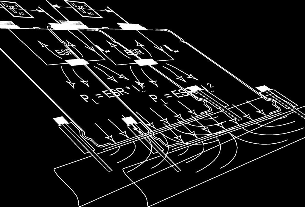
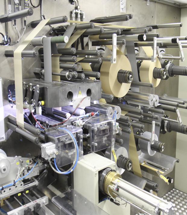
4 // Electrolytic Capacitors Aluminum Electrolytic Capacitors GENERAL INFORMATION FTCap GmbH, Fischer und Tausche Capacitors has been a manufacturer of capacitors since Many years of experience, continuous research & development and the latest state of the art production machinery guarantees products of the highest quality. ALUMINIUM ELECTROLYTIC CAPACITORS -polarized capacitors general industrial inverter telecommunications switch mode power supplies photovoltaic wind power plants medical smoothing and filtering welding and photo flash applications -non polarized capacitors audio - video applications charging capacitors for photo flash capacitor banks single phase motor starting 1. Construction of Aluminium Electrolytic Capacitors High gain etched anode foil with the thick oxide layer, which is produced by the forming-process, is shown at the top of figure 2. The cathode foil with a much thinner oxide layer is arranged at the bottom. Layers of papers are seperating both foils. The electrolyte fills up the pores of the aluminium foils and contacts the anode and cathode surface to establish the capacitance. The dielectric consists of the oxide layers of the anode foil respectively the cathode foil. This construction builds two capacitances: the anode and the cathode capacitances. Because of the thicker oxide layer the anode capacitance is normally much smaller than the cathode capacitance. Fig. 1 shows the construction of a typical electrolytic capacitor 1 terminal 2 aluminium can 3 insulation 4 bottom insulation 5 deck 6 sealing 7 safety vent 8 tab foil 9 winding 4
. If C A << C K it follows C G C A.")


5 // Electrolytic Capacitors Aluminum Electrolytic Capacitors Fig.2 shows a cross section of the winding. If two capacitors are connected in series, the total capacitance results from the relationship C G =C A *C K /(C A +C K ). If C A << C K it follows C G C A. ( aspired normal case) This means the anode capacitance determines the capacitance of the whole capacitor ( the cathode foil sligthly decreases the capacitance). To accomplish that, highly etched cathode foils are necessary. Nonpolarized electrolytic capacitors use the same foil for anode and cathode ( C A = C K ) Therefore the capacitance of these capacitors are given by C G = 0,5 * C A. It is obvious that a nonpolarized electrolytic capacitor needs two times the space of a polarized capacitor. 2. Different types of foil etched and formed surface solid aluminium core high- anode foil etched and formed surface solid aluminium core low- anode foil etched surface solid aluminium core cathode foil 5
6 // Electrolytic Capacitors Aluminum Electrolytic Capacitors 3. Parameter 3.1. The rated ( ) is the the capacitor is designed for. This may be applied continously to the capacitor over the full temperature range Surge The Surge may be applied to the capacitors only for a short time. 315 V : U S =1,15 * ( 5 times 1 min per hour) > 315 V : U S =1,1 * ( 5 times 1 min per hour) 3.3. In many applications the applied to capacitors is a combination of direct and alternating. Pay attention to the following points: The superposition of AC and DC must not exceed the rated. Reverse is not allowed. The applied ripple current must not exceed the rated ripple current Maximum reverse The Aluminium Electrolytic Capacitor is a polar component. Diodes with a max. conducting state of 0.8 V could be used to prevent reverse polarity. Single short time reverse polarity of V < 1.5 V for t < 1 s is tolerated capacitance The rated capacitance is usually determined at 100 Hz and 20 C. In general the rated capacitance is marked on the capacitor in µf DC and AC capacitance The capacitance determined by AC measurements is smaller than the capacitance determined by charge / discharge measurements. In most applications the capacitor is applied to an alternating so in general the capacitance is measured with the AC method Capacitance vs temperature and frequency The capacitance varies with temperature and frequency The capacitance increases with increasing temperature The capacitance decreases with increasing frequency The following diagrams illustrate these interdependent realtionships: 6
7 // Electrolytic Capacitors Aluminum Electrolytic Capacitors 3.8. ESR The equivalent series resistance represents the losses of a capacitor (the resistance of the foil, electrolyte, terminals). The ESR depends on frequency and temperature ESL The equivalent series inductance represents the inductive part of the capacitor (leads, foil). The ESL depends mainly on the frequency Dissipation factor tan δ (DF) The dissipation factor is defined as the power loss of the capacitor divided by the reactive power of the capacitor. tan δ = ESR *ω*c S In general the DF is measured at 100 Hz and 20 C Impedance Z The impedance of the capacitor is given by the ESR, ESL and the capacitance. The impedance depends on the temperature and the frequency. The impedance is normally measured at 10 khz. 4. Mounting Position for screw terminal capacitors Upright position is recommended to prevent electrolyte leakage in case of vent opening. Horizontal mounting is also possible but the vent must faces upwards. Terminals / Mounting stud These maximum torque values should not be exceed: Screw thread Maximum torque in Nm M4 2,0 M5 2,0 M6 2,5 M8 4,0 M12 10,0 7
8 // Electrolytic Capacitors Aluminum Electrolytic Capacitors 5. Thermal Model 8
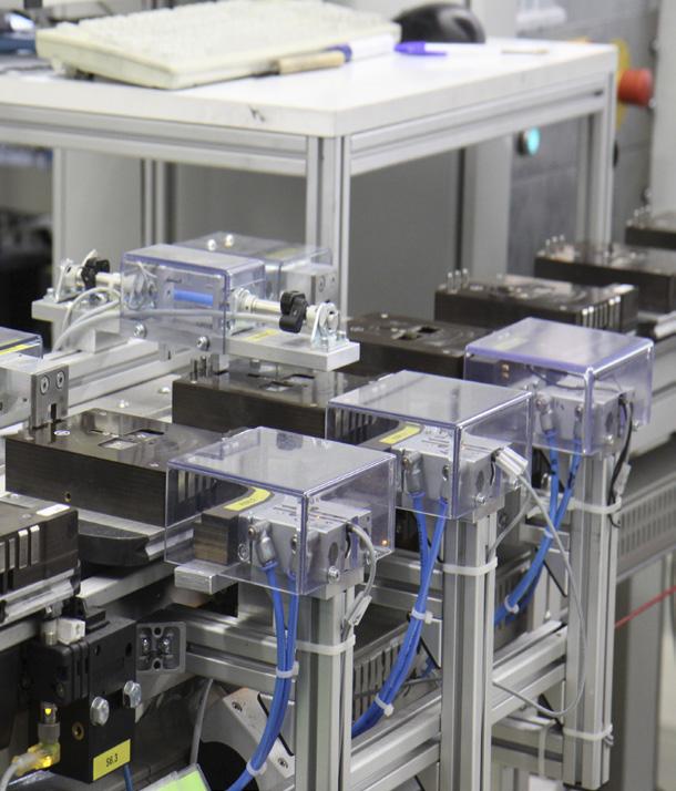
9 // Electrolytic Capacitors Aluminum Electrolytic Capacitors 6. Quality 6.1. Certification Quality is the main reason of our success. Without ignoring the importance of price of course, customers choose and remain with to satisfy their needs for top quality capacitors. It is therefore our pledge to continue producing and delivering top quality capacitors as efficiently as possible. In addition to our commitment to quality, we are also committed to a healthy environment. That is why each and every one of our employees, from top management down to the workshop, accepts his or her environmental responsibilities and strives to work as effectively and efficiently as possible. Intermediate testing is carried out through the entire production process in addition to the 100% final testing of each capacitor before shipment. All of our employees know that quality is the top priority for our customers. Workers participate in the process of continued improvement, quite often by anticipating. The result is uninterrupted flow production. Fischer & Tausche Capacitors are certified 9001:2008. The company certificate is available on the website. 7. Safety Precautions 7.1. Charged Capacitors Electrolytic capacitors may store high amounts of energy (especially photo flash and high capacitors). To avoid electrical shocks and sparks always discharge electrolytic capacitors before handling. For higher it is recommended to shorten the terminals during handling Danger of use and abuse Explosions of electrolytic capacitors may occur if the capacitor is exposed to reverse above specified limit above specified limit ripple currents above specified limit ambient temperatures above specified limit high mechanical impact 7.3. Operating electrolytes Principally operating electrolytes used in products do not contain dangerous substances. However, in rare exceptional cases it is necessary to use certain substances to achieve certain physical chemical or electrical properties. In these cases the concentration is reduced to an absolute minimum. Generally the following safety hints should be respected using operating electrolytes: Avoid skin and eye contact. Should the electrolyte come into contact with skin, immediately rinse with abundant amounts of fresh water Eyes must be rinsed at least 15 min under flowing cold water. Consult your doctor immediately with complaints. Inhaling electrolyte steams or vapors must be avoided. Work area must be well ventilated. Clothes coming into contact with electrolyte should be washed and cleaned ROHS All products are fully compliant with the RoHS Directive 2005/618/EC Disposal Aluminium Electrolytic Capacitors can be disposed or recycled. The disposal rules are governed by the national and local authorities and and have to be taken into consideration. The European Waste Code No. is

10 // Electrolytic Capacitors 85 C A 8. Ser Axial terminals Low mounting height High CV product Long life C Features All contacts welded High CV product Welded axial leads High reliability Applications HiFi Industrial Tube amplifier RoHS compliant REACH compliant Different case sizes, s and capacitance combinations are available on request. Also in small lots. General specifications Items Characteristics capacitance range 4, µf Capacitance tolerance ± 20% range Surge U S Max. reverse V 315 V: U S = 1,15 > 315 V: U S = 1,10 Category temperature range - 40 C C Leakage current I L after 5 Useful life C ; ; I R~ 2 V 0,008 * * + 6 µa [µa] Requirements Δ C/C 30 % of initial value ESR 300 % of specified limit I L specified limit Endurance test C, Δ C/C 20 % of initial value ESR 130 % of specified limit Requirements I L specified limit Climatic category IEC /085/56 Voltage proof of the external insulation D 25 mm: 1000 V AC D > 25 mm: 2500 V AC Sectional specification IEC Ø leads Up to 25 mm Ø : 0,8 mm ; more than 25 mm Ø : 1,0 mm 10
11 // Electrolytic Capacitors 85 C A Electrical data and ordering code for series A cap. D x L [mm] Typ. ESR current 85 C [A] A... cap. D x L [mm] Typ. ESR current 85 C [A] A x , x , x , x , x , x , x , x , x , x , x , x50 9 6, x50 8 7, x66 6 9, x , x , x , x , x , x , x , x , x , x , x , x , x , x , x , x , x , x , x , x , x , x , x , x , x , x , x , x , x , x , x , x , x , x , x , x , x , x , x , x , x , x , x , x , x , x , x , x , x , x , x , x , x , x , x , x , x , x , x , x , x , x , x , x , x , x , x , x , x , x , x , x , x , x , x , x , x , x ,
12 // Electrolytic Capacitors 85 C A cap. D x L [mm] Typ. ESR current 85 C [A] A... cap. D x L [mm] Typ. ESR current 85 C [A] A x , x , x , x , x , x , x , x , x , x , x , x , x , x , x , x , x , x , x , x , x , x , x , x , x , x , x , x , x , x , x , x , x , x , x , x , x , x , x , x , x , x , x , x , x , x , x , x , x , x , x , x , x , x , x , x , x , x , x , x , x , x , x , ,7 10x ,1 4, ,8 10x ,1 6, x , x , x , x , x , x , x , x , x , x , x , x , x ,
13 // Electrolytic Capacitors 85 C A 13
14 // Electrolytic Capacitors 105 C AH Axial terminals Low mounting height High CV product Long life C Features All contacts welded High ripple current Welded axial leads High reliability Applications HiFi Industrial Telecommunications RoHS compliant REACH compliant Different case sizes, s and capacitance combinations are available on request. Also in small lots. General specifications Items Characteristics capacitance range µf Capacitance tolerance ± 20% range Surge U S Max. reverse V 315 V: U S = 1,15 > 315 V: U S = 1,10 2 V Category temperature range - 40 C C Leakage current I L after 5 Useful life C ; ; I R~ 0,008 * * + 6 µa [µa] Requirements Δ C/C 30 % of initial value ESR 300 % of specified limit I L specified limit Endurance test C, Δ C/C 20 % of initial value ESR 130 % of specified limit Requirements I L specified limit Climatic category IEC /105/56 Voltage proof of the external insulation D 25 mm: 1000 V AC D > 25 mm: 2500 V AC Sectional specification IEC Ø leads Up to 25 mm Ø : 0,8 mm ; more than 25 mm Ø : 1,0 mm 14
15 // Electrolytic Capacitors 105 C AH Electrical data and ordering code for series AH cap. Typ. ESR current cap. Typ. ESR current 105 C [A] AH C [A] AH x , x , x , x , x , x , x , x , x , x , x , x50 9 6, x50 8 7, x66 6 9, x , x , x , x , x , x , x , x , x , x , x , x , x , x , x , x , x , x , x , x , x , x , x , x , x , x , x , x , x , x , x , x , x , x , x , x , x , x , x , x , x , x , x , x , x , x , x , x , x , x , x , x , x , x , x , x , x , x , x , x , x , x , x , x , x , x , x , x , x , x , x , x , x , x , x , x , x , x ,
16 // Electrolytic Capacitors 105 C AH cap. Typ. ESR current cap. Typ. ESR current 105 C [A] AH C [A] AH x , x , x , x , x , x , x , x , x , x , x , x , x , x , x , x , x , x , x , x , x , x , x , x , x , x , x , x , x , x , x , x , x , x , x , x , x , x , x , x , x , x , x , x , x , x , x , x , x , x , x , x , x , x , x , x , x , x , x , x , x , x , x , x ,
17 // Electrolytic Capacitors 105 C AH 17
18 // Electrolytic Capacitors 125 C AG Axial terminals Low mounting height High CV product Long life C 1. Low temperature 55 C Features All contacts welded High temp 125 C Long useful life Applications Automotive Inverter/drives Laser Industrial RoHS compliant REACH compliant Different case sizes, s and capacitance combinations are available on request. Also in small lots. General specifications Items Characteristics capacitance range µf Capacitance tolerance ± 20% range Surge U S Max. reverse V U S = 1,15 Category temperature range - 55 C C Leakage current I L after 5 Useful life Endurance test C ; ; I R~ C, 2 V 0,004 * * + 6 µa [µa] Requirements Δ C/C 30 % of initial value ESR 300 % of specified limit I L specified limit Requirements Δ C/C 20 % of initial value ESR 130 % of specified limit I L specified limit Climatic category IEC /125/56 Voltage proof of the external insulation D 25 mm: 1000 V AC D > 25 mm: 2500 V AC Sectional specification IEC Ø leads Up to 25 mm Ø : 0,8 mm ; more than 25 mm Ø : 1,0 mm 18
19 // Electrolytic Capacitors 125 C AG Electrical data and ordering code for series AG cap. Typ. ESR current D x L [mm] 125 C [A] AG x , x , x , x , x , x , x , x , x , x , x , x , x , x , x , x , x , x , x , x , cap. D x L [mm] Typ. ESR current 125 C [A] AG x , x , x , x , x , x , x , x , x , x , x , x , x , x , x , x , x , x , x , x ,
20 // Electrolytic Capacitors 85 C ATBI Axial terminals Bipolar construction For crossover networks Features All contacts welded Bipolar Applications HiFi Consumer RoHS compliant REACH compliant Different case sizes, s and capacitance combinations are available on request. Also in small lots. General specifications Items capacitance range Capacitance tolerance bipolar (rated DC) Max. peak (AC) Characteristics khz ± 20%; ± 10% on request 63 V 23 V ac 100 V 35 V ac May not exceed rated (DC) Category temperature range - 40 C C Useful life > C > 1000 C Endurance test C Requirements Δ C/C 30 % of initial value ESR 300 % of specified limit I L specified limit Requirements Δ C/C 20 % of initial value ESR 130 % of specified limit I L specified limit Climatic category IEC /085/56 Voltage proof of the external insulation D 25 mm: 1000 V AC D > 25 mm: 2500 V AC Ø leads Up to 25 mm Ø : 0,8 mm ; more than 25 mm Ø : 1,0 mm 20
21 // Electrolytic Capacitors 85 C ATBI Electrical data and ordering code for series ATBI capacitance (other values available on request) Hz Hz ATBI... 1,0 10x20 1, ,2 10x20 2, ,3 10x20 3, ,7 10x20 4, ,8 10x20 6, x x x x x x x x x x x x x x ,0 10x20 1, ,2 10x30 2, ,3 10x30 3, ,7 10x30 4, ,8 10x30 6, x x x x x x x x
22 // Electrolytic Capacitors 85 C ATBIG Axial terminals Bipolar construction Plain foil For crossover networks Features All contacts welded Bipolar Applications HiFi Consumer RoHS compliant REACH compliant Different case sizes, s and capacitance combinations are available on request. Also in small lots. General specifications Items capacitance range Capacitance tolerance Characteristics khz ± 10%; ± 5% on request 35 V 23 V ac bipolar (rated DC) 50 V 35 V ac 70V 50 V ac Max. peak (AC) May not exceed rated (DC) Category temperature range - 40 C C Useful life > C > 1000 C Endurance test C Requirements Δ C/C 30 % of initial value ESR 300 % of specified limit I L specified limit Requirements Δ C/C 20 % of initial value ESR 130 % of specified limit I L specified limit Climatic category IEC /085/56 Voltage proof of the external insulation D 25 mm: 1000 V AC D > 25 mm: 2500 V AC Ø leads Up to 25 mm Ø : 0,8 mm ; more than 25 mm Ø : 1,0 mm 22
23 // Electrolytic Capacitors 85 C ATBIG Electrical data and ordering code for series ATBIG capacitance (other values available on request) ATBIG Hz Hz Hz 1,0 10x20 1, ,2 10x30 2, ,3 10x30 3, ,7 10x30 4, ,8 10x30 6, x x x x x x x x x x ,0 10x20 1, ,2 10x30 2, ,3 10x30 3, ,7 12x30 4, ,8 12x30 6, x x x x x x x x x x x25 1, ,2 10x30 2, ,3 10x30 3, ,7 12x30 4, ,8 14x30 6, x x x x x x x
24 // Electrolytic Capacitors 85 C GM Screw terminals High CV product Long life C Features All internal contact welded High capacitance High CV product Low inductance ESL Applications Computer Inverter/drives Traction Welding RoHS compliant REACH compliant Different case sizes, s and capacitance combinations are available on request. Also in small lots. General specifications Items Characteristics capacitance range µf Capacitance tolerance ± 20% range V Surge U S 315 V: U S = 1,15 > 315 V: U S = 1,10 Max. reverse / ESL 2 V / 20 nh Category temperature range - 40 C C Leakage current I L after 5 Useful life C ; ; I R~ 0,008 * * + 6 µa [µa] Requirements Δ C/C 30 % of initial value ESR 300 % of specified limit I L specified limit Endurance test C, Δ C/C 20 % of initial value ESR 130 % of specified limit Requirements I L specified limit Climatic category IEC /085/56 Voltage proof of the external insulation 2500 V AC Sectional specification IEC
25 // Electrolytic Capacitors 85 C GM Drawings for series GMA and GMB Fig1: GMA for ring clamp mounting Fig 2: GMB for stud mounting Dimensions and mechanical data dimensions, case with insulation sleeve connecting terminals mounting stud, GMB only D case length L h a thread max. torque B max. torque available in 5 mm [mm] [mm] [mm] [mm] [Nm] [Nm] M 5 2,0 M 8 x 12 4, M 5 2,0 M 8 x 12 4, M 5 2,0 M 12 x 16 10, ,5 M 5 2,0 M 12 x 16 10, ,7 M 5, M 6 2,0 ; 2,5 M 12 x 16 10, ,7 M 6 2,5 M 12 x 16 10,0 Remarks GMA : connecting screws M 5 or M 6 GMB : connecting screws M 5 or M 6 + mounting nut M 8 or M 12 Further mounting accessories like clamps, nylon cup nuts and insulation disks on request, see accessory equipment 25
26 // Electrolytic Capacitors 85 C GM Electrical data and ordering code for series GM cap. D x L [mm] Typ. ESR 100 Hz, current 85 C [A] Plain base: GMA Stud mounting: GMB cap. Typ. ESR 100 Hz, current 85 C [A] Plain base: GMA Stud mounting: GMB x55 6 9, x , x , x , x , x , x , x , x , x , x , x , x , x , x , x , x , x , x , x , x , x , x , x , x , x , x70 9 7, x55 9 7, x80 8 9, x70 7 9, x , x , x , x , x , x , x , x , x , x , x , x , x , x , x , x , x , x , x , x , x , x , x , x , x , x , x , x , x , x , x , x , x , x , x , x , x , x , x , x , x , x , x , x , x , x , x , x , x , x , x , x , x , x , x , x80 9 9, x , x , x , x , x , x , x , x ,
27 // Electrolytic Capacitors 85 C GM cap. Typ. ESR 100 Hz, current 85 C [A] Plain base: GMA Stud mounting: GMB cap. Typ. ESR 100 Hz, current 85 C [A] Plain base: GMA Stud mounting: GMB x , x , x , x , x , x , x , x , x , x , x , x , x , x , x , x , x , x , x , x , x , x , x , x , x , x , x , x , x , x , x , x , x , x , x , x , x , x , x , x , x , x , x , x , x , x , x , x , x , x , x , x , x , x , x , x , x , x , x , x , x , x , x , x , x , x , x , x , x , x , x , x , x , x , x , x , x , x , x , x , x , x , x , x , x , x , x , x , x , x , x , x , x , x , x , x , x , x ,
28 // Electrolytic Capacitors 85 C GM cap. Typ. ESR 100 Hz, current 85 C [A] Plain base: GMA Stud mounting: GMB cap. Typ. ESR 100 Hz, current 85 C [A] Plain base: GMA Stud mounting: GMB x , x , x , x , x , x , x , x , x , x , x , x , x , x , x , x , x , x , x , x , x , x , x , x , x , x , x , x , x , x , x , x , x , x , x , x , x , x , x , x , x , x , x , x , x , x , x , x , x , x , x , x , x , x , x , x , x , x , x , x , x , x , x , x , x , x , x , x , x , x , x , x , x , x , x , x , x , x , x , x , x , x , x , x , x , x , x , x , x , x , x , x , x , x , x , x , x , x ,
29 // Electrolytic Capacitors 85 C GM 500 cap. D x L [mm] Typ. ESR 100 Hz, current 85 C [A] Plain base: GMA Stud mounting: GMB x , x , x , x , x , x , x , x , x , x ,
30 // Electrolytic Capacitors 85 C GMX Screw terminals High CV product Long life C 1. Features All internal contact welded High capacitance High CV product Long useful life Applications Computer Industrial Inverter/drives Laser RoHS compliant REACH compliant Different case sizes, s and capacitance combinations are available on request. Also in small lots. General specifications Items Characteristics capacitance range µf Capacitance tolerance ± 20% range V Surge U S 315 V: U S = 1,15 > 315 V: U S = 1,10 Max. reverse / ESL 2 V / 20 nh Category temperature range - 40 C C Leakage current I L after 5 Useful life C ; ; I R~ 0,008 * * + 6 µa [µa] Requirements Δ C/C 30 % of initial value ESR 300 % of specified limit I L specified limit Endurance test C, Δ C/C 20 % of initial value ESR 130 % of specified limit Requirements I L specified limit Climatic category IEC /085/56 Voltage proof of the external insulation 2500 V AC Sectional specification IEC
31 // Electrolytic Capacitors 85 C GMX Drawings for series GMXA and GMXB Fig1: GMXA for ring clamp mounting Fig 2: GMXB for stud mounting Dimensions and mechanical data Dimensions, case with insulation sleeve Connecting terminals Mounting stud, GMXB only D Case length L available h a Thread Max. torque B Max. torque in 5 mm [mm] [mm] [mm] [mm] [Nm] [Nm] M 5 2,0 M 8 x 12 4, M 5 2,0 M 8 x 12 4, M 5 2,0 M 12 x 16 10, ,5 M 5 2,0 M 12 x 16 10, ,7 M 5, M 6 2,0 ; 2,5 M 12 x 16 10, ,7 M 6 2,5 M 12 x 16 10,0 GMXA : connecting screws M 5 or M 6 GMXB : connecting screws M 5 or M 6 + mounting nut M 8 or M 12 Remarks Further mounting accessories like clamps, nylon cup nuts and insulation disks on request, see accessory equipment 31
32 // Electrolytic Capacitors 85 C GMX Electrical data and ordering code for series GMX cap. Typ. ESR 100 Hz, current 85 C [A] Plain base: GMXA Stud mounting: GMXB cap. Typ. ESR 100 Hz, current 85 C [A] Plain base: GMXA Stud mounting: GMXB x55 6 9, x , x , x , x , x , x , x , x , x , x , x , x , x , x , x , x , x , x , x , x , x , x , x , x , x , x , x , x , x70 9 7, x , x80 8 9, x70 8 8, x , x , x , x , x , x , x , x , x , x , x , x , x , x , x , x , x , x , x , x , x , x , x , x , x , x , x , x80 8 9, x , x , x , x , x , x , x , x , x , x , x , x , x , x , x , x , x , x , x , x , x , x , x , x , x , x , x , x , x , x , x , x , x ,
33 // Electrolytic Capacitors 85 C GMX cap. Typ. ESR 100 Hz, current 85 C [A] Plain base: GMXA Stud mounting: GMXB cap. Typ. ESR 100 Hz, current 85 C [A] Plain base: GMXA Stud mounting: GMXB x , x , x , x , x , x , x , x , x , x , x , x , x , x , x , x , x , x , x , x , x , x , x , x , x , x , x , x , x , x , x , x , x , x , x , x , x , x , x , x , x , x , x , x , x , x , x , x , x , x , x , x , x , x , x , x , x , x , x , x , x , x , x , x , x , x , x , x , x , x , x , x , x , x , x , x , x , x , x , x , x , x , x , x , x , x , x , x , x , x , x , x , x , x , x , x , x , x ,
34 // Electrolytic Capacitors 85 C GMX cap. Typ. ESR 100 Hz, current 85 C [A] Plain base: GMXA Stud mounting: GMXB cap. D x L [mm] Typ. ESR 100 Hz, current 85 C [A] Plain base: GMXA Stud mounting: GMXB x , x , x , x , x , x , x , x , x , x , x , x , x , x , x , x , x , x , x , x , x , x , x , x , x , x , x , x , x , x , x , x , x , x , x , x , x , x , x , x , x , x , x , x , x , x , x , x , x , x , x , x , x , x , x , x , x , x , x , x , x , x , x , x , x , x , x , x , x , x , x , x , x , x , x , x , x , x , x , x , x , x , x , x , x , x ,
35 // Electrolytic Capacitors 85 C GMX 35
36 // Electrolytic Capacitors 105 C G Screw terminals High CV product Long life Features All internal contact welded High performance High ripple current Long useful life Applications Industrial Inverter/drives Telecommunications Laser General specifications RoHS compliant REACH compliant Different case sizes, s and capacitance combinations are available on request. Also in small lots. Items Characteristics capacitance range µf Capacitance tolerance ± 20% range V Surge U S 315 V: U S = 1,15 > 315 V: U S = 1,10 Max. reverse / ESL 2 V / 20 nh Category temperature range - 40 C C Leakage current I L after 5 Useful life C ; ; I R~ 0,008 * * + 6 µa [µa] Requirements Δ C/C 30 % of initial value ESR 300 % of specified limit I L specified limit Endurance test C, Δ C/C 20 % of initial value ESR 130 % of specified limit Requirements I L specified limit Climatic category IEC /105/56 Voltage proof of the external insulation 2500 V AC Sectional specification IEC
37 // Electrolytic Capacitors 105 C G Drawings for series GA and GB Fig1: GA for ring clamp mounting Fig 2: GB for stud mounting Dimensions and mechanical data Dimensions, case with insulation sleeve Connecting terminals Mounting stud, GB only D Case length l available h a Thread Max. torque B Max. torque in 5 mm [mm] [mm] [mm] [mm] [Nm] [Nm] M 5 2,0 M 8 x 12 4, M 5 2,0 M 8 x 12 4, M 5 2,0 M 12 x 16 10, ,5 M 5 2,0 M 12 x 16 10, ,7 M 5, M 6 2,0 ; 2,5 M 12 x 16 10, ,7 M 6 2,5 M 12 x 16 10,0 Remarks GA : connecting screws M 5 or M 6 GB : connecting screws M 5 or M 6 + mounting nut M 8 or M 12 Further mounting accessories like clamps, nylon cup nuts and insulation disks on request, see accessory equipment 37
38 // Electrolytic Capacitors 105 C G Electrical data and ordering code for series G cap. D x L [mm] Typ. ESR 100 Hz, current 105 C [A] Plain base: GA Stud mounting: GB cap. Typ. ESR 100 Hz, current 105 C [A] Plain base: GA Stud mounting: GB x55 6 9, x , x , x , x , x , x , x , x , x , x , x , x , x , x , x , x , x , x , x , x , x , x , x , x , x , x , x , x , x70 9 7, x , x80 8 9, x70 8 8, x , x , x , x , x , x , x , x , x , x , x , x , x , x , x , x , x , x , x , x , x , x , x , x , x , x , x , x80 8 9, x , x , x , x , x , x , x , x , x , x , x , x , x , x , x , x , x , x , x , x , x , x , x , x , x , x , x , x , x , x , x , x , x ,
39 // Electrolytic Capacitors 105 C G cap. Typ. ESR 100 Hz, current 105 C [A] Plain base: GA Stud mounting: GB cap. Typ. ESR 100 Hz, current 105 C [A] Plain base: GA Stud mounting: GB x , x , x , x , x , x , x , x , x , x , x , x , x , x , x , x , x , x , x , x , x , x , x , x , x , x , x , x , x , x , x , x , x , x , x , x , x , x , x , x , x , x , x , x , x , x , x , x , x , x , x , x , x , x , x , x , x , x , x , x , x , x , x , x , x , x , x , x , x , x , x , x , x , x , x , x , x , x , x , x , x , x , x , x , x , x , x , x , x , x , x , x , x , x , x , x , x , x ,
40 // Electrolytic Capacitors 105 C G cap. Typ. ESR 100 Hz, current 105 C [A] Plain base: GA Stud mounting: GB cap. Typ. ESR 100 Hz, current 105 C [A] Plain base: GA Stud mounting: GB x , x , x , x , x , x , x , x , x , x , x , x , x , x , x , x , x , x , x , x , x , x , x , x , x , x , x , x , x , x , x , x , x , x , x , x , x , x , x , x , x , x , x , x , x , x , x , x , x , x , x , x , x , x , x , x , x , x , x , x , x , x , x , x , x , x , x , x , x , x , x , x , x , x , x , x , x , x , x , x , x , x , x , x , x , x ,
41 // Electrolytic Capacitors 105 C G 41
42 // Electrolytic Capacitors 125 C GG Screw terminals Very long lifetime High CV product High-temp 125 C Low inductance ESL Features All internal contact welded High temp 125 C Long useful life Low inductance ESL Applications Computer Industrial Inverter/drives Welding Low temperature 55 C RoHS compliant REACH compliant Different case sizes, s and capacitance combinations are available on request. Also in small lots. General specifications Items Characteristics capacitance range µf Capacitance tolerance ±20 % range V Surge U S Max. reverse / ESL U S = 1,15 2 V / 13 nh Category temperature range - 55 C C Leakage current I L after 5 Useful life C ; ; I R~ 0,008 * * + 6 µa [µa] Requirements Δ C/C 30 % of initial value ESR 300 % of specified limit I L specified limit Endurance test C, Δ C/C 20 of initial value ESR 130 % of specified limit Requirements I L specified limit Climatic category IEC /125/56 Voltage proof of the external insulation 2500 V AC Sectional specification IEC
43 // Electrolytic Capacitors 125 C GG Electrical data and ordering code for series GG cap. Typ. ESR current 125 C [A] Plain base: GGA Stud mounting: GGB cap. Typ. ESR current 125 C [A] Plain base: GGA Stud mounting: GGB x , x , x , x , x70 9 7, x , x80 8 9, x , x70 8 8, x , x , x , x70 7 9, x , x , x , x , x , x , x , x , x , x , x , x , x , x , x70 9 8, x , x80 8 9, x , x , x , x , x , x , x , x , x , x , x , x , x , x , x , x , x , x , x , x , x , x ,

44 // Electrolytic Capacitors Special electrolyte 85 C GF Non flammable electrolyte Screw terminals High CV product Long life CGF Features All internal contact welded Self distinguishing electrolyte High capacitance High reliability Applications Industrial Inverter/drives Professional photoflash Welding RoHS compliant REACH compliant Different case sizes, s and capacitance combinations are available on request. Also in small lots. General specifications Items Characteristics capacitance range µf Capacitance tolerance ± 20% range V Surge U S U S = 1,10 Max. reverse / ESL 2 V / 20 nh Category temperature range - 25 C C Leakage current I L after 5 Useful life C ; ; I R~ 0,008 * * + 6 µa [µa] Requirements Δ C/C 30 % of initial value ESR 300 % of specified limit I L /specified limit Endurance test C, Δ C/C 20 % of initial value ESR 130 % of specified limit Requirements I L specified limit Climatic category IEC /085/56 Voltage proof of the external insulation 2500 V AC Sectional specification IEC
45 // Electrolytic Capacitors Special electrolyte 85 C GF Drawings for series GFA and GFB Fig1: GFA for ring clamp mounting Fig 2: GFB for stud mounting Dimensions and mechanical data Dimensions, case with insulation sleeve Connecting terminals Mounting stud, GFB only D h a Thread Max. torque B Max. torque [mm] [mm] [mm] [Nm] [Nm] M 5 2,0 M 8 x 12 4, M 5 2,0 M 8 x 12 4, M 5 2,0 M 12 x 16 10, ,5 M 5 2,0 M 12 x 16 10, ,7 M 5, M 6 2,0 ; 2,5 M 12 x 16 10, ,7 M 6 2,5 M 12 x 16 10,0 Remarks GFA : connecting screws M 5 or M 6 GFB : connecting screws M 5 or M 6 + mounting nut M 8 or M 12 Further mounting accessories like clamps, nylon cup nuts and insulation disks on request, see accessory equipment 45
46 // Electrolytic Capacitors Special electrolyte 85 C GF Electrical data and ordering code for series GF cap. Typ. ESR current 85 C [A] Plain base: GFA Stud mounting: GFB cap. Typ. ESR current 85 C [A] Plain base: GFA Stud mounting: GFB x , x , x , x , x , x , x , x , x , x , x , x , x , x , x , x , x , x , x , x , x , x , x , x , x , x , x , x , x , x , x , x , x , x , x , x , x , x , x , x , x , x , x , x , x , x ,
47 // Electrolytic Capacitors Special electrolyte 85 C GF 47


48 // Electrolytic Capacitors 105 C GW Screw terminals High performance Ultra low inductance Heat sink mounting! Very high ripple current Features All contacts welded High ripple current Thermal conducting pad Best suited for heatsink mounting Applications Inverter/drives Traction Industrial Welding RoHS compliant REACH compliant Different case sizes, s and capacitance combinations are available on request. Also in small lots. General specifications Item Characteristics capacitance range µf Capacitance tolerance ± 20% range V Surge U S 315 V: U S = 1,15 > 315 V: U S = 1,10 Max. reverse / ESL 2 V / 13 nh Category temperature range - 40 C C Leakage current I L after 5 0,008 * * + 6 µa [µa] Useful life C ; ; I R~ Δ C/C 30 % of initial value ESR 300 % of specified limit Requirements I L specified limit Endurance test C, Δ C/C 20 % of initial value ESR 130 % of specified limit Requirements I L specified limit Climatic category IEC /105/56 Voltage proof of the external insulation 2500 V AC Sectional specification IEC
49 // Electrolytic Capacitors 105 C GW Drawings for series GW Fig1: Version GW for ring clamp mounting Dimensions and mechanical data Connecting terminals Accessories D h a x i Thread Max. torque [Nm] S 1 S ,5 20 M 5 2, ,5 20 M 5, ,7 2,0 ; 2,5 90 M ,7 4,5 20 M 6 2,5 105 GW : Connecting screws M 5 or M 6, further mounting accessories like clamps, nylon cup nuts and insulation disks on request 49
50 // Electrolytic Capacitors 105 C GW Electrical data and ordering code for series GW cap. Typ. ESR current 105 C [A] GW... cap. Typ. ESR current 105 C [A] GW x , x , x , x , x , x , x , x , x , x , x , x , x , x , x , x , x , x , x , x , x , x , x , x , x , x , x , x , x , x , x , x , x , x , x , x , x , x , x , x , x , x ,
51 For your notes... 51
52 // Electrolytic Capacitors 85 C SI Standard series SI: snap in, 2 pins SI4P: snap in, 4 pins Features All internal contact welded High CV product High reliability Long useful life Applications HiFi Computer Inverter/drives RoHS compliant REACH compliant Different case sizes, s and capacitance combinations are available on request. Also in small lots. General specifications Items Characteristics capacitance range µf Capacitance tolerance ± 20% range Surge U S Max. reverse V 315 V: U S = 1,15 > 315 V: U S = 1,10 2 V Category temperature range - 40 C C Leakage current I L after 5 Useful life C ; ; I R~ 0,008 * * + 6 µa [µa] Requirements Δ C/C 30 % of initial value ESR 300 % of specified limit I L specified limit Endurance test C, Δ C/C 20 of initial value ESR 130 % of specified limit Requirements I L specified limit Climatic category IEC /85/56 Voltage proof of the external insulation 2500 V AC Sectional specification IEC
53 // Electrolytic Capacitors 85 C SI Drawings for series SI and SI4P SI SI4P Fig 2: SI4P: keyed polarity 4 pin snap in version (here with 6,3 mm claw, the 4,5 mm claw is also available). Case diameter 35, 40, 45 mm only Mounting hole dimensions (mm) NC terminals must be soldered to isolated pads Fig 1: SI : Standard 2 pin snap in version and mounting hole dimensions (mm) Case diameter 25 to 45 mm only 53
54 // Electrolytic Capacitors 85 C SI Electrical data and ordering code for series SI cap. Typ. ESR current 85 C [A] 2 pins: SI 4 pins: SI4P... cap. Typ. ESR current 85 C [A] 2 pins: SI 4 pins: SI4P x , x , x , x , x , x , x , x , x , x , x , x , x40 9 7, x35 9 7, x45 9 7, x50 7 8, x40 7 8, x45 6 9, x , x , x , x , x , x , x , x , x , x , x , x , x , x , x , x , x , x , x , x , x , x , x , x , x , x , x , x , x , x , x , x , x , x50 8 8, x , x , x , x , x , x , x , x , x , x , x , x , x , x , x , x , x , x , x , x , x , x , x , x , x , x , x , x , x , x , x , x , x , x , x , x , x , x ,
55 // Electrolytic Capacitors 85 C SI cap. Typ. ESR current 85 C [A] 2 pins: SI 4 pins: SI4P cap. Typ. ESR current 85 C [A] 2 pins: SI 4 pins: SI4P x , x , x , x , x , x , x , x , x , x , x , x , x , x , x , x , x , x , x , x , x , x , x , x , x , x , x , x , x , x , x , x , x , x , x , x , x , x , x , x , x , x , x , x , x , x , x , x , x , x , x , x , x , x , x , x , x , x , x , x , x , x , x , x , x , x , x , x , x , x , x , x , x , x , x , x , x , x , x , x , x , x , x , x , x , x , x , x , x , x , x , x , x , x , x , x , x , x , x , x ,
56 // Electrolytic Capacitors 85 C SI cap. Typ. ESR current 85 C [A] 2 pins: SI 4 pins: SI4P... cap. Typ. ESR current 85 C [A] 2 pins: SI 4 pins: SI4P x , x , x , x , x , x , x , x , x , x , x , x , x , x , x , x , x , x , x , x , x , x , x , x , x , x , x , x , x , x , x , x , x , x , x , x , x , x , x , x , x , x , x , x , x , x , x , x , x , x , x , x , x , x , x , x , x , x , x , x , x , x , x , x , x , x , x , x , x , x , x , x , x , x , x , x , x , x , x , x , x , x , x , x , x , x , x , x , x , x , x , x , x , x ,
57 // Electrolytic Capacitors 85 C SI cap. Typ. ESR current 85 C [A] 2 pins: SI 4 pins: SI4P x , x , x , x , x , x , x , x , x , x , x , x , x , x , x , x , x , x , x , x , x , x , x , x , x , x , x , x , x , x , x , x , x , x , x , x , x , cap. Typ. ESR current 85 C [A] 2 pins: SI 4 pins: SI4P x , x , x , x , x , x , x , x , x , x , x , x , x , x , x , x , x , x , x , x , x , x , x , x , x , x , x , x , x , x , x , x , x , x , x , x ,
58 // Electrolytic Capacitors 85 C SI 58
59 For your notes... 59
60 // Electrolytic Capacitors 105 C SIH Ultra compact design Long life time SIH: snap in, 2 pins SI4PH: snap in, 4 pins Features All internal contact welded High CV product High reliability Ultra compact Applications HiFi Computer Industrial Tube amplifier RoHS compliant REACH compliant Different case sizes, s and capacitance combinations are available on request. Also in small lots. General specifications Items Characteristics capacitance range µf Capacitance tolerance ± 20% range Surge U S Max. reverse V 315 V: U S = 1,15 > 315 V: U S = 1,10 2 V Category temperature range - 40 C C Leakage current I L after 5 Useful life C ; ; I R~ 0,008 * * + 6 µa [µa] Requirements Δ C/C 30 % of initial value ESR 300 % of specified limit I L specified limit Endurance test C, Δ C/C 20 of initial value ESR 130 % of specified limit Requirements I L specified limit Climatic category IEC /105/56 Voltage proof of the external insulation 2500 V AC Sectional specification IEC
61 // Electrolytic Capacitors 105 C SIH Drawings for series SIH and SI4PH SIH SI4PH Fig 2: SI4PG: keyed polarity 4 pin snap in version (here with 6,3 mm claw, the 4,5 mm claw is also available). Case diameter 35, 40, 45 mm only Fig 1: SIG : Standard 2 pin snap in version and mounting hole dimensions (mm) Case diameter 25 to 45 mm only Mounting hole dimensions (mm) NC terminals must be soldered to isolated pads 61
62 // Electrolytic Capacitors 105 C SIH Electrical data and ordering code for series SIH cap. Typ. ESR current 105 C [A] 2 pins: SIH 4 pins: SI4PH cap. Typ. ESR current 105 C [A] 2 pins: SIH 4 pins: SI4PH x , x , x , x , x , x , x , x , x , x , x , x , x , x , x , x , x , x , x , x , x , x , x50 9 8, x , x , x , x , x , x , x , x , x , x , x , x , x , x , x , x , x , x , x , x , x , x , x , x , x , x , x , x , x , x , x , x , x60 8 9, x , x , x , x , x , x , x , x , x , x , x , x , x , x , x , x , x , x , x , x , x , x , x , x , x , x , x , x , x , x , x , x , x , x , x , x , x , x , x , x ,
63 // Electrolytic Capacitors 105 C SIH cap. Typ. ESR current 105 C [A] 2 pins: SIH 4 pins: SI4PH cap. Typ. ESR current 105 C [A] 2 pins: SIH 4 pins: SI4PH x , x , x , x , x , x , x , x , x , x , x , x , x , x , x , x , x , x , x , x , x , x , x , x , x , x , x , x , x , x , x , x , x , x , x , x , x , x , x , x , x , x , x , x , x , x , x , x , x , x , x , x , x , x , x , x , x , x , x , x , x , x , x , x , x , x , x , x , x , x , x , x , x , x , x , x , x , x , x , x , x , x , x , x , x , x , x , x , x , x , x , x , x , x , x , x , x , x , x , x ,
64 // Electrolytic Capacitors 105 C SIH cap. Typ. ESR current 105 C [A] 2 pins: SIH 4 pins: SI4PH cap. Typ. ESR current 105 C [A] 2 pins: SIH 4 pins: SI4PH x , x , x , x , x , x , x , x , x , x , x , x , x , x , x , x , x , x , x , x , x , x , x , x , x , x , x , x , x , x , x , x , x , x , x , x , x , x , x , x , x , x , x , x , x , x , x , x , x , x , x , x , x , x , x , x , x , x , x , x , x , x , x , x , x , x , x , x , x , x , x , x , x , x , x , x , x , x , x , x , x , x , x , x , x , x , x , x , x , x , x , x , x , x , x , x , x , x , x , x ,
65 // Electrolytic Capacitors 105 C SIH cap. Typ. ESR current 105 C [A] 2 pins: SIH 4 pins: SI4PH cap. Typ. ESR current 105 C [A] 2 pins: SIH 4 pins: SI4PH x , x , x , x , x , x , x , x , x , x , x , x , x , x , x , x , x , x , x , x , x , x , x , x , x , x , x , x , x , x ,

66 // Electrolytic Capacitors 125 C SIG High reliabilty Long lifetime at 125 C SIG: snap in, 2 pins SI4PG: snap in, 4 pins Features All internal contact welded High temp 125 C High CV product High performance Low temperature Applications Automotive Consumer Industrial Tube amplifier RoHS compliant REACH compliant Different case sizes, s and capacitance combinations are available on request. Also in small lots. General specifications Items Characteristics capacitance range µf Capacitance tolerance ± 20% range Surge U S V U S = 1,15 Max. reverse Category temperature range - 55 C C Leakage current I L after 5 2 V 0,006 * * + 6 µa [µa] Useful life C ; ; I R~ ESR 300 % of specified limit Δ C/C 30 % of initial value I L specified limit Endurance test C, ESR 130 % of specified limit Δ C/C 20 % of initial value I L specified limit Climatic category IEC /125/56 Voltage proof of the external insulation 2500 V AC Sectional specification IEC
67 // Electrolytic Capacitors 125 C SIG Drawings for series SIG and SIG4P SIG SI4PG Fig 2: SI4PG: keyed polarity 4 pin snap in version (here with 6,3 mm claw, the 4,5 mm claw is also available). Case diameter 35, 40, 45 mm only Fig 1: SIG : Standard 2 pin snap in version and mounting hole dimensions (mm) Case diameter 25 to 45 mm only Mounting hole dimensions (mm) NC terminals must be soldered to isolated pads 67
68 // Electrolytic Capacitors 125 C SIG Electrical data and ordering code for series SIG cap. Typ. ESR current 125 C [A] 2 pins: SIG 4 pins: SI4PG cap. Typ. ESR current 125 C [A] 2 pins: SIG 4 pins: SI4PG x , x , x , x , x , x , x , x50 8 8, x , x , x , x , x , x , x , x , x , x , x , x , x50 8 9, x , x , x , x , x , x , x , x , x , x , x , x , x , x , x , x , x , x , x , x , x , x , x , x , x , x , x , x , x , x , x ,
69 // Electrolytic Capacitors 125 C SIG 69
70 // Electrolytic Capacitors 85 C GS DIN series PCB solder pins Features All internal contact welded High CV product High reliability Long useful life Applications HiFi Consumer Industrial Inverter/drives RoHS compliant REACH compliant Different case sizes, s and capacitance combinations are available on request. Also in small lots. General specifications Items Characteristics capacitance range µf Capacitance tolerance ± 20% range Surge U S Max. reverse V 315 V: U S = 1,15 > 315 V: U S = 1,10 2 V Category temperature range - 40 C C Leakage current I L after 5 Useful life C ; ; I R~ 0,008 * * + 6 µa [µa] Requirements Δ C/C 30 % of initial value ESR 300 % of specified limit I L specified limit Endurance test C, Δ C/C 20 of initial value ESR 130 % of specified limit Requirements I L specified limit Climatic category IEC /85/56 Voltage proof of the external insulation 2500 V AC Sectional specification IEC
71 // Electrolytic Capacitors 85 C GS Drawings and mounting pin layout of the series GS capacitors Fig 1: Dimensions of the series GS and mounting hole layouts for D = mm NC terminals must be soldered to isolated pad. 71
72 // Electrolytic Capacitors 85 C GS Electrical data and ordering code for series GS cap. Typ. ESR current 85 C [A] GS x , x , x , x , x , x , x , x , x40 9 7, x35 9 7, x45 9 7, x50 7 8, x40 7 8, x45 6 9, x , x , x , x , x , x , x , x , x , x , x , x , x , x , x , x , x , x , x , x , x , x , x , x , x , x , x , x , x , x50 8 8, x , x , x , x , cap. Typ. ESR current 85 C [A] GS x , x , x , x , x , x , x , x , x , x , x , x , x , x , x , x , x , x , x , x , x , x , x , x , x , x , x , x , x , x , x , x , x , x , x , x , x , x , x , x , x , x , x , x , x , x , x , x ,
73 // Electrolytic Capacitors 85 C GS cap. Typ. ESR current 85 C [A] GS... cap. Typ. ESR current 85 C [A] GS x , x , x , x , x , x , x , x , x , x , x , x , x , x , x , x , x , x , x , x , x , x , x , x , x , x , x , x , x , x , x , x , x , x , x , x , x , x , x , x , x , x , x , x , x , x , x , x , x , x , x , x , x , x , x , x , x , x , x , x , x , x , x , x , x , x , x , x , x , x , x , x , x , x , x , x , x , x , x , x , x , x , x , x , x , x , x , x , x , x , x , x , x , x , x , x , x , x , x , x ,
74 // Electrolytic Capacitors 85 C GS cap. Typ. ESR current cap. Typ. ESR current 85 C [A] GS C [A] GS x , x , x , x , x , x , x , x , x , x , x , x , x , x , x , x , x , x , x , x , x , x , x , x , x , x , x , x , x , x , x , x , x , x , x , x , x , x , x , x , x , x , x , x , x , x , x , x , x , x , x , x , x , x , x , x , x , x , x , x , x , x , x , x , x , x , x , x , x , x , x , x , x , x , x , x , x , x , x , x , x , x , x , x , x , x , x , x , x , x , x , x , x , x , x , x , x , x , x , x ,
75 // Electrolytic Capacitors 85 C GS cap. Typ. ESR current cap. Typ. ESR current C [A] GS x , x , x , x , x , x , x , C [A] GS x , x , x , x , x , x , x ,
76 // Electrolytic Capacitors 105 C GSH DIN series Ultra compact design Long life time PCB solder pins Features All internal contact welded High CV product High reliability Ultra compact Applications HiFi Computer Industrial Tube amplifier RoHS compliant REACH compliant Different case sizes, s and capacitance combinations are available on request. Also in small lots. General specifications Items Characteristics capacitance range µf Capacitance tolerance ± 20% range V Surge U S Max. reverse 315 V: U S = 1,15 > 315 V: U S = 1,10 Category temperature range - 40 C C Leakage current I L after 5 Useful life C ; ; I R~ 2 V 0,008 * * + 6 µa [µa] Requirements Δ C/C 30 % of initial value ESR 300 % of specified limit I L specified limit Endurance test C, Δ C/C 20 % of initial value ESR 130 % of specified limit Requirements I L specified limit Climatic category IEC /105/56 Voltage proof of the external insulation 2500 V AC Sectional specification IEC
77 // Electrolytic Capacitors 105 C GSH Drawings and mounting pin layout of the series GSH capacitors Fig 3: Dimensions of the series GSH and mounting hole layouts for D = mm NC terminals must be soldered to isolated pads. 77
78 // Electrolytic Capacitors 105 C GSH Electrical data and ordering code for series GSH cap. Typ. ESR current 105 C [A] GSH x , x , x , x , x , x , x , x , x , x , x , x , x , x , x , x , x , x , x50 9 8, x , x , x , x , x , x , x , x , x , x , x , x , x , x , x , x , x , x , x , x , x , x , x , x , x , x , x , x , x60 8 9, cap. Typ. ESR current 105 C [A] GSH x , x , x , x , x , x , x , x , x , x , x , x , x , x , x , x , x , x , x , x , x , x , x , x , x , x , x , x , x , x , x , x , x , x , x , x , x , x , x , x , x , x , x , x , x , x , x , x ,
79 // Electrolytic Capacitors 105 C GSH cap. Typ. ESR current 105 C [A] GSH... cap. Typ. ESR current 105 C [A] GSH x , x , x , x , x , x , x , x , x , x , x , x , x , x , x , x , x , x , x , x , x , x , x , x , x , x , x , x , x , x , x , x , x , x , x , x , x , x , x , x , x , x , x , x , x , x , x , x , x , x , x , x , x , x , x , x , x , x , x , x , x , x , x , x , x , x , x , x , x , x , x , x , x , x , x , x , x , x , x , x , x , x , x , x , x , x , x , x , x , x , x , x , x , x , x , x , x , x , x , x ,
80 // Electrolytic Capacitors 105 C GSH cap. Typ. ESR current 105 C [A] GSH... cap. Typ. ESR current 105 C [A] GSH x , x , x , x , x , x , x , x , x , x , x , x , x , x , x , x , x , x , x , x , x , x , x , x , x , x , x , x , x , x , x , x , x , x , x , x , x , x , x , x , x , x , x , x , x , x , x , x , x , x , x , x , x , x , x , x , x , x , x , x , x , x , x , x , x , x , x , x , x , x , x , x , x , x , x , x , x , x , x , x , x , x , x , x , x , x ,
81 // Electrolytic Capacitors 105 C GSH 81

82 // Electrolytic Capacitors 125 C GSG DIN series High reliability Long lifetime at 125 C PCB solder pins Features All internal contact welded High temp 125 C High CV product High performance Low temperature 55 C Applications HiFi Automotive Consumer Traction General specifications Items RoHS compliant REACH compliant Different case sizes, s and capacitance combinations are available on request. Also in small lots. Characteristics capacitance range µf Capacitance tolerance ± 20% range Surge U S Max. reverse V U S = 1,15 2 V Category temperature range - 55 C C Leakage current I L after 5 0,006 * * + 6 µa [µa] Useful life C ; ; I R~ ESR 300 % of specified limit Δ C/C 30 % of initial value I L specified limit Endurance test C, ESR 130 % of specified limit Δ C/C 20 % of initial value I L specified limit Climatic category IEC /125/56 Voltage proof of the external insulation 2500 V AC Sectional specification IEC
83 // Electrolytic Capacitors 125 C GSG Drawings and mounting pin layout of the series GSG capacitors Fig 1: Dimensions of the series GSG and mounting hole layouts for D = mm NC terminals must be soldered to isolated pads. 83
84 // Electrolytic Capacitors 125 C GSG Electrical data and ordering code for series GSG cap. Typ. ESR current 125 C [A] GSG x , x , x , x , x , x , x , x50 8 8, x , x , x , x , x , x , x , x , x , x , x , x , x50 8 9, x , x , x , x , x , cap. Typ. ESR current 125 C [A] GSG x , x , x , x , x , x , x , x , x , x , x , x , x , x , x , x , x , x , x , x , x , x , x , x , x , x ,
85 // Electrolytic Capacitors 125 C GSG 85
86 // Electrolytic Capacitors 85 C LF Standard series Photoflash Solder lug pins Features All contacts welded Soldering lug terminals High capacitance Long useful life Applications HiFi Consumer Industrial Telecommunications RoHS compliant REACH compliant Different case sizes, s and capacitance combinations are available on request. Also in small lots. General specifications Items Characteristics capacitance range µf Capacitance tolerance ± 20% range Surge U S Max. reverse V 315 V: U S = 1,15 > 315 V: U S = 1,10 2 V Category temperature range - 40 C C Leakage current I L after 5 Useful life C ; ; I R~ 0,008 * * + 6 µa [µa] Requirements Δ C/C 30 % of initial value ESR 300 % of specified limit I L specified limit Endurance test C, Δ C/C 20 % of initial value ESR 130 % of specified limit Requirements I L specified limit Climatic category IEC /85/56 Voltage proof of the external insulation 2500 V AC Sectional specification IEC
87 // Electrolytic Capacitors 85 C LF Drawings for series LFA and LFB LFA LFB Fig 1: Version LFA for clamp mounting Fig 2: Version LFB for stud mounting D h a B [mm] [mm] [mm] M 8 x M 8 x M 8 x M 8 x M 12 x 16 Thread Max. tightening torque Mounting M 8 4 Nm Mounting M Nm 87
88 // Electrolytic Capacitors 85 C LF Electrical data and ordering code for series LF cap. Typ. ESR current 85 C [A] Plain base: LFA Stud mounting: LFB cap. Typ. ESR current 85 C [A] Plain base: LFA Stud mounting: LFB x , x , x , x , x , x , x , x , x40 9 7, x35 9 7, x45 9 7, x50 7 8, x40 7 8, x45 6 9, x , x , x , x , x , x , x , x , x , x , x , x , x , x , x , x , x , x , x , x , x , x , x , x , x , x , x , x , x , x50 8 8, x , x , x , x , x , x , x , x , x , x , x , x , x , x , x , x , x , x , x , x , x , x , x , x , x , x , x , x , x , x , x , x , x , x , x , x , x , x , x , x , x , x , x , x , x , x , x , x ,
89 // Electrolytic Capacitors 85 C LF cap. Typ. ESR current 85 C [A] Plain base: LFA Stud mounting: LFB cap. D x L [mm] Typ. ESR current 85 C [A] Plain base: LFA Stud mounting: LFB x , x , x , x , x , x , x , x , x , x , x , x , x , x , x , x , x , x , x , x , x , x , x , x , x , x , x , x , x , x , x , x , x , x , x , x , x , x , x , x , x , x , x , x , x , x , x , x , x , x , x , x , x , x , x , x , x , x , x , x , x , x , x , x , x , x , x , x , x , x , x , x , x , x , x , x , x , x , x , x , x , x , x , x , x , x , x , x , x , x , x , x , x , x , x , x , x , x , x , x ,
90 // Electrolytic Capacitors 85 C LF cap. Typ. ESR current 85 C [A] Plain base: LFA Stud mounting: LFB cap. Typ. ESR current 85 C [A] Plain base: LFA Stud mounting: LFB x , x , x , x , x , x , x , x , x , x , x , x , x , x , x , x , x , x , x , x , x , x , x , x , x , x , x , x , x , x , x , x , x , x , x , x , x , x , x , x , x , x , x , x , x , x , x , x , x , x , x , x , x , x , x , x , x , x , x , x , x , x , x , x , x , x , x , x , x , x , x , x , x , x , x , x , x , x , x , x , x , x , x , x , x , x , x , x , x , x , x , x , x , x , x , x , x , x , x , x ,
91 // Electrolytic Capacitors 85 C LF 500 cap. Typ. ESR current 85 C [A] Plain base: LFA Stud mounting: LFB x , x , x , x , x , x , x , x , x , cap. Typ. ESR current 85 C [A] Plain base: LFA Stud mounting: LFB x , x , x , x , x , x , x , x , x ,

92 // Electrolytic Capacitors 105 C LFH Ultra compact design Photoflash Solder lug pins Features All contacts welded Soldering lug terminals High reliability Stud mounted Applications Laser Welding Tube amplifier Telecommunications RoHS compliant REACH compliant Different case sizes, s and capacitance combinations are available on request. Also in small lots. General specifications Items Characteristics capacitance range µf Capacitance tolerance ± 20% range Surge U S Max. reverse V 315 V: U S = 1,15 > 315 V: U S = 1,10 2 V Category temperature range - 40 C C Leakage current I L after 5 Useful life C ; ; I R~ 0,008 * * + 6 µa [µa] Requirements Δ C/C 30 % of initial value ESR 300 % of specified limit I L specified limit Endurance test C, Δ C/C 20 % of initial value ESR 130 % of specified limit Requirements I L specified limit Climatic category IEC /105/56 Voltage proof of the external insulation 2500 V AC Sectional specification IEC
93 // Electrolytic Capacitors 105 C LFH Drawings for series LFHA and LFHB LFHA LFHB Fig 1: Version LFHA for clamp mounting Fig 2: Version LFHB for stud mounting D h a B [mm] [mm] [mm] M 8 x M 8 x M 8 x M 8 x M 12 x 16 Thread Max. tightening torque Mounting M 8 4 Nm Mounting M Nm 93
94 // Electrolytic Capacitors Electrical data and ordering code for series LFH 105 C LFH cap. D x L [mm] Typ. ESR 100 Hz, current 105 C [A] Plain base: LFHA Stud mounting: LFHB cap. D x L [mm] Typ. ESR current 105 C [A] Plain base: LFHA Stud mounting: LFHB x , x , x , x , x , x , x , x , x , x , x , x , x , x , x , x , x , x , x50 9 8, x , x , x , x , x , x , x , x , x , x , x , x , x , x , x , x , x , x , x , x , x , x , x , x , x , x , x , x , x60 8 9, x , x , x , x , x , x , x , x , x , x , x , x , x , x , x , x , x , x , x , x , x , x , x , x , x , x , x , x , x , x , x , x , x , x , x , x , x , x , x , x , x , x , x , x , x , x , x , x ,
95 // Electrolytic Capacitors 105 C LFH cap. D x L [mm] Typ. ESR 100 Hz, current 105 C [A] Plain base: LFHA Stud mounting: LFHB x , x , x , x , x , x , x , x , x , x , x , x , x , x , x , x , x , x , x , x , x , x , x , x , x , x , x , x , x , x , x , x , x , x , x , x , x , x , x , x , x , x , x , x , x , x , x , x , x , x , cap. Case size D x L [mm] Typ. ESR 100 Hz, current 105 C [A] Plain base: LFHA Stud mounting: LFHB x , x , x , x , x , x , x , x , x , x , x , x , x , x , x , x , x , x , x , x , x , x , x , x , x , x , x , x , x , x , x , x , x , x , x , x , x , x , x , x , x , x , x , x , x , x , x , x , x , x ,
96 // Electrolytic Capacitors 105 C LFH cap. D x L [mm] Typ. ESR 100 Hz, current 105 C [A] Plain base: LFHA Stud mounting: LFHB cap. D x L [mm] Typ. ESR 100 Hz, current 105 C [A] Plain base: LFHA Stud mounting: LFHB x , x , x , x , x , x , x , x , x , x , x , x , x , x , x , x , x , x , x , x , x , x , x , x , x , x , x , x , x , x , x , x , x , x , x , x , x , x , x , x , x , x , x , x , x , x , x , x , x , x , x , x , x , x , x , x , x , x , x , x , x , x , x , x , x , x , x , x , x , x , x , x , x , x , x , x , x , x , x , x , x , x , x , x , x , x , x , x , x , x , x , x ,
97 // Electrolytic Capacitors 105 C LFH 97
98 // Electrolytic Capacitors 85 C S/SZ Central mounting SZ: Double capacitance 85 C Features All contacts welded Central mounting Soldering lug terminals High mechanical stability Applications Industrial Tube amplifier SMPS RoHS compliant REACH compliant Different case sizes, s and capacitance combinations are available on request. Also in small lots. General specifications Items Characteristics capacitance range µf Capacitance tolerance % range Surge U S Max. reverse V 315 V: U S = 1,15 > 315 V: U S = 1,10 2 V Category temperature range S, SZ - 40 C C Leakage current I L after 5 Useful life C ; ; I R~ Endurance test 0,008 * * + 6 µa [µa] Requirements Δ C/C 30 % of initial value ESR 300 % of specified limit I L specified limit C, Requirements Δ C/C 20 % of initial value ESR 130 % of specified limit I L specified limit Climatic category IEC /85/56 Voltage proof of the external insulation 2500 V AC Sectional specification IEC
99 // Electrolytic Capacitors 85 C S/SZ Drawings for series S and SZ S SZ Electrical data and ordering code for series S Electrical data and ordering code for series S cap. D x L [mm] Typ. ESR tan δ 100Hz max. [%] current 85 C [A] x , x , x , x , x , x , x , x , x , x , x , x , x , x , x , x , x , x , x , x , x , x , x , x , x , x , S cap. D x L [mm] Typ. ESR tan δ 100Hz max. [%] current 85 C [A] x , x , x , x , x , x , x , x , x , Electrical data and ordering code for series SZ cap. D x L [mm] Typ. ESR tan δ 100Hz max. [%] current 85 C [A] SZ x , x , x , x , x , x , x , S... 99
100 // Electrolytic Capacitors 85 C S/SZ 100
101 For your notes


102 // Electrolytic Capacitors 105 C SH Central mounting Features All contacts welded Central mounting Soldering lug terminals High reliability Applications HiFi Signalization Industrial RoHS compliant REACH compliant Different case sizes, s and capacitance combinations are available on request. Also in small lots. General specifications Items Characteristics capacitance range µf Capacitance tolerance -10; +30 % range Surge U S Max. reverse V 315 V: U S = 1,15 > 315 V: U S = 1,10 2 V Ctegory temperature range S, SZ - 40 C C Leakage current I L after 5 Useful life C ; ; I R~ 0,008 * * + 6 µa [µa] Requirements Δ C/C 30 % of initial value ESR 300 % of specified limit I L specified limit Endurance test C, Δ C/C 20 % of initial value ESR 130 % of specified limit Requirements I L specified limit Climatic category IEC /105/56 Voltage proof of the external insulation 2500 V AC Sectional specification IEC
103 // Electrolytic Capacitors 105 C SH Drawings for series SH Electrical data and ordering code for series SH cap. D x L [mm] Typ. ESR 100 Hz, tan δ 100Hz max. [%] current 105 C [A] SH... cap. D x L [mm] Typ. ESR 100 Hz, tan δ 100Hz max. [%] current 105 C [A] SH x , x , x , x , x , x , x , x , x , x , x , x , x , x , x , x , x , x , x , x , x , x , x , x , x , x , x , x , x , x , x , x , x , x , x , x ,
104 // Electrolytic Capacitors 105 C SH 104
105 For your notes

106 // Electrolytic Capacitors MDK Motorstart capacitor in double can Outside can is insulated Class IP 54 Features Insulated aluminium can Protection according to IP 54 Connection cable Double potted design VDE approval for selected products Applications Motorstart Whitegood motorcontrol RoHS compliant REACH compliant Different case sizes, s and capacitance combinations are available on request. Also in small lots. General specifications Items Characteristics Clima category 10/060/21 Tolerance ±10% Specs. for selected items VDE DIN EN Content of supply If mounting stud then with fixing nut Terminals Connection cable: normal length 300mm or custom-tailored The alternated current load may occur at most 20 times per hour with the following values: Percentage duty cycle AB 0,55 % ED AB 1,50 % ED AB 1,70 % ED current loading 20 turn-ons with each 1,0 sec duration 20 turn-ons with each 2,7 sec duration 20 turn-ons with each 3,0 sec duration 106
107 // Electrolytic Capacitors MDK Drawings for series MDK Standard Values Type MDK ~ Hz Hz Hz Dx L VDE sign Plain base: MDKA ~ Hz Hz Hz Dx L VDE sign Plain base: MDKA [%] [%] [mm] Stud mounting: MDKB [%] [%] [mm] Stud mounting: MDKB 160 V ~ 320 V ~ 100 1,70 1,36 36,8 x , ,70 1,36 36,8 x , ,70 1,36 36,8 x , ,70 1,36 36,8 x , ,70 1,36 36,8 x , ,70 1,36 36,8 x , ,70 1,36 36,8 x , ,70 1,36 36,8 x , ,70 1,36 36,8 x , ,70 1,36 41,8 x , ,70 1,36 41,8 x , ,70 1,36 41,8 x , ,70 1,36 51,8 x , ,55 0,44 36,8 x , ,55 0,44 36,8 x , ,55 0,44 36,8 x , ,55 0,44 36,8 x , ,55 0,44 36,8 x , ,55 0,44 36,8 x , ,55 0,44 41,8 x , V ~ 180 0,55 0,44 41,8 x , ,55 0,44 41,8 x , ,55 0,44 51,8 x , ,55 0,44 51,8 x , ,70 1,36 36,8 x 72 yes , ,70 1,36 36,8 x 72 yes , ,70 1,36 36,8 x 72 yes , ,70 1,36 36,8 x 72 yes , ,70 1,36 36,8 x 72 yes , ,70 1,36 36,8 x 72 yes , ,70 1,36 36,8 x 85 yes , ,70 1,36 36,8 x 85 yes , ,70 1,36 36,8 x 85 yes , ,70 1,36 41,8 x 85 yes , ,70 1,36 41,8 x 85 yes , ,70 1,36 41,8 x 85 yes , ,70 1,36 51,8 x 85 yes , ,70 1,36 51,8 x , ,70 1,36 51,8 x , ,70 1,36 51,8 x ,8118 Please state additionally to your order: cable length (normal length 300mm) with or without discharge resistor ( 22 / 47 / 100 kw ) with or without stud 107

108 // Electrolytic Capacitors MEK Motorstart capacitor in double can Skrink sleevee in sulated Features With cap and connecting cable or plug in tags With clamp attachment or mounting stud Cable outcomming radial or axial VDE approval for selected products Applications Motorstart Whitegood motorcontrol RoHS compliant REACH compliant Different case sizes, s and capacitance combinations are available on request. Also in small lots. General specifications Items Characteristics Clima category 10/060/21 Tolerance ±10% Specs. for selected items VDE DIN EN Terminals Cap and cable or faston tags 4,8 mm, 6,3 mm single and double The alternated current load may occur at most 20 times per hour with the following values: Percentage duty cycle AB 0,55 % ED AB 1,50 % ED AB 1,70 % ED 20 turn-ons with each 1,0 sec duration 20 turn-ons with each 2,7 sec duration 20 turn-ons with each 3,0 sec duration 108
109 // Electrolytic Capacitors MEK Drawings for series MEK Standard values type MEK Special versions of the MEK ~ Hz Hz Hz D x L / with cap VDE sign ~ Hz Hz D x L VDE sign 320 V ~ MEK [%] [%] [mm] 10 1,70 1,36 35x51 / 70 yes ,70 1,36 35x 66 / 85 yes ,70 1,36 35x 66 / 85 yes ,70 1,36 35x 66 / 85 yes ,70 1,36 35x 66 / 85 yes ,70 1,36 35x 66 / 85 yes ,70 1,36 35x 66 / 85 yes ,70 1,36 35x 66 / 85 yes ,70 1,36 35x 66 / 85 yes ,70 1,36 40x 66 / 85 yes ,70 1,36 40x 66 / 85 yes ,70 1,36 40x 66 / 85 yes ,70 1,36 50x 66 / 112 yes ,70 1,36 50x 96 / ,70 1,36 50x 96 / ,70 1,36 50x 96 / ,70 1,36 50x 96 / [%] [mm] MEK 320 V ~ 95 0,60 35 x V ~ 220 0,55 35 x Please state additionally to your order: with or without cap cable length with or without discharge resistor 22 kw, 47 kw ( Standard ), 100 k+ 109


110 // Electrolytic Capacitors E-Type Pulse and Photoflash capacitors Outstanding charge-discharge characteristic High reliability A, SI, LF and G Terminals available Features All contacts welded Charge/discharge proof High CV product High flash frequencies Applications Photoflash Warning and safety lamps Laser Hair removal RoHS compliant REACH compliant Different case sizes, s and capacitance combinations are available on request. Also in small lots. General specifications Items Characteristics capacitance range Up to Hz Capacitance tolerance ± 10%; -10%/+30% rated Up to 500 V Number of flashes Depending on application Category temperature range - 55 C /+70/+85/+105 C Climatic category IEC /105/56 Voltage proof of the external insulation 2500 V AC 110
111 // Electrolytic Capacitors E-Type Overview of common photoflash capacitors and pulse capacitors Photoflash capacitors are specially adapted to the application. Hence, the following overview includes only some examples of possible capacitance / / dimension - combinations. For further information please contact our technical service. Axial case Voltage Capacitance Stored energy [Ws] Ø x L [mm] ,1 16 x ,7 12 x ,3 12 x ,0 16 x ,8 25 x x ,2 16 x ,1 18 x ,9 25 x ,9 30 x 49 Radial case (warning beacon) Voltage Capacitance Stored energy [Ws] Ø x L [mm] ,0 30 x ,5 25 x ,3 30 x 50 Radial case (professional pulse capacitors) Voltage Capacitance Stored energy [Ws] Ø x L [mm] ,7 35 x ,6 35 x ,0 50 x ,7 50 x ,0 45 x ,0 45 x ,5 35 x ,5 45 x ,0 35 x ,8 50 x ,0 50 x ,0 50 x 145 Charge Capacitors (SKS/SKP) Bipolar charge capacitors are often used as capacitive resistors to charge large photo flash capacitor banks. The bipolar construction is favorible for low thermal losses. is offering SKS and SKP types. These capacitors are designed on request. 111
112 // Electrolytic Capacitors Accessory Equipment Accessory equipment Accessory Insulating disks and nuts Insulation disc for stud M8 Insulation disc for stud M8 18 mm mounting hole 10 mm mounting hole I 8 18 I 8 10 Insulation disc for stud M12 18 mm mounting hole I Material PAG ULVO Mounting example Nylon cap nuts for stud M8 : order code HM 8 for stud M12 : order code HM 12 D h W HM 8 25 mm 15 mm 17 HM mm 17,5 mm
113 // Electrolytic Capacitors Accessory Equipment Discharge / Balancing Resistor Resistor for discharge and / or balancing. Suitable for can diameter 65 / 75 / 90 mm Other values on request Nylon Clamps Can diameter e. g. 35 mm NRS 35 Order Code CAN Ø A B C D E F G NRS ,5 4,5 2,5 NRS ,7 37 2,5 NRS , ,7 43,5 2,5 NRS ,7 50 2,5 NRS ,7 65 2,5 Material : Nylon - all dimensions in mm 113


114 eadquarter ischer & Tausche Capacitors TCAP GmbH edderweg Husum ermany l. +49 (0) ax +49 (0) ww.ftcap.de Headquarter FTCAP GmbH Carl-Benz-Straße Husum Germany Tel. +49 (0) Fax +49 (0) Subsidiary Leclanché Capacitors Av. de Grandson Yverdons-les-Bains Switzerland Tel. +41 (0) Fax +41 (0) capinfo@lcap.ch
SIG Snap-in, 125 C 65 GSH GSG LFH. MDK Motor start 105. MEK Motor start 107. E-Type Flash capacitors 109
 Series Design Application Page Series Design Application Page A Axial leaded, 85 C 9 SIG Snap-in, 125 C 65 AH Axial leaded, 105 C 13 GS DIN terminals, 85 C 69 AG Axial leaded, 125 C 17 GSH DIN terminals,
Performance Characteristics -40 to +85 (160Vdc~450Vdc) -25 to +85 (500Vdc~630Vdc) 160 to 630 V DC Working Voltage(VDC) 160~ ~550
 -25 to +85 (500Vdc~630Vdc) 160 to 630 V DC Working Voltage(VDC) 160~ ~550") Standard capacitors Applications Frequency converters Uninterruptible power supplies All-welded construction ensures reliable electrical contact Self-extinguishing electrolyte RoHS-compatible Specifications
Standard capacitors Applications Frequency converters Uninterruptible power supplies All-welded construction ensures reliable electrical contact Self-extinguishing electrolyte RoHS-compatible Specifications
DATA SHEET. 152 RMH Aluminum electrolytic capacitors Radial Miniature, High voltage. BCcomponents
 DATA SHEET Supersedes data of 18th January 2000 File under BCcomponents, BC01 2000 Apr 07 FEATURES Polarized aluminum electrolytic capacitors, non-solid electrolyte Radial leads, cylindrical aluminum case,
Type SLP 105 C Snap-In Aluminum Electrolytic Best Value 105 C Snap-In Type
 Type SLP is the best value package snap-in series for 05 ºC, 3000 h operation. This series is the most cost-effective choice for DC filtering and power supply applications where high temperature, long
Radial Aluminium Electrolytic Capacitors 105 C
 Radial Aluminium Electrolytic Capacitors 105 C Standard, miniaturized, Endurance 1.000h to 2.500h at 105 C Rated voltage range: 6,3V to 100V, Rated capacitance range: 0,47µF to 12.000µF range: Ø 5,5 x
CONDUCTIVE POLYMER ALUMINUM SOLID CAPACITORS
 CONDUCTIVE POLYMER ALUMINUM SOLID CAPACITORS FEH Series Radial Lead, 125 C Low CUSTOMER APPROVAL : *Contents in this sheet are subject to change without prior notice. 1. Features Ultra Low & high ripple
SMM SERIES Engineering Bulletin Mar 07
 Series SERIES Snap Mount Downsize High Long Life RoHS Compliant 85 C Maximum Temperature The series is a high voltage, long life snap-in capacitor series that offers downsized versions of the SMH series.
handbook, halfpage 059 PLL-SI 200 V, 250 V, 400 V, 450 V Category temperature range 25 to +105 C Endurance test at 105 C
 FEATURES Polarized aluminium electrolytic capacitors, non-solid arge types, very small dimensions, cylindrical aluminium case, insulated with a blue sleeve Pressure relief on the top of the aluminium case
Aluminum Capacitors Power High Ripple Current Screw Terminals
 101/102 PHR-ST Aluminum Capacitors FEATURES ST STB Fig.1 Component outline Polarized aluminum electrolytic capacitors, non-solid electrolyte Large types, cylindrical aluminum case, insulated with a blue
Summary of Specifications
 Series Snap Mount Large High CV High Ripple RoHS Compliant 85 C Maximum Temperature The series capacitors are the standard 85 C, large capacitance, snap-in capacitors from United Chemi-Con. The load life
See Dimension Table. The last two digits represent significant figures. The first digit specifies the total number of digits.
 Screw Terminal Aluminum Electrolytic Capacitors PEH169 Series, +85 C Overview Applications KEMET's PEH169 Series is a long-life electrolytic capacitor with outstanding reliability and electrical performance.
16 ~ 250 VDC -40 ~ +105 C 820~250000µF ± 20% For capacitance values > 33000µF, add the value of:
 T-HA Series 105 C, 3000 hours Long Life - endurance rating of 3000 hours at 105 C 4 or 5 terminal mounting provides stability and keyed polarity Extended higher CV ratings RoHS Compliant Rated Working
Aluminum Electrolytic Capacitors Basic Construction & Product Ranges
 Aluminum Electrolytic Capacitors Basic Construction & Product Ranges Electrolytic Capacitor Factories Gränna, Sweden Nantong, China Weymouth, UK March, 2007 Distributor Workshop 2 Aluminum Electrolytic
CapXon LD Series LD Series H Features Updated Series Preliminary Data Sheet Standard capacitors
 Updated Series Preliminary Data Sheet 85 5000H Features Standard capacitors Applications Switch-mode power supplies in industrial and entertainmentelectronics Uninterruptible power supplies Features High
For capacitance values > 33000µF, add the value of: 3 CV (µa) max. after 5 minutes; C = Capacitance in µf, V = WV ~ k 10k
 max. after 5 minutes; C = Capacitance in µf, V = WV ~ k 10k") T-UP Series 85 C, 3000 hours 4 or 5 terminal mounting provides stability and keyed polarity Extended CV ratings Can vent construction RoHS Compliant Rated Working Voltage: Operating Temperature: Nominal
T-UP Series 85 C, 3000 hours 4 or 5 terminal mounting provides stability and keyed polarity Extended CV ratings Can vent construction RoHS Compliant Rated Working Voltage: Operating Temperature: Nominal
Aluminum Capacitors, Power High Ripple Current, Screw Terminals
 Aluminum Capacitors, Power High Ripple Current, Screw Terminals FEATURES Long useful life: 10 000 h to 15 000 h at +85 C Available in case sizes up to Ø 90 mm x 220 mm Polarized aluminum electrolytic capacitors,
handbook, halfpage lower RLL 116
 FEATURES Polarized aluminium electrolytic capacitors, non-solid Radial leads, cylindrical aluminium case with pressure relief, insulated with a blue vinyl sleeve Charge and discharge proof Long useful
Aluminum Electrolytic Capacitors Radial Very Low Impedance
 Aluminum Electrolytic Capacitors Radial Very Low Impedance FEATURES Very low impedance and low ESR Very long useful life: 4000 h to 0 000 h at 05 C, very high reliability Excellent ripple current capability
See Dimension table. The last two digits represent significant figures. The first digit specifies the total number of digits.
 Screw Terminal Aluminum Electrolytic Capacitors PEH200 Series, +85 C Overview Applications KEMET's PEH200 Series of capacitors has a polarized all-welded design, heavy duty screw terminals, extended cathode
Aluminum electrolytic capacitors
 Aluminum electrolytic capacitors Capacitors with 4-pin snap-in terminals and solder pins Series/Type: Date: December 2006 EPCOS AG 2007. Reproduction, publication and dissemination of this publication,
Aluminum Electrolytic Capacitors Radial Standard Ultra Miniature
 Aluminum Electrolytic Capacitors Radial Standard Ultra Miniature FEATURES Polarized aluminum electrolytic capacitors, non-solid electrolyte Radial leads, cylindrical aluminum case, insulated with a blue
Aluminum Capacitors Power High Ripple Current Snap-In
 Aluminum Capacitors 198 PHR-SI 057 PSM-SI smaller dimensions Fig. 1 Component outlines 198 PHR-SI QUICK REFERENCE DATA longer life higher ripple 157 PUM-SI DESCRIPTION VALUE Nominal case size (Ø D x L
Applications. Capacitance Tolerance Snap-In type Aluminum Electrolytic. Capacitance Code Version
 Snap-In Aluminum Electrolytic Capacitors PEH534 Series, +105 C Overview Applications KEMET's PEH534 is a long-life electrolytic capacitor designed to offer high ripple current capability and low mounting
K05 TYPE -40 C +105 C 5000H
 K05 TYPE -40 C +105 C 5000H Surge-proof capacitor in aluminium can with insulation sleeve Safety vent at bottom case or aside case. Snap in terminals for PCB mounting. Very high CV for unit volume with
Aluminum Electrolytic Capacitors, Power High Ripple Current, Screw Terminals
 Aluminum Electrolytic Capacitors, Power High Ripple Current, Screw Terminals FEATURES Long useful life: 10 000 h to 15 000 h at +85 C Available in case sizes up to Ø 90 mm x 220 mm Polarized aluminum electrolytic
Aluminum Electrolytic Capacitors Power Ultra Long Life Snap-In
 Aluminum Electrolytic Capacitors Power Ultra Long Life Snap-In 158 PUL-SI 090 miniaturized 85 C PUL-SI Fig. 1 156 PUM-SI QUICK REFERENCE DATA DESCRIPTION VALUE Nominal case sizes (Ø D x L in mm) 22 x 25
Aluminum Electrolytic Capacitors Power Ultra Miniature Snap-In
 Aluminum Electrolytic Capacitors Power Ultra Miniature Snap-In 057 PSM-SI smaller dimensions 159 PUL-SI 105 C 157 PUM-SI Fig. 1 longer life higher ripple 198 PHR-SI QUICK REFERENCE DATA DESCRIPTION VALUE
Aluminum Electrolytic Capacitors Power Ultra Long Life Snap-In
 Aluminum Electrolytic Capacitors Power Ultra Long Life Snap-In 059 PLL-SI 159 miniaturized 85 C PUL-SI Fig. 1 157 PUM-SI QUICK REFERENCE DATA DESCRIPTION VALUE Nominal case size (Ø D x L in mm) 22 x 25
Aluminum Capacitors Power Ultra Long Life Snap-In
 059 PLL-SI QUICK REFERENCE DATA DESCRIPTION Nominal case size (Ø D x L in mm) Fig.1 Component outlines 159 miniaturized 85 C PUL-SI VALUE 22 x 25 to 35 x 60 157 PUM-SI Rated capacitance range (E6/E12 series),
Snap-in Type Aluminium Electrolytic Capacitors
 Endurance: 85 2000hours Recommended Applications : Applying to switching power supply and other industry/ commercial field Corresponding product to RoHS SPECIFICATIONS Item Category Temperature Range -40~+85
part of the EVOX RIFA GROUP
 part of the EVOX RIFA GROUP 17 series Listed here are only samples of the range of Screw Terminal Capacitors we can produce. Electrical characteristics and case size are just two parameters that can be
Applications. Capacitance Tolerance Snap-In type Aluminum Electrolytic. Capacitance Code Version
 Snap-In Aluminum Electrolytic Capacitors PEH506 Series, +85 C Overview Applications KEMET's PEH506 is a long-life electrolytic capacitor designed to offer high ripple current capability and low mounting
Applications. Capacitance Tolerance Snap-In type Aluminum Electrolytic. Capacitance Code Version
 Snap-In Aluminum Electrolytic Capacitors PEH536 Series, +105 C Overview Applications KEMET's PEH536 is a long-life electrolytic capacitor designed to offer high ripple current capability and low mounting
Aluminum electrolytic capacitors
 Aluminum electrolytic capacitors Capacitors with screw terminals Series/Type: Date: October 2007 EPCOS AG 2007. Reproduction, publication and dissemination of this publication, enclosures hereto and the
Applications. Capacitance Code Version. The last two digits represent significant figures. The first digit indicates the total number digits.
 Axial Aluminum Electrolytic Capacitors PEG124, +105 C and +125 C Overview Applications KEMET's PEG124 is an electrolytic capacitor with very longlife and outstanding electrical performance. The device
Energy sector DC LINK CAPACITORS AND SNUBBERS
 Energy sector DC LINK CAPACITORS AND SNUBBERS DC link APPLICATIONS Hybrid vehicles Wind plants Solar power plants Electric energy generation from sea waves Medical equipment Industrial equipment Car electronics
LPH Large Capacitance Aluminum Electrolytic Capacitors
 Series LPH 105 C, Miniaturized, High-Reliability, High-Ripple Capacitors ULTRAMINI, HIGH RELIABLILITY TYPE Smaller-sized and higher-ripple than L3J. Guaranteed for 2000 hours at 105 C. Outline Drawing
Applications. Rated Voltage (VDC) 160 = = = = = = = = = 500
 160 = = = = = = = = = 500") Snap-In Aluminum Electrolytic Capacitors ELD, +105ºC Overview Applications The KEMET ELD aluminum electrolytic snap-in capacitors are designed with snap-lock terminals for printed circuit board mounting.
Snap-In Aluminum Electrolytic Capacitors ELD, +105ºC Overview Applications The KEMET ELD aluminum electrolytic snap-in capacitors are designed with snap-lock terminals for printed circuit board mounting.
ALS30 Series 85 C. RoHS. Compliant
 ALS30 Series Compact size Long life, 20000 hours at (Ur, Ir applied High ripple current Excellent surge voltage capability Optimized designs available on request RoHS Compliant application Basic design
Conductive Polymer Aluminum Capacitors SMD (Chip), Low Impedance
, Low Impedance") Conductive Polymer Aluminum Capacitors SMD (Chip), Low Impedance FEATURES Useful life: up to 2000 h at 105 C Very low ESR and high ripple current High voltages up to 100 V AEC-Q200 qualified products on
Conductive Polymer Aluminum Capacitors SMD (Chip), Low Impedance FEATURES Useful life: up to 2000 h at 105 C Very low ESR and high ripple current High voltages up to 100 V AEC-Q200 qualified products on
Applications. Capacitance Code. First two digits represent significant figures. Third digit specifies number of zeros.
 Screw Terminal Aluminum Electrolytic Capacitors ALS36/37 Series, +85 C Overview Applications KEMET's ALS36/37 Series of screw terminal capacitors meets the requirements of the North American market. This
Snap-in Type Aluminium Electrolytic Capacitors
 Endurance:105 3000 hours Recommended Applications : Smoothing circuit, TV/Monitor,Adapter, SMPS Corresponding product to RoHS Long Life LG SPECIFICATIONS Item Category Temperature Range Range Rated acitance
Aluminum Electrolytic Capacitors Power Miniaturized Economy Long Life Snap-In
 Aluminum Electrolytic Capacitors Power Miniaturized Economy Long Life Snap-In FEATURES Useful life: 2000 h at 105 C Polarized aluminum electrolytic capacitors, non-solid electrolyte Large types, miniaturized
Product Specification
 Product Specification NUMBER TDD SERIES HYBRID CAPACITOR ISSUE 01 REVISION I ECO 15-051 DATE 10/2/2015 1.0 Scope This document contains specific electrical, mechanical, and environmental requirements and
Type AVS SMT Aluminum Electrolytic Capacitors - General Purpose, 85 C
 General Purpose Filtering, Bypassing, Power Supply Decoupling Specifications Operating Temperature: Rated voltage: Capacitance: D.F. (@ 20 C): Capacitance Tolerance: Leakage Current: Ripple Current Multipliers:
Applications. Rated Voltage (VDC) 160 = = = = = = = = = = = 100
 160 = = = = = = = = = = = 100") Single-Ended Aluminum Electrolytic Capacitors ESL +105 C Overview Applications KEMET s ESL aluminum electrolytic single-ended capacitors are designed for high reliability and long life (up to 10,000 hours)
Single-Ended Aluminum Electrolytic Capacitors ESL +105 C Overview Applications KEMET s ESL aluminum electrolytic single-ended capacitors are designed for high reliability and long life (up to 10,000 hours)
Type 947D Polypropylene, High Energy Density, DC Link Capacitors
 Type 947D series uses the most advanced metallized film technology for long life and high reliability in DC Link applications. This series combines high capacitance and very high ripple current capability
Type 381LQ 105 ºC Compact, High Ripple, Snap-In Aluminum Higher Capacitance per Case Size
 Type 381LQ is on average 23% smaller and more than 5 mm shorter than Type 381LX. This is achieved with a new can closure method that permits installing capacitor elements into smaller cans. Approaching
55 C to +105 C 6.3, 10, 16, 25, 35, 50, 63, 80 & 100 Vdc. Shelf Test: C. 0.3 mm Max. A
 Type AFK 55 C to 5 C SMT Aluminum Electrolytic Capacitors - Lowest E.S.R., 5 C Low Impedance and Long-Life for Filtering, Bypassing and Power Supply Decoupling Specifications Life Test: Operating Temperature:
MIL-PRF Series. Military Conventional Wet Tantalum OUTLINE DIMENSIONS. CASE DIMENSIONS: millimeters (inches)
") This data sheet contains the MIL-PRF-39006 ratings for which AVX is a qualified approved supplier. This will be continually updated as the qualification expands. For COTS-Plus equivalent ratings please
This data sheet contains the MIL-PRF-39006 ratings for which AVX is a qualified approved supplier. This will be continually updated as the qualification expands. For COTS-Plus equivalent ratings please
Type 381LQ 105 ºC Compact, High Ripple, Snap-In Aluminum Higher Capacitance per Case Size
 Type 381LQ is on average 23% smaller and more than 5 mm shorter than Type 381LX. This is achieved with a new can closure method that permits installing capacitor elements into smaller cans. Approaching
Product Specification
 1.0 SCOPE This document contains specific electrical, mechanical, and environmental requirements and specifications for double- sealed, axial- leaded hybrid capacitors. 2.0 CONSTRUCTION 2.1 General The
SWITCH-MODE CERAMIC CAPACITORS
 Switch-Mode ceramic capacitors feature large capacitance values and exhibit low ESR (equivalent series resistance) and low ESL (equivalent series inductance) making them well suited for high power and
YAGEO Corporation Date: 01/17/2007
 YAGEO Corporation Date: 01/17/2007 Aluminum Electrolytic Capacitors File:2063 Engineering Bulletin for SC Type Page: 1/7 SC Type -40 to +105 C Very low impedance and ESR, miniature aluminum electrolytic
Radial Type Aluminium Electrolytic Capacitors
 SH Radial Type Aluminium Electrolytic acitors Endurance: 105 2000hours SH Recommended Applications :For high quality, reliability application, high CV product High Temperature Corresponding product to
Type 381LX / 383LX 105 C High Ripple, Snap-In Aluminum High Ripple, Long Life, 2, 4 and 5 pin styles available
 High Ripple, Long Life, 2, 4 and 5 pin styles available Specifications Temperature Range Rated Voltage Range Adding longer-life and more ripple capability to the excellent value of Type 380L/LX capacitors,
Applications. represent significant figures. Third digit specifies number of zeros.
 Snap-In Aluminum Electrolytic Capacitors ALC80, +105 C Overview Applications The KEMET ALC80 High CV snap-in capacitors offer high performance and reliability in a wide range of case sizes and voltage
LARGE CAPACITANCE ALUMINUM ELECTROLYTIC CAPACITORS. (at 20 after 5 minutes) Dissipation Factor (tanδ) 420 & 450V 0.20
 Dissipation Factor (tanδ) 420 & 450V 0.20") from KMQ series Endurance with ripple : 2,000 to 3,000 hours at 105 Non solvent resistant type RoHS Compliant LXS P246 KMS P225 Downsized LXQ P249 KMM KMQ P215 SPECIFICATIONS Items Category Temperature
from KMQ series Endurance with ripple : 2,000 to 3,000 hours at 105 Non solvent resistant type RoHS Compliant LXS P246 KMS P225 Downsized LXQ P249 KMM KMQ P215 SPECIFICATIONS Items Category Temperature
Overview. Applications. Benefits. Part Number System. Screw Terminal Aluminum Electrolytic Capacitors ALS32/33 Series, +85 C
 Screw Terminal Aluminum Electrolytic Capacitors ALS32/33 Series, +85 C Overview Applications KEMET s ALS32/33 Series of screw terminal capacitors meets the requirements of the Asian market. This range
tan δ (120 Hz/+20 C) Add 0.02 per 1000 µf for products of 1000 µf or more. F±0.5 L<16 :L±1.5 L>20 :L±2.0
 Add 0.02 per 1000 µf for products of 1000 µf or more. F±0.5 L<16 :L±1.5 L>20 :L±2.0") Radial Lead Type Series: FK Type: A Features Low impedance (10 % to 30 % less than FC Se ries) Miniaturization (30 % to 40 % less than FC Series) Endurance : 3000 h to 5000 h at +105 C RoHS directive compliant
Radial Lead Type Series: FK Type: A Features Low impedance (10 % to 30 % less than FC Se ries) Miniaturization (30 % to 40 % less than FC Series) Endurance : 3000 h to 5000 h at +105 C RoHS directive compliant
Overview. Applications. Benefits. Part Number System. Ordering Options Table. Snap-In Aluminum Electrolytic Capacitors ELG Series, 105ºC
 Snap-In Aluminum Electrolytic Capacitors ELG Series, 105ºC Overview KEMET's ELG Series of aluminum electrolytic snap-in capacitors are designed with snap-lock terminals for printed circuit board mounting.
Applications. Rated Voltage (VDC) 100 = = = = = = = = 500
 100 = = = = = = = = 500") Single-Ended Aluminum Electrolytic Capacitors ESK Series, +85 C Overview Applications KEMET s ESK Series of single-ended aluminum electrolytic capacitors are designed for high-density printed circuit boards
Single-Ended Aluminum Electrolytic Capacitors ESK Series, +85 C Overview Applications KEMET s ESK Series of single-ended aluminum electrolytic capacitors are designed for high-density printed circuit boards
Data Sheet. Aluminum electrolytic capacitors Alu-X product lines. Snap-in capacitors. Date: April 2008
 Aluminum electrolytic capacitors Alu-X product lines Snap-in capacitors Series/Type: Data Sheet Date: April 2008 EPCOS AG 2008. Reproduction, publication and dissemination of this publication and the information
YAGEO Corporation Date: 2/22/2011
 YAGEO Corporation Date: 2/22/2011 Aluminum Electrolytic Capacitors File:2052 Engineering Bulletin for SK Type Page: 1/29 SK Type +85ºC Single-ended lead aluminum electrolytic capacitors for the rated voltage
Applications. Capacitance Code. First two digits represent significant figures. Third digit specifies number of zeros.
 Screw Terminal Aluminum Electrolytic Capacitors ALS40/41 Series, +105 C Overview Applications KEMET's ALS40/41 Series of screw terminal capacitors features the same high ripple currents and long-life characteristics
PERFORMANCE SPECIFICATION SHEET
 INCHPOUND MILPRF39006/31D 21 March 2018 SUPERSEDING MILPRF39006/31C 21 April 2011 PERFORMANCE SPECIFICATION SHEET CAPACITOR, FIXED, ELECTROLYTIC (NONSOLID ELECTROLYTE), TANTALUM (POLARIZED, SINTERED SLUG),
Applications. Rated Voltage (VDC) 100 = = = = = = = = 500
 100 = = = = = = = = 500") Single-Ended Aluminum Electrolytic Capacitors ESK Series, +85ºC Overview Applications KEMET s ESK Series of single-ended aluminum electrolytic capacitors are designed for high-density printed circuit boards
Single-Ended Aluminum Electrolytic Capacitors ESK Series, +85ºC Overview Applications KEMET s ESK Series of single-ended aluminum electrolytic capacitors are designed for high-density printed circuit boards
Type AHA SMT Aluminum Electrolytic Capacitors -55 C to +105 C - Long Life
 Long Life Filtering, Bypassing, Power Supply Decoupling Capacitors deliver twice the life of many SMT aluminum capacitor types, and they handle high levels of ripple current. The AHA can handle the ripple
Type 380LX / 382LX 85 C High Capacitance, Snap-In Aluminum
 The excellent value of Type 380L/LX capacitors finds application in switching power supply input and output circuits and even motor drives where the high surface area of multiple units in parallel approaches
Large Can Aluminum Electrolytic Capacitors
 FEATURES LONG LIFE AT +105 C (2,000 ~ 3,000 HOURS) HIGH RIPPLE CURRENT HIGH VOLTAGE (UP TO 500VDC) SUITABLE FOR SWITCHING POWER SUPPLIES SPECIFICATIONS *See System for Details Operating Temperature Range
Applications. Rated Voltage (VDC) 160 = = = = = = = = 500
 160 = = = = = = = = 500") Single-Ended Aluminum Electrolytic Capacitors ESH Series, +105ºC Overview Applications KEMET s ESH Series of single-ended aluminum electrolytic capacitors offer high CV and are designed for high quality,
Single-Ended Aluminum Electrolytic Capacitors ESH Series, +105ºC Overview Applications KEMET s ESH Series of single-ended aluminum electrolytic capacitors offer high CV and are designed for high quality,
Miniature Aluminum Electrolytic Ca pac i tors
 ULTRA LOW IMPEDANCE, RADIAL LEADS, POLARIZED, ALUMINUM ELEC TRO LYT IC FEATURES VERY LOW IMPEDANCE LONG LIFE AT 105 C (1000 ~ 5000 hrs.) HIGH STABILITY AT LOW TEMPERATURE IDEALLY FOR SWITCHING POWER SUPPLIES
Applications. Rated Voltage (VDC) 160 = = = = = = = = 500
 160 = = = = = = = = 500") Single-Ended Aluminum Electrolytic Capacitors ESH, +105 C Overview Applications The KEMET ESH single-ended aluminum electrolytic capacitors offer high CV and are designed for high quality, high reliability
Single-Ended Aluminum Electrolytic Capacitors ESH, +105 C Overview Applications The KEMET ESH single-ended aluminum electrolytic capacitors offer high CV and are designed for high quality, high reliability
ALS30. ALS31 Stud Mounting
 25 This range offers high CV per unit volume coupled with high ripple currents and long life performance. They are also capable of handling high peak voltages and currents. Capacitance range... 68µF to
ALS40. ALS41 Stud Mounting
 31 This range offers high CV per unit volume coupled with high ripple currents and long life performance at 105 C. They are also capable of handling high peak voltages and currents. Capacitance range...
Surface Mount Aluminum Electrolytic Capacitors
 FEATURES CYLINDRICAL V-CHIP CONSTRUCTION FOR SURFACE MOUNTING VERY LOW IMPEDANCE & HIGH RIPPLE CURRENT AT 100KHz SUITABLE FOR DC-DC CONVERTER, DC-AC INVERTER, ETC. NEW EXPANDED CV RANGE, UP TO 6800μF NEW
Electrolytic Aluminum. Capacitors
 Electrolytic Aluminum Capacitors Product Catalogue 179 Electrolytic Aluminum Capacitors A Worldwide presence Specifications are subject to change without notice. All statements, information and data given
FEATURES. SMD Style. Reflow soldering. Lead (Pb)-free APPLICATIONS. U R (V) x 5.8
-free APPLICATIONS. U R (V) x 5.8") ECV Aluminum Capacitors FEATURES Polarized aluminum electrolytic capacitors SMD Style Miniature dimension Pb-free Available RoHS* COMPLIANT Extended temperature range: 105 C QUICK REFERENCE DATA DESCRIPTION
ECV Aluminum Capacitors FEATURES Polarized aluminum electrolytic capacitors SMD Style Miniature dimension Pb-free Available RoHS* COMPLIANT Extended temperature range: 105 C QUICK REFERENCE DATA DESCRIPTION
Tantalum Chip Capacitors
 FEATURES EXPANDED VALUE RANGE & REDUCED CASE SIZES MOLDED CONSTRUCTION FOR HIGH SOLDERING HEAT RESISTANCE ELEVEN CASE SIZES (J, P, A2, A, B2, B, C2, C, V, D AND E) BOTH FLOW AND REFLOW SOLDERING APPLICABLE
Type 947C Polypropylene, DC Link Capacitors High Current, High Capacitance for Inverter Applications
 Specifications Type 947C series uses the most advanced metallized film technology for long life, high reliability in DC Link applications. This series delivers high capacitance, high voltage and high ripple
YAGEO Corporation Date: 01/17/2007
 YAGEO Corporation Date: 01/17/2007 Aluminum Electrolytic Capacitors File:2052 Engineering Bulletin for SK Type Page: 1/7 SK Type +85ºC Single-ended lead aluminum electrolytic capacitors for the rated voltage
-40 to C 6.3 to 50 V.DC 22 to 6800 µ F ±20 % (120Hz/+20 C) I < 0.01 CV (µa) after 2 minutes application of rated working voltage at +20 C
 I < 0.01 CV (µa) after 2 minutes application of rated working voltage at +20 C") Radial Type Series: FM Type :A n Features Low impedance(40 to 70% less than FC Series) Endurance : 2000 to 7000 hours at +105 C Country of Origin Japan Malaysia China n s Category temp. range Rated W.V.
Radial Type Series: FM Type :A n Features Low impedance(40 to 70% less than FC Series) Endurance : 2000 to 7000 hours at +105 C Country of Origin Japan Malaysia China n s Category temp. range Rated W.V.
Applications. represent significant figures. Third digit specifies number of zeros.
 Press-Fit Aluminum Electrolytic Capacitors ALF40, +105 C Overview Applications The KEMET ALF40 Press-Fit capacitors eliminate the need for solder, the associated production and quality issues. They are
Surface Mount Aluminum Electrolytic Capacitors NACEW Series
 FEATURES CYLINDRICAL V-CHIP CONSTRUCTION WIDE TEMPERATURE -55 ~ +105 O C DESIGNED FOR REFLOW SOLDERING MEETS THE REQUIREMENTS OF AEC-Q200* *Contact NIC for supporting test data CHARACTERISTICS Rated Voltage
Wet Tantalum Tubular Capacitors
 Castanet Tantalum Capacitors Wet Tantalum Tubular Capacitors CECC & ESA Axial & Surface Mount MIL-PRF-39006C Axial DSCC Drawing 93026 Axial High Temperature 200 C Axial & Surface Mount 150 Volt Rated Axial
CONDUCTIVE POLYMER ALUMINUM SOLID CAPACITOR
 CONDUCTIVE POLYMER ALUMINUM SOLID CAPACITOR 1 Application Guidelines 1. Polarity CSCAP is solid aluminum electrolytic capacitors with positive and negative electrodes. Do not reverse the polarity when
Data Sheet. Aluminum electrolytic capacitors Alu-X product lines. Snap-in capacitors. Date: April 2008
 Aluminum electrolytic capacitors Alu-X product lines Snap-in capacitors Series/Type: Data Sheet Date: April 2008 EPCOS AG 2008. Reproduction, publication and dissemination of this publication and the information
Technical Support: Voltage Capacitance Alternate Suggested Replacement Part Numbers NPC101M2D5ZATRF 2VDC 100uF
 www.niccomp.com/pcn Technical Support: tpmg@niccomp.com October 28 th 2016 SUB: EOL End of Life Notification Products impacted by this notice: NPC Series SMT Solid Polymer Aluminum Electrolytic Capacitors
Aluminum Capacitors Standard - 85 C Snap-In
 Aluminum Capacitors Standard - 85 C Snap-In FEATURES Useful life: 2000 h at +85 C Polarized aluminum electrolytic capacitors Small dimension High C x U product Material categorization: for definitions
ELECTROLYTIC CAPACITORS SCREW TERMINAL
 Electrolytic capacitors with screw terminals for professional power electronics, from Kendeil. Headquartered in Gallarate, Kendeil manufactures the whole Carbex range of DC capacitors at its factory in
Data Sheet. Aluminum electrolytic capacitors Alu-X product lines. Single-ended capacitors. Date: August 2008
 Aluminum electrolytic capacitors Alu-X product lines Single-ended capacitors Series/Type: Data Sheet Date: August 2008 EPCOS AG 2008. Reproduction, publication and dissemination of this publication and
Applications PEG124 E F Q T1
 Axial Aluminum Electrolytic Capacitors PEG124 Series, +105ºC and +125ºC Overview KEMET's PEG124 is an electrolytic capacitor with very longlife and outstanding electrical performance. The device has a
Applications. represent significant figures. Third digit specifies number of zeros.
 Press-Fit Aluminum Electrolytic Capacitors ALF20, +85 C Overview Applications The KEMET ALF20 Press-Fit capacitors eliminate the need for solder, and therefore, the associated production and quality issues.
CMK Metallized polycarbonate CECC approval, detail specification According to CECC 30500, IEC 384-6
 Metallized polycarbonate CECC approval, detail specification 30501-020 According to CECC 30500, IEC 384-6 TYPICAL APPLICATIONS Automotive and other applications in high ambient temperatures. Stable filters,
Applications. Capacitance Code. First two digits represent significant figures. Third digit specifies number of zeros.
 Screw Terminal Aluminum Electrolytic Capacitors ALS80/81, High CV, +105 C Overview Applications KEMET's ALS80/81 high CV screw terminal capacitors features the same high ripple currents and long life characteristics
Specification. Li-polymer Rechargeable Battery
 Specification of Li-polymer Rechargeable Battery Model No.: LP-573442-1S-3 Reported by: 陈声宇 Date: Dec,13,2010 Checked by: 侯刚琪 Date: Dec,13,2010 Approved by: 陈军 Date: Dec,14,2010 1. Scope This specification
Applications. Capacitance Code. First two digits represent significant figures. Third digit specifies number of zeros.
 Screw Terminal Aluminum Electrolytic Capacitors ALS70/71, High CV, +85 C Overview Applications KEMET's ALS70/71 high CV screw terminal capacitors offer tremendous performance and reliability in a wide
Aluminum Electrolytic Capacitors: SMD
 Aluminum Electrolytic Capacitors: SMD Series/Type: The following products presented in this data sheet are being withdrawn. Ordering Code Substitute Product Date of Withdrawal Deadline Last Orders Last
Summary of Specifications
 Series Large Can Screw Terminals High Ripple 6.3 to 400VDC Range Dimensions in Inches RoHS Compliant 105 C Maximum Temperature The series allows for extremely high ripple currents for applications such