High Reliable Components for Power Factor Correction and Power Quality
|
|
|
- Henry Morrison
- 6 years ago
- Views:
Transcription


1 High Reliable Components for Power Factor Correction and Power Quality It's all about saving your money!
2 Contents Power Factor Correction Capacitors Page 3 Basic Harmonic Filter Reactors Page 11 Standard Harmonic Filter Reactors Page 13 Capacitor Switching Contactors Page 21 Discharge Reactors Page 27 Power Factor Control Relays Page 29 Modular Construction System Page 33 Modules for Power Factor Correction Systems Page 39 Medium Voltage Capacitors Page 53 2


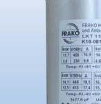
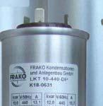
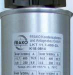
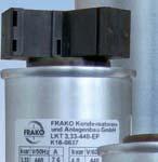
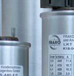

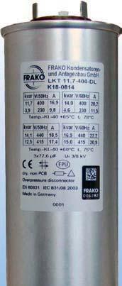
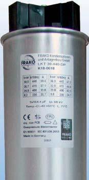
3 Power Factor Correction Capacitors Type LKT Features that matter: Overcurrent up to 2.2 times rated current Inrush current up to 300 times rated current Self-healing type, segmented film technology plus overpressure disconnector Environment-friendly, dry type CO 2 emission reduction Safes energy costs 3


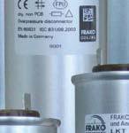
4 Power Factor Correction Capacitors Type LKT General Remarks FRAKO Power Factor Correction Capacitors are produced in unique advanced technology and incorporate a triple safety feature. FRAKO is the first capacitor manufacturer who succeeded to combine self-healing capacitor film with segmented film and overpressure disconnection. This manufacturing technique guarantees significantly improved operational reliability of capacitors on power factor correction. We reserve the right to make alterations which are based on newly acquired knowledge or which contribute to an improvement in our products. Technical Remarks For the operation of Power Factor Correction Capacitors three aspects are of utmost importance: High overload capacity Long life expectancy Safe reaction at overload Overload Capacity In networks where the pollution with harmonics is permanently increasing, surplus loads in capacitors have to be reckoned with. Apart from the higher voltage load it is especially the higher effective current during network resonances, that can considerably further stress the capacitors: Life Expectancy The use of thoroughly tested material as well as careful processing ensures quality and a long life expectancy of the products. FRAKO produces its capacitors according to own specifications, which surpass by far the requirements of EN /2. Quality tests following each single manufacturing step, verify an outstanding manufacturing quality. Combined with a unique capacitor manufacturing technology, FRAKO achieves a worldwide leading durability. For example, the consistently low power loss over many years is achieved by using a special mineral filler and stabilizer which can avoid permanent partial discharges within the dielectric. Vacuum drying and temperature storage over several days avoid oxygen inclusion, which would accelerate the aging process of a capacitor. This means an extra effort in our production which, however, pays-off with a longer life expectancy. Safety Features FRAKO Power Factor Correction Capacitors operate with triple safety: Self-healing at over-voltage Reliable in operation because of segmented film An overpressure disconnector disconnects the capacitors from the mains at the end of their lifetime or at dangerous overload. Capacitor current If, for example, the 11th harmonic is present with 8% of the rated network voltage, the r.m.s. value of the rated voltage is only increased by some 0.3%, but the current in the capacitors will exceed its rated value by 33%. It becomes clear that the ability of a capacitor to withstand excessive current is significantly greater than the ability to withstand excessive voltage. Therefore FRAKO designs its capacitors as follows: Max.overcurrent up to 2.2 times - for the Heavy Duty version: up to 2.7 times - rated current Max. inrush current up to 300 times - for the Heavy Duty version: up to 450 times - rated current Self-healing segmented capacitor film The principle of the overpressure disconnector Patent No
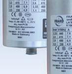
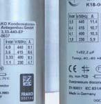
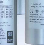
5 Power Factor Correction Capacitors Type LKT To verify the correct functioning of the integrated safety systems, FRAKO regularly draws sample capacitors from the production line. A constantly outstanding quality can be achieved and maintained only this way. Voltage Load Capacity FRAKO Power Factor Correction Capacitors have a load capacity in accordance with EN and -2 as well as IEC and -2: Rated voltage [V] 50 Hz Over-voltage [V] 8 hours daily min. daily min. daily min. daily Application FRAKO manufactures four series of Power Factor Correction Capacitors: Basic, Standard, Premium and NEW! Heavy Duty. We recommend Basic Capacitors for networks with low harmonic content and normal ambient temperature. Standard Capacitors are recommended for networks with higher harmonic levels and/or high ambient temperature. Premium Capacitors should be used for demanding networks (i.e. networks with very high harmonic levels ans/or very high ambient temperature). Heavy Duty Capacitors are recommended for extreme demanding network- and ambient conditions. All four series of capacitors are of excellent FRAKO quality. FRAKO holds the Management System Certificate ISO 9001 and the Environmental Management System ISO Mechanical Construction Cylindrical aluminium case with mounting stud M12 12, low loss self-healing dielectric made from segmented metallized polypropylene film. Filled with a PCB-free, flame inhibiting, mineral filler with adhesive stabilizer and integrated mechanical overpressure disconnector. Permanently connected external discharge resistors at the terminals. The connecting terminal, which is available as an accessory, protects against direct contact of the fast-on terminals and meets the protection class IP 20. Design FRAKO Power Factor Correction Capacitors are available as three-phase capacitors in four versions: Basic, Standard, Premium and NEW! Heavy Duty. The singlephase capacitors are available as Standard version. Rating kvar; V; 50 or 60 Hz (other Voltages on request!) Capacitance and Rating Tolerance ± 5% Power Loss Approx. 0.5 Watt / kvar measured at the connecting terminal (including discharge resistors). Aprox. 0.2 Watt / kvar dielectric power loss measured at the capacitor coils. Temperatur Class up to - 40 C; + 65 C depending on design Discharging According to EN 60831, every power capacitor must have a discharge device which guarantees a discharge to 75 V within three minutes. FRAKO capacitors have integrated discharge resistors which guarantee a discharge to 50 V within one minute. Accessories for FRAKO Power Factor Correction Capacitors All capacitors can be equipped with a patented connecting terminal in tension spring method against surcharge. This connecting terminal ensures a fast, perfect and permanent electrical contact of the connecting wires. All capacitors up to diameter 70 mm can be equipped with a plastic cap and rubber sleeve to cover the connections. Article-No. Description Type Plug-in type connecting AKD 25/3 terminal for capacitors with 60 and 70 mm, 3-phase Plug-in type connecting AKD 25/2 terminal for capacitors with 60 and 70 mm, singlephase Plug-in type connecting AKD 30/3 terminal for capacitors with 85 mm, 3-phase Plastic caps for LKT with LKT mm Plastic caps for LKT with LKT mm Rubber sleeve LKT 3
6 Power Factor Correction Capacitors Type LKT Technical Data Technical Data Basic Capacitor Standard Capacitor Premium Capacitor Heavy Duty Capacitor operated with DL-specification operated with DP-specification* Type LKT -DB LKT -DP/EP LKT -DL LKT -DL LKT -HD Rated reactive kvar kvar kvar kvar kvar power Rated voltage V V V V V Rated frequency 50/60 Hz 50/60 Hz 50/60 Hz 50/60 Hz 50/60 Hz Max. overcurrent (permanently) Max. inrush current 1.5 l N (at rated voltage, 50 Hz) 200 l N (at rated voltage, 50 Hz) 1.8 l N (at rated voltage, 50 Hz) 250 l N (at rated voltage, 50 Hz) Temperature class -25ºC / D -40 / +60ºC continuous Min. / max. temperature Max. case temperature Dielectric power loss Test voltage 2.15 U N for 2 s 2.15 U N for 2 s terminal / terminal 1.85 U N for 18 s 1.85 U N for 18 s Test voltage terminal / case 2.2 l N (at rated voltage, 50 Hz) 300 l N (at rated voltage, 50 Hz) -40 / +65ºC continuous 2.0 l N (at rated voltage, 50 Hz) 300 l N (at rated voltage, 50 Hz) -40 / +60ºC continuous 2.7 l N (at rated voltage, 50 Hz) 450 l N (at rated voltage, 50 Hz) -40 / +65ºC continuous -25ºC / +55ºC -40ºC / +60ºC -40ºC / +65ºC -40ºC / +60ºC -40ºC / +65ºC 70ºC 75ºC 78ºC 75ºC 78ºC 0.2 W/kvar 0.2 W/kvar 0.2 W/kvar 0.2 W/kvar 0.2 W/kvar 2.15 U N for 2 s 2.15 U N for 2 s 2.15 U N for 2 sec U N for 18 s 1.85 U N for 18 s 1.85 U N for 18 sec. 3,900 V, 2 s 3,900 V, 2 s 3,900 V, 2 s 3,900 V, 2 s 3,900 V, 2 s Isolation level 3/8 kv 3/8 kv 3/8 kv 3/8 kv 3/8 kv Mean life 100,000 h. 130,000 h. 170,000 h. 130,000 h. 200,000 h. expectancy Max. humidity 95% 95% 95% 95% 95% Max. altitude 4,000 m 4,000 m 4,000 m 4,000 m 4,000 m Number of 20,000 40,000 60,000 60, ,000 annual switching operations Discharging level 50 V 50 V 50 V 50 V 50 V in 60 s Recommended for Networks with low harmonic content and normal ambient temperature Networks with higher harmonic levels and/or high ambient temperature Networks with higher harmonic levels and/or high ambient temperature Demanding networks (i.e. networks with very high harmonic levels and/or very high ambient temperature) NEW NEW NEW NEW Extreme demanding network- and ambient conditions Generally, DL-type capacitors can also be operated at higher voltages with the DP-type specification. Please note that the DP values in the chart are marked with *. Temperature class admissible ambient temperature maximum mean over 24 h highest mean over 1 year D 55ºC 45ºC 35ºC 4
7 Power Factor Correction Capacitors Type LKT Dimensions 12 h h h h M M12 M12 M12 67 / 77 Capacitors with d = 60 / 70 mm for connection with flat cable plug mm Capacitors with d = 60 / 70 mm Spring tension terminal AKD 25/3 2 6 mm 2 Art.-No Capacitors with d = 85 mm for connection with flat cable plug mm Capacitors with d = 85 mm Spring tension terminal AKD 30/3 16 mm 2 Art.-No Plastic cap and rubber sleeve LKK 60/70 for capacitors with: d = 60 mm (Art.No ) / d = 70 mm (Art.No ) (not available for capacitors with d = 85 mm) rubber sleeve Art.-No
8 Power Factor Correction Capacitors Type LKT -DB for 50 Hz Basic Capacitors Capacitor Type Dimensions mm Article-No. Rated Reactive Power in kvar at Rated Voltage 50 Hz 230 V 250 V 300 V 400 V 415 V 440 V 460 V 480 V 525 V Three-phase capacitors LKT DB LKT DB LKT DB LKT DB LKT DB LKT DB LKT DB LKT DB LKT DB LKT DB LKT DB LKT DB LKT DB LKT DB LKT DB LKT DB LKT DB LKT DB LKT DB LKT DB LKT DB LKT DB
9 Power Factor Correction Capacitors Type LKT -DB for 60 Hz Basic Capacitors Capacitor Type Dimensions mm Article-No. Rated Reactive Power in kvar at Rated Voltage 60 Hz 230 V 250 V 300 V 400 V 415 V 440 V 460 V 480 V 525 V Three-phase capacitors LKT DB LKT DB LKT DB LKT DB LKT DB LKT DB LKT DB LKT DB LKT DB LKT DB LKT DB LKT DB LKT DB LKT DB LKT DB LKT DB LKT DB LKT DB LKT DB LKT DB LKT DB LKT DB
10 Power Factor Correction Capacitors Type LKT -DP for 50 Hz Standard Capacitors (three-phase) Capacitor Type Dimensions mm Article-No. Rated Reactive Power in kvar at Rated Voltage 50 Hz 230 V 250 V 300 V 400 V 415 V 440 V 460 V 480 V 525 V Three-phase capacitors LKT DP LKT DP LKT DP LKT DP LKT DP LKT DP LKT DP LKT DP LKT DP LKT DP LKT DP LKT DP LKT DP LKT DP LKT DP LKT DP LKT DP LKT DP LKT DP LKT DP LKT DP LKT DP LKT DP LKT DP LKT DP
11 Power Factor Correction Capacitors Type LKT -DP for 60 Hz Standard Capacitors (three-phase) Capacitor Type Dimensions mm Article-No. Rated Reactive Power in kvar at Rated Voltage 60 Hz 230 V 250 V 300 V 400 V 415 V 440 V 460 V 480 V 525 V Three-phase capacitors LKT DP LKT DP LKT DP LKT DP LKT DP LKT DP LKT DP LKT DP LKT DP LKT DP LKT DP LKT DP LKT DP LKT DP LKT DP LKT DP LKT DP LKT DP LKT DP LKT DP LKT DP LKT DP LKT DP LKT DP LKT DP
12 Power Factor Correction Capacitors Type LKT -DP for 50 Hz and 60 Hz Standard Capacitors (three-phase) Capacitor Type Dimensions mm Article-No. Rated Reactive Power in kvar at Rated Voltage 50 Hz 525 V 570 V 600 V 615 V 690 V 750 V 760 V 800 V Three-phase capacitors LKT DP LKT DP LKT DP LKT DP LKT DP LKT DP LKT DP LKT DP LKT DP LKT DP LKT DP LKT DP Capacitor Type Dimensions mm Article-No. Rated Reactive Power in kvar at Rated Voltage 60 Hz 525 V 570 V 600 V 615 V 690 V 750 V 760 V 800 V Three-phase capacitors LKT DP LKT DP LKT DP LKT DP LKT DP LKT DP LKT DP LKT DP LKT DP LKT DP LKT DP LKT DP
13 Power Factor Correction Capacitors Type LKT -EP for 50 Hz and 60 Hz Standard Capacitors (single-phase) Capacitor Type Dimensions mm Article-No. Rated Reactive Power in kvar at Rated Voltage 50 Hz 230 V 250 V 300 V 400 V 415 V 440 V 460 V 480 V 525 V Single-phase capacitors LKT EP LKT EP LKT EP LKT EP LKT EP LKT EP LKT EP LKT EP LKT EP LKT EP LKT EP LKT EP Capacitor Type Dimensions mm Article-No. Rated Reactive Power in kvar at Rated Voltage 60 Hz 230 V 250 V 300 V 400 V 415 V 440 V 460 V 480 V 525 V Single-phase capacitors LKT EP LKT EP LKT EP LKT EP LKT EP LKT EP LKT EP LKT EP LKT EP LKT EP LKT EP LKT EP
14 Power Factor Correction Capacitors Type LKT -DL for 50 Hz Premium Capacitors Capacitor Type Dimensions mm Article- No. Rated Reactive Power in kvar at Rated Voltage 50 Hz 230 V 250 V 300 V 400 V 415 V 440 V 460 V 480 V 525 V 570 V 615 V Three-phase capacitors LKT DL * 6.1* LKT DL * 7.6* LKT DL * 11.3* LKT DL * 12.1* LKT DL * 14.2* LKT DL * 15.1* LKT DL * 24.2* LKT DL * 6.0* LKT DL * 9.0* LKT DL * 10.8* LKT DL * 14.4* LKT DL * 21.0* LKT DL * LKT DL * LKT DL * LKT DL * LKT DL * LKT DL * LKT DL * LKT DL * 5.7* LKT DL * 8.1* LKT DL * 10.6* LKT DL * 11.4* Generally, DL-type capacitors can also be operated at higher voltages with the DP-type specification. Please note that the DP values in the chart are marked with *. 12
15 Power Factor Correction Capacitors Type LKT -DL for 60 Hz Premium Capacitors Capacitor Type Dimensions mm Article- No. Rated Reactive Power in kvar at Rated Voltage 60 Hz 230 V 250 V 300 V 400 V 415 V 440 V 460 V 480 V 525 V 570 V 615 V Three-phase capacitors LKT DL * 7.3* LKT DL * 9.1* LKT DL * 13.5* LKT DL * 14.5* LKT DL * 17.0* LKT DL * 18.2* LKT DL * 29.0* LKT DL * 7.1* LKT DL * 10.9* LKT DL * 13.0* LKT DL * 17.3* LKT DL * 25.1* LKT DL * LKT DL * LKT DL * LKT DL * LKT DL * LKT DL * LKT DL * LKT DL * 6.9* LKT DL * 9.7* LKT DL * 12.7* LKT DL * 13.7* Generally, DL-type capacitors can also be operated at higher voltages with the DP-type specification. Please note that the DP values in the chart are marked with *. 13
16 Power Factor Correction Capacitors Type LKT -HD for 50 Hz and 60 Hz Heavy Duty Capacitors Capacitor Type Dimensions mm Article-No. Rated Reactive Power in kvar at Rated Voltage 50 Hz 230 V 250 V 300 V 400 V 415 V 440 V 460 V 480 V 500 V 525 V Three-phase capacitors LKT HD LKT HD LKT HD LKT HD LKT HD LKT HD Capacitor Type Dimensions mm Article-No. Rated Reactive Power in kvar at Rated Voltage 60 Hz 230 V 250 V 300 V 400 V 415 V 440 V 460 V 480 V 500 V 525 V Three-phase capacitors LKT HD LKT HD LKT HD LKT HD LKT HD LKT HD Heavy Duty Capacitors NEW Overcurrent up to 2.7 times rated current Inrush current up to 450 times rated current Mean Life expectancy: 200,000 h. Up to 100,000 annual switching operations 14


17 Basic Harmonic Filter Reactors Type FDK Features that matter: Low losses Complete with mounting brackets and connecting clamps Temperature range up to +60 C Temperature switches available as option 11
18 Basic Harmonic Filter Reactors Type FDK Application Used in conjunction with LKT type power capacitors, har- power factor correction systems. This enables users installing distribution boards to construct customized systems themselves. Design Low-loss, three-phase assembly complete with mounting brackets. Series Resonance Frequency Version Series Detuning For networks with resonance factor utility company AF frequency remote control 1) P7 189 Hz p=7% > 228 Hz Please refer also to the design notes given in our Manual of Power Factor Correction. (other series resonance frequencies on request) 1) Mounting The reactor must be mounted in a suitable enclosure range. Connections The coil line-side (U, V, W) and load-side (X, Y, Z) can be connected to the switchgear directly or via terminals. Standards IEC 60289, IEC 60076, VDE 0532 Applicable Standards When installing and connecting power capacitors in Germany, the standards VDE 0100 IEC 60364, VDE 0105 IEC 60050, IEC 60529, VDE 0560 Part 46 IEC and VDE 0106 Part 100 must be complied with. In other countries the equivalent local regulations must be observed. Technical Data Tolerance of inductance: +/- 5 % Max. ambient temperature: + 60 C Temperature class: H 180 C Insulation level: 3 kvac Winding material: Al Color: red or light brown Option Temperature switch 130 C +/- 5 C, Voltage 250 VAC (type FDKT) Mechanical Data Connection diagram U X V Y W Z Available Types We reserve the right to make changes to the dimensions and design of the products in this data sheet. 12


19 Standard Harmonic Filter Reactors Type FDR/FKD Features that matter: Low losses Complete with mounting brackets and connecting cables Including temperature switches Temperature range up to +60 C 13
20 Harmonic Filter Reactors Type FDR / FKD Application Used in conjunction with LKT type Power Factor Cor- reactors) make it possible to install detuned versions of tems. This enables users installing distribution boards to construct customized systems themselves. Design Low-loss, three-phase assembly complete with mounting brackets, connecting cables and thermal trip. Series Resonance Frequency Version Series Detuning For networks with resonance factor utility company AF frequency remote control 1) P1 134 Hz p=14 % > 166 Hz P7 189 Hz p= 7 % > 228 Hz 1) Please refer also to the design notes given in our Manual of Power Factor Correction. (other series resonance frequencies on request) Mounting The reactor must be mounted in a suitable enclosure range. Connections The coil line-side (U1, V1, W1) and load-side (U2, V2, W2) cables can be connected to the switchgear directly or via terminals. The temperature switch (contacts open at 140 C) must be connected to a trip/alarm circuit in the control system. Applicable Standards When installing and connecting power capacitors in Germany, the standards VDE 0100 IEC 60364, VDE 0105 IEC 60050, IEC 60529, VDE 0560 part 46 IEC and VDE 0106 part 100 must be complied with. In other countries the equivalent local regulations must be observed. Load Capacity Version Power loss Permissible harmonic voltage W/kvar 250 Hz 350 Hz P % 6% P % 6% Power Loss W / kvar (depending on version and level of harmonics) Temperature Range 10 to +60 C Ingress Protection IP00 to IEC for mounting within an enclosure Important Note Please use only the correct number of the appropriate power capacitors as stated in the table for each individual to, the resulting series resonance frequency can under certain circumstances move into a critical range. Apart from possibly overloading the installed components, the utility company s remote control systems could also be adversely affected. Technical Data Specimen order 1 P.F. correction stage with 7 % detuning factor 25kvar at 400V/50Hz supply voltage 2 power capacitors Type LKT DL Art.-No terminal blocks Type AKD 25/3 Art.-No Type FDR P7 Art.-No Specimen order 2 P.F. correction stage with 14% detuning factor 12.5kvar at 400V/50Hz supply voltage 1 power capacitor Type LKT DP Art.-No terminal block Type AKD 25/3 Art.-No Type FKD P1 Art.-No Specimen order 3 P.F. correction stage with 14 % detuning factor 20 kvar at 400 V/50 Hz supply voltage 1 power capacitor Type LKT DL Art.-No power capacitor Type LKT DP Art.-No terminal blocks Type AKD 25/3 Art.-No Type FKD P1 Art.-No
21 Harmonic Filter Reactors Type FDR / FKD Capacitors and Harmonic Filter Reactors for 230 V/50 Hz mains network Resonance frequency fres: 189 Hz, detuning factor p= 7% Type and Quantity of the required capacitors Rated power of Capacitor Reactor combination Rated current of Capacitor Reactor combination LKT DP Art.-No LKT DP Art.-No LKT DP Art.-No LKT DP Art.-No Dimensions in mm Weight Harmonic Filter Reactors Q LC [kvar] In [A] W W1 H D D1 kg Art.-No. Type FDR P FKD P FDR P FKD P FKD P FDR P FKD P7 Capacitors and Harmonic Filter Reactors for 230 V/60 Hz mains network Resonance frequency fres: 227 Hz, detuning factor p= 7% Type and Quantity of the required capacitors Rated power of Capacitor Reactor combination Rated current of Capacitor Reactor combination LKT DP Art.-No LKT DP Art.-No Dimensions in mm Weight Harmonic Filter Reactors Q LC [kvar] In [A] W W1 H D D1 kg Art.-No. Type FKD Hz-P FDR Hz-P7 FDR / FKD dimensions 15
22 Harmonic Filter Reactors Type FDR / FKD Capacitors and Harmonic Filter Reactors for 400 V/50 Hz mains network Resonance frequency fres: 189 Hz, detuning factor p= 7% Type and Quantity of the required capacitors Rated power of Capacitor Reactor combination Rated current of Capacitor Reactor combination LKT DL Art.-No LKT DL Art.-No LKT 12,5-440-DP Art.-No LKT DL Art.-No LKT DP Art.-No Dimensions in mm Weight Harmonic Filter Reactors Q LC [kvar] In [A] W W1 H D D1 kg Art.-No. Type FKD P FKD P FKD P FDR P FKD P FKD P FDR P FKD P FDR P FDR P7 Resonance frequency fres: 134 Hz, detuning factor p= 14% Type and Quantity of the required capacitors Rated power of Capacitor Reactor combination Rated current of Capacitor Reactor combination LKT DL Art.-No LKT DL Art.-No LKT DL Art.-No LKT DP Art.-No LKT DL Art.-No LKT DL Art.-No Dimensions in mm Weight Harmonic Filter Reactors Q LC W W1 H D D1 kg Art.-No. Type [kvar] In [A] FKD P FKD P FKD P FKD P FKD P FDR P FDR P1 16
23 Harmonic Filter Reactors Type FDR / FKD Capacitors and Harmonic Filter Reactors for 415 V/50 Hz mains network Resonance frequency fres: 189 Hz, detuning factor p= 7% Type and Quantity of the required capacitors Rated power of Capacitor Reactor combination Rated current of Capacitor Reactor combination LKT DP Art.-No LKT DP Art.-No Dimensions in mm Weight Harmonic Filter Reactors Q LC [kvar] In [A] W W1 H D D1 kg Art.-No. Type FDR P FDR P FDR P FDR P FDR P7 Capacitors and Harmonic Filter Reactors for 440 V/50 Hz mains network Resonance frequency fres: 189 Hz, detuning factor p= 7% Type and Quantity of the required capacitors Rated power of Capacitor Reactor combination Rated current of Capacitor Reactor combination LKT DL Art.-No Dimensions in mm Weight Harmonic Filter Reactors Q LC [kvar] In [A] W W1 H D D1 kg Art.-No. Type FKD P FKD P7 17
24 Harmonic Filter Reactors Type FDR / FKD Capacitors and Harmonic Filter Reactors for 440 V/60 Hz mains network Resonance frequency fres: 227Hz, detuning factor p= 7% Type and Quantity of the required capacitors Rated power of Capacitor Reactor combination Rated current of Capacitor Reactor combination LKT DL Art.-No LKT DP Art.-No LKT DL Art.-No LKT DL Art.-No LKT DL Art.-No LKT DL Art.-No Dimensions in mm Weight Harmonic Filter Reactors Q LC [kvar] In [A] W W1 H D D1 kg Art.-No. Type FKD Hz-P FKD Hz-P FKD Hz-P FKD Hz-P FKD Hz-P FDR Hz-P7 Capacitors and Harmonic Filter Reactors for 460 V/60 Hz mains network Resonance frequency fres: 227 Hz, detuning factor p= 7% Type and Quantity of the required capacitors Rated power of Capacitor Reactor combination Rated current of Capacitor Reactor combination LKT DP Art.-No Dimensions in mm Weight Harmonic Filter Reactors Q LC [kvar] In [A] W W1 H D D1 kg Art.-No. Type FDR Hz-P FDR Hz-P FDR Hz-P7 18
25 Harmonic Filter Reactors Type FDR / FKD Capacitors and Harmonic Filter Reactors for 480 V/60 Hz mains network Resonance frequency fres: 227 Hz, detuning factor p= 7% Type and Quantity of the required capacitors Rated power of Capacitor Reactor combination Rated current of Capacitor Reactor combination LKT DP Art.-No LKT DL Art.-No LKT DL Art.-No LKT DL Art.-No Dimensions in mm Weight Harmonic Filter Reactors Q LC [kvar] In [A] W W1 H D D1 kg Art.-No. Type FKD Hz-P FKD Hz-P FDR Hz-P7 Capacitors and Harmonic Filter Reactors for 525 V/50 Hz mains network Resonance frequency fres: 189 Hz, detuning factor p= 7% Type and Quantity of the required capacitors Rated power of Capacitor Reactor combination Rated current of Capacitor Reactor combination LKT DL Art.-No LKT DL Art.-No LKT DL Art.-No LKT DL Art.-No Dimensions in mm Weight Harmonic Filter Reactors Q LC [kvar] In [A] W W1 H D D1 kg Art.-No. Type FKD P FKD P FKD P FDR P FKD P FDR P7 Resonance frequency fres: 134 Hz, detuning factor p= 14% Type and Quantity of the required capacitors Rated power of Capacitor Reactor combination Rated current of Capacitor Reactor combination LKT DL Art.-No LKT DL Art.-No Dimensions in mm Weight Harmonic Filter Reactors Q LC [kvar] In [A] W W1 H D D1 kg Art.-No. Type FDR P FDR P1 19
26 Harmonic Filter Reactors Type FDR / FKD Capacitors and Harmonic Filter Reactors for 690 V/50 Hz mains network Resonance frequency fres: 189 Hz, detuning factor p= 7% Type and Quantity of the required capacitors Rated power of Capacitor Reactor combination Rated current of Capacitor Reactor combination LKT EP Art.-No Dimensions in mm Weight Harmonic Filter Reactors Q LC [kvar] In [A] W W1 H D D1 kg Art.-No. Type FDR P FDR P7 Resonance frequency fres: 134 Hz, detuning factor p= 14% Type and Quantity of the required capacitors Rated power of Capacitor Reactor combination Rated current of Capacitor Reactor combination LKT EP Art.-No LKT EP Art.-No LKT EP Art.-No Dimensions in mm Weight Harmonic Filter Reactors Q LC [kvar] In [A] W W1 H D D1 kg Art.-No. Type FKD P FKD P1 20


27 Capacitor Switching Contactors Type K3...-A, K3...-K Features that matter: Patented design with significant damping on inrush-current Long-life contactors tested by FRAKO up to 100,000 switching operations Suitable for unchoked and choked Power Factor Correction Systems Very high operational reliability 21

28 Capacitor Switching Contactors for unchoked and choked PFC Systems Description Capacitor contactors for unchoked power factor correction systems During the switching of unchoked power factor correction capacitors a peak-switching current of 200 times of the nominal current can occur. This load is stressing the capacitors and the switching contacts of the contactors immensely. This can lead to welded main contacts of contactors. Therefore modern power factor correction systems are currently equipped with special capacitor contactors additionally with resistance wires. The in-rush current will be damped strongly by the resistors. After approximately 5 ms the main contacts of the contactor are switching in and taking over the current supply to the capacitors. Further to this the leading contacts open up and no cur- to avoid an additional power loss. Capacitor contactors with leading transition contact and additional resistance wires offer the following advantages to power factor correction system applications: Improvement of the voltage quality during the switching process Long life of the contactors High operational reliability of the power factor correction system Extension of the maintenance periods of the power factor correction systems Suitable for choked and unchoked power factor correction systems due to leading transition contacts opening during permanent operation. Capacitor contactors for choked power factor correction systems When choked power factor correction systems are switched, the peak-switching current is essentially lower because of the high inductivity of the harmonic systems. By using special wear-resistant contact material for these applications it is possible to use capacitor contactors without series resistors. These special capacitor contactors offer the following advantages for choked power factor correction systems: Safe switching on and off of choked capacitor steps Improved voltage quality through chatter-proofed switching operations Long-life of the contactors (> 100,000 switching operations) High operational reliability of the power factor correction system 22
29 Capacitor Switching Contactors for unchoked and choked PFC Systems Technical Data Rated operational power at 50/60 Hz Aux. contacts Type Article-No. Weight Ambient temperature: built-in add. 50 C 60 C Coil voltage 380 V 415 V 660 V 380 V 415 V 660 V V 50 Hz 400 V 440 V 690 V 400 V 440 V 690 V kvar kvar kvar kvar kvar kvar NO NC pcs. kg/pc ) K3-18K ) K3-24K ) K3-32K ) K3-50K ) K3-62K ) ) ) ) K3-74K ) K3-90K ) ) ) ) ) ) 6 4) K3-115K ) 2) 3) 1HN.. or HA.. snap-on 2HB.. for side mounting and 1HN.. or HA.. snap-on Consider the max. thermal current of the contactor K3-74 A: 4) 5) 2HB.. on the left or right side and 4 HN.. or HA.. snap-on Consider the min. cross-section of conductor at max. load I th 130 A e. Operating Conditions: Capacitor switching contactors are protected against contact welding for a prospective making current of 200 x l e. Technical Data acc. to IEC , IEC , EN , EN , VDE 0660 Type K3-18K K3-24K K3-32K K3-50K K3-62K K3-74K K3-90K K3-115K Max. frequency of operations z 1/h Contact life: unchoked capacitor banks S x Contact life: choked banks S x Rated operational current l e at 50 C A at 60 C A Fuses gl (gg) from/to A 35/63 50/80 63/100 80/ / / / /250 L1 L2 L3 Mounting Instructions used only, because abnormal temperatures within the area of the resistor spirals cannot be excluded. Typical Circuit Diagram A1 A Auxiliary Contact Blocks Rated operational current Contacts Type Article-No. Weight AC15 AC1 230 V 400 V 690 V A A A For contactors NO NC kg/pc K3-24 to K HB for side mounting K3-18 to K HN
30 Capacitor Switching Contactors for unchoked and choked PFC Systems Technical Data Rated operational power at 50/60 Hz Aux. contacts Type Article-No. Weight Ambient temperature: built-in add. 50 C 60 C Coil voltage 380 V 415 V 660 V 380 V 415 V 660 V V 50 Hz 400 V 440 V 690 V 400 V 440 V 690 V _ kg/pc. kvar kvar kvar kvar kvar kvar NO NC pcs ) K3-18A ) K3-24A ) K3-32A ) K3-50A ) K3-62A ) 75 3) ) K3-74A ) K3-90A ) 103 5) 148 5) 90 5 ) 93 5) 148 5) 9 4) K3-115A ) 4HN.. or HA.. snap-on 2) 2HB11 on the left or right side and 4HN.. or HA.. snap-on 3) Consider the max. thermal current: I 130 A 4) 2HB.. on the left or right side and 7 HN.. or HA.. snap-on 5) Consider the min. cross-section of conductor at max. load th L1 L2 L3 Mounting Instructions Typical Circuit Diagram A1 A used only, because abnormal temperatures within the area of the resistor spirals cannot be excluded. Dimensions Capacitor switching contactors, AC-operated K3-18K Contactors, AC-operated K3-18A ø5 M ø5 M3.5 K3-24K00 K3-32K K3-24A00 K3-32A ø4.5 ø M5 115 M
31 Capacitor Switching Contactors for unchoked and choked PFC Systems Dimensions Capacitor switching contactors, AC-operated K3-50K00 K3-62K00 K3-74K Contactors, AC-operated K3-50A00 K3-62A00 K3-74A ø5.5 ø M6 M K3-90K00 K3-115K K3-90A00 K3-115A Ø6 Ø6 Ø6 Ø M8 M Technical Data Main Contacts Type K3-18K K3-24K K3-32K K3-50K K3-62K K3-74K K3-90K K3-115K Switching of three-phase current pfc-systems Rated operational current l e 690 V A ) ) Rated operational power V kvar ) V kvar ) ) V kvar ) ) 500 V kvar ) 525 V kvar ) V kvar ) 1000 V kvar ) Rated operational current l e 690 V A ) Rated operational power V kvar ) V kvar ) V kvar ) 500 V kvar ) 525 V kvar ) V kvar ) 1000 V kvar ) 1) Consider the max. thermal current: I th 130 A 2) Consider the min. cross-section of conductor at max. load 25
32 Capacitor Switching Contactors Data according to IEC , EN , VDE0660 Technical Data Main Contacts Type K3-18A K3-24A K3-32A K3-50A K3-62A K3-74A K3-90A K3-115A Switching of three-phase current pfc-systems Rated operational current l e 690 V A ) ) Rated operational power V kvar ) V kvar ) ) V kvar ) ) 500 V kvar ) 525 V kvar ) V kvar ) 1000 V kvar ) Rated operational current l e 690 V A ) Rated operational power V kvar ) V kvar ) V kvar ) 500 V kvar ) 525 V kvar ) V kvar ) 1000 V kvar ) 1) Consider the max. thermal current: I th 130 A 2) Consider the min. cross-section of conductor at max. load Main Contacts Type K3-18 K3-24 K3-32 K3-50 K3-62 K3-74 K3-90 K3-115 Maximum ambient temperature Operation open C 40 to +60 (+90) 1) enclosed C 40 to +40 Storage C 50 to +90 Short circuit protection for contactors without thermal overload relay Coordination-type 1 according to IEC Contact welding without Hazard of persons Max. fuse size gl (gg) A Mechanical life AC-operated S x DC-operated S x Short time current 10s-current A Power loss per pole At l e /AC3 400 V W ) With reduced control voltage range 0.9 up to 1.0 x U s and with reduced rated current I e /AC1 according to I e /AC3 26


33 Discharge Reactors Type FR 3AC Features that matter: One type for every application in Power Factor Correction Systems Low operating losses Ambient temperature up to +60 C Allows very fast re-switching of the same capacitor step 27
34 Discharge Reactors Type FR 3AC Description Discharge reactors have lower losses than discharging resistors. This could be an important fact in modern power factor correction systems if ambient temperature is a topic to solve. The high AC resistance of the discharge reactors generates very small losses, also when capacitors were permanently connected to the network. In the moment when capacitors are switched off, the low DC resistance of the discharge reactor is responsible for a very fast discharging time of the capacitors. It will only take a few seconds. This fast discharging also allows a very fast re-switching of the same capacitor. Technical Data Discharge reactor, type: FR3AC V Article-No Ordering code Rated operating voltage: 3AC 230 V 690 V Frequency: Hz Inductance: 70 H Permissible discharges: 3 / min Temperature class: T40 / E Ambient temperature: C Protection class: IP 00 Abutting cross section: 0.75 mm mm 2 Fixing torque: 0.5 Nm Total weight: 0.5 kg Testing voltage: 4 kvac Standards: EN Dimensions in mm: WxHxD 77 x 96 x 55 28


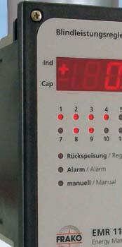
35 Power Factor Control Relays Type EMR1100 / EMR1100S / RM9606 / RM2106 / RM2112 Features that matter: Fully automatic and simple commissioning Patented control characteristic no overcompensation during low load Measurement and monitoring of harmonics Overcurrent trip function protection for capacitors Four-quadrant regulation 29
, phase angle, connected capacitor stages and switching sequences. Operator Overview Through clear digital display of key momentary values and operating parameters.")
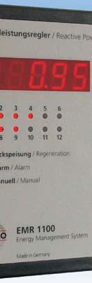
36 Power Factor Control Relays Type EMR 1100S / EMR 1100 Description Microprocessor-based control relay for intelligent control of capacitor banks with 12 control contacts. Simple Commissioning value), phase angle, connected capacitor stages and switching sequences. Operator Overview Through clear digital display of key momentary values and operating parameters. Power factor (cos ) Apparent (RMS), active and reactive currents 5th, 7th, 11th and 13th voltage harmonics Total capacitive power required to meet target power factor setting Monitoring of Harmonic Levels By continuous monitoring and display of harmonic voltage levels. In the event of harmonic levels exceeding programmable limits, all capacitors will be switched off through overcurrent alarm. Prolongs Switchgear Life The EMR 1100 counts, stores and displays the number of switching operations for each individual capacitor stage. An alarm is triggered if the switching counters exceed programmable limits. Additional Protection for Capacitors The RMS current monitoring function provides excellent especially when resonance causes an increase in harmonic levels. Intelligent Control for Increased Equipment Life Cyclic switching for capacitor stages of the same rating. Accurate switching of capacitor stages prevents unnecessary switchings for responsive control. Continuous optimisation of switching delay according to required reactive current. Features Potential-free alarm contact. Programmable overcurrent alarm threshold limit (from 1.05 to 3.0xI rms ). Continuous monitoring for defective capacitor stages through self adjustment of control program. Zero voltage and zero current tripping with alarm signal. Patented kinked control curve characteristics avoid overcompensation under light load. Four-quadrant power control with LED display when active power is generated into mains. Manual/automatic operation with ability to switch each individual capacitor stage ON or OFF. Target power factor setting adjustable from 0.80 inductive to 0.90 capacitive in steps of be excluded from normal automatic operation. Independent setting of capacitor switching time to match discharge time of capacitor stages. Suitable for current transformers with rated secondary current of 1 A or 5 A. Alarm Signals for Undercompensation High harmonic levels Overcurrent Switching counters Fault in voltage circuit (U = 0 alarm) Fault in current circuit (I = 0 alarm) Fault in capacitor stages (C = 0 alarm) Optional extension of the EMR 1100S to EMR 1100 full version by means of software upgrading Potential-free tariff switching contact to select two independent target power factor settings. Remote indication of the measuring values and historical data (daily curves, monthly and annual evaluation). Communication with Building control systems. measuring values with software EMR-SW via the RS232 interface. 30
, phase angle, connected capacitor stages and switching sequences. Operator Overview Through clear digital display of key momentary values and operating parameters.")

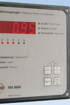
37 Power Factor Control Relays Type RM 9606 Description Microprocessor-based control relay for intelligent control of capacitor banks with 6 control contacts. Simple Commissioning value), phase angle, connected capacitor stages and switching sequences. Operator Overview Through clear digital display of key momentary values and operating parameters. Power factor (cos ) Apparent (RMS), active and reactive currents 5th, 7th, 11th and 13th voltage harmonics Total capacitive power required to meet target power factor setting Monitoring of Harmonic Levels By continuous monitoring and display of harmonic voltage levels. In the event of harmonic levels exceeding programmable limits, all capacitors will be switched off through overcurrent alarm. Prolongs Switchgear Life The RM 9606 counts, stores and displays the number of switching operations for each individual capacitor stage. An alarm is triggered if the switching counters exceed programmable limits. Additional Protection for Capacitors The RMS current monitoring function provides excellent especially when resonance causes an increase in harmonic levels. Intelligent Control for Increased Equipment Life Cyclic switching for capacitor stages of the same rating. Accurate switching of capacitor stages prevents unnecessary switchings for responsive control. Continuous optimisation of switching delay according to required reactive current. Features Potential-free alarm contact. Programmable overcurrent alarm threshold limit (from 1.05 to 3.0xI rms ). Continuous monitoring for defective capacitor stages through self adjustment of control program. Zero voltage and zero current tripping with alarm signal. Patented kinked control curve characteristics avoid overcompensation under light load. Four-quadrant power control with LED display when active power is generated into mains. Manual/automatic operation with ability to switch each individual capacitor stage ON or OFF. Target power factor setting adjustable from 0.80 inductive to 0.90 capacitive in steps of be excluded from normal automatic operation. Independent setting of capacitor switching time to match discharge time of capacitor stages. Suitable for current transformers with rated secondary current of 1 A or 5 A. Alarm Signals for Undercompensation High harmonic levels Overcurrent Switching counters Fault in voltage circuit (U = 0 alarm) Fault in current circuit (I = 0 alarm) Fault in capacitor stages (C = 0 alarm) via RS232 interface with EMR
38 Power Factor Control Relays Type RM 2106 / RM 2112 Description Microprocessor-based control relay for intelligent control of capacitor banks with 6 or 12 control contacts. Simple Commissioning value), phase angle, connected capacitor stages and switching sequences. Operator Overview Through clear digital display of key momentary values and operating parameters. Power factor (cos ) Total harmonic voltage distortion factor (% THVD) Number of active capacitor steps Extensive Analysis Record When in automatic mode, display of: Connection faults Capacity step faults Recognized step sequence Protection for Capacitors The optional RMS current monitoring function provides excellent protection for capacitor banks without harmonic in harmonic levels. The threshold can be set between 1.05 to 1.95 x I rms. Intelligent Control for Increased Equipment Life Cyclic switching for capacitor stages of the same rating. Accurate switching of capacitor stages prevents unnecessary switchings for responsive control. Continuous optimisation of switching delay according to required reactive current. Features Potential-free alarm contact. Programmable overcurrent alarm threshold limit. Continuous monitoring for defective capacitor stages through self adjustment of control program. Zero voltage and zero current tripping with alarm signal. Two control curves characteristics: to avoid overcompensation under light load. to avoid inductive reactive power under regeneration conditions. Four-quadrant power control with LED display when active power is generated into mains. Manual/automatic operation with ability to switch each individual capacitor stage ON or OFF. Target power factor setting adjustable from 0.85 inductive to 1.00 capacitive. Independent setting of capacitor switching time to match discharge time of capacitor stages. Suitable for current transformers with rated secondary current of 1 A or 5 A. Protection class terminals IP 20, housing IP 54 (when sealing ring is used). Alarm Signals for Overcurrent Fault in voltage circuit (U = 0 alarm) Fault in capacitor stages Article-No. Power Factor Control Relay Type With 6 control contacts RM With 12 control contacts RM With 6 control contacts RM With 12 control contacts EMR 1100 S With 12 control contacts and bus EMR 1100 interface to FRAKO Energy- Management-System Software-Upgrade EMR 1100 S EMR-Upgrade to full version EMR EMR-Software for EMR 1100 for EMR-Sofware Protection kit for protection class IP 54 32


39 Modular Construction System MCS System These components fit together Design your own high quality Power Factor Correction System Type-tested components High operational reliability of Power Factor Correction Systems Gain from 80 years experience in Power Factor Correction technologies 33
40 Modular Construction System MCS System Description The FRAKO MCS System is a modular system, with which a skilled switchgear manufacturer can design a technically high-quality power factor correction system. However, knowing our manual of power factor correction is absolutely important to design such a power the necessary planning information as well as all the important technical data. You can download the manual free of charge from our website or order it free of charge from your local FRAKO partner. The FRAKO MCS System consists of selected and tested components for the design of power factor correction systems. FRAKO uses these components in its own production of power factor correction systems in Teningen. This way the skilled switchgear manufacturer can gain from an experience and application know-how of almost 80 years. The FRAKO MCS System contains the following components: Power factor control relay Control terminal strip for power factor control relay and Power Factor Correction Systems Control wires Busbar holders NH-fuse base and NH-isolating switch NH-fuse links Contactors Discharge reactors Power factor correction capacitors Thyristor switches (see page 52) Page 37 Specimen order 1 shows the combination of all FRAKO components for a power factor correction power of 350 kvar at 400 V, 50 Hz and a step rating of 25kvar at a switching sequence of the capacitor steps of: 1:1:2:2:2:2:2:2. Page 38 Specimen order 2 shows the combination of all FRAKO components for a choked power factor correction system with a total power of 375 kvar at 400 V, 50Hz, a series resonance frequency of 189Hz (p=7%) and a step rating of 25 kvar at a switching sequence of the capacitor steps of: 1:2:2:2:2:2:2:2. 34
41 Modular Construction System MCS System Technical Data Power Factor Control Relays and accessories For technical details on our power factor control relays we would like to refer you to our catalogue (page 29 to 32). For the relays, FRAKO recommend to use the suitable control terminal strips, the thermal trip contact for the monitoring of the cabinet temperature as well as the prepared control cables. All items can be ordered as single components or as a complete control relay package. The following chart shows the different types of relays as well as the suitable accessories for the assembly and the connection of the devices. Article number: Description: Order Code: Power factor control relay with 6 control contacts RM with 6 control contacts RM with 12 control contacts RM with 12 control contacts EMR 1100 S with 12 control contacts and bus interface to FRAKO Energy-Management-System EMR Software-Upgrade EMR 1100 S to full version EMR 1100 Control terminal strip with thermal trip contact, pre-mounted suitable for RM 9606 RKL RM suitable for EMR 1100 / EMR 1100 S RKL EMR for extension units (only 12 control contacts) RKL Z cabinet Control cable, prepared for connection of RM 9606 with control terminal strip (length: 1000 mm, 6 control contacts) RK RM for connection of RM 9606 with control terminal strip (length: 1500 mm, 6 control contacts) RK RM for connection of EMR 1100 / EMR 1100 S with control terminal strip (length: 1150 mm, 12 control contacts) RK EMR for connection of EMR 1100 / EMR 1100 S with control terminal strip (length: 1500 mm, 12 control contacts) RK EMR for connection of the basic unit with the extension unit (length: 6 m, 12 control contacts) SS Reactive power factor control relay package Completely assembled and tested units comprising: Power factor control relay with control terminal strip, thermal trip contact and relay cable, length: 1150 mm RM 9606, control terminal strip with thermal trip contact, cable length: 1150 mm STR RM EMR 1100 S, control terminal strip with thermal trip contact, cable length: 1150 mm STR EMR 1100 S EMR 1100, control terminal strip with thermal trip contact, cable length: 1150 mm STR EMR 1100 RKL-EMR 1100 RKL-RM


42 Modular Construction System MCS System Technical Data Copper busbar holders, NH-fuses For the design of power factor correction systems FRAKO recommend to use the below-mentioned devices and fuses. The busbar holders have a centre to centre distance of 60 mm to the single copper busbars. The copper busbars have either dimensions of 30 5 mm or mm, depending on the total power of the power factor correction system. Article-No. Description Busbar holder with a bar centre to centre distance of 60 mm, Cu 30x10mm voltage of 690 VAC, can be used. These NH-fuse holders are also available as bus-mounting fuse holders for direct mounting on a busbar system with a bar centre to centre distance of 60 mm, or for mounting on mounting plates. Article-No. Description NH-bus-mounting fuse base size 00, 160 A, 690 VAC NH-bus-mounting fuse base size 00, 160 A, 690 VAC NH-fuse base for plate mounting size 00, 160 A, 690 VAC NH-fuse base for plate mounting size 00, 160 A, 690 VAC Cover for NH-fuses with nonisolated grip lugs NH-isolating switch size 00. Applicable up to a mains rated voltage of 690 VAC. Available as NH-bus-mounting isolating switches for direct mounting on a busbar system with 60 mm bar centre to centre distance, or for mounting on mounting plates. Article-No. Description NH-isolating switch for plate mounting size 00, 160 A, 690 VAC NH-isolating switch for plate mounting size 00, 160 A, 690 VAC NH-bus-mounting isolating switch size 00, 160 A, 690 VAC NH-bus-mounting isolating switch size 00, 160 A, 690 VAC To assemble reasonably priced power factor correction systems, NH-fuse holders size 00 up to a mains rated When operating the above mentioned devices, please note that special attention has to be paid to the corresponding safety regulations, especially the regulations concerning accident prevention! Article-No. Description D0-fuse NEOZED 2A, E D0-fuse NEOZED 4A, E D0-fuse NEOZED 6A, E Fuse link with nonisolated metal grip lugs 25 A, 500 VAC Fuse link with isolated metal grip lugs 25 A, 500 VAC Fuse link with nonisolated metal grip lugs 35 A, 500 VAC Fuse link with isolated metal grip lugs 35 A, 500 VAC Fuse link with nonisolated metal grip lugs 50 A, 500 VAC Fuse link with isolated metal grip lugs 50 A, 500 VAC Fuse link with nonisolated metal grip lugs 63 A, 500 VAC Fuse link with isolated metal grip lugs 63 A, 500 VAC Fuse link with nonisolated metal grip lugs 80 A, 500 VAC Fuse link with isolated metal grip lugs 80 A, 500 VAC Fuse link with nonisolated metal grip lugs 100 A, 500 VAC Fuse link with isolated metal grip lugs 100 A, 500 VAC Fuse link with isolated metal grip lugs 125 A, 500 VAC Fuse link with isolated metal grip lugs 160 A, 500 VAC Fuse link with isolated metal grip lugs 35 A, 690 VAC Fuse link with isolated metal grip lugs 40 A, 690 VAC Fuse link with isolated metal grip lugs 50 A, 690 VAC Fuse link with isolated metal grip lugs 63 A, 690 VAC 36
43 Modular Construction System MCS System Description FRAKO MCS System, Specimen order 1 Example: assembly of an unchoked power factor cor- Total power: 350 kvar, 400 V, 50 Hz Step rating: 2 25 kvar and 6 50 kvar 12-step power factor control relay with switching times less than 5 seconds. 1. Step: The system has 8 switching stages and requires a 12-step power factor control relay. Please select a reactive power control relay package with relay EMR 1100S, consisting of the relay, temperature switch for the monitoring of the cabinet temperature, terminal strip with control system fuse and connecting cables. 2. Step: The system requires 2 contactors for 25 kvar, 400 V, 50 Hz and 6 contactors for 50 kvar, 400 V, 50Hz. Please select contactors with series resistors: 25 kvar steps: contactors type K3-32K00 Article-No.: kvar steps: contactors type K3-62K00 Article-No.: Step: Choose the power factor correction capacitors: Please select standard power factor correction capacitors with a rated voltage of 400 V for a mains rated voltage of 400 V. For the 25 kvar step rating, depending on the construction and the available space, one can choose between 2 pcs. of LKT DP, or 1 pc. of LKT DP. For the 50 kvar step one can choose between 4 pcs. of LKT DP or 2 pcs. of LKT DP. For the complete system one requires either 28 pcs. of capacitor LKT DP or 14 pcs. LKT DP. 4. Step: The short switching times given, require a discharge of the capacitors by means of discharge reactors. For 25 and 50kvar the same discharge reactor can be selected. The 8 capacitor steps require 8 discharge reactors. 5. Step: One 25 kvar step has a rated current of 36.1 A at 400 V, 50 Hz. This requires a protection with a 63 A, gl fuse. One 50 kvar step has a rated current of 72.2 A at 400 V, 50 Hz. This requires a protection with a 100 A, gl fuse. For this system we would need altogether 6 pcs NH-fuses 63 A, 500 V, gl (Article-No ) and 18 pcs NHfuses 100 A, 500 V, gl (Article-No ). FRAKO recommend to use NH-fuses with isolated grip lugs. 6. Step: For the fuse links, NH-bus-mounting isolating switches size 00 (article-no ) should be selected. For the 8 steps, 8 pcs. of bus-mounting isolating switches will be needed. 7. Step: For the assembly of the busbar system FRAKO recommend a maximum space of 250 mm for the busbar holders. So 8 pieces of busbar holders are needed (article-no ) for the busbar system. Due to the total rated current of the system of 505A, copper busbars with mm are required. 8. Step: ordering chart: Qty Article-No. Description: complete power factor control relay package EMR 1100S contactor K3-32K contactor K3-62K capacitor LKT DP discharge reactor NH-fuse size 00, 63 A, 500 V, gl NH-fuse size 00, 100 A, 500 V, gl NH-bus-mounting isolating switch size: 00, 160 A busbar holder, 60 mm, 30x10 mm 37
44 Modular Construction System MCS System Description FRAKO MCS System, Specimen order 2 Example: assembly of a power factor correction system Total power: 375 kvar, 400 V, 50 Hz, series resonance frequency of 189 Hz (7%) Step rating: 1 25 kvar and 7 50 kvar Power factor control relay with 12 control contacts. 1. Step: The system has 8 switching stages and requires a 12-step power factor control relay. We select a complete power factor control relay package with a relay EMR 1100 S, consisting of the relay, temperature switch for the monitoring of the cabinet temperature, clamp with control fuse and connecting cables. 2. Step: The system requires one contactor for 25 kvar, 400 V, 50 Hz and 7 contactors for 50 kvar, 400 V, 50 Hz. Please select contactors without series resistors. 25 kvar step: contactor type K3-32A00, Article-No.: kvar steps: contactors type K3-62A00, Article-No.: Step: Choose the power factor correction capacitors: Please select standard power factor correction capacitors with a rated voltage of 440 V or premium capacitors with a rated voltage of 400 V for a mains rated voltage of 400 V. For the 25 kvar step rating we need 2 pcs. of LKT DL. For the 50 kvar step we need 4 pcs. of LKT DL. 4. Step: The 25 kvar step requires one 25 kvar reactor 1) and the 7 50 kvar steps require 7 50 kvar reactors 2). 5. Step: One 25 kvar step has a rated current of 36.1 A at 400 V, 50 Hz. This requires a protection with a 63 A, gl fuse. One 50 kvar step has a rated current of 72.2 A at 400 V, 50 Hz. This requires a protection with a 100 A, gl fuse. For this system we would need altogether 3 pcs NH-fuses 63 A, 500 V, gl (Article-No ) and 21 pcs NHfuses 100 A, 500 V, gl (Article-No ). FRAKO recommends to use NH-fuses with isolated grip lugs. 6. Step: For the fuse links, NH-bus-mounting isolating switches size 00 Article-No should be selected. For the 8 steps, 8 pcs. NH-bus-mounting isolating switches would be needed. 7. Step: For the assembly of a busbar system FRAKO recommend a maximum space of 250 mm for the busbar holders. So 8 pieces of busbar holders are needed (Article-No ) for the busbar system. 8. Step: ordering chart: Qty Article-No. Description: power factor control relay package EMR 1100S contactor K3-32A contactor K3-62A capacitor LKT DL 1 1) FDR P7 7 2) FDR P NH-fuse size 00, 63 A, 500 V, gl NH-fuse size 00, 100 A, 500 V, gl NH-bus-mounting-isolating switch size 00, 160 A busbar holder, 60 mm, 30x10 mm 38


45 Modules for Power Factor Correction Systems Type C...C / C...D / C...D-E The universal solution for all switchgear systems Power Factor Correction Systems without reactors Power Factor Correction Systems with reactors Power Factor Correction Systems with reactors and thyristor switches Compact design for mounting in all common low voltage switchgear systems 39

46 Modules for Power Factor Correction Systems Type C Decisive Advantages Compact compensation module Ideal for mounting in all common switchgear systems High performance in the smallest possible space Up to 100 kvar for each module, with or without reactors Up to 5 modules per cabinet Supplying 500 kvar even with 7 % reactors Easy to service with a common bus bar Upright bus bar and NH fuse elements. No special cable required between the individual modules for systems with two or more units Design Mounted and fully-wired galvanized sheet steel chassis consisting of: Self-healing power capacitors with a low-loss LKT with discharge resistors acc. to DIN VDE 0560 parts 46 and 47, EN and 2 as well as IEC and -2. Capacitor contactors with leading resistor contacts attenuate current peaks Common mounting rail with locking elements Fuse elements, 3-pin, NH00 for the following series resonance frequencies: Version Series Detuning For mains resonance factor with utility frequency audiofrequency 1) 1) Please observe any deviation from utility company requirements. Manual of Power Factor Correction. Quick Mounting with Multifunctional Rails When designing this series, special attention was given to the simplest way of installing modules in all commonly used switchgear systems. The mounting rails used (shown in grey in the dimensional sketch) can be supplied as an optional accessory. These replace the time-consuming work of installation and drilling. Only the control unit cutout and ventilation holes are required. Once the rails are mounted, the modules are couldn t be simpler! 40
47 Modules for Power Factor Correction Systems Type C Connection The cable is connected directly to the busbar. A connecting bracket CU-AW 1 can be supplied as an accessory for vertical connection. Ideal for all common switchgear systems, e.g. MT-C8-... Cabinet type ABB MNS ELEK Unistar Hensel SAS 2008 Moeller Modan, IVS, ID, GU Mona Mona 5000 Rittal TS, ES, PS Siemens SIKUS, Sivacon, 8MF, 8PU Striebel & John XA Accessories / Options Complete power factor control relay package STR- RM 9606, STR-EMR 1100 S or STR-EMR 1100 Control cables from the control terminal strip to the module are included with delivery together with pin connections Mounting plate SB-C8 Module rails MT-C8-...-cabinet depth (see table) Bus connection bracket set CU AW-1 Fan package LP-LSFC NH isolating switch instead of NH fuse elements for group protection type designation: -SLT Dimensional sketch Module Grid Width e.g. 758 for Rittal TS8804 C C Module Grid Height 300 Control cable, L = 1600 C C C Front view 41
48 Modules for Power Factor Correction Systems Type C...C Technical Data Design Sheet steel chassis with premounted capacitors, fuses and contactors Rated voltage Min. 440V/50Hz (capacitors) Rated power See table (at 400 V mains voltage) Ingress IP 00 acc. to DIN , protection for control cabinet mounting Ambient 5 to +60 C acc. to DIN VDE temperature 0660 part 500 Sect (when assembled) Air humidity Max. 90 %, no condensation Discharge With discharge resistors acc. to VDE 0560, part 46 Power loss Capacitors: 0.5W/kvar Standards Acc. to VDE 0560 Parts 46 and 47, EN and -2 together with IEC and -2, VDE 0660 part 500 and EN with type test TSK Rated capacity See FRAKO Manual of Power determination Factor Correction Minimum rated voltage of capacitors 440 V / 50 Hz Rated power at 400 V / 50 Hz mains voltage other voltages on request Article-No. Rated Power Step Power Switching Type and order code in kvar in kvar sequence at 400V at 400V Capacitor Module, type: C64C :1:2:4 C64C / :1:2 C64C / :1 C64C / C64C / :2:2 C64C / :2:4... C64C / :1:2... C64C / :2 C64C / :2:4 C64C / :2:4:8 C64C / :1:2:4:8 C64C / :1:2:4 C64C / :1:2 C64C / :1 C64C / C64C / :2:2 C64C / :2:4... C64C / :2:3 C64C A 400/ :2 C64C / :2:4 C64C / :2:4:8 C64C / :1:2:4 C64C / :1:2 C64C / :1 C64C / Dimensions C64D: WxHxD 500x300x350 mm (for cabinets with a min. W / D: 600 x 400 mm) 42
49 Modules for Power Factor Correction Systems Type C...C Article-No. Rated Power Step Power Switching Type and order code in kvar in kvar Sequence at 400V at 400V Capacitor-Reactor-Module, type: C84C :1:2:4 C84C / :1:2 C84C / :1 C84C / C84C / :2:2 C84C / :2:4... C84C / :1:2... C84C / :2 C84C / :2:4 C84C / :2:4:8 C84C / :1:2:4:8 C84C / :1:2:4 C84C / :1:2 C84C / :1 C84C / C84C / :2:2 C84C / :2:4... C84C / :2:3 C84C A 400/ :2 C84C / :2:4 C84C / :2:4:8 C84C / :1:2:4 C84C / :1:2 C84C / :1 C84C / Dimensions C84C: WxHxD 700x300x350 mm (for cabinets with a min. W / D: 800 x 400 mm) 43
50 Modules for Power Factor Correction Systems Type C...D Technical Data Design Sheet steel chassis with premounted and contactors Rated voltage Min. 440 V / 50 Hz (Capacitors) Rated power See table (at 400 V mains voltage) Ingress IP 00 acc. to DIN , protection for cabinet mounting Ambient 5 to +60 C acc. to DIN VDE temperature 0660 part 500 Sect (when assembled) Air humidity Max. 90 %, no condensation Discharge With discharge resistors acc. to VDE 0560, Part 46 Power loss Capacitors: 0.5 W/kvar, reactors: W / kvar (depending on version and harmonic distortion) Standards Acc. to VDE 0560 parts 46 and 47, EN and -2 as well as IEC and -2, VDE 0660 part 500 and EN with type test TSK Rated capacity See FRAKO Manual of Power determination Factor Correction Minimum rated voltage of capacitors 440 V/50Hz Rated power at 400 V / 50 Hz mains voltage other voltages on request Article-No. Rated Power Step Power Switching Type and order code in kvar in kvar Sequence at 400V at 400V Capacitor-Reactor-Module, type: C64D / C65D P1: series resonance frequency 134Hz, p = 14% :1:2 C64D / P :1 C64D / P C64D / P C64D / P1 P7: series resonance frequency 189Hz, p = 7% :1:2:4 C64D / P :1:2 C64D / P :1 C64D / P C64D / P :2:2 C64D / P :2:4 C64D / P :2 C64D / P :2:4 C64D / P :1:2 C64D / P :1 C64D / P C64D / P :2 C65D / P7 Dimensions C64D: WxHxD 500x300x350 mm (for cabinets with a min. W / D: 600 x 400 mm) Dimensions C65D: WxHxD 500x300x450 mm (for cabinets with a min. W / D: 600 x 500 mm) 44
51 Modules for Power Factor Correction Systems Type C...D Article-No. Rated Power Step Power Switching Type and order code in kvar in kvar Sequence at 400V at 400V Capacitor-Reactor-Module, type: C84D / C85D P1: series resonance frequency 134Hz, p = 14% :1:2 C84D / P :1 C84D / P C84D / P :2:2 C84D / P :1:2... C84D / P :2 C84D / P :2:4 C84D / P :1:2 C84D / P :1 C84D / P C84D / P :2 C84D / P :1 C85D / P1 P7: series resonance frequency 189Hz, p = 7 % :1:2 C84D / P :1 C84D / P C84D / P :2:2 C84D / P :2:4 C84D / P :2:4:8 C84D / P :1:2:4 C84D / P :1:2 C84D / P :1 C84D / P C84D / P :2:2 C84D / P :2:4... C84D / P :2:3 C84D A 400/ P :2 C84D / P :2:4 C84D / P :1:2... C85D / P :1:2 C84D / P :1 C84D / P7 Dimensions C84D: WxHxD 700x300x350 mm (for cabinets with a min. W / D: 800 x 400 mm) Dimensions C85D: WxHxD 700x300x450 mm (for cabinets with a min. W / D: 800 x 500 mm) 45
52 Modules for Power Factor Correction Systems Type C Description Application / Installation The Power Factor Correction Module Type C is the ideal answer for designing power factor correction systems. It can be choked or unchoked and reach a capacity of up to 400 kvar per enclosure. The enclosure can be up to mm high and 400 mm deep. When installing bottom, working upwards. This enables additional modules to be installed at a later date without disconnecting the cable. If the feed-in is at the top of the enclosure the modules should be mounted from top to bottom. Prewired control cabling can be used for connecting the power factor control relay to the control terminal strip and the individual modules. The mounting rails of the module have folding tabs to which a vertical connecting cable can be attached. To ensure that the system can be extended at a later date, the cable and its protective device as well as any audiofrequency rejector circuit cations of the system. Example Design of a power factor correction system with reactors in an enclosure (Rittal TS8804) with dimensions mm (H W D), with a nominal capacity of 300 kvar, with 6 steps each of 50 kvar, switching sequence 1:1:2... Components required: 1 complete power factor control relay package STR-EMR 1100,consisting of EMR 1100, RKL-EMR 1100 and RK EMR mounting plate SB-C8 3 capacitor choke modules C84D P.. The control cable from the control terminal strip to the modules together with pin connections are included in delivery. 8 mounting rails MT-C8-Rittal TS connecting bracket set CU AW-1 1 fan package LP-LSFC Slot 5: Space for the control unit. The mounting plate SB... has room for the control terminal strip RKL... with control transformer and thermostat if required. Slot 4: Space for an additional capacitor/reactor module. RK EMR Power Factor Control Relay EMR 1100 Slot 3: Space for the third capacitor/reactor module. Control cable with pin connections are included with the capacitor/reactor module! Slot 2: Space for the second capacitor/reactor module. The mounting rails have folding tabs for attaching a vertical connecting cable. Slot 1: be connected vertically if required. 46


53 Modules for Dynamic Power Factor Correction Systems Type C...D-E The SBS dynamic power factor correction unit from FRAKO features: No delay in switching in capacitance thanks to FRAKO s fast-acting control system Fastest possible direct compensation by SBS unit with superposed power factor control loop No additional active power losses through discharge reactors Continuous rating, no auxiliary contactors in parallel Compact design achieved by new cooling technique Solid-state switches mean no limit on number of switching cycles and no wear and tear Patented control principle offers excellent price/performance ratio Typical Applications application in low voltage networks: With low short-circuit capacities where disruptions occur when large consumers are switched on Where a fast-acting power factor correction system and a large number of switching cycles are necessary Where power factor correction is required for only a few supply cycles at a time Optimum network utilization Improved power quality, hence best product quality Reduced energy costs Modular design, the same construction as FRAKO C Modules Predictive control with superposed feedback control Nothing could be faster! Typical low voltage networks are those supplying: Spot welding machines Motors with high power ratings Rolling mills, kneading machine drives, etc. 47
54 Modules for Dynamic Power Factor Correction Systems Type C...D-E Power Factor Correction All electrical consumers that make use of a magnetic chokes and transformers, draw not only active current from the supply network but also reactive current. This current is necessary to create and reverse the magnetic (at the power station) and the load. As the electrical supply network must be dimensioned to carry the total current, the goal is always to keep the reactive current as low as possible. GEN Active power P Reactive power Q cos =0.7 Active power P Reactive power Q the load is converted into heat in the supply lines. This represents an additional load on generators, transformers, cabling and switchgear. Power losses and voltage drops also result. With a high proportion of reactive current, the installed conductor cross sections cannot be fully utilized for power transmission or need to be overdimensioned to cope. From the point of view of the power supply company, poor power factors increase the investment and maintenance costs for the supply network. These additional costs are charged to the consumers causing the problem, i.e. those drawing a high proportion of reactive current. If suitably sized capacitors are installed in parallel to the the capacitors and the loads. There is then no additional load on the rest of the supply network. If a power factor of 1 is achieved by means of these corrective measures, only active current is carried by the network. cos = 1 the drives for kneading machines, shredders and large presses. The starting inrush currents can cause major upsets, particularly in production lines with spot welding machines. The conventional approach has been to design the supply networks for installations of this type with extremely high short-circuit capacities. Increasing the transformer capacity or interconnecting several transformers at the low voltage side is not always economically viable. The most cost-effective solution is therefore to compensate for the reactive current with response times in the order of milliseconds. Conventional power factor correction systems switch in the capacitor stages by means of contactors with a service life up to a maximum of 80,000 switching cycles. A reactive power control relay switches the stages in when the capacitors are in a discharged condition. This usually results in a delay of some 60 seconds before the capacitors can be switched in again. Even when using a reactive power control relay that measures reactive power demand within 1 or 2 supply cycles, it may not be possible to reduce the delay in correcting the inductive reactive power below 100 to 200ms because of the required stability of the control loop. This is too slow for those applications in which voltage dips above disruptions to the network effectively, the required corrective capacitance must be switched in within a few milliseconds. Problems of this type can be solved optimally with a FRAKO SBS fast-acting power factor control unit. GEN Active power P Costs saved Active power P Costs saved The most cost-effective and easily monitored method for power factor correction is the central system. With this variant the entire capacitor bank is installed at a central location, for example the low voltage main distribution board. The required capacitance is divided into several switchable stages, which are switched in and out by special capacitor contactors controlled by an automatic reactive power control relay to suit load conditions. When motors are switched on, there is a transient reactive current peak, which can result in serious voltage dips, depending on the short-circuit capacity of the network. Modern production lines require machinery of ever-increasing power and therefore necessitate more stable low voltage networks. Typical applications include 48 Reactive power Q Act or react? Feedback control means: Measure switch measure correct measure correct and so on until the difference between the target and actual power factors is less than the correction provided by one capacitor stage. At a supply frequency of 50Hz, each measurement takes at least one to two cycles to carry out, i.e. 20 to 40ms. In order to avoid instability, a classical control relay always switches in only a part (40 to 60 %) of the capacitor allocation milliseconds or as much as a second can then elapse until the corrective action is complete. Predictive control means: citance. The signal to switch on an inductive load is
55 Modules for Dynamic Power Factor Correction Systems Type C...D-E simultaneously an input signal to the FRAKO SBS, causing it to compensate directly for the reactive power demand of that load. The corrective action is effective at the latest 3 to 24 ms after the switching signal. Nothing could be faster! This is the solution for low voltage networks with fastswitching inductive loads to: Stabilize the supply voltage. Control Methods a) The classical reactive power control relay using stepby-step progressive switching Reaction of the stages Reactive power demand Power factor correction as our grandfathers knew it: the classical reactive power control relay using contactors to switch capacitor stages of different sizes in and out in a progressive sequence. It requires some 30 seconds per switching step until the target power factor is achieved. The contactor serving the smallest capacitor stage has the shortest working life due to its frequent switching. b) FRAKO RM9606 or EMR1100 reactive power control relays Reaction of the stages Reactive power demand 25 kvar 0 kvar 25 kvar 50 kvar 100 kvar 125 kvar 0 kvar 25 kvar 50 kvar 100 kvar approx. 150 seconds approx. 150 seconds 5-30 seconds 5-30 seconds FRAKO reactive power control relays adjust the switching delay to suit the power demand. Large changes of load are compensated for quickly, minor load variations more slowly. Capacitor stages of different sizes are switched in selectively to match the power demand, the number of switching operations minimized by computation, and all equally sized capacitor stages are used in rotation. These control characteristics combine to give a uniform utilization of the capacitor contactors and the lowest possible number of switching cycles, thus reducing wear and tear in the power factor correction system. At the same time, critical network constellations are avoided unlike in the classical step-by-step switching process by rapidly adjusting the capacitor allocation to match demand precisely when major load changes occur. c) Dynamic correction with the FRAKO RM 2012 reactive power control relay Reaction of stages Reactive power demand 25 kvar 0 kvar 25 kvar 50 kvar 100 kvar approx. 50 ms approx. 50 ms The FRAKO RM 2012 reactive power control relay has all the monitoring functions necessary incorporated in it, since stable control characteristics are a prime concern. As soon as the control relay detects reactive power demand, it computes the sequences requiring selected setting in an additional measurement operation and initiates switching. This makes the control characteristics absolutely stable with no hunting. With classical power factor correction systems this process protects the contactors. With dynamic correction systems it reduces the number of switching operations in the network. than switching too quickly and hence overshooting and undershooting several times. This variant represents the best solution for power factor correction in installations such as rolling mills or kneading machines, where a switching delay of seconds is acceptable. 49
56 Modules for Dynamic Power Factor Correction Systems Type C...D-E d) Dynamic correction with the FRAKO SBS Reaction of the stages Reactive power demand 125 kvar 0 kvar 25 kvar 50 kvar 100 kvar Just as quick as individual power factor correction for each load, but considerably less expensive, due to the intelligent control system, which converts the reactive power demand from all loads into the capacitor stage allocation for the power factor correction system. The fast-acting control system ensures that the required power factor correction is achieved within 3 24 ms, depending on the phase angle of the switching signal. Just as accurate as feedback control, since a superposed reactive power control relay compensates for the remaining reactive power demand not covered by the predictive control system. The Ideal Formula The SBS dynamic power factor correction unit from FRAKO switches without delay at the next voltage zero at the thyristor switch and thus avoids any peak inrush current. Any desired frequency of switching with no contact wear and tear and no additional loss of active power. The solid-state switches function without any problems even when the capacitors are not discharged and without causing peak inrush currents. Power circuits are designed for a continuous rating, i.e. no parallel auxiliary contactor is needed to reduce the load on the thyristors. The switching delay of at least 50 ms when using auxiliary contactors is therefore also not necessary. Power Factor Correction and Network Stabilization An innovative cooling technique makes the unit particularly compact. The service life of capacitor contactors is normally limited to a maximum of 80,000 switching cycles. In the case of installations with frequent switching, such as welding systems, it is necessary to cater for at least 10 8 switching cycles. The FRAKO SBS unit is designed for duties of this type. FRAKO s patented predictive control principle enables the reactive power to be compensated for as quickly as possible for as much switched load capacity as desired. The reactive power demand from loads of any power rating is converted without delay into the optimum allocation of capacitor stages for that load. The greater part of the reactive power is compensated for without delay. This eliminates superposed reactive power control relay then compensates for the remaining reactive power demand. These signals are also processed by the control unit, which determines the required capacitor allocation from their sum total. Until now, a comparable response without delay was only possible when correcting the power factor for large reactive loads by assigning a rapidly switched-in capacitor stage to each individual load. In contrast, the SBS is a variant that cuts costs and offers the fastest possible switching response. Numerous inputs with widely differing reactive power demands are converted into the equivalent capacitor allocation for the power factor correction system. Load... kvar ON Load... kvar ON Load... kvar ON Load... kvar ON...etc. Fast-acting power factor control unit 25 kvar 50 kvar 100 kvar 50
57 Modules for Dynamic Power Factor Correction Systems Type C...D-E Technical Data Design Sheet steel chassis with premounted fuses and contactors Rated voltage Min. 440V/50Hz (capacitors) Rated power See table (at 400 V mains voltage) Protection IP 00 acc. to DIN , for cabinet mounting Ambient 5 to +60 C acc. DIN VDE 0660 temperature part 500 sect (when assembled) Air humidity Max. 90 %, no condensation Discharge With discharge resistors acc. to VDE 0560, part 46 Power loss Capacitors: 0.5 W/kvar Reactors: W/kvar (depending on version and harmonic distortion) Standards Acc. VDE 0560 parts 46 and 47, EN and -2 as well as IEC and -2, VDE 0660 part 500 and EN with type test TSK Rated capacity See FRAKO Manual of Power determination Factor Correction Minimum rated voltage of capacitors 440 V/50Hz Rated power at 400 V / 50 Hz mains voltage other voltages on request Article-No. Rated Power Step Power Switching Type and order code in kvar in kvar sequence at 400V at 400V Capacitor-Reactor-Module, type: C84D-E / C85D-E, wear-free and fast switching, with thyristors P1: series resonance frequency 134Hz, p = 14% C84D / P1 E :2 C84D / P1 E :1 C84D / P1 E C84D / P1 E :2 C85D / P1 E :1 C85D / P1 E P7: series resonance frequency 189 Hz, p = 7% C84D / P7 E :2 C84D / P7 E :1 C84D / P7 E C84D / P7 E :2 C85D / P7 E :1 C85D / P7 E Accessories Power supply 24 VDC / 2.5 A - for thyristor switches, built on the SBS-PS 24VDC-2.5A mounting plate and wired up to the control terminal Dimensions C84D: WxHxD 700x300x350 mm (for cabinets with a min. W / D: 800 x 400 mm) Dimensions C85D: WxHxD 700x300x450 mm (for cabinets with a min. W / D: 800 x 500 mm) Dimensional Sketch 51
. Article No.")

58 Components for Dynamic Power Factor Correction Systems Thyristor switches type DCS Description A skilled switchgear manufacturer can easily design and assemble his own Dynamic PFC System by using dynamic PFC components from FRAKO. These dynamic components are also used in FRAKO s own modules for Dynamic Power Factor Correction Systems (see technical data, page 51). Article No. Type Dimensions (WxHxD): DCS 50 x 1-400/ x265x170mm DCS 50 x 2-400/ x265x170mm DCS 50 x 1-440/ x265x170mm DCS 50 x 2-440/ x265x170mm Accessories: Power Supply-6-thyristor switches 115/230 VAC - 24VDC with 12 control contacts, 6 with reaction time between 20/40 ms RM D with 12 control contacts, reaction time between 20/40 ms RM D front back 52
59 16 17 PowER Quality Reactive current compensation p Compensating reactive current p Increasing supply safety p Increasing maintenance convenience Reactive power controller Power capacitors Filter circuit reactors Audio frequency blocking devices Thyristor switches The reactive power controllers of KBR leave nothing to be desired. The compact controller multicomp 144 lcd is above all used in small facilities. The multicomp 4d6 modules are bus compatible and can be integrated into the KBR system. The modular system allows a control of reactive current compensation to be set up quickly and easily. By adding a safety and maintenance module to the controller, the unique securec procedure can protect facilities from overvoltages and overcurrents. The power capacitors multicond uhpc stand out through their high durability at extreme ambient temperatures. 3-phase internal overpressure disconnector and 2-fold current carrying capacity are further quality features. The filter circuit reactors multiind are characterized by high linearity and low losses. The audio frequency blocking devices multiton reliably block off the ripple signal of the energy supplier. Rapid switch actions are no problem with the thyristor switch thyroswitch.


60 KBR EnergyManagement Power Quality multicomp Reactive power controller p page 96 multicond multiind multiton Power capacitors Filter circuit reactors Audio frequency blocking devices p page 108 thyroswitch Thyristor switch p page 132
61 18 19 PowER Quality Reactive current compensation network quality p Compensating reactive current p Improving network quality p Increasing operational safety Fixed capacitors Compensation modules Controlled compensation facilities Mobile network analysis BLUEWAvE Fixed capacitors multicab-f are installed for large, inductive consumers and transformers for direct compensation. With its large range of modules, KBR provides solutions for every cabinet system. A fast and easy installation helps to reduce costs. Automatically controlled reactive current compensation facilities in type-tested quality achieve, through the use of high-quality components, an improved cost-effectiveness, the reduction of electricity costs, maintenance convenience and safety in operating facilities. multilog is a mobile network analyzer which is used to continually record a wide range of measured values, such as voltage, current, frequency, power, energy consumption, flicker emissions, harmonics and interharmonics. Small dimensions enable it to be installed in enclosed spaces and switchgear cabinets. The active harmonics filter BluEwaVE belongs to the new generation of active harmonic filters which reliably analyze disruptions in the network and send out an opposing compensation current by means of digital control.


62 KBR EnergyManagement Power Quality multicab-f Fixed capacitors p page 142 multimod-f Compensation modules p page 148 multicab-r Controlled compensation facilities p page 166 multilog Mobile network analysis p page 190 BluEwaVE Active harmonic filters p page 180
High Reliable Components for Power Factor Correction and Power Quality
 High Reliable Components for Power Factor Correction and Power Quality It's all about saving your money! Power Factor Correction Capacitors Type LKT Features that matter: Overcurrent up to 2.2 times rated
NEW. Heavy Duty Capacitors. Power Factor Correction Capacitors Type LKT. It s all about saving your money! Features that matter:
 LKT Heavy Duty s NEW Overcurrent up to 2.7 times rated current Inrush current up to 450 times rated current Mean Life expectancy: 200,000 h. Up to 100,000 annual switching operations Features that matter:
Power Factor Correction
 Power Factor Correction It's all about saving your money! Features that matter n Overcurrent up to 2.2 times rated current n Inrush current up to 300 times rated current n Self-healing type, segmented
Capacitor Switching Contactors Type K3...-A, K3...-K
 Type K3...-A, K3...-K Features that matter: Patented design with significant damping on inrush-current Long-life contactors tested by FRAKO up to 100,000 switching operations Suitable for unchoked and
Power Factor Correction Capacitors Type LKT
 Power Factor Correction s LKT E337088 Features that matter: Handles continuous current up to 2.25 / 2.7 times rated current Withstands inrush current up to 375 / 450 times rated current Self-healing type,
Power Factor Correction Capacitors Type LKT
 LKT Features that matter: Overcurrent up to 2.2 times rated current Inrush current up to 300 times rated current Self-healing type plus over-pressure disconnector Environmental friendly, dry type, CO2
Power Factor Correction Capacitors Type LKT
 Power Factor Correction s LKT E337088 Features that matter: Handles continuous current up to 2.25 / 2.7 times rated current Withstands inrush current up to 375 / 450 times rated current Self-healing type,
Power Factor Correction Capacitors Type LKT
 Power Factor Correction s LKT E337088 Features that matter: Handles continuous current up to 2.25 / 2.7 times rated current Withstands inrush current up to 375 / 450 times rated current Environment-friendly,
Power Factor Correction Capacitors in sheet steel cases
 Power Factor Correction Capacitors in sheet steel cases Power Capacitors type LKN and LKSLT for fixed compensation of, for example, motors and transformers LKN LKSLT Sheet steel case With terminal block
PhaseCap Premium PFC Capacitors Gas-impregnated n Dry type n Concentric winding n Wavy cut n Triple safety system
 Premium PFC Capacitors General capacitors in cylindrical aluminum cases have been designed for power factor correction in low-voltage plant. Loads like motors and transformers consume active power as well
PhiCap Capacitors for Power Factor Correction
 PhiCap Capacitors for Power Factor Correction Product Profile 2000 http://www.epcos.com PhiCap AC Capacitors for Power Factor Correction General The PhiCap series, is a well approved and reliable EPCOS
POWER CAPACITORS. Cylindrical capacitor standard duty
 Construction Dielectric: Polypropylene film Non PCB, Soft Polyurethane resin Extruded round aluminium can with stud Provided with discharge resistors Overpressure disconnector Features Three phase, delta
multicond Power capacitors Data sheet: multicond
 Power capacitors multicond Monitoring Optimizing Recording multicond are one-phase and three-phase power capacitors for reactive current compensation, developed for networks with many harmonics. Apart
Three Phase Capacitors KNK
 Three Phase Capacitors KNK Features Connection profile Φ 90 and 116 mm 2-16 mm 2, Φ 136 mm 2-25 mm 2 *Use of flexible conductors only with ferrules Capacitors equipped with discharge resistors Rated power
Chapter 08 Dynamic power factor correction systems (real time PFC) Dynamic power factor correction systems (real time PFC) Optimised, thermal design
 Dynamic power factor correction systems (real time PFC) Optimised, thermal design") Dynamic power factor correction systems (real time PFC) Optimised, thermal design Long service life De-tuned version Minimised grid distortion Dynamic power factor correction systems (real time PFC) Hardly
Dynamic power factor correction systems (real time PFC) Optimised, thermal design Long service life De-tuned version Minimised grid distortion Dynamic power factor correction systems (real time PFC) Hardly
Technical brochure. The Vector series The ABB comprehensive solution for automatic power factor correction
 Technical brochure The Vector series The ABB comprehensive solution for automatic power factor correction 2 Applications The Vector series The Vector series The Vector series is a powerful and compact
LV Capacitor CLMD Reliability for Power Factor Correction
 LV Capacitor CLMD Reliability for Power Factor Correction Reliability for power factor correction CLMD construction The CLMD capacitor consists of a number of wound elements made with a dielectric of metallized
Automatic COSYS PFC. Automatic power factor correction system NEW
 Automatic COSYS PFC Automatic power factor correction system NEW cosys_178_a_1_x_cat cosys_178_a_1_x_cat appli_xxx_a  Function Your reactive energy consumption vary depending on the type and using conditions
Latch for Contactors 4-pole see page 36. Ratings Rated Aux. Contacts Type Coil voltage 2) AC2 Current Built-in Additional 24 24V= DC 5
 AC2 Current Built-in Additional 24 24V= DC 5") 3-pole DC Operated Ratings Rated Aux. Contacts Type Coil voltage 1) AC2 Current Built-in Additional 24 24V= DC 5 AC3 see 48 60V= DC 6 380V AC1 page 34 110 110V= DC 7 400V 660V 220 220V= DC 8 415V 690V
3-pole DC Operated Ratings Rated Aux. Contacts Type Coil voltage 1) AC2 Current Built-in Additional 24 24V= DC 5 AC3 see 48 60V= DC 6 380V AC1 page 34 110 110V= DC 7 400V 660V 220 220V= DC 8 415V 690V
Contactor Catalogue. According to CE, IEC 947, EN Pole & 4 Pole Contactors 4kW - 160kW Thermal Overload
 According to CE, IEC 947, EN 60947 Contactor Catalogue 3 Pole & 4 Pole Contactors 4kW - 160kW Thermal Overload Mini-Contactors 4kW - 5.5kW DC Contactors Mini-Relays 10A Motor Starter DOL, Star-Delta Capacitor
LV Capacitor CLMD03 Power Module Instruction manual
 LV Capacitor CLMD03 Power Module Instruction manual Table of Contents 1 Safety... 3 2 Upon reception... 3 2.1 Inspection on reception... 3 2.2 Storage- transportation handling... 3 3 Hardware Description...
LCL FILTERS INSTRUCTIONS MANUAL (M A) (c) CIRCUTOR S.A.
 (c) CIRCUTOR S.A.") LCL FILTERS INSTRUCTIONS MANUAL (M98121701-03-09A) (c) CIRCUTOR S.A. ------ LCL filters: Instructions Manual ----- Page 2 TABLE OF CONTENTS TABLE OF CONTENTS 2 1 CHECKS ON RECEIPT OF THE EQUIPMENT. 3 2
LCL FILTERS INSTRUCTIONS MANUAL (M98121701-03-09A) (c) CIRCUTOR S.A. ------ LCL filters: Instructions Manual ----- Page 2 TABLE OF CONTENTS TABLE OF CONTENTS 2 1 CHECKS ON RECEIPT OF THE EQUIPMENT. 3 2
Essential equipment for all your requirements
 NEW CTX CONTACTORS Essential equipment for all your requirements 9 A TO 310 A THREE-POLE INDUSTRIAL CONTACTORS CTX three-pole industrial contactors, a sense of family The new range of CTX contactors provides
EMPAC Metal enclosed capacitor bank for wind applications
 EMPAC Metal enclosed capacitor bank for wind applications Introduction The EMPAC is a Metal Enclosed Capacitor Bank suitable for voltages between 1 kv and 36 kv for reactive compensation in MV networks
LV Capacitors QCap-L series Capacitors for power factor correction
 LV Capacitors QCap-L series Capacitors for power factor correction ABB and power quality ABB is a leader in power and automation technologies that enable utility and industry customers to improve their
Medium Voltage Capacitors
 Type MSCE and MSCD Features that matter: Single and Three-Phase Capacitors Up to 22 kv (50 / 60 Hz) Up to 1000 kvar For indoor and outdoor installation 1 Type MSCE and MSCD Application Product Scope The
CLMD Low-voltage capacitors for reliable power factor correction
 CLMD Low-voltage capacitors for reliable power factor correction Reliability for power factor correction CLMD construction The CLMD capacitor consists of a number of wound elements made with a dielectric
MODVAR Low voltage reactive power compensation modules Installation manual
 MODVAR Low voltage reactive power compensation modules Installation manual MODVAR Low voltage reactive power compensation modules Before installation, read this manual carefully and keep at the disposal
LV Capacitor Bank APC
 LV Capacitor Bank APC The ABB comprehensive solution for automatic power factor correction: APC standard, reinforced and de-tuned automatic capacitor banks The ABB comprehensive solution for automatic
Power Factor Correction Equipment
 Power Factor Correction Equipment Content KNK Power Capacitors for Low Voltage GENERAL 4 KNK5015 - Cylindrical Aluminium Housing 6 KNK5065 - Cylindrical Aluminium Housing (delta connection) 8 KNK1053
CP Automatic capacitor bank
 CP 254 - Automatic capacitor bank STE-CP254_V2_général.doc Page 1 CP 254 - General presentation CP 254 is a range of MV capacitor banks designed to be used in electrical networks up to 36kV. The capacitor
Micro Contactor MA Series
 Relay-sized contactor, making it the world s smallest >3mm contact clearance acc. to IEC 60335-1 for Safety Applications Reversing contactor with mechanical interlock 3 Pole and 1 Aux. Contact NO or NC
Film Capacitors Power Factor Correction
 Film Capacitors Power Factor Correction Series/Type : DWJ-series Ordering code : DWJxx-xx-x(eg. DWJ0.45-15-3) Date : Jan, 2016 LIJIU JAN 2016. Reproduction, publication and dissemination of this publication,
Power Factor Correction
 Power Factor Correction Medium Voltage Automatic Capacitor Bank Save energy and reduce Carbon dioxide emission! FRANKE GMKP LTD. Http://www.frankegmkp.com 17015 Berlin,Germany Email:info@frankegmkp.com
Film Capacitors Power Factor Correction
 Series/Type : DWJ-series Ordering code : DWJxx-xx-x(eg. DWJ0.25-15-3) Date : May, 2013 WASVAR. Reproduction, publication and dissemination of this publication, enclosures hereto and the information contained
- Soft resin impregnated Stacked winding Tripple Safety System
 TORRENT Reactive Power Solutions - Soft resin impregnated Stacked winding Tripple Safety System Parameter Unit Hercules Reference Standard IS 13340 / IEC 60831 Power (Rated Capacitance) Qn 1 30 Tolerance
Approved Standards. Motor Contactor. Main contactor. Accessoires. 21 Motor Contactor J7KN
 Motor Contactor Main contactor AC & DC operated Integrated auxiliary contacts Screw fixing and snap fitting (35 mm DIN rail) up to 45 kw Range from 4 to 110 kw (AC 3, 380/415V) Finger proof ( VBG 4) Accessoires
1 Low-voltage Power-factor Correction capacitors KNK APPLICATION DESIGN
 APPLICATION The KNK capacitors are used for power - factor correction of inductive consumers (transformers, electric motors, rectifiers) in industrial networks for voltages of up to 660 V. DESIGN Cylindrical
LV Capacitor Bank APC
 LV Capacitor Bank APC The ABB comprehensive solution for automatic power factor correction: APC standard, reinforced and de-tuned automatic capacitor banks The ABB comprehensive solution for automatic
PhaseCap HD Capacitors for Power Factor Correction
 Series/Type: Ordering code: Date: 2005-12-14 Version: 3 Content of inside pages of data sheet. Data will be automatically entered into frontpage headlines, headers and footers. Please fill in the table
Power Factor Correction Capacitors Harmonic Filter Reactors
 CONSISTENT QUALITY SUPERIOR TECHNOLOGY ENERGY EFFICIENT Harmonic Filter Reactors Tibrewala Electronics Limited About Us As one of the most renowned manufacturers of Capacitors and MPP Film in India, Tibrewala
Power Factor Correction
 Power Factor Correction Product Profile 2004 www.epcos.com L 1 L 2 L 3 U I Preview General Awareness of the necessity of power quality is increasing, and power factor correction (PFC) will be implemented
DYNACOMP. The top-class reactive power compensator
 DYNACOMP The top-class reactive power compensator Dynacomp vs Electromechanical switching of capacitors Electromechanical switching of capacitors The Dynacomp : the top-class dynamic compensator Transients
Easy Choice for Energy Efficiency
 Easy Choice for Energy Efficiency EasyCan The new generation LV power factor correction capacitors EasyCan The new generation LV power factor correction capacitors What is power factor correction? In electrical
PoleCap Capacitors for Power Factor Correction (Outdoor usage)
") PoleCap Capacitors for (Outdoor usage) MKK-Series Series/Type: Ordering code: B25671 Date: June 2005 Version: 1 Content of inside pages of data sheet. Data will be automatically entered into headers and
PoleCap Capacitors for (Outdoor usage) MKK-Series Series/Type: Ordering code: B25671 Date: June 2005 Version: 1 Content of inside pages of data sheet. Data will be automatically entered into headers and
ARTECHE LOW VOLTAGE CAPACITOR BANKS. smartbat LV.
 ARTECHE LOW VOLTAGE CAPACITOR BANKS. smartbat LV. This document may be subject to changes. Contact ARTECHE to confirm the characteristics and availability of the products described here. Moving together
MADE IN GERMANY. Components for reactive power compensation. Components for reactive power compensation. Power Quality. Reactive power controllers
 Product English Power Quality Components for reactive power compensation MADE IN GERMANY Components for reactive power compensation. Reactive power controllers Filter circuit reactors Capacitor contactors
HARMONIC FILTER REACTOR
 380V 50Hz Series Resonance Frequency : 204Hz or p = 6% To be used with 415V capacitor only Design : According to VDE 0550/0532 & IEC 76 l 250 = 0.31 x l N Testing : Insulation strength tested at 2.5kV
AF series contactors (9 2650)
") R E32527 R E39322 contactors General purpose and motor applications AF series contactors (9 2650) 3- & 4-pole contactors General purpose up to 2700 A Motor applications up to 50 hp, 900 kw NEMA Sizes 00
R E32527 R E39322 contactors General purpose and motor applications AF series contactors (9 2650) 3- & 4-pole contactors General purpose up to 2700 A Motor applications up to 50 hp, 900 kw NEMA Sizes 00
Trifazni kondenzatorji KNK
 Trifazni kondenzatorji KNK Features Vezava profile Φ 90 and 116 mm 2-16 mm 2, Φ 136 mm 2-25 mm 2 *Use of flexible conductors only with ferrules Capacitors equipped with discharge resistors Nazivna moč
C1000 Series Automatic Cap Bank
 C1000 Series Automatic Cap Bank Metal Enclosed - Medium Voltage Capacitors Assemblies Fixed / Auto Medium Voltage 5, 15, 25 and 35 kv Class Customized to your specifications The Reactive Power Solution
Medium Voltage. Power Factor Correction Reactive Compensation Harmonic Filters. Electrical Power Quality Management at its best.
 Medium Voltage Power Factor Correction Reactive Compensation Harmonic Filters POWER QUALITY Electrical Power Quality Management at its best. From electricity generation, transmission, thru its distribution
Visual comparison of Plain & Hazy PP Film
 ECOVAR High Voltage Power Capacitors are manufactured at our Sinnar Plant in India which is an ISO 9001 accredited facility & houses a computer aided design manufacturing processing and testing infrastructure
Advancements in AC Power Capacitor Manufacturing Techniques Solve Traditional Industry Application Problems
 Advancements in AC Power Capacitor Manufacturing Techniques Solve Traditional Industry Application Problems Applied Power Electronics Conference, 2014 Fort Worth, TX Presented by: John Houdek, Allied Industrial
CI-TI Contactors and motor starters Types CI 61 - CI 98
 Data sheet CI-TI Contactors and motor starters s CI 6 - CI 98 Contactors CI 6, CI 7, CI 86 and CI 98 switch powers of up to 0 kw, 7 kw, 45 kw and 55 kw respectively under 80 V - loads. Accessories include
Index. Manual Motor Starters 1. Auxiliary Contact Blocks 1. Trip Alarm Auxiliary 1. Switch. Shunt Release 1. Under-voltage Release 2.
 Index Index Page Manual Motor Starters 1 Auxiliary Contact Blocks 1 Trip Alarm Auxiliary 1 Switch Shunt Release 1 Under-voltage Release 2 Accessories 2 Busbar Connectors 2 Enclosures 2 Leistung, kw C mv
AF series contactors (9 2650)
") R E32527 R E39322 contactors General purpose and motor applications AF series contactors (9 2650) 3- & 4-pole contactors General purpose up to 2700 A Motor applications up to 50 hp, 900 kw NEMA Sizes 00
R E32527 R E39322 contactors General purpose and motor applications AF series contactors (9 2650) 3- & 4-pole contactors General purpose up to 2700 A Motor applications up to 50 hp, 900 kw NEMA Sizes 00
FUSES. Safety through quality
 Safety through quality HH HIGH VOLTAGE Over many decades SIBA has developed a global product line of High Voltage Fuses that are comprehensive for any and all applications. Superior engineering, advanced
Page. Circuit-Breakers M4 2 for motor protection. Auxiliary contacts 3 Signalling switch Auxiliary releases
 Circuit Breakers M4 Page Circuit-Breakers M4 2 for motor protection Auxiliary contacts 3 Signalling switch Auxiliary releases Insulated 3-pole busbar system 4 Terminal block DIN-rail adapters 5 Busbar
Power Factor Correction - UPS - Stabilizers - AC / DC Power Supply Units
 Power Factor Correction - UPS - Stabilizers - AC / DC Power Supply Units TELEGROUP QUALITY From birth, Telegroup, has made the solution of problems related to energy, its core business, differentiating
APC03 capacitor bank series The ABB comprehensive solution for automatic power factor correction
 APC03 capacitor bank series The ABB comprehensive solution for automatic power factor correction APC03 series provides the ideal power factor correction solution for industrial and commercial applications.
Low Voltage Power Factor Corrections
 Low Voltage Power Factor Corrections Capacitors Contents General information on Iskra Capacitors Type Page Introduction 4 1. Single-phase capacitor type KNK5015 230 550 V, 1,67.5 kvar 2. Three-phase capacitors
GV2, GV3, and GV7 Manual Motor Starters, Controllers, and Protectors Standard Features
 Standard Features Table : Standard Features GV2ME GV2P GV3P GV7RE/GV7RS 0. to 32 A Up to 20 hp @ 460 V 0 SCCR @ 480 V Push Button Operator 0. to 30 A Up to 5 hp @ 460 V 50 SCCR @ 480 V Rotary Handle Operator
Approved Standards. Ordering Information. Mini Motor Contactor J7KNA. Model Number Legend. Main contactor. Accessories. Mini Motor Contactor J7KNA 1
 Mini Motor Contactor J7KNA ) Main contactor AC & DC operated Integrated auxiliary contacts Screw fixing and snap fitting (35 mm DIN-rail) Range from 4 to 5.5 (AC 3, 380/415V) 4 -main pole version (4 AC
Reactive Energy Management
 Power Factor Correction Reactive Energy Management Low Complete reference of power ratings and application tables for 50 Hz networks Guide 2011 Increase in Power Availability Enhanced safety Improve your
CTU 02. Thyristor switching module for fast PF compensation. User manual
 CTU 02 Thyristor switching module for fast PF compensation User manual version 1.3 Czech Republic Czech Republic 1 Content 1. Function description... 3 2. Device description and indication features...
Low voltage capacitors CLMD Improving power factor and enhancing power quality of your network
 PRODUCT BROCHURE Low voltage capacitors CLMD Improving power factor and enhancing power quality of your network s.a. ABB n.v. Power Quality Products Allée Centrale 10 Z.I. Jumet B-6040 Charleroi (Jumet)
D509E. Manual Motor - Starters
 D509E Manual Motor - Starters Index Page Manual Motors Starters 182 Auxilliary Contact Blocks 182 Trip Alarm Aux. Switch 182 Shunt Release 182 Under-voltage Release 183 Accessories 183 Busbar Connectors
Selection Guide Motor Control Device Solutions
 Selection Guide Motor Control Device Solutions Expect more and get it from c3controls. Our portfolio of Motor Control Devices consists of worldclass products designed and manufactured to meet your requirements
Film capacitors Power Factor Correction
 Series/Type: Ordering code: Date: September 2008 Version: 3 Content of header bars 1 and 2 of data sheet will be automatically entered in headers and footers! Please fill in the table and then change the
AF40... AF96 3-pole contactors Technical data
 Main pole - Utilization characteristics according to IEC Standards IEC 60947- / 60947-4- and EN 60947- / 60947-4- Rated operational voltage Ue max. 690 V Rated frequency (without derating) 50 / 60 Hz Conventional
Controls. THERMAL OVERLOAD RELAYS RW..D (up to 40A)
") Controls THERMAL OVERLOAD RELAYS RW..D (up to 0A) 0800 7 9 Thermal Overload Relays RW..D (up to 0A) THERMAL OVERLOAD RELAYS RW..D (up to 0A) Summary Introduction RW7-D Thermal Overload Relay from 0.8 up
Controls THERMAL OVERLOAD RELAYS RW..D (up to 0A) 0800 7 9 Thermal Overload Relays RW..D (up to 0A) THERMAL OVERLOAD RELAYS RW..D (up to 0A) Summary Introduction RW7-D Thermal Overload Relay from 0.8 up
3TM Vacuum Contactors
 Catalog Extract HG 11.23 Edition 2016 Catalog Extract Medium-Voltage Equipment siemens.com/3tm R-HG11-343.psd 2 Siemens HG 11.23 2016 Contents Medium-Voltage Equipment Catalog Extract HG 11.23 2016 Contents
FRANKE. Power Factor Correction GMKP ENERGY. GMKPg Low Voltage Capacitors by Gas Technology Save energy and reduce carbon dioxide emission!
 for a better power! Power Factor Correction Low & Medium Voltage System by Gas Technology Save energy and reduce carbon dioxide emission! LTD. Http://frankegmkp.com Email:info@frankegmkp.com German Brand
RSC09 RSC16 RSC22 RSC38 RSC43 RSC63 RSC-AUX
 IEC-Contactor RSC 1 Features Rated operational current 9 63 (C-3) Coil voltages C 24, 230V 3 main contacts and auxiliary contact Extendable with auxiliary contact block Mounting position any 2 Description
MAKING MODERN LIVING POSSIBLE. Technical brochure. Minicontactors CI 5-
 MKING MODERN LIVING POSSIBLE Technical brochure Minicontactors CI 5- www.danfoss.com 2 IC.PD.C10.F3.02-520B4167 Danfoss /S, C-SMC, mr, 07-2010 Contents Page Minicontactor CI 5- Introduction...............................................................................4
PhaseCap capacitors for power factor correction
 Series/Type: Ordering code: Date: July 2006 Version: 2 Content of header bars 1 and 2 of data sheet will be automatically entered in headers and footers! Please fill in the table and then change the color
Power factor correction and harmonic filtering. Power capacitors Low Voltage
 Power factor correction and harmonic filtering Power capacitors Low Voltage R.2 - Low voltage power capacitors CLZ-FPT Tubular capacitor, Faston terminal R2-7 CLZ-FP Tubular capacitor with terminal connection
Film Capacitors Power Factor Correction
 Series/Type: Ordering code: Date: January 2011 Version: 3 entered in headers and footers! Please fill in the Don't change formatting when entering or pasting text in the table and don't add any cell or
B kv T&D GAS INSULATED SWITCHGEAR
 GAS INSULATED SWITCHGEAR B 105 170 300 kv The increasing demand for electrical power in cities and industrial centers necessitates the installation of a compact and efficient distribution and transmission
DIN HV Distribution. DIN HV fuses are partial-range high voltage currentlimiting fuses for use in distribution circuits from kV.
 DIN HV Distribution DIN HV fuses are partial-range high voltage currentlimiting fuses for use in distribution circuits from 2.3-38kV. Their compact dimensions and non-venting characteristics make them
3 - Protection components Motor circuit-breakers
 Contents 0 - Protection components Motor circuit-breakers protection components for the motor protection Thermal-magnetic motor circuit-breakers Selection guide..............................................page
Contactors RAST 5 D778E131
 Contactors RAST 5 D778E131 RAST 5 - exclusive for OEM-Partners 5 mm pitch connector system Advantages RAST 5 - Technology 59 mm Time saving installation Easy assembly without tools Tailor-made sockets,
Transforming Energy.. For Advanced Technology
 Transforming Energy.. Manufacturers of CE approved Transformers & Reactors Five Decades of Manufacturing Experience Manufacturers of Quality Reliable Transformers. Auto C 201,4 th Cross Peenya Induatrial
Modular contactors and relays
 pages /4 to / pages /8 and /9 pages /10 and /11 pages /12 and /13 Presentation and standards Presentation Designed for use in modular panels and enclosures, these contactors feature : i Easy installation
Approved Standards. Ordering Information. Mini Contactor Relays 4-pole J7KNA-AR. Model Number Legend. Main contactor. Accessories
 Mini Contactor Relays 4-pole J7KN-R ) Main contactor C & DC operated 4-, 6- and 8-pole versions in different configurations Positively guided contacts Screw fixing and snap fitting (35 mm DIN rail) Rated
Contactors. CH1130/02 Series Single pole high-voltage contactor up to 3 kv Catalogue C170.en. Connect - Contact - Control
 Connect - Contact - Control 3 Contactors CH1130/02 Series Single pole high-voltage contactor up to 3 kv Catalogue C170.en More information at: schaltbau-gmbh.com 42 CH1130/02 Single pole high-voltage contactor
Motorized switch-disconnectors OTM 40 to 125 Amperes
 Motorized switch-disconnectors OTM to 125 mperes With the new range of motorized-switch disconnectors, BB offers now a full range from to 2500 mperes. Thanks to the design, OTM...125 are a good solution
Contactor Types CI 61-98
 MKING MODERN LIVING POSSIBLE Data sheet Contactor s CI 6-98 Contactors CI 6, CI 73, CI 86 and CI 98 switch powers of up to 30 kw, 37 kw, 45 kw and 55 kw respectively under 3 380 V C-3 loads. ccessories
Technical Information
 C5 C5- C5- C5- C5- C5-550 ➊ 700 860 1000 1200 Rated Insulation Voltage U i to IEC 947-1 [V] 1000V 1000V 1000V 690V 690V UL/CS [V] 600V Rated Impulse Voltage U imp C5-550 / 700 / 860 [kv] 3.5 C5-1000 /
Contactors Motor-Starters D677E121
 Contactors Motor-Starters D677E121 Index Page General 2 Approvals 3 Technical Information 5 Mounting Information 6 Mini Contactors 7 Mini Contactors 8 Interface Contactors 8 Mini Reversing Contactors 14
INSTRUCTION MANUAL. Type SWF. Sine Wave Filters 480 Volts, 60Hz. Page 1 of 14. April 15, 2010: updated capacitor UL File number)
") POWER QUALITY INSTRUCTION MANUAL Type SWF Sine Wave Filters 480 Volts, 60Hz April 15, 2010: updated capacitor UL File number) Page 1 of 14 Contents 1. Introduction & SAFETY 2. Theory of operation 3. Advantage
POWER QUALITY INSTRUCTION MANUAL Type SWF Sine Wave Filters 480 Volts, 60Hz April 15, 2010: updated capacitor UL File number) Page 1 of 14 Contents 1. Introduction & SAFETY 2. Theory of operation 3. Advantage
Power capacitors Low Voltage
 NEW ZEALAND WWW.LPINZ.CO.NZ Unit 6/22 Moselle Ave, Henderson, Auckland, New Zealand PO Box 21-872, Henderson, Auckland, New Zealand Phone:+64 9 833 5749 Email:info@LPINZ.co.nz Web: www.lpinz.co.nz Power
FUSOMAT Visible breaking and tripping fuse switches from 250 to 1250 A
 Fuse protection The solution for > Motor load break > Protection of industrial cabinet > Electrical distribution fusom_063_b_1_cat Strong points > Tripping upon overload > High breaking capacity > Improved
Low Voltage Products. Low Voltage Capacitors Power Factor Correction Solutions
 Low Voltage Products Low Voltage Capacitors Power Factor Correction Solutions Low Voltage Capacitors Reliability for Power Factor Correction Dry type design The ABB Low Voltage Capacitors, called CLMD,
LOW VOLTAGE CAPACITORS AND CAPACITOR BANKS. Capacitors department
 LOW VOLTAGE CAPACITORS AND CAPACITOR BANKS Capacitors department I Selecting the reactive energy compensation system 3 II Selecting the capacitor type 4 III ALPIVAR 6 IV V VI VII VIII SPECIAL RANGES 25
Film Capacitors Power Factor Correction
 Series/Type: Ordering code: Date: 2015-07-31 Version: Preliminary PM adding Content of header bars 1 and 2 of data sheet will be automatically entered in headers and footers! Please fill in the table and
S840, S845, S846 Series Single-break changeover, NC or NO contacts, positive opening operation and wiping action Catalogue D40.en
 Snap-action switches S80, S85, S86 Series Single-break changeover, NC or NO contacts, positive opening operation and wiping action Catalogue D0.en Snap-action switches, S80, S85, S86 Series Single-break
SD Series Non-Fused Load Switches
 SD Series Non-Fused Load Switches The SD1 and SD2 series of non-fused load switches are listed as Manual Motor Controllers and are designed for use in local motor isolation. The SD series of modular load
TECHNICAL SPECIFICATIONS for LOW VOLTAGE CAPACITOR BANKS 140 Kvar
 SYRIAN ARAB REPUBLIC MINISTRY OF ELECTRICITY PUBLIC ESTABLISHMENT FOR DISTRIBUTION OF ELECTRICITY PEDE TECHNICAL SPECIFICATIONS for LOW VOLTAGE CAPACITOR BANKS 140 Kvar Eng. Kazem Abd Al-Hamid Eng. Ali