Power Factor Correction
|
|
|
- Jasper Williams
- 6 years ago
- Views:
Transcription

1 Power Factor Correction Product Profile

2 L 1 L 2 L 3 U I
3 Preview General Awareness of the necessity of power quality is increasing, and power factor correction (PFC) will be implemented on a growing scale in future. Enhancing power quality improvement of power factor saves costs and ensures a fast return on investment. In power distribution, in low- and medium-voltage networks, PFC focuses on the power flow (cos ϕ) and the optimization of voltage stability by generating reactive power to improve voltage quality and reliability at distribution level. How reactive power is generated Every electric load that works with magnetic fields (motors, chokes, transformers, inductive heating, arc-welding generators) produces a varying degree of electrical lag, which is called inductance. This lag of inductive loads maintains the current sense (e.g. positive) for a time even though the negativegoing voltage tries to reverse it. This phase shift between current and voltage is maintained, current and voltage having opposite signs. During this time, negative power or energy is produced and fed back into the network. When current and voltage have the same sign again, the same amount of energy is again needed to build up the magnetic fields in inductive loads. This magnetic reversal energy is called reactive power. In AC networks (50/60 Hz) such a process is repeated 50 or 60 times a second. So an obvious solution is to briefly store the magnetic reversal energy in capacitors and relieve the network (supply line) of this reactive energy. For this reason, automatic reactive power compensation systems (detuned/conventional) are installed for larger loads like industrial machinery. Such systems consist of a group of capacitor units that can be cut in and cut out and which are driven and switched by a power factor controller. Power factor Low power factor (cos ϕ) Low cos ϕ results in higher energy consumption and costs, less power distributed via the network, power loss in the network, higher transformer losses, increased voltage drop in power distribution networks. Power factor improvement Power factor improvement can be achieved by compensation of reactive power with capacitors, active compensation using semiconductors, overexcited synchronous machine (motor/generator). Types of PFC (detuned or conventional) individual or fixed compensation (each reactive power producer is individually compensated), group compensation (reactive power producers connected as a group and compensated as a whole), central or automatic compensation (by a PFC system at a central point), mixed compensation. 3
 Current rating / Maximum")
4 Contents PFC capacitor series overview 6 Five PFC capacitor series cover all requirements for power factor correction and detuned filters Information about PFC capacitors 8 Design of capacitors MKK/MKP technology Self-healing Vacuum impregnation Overpressure disconnector Cautions Temperature class of capacitors to standard IEC Enclosure of capacitors (IPxx) Current rating / Maximum admissible overcurrent Maximum admissible overvoltage Mean life expectancy Fuse protection Switching of capacitors Discharging Capacitors in networks with harmonics Installation Mechanical damage Vibration resistance Connection Grounding Storage and operating condition 4
... 27 PhiCap capacitors (230 525 V, 0.5 30.0 kvar/economical)... 32 MKV Cap capacitors (400 690 V, 5.0 18.0 kvar/ up to + 70 C ambient temperature).")
5 PFC capacitors PhaseCap Premium capacitors ( V, kvar/premium) PhaseCap HD capacitors ( V, kvar/heavy duty) WindCap capacitors ( V, kvar/wind turbine) PhiCap capacitors ( V, kvar/economical) MKV Cap capacitors ( V, kvar/ up to + 70 C ambient temperature) PFC controllers BR604 and BR6000 series Capacitor contactors 50 Reactors Antiresonance harmonic filter reactor Discharge reactor Dynamic power factor correction Thyristor module TSM-LC Fundamentals of power factor correction General information Formulas Cautions, installation and maintenance Selection tables Detuned filtering Table of required kvar Component selection table Further publications
6 PFC Capacitor Series Overview Five PFC capacitor series for power factor correction and detuned filter Parameter Symbol /Unit PhaseCap Premium PhaseCap HD Power Q R [kvar] Rated voltage V R [VAC] Inrush current I S [A] up to 200 * I R up to 200 * I R Temperature class 25/D 25/D Max. temp. 55 C Max. temp. 55 C Max. mean 24 h = 45 C Max. mean 24 h = 45 C Max. mean 1 year = 35 C Max. mean 1 year = 35 C Losses: Dielectric Q L [W/kvar] < 0.2 < 0.2 Total Q L [W/kvar] < 0.45 < 0.35 Max. humidity Hrel 95% 95% Safety triple (self-healing, overpressure triple (self-healing, overpressure disconnector, dry technology) disconnector, dry technology) Impregnation inert gas inert gas Mean life expectancy DB(co) up to h up to h Connection SIGUT, block-type, SIGUT, block-type, safety terminal safety terminal Cooling natural natural Case/shape aluminum/cylindrical aluminum/cylindrical Enclosure IPxx IP20, optionally IP54 IP20 Standard IEC , UL th edition, IEC , UL th edition culfile # E Application PFC and detuned systems PFC and detuned systems 6
7 WindCap PhiCap MKV Cap up to 300 * I R up to 200 * I R up to 300 * I R 25/D 25/D C Max. temp. 55 C Max. temp. 55 C Max. temp. 70 C Max. mean 24 h = 45 C Max. mean 24 h = 45 C Max. mean 24 h = 55 C Max. mean 1 year = 35 C Max. mean 1 year = 35 C Max. mean 1 year = 45 C < 0.2 < 0.2 < 0.2 < 0.4 < 0.45 < % 95% 95% triple (self-healing, overpressure dual (self-healing, overpressure disconnector) dual (self-healing, overpressure disconnector, dry technology) disconnector) inert gas soft resin oil up to h up to h up to h SIGUT, block-type, B32344 series: screw terminal safety terminal SIGUT, block-type, safety terminal B32340/B32343 series: fast-on terminals natural natural natural aluminum/cylindrical aluminum/cylindrical aluminum/cylindrical IP20, optionally IP54 IP00, IP20, optionally IP54 IP00 IEC , UL th edition, IEC , UL th edition IEC , cul file # E96954 cul file # E PFC, detuned systems and wind turbines PFC and detuned systems PFC and harmonic filtering 7
8 Information about PFC Capacitors Wavy cut design Section A Section A Capacitor windings Metalization Heavy edge Without EPCOS wavy cut Metal spraying layer (Zn) Film and film-free margin Heavy edge Metalization Metalization Metalization Cracks possible Film and film-free margin Solid contact zone Metalization EPCOS wavy cut Flame-sprayed contact area (Zn) Large effective contact area Flamesprayed area Design of capacitors MKK/MKP technology The broad field of application for capacitors combined with physical and economic considerations creates the need for different dielectric technologies. When it comes to low-voltage power factor correction, MKK/MKP technology (metalized plastic film/polypropylene) has turned out as currently the most suitable and most economic technology. The thickness of the dielectric differs as a function of voltage rating. The metalization (with zinc and aluminum as its major constituents) and edge enhancement with extra junctions or cross-profile metalization play a significant role in achieving high current handling and stable capacitance. Heavyedge and special film cutting technique (optimized combination of wavy and smooth cuts) produces a maximum effective surface for the metal spraying or contacting process (winding design). This results in high surge current withstand capability. The buckling effect on the film edge of the winding the cause of contact edge problems is eliminated in this way. 8
9 Self-healing x r 30 µm 10 µm 1 Dielectric 2 Metalized electrodes 3 Material displacing shock wave 4 Air gap with metal vapor 5,6 Plasma zone 7 Boundary layer between gas phase dielectric and plasma 8 Breakdown channel 9 Gas phase dielectric 10 Zone of displaced metalization and dielectric (isolating region) Self-healing An electric breakdown is possible as the result of thermal or electric overload or at the end of useful life. This results in a small arc that evaporates the metalization in the region of the breakdown in a matter of microseconds. The gas pressure caused at this spot by the high temperature blows the now vaporous metalization out of the breakdown region. This means that a non-conducting isolation region free of metalization is formed here. During and after the breakdown the capacitor is fully functional. The reduction in capacitance caused by self-healing is less than 100 pf, i.e. of an order that can only be verified by a precision measuring instrument. Vacuum impregnation The active winding elements are heated and then dried for a defined period. Impregnation (e.g. by gas) is performed under vacuum. In this way air and moisture are extracted from the inner capacitor, and oxidation of the electrodes as well as partial discharges are avoided. Afterwards capacitors are hermetically sealed in cases (e.g. aluminum). The elaborate process ensures excellent capacitance stability and long service life. 9
10 Overpressure disconnector Expansion bead Expansion top Pressure Solid connected Overpressure disconnector activated Overpressure disconnector Electrical components do not have unlimited life expectancy; this applies to self-healing capacitors too. As polypropylene-type capacitors seldom produce a pronounced short circuit, HCR fuses or circuit breakers alone do not offer sufficient protection. All capacitors featured in this catalog are consequently fitted with a disconnector that responds only to overpressure. If numerous electric breakdowns occur over time or as the result of thermal or electric overload (within IEC 831 specification), the formation of gas produces a rise in pressure inside the capacitor case. This causes a change in length because of curvature of the lid or stretching of the expansion bead. Expansion beyond a certain degree will separate the internal wires and disconnect the capacitor from the line. FAILURE TO FOLLOW CAUTIONS (P ) MAY RESULT, WORST CASE, IN PREMATURE FAILURES, BURSTING AND FIRE. Caution: To ensure full functionality of an overpressure disconnector, the following is required: 1. The elastic elements must not be hindered, i.e. connecting lines must be flexible leads (cables), there must be sufficient space for expansion above the connections (stated for the different models), folding beads must not be retained by clamps. 2. Maximum allowed fault current of A in accordance with UL 810-standard must not be exceeded. 3. Stress parameters of the capacitor must be within IEC 831 specification. 10
11 Cautions Temperature class of capacitors (according IEC 831-1) Temperature class Enclosure of capacitors (IPxx) Enclosure First digit Second digit IP00 No protection against finger touch and ingress of solid foreign bodies No protection against ingress of water IP20 Protection against finger touch and solid foreign bodies 12.5 mm diameter No protection against ingress of water IP41 Protection against tool touch and solid foreign bodies 1 mm diameter Drip-water protection IP54 Protection against tool touch and solid foreign bodies 1 mm diameter, Splash water protection protection against dust deposit Maximum admissible overvoltage Temperature of capacitor surrounding air Maximum Maximum mean for 24 h Maximum mean for 1 year B 45 C 35 C 25 C C 50 C 40 C 30 C D 55 C 45 C 35 C Frequency Max. voltage Max. duration Remarks 50/60 Hz (V rms) Line frequency 1.00 * V R Continuous duty Highest mean during entire operating time of capacitor; exceptions (see below) are admissible for times of < 24 h Line frequency 1.10 * V R 8 h daily Line voltage fluctuations Line frequency 1.15 * V R 30 min daily Line voltage fluctuations Line frequency 1.20 * V R 5 min daily Line voltage fluctuations Line frequency 1.30 * V R 1 min daily Line voltage fluctuations Line frequency with harmonics Such that current does not exceed maximum admissible figure (I max. = 1.3 * I R) Temperature class of capacitors to standard IEC Capacitors are divided into temperature classes. Each class is represented by a number followed by a letter, e.g. 25/D. The number is the lowest ambient temperature at which a capacitor may operate. The upper limit temperature is indicated by the letter (see table above). The useful life of a capacitor depends very much on temperature. Proper cooling of a capacitor must ensure that the maximum temperature is not exceeded, otherwise useful life is degraded. When configuring a circuit, one should make sure that capacitors are not subjected to heat from adjacent components (reactors, bus bars, etc). Forced cooling is preferable for compact designs. And it is highly inadvisable to arrange capacitors directly above reactors. Exeeding specified temperature limits may set in worst case the safety device out of operation. Enclosure of capacitors (IPxx) For different models there are different types of enclosure. The type of enclosure is indicated by a designation consisting of the two letters IP followed by two digits. Current rating/maximum admissible overcurrent The rated current (I R ) is the current resulting for rated voltage (V R ) and frequency (in Hz), excluding transients. Maximum permitted RMS current for each particular capacitor is specified in the data sheet. Continuously exceeding of the nominal current will lead to increased self-heating of the capacitor and reduce life time. The maximum admissible overcurrent (I max ) of 1.3*I R to IEC standard 831 is maintained by all capacitors in this catalog. The figures for overcurrent allow for the combined effects of harmonics, overvoltage and capacitance tolerance. Maximum admissible overvoltage Capacitors from EPCOS are suitable for operation on overvoltages quoted by IEC 831 (see table). Overvoltages higher than 1.15*V R reduce life time of the capacitor and must not occur more than 200 times during life time of capacitor. Overvoltages above 1.3*V R must not occur at all, appropriate overvoltage protection (e.g. against lightning strikes) must be ensured. Mean life expectancy The mean life expectancy of power capacitors is mainly governed by the following factors: duration of overload, ambient temperature and the resulting case temperature, maximum rms current and the resulting case temperature, voltage height and duration. The calculated life expectancy of the various series is stated for nominal operating conditions. If components are stressed less than the IEC 831 factors, longer useful life can be expected, and a correspondingly shorter one or increased failure rate if nominal parameters are exceeded. 11
12 Cautions Fuse protection Power capacitors have to be protected against short circuits by fuses or thermal magnetic overcurrent relays. Slow-blow, low-voltage high-breaking-capacity fuses (HRC) are preferable. The fuse rating should be 1.6 to 1.8 times the rated current of the capacitor. Magnetic short circuit relays should be set to between 9 and 12 times rated current to prevent them responding to high inrush currents. Maximum allowed fault current of A in accordance with UL 810 standard must be ensured by the application design. HRC fuses must not be used for switching. Resulting electric arcing can cause death! It may also cause capacitor failures, and result, worst case, in capacitor bursting and fire. Switching of capacitors When a capacitor is switched to an AC system, the result is a resonant circuit damped to a greater or lesser degree. In addition to the rated current, the capacitor accepts a transient current that is a multiple of (up to 200 times) its rated current. Fast switching, low-bounce contactors should be used, and have the switching capacity for capacitive currents stated by the producer. Special capacitor contactors with leading contacts that feature precharging resistors to damp inrush currents are recommended. As per IEC 831 standard, a maximum of switching operations per year is acceptable. Before considering a higher number of switching operations, please contact EPCOS. Discharging Capacitors must be discharged to a maximum of 10 % of rated voltage before they are switched in again. This prevents an electric impulse discharge in the application, influences the capacitor s useful life in PFC systems, and protects against electric shock. The capacitor must be discharged to 75 V or less within 3 min. There must not be any switch, fuse or any other disconnecting device in the circuit between the power capacitor and the discharging device. EPCOS supplies capacitor discharge resistors to all series, alternatively discharge reactors are available. Caution: Discharge and short circuit capacitor before handling! Capacitors in networks with harmonics Harmonics are produced in the operation of electric loads with a nonlinear voltage/current characteristic (e.g. rectifiers and inverters for drives, welding apparatus and uninterruptible power supplies). Harmonics are sinusoidal voltages and currents with higher frequencies of a multiple of the 50 or 60 Hz line frequency. In low-voltage three-phase systems the 5th and 7th harmonics are especially troublesome. Detuned capacitors should be used for power factor correction in systems subject to harmonics. These represent a series resonant circuit of power capacitor and reactor. The circuit is tuned so that the series resonant frequency is below the lowest harmonics appearing in the system. This produces an inductive response to all frequencies above the series resonant frequency, avoiding resonances with system inductances. Depending on the selected series resonant frequency, part of the harmonic current is taken up by the detuned power capacitors. The remainder of the harmonic current flows into the superordinate system. The use of detuned power capacitors thus contributes to reducing voltage distortion through harmonics and lessens the disturbing effect on proper operation of other electric loads. Most international standards limit THD-V on LV side to 5 %. However it has to be noted that in many grids these levels are exceeded and even lower distortion, e.g. 3 4 % THD-V can generate extreme overcurrents in case of resonance condition. Maximum overcurrents as specified under technical data of each series must not be exceeded. Resonance must be avoided by appropriate panel design. Resonance may cause very high overcurrents which can lead to capacitor failures, and worst case, to explosion and fire. Installation Specifications like IEC 61921, VDE 0100, VDE 0101, VDE 0560 part 4 and 46, EN and IEC 831 apply to the installation and operation of power capacitors. Capacitors should be sited in cool and well ventilated locations away from other heat-radiating elements. Natural heat dissipation is generally sufficient for cooling purposes if enough air is able to flow to and away from them and the capacitors are spaced at least 50 mm apart. Otherwise, in a less well ventilated environment, forced cooling (fans) will be necessary, scaled so that the maximum admissible ambient temperature is not exceeded. Useful life of capacitors strongly depends on the operating temperature (refer to page 11, temperature classes of capacitors). Exceeding maximum allowed temperature may set the safety device out of operation. FAILURE TO FOLLOW CAUTIONS (P ) MAY RESULT, WORST CASE, IN PREMATURE FAILURES, 12
13 Cautions Mechanical damage: In case of dents or any other mechanical damage, capacitors must not be used at all. Vibration resistance: The resistance to vibration of capacitors corresponds to IEC 68, part 2 6. Max. test conditions: Test duration 2 h corresponding to max. 0.7 g Frequency Test duration range 210 h Hz corresponding to max. 0.7 g Displacement Frequency range amplitude mm 55 Hz corresponding to max. 0.7 g Displacement amplitude 0.75 mm These figures apply to the capacitor alone. Because the fixing and the terminals may influence the vibration properties, it is necessary to check stability when a capacitor is built in and exposed to vibration. Irrespective of this, you are advised not to locate capacitors where vibration amplitude reaches the maximum in strongly vibrating equipment. Connection: Make sure connection cables are of flexible type or flexible copper bands are used. This is mandatory to allow the overpressure disconnector work and avoid mechanical stress on the terminals and feedthroughs. The connection cables to the capacitor should be designed for a current of at least 1.5 times the rated current so that no heat is conducted into the capacitor. If reactors are used in an application, the distance between reactor and capacitor must be great enough so that no heat of the reactors, which are operating at a much higher temperature level, is conducted via connection cable to the capacitors. Avoid bending cable lugs, cables or other mechanical force on the terminals. Otherwise leakages may set the safety device out of operation. Ensure firm fixing of terminals, fixing torque to be applied as per individual specification. Maximum specified terminal current (please refer to technical data of specific series) must not be exceeded at any case. Grounding: The threaded bottom stud of the capacitor has to be used for grounding. In case grounding is done via metal chassis that the capacitor is mounted to, the layer of varnish beneath the washer and nut should be removed. Storage and operating conditions: Do not use or store capacitors in corrosive atmosphere, especially where chloride gas, sulfide gas, acid, alkali, salt or the like are present. In dusty environments regular maintenance and cleaning especially of the terminals is required to avoid conductive path between phases and/or phases and ground. FAILURE TO FOLLOW CAUTIONS (P ) MAY RESULT, WORST CASE, IN PREMATURE FAILURES, BURSTING AND FIRE. 13
14 14
15 Overview Grid high voltage PFC capacitors Transformer Low voltage PFC controller PhaseCap Premium PhaseCap HD WindCap PhiCap MKVCap Current transformer 1 PFC controllers BR604 and BR6000 series Load structure 2 Protection Capacitor contactors M 3~ Capacitor contactor Dynamic PFC Reactors Antiresonance harmonic filter reactor Discharge reactor M 3~ Harmonics suppression reactor 4 Capacitor Dynamic power factor correction Thyristor module TSM-LC Discharge reactor Fundamentals of PFC General information Formulas Cautions, installation and maintenance Selection tables Detuned filtering Table of required kvar Component selection table
16 PhaseCap Premium PFC Capacitors Gas-impregnated Dry type Concentric winding Wavy cut Triple safety system General PhaseCap capacitors in cylindrical aluminum cases have been designed for power factor correction in low-voltage plant. Loads like motors and transformers consume active power as well as reactive power. Generators, supply cables and other electrical distribution equipment, in turn, should be relieved of reactive power. The MKK (metalized plastic compact) AC series (> 5.0 to 33.8 kvar) is intended to increase packing density per bank and cut component costs. Improved thermal response and simplified installation are advantages of the cylindrical aluminum case. Applications Automatic PFC equipment, capacitor banks Individual fixed PFC (e.g. motors, transformers, lighting) Group fixed PFC Tuned and detuned capacitor banks Features Electrical Long life expectancy High pulse current withstand capability (up to 200 * I R ) Corona-free Mechanical and maintenance Reduced mounting costs Maintenance-free Safety Self-healing Overpressure disconnector Touch-proof terminals Longterm approved Environmental Dry design, inert gas No oil leakage Please read information about PFC capacitors and cautions, page 8 13, and installation and maintenance instructions, page 71 74, to ensure optimum performance and prevent products from failing, and in worst case, bursting and fire, etc. Products shown in this catalog reflect typical specifications. 16
17 PhaseCap Premium PFC Capacitors Gas-impregnated Dry type Concentric winding Wavy cut Triple safety system The compact PhaseCap capacitor is a self-healing, metalized polypropylene film capacitor. The currentcarrying metal layer (electrode) is vapor-deposited onto one side of the film. Compact design low height, weight and volume Three electrically separated capacitor elements are wound concentrically in a single operation onto an insulated metal core tube, which guarantees excellent winding precision. The electrodes are connected by metal spraying the face ends of the winding elements. The capacitor elements are star, delta or series connected. The compact MKK winding elements are housed in a cylindrical aluminum case and hermetically sealed by a press-rolled metal lid. Triple safety system Dry technology: instead of a liquid impregnating agent, the capacitor is filled with gas. So there is no risk of leaking oil. Self-healing: the capacitor repairs itself after overload (to IEC 831). Overpressure disconnector: Refer to page 10. Innovative and reliable SIGUT connection technology SIGUT terminals ensure reliable and straightforward connection, even in a parallel capacitor circuit, with benefits like: Simplified parallel connection, Protection against electric shock hazard (IP20 to VDE 0106 part 100), Separate connection of discharge resistors, Clamping device to prevent loosening of screws, Cable cross-sections up to 16 mm 2, Max. 50 A total RMS current. Life expectancy of up to hours After a long drying phase under vacuum to eliminate moisture from the active element, the capacitor is impregnated. The case is filled with inert gas and sealed. Then routine tests are performed for gas leakage. This production process helps to avoid oxidation and partial discharges (corona effect), promoting capacitance stability over a long period, an essential in detuned PFC. High inrush current withstand capability is crucial Capacitors used for power factor correction undergo a lot of switching operations. The high inrush currents that go along with this must be handled without degrading life expectancy. The pulse strength of this technology comes in particular from the enlarged, sensitive contact area (improved metal spraying). The breakthrough came with a Siemens patent called the wavy cut, plus heavy-edge film design. PhaseCap capacitors can handle inrush currents of up to 200 times rated current (max switching operations p.a. according to IEC 831 standard). Please read information about PFC capacitors and cautions, page 8 13, and installation and maintenance instructions, page 71 74, to ensure optimum performance and prevent products from failing, and in worst case, bursting and fire, etc. Products shown in this catalog reflect typical specifications. 17
18 PhaseCap Premium PFC Capacitors Gas-impregnated Dry type Concentric winding Wavy cut Triple safety system Technical Data and Limit Values Standards IEC , EN , UL th edition Overvoltage V max V R + 10% (up to 8 h daily) / V R + 15% (up to 30 min daily) / V R + 20% (up to 5 min daily) / V R + 30% (up to 1 min daily) Overcurrent I max 1.5 * I R (including combined effects of harmonics, overvoltages and capacitance tolerance) Inrush current I S up to 200 * I R Losses: Dielectric < 0.2 W/kvar Total < 0.45 W/kvar Rated frequency f 50/60 Hz Capacitance tolerance 5% / +10% Test voltage, terminal/terminal V TT 2.15 * V R1, AC, 10 s Test voltage, terminal/case V TC up to V R 660 V: 3000 VAC, 10 s; above V R = 660 V: 6000 VAC, 10 s Mean life expectancy t LD(Co) up to h Ambient temperature Cooling 25/D; max. temp. 55 C; max. mean 24 h = 45 C; max. mean 1 year = 35 C; lowest temperature = 25 C natural or forced Humidity H rel max. 95% Altitude Mounting position Mounting and grounding Safety Discharge resistors Case Enclosure Dielectric Impregnation max m above sea level random threaded M12 stud on bottom of case dry technology, overpressure disconnector, self-healing, maximum allowed fault current A in accordance with UL 810-standard discharge module included extruded aluminum IP20, indoor mounting (optionally with terminal cap for IP54) polypropylene film inert gas Terminals SIGUT terminal strip with electric shock protection (IP20), (VDE 0106 part 100), max. 16 mm 2 cable cross-section, max. current 50 A Certification Number of switching operations cul file # E max switchings per year according to IEC831 Overpressure disconnector (tear-off fuse) Terminal block Compact winding with C 1,2,3 Detail A Connected Disconnected Overpressure tear-off fuse Detail B Please read information about PFC capacitors and cautions, page 8 13, and installation and maintenance instructions, page 71 74, to ensure optimum performance and prevent products from failing, and in worst case, bursting and fire, etc. Products shown in this catalog reflect typical specifications. 18
19 PhaseCap Premium PFC Capacitors Gas-impregnated Dry type Concentric winding Wavy cut Triple safety system Three-Phase Capacitors Rated voltage 230 VAC, 50/60 Hz, delta connection Type 50 Hz 60 Hz C R d x h Weight Ordering code Packing Output I R Output I R unit 2) kvar A kvar A µf mm kg MKK230-D * x B25667A2317A375 6 MKK230-D * x B25667A2457A375 6 MKK230-D * x B25667A2627A375 6 MKK230-D ) ) 3 * x B25667A2757A375 4 Rated voltage 400 VAC, 50/60 Hz, delta connection MKK400-D * x B25667A3996A375 6 MKK400-D * x B25667A3147A375 6 MKK400-D * x B25667A3207A375 6 MKK400-D * x B25667A3247A375 6 MKK400-D * x B25667A3297A375 6 MKK400-D * x B25667A3417A375 4 MKK400-D ) 3 * x B25667A3497A375 4 Rated voltage 415 VAC, 50/60 Hz, delta connection MKK415-D * x B25667A4926A375 6 MKK415-D * x B25667A4117A375 6 MKK415-D * x B25667A4197A375 6 MKK415-D * x B25667A4237A375 6 MKK415-D * x B25667A4277A375 6 MKK415-D * x B25667A4307A375 6 MKK415-D ) ) 3 * x B25667A4387A375 4 MKK415-D ) ) 3 * x B25667A4467A375 4 Rated voltage 440 VAC, 50/60 Hz, delta connection MKK440-D * x B25667A4826A375 6 MKK440-D * x B25667A4127A375 6 MKK440-D * x B25667A4177A375 6 MKK440-D * x B25667A4187A375 6 MKK440-D * x B25667A4207A375 6 MKK440-D * x B25667A4237A365 6 MKK440-D * x B25667A4247A375 6 MKK440-D * x B25667A4307A365 4 MKK440-D * x B25667A4347A375 4 MKK440-D ) ) 3 * x B25667A4417A375 4 MKK440-D ) ) 3 * x B25667A4467A365 4 MKK440-D * x B25667S4497J375 4 Customized products available upon request. Minimum order quantity 200 pieces. 1) Temperature class deviation 25/B max. 45 C 2) Packing units for capacitors equal minimum order quantity. Orders will be rounded up to packing unit or multiple thereof. Please read information about PFC capacitors and cautions, page 8 13, and installation and maintenance instructions, page 71 74, to ensure optimum performance and prevent products from failing, and in worst case, bursting and fire, etc. Products shown in this catalog reflect typical specifications. 19
20 PhaseCap Premium PFC Capacitors Gas-impregnated Dry type Concentric winding Wavy cut Triple safety system Three-Phase Capacitors Rated voltage 480 VAC, 50/60 Hz, delta connection Type 50 Hz 60 Hz C R d x h Weight Ordering code Packing Output I R Output I R unit 2) kvar A kvar A µf mm kg MKK480-D * x B25667A4696A375 6 MKK480-D * x B25667A4866A375 6 MKK480-D * x B25667A4117A375 6 MKK480-D * x B25667A4147A375 6 MKK480-D * x B25667A4177A365 6 MKK480-D * x B25667A4207A365 4 MKK480-D * x B25667A4237A355 4 MKK480-D * x B25667A4287A375 4 MKK480-D ) ) 3 * x B25667A4347A365 4 MKK480-D * x B25667S4427J375 4 Rated voltage 525 VAC, 50/60 Hz, delta connection MKK525-D * x B25667A5726A375 6 MKK525-D * x B25667A5966A375 6 MKK525-D * x B25667A5127A375 6 MKK525-D * x B25667A5147A375 6 MKK525-D * x B25667A5177A375 4 MKK525-D * x B25667A5197A375 4 MKK525-D * x B25667A5247A375 4 MKK525-D ) ) 3 * x B25667A5287A375 4 MKK525-D * x B25667A5347J375 4 Customized products available upon request. Minimum order quantity 200 pieces. Discharge resistors included Discharge resistor set 1) Temperature class deviation 25/B max. 45 C 2) Packing units for capacitors equal minimum order quantity. Orders will be rounded up to packing unit or multiple thereof. Please read information about PFC capacitors and cautions, page 8 13, and installation and maintenance instructions, page 71 74, to ensure optimum performance and prevent products from failing, and in worst case, bursting and fire, etc. Products shown in this catalog reflect typical specifications. 20
21 PhaseCap Premium PFC Capacitors Gas-impregnated Dry type Concentric winding Wavy cut Triple safety system Single-Phase Capacitors Rated voltage 230 VAC, 50/60 Hz Type 50 Hz 60 Hz C R d x h Weight Ordering code Packing Output I R Output I R unit 1) kvar A kvar A µf mm kg MKK230-I x B25667A2317A175 6 MKK230-I x B25667A2507A175 6 Rated voltage 400 VAC, 50/60 Hz MKK400-I x B25667A3147A175 6 MKK400-I x B25667A3167A175 6 MKK400-I x B25667A3247A175 6 Rated voltage 525 VAC, 50/60 Hz MKK525-I x B25667A5147A175 6 MKK525-I x B25667A5177A175 4 Plastic protective case for capacitor Capacitor Ø For cable gland Cable diameter outside Dimensions Ordering code l 1 l 2 l 3 h mm mm mm 121 x 164 IP B44066X9122A x 200 / 142 x 200 IP B44066X9142A000 Plastic protective terminal cover Capacitor Ø For cable gland Cable diameter outside Dimensions Ordering code Ø d 1 Ø d 2 mm mm mm 121 x 164 PG 13, B44066K1211A x 200 PG B44066K1212A x 200 PG B44066K1421A000 Customized products available upon request. Minimum order quantity 200 pieces. Protective terminal cover Protective case for capacitor 1) Packing units for capacitors equal minimum order quantity. Orders will be rounded up to packing unit or multiple thereof. Please read information about PFC capacitors and cautions, page 8 13, and installation and maintenance instructions, page 71 74, to ensure optimum performance and prevent products from failing, and in worst case, bursting and fire, etc. Products shown in this catalog reflect typical specifications. 21
22 PhaseCap Premium PFC Capacitors Gas-impregnated Dry type Concentric winding Wavy cut Triple safety system Dimensional Drawings Capacitor Protective case for capacitor l 3 Marking h+40 d ± 1 h ± 2 5± ±0.5 M12 Torque T = 10 Nm Impregnating hole Torque T = 1.2 Nm h ± ø8 ø24 ø KLK1393-M l ± 1 1 l ± 1 2 Creepage distance 12.7 mm min. 16.8±0,5 Clearance 9.6 mm min. Mounting KLK1392-E Toothed washer J 12.5 DIN 6797 Hex nut BM 12 DIN 439 or Nut C61010-A415-C15 18 ø22 Protective cover for terminal ) 54 ød 1 Cable gland ød 2 KLK1645 SW17 KLK1394-V 1) Perforation for second cable gland Please read information about PFC capacitors and cautions, page 8 13, and installation and maintenance instructions, page 71 74, to ensure optimum performance and prevent products from failing, and in worst case, bursting and fire, etc. Products shown in this catalog reflect typical specifications. 22

23 PhaseCap HD PFC Capacitors Heavy-duty type 50 kvar Gas-impregnated Wavy cut General The new PhaseCap HD series is a follow-on development of the MKK AC series, covering the power range above 40 through 60 kvar with just one capacitor in a cylindrical aluminum case. The PhaseCap HD is especially intended for industrial applications with demands for long life, constant capacitance and high inrush current withstand capability, up to 200 * I R. Such applications require typical power steps of 25 or 50 kvar switched by a PFC controller via each capacitor contactor. The new MKK AC series was developed to increase packing density per bank and cut component costs. This means 60 kvar with only one capacitor in a cylindrical aluminum case, improved thermal response and simplified installation. Applications Power factor correction Detuned capacitor banks Features Electrical Up to 60 kvar per case Low losses High pulse current withstand capability (up to 200*I R ) Corona-free Mechanical and maintenance Reduced mounting costs Maintenance-free Safety Self-healing Overpressure disconnector Touch-proof terminals Long-term approved Environmental Dry design, inert gas No oil leakage Please read information about PFC capacitors and cautions, page 8 13, and installation and maintenance instructions, page 71 74, to ensure optimum performance and prevent products from failing, and in worst case, bursting and fire, etc. Products shown in this catalog reflect typical specifications. 23
24 PhaseCap HD PFC Capacitors Heavy-duty type 50 kvar Gas-impregnated Wavy cut The compact PhaseCap HD capacitor is a self-healing, metalized polypropylene film capacitor. The current-carrying metal layer (electrode) is vapor-deposited onto one side of the film. Compact design low height, weight and volume The entire capacitor is composed of three single-phase element stacks. The electrodes are connected by metal spraying the face ends of the winding elements. The capacitor elements are delta connected. The winding elements are housed in a cylindrical aluminum case and hermetically sealed by a press-rolled metal lid. Triple safety system Dry technology: instead of a liquid impregnating agent, the capacitor is filled with gas. So there is no risk of leaking oil. Self-healing: the capacitor repairs itself after overload (to IEC 831). Overpressure disconnector: refer to page 10. Innovative and reliable SIGUT connection technology SIGUT terminals ensure reliable and straightforward connection, with benefits like: Protection against electric shock hazard (IP20 to VDE 0106 part 100), Separate connection of discharge resistors, Clamping device to prevent loosening of screws, Cable cross-sections up to 35 mm 2, Max. 130 A total RMS current. Life expectancy of up to operating hours After a long drying phase under vacuum to eliminate moisture from the active element, the capacitor is impregnated. The case is filled with inert gas and sealed. Then routine tests are performed for gas leakage. This production process helps to avoid oxidation and partial discharges (corona effect), promoting capacitance stability over a long period, an essential in detuned PFC. Highest inrush current withstand capability is crucial Capacitors used for power factor correction undergo a lot of switching operations. The high inrush currents that go along with this must be handled without degrading useful life. The pulse strength of this technology comes in particular from the enlarged, sensitive contact area (improved metal spraying). The breakthrough came with a Siemens patent called the wavy cut, plus heavy-edge film design. PhaseCap HD capacitors can handle inrush currents of up to 200 times rated current (max switching operations p.a. according to IEC 831 standard). Please read information about PFC capacitors and cautions, page 8 13, and installation and maintenance instructions, page 71 74, to ensure optimum performance and prevent products from failing, and in worst case, bursting and fire, etc. Products shown in this catalog reflect typical specifications. 24
25 PhaseCap HD PFC Capacitors Heavy-duty type 50 kvar Gas-impregnated Wavy cut Technical Data and Limit Values Standards IEC , EN , UL th edition Overvoltage V max V R + 10% (up to 8 h daily) / V R + 15% (up to 30 min daily) / V R + 20% (up to 5 min daily) / V R + 30% (up to 1 min daily) Overcurrent I max 1.5 * I R including combinded effects of harmonics, overvoltages and capacitance tolerance Inrush current I S up to 200 * I R Losses: Dielectric < 0.2 W/kvar Total < 0.45 W/kvar Rated frequency f 50/60 Hz Capacitance tolerance 5% / +10% Test voltage, terminal/terminal V TT 2.15 * V R1, AC, 10 s Test voltage, terminal/case V TC up to V R = 660 V: VAC, 10 s Mean life expectancy t LD(Co) up to h Ambient temperature Cooling 25/D; max. temp. 55 C; max. mean 24 h = 45 C; max. mean 1 year = 35 C; lowest temperature = 25 C natural or forced Humidity H rel max. 95% Altitude Mounting position Mounting and grounding Safety Discharge resistors Case Enclosure Dielectric Impregnation max m above sea level upright threaded M12 stud on bottom of case dry technology, overpressure disconnector, self-healing, maximum allowed fault current A in accordance with UL 810-standard discharge module included in delivery extruded aluminum can IP20, indoor mounting polypropylene film inert gas Terminals SIGUT terminal strip with electric shock protection (IP20), (VDE 0106 part 100), max. 35 mm 2 cable cross-section, max. current 130 A Number of switching operations max switchings per year according to IEC 831 Overpressure disconnector (tear-off fuse) Terminal block Winding elements Detail A Connected Tear-off fuse disconnected Detail B Disconnected Please read information about PFC capacitors and cautions, page 8 13, and installation and maintenance instructions, page 71 74, to ensure optimum performance and prevent products from failing, and in worst case, bursting and fire, etc. Products shown in this catalog reflect typical specifications. 25
26 PhaseCap HD PFC Capacitors Heavy-duty type 50 kvar Gas-impregnated Wavy cut Three-Phase Capacitors MKK 400 series: Rated voltage 400 VAC, 50/60 Hz, delta connection Type 50 Hz 60 Hz C R d x h Weight Ordering code Packing Output I R Output I R unit 2) kvar A kvar A µf mm v MKK400-D * x 317 4,4 B25669A3796J375 2 MKK400-D ) 87 1) 3 * x B25669A3996J375 2 (suitable also for 415 V with 7.6% higher output) MKK 440 series: Rated voltage 440 VAC, 50/60 Hz, delta connection MKK440-D * x B25669A4657J375 2 MKK440-D ) 79 1) 3 * x B25669A4827J375 2 MKK 525 series: Rated voltage 525 VAC, 50/60 Hz, delta connection MKK525-D * x B25669A5467J375 2 Customized products available upon request. Minimum order quantity 200 pieces. 1) Temperature class deviation 25/B max. 45 C 2) Packing units for capacitors equal minimum order quantity. Orders will be rounded up to packing unit or multiple thereof. Dimensional Drawings Capacitor Mounting Marking Toothed washer J 12.5 DIN 6797 h+51 d ( ) h ±2 5± ± 0.5 M12 Torque T = 10 Nm Impregnating hole Torque T = 2.5 Nm Hex nut BM 12 DIN 439 or Nut C61010-A415-C15 18 ø22 SW17 KLK1394-V KLK1393-M 24± 0.5 Creepage distance Clearance 15 mm min. 12 mm min. Please read information about PFC capacitors and cautions, page 8 13, and installation and maintenance instructions, page 71 74, to ensure optimum performance and prevent products from failing, and in worst case, bursting and fire, etc. Products shown in this catalog reflect typical specifications. 26
27 WindCap PFC Capacitors For PFC in wind turbines 690 V grids Harmonic filtering applications General WindCap heavy-duty AC capacitors in cylindrical aluminum cases have been designed for power factor correction and harmonics filtering in wind turbine and industrial applications with 690 V requirements. The new WindCap series demonstrates excellent performance in tough conditions. Highest reliability and low life cycle cost are achieved by a mean life expectancy of up to hours. Wind turbine generators have a power factor < 1, meaning that producers have to add power factor correction to improve performance. WindCap capacitors provide relief from reactive power and reduce ohmic losses in transformers, supply cables and other electrical distribution equipment. Applications Wind turbine generator applications Industrial applications with distorted electrical networks Harmonic filtering For 690/800 V grids Features Electrical Low losses High pulse current withstand capability (up to 300 * I R ) Corona-free Mechanical and maintenance Reduced mounting costs Any mounting position Maintenance-free Safety Self-healing Overpressure disconnector Touch-proof terminals (IP 20) Long-term approved MKK AC design & technology Environmental Dry design, inert gas No oil leakage Please read information about PFC capacitors and cautions, page 8 13, and installation and maintenance instructions, page 71 74, to ensure optimum performance and prevent products from failing, and in worst case, bursting and fire, etc. Products shown in this catalog reflect typical specifications. 27
28 WindCap PFC Capacitors For PFC in wind turbines 690 V grids Harmonic filtering applications The compact WindCap capacitor is a self-healing, metalized polypropylene film capacitor using MKK technology with self-healing properties. The current-carrying metal layer (electrode) is vapordeposited onto one side of the film. Compact design low height, weight and volume Three electrically separate capacitor elements are wound concentrically in a single operation onto an insulated metal core tube, which guarantees excellent winding precision. The electrodes are connected by metal spraying the face ends of the winding elements. The capacitor elements are delta connected to minimize losses. The compact MKK winding elements are housed in a cylindrical aluminum case and hermetically sealed by a press-rolled metal lid. Triple safety system Dry technology: instead of a liquid impregnating agent, the capacitor is filled with gas. So there is no risk of leaking oil. Self-healing: the capacitor repairs itself after overload (to IEC 831). Overpressure disconnector: refer to page 10. Innovative and reliable SIGUT connection technology SIGUT terminals ensure reliable and straightforward connection, even in a parallel capacitor circuit, with benefits like: Simplified parallel connection, Protection against electric shock hazard (IP20 to VDE 0106 part 100), Separate connection of discharge resistors, Clamping device to prevent loosening of screws, Cable cross-sections up to 16 mm 2, Max. 50 A total RMS current. Life expectancy of up to operating hours After a long drying phase under vacuum to eliminate moisture from the active element, the capacitor is impregnated. The case is filled with inert gas and sealed. Then routine tests are performed for gas leakage. This production process helps to avoid oxidation and partial discharges (corona effect), promoting capacitance stability over a long period, an essential in detuned PFC. High inrush current withstand capability is crucial Capacitors used for power factor correction undergo a lot of switching operations. The high inrush currents that go along with this must be handled without degrading useful life. The pulse strength of this technology comes in particular from the enlarged, sensitive contact area (improved metal spraying). The breakthrough came with a Siemens patent called the wavy cut, plus heavy-edge film design. WindCap capacitors can handle inrush currents of up to 300 times rated current (max switching operations p.a. according IEC 831 standard). Please read information about PFC capacitors and cautions, page 8 13, and installation and maintenance instructions, page 71 74, to ensure optimum performance and prevent products from failing, and in worst case, bursting and fire, etc. Products shown in this catalog reflect typical specifications. 28
29 WindCap PFC Capacitors For PFC in wind turbines 690 V grids Harmonic filtering applications Technical Data and Limit Values Standards IEC , EN , UL th edition Overvoltage V max V R + 10% (up to 8 h daily) / V R + 15% (up to 30 min daily) / V R + 20% (up to 5 min daily) / V R + 30% (up to 1 min daily) Overcurrent I max 1.5 * I R including combined effects of harmonics, overvoltages and capacitance tolerance Inrush current I S up to 300 * I R Losses: Dielectric < 0.2 W/kvar Total < 0.4 W/kvar Rated frequency f 50/60 Hz Capacitance tolerance 5% / +10% Test voltage, terminal/terminal V TT 2.15 * V R1, AC, 10 s Test voltage, terminal/case V TC VAC, 10 s Mean life expectancy t LD(Co) up to h Ambient temperature Cooling 25/D; max. temp. 55 C; max. mean 24 h = 45 C; max. mean 1 year = 35 C; lowest temperature = 25 C natural or forced Humidity H rel max. 95% Altitude Mounting position Mounting and grounding Safety Discharge resistors Case Enclosure Dielectric Impregnation max m above sea level random threaded M12 stud on bottom of case dry technology, overpressure disconnector, self-healing, maximum allowed fault current A in accordance with UL 810-standard discharge module included extruded aluminum IP20, indoor mounting (optionally IP54) polypropylene film inert gas Terminals SIGUT terminal strip with electric shock protection (IP20), (VDE 0106 part 100), max. 16 mm 2 cable cross-section, max. current 50 A Certification cul file # E Number of switching operations max switchings per year according to IEC 831 Overpressure disconnector (tear-off fuse) Terminal block Compact winding with C 1,2,3 Connected Overpressure tear-off fuse Disconnected Detail A Detail B Please read information about PFC capacitors and cautions, page 8 13, and installation and maintenance instructions, page 71 74, to ensure optimum performance and prevent products from failing, and in worst case, bursting and fire, etc. Products shown in this catalog reflect typical specifications. 29
30 WindCap PFC Capacitors For PFC in wind turbines 690 V grids Harmonic filtering applications Three-Phase Capacitors Rated voltage 690 VAC, 50/60 Hz, delta connection Type 50 Hz 60 Hz C R d x h Weight Ordering code Packing Output I R Output I R unit 1) kvar A kvar A µf mm kg MKK690-D * x B25668A6336A375 6 MKK690-D * x B25668A6676A375 6 MKK690-D * x B25668A6836A375 6 MKK690-D * x B25668A6107A375 6 MKK690-D * x B25668A6137A375 4 MKK690-D * x B25668A6167A375 4 Rated voltage 765 VAC, 50/60 Hz, delta connection MKK765-D * x B25668A7167J375 4 Rated voltage 800 VAC, 50/60 Hz, delta connection MKK800-D * x B25668A7246A375 6 MKK800-D * x B25668A7496A375 6 MKK800-D * x B25668A7626A375 6 MKK800-D * x B25668A7746A375 6 MKK800-D * x B25668A7996A375 4 MKK800-D * x B25668A7127A375 4 MKK800-D * x B25668A7137A375 4 Plastic protective case for capacitor For Degree l 1 x h l 3 l 2 Weight Ordering code capacitor diameter of protection mm mm mm mm kg 121 x 164 IP x B44066X9122A x 200 IP x B44066X9142A x 200 IP x B44066X9142A000 Plastic protective terminal cover For For For cable ø d 1 ø d 2 Ordering code capacitor diameter cable gland mm mm mm mm 121 x 164 PG B44066K1211A x 200 PG B44066K1212A x 200 PG B44066K1421A000 Customized products available upon request. Minimum order quantity 200 pieces. Protective terminal cover Protective case for capacitor 1) Packing units for capacitors equal minimum order quantity. Orders will be rounded up to packing unit or multiple thereof. Please read information about PFC capacitors and cautions, page 8 13, and installation and maintenance instructions, page 71 74, to ensure optimum performance and prevent products from failing, and in worst case, bursting and fire, etc. Products shown in this catalog reflect typical specifications. 30
31 WindCap PFC Capacitors For PFC in wind turbines 690 V grids Harmonic filtering applications Dimensional Drawings Capacitor Protective case for capacitor l 3 Marking h+40 d ± 1 h ± 2 5± ±0.5 M12 Torque T = 10 Nm Impregnating hole Torque T = 1.2 Nm h ± ø8 ø24 ø KLK1393-M l ± 1 1 l ± 1 2 Creepage distance 12.7 mm min. 16.8±0,5 Clearance 9.6 mm min. Mounting Toothed washer J 12.5 DIN 6797 Hex nut BM 12 DIN 439 or Nut C61010-A415-C15 18 ø ) 54 ød 1 Cable gland ød 2 KLK1645 KLK1392-E Protective cover for terminal SW17 KLK1394-V 1) Perforation for second cable gland Please read information about PFC capacitors and cautions, page 8 13, and installation and maintenance instructions, page 71 74, to ensure optimum performance and prevent products from failing, and in worst case, bursting and fire, etc. Products shown in this catalog reflect typical specifications. 31
32 PhiCap PFC Capacitors Resin (Polyurethane) impregnated Stacked winding Dual safety system General PhiCaps are a tried and tested series of MKP (metalized polypropylene) capacitors from EPCOS which have been used for PFC applications for more than 15 years. The power range varies from 0.5 to 30.0 kvar and 0.7 to 6.0 kvar per single capacitor can, depending on a three-phase or single-phase capacitor design. The PhiCap capacitor is especially intended for power factor correction in industrial and semi-industrial applications. The capacitors are manufactured using metalized polypropylene film as the dielectric and housed in a cylindrical aluminum case. Applications Power factor correction (PFC) Automatic capacitor banks Fixed PFC applications, e.g. motor compensation Detuned PFC systems Features Electrical Up to 30 kvar per case for three-phase applications Up to 6 kvar per case for single-phase applications Long life expectancy up to hours High pulse current withstand capability (up to 200 * I R ) Mechanical & Maintenance Reduced mounting costs, easy installation and connection Low weight and compact volume Maintenance-free Safety Self-healing Overpressure disconnector Insulated terminal (IP20) Please read information about PFC capacitors and cautions, page 8 13, and installation and maintenance instructions, page 71 74, to ensure optimum performance and prevent products from failing, and in worst case, bursting and fire, etc. Products shown in this catalog reflect typical specifications. 32
33 PhiCap PFC Capacitors Resin (Polyurethane) impregnated Stacked winding Dual safety system The PhiCap is a self-healing, metalized polypropylene film capacitor. The current-carrying AlZn metal layer is vapor-deposited onto one side of the film. Compact design low weight and small volume The entire three-phase capacitor is composed of three single-phase element stacks. The electrodes are connected by metal spraying the face ends of the winding elements. The winding elements are encapsulated in a cylindrical aluminum case and hermetically sealed either by a press-rolled metal lid or plastic disk with fast-on terminals. Dual safety system Self-healing: the capacitor repairs itself after overload (to IEC 831 standard). Self-healing capability prevents permanent dielectric breakdown in case of sporadic voltage surges, overcurrent or overtemperature (to IEC 831). Overpressure disconnector: refer to page 10. Connection technology SIGUT block-type terminal for B32344 series IP20 innovative clamping system Fast-on terminals for B32340 and B32343 series Discharge resistors are included in shipment. PhiCap capacitor selection To specify and select capacitors for PFC, several factors affecting the performance and the expected useful life of the capacitors must be considered. Voltage Harmonics Temperature Total RMS current Inrush current/ switching operations Permanent overvoltage shortens the useful life of a capacitor. The capacitor s rated voltage must be equal or higher than the operating voltage of the circuit to which it is connected. Harmonics produce overvoltage and overcurrent on the capacitors themselves. If the total harmonics distortion level for voltage (THD-V) e.g. exceeds 5%, serious damage to the installation may be caused by the resonance of the circuit. In such cases usage of series reactors (detuning) is recommended. Operation of the capacitors above the upper category temperature level will accelerate degradation of the dielectric and shorten the capacitor s useful life. By keeping min. 20 mm spacing and PhiCap capacitors mounted in upright position, better thermal conditions will ensure best performance and a longer useful life. Residual voltage should not exceed 10% of rated voltage for re-switching capacitors. During the charging period of the capacitors the current is very high if they are connected in automatic capacitor banks, it is very likely that discharged capacitors are connected to charged ones already connected to the grid. In such cases the maximum permissible current peak reaches values up to 150 * I R. During the switching process thermal and electrodynamic stresses are developed caused by transient overcurrents of high amplitude and frequency and may damage the system. Capacitor contactors with preloading resistors or seriesinductance (cable twins between contactor and capacitor) will avoid excessive transient currents. Please read information about PFC capacitors and cautions, page 8 13, and installation and maintenance instructions, page 71 74, to ensure optimum performance and prevent products from failing, and in worst case, bursting and fire, etc. Products shown in this catalog reflect typical specifications. 33
34 PhiCap PFC Capacitors Resin (Polyurethane) impregnated Stacked winding Dual safety system Life expectancy of up to operating hours After a long drying phase to eliminate moisture from the active element, the capacitor is impregnated. The case is filled with biodegradable soft resin. This production process helps to avoid oxidation and partial discharges (corona effect), promoting capacitance stability over a long period, an essential in detuned PFC. High inrush current withstand capability is crucial Capacitors used for power factor correction undergo a lot of switching operations. The high inrush currents that go along with this must be handled without degrading useful life. The pulse strength of this technology comes in particular from the enlarged, sensitive contact area (improved metal spraying). PhiCap capacitors can handle inrush currents of up to 200 times rated current (max switching operations p.a. according to IEC 831 standard). Power factor improvement Active power meter Apparent power Grid Q P S Reactive power meter Capacitor for compensation Please read information about PFC capacitors and cautions, page 8 13, and installation and maintenance instructions, page 71 74, to ensure optimum performance and prevent products from failing, and in worst case, bursting and fire, etc. Products shown in this catalog reflect typical specifications. 34
35 PhiCap PFC Capacitors Resin (Polyurethane) impregnated Stacked winding Dual safety system Technical Data and Limit Values Standards IEC , IS: 13340/41 Overvoltage V max V R + 10% (up to 8 h daily) / V R + 15% (up to 30 min daily) / V R + 20% (up to 5 min daily) / V R + 30% (up to 1 min daily) Overcurrent I max 1.5 * I R including combined effects of harmonics, overvoltages and capacitance Inrush current I S up to 200 * I R Losses: Dielectric < 0.2 W/kvar Total < 0.45 W/kvar Rated frequency f 50/60 Hz Capacitance tolerance 0%/+10% Test voltage, terminal/terminal V TT 2.15 * V R; AC; 10 s Test voltage, terminal/case V TC VAC, 10s Mean life expectancy t LD(Co) up to h Ambient temperature Cooling 25/D; max. temp. 55 C; max. mean 24 h = 45 C; max. mean 1 year = 35 C; lowest temperature = 25 C natural or forced Humidity H rel max. 95% Altitude Mounting position Mounting and grounding Safety Discharge resistors Case Enclosure Dielectric Impregnation max m above sea level upright threaded M 12 (10 Nm) for case size diam. > 53mm M 8 ( 4 Nm) for case size diam. 53mm Self-healing technology, overpressure disconnector, maximum allowed fault current A in accordance with UL 810 standard discharge module included extruded aluminum can IP20, indoor mounting (optional IP54) polypropylene film biodegradable soft resin Terminals SIGUT screw terminals for B32344-series, max. current 50 A, max 16 mm 2 cable cross section, fast-on terminals for B & B32343-series Number of switching operations max switchings per year according to IEC 831 Overpressure disconnector Double fast-on terminal Connected Disconnected Winding C 1, 2, 3 Detail B Detail A Please read information about PFC capacitors and cautions, page 8 13, and installation and maintenance instructions, page 71 74, to ensure optimum performance and prevent products from failing, and in worst case, bursting and fire, etc. Products shown in this catalog reflect typical specifications. 35
36 PhiCap PFC Capacitors Resin (Polyurethane) impregnated Stacked winding Dual safety system Three-Phase Capacitors Rated voltage 230 VAC, 50/60 Hz, delta connection Type 50 Hz 60 Hz C R d x h Weight Ordering code Packing Output I R Output I R unit 1) kvar A kvar A µf mm kg MKP230-D * x B32343C2002A MKP230-D * x B32343C2002A MKP230-D * x B32343C2012A MKP230-D * x B32343C2012A MKP230-D * x B32344C2022A530 6 MKP230-D * x B32344C2052A030 4 MKP230-D * x B32344C2072A530 4 MKP230-D * x B32344C2102A030 4 Rated voltage 400 VAC, 50/60 Hz, delta connection MKP400-D * 7 53 x B32343C4012A MKP400-D * x B32343C4012A MKP400-D * x B32343C4022A MKP400-D * x B32343C4022A MKP400-D * x B32343C4052A MKP400-D * x B32344C4071A500 6 MKP400-D * x B32344C4072A500 6 MKP400-D * x B32344C4101A000 6 MKP400-D * x B32344C4102A000 6 MKP400-D * x B32344C4122A500 4 MKP400-D * x B32344C4152A000 4 MKP400-D * x B32344C4202A000 4 MKP400-D * x B32344C4252A000 4 Rated voltage 415 VAC, 50/60 Hz, delta connection MKP415-D * 6 53 x B32343C4012A MKP415-D * 9 53 x B32343C4012A MKP415-D * x B32343C4022A MKP415-D * x B32343C4022A MKP415-D * x B32343C4052A MKP415-D * x B32344C4071A510 6 MKP415-D * x B32344C4072A510 6 MKP415-D * x B32344C4102A010 6 MKP415-D * x B32344C4122A510 4 MKP415-D * x B32344C4152A010 4 MKP415-D * x B32344C4202A010 4 MKP415-D * x B32344C4252A010 4 Customized products available upon request. Minimum order quantity 200 pieces. 1) Packing units for capacitors equal minimum order quantity. Orders will be rounded up to packing unit or multiple thereof. Please read information about PFC capacitors and cautions, page 8 13, and installation and maintenance instructions, page 71 74, to ensure optimum performance and prevent products from failing, and in worst case, bursting and fire, etc. Products shown in this catalog reflect typical specifications. 36
37 PhiCap PFC Capacitors Resin (Polyurethane) impregnated Stacked winding Dual safety system Three-Phase Capacitors Rated voltage 440 VAC, 50/60 Hz, delta connection Type 50 Hz 60 Hz C R d x h Weight Ordering code Packing Output I R Output I R unit 1) kvar A kvar A µf mm kg MKP440-D * 5 53 x B32343C4011A MKP440-D * 6 53 x B32343C4012A MKP440-D * 7 53 x B32343C4011A MKP440-D * 8 53 x B32343C4012A MKP440-D * x B32343C4021A MKP440-D * x B32343C4022A MKP440-D * x B32343C4051A MKP440-D * x B32343C4052A MKP440-D * x B32344C4071A540 6 MKP440-D * x B32344C4072A540 6 MKP440-D * x B32344C4101A040 6 MKP440-D * x B32344C4102A040 6 MKP440-D * x B32344C4121A540 4 MKP440-D * x B32344C4151A040 4 MKP440-D * x B32344C4152A040 4 MKP440-D * x B32344C4201A040 4 MKP440-D * x B32344C4251A040 4 MKP440-D * x B32344C4252A040 2 MKP440-D * x B32344C4282A040 2 Rated voltage 480 VAC, 50/60 Hz, delta connection MKP-480-D * x B32343C4012A MKP-480-D * x B32343C4022A MKP-480-D * x B32343C4022A MKP-480-D * x B32344C4052A080 6 MKP-480-D * x B32344C4071A580 4 MKP-480-D * x B32344C4072A580 4 MKP-480-D * x B32344C4101A080 4 MKP-480-D * x B32344C4121A580 4 MKP-480-D * x B32344C4151A080 4 MKP-480-D * x B32344C4152A080 4 MKP-480-D * x B32344C4162A780 4 MKP-480-D * x B32344C4202A080 4 Rated voltage 525 VAC, 50/60 Hz, delta connection MKP-525-D * 4 53 x B32343C5012A MKP-525-D * 6 53 x B32343C5012A MKP-525-D * x B32343C5022A MKP-525-D * x B32343C5022A MKP-525-D * x B32344C5061A020 6 MKP-525-D * x B32344C5071A520 6 MKP-525-D * x B32344C5101A020 4 MKP-525-D * x B32344C5121A520 4 MKP-525-D * x B32344C5151A020 4 MKP-525-D * x B32344C5201A020 4 MKP-525-D * x B32344C5202A020 4 MKP-525-D * x B32344C5252A020 4 Customized products available upon request. Minimum order quantity 200 pieces. 1) Packing units for capacitors equal minimum order quantity. Orders will be rounded up to packing unit or multiple there of. Please read information about PFC capacitors and cautions, page 8 13, and installation and maintenance instructions, page 71 74, to ensure optimum performance and prevent products from failing, and in worst case, bursting and fire, etc. Products shown in this catalog reflect typical specifications. 37
38 PhiCap PFC Capacitors Resin (Polyurethane) impregnated Stacked winding Dual safety system Dimensional Drawings Three-phase capacitors Capacitor B32343 series Creepage distance 10.5 mm (ø 53) 10.0 mm (ø 63.5) Clearance 13.0 mm (ø 53) 16.5 mm (ø 63.5) Diameter (ø) Expansion 53mm 63.5 mm max. 12 mm Mounting M12 M8 (ø 63.5 mm) (ø 53 mm) Torque T=10Nm T=4Nm Toothed J12.5 J8.0 washer DIN 6797 DIN 6797 Hex nut BM12 BM 8 DIN 439 DIN 439 Capacitor B32344 series Creepage distance Clearance Diameter d (ø) Diameter d 1 (ø) Expansion 9.6 mm 12.7 mm 79.5 mm / 89.5 mm 75.0 mm / 85.0 mm max. 13 mm Mounting M12 M5 Torque T=10 Nm T=2.5 Nm Toothed washer J12.5 DIN 6797 Hex nut BM12 DIN 439 Please read information about PFC capacitors and cautions, page 8 13, and installation and maintenance instructions, page 71 74, to ensure optimum performance and prevent products from failing, and in worst case, bursting and fire, etc. Products shown in this catalog reflect typical specifications. 38
39 PhiCap PFC Capacitors Resin (Polyurethane) impregnated Stacked winding Dual safety system Single-Phase Capacitors Rated voltage 230 VAC, 50/60 Hz Type 50 Hz 60 Hz C R d x h Weight Ordering code Packing Output I R Output I R unit 1) kvar A kvar A µf mm kg MKP-230-I x B32340C2002A MKP-230-I x B32340C2012A MKP-230-I x B32340C2022A Rated voltage 400 VAC, 50/60 Hz MKP-400-I x B32340C3001A MKP-400-I x B32340C4012A MKP-400-I x B32340C4022A MKP-400-I x B32340C4032A MKP-400-I x B32340C4051A MKP-400-I x B32340C4052A Rated voltage 415 VAC, 50/60 Hz MKP-415-I x B32340C4082A MKP-415-I x B32340C4012A MKP-415-I x B32340C4022A MKP-415-I x B32340C4032A MKP-415-I x B32340C4052A Rated voltage 440 VAC, 50/60 Hz MKP-440-I x B32340C4001A MKP-440-I x B32340C4011A MKP-440-I x B32340C4021A MKP-440-I x B32340C4031A MKP-440-I x B32340C4032A MKP-440-I x B32340C4051A MKP-440-I x B32340C4052A Rated voltage 480 VAC, 50/60 Hz MKP-480-I x B32340C4001A MKP-480-I x B32340C4011A MKP-480-I x B32340C4021A MKP-480-I x B32340C4031A Rated voltage 525 VAC, 50/60 Hz MKP-525-I x B32340C5011A MKP-525-I x B32340C5031A MKP-525-I x B32340C5032A MKP-525-I x B32340C5051A Customized products available upon request. Minimum order quantity 200 pieces. 1) Packing units for capacitors equal minimum order quantity. Orders will be rounded up to packing unit or multiple thereof. Please read information about PFC capacitors and cautions, page 8 13, and installation and maintenance instructions, page 71 74, to ensure optimum performance and prevent products from failing, and in worst case, bursting and fire, etc. Products shown in this catalog reflect typical specifications. 39
40 PhiCap PFC Capacitors Resin (Polyurethane) impregnated Stacked winding Dual safety system Dimensional Drawings Single-phase capacitors Capacitor B32340 series Creepage distance Clearance Diameter (ø) Expansion 10.0 mm 16.5 mm 63.5 mm max. 12 mm Mounting M12 Torque T=10 Nm Toothed washer J12.5 DIN 6797 Hex nut BM12 DIN 439 Discharge resistors Protective cover for terminal ød 1 Cable gland ) 54 ød 2 KLK1645 Discharge Resistor Set KLK1685-F Ø in mm Ordering code 53 B44066K0530A B44066K0635A B44066K0795A B44066K0895A000 Please read information about PFC capacitors and cautions, page 8 13, and installation and maintenance instructions, page 71 74, to ensure optimum performance and prevent products from failing, and in worst case, bursting and fire, etc. Products shown in this catalog reflect typical specifications. 40

41 MKV PFC Capacitors For high ambient temperatures (up to +70 ºC) High overcurrent capability General The winding element of the MKV AC capacitor consists of polypropylene film and paper. The paper layers, carrying metal layers on each side, are separated by a polypropylene film, serving as dielectric. This winding construction contributes to achieve low losses and high pulse current withstand capability. For impregnation of the capacitor, oil is used. The oil impregnation (due to the paper film) enables good heat dissipation from the winding element to the aluminum can s surface, thus preventing hot spots in the winding element. The capacitor is designed to cover ambient temperatures of up to +70 C max. Applications Power factor correction to improve the power quality Applications with high thermal loading PFC systems dealing with harmonic loads AC applications in industrial electronics, e.g. high dv/dt Tuned harmonic filter Features Electrical Long life expectancy (up to h) Maximum pulse current withstand capability (up to 300 * I R ) Mechanical and maintenance Easy installation and connection Maintenance-free Safety Self-healing Overpressure disconnector Please read information about PFC capacitors and cautions, page 8 13, and installation and maintenance instructions, page 71 74, to ensure optimum performance and prevent products from failing, and in worst case, bursting and fire, etc. Products shown in this catalog reflect typical specifications. 41
42 MKV PFC Capacitors For high ambient temperatures (up to +70 ºC) High overcurrent capability Technical Data and Limit Values Standards IEC , EN , VDE , UL th edition Overvoltage V max V R + 10% (up to 8 h daily) / V R + 15% (up to 30 min daily), V R + 20% (up to 5 min daily) / V R + 30% (up to 1 min daily) Overcurrent I max max. 1.8 * I R (including combined effects of harmonics, overvoltages and capacitance tolerance) Inrush current I S up to 300 * I R Losses: Dielectric < 0.2 W/kvar Total < 0.5 W/kvar Rated frequency f 50/60 Hz Capacitance tolerance 5 +10% Test voltage, terminal/terminal V TT 2.15 * V R1, AC, 10 s Test voltage, terminal/case V TC V R 660 V: VAC, 10 s V R 660 V: VAC, 10 s Mean life expectancy t LD(Co) up to h Ambient temperature Cooling max. temp. 70 C; max. mean 24 h = 55 C; max. mean 1 year = 45 C; lowest temperature = 25 C natural or forced Humidity H rel max. 95% Altitude Mounting position Mounting and grounding Safety Discharge resistors Case Enclosure Dielectric Impregnation Terminals Certification max m above sea level upright threaded M12 stud on bottom of case overpressure disconnector, self-healing discharge module included extruded aluminum can IP00, indoor mounting paper and polypropylene film oil screw terminals, max. current 50 A UL for B25836A5117A372, B25836A6926A372 Number of switching operations max switchings per year according to IEC 831 Three-Phase Capacitors Rated voltage 400 VAC, 50/60 Hz, delta connection Type 50 Hz 60 Hz I max RMS C R d x h Weight Ordering code Packing Output I R Output I R unit 1) kvar A kvar A A µf mm kg MKV400-D * x B25836A4996A372 2 MKV400-D * x B25836A4197A372 2 MKV400-D * x B25836A4247A372 2 MKV400-D * x B25836A3297A372 2 Rated voltage 525 VAC, 50/60 Hz, delta connection MKV525-D-10-01* * x B25836A5117A372* 2 MKV525-D * x B25836A5147A372 2 Rated voltage 600 VAC, 50/60 Hz, delta connection MKV600-D * * x B25836A6926A372* 2 Rated voltage 690 VAC, 50/60 Hz, delta connection MKV690-D * x B25836A6836A ) Packing units for capacitors equal minimum order quantity. * Approval: UL Orders will be rounded up to packing unit or multiple thereof. Please read information about PFC capacitors and cautions, page 8 13, and installation and maintenance instructions, page 71 74, to ensure optimum performance and prevent products from failing, and in worst case, bursting and fire, etc. Products shown in this catalog reflect typical specifications. 42
43 Overview Grid high voltage PFC capacitors Transformer Low voltage PFC controller PhaseCap Premium PhaseCap HD WindCap PhiCap MKVCap Current transformer 1 PFC controllers BR604 and BR6000 series Load structure 2 Protection Capacitor contactors M 3~ Capacitor contactor Dynamic PFC Reactors Antiresonance harmonic filter reactor Discharge reactor M 3~ Harmonics suppression reactor 4 Capacitor Dynamic power factor correction Thyristor module TSM-LC Discharge reactor Fundamentals of PFC General information Formulas Cautions, installation and maintenance Selection tables Detuned filtering Table of required kvar Component selection table
.")
44 PFC Controller BR604 and BR6000 Series Intelligent User-friendly Cost-effective General Controllers for power factor correction in low-voltage systems measure the actual power factor and connect or disconnect capacitors to achieve a certain desired value (cos ). The single-phase electronic measuring system detects the reactive and active component of the network through the current and voltage path. From this it calculates the phase shift between the fundamentals of current and voltage and compares this with the set target power factor. If there are deviations of the power factor, capacitor stages are switched in and out by the controller. The contactor control logic is optimized, so that the desired cos is achieved with minimum switching operations, thus ensuring an optimized life cycle of the capacitor bank. The innovative PFC controllers BR604 (4 stages) and BR6000 (6 and 12 stages) offer very intelligent control behavior and are extremely user-friendly thanks to menu-driven handling (plain language). The multifunctional display makes installation, handling and maintenance as easy as possible. BR604 BR6000 Features Display Large and multifunctional LCD (2 x 16 characters) Graphic and alphanumeric LCD illumination* Intelligent control Menu-driven handling (plain language) Self-optimizing control capability Recall function of recorded values Four-quadrant operation (e.g. stand-by generator) Large measuring voltage range* Powerful alarm output* * Only for BR6000 series Display of numerous of system parameters System voltage (VAC) Reactive power (kvar) Active power (kw) Frequency* THD-V, THD-I* Individual harmonics up to 19 th * Monitoring of individual capacitor currents* Apparent power (kva) Apparent current (A) Temperature ( C)* Real-time cos Target cos kvar value to target cos Alarm output* Insufficient compensation Overcompensation Undercurrent Overcurrent Overtemperature Harmonics exceeded Threshold value programmable Internal error storage Programming of 2nd signal relay random Recall recorded values Number of contactor switching operations* Maximum voltage, U (V max ) Maximum reactive power, Q (kvar) Maximum value of harmonic* Maximum active power, P (kw) Maximum apparent power, S (kva) Maximum temperature ( C)* Operation time of all capacitors* Dynamic PFC (transistor output)* Thyristor switching Please read information about PFC capacitors and cautions, page 8 13, and installation and maintenance instructions, page 71 74, to ensure optimum performance and prevent products from failing, and in worst case, bursting and fire, etc. Products shown in this catalog reflect typical specifications. 44
45 PFC Controller BR604 and BR6000 Series Intelligent User-friendly Cost-effective Technical data BR6000 series BR604 series Weight: 1 kg 0.5 kg Case: Panel-mounted instrument, Panel-mounted instrument, 144 x 144 x 60 mm 100 x 100 x 40 mm (cut out 138 x 138 mm) (cut out 92 x 92 mm) Ambient conditions Overvoltage class: III III Pollution degree: 2 2 Operating temperature: 10 C C 10 C C Storage temperature: 20 C C 20 C C Sensitivity to interference (industrial areas): EN EN Spurious radiation (residential areas): EN EN Safety guidelines: EN A / EN A / IEC A IEC A Mounting position: any any Humidity class: 15% to 95% without dew 15% to 95% without dew Protection class: Front plate: IP54 according to IEC529 / DIN IP54 according to IEC529 / DIN Rear: IP20 according to IEC529 / DIN IP20 according to IEC529 / DIN Operation Supply voltage: 230 VAC, 50 and 60 Hz power lines 230 VAC, 50 and 60 Hz power lines Target cos ϕ: 0.8 ind. 0.8 cap. 0.8 ind. 0.8 cap. Switching and discharge time range: seconds seconds Number of control series: 20 series preset + control series 23 series preset editor for free programming Control modes: Series switching (LIFO), Series switching (LIFO), circular switching (FIFO), circular switching (FIFO), self-optimized intelligent control mode self-optimized intelligent control mode Measurement Measurement voltage range: VAC phase to neutral = supply voltage: 230 VAC (L-N) (i.e V phase to phase) Fundamental frequency: 50 and 60 Hz 50 and 60 Hz Measurement current (CT): x/1 and x/5 Ampere possible x/1 and x/5 Ampere possible Minimum operating current: 40 ma 40 ma Maximum current: 5.3 A (sinusoidal) 5.3 A (sinusoidal) Zero voltage release: < 15 ms < 15 ms Switching outputs Relay outputs Number of relays: 6 and 12 stages available 4 stages available Switching voltage/power max. 250 VAC, max W max. 250 VAC, max W Expected mechanical life: > 30 x 10 6 switching operations > 30 x 10 6 switching operations Expected electrical life: > 5 x 10 6 switching operations > 5 x 10 6 switching operations (load = 200 VA, cos ϕ = 0.4) (load = 200 VA, cos ϕ = 0.4) Alarm relay potential-free contact (6 parameters) No Please read information about PFC capacitors and cautions, page 8 13, and installation and maintenance instructions, page 71 74, to ensure optimum performance and prevent products from failing, and in worst case, bursting and fire, etc. Products shown in this catalog reflect typical specifications. 45

46 PFC Controller BR604 and BR6000 Series Intelligent User-friendly Cost-effective BR6000T for dynamic power factor correction The dynamic power factor controller BR6000T represents the follow-on development of the BR6000 series with new innovative ideas and a multitude of functions. It has been especially designed to control thyristor modules for direct switching of power capacitors for power factor correction (for example TSM-LC or similar). By using a very fast type of processor, it has been possible to obtain extremely short switching cycles, which can be used for dynamic power factor correction. In addition to a switching time of <40 ms, the intelligent control principle provides an extremely fast tuning time by simultaneous switching of several stages. Individual parameters that can be edited allow optimized adjustment to different thyristor modules. Another innovation is the possibility of a simple coupling of two PFC controllers with one another (for example cascading in case of two systems with two inputs and one coupling switch). This is possible without interface option. Accessories: Adapter for PFC Controller BR6000 This adapter is used to align the PFC controller BR6000 to grids without neutral conductor. To achieve this, the input of the adapter is connected to the 3 phases of the grid, and the output is connected to the measuring voltage input of the controller. The voltage at the measuring input must not exceed 525 V. At output 1/2 L1 half measuring voltage L-N is disposable. Design: Mounting: Technical data: Input voltage: Output voltage 1: Compact form, all connections as screw type clamp Snap on top hat rail grid without neutral max. 3 x 525 V L1 N Output voltage 2: 1 / 2 L1-N (To use this output, a V-transformer ratio of 2 has to be programmed on the BR6000) Protection: necessary external according to cable cross-section Max. ambient temperature 20/+ 55 C Dimensions: Height 76 mm, width 45 mm, depth 110 mm Adapter BR6000 Ordering codes Type Voltage Output Alarm Switchover Interface Ordering code Packing 50/60 Hz Relay Transistor output target unit cos ϕ 1/2 BR604-R No No No B44066R6004E BR6000-R Yes No No B44066R6006E BR6000-T Yes No No B44066R6106E BR6000-R Yes No No B44066R6012E BR6000-T Yes No No B44066R6112E BR6000-R12/F Yes Yes No B44066R6212E BR6000-R12/S232* Yes Yes RS232 B44066R6312E BR6000-R12/S Yes Yes RS485 B44066R6412E BR6000 Adapter * Including Windows software B44066R9999E230 Cautions: 1. Discharge time: Make sure that discharge time set in controller matches capacitor discharge time. See page Number of switchings: LV PFC capacitors according to standard IEC 831 are designed for up to switching operations. Make sure that switching operations per year are not exceeded. 3. Controller hunting must be avoided at any case! Please read information about PFC capacitors and cautions, page 8 13, and installation and maintenance instructions, page 71 74, to ensure optimum performance and prevent products from failing, and in worst case, bursting and fire, etc. Products shown in this catalog reflect typical specifications. 46
47 PFC Controller BR604 and BR6000 Series Intelligent User-friendly Cost-effective BR604 BR6000 Please read information about PFC capacitors and cautions, page 8 13, and installation and maintenance instructions, page 71 74, to ensure optimum performance and prevent products from failing, and in worst case, bursting and fire, etc. Products shown in this catalog reflect typical specifications. 47
48 48
49 Overview Grid high voltage PFC capacitors Transformer Low voltage PFC controller PhaseCap Premium PhaseCap HD WindCap PhiCap MKVCap Current transformer 1 PFC controllers BR604 and BR6000 series Load structure 2 Protection Capacitor contactors M 3~ Capacitor contactor Dynamic PFC Reactors Antiresonance harmonic filter reactor Discharge reactor M 3~ Harmonics suppression reactor 4 Capacitor Dynamic power factor correction Thyristor module TSM-LC Discharge reactor Fundamentals of PFC General information Formulas Cautions, installation and maintenance Selection tables Detuned filtering Table of required kvar Component selection table

50 Capacitor Contactors Specially designed for damping of inrush current in LV PFC systems Capacitor contactors for switching detuned and conventional three-phase capacitors When a capacitor is switched to an AC voltage, the result is a resonant circuit damped to a greater or lesser degree. In addition to the rated current, the capacitor accepts a transient current that is a multiple of (as many as 200 times) its rated current. Fast switching, low-bounce contactors should be used. Because of the leading contacts, the inrush current spikes (reverse charging operations) are limited or damped by resistance wires. These current spikes would lead to welding of the contactor s main contacts and they are also harmful for the capacitors. Reduction of the inrush currents also avoids transients and voltage sags. Leading contacts with a wiper function are used in these capacitor contactors, i.e. each leading contact is linked to the contactor yoke by a permanent magnet. The leading contacts close before the main contacts and open when the main contacts are with certainty closed. This feature of the capacitor contactors guarantees effective, stable operation throughout useful life. The single controlled leading contacts also enhance resistance to soiling during operation. The capacitor contactors are suitable for direct switching of lowinductance and low-loss capacitor banks (IEC 831, VDE 0560) with or without detuning reactors. They feature leading auxiliary switches and damping resistors to reduce peak inrush to < 70 * I R (inrush current). The capacitor contactors are weldresistant up to a possible peak inrush current of 200 * I R. The backup fuses gl (gg) should be scaled for 1.6 to 1.8 * I R. All capacitor contactors come with an auxiliary contact (normally open). Features Excellent damping of inrush current Improved power quality (e.g. avoidance of voltage sags) Longer useful life of main contacts of capacitor contactor Soft switching of capacitor and thus longer useful life Enhanced mean life expectancy of PFC system Reduced ohmic losses Leading contacts with wiper function Tamper-proof and protected resistors Easy access for cable connection Please read information about PFC capacitors and cautions, page 8 13, and installation and maintenance instructions, page 71 74, to ensure optimum performance and prevent products from failing, and in worst case, bursting and fire, etc. Products shown in this catalog reflect typical specifications. 50
51 Capacitor Contactors Specially designed for damping of inrush current in LV PFC systems Technical Data Type B J230/110 Main contacts S1810 S2410 S3210 S5010 S6210 S7410 Rated insulation voltage V I V IS [VAC] 690 2) 690 2) 690 2) 690 2) 690 2) 690 2) Admissible frequency of operation 1/h Contact life million operations Cable cross-section solid or standard [mm 2 ] flexible [mm 2 ] flexible with multicore cable end [mm 2 ] Cables per clamp Operating range of magnet coils in multiples of control voltage V S Auxiliary contacts 1) Rated insulation voltage V I V IS [VAC] 690 2) 690 2) 690 2) 690 2) 690 2) 690 2) Rated current I th at ambient temperature max. 40 C I coth [A] max. 60 C I coth [A] Utilization category AC to 240 V I coth [A] to 440 V I coth [A] Shortcircuit protection Highest fuse rating I coth [A] slow, gl (gg) Auxiliary contacts 1) NO/NC 1/0 1/0 1/0 1/0 1/0 1/0 IEC , IEC , EN , EN , VDE ) Aux contacts: NO = 1; NC = 0; for all contactor types 2) Applies to networks with grounded star point, overvoltage category I to IV, pollution severity 3 (industrial standard), V imp = 6 kv. Values for other conditions on request. Main technical parameters (110 V coil) Capacitor power at ambient temperature, voltage, 50/60 Hz Current Weight Ordering Packing V V V max. kg code unit 50 ºC 60 ºC 50 ºC 60 ºC 50 ºC 60 ºC 50 ºC 60 ºC kvar kvar kvar kvar kvar kvar * A A B44066S1810J B44066S2410J B44066S3210J B44066S6210J B44066S7410J Main technical parameters (230 V coil) B44066S1810J B44066S2410J B44066S3210J B44066S5010J B44066S6210J B44066S7410J Please read information about PFC capacitors and cautions, page 8 13, and installation and maintenance instructions, page 71 74, to ensure optimum performance and prevent products from failing, and in worst case, bursting and fire, etc. Products shown in this catalog reflect typical specifications. 51
52 Capacitor Contactors Specially designed for damping of inrush current in LV PFC systems Dimensional Drawings B44066S1810J230, B44066S1810J110 B44066S2410J230, B44066S3210J230 B44066S2410J110, B44066S3210J ø4.5 ø M M KLK KLK1718-V B44066S5010J230, B44066S6210J230, B44066S7410J230 B44066S6210J110, B44066S7410J110 Connection diagramm B44066S1810J230 and B44066S1810J110 with wires on the bottom only L1 L2 L ø5.5 A1 A AUX M KLK1717-M KLK1694-E Please read information about PFC capacitors and cautions, page 8 13, and installation and maintenance instructions, page 71 74, to ensure optimum performance and prevent products from failing, and in worst case, bursting and fire, etc. Products shown in this catalog reflect typical specifications. 52
53 Overview Grid high voltage PFC capacitors Transformer Low voltage PFC controller PhaseCap Premium PhaseCap HD WindCap PhiCap MKVCap Current transformer 1 PFC controllers BR604 and BR6000 series Load structure 2 Protection Capacitor contactors M 3~ Capacitor contactor Dynamic PFC Reactors Antiresonance harmonic filter reactor Discharge reactor M 3~ Harmonics suppression reactor 4 Capacitor Dynamic power factor correction Thyristor module TSM-LC Discharge reactor Fundamentals of PFC General information Formulas Cautions, installation and maintenance Selection tables Detuned filtering Table of required kvar Component selection table

54 Antiresonance Harmonic Filter Reactor Detuned Systems General Electrical energy is a significant production factor for industry, and its efficient use should be a primary objective. Reducing the reactive current component by PFC correction helps to save energy. The increasing use of modern power electronic apparatus (drives, uninterruptible power supplies, etc) produces nonlinear current, influences and loads the network with harmonics (line pollution). The power factor correction or capacitance of the power capacitor forms a resonant circuit in conjunction with the feeding transformer. Experience shows that the self-resonant frequency of this circuit is typically between 250 and 500 Hz, i.e. in the region of the 5th and 7th harmonics. Resonance can lead to the following undesirable effects: overloading of capacitors, overloading of transformers and transmission equipment, interference with metering and control systems, computers and electrical gear, resonance elevation, i.e. amplification of harmonics, voltage distortion. These resonance phenomena can be avoided by connecting capacitors in series with filter reactors. Detuned systems are scaled so that the self-resonant frequency is below the lowest line harmonic. The detuned PFC system is purely inductive seen by harmonics above this frequency. For the 50 Hz line frequency, the detuned system acts purely capacitively, thus correcting the reactive power. Features High harmonic loading capability Very low losses High linearity to avoid choke tilt Low noise Convenient mounting Long expected life time Temperature protection (NC contact) Please read information about PFC capacitors and cautions, page 8 13, and installation and maintenance instructions, page 71 74, to ensure optimum performance and prevent products from failing, and in worst case, bursting and fire, etc. Products shown in this catalog reflect typical specifications. 54
55 Antiresonance Harmonic Filter Reactor Detuned Systems Technical Data and Limit Values Filter reactors Harmonics*) V 3 = 0.5% V R (duty cycle = 100%) V 5 = 6.0% V R (duty cycle = 100%) V 7 = 5.0% V R (duty cycle = 100%) V 11 = 3.5% V R (duty cycle = 100%) V 13 = 3.0% V R (duty cycle = 100%) Effective current I rms = ß (I 12 +I I 132 ) Fundamental current Temperature protection Frequency I 1 = 1.06 * I R (50 Hz or 60 Hz current of capacitor) microswitch (NC) Three-phase filter reactors to EN 61558/VDE 0532/EN60289 Voltage Output 50 Hz or 60 Hz 400, 440, 480 V kvar Detuning 5.67%, 7%, 14% Cooling natural Ambient temperature 40 C Class of protection Enclosure Approval *) According to DIN ENV VV I IP00 Rated voltage V = 400 V, f = 50 Hz, p = 5.67% (f r = 210 Hz) Linearity: L 0.95 * L R for current up to 2.08 * I1 Power Inductance I rms Losses* Weight Drawing Terminal Ordering code Packing kvar capacitance (I eff) number unit 3 * µf mh A W kg c 10 mm 2 Kl. B44066D5010S d 10 mm 2 Kl. B44066D5012S e 10 mm 2 Kl. B44066D5020S f 10 mm 2 Kl. B44066D5025S b M6 Al-flat B44066D5040S c M6 Al-flat B44066D5050S , c M8 Al-flat B44066D5075S d M8 Al-flat B44066D5100S400 1 Rated voltage V = 400 V, f = 50 Hz, p = 7% (f r = 189 Hz) Linearity: L 0.95 * L R for current up to 1.73 * I c 10 mm 2 Kl. B44066D7010S d 10 mm 2 Kl. B44066D7012S e 10 mm 2 Kl. B44066D7020S f 10 mm 2 Kl. B44066D7025S b M6 Al-flat B44066D7040S b M6 Al-flat B44066D7050S c M8 Al-flat B44066D7075S d M8 Al-flat B44066D7100S400 1 *) Total max. losses, considering max. specified overvoltage and harmonic currents Please read information about PFC capacitors and cautions, page 8 13, and installation and maintenance instructions, page 71 74, to ensure optimum performance and prevent products from failing, and in worst case, bursting and fire, etc. Products shown in this catalog reflect typical specifications. 55
56 Antiresonance Harmonic Filter Reactor Detuned Systems Rated voltage V = 400 V, f = 50 Hz, p = 14% (f r = 135 Hz) Linearity: L 0.95 * L R for current up to 1.4 * I1 Power Inductance I rms Losses* Weight Drawing Terminal Ordering code Packing kvar capacitance (I eff) number unit 3 * µf mh A W kg d 10 mm 2 Kl. B44066D1410S e 10 mm 2 Kl. B44066D1412S f 10 mm 2 Kl. B44066D1420S a 10 mm 2 Kl. B44066D1425S c M6 Al-flat B44066D1440S c M6 Al-flat B44066D1450S d M8 Al-flat B44066D1475S e M8 Al-flat B44066D1499S400 1 Rated voltage V = 400 V, f = 60 Hz, p = 5.67% (f r = 252 Hz) Linearity: L 0.95 * L R for current up to 2.08 * I a M5 Al-flat B44066D5025S b M6 Al-flat B44066D5050S c M8 Al-flat B44066D5075S d M8 Al-flat B44066D5100S401 1 Rated voltage V = 400 V, f = 60 Hz, p = 7% (f r = 227 Hz) Linearity: L 0.95 * L R for current up to 1.73 * I a M5 Al-flat B44066D7025S b M6 Al-flat B44066D7050S c M8 Al-flat B44066D7075S d M8 Al-flat B44066D7100S401 1 Rated voltage V = 400 V, f = 60 Hz, p = 14% (f r = 162 Hz) Linearity: L 0.95 * L R for current up to 1.4 * I a 10 mm 2 Kl. B44066D1425S c M6 Al-flat B44066D1450S d M8 Al-flat B44066D1475S d M8 Al-flat B44066D1499S401 1 Rated voltage V = 440 V, f = 50 Hz, p = 5.67% (f r = 210 Hz) Linearity: L 0.95 * L R for current up to 2.08 * I c 10 mm 2 Kl. B44066D5010S d 10 mm 2 Kl. B44066D5012S a M5 Al-flat. B44066D5025S b M6 Al-flat B44066D5050S c M8 Al-flat B44066D5075S d M8 Al-flat B44066D5100S440 1 Rated voltage V = 440 V, f = 50 Hz, p = 7% (f r = 189 Hz) Linearity: L 0.95 * L R for current up to 1.73 * I c 4 mm 2 Kl. B44066D7010S d 10 mm 2 Kl. B44066D7012S a M5 Al-flat B44066D7025S b M6 Al-flat B44066D7050S c M8 Al-flat B44066D7075S d M8 Al-flat B44066D7100S440 1 *) Total max. losses, considering max. specified overvoltage and harmonic currents Please read information about PFC capacitors and cautions, page 8 13, and installation and maintenance instructions, page 71 74, to ensure optimum performance and prevent products from failing, and in worst case, bursting and fire, etc. Products shown in this catalog reflect typical specifications. 56
57 Antiresonance Harmonic Filter Reactor Detuned Systems Rated voltage V = 440 V, f = 50 Hz, p = 14% (f r = 135 Hz) Linearity: L 0.95 * L R for current up to 1.4 * I1 Power Inductance I rms Losses* Weight Drawing Terminal Ordering code Packing kvar capacitance (I eff) number unit 3 * µf mh A W kg d 4 mm 2 Kl. B44066D1410S e 10 mm 2 Kl. B44066D1412S a 10 mm 2 Kl. B44066D1425S c M6 Cu-flat B44066D1450S d M8 Al-flat B44066D1475S d M8 Cu-flat B44066D1499S440 1 Rated voltage V = 440 V, f = 60 Hz, p = 5.67% (f r = 252 Hz) Linearity: L 0.95 * L R for current up to 2.08 * I a M5 Al-flat B44066D5025S b M6 Al-flat B44066D5050S c M8 Al-flat B44066D5075S d M8 Al-flat B44066D5100S441 1 Rated voltage V = 440 V, f = 60 Hz, p = 7% (f r = 227 Hz) Linearity: L 0.95 * L R for current up to 1.73 * I a M5 Al-flat B44066D7025S b M6 Al-flat B44066D7050S c M8 Al-flat B44066D7075S d M8 Al-flat B44066D7100S441 1 Rated voltage V = 440 V, f = 60 Hz, p = 14% (f r = 162 Hz) Linearity: L 0.95 * L R for current up to 1.4 * I a 10 mm 2 Kl. B44066D1425S c M6 Al-flat B44066D1450S d M8 Al-flat B44066D1475S d M8 Al-flat B44066D1499S441 1 Rated voltage V = 480 V, f = 60 Hz, p = 5.67% (f r = 252 Hz) Linearity: L 0.95 * L R for current up to 2.08 * I f 10 mm 2 Kl. B44066D5025S c M8 Al-flat B44066D5050S c M8 Al-flat B44066D5075S d M8 Al-flat B44066D5100S481 1 Rated voltage V = 480 V, f = 60 Hz, p = 7% (f r = 227 Hz) Linearity: L 0.95 * L R for current up to 1.73 * I c 4 mm 2 Kl. B44066D7012S e 10 mm 2 Kl. B44066D7025S b M6 Al-flat B44066D7050S c M8 Al-flat B44066D7075S c M8 Al-flat B44066D7100S481 1 Rated voltage V = 480 V, f = 60 Hz, p = 14% (f r = 162 Hz) Linearity: L 0.95 * L R for current up to 1.4 * I a 10 mm 2 Kl. B44066D1425S c M6 Al-flat B44066D1450S d M8 Al-flat B44066D1475S d M8 Al-flat B44066D1499S481 1 *) Total max. losses, considering max. specified overvoltage and harmonic currents Please read information about PFC capacitors and cautions, page 8 13, and installation and maintenance instructions, page 71 74, to ensure optimum performance and prevent products from failing, and in worst case, bursting and fire, etc. Products shown in this catalog reflect typical specifications. 57
58 Antiresonance Harmonic Filter Reactor Detuned Systems Cautions Warning note During operation, all electrically active parts of this equipment such as windings, electronic components, leads, fuses and terminals carry a dangerous voltage which can lead to burns or electric shock. Covers which protect these electrically active parts from being touched must not be opened or removed during operation. Before any assembly or maintenance work is started, all installations and equipment must be disconnected from the power source. Noncompliance with these instructions may lead to death, serious injury or major damage to equipment. In order to exclude impermissible temperatures and thus overload of the insulation system, the following directions must additionally be observed: 1. Only those protective devices specified on the type plates, such as fuses and motor protection switches, may be used. It is mandatory to observe the set values specified for the motor protection switches. Any temperature-sensitive protective devices such as temperature switches and temperature sensors must be connected in accordance with the installation instructions. 2. High temperatures are permissible for the surfaces under rated operating conditions, and especially in the event of overload. Depending on the temperature class and type of loading, these may attain values of up to 260 C and may also affect adjacent components which have been packed too densely. 3. The insertion position should be selected so that any cooling ducts present within the winding are arranged vertically and that the current of cooling air is not impeded by adjacent components, connecting leads etc. 4. The maximum voltage of the insulating system specified on the type plate must not be exceeded. Noncompliance with these instructions may lead to considerable damage to equipment or fire due to impermissibly high temperatures. Terminals: Connection Clamp Tightening Stripping Screwdriver type size torque length point Nm mm mm Screw clamp 4 mm 2 cl x mm 2 cl x 6.5 M5 Al-flat 3.0 M6 Cu-flat 6.0 Flat terminal M6 Al-flat 6.0 M8 Cu-flat 13.0 M8 Al-flat 13.0 Please read information about PFC capacitors and cautions, page 8 13, and installation and maintenance instructions, page 71 74, to ensure optimum performance and prevent products from failing, and in worst case, bursting and fire, etc. Products shown in this catalog reflect typical specifications. 58
59 + Antiresonance Harmonic Filter Reactor Detuned Systems Dimensional Drawings Drawing 1 Drawing 2 ϑ e ϑ 4 e h 1 h d 1 d 2 n 2 n 1 d 1 d 2 n 4 n 3 n 2 n 1 2 b 1 KLK1703-H 2 b 1 KLK1704-Q Drawing 3 4 e + ϑ 1 h d 1 d 2 n 2 2 n 1 b 1 KLK1705-Y Drawing 1 Insulation class B: 130 C Drawing 2 Insulation class H: 180 C Insulation class H: 180 C b1 d1 d2 d3 e h l1 l2 n1 n2 n3 n4 max max max a M b M c M d M e M f M b1 d1 d2 d3 e h l1 l2 l4 n1 n2 max max max a M Drawing 3 b1 d1 d2 d3 e h l1 l2 l4 n1 n2 max max max a M b M c M d M e M Please read information about PFC capacitors and cautions, page 8 13, and installation and maintenance instructions, page 71 74, to ensure optimum performance and prevent products from failing, and in worst case, bursting and fire, etc. Products shown in this catalog reflect typical specifications. 59

60 Discharge Reactors General The losses of discharge reactors are substantially lower than those of discharging resistors. This is very important in modern power factor correction systems with high power density because the useful life of PFC capacitors depends very much on ambient temperature. Discharge reactors satisfy the requirement for permanently connected discharging devices and for a discharge time of a few seconds. Fast discharging allows a fast re-switching in automatic PFC equipment. However, max switching operations (acc. to IEC 831) should be observed. Features Fast discharge for fast reconnection of capacitors Reduced losses Shockproof case for rail mounting Dimensional drawings 34 Because of its high AC resistance, the discharge reactor only generates extremely small losses during operation of the capacitor. When the capacitors are turned off, there is very fast discharge over the low DC resistance. 72,5 U V W Ordering code B44066E9900S001 Voltage V R 230 to 525 V Frequency f 50/60 Hz Internal configuration Resistance R Ω 2 windings in V arrangement Discharge time t 230 V up to 25 kvar < 10 s / up to 50 kvar < 20 s / up to 100 kvar < 40 s V up to 25 kvar < 5 s / up to 50 kvar < 10 s / up to 100 kvar < 20 s Power loss P LOSS < 1.8 W Free-wheeling current I < 4.5 ma Accepted discharge number Insulation class R INS T40/B 1 x / (minute and 100 kvar) Cable diameter ø x 2.5 mm 2 Terminals Installation location Fixing torque: 0.5 Nm indoor Ambient temperature C Cooling Dimensions Weight natural 90 mm x 45 mm x 59 mm 0.5 kg Please read information about PFC capacitors and cautions, page 8 13, and installation and maintenance instructions, page 71 74, to ensure optimum performance and prevent products from failing, and in worst case, bursting and fire, etc. Products shown in this catalog reflect typical specifications. 60
61 Overview Grid high voltage PFC capacitors Transformer Low voltage PFC controller PhaseCap Premium PhaseCap HD WindCap PhiCap MKVCap Current transformer 1 PFC controllers BR604 and BR6000 series Load structure 2 Protection Capacitor contactors M 3~ Capacitor contactor Dynamic PFC Reactors Antiresonance harmonic filter reactor Discharge reactor M 3~ Harmonics suppression reactor 4 Capacitor Dynamic power factor correction Thyristor module TSM-LC Discharge reactor Fundamentals of PFC General information Formulas Cautions, installation and maintenance Selection tables Detuned filtering Table of required kvar Component selection table

62 Dynamic Power Factor Correction Thyristor Module TSM-LC General Conventional systems for power factor correction are used to optimize the power factor and reduce the level of harmonics in the grid. The usage of new technologies in modern industry has negative impacts on electric power quality of the main supply networks, e.g. frequent high load fluctuations and harmonic oscillation. Excessive currents, increased losses and flickering will not only influence the supply capacity but will also have a significant impact on the operation of sensitive electronic devices. The solution for this are dynamic power factor correction systems. With the TSM-LC module we provide the main component electronic switch for dynamic power factor correction. The TSM-LC is a fast electronically controlled, selfobserving thyristor switch for capacitive loads up to 50 kvar, which is capable to switch PFC capacitors within a few milliseconds as often as required. Cautions: Live parts in the PFC equipment must not be touched! Warning signs in the PFC systems are required! Wait 10 minutes after the main switch is turned off until the voltage in the system has dropped to an uncritical value. In non-detuned systems (400 V grid) capacitors with a higher voltage rating (e.g. 440 V) are needed. In detuned systems (400 V grid) capacitors with a voltage of 525 V are needed. For discharging the capacitors, special high-voltage resistors type EW22 are required. Standard resistors cannot be used! In dynamic PFC systems discharge reactors cannot be used (this would be a short circuit of the highvoltage DC)! In PFC systems without filter circuit reactors current limiting reactors are required (e.g. BD-100) for the TSM. For short circuit protection, superfast electronic fuses for protection of the thyristor are required, standard HRC fuses are not suitable: 63 A/690 V (25 kvar); 125 A/690 V (50 kvar) 3 pieces per module. FAILURE TO FOLLOW CAUTIONS MAY RESULT, WORST CASE, IN PREMATURE FAILURES OR PHYSICAL INJURY. Features Easy installation: it can be used similar as a contactor All the intelligence needed is offered within the thyristor module itself Reaction time: 5 milliseconds only Permanent self-controlling of: voltage parameter phase sequence capacitor output Display of operation faults activation Please read information about PFC capacitors and cautions, page 8 13, and installation and maintenance instructions, page 71 74, to ensure optimum performance and prevent products from failing, and in worst case, bursting and fire, etc. Products shown in this catalog reflect typical specifications. 62
63 Dynamic Power Factor Correction Thyristor Module TSM-LC Technical Data Voltage 3 x 400 V Max. power type TSM-LC 25: 25 kvar for PFC systems with/without reactors up to 14% type TSM-LC 50: 50 kvar for PFC systems with/without reactors up to 14% a cascading of several modules is possible for increasing the kvar output Activation Switching time Control features Power circuit V DC, internal insulated approx. 5 ms voltage (availability and value) phase sequence capacitor output connection: 2 x two-phase (L1, L3) with 4 terminals 25 qmm Losses type TSM-LC 25 Pv (in W) = 2.0 * l (in A) typical 75 W (therm) type TSM-LC 50 Pv (in W) = 2.0 * l (in A) typical 150 W (therm) Fuses type TSM-LC 25 electronic fuse superfast NH00 AC 690 V 63 A type TSM-LC 50 electronic fuse superfast NH00 AC 690 V 125 A Dimensions 157 x 200 x 180 mm (w x h x d) Thyristor modules for dynamic power factor correction Type Description Voltage Output Ordering code Packing V kvar unit at 50 Hz TSM-LC 25 RT PFC Module B44066T0025E402 1 TSM-LC 50 RT PFC Module B44066T0050E402 1 Accessories for TSM-LC modules Type/Description Ordering code Packing unit Discharge resistors EW-22 to be used for 25 kvar or 50 kvar stage, one unit per stage required B44066T0022E400 1 Current limitation reactor BD-100 for PFC systems without de-tuning reactors to be used for 25 kvar or 50 kvar step, two units per step required B44066T0100E400 1 Thyristor modules are delivered pre-set for de-tuned applications. They can be modified by the user for conventional applications with an internal switch. EW-22 Please read information about PFC capacitors and cautions, page 8 13, and installation and maintenance instructions, page 71 74, to ensure optimum performance and prevent products from failing, and in worst case, bursting and fire, etc. Products shown in this catalog reflect typical specifications. 63
64 Dynamic Power Factor Correction Thyristor Module TSM-LC Dynamic PFC network: one stage L1 (R) Capacitor branch L2 (S) L3 (T) N PE Input (controller signal) Fuse superfast 125 A at 50 kvar 63 A at 25 kvar Dynamic PFC network: multiple stages L1 (R) L2 (S) L3 (T) N PE supplyvoltage Vb meas. voltage Vm k meas. current Im (5A/1A) l 1st Capacitor branch 2nd Capacitor branch 3rd Capacitor branch T2A T2A Fuse superfast 125 A at 50 kvar 63 A at 25 kvar Fuse superfast Fuse superfast power factor controller BR6000-T12 L N L N k l U Interference Um lm message relay Input (controller signal) a b P V Filter * Discharge Resistor Ew22 Power Capacitor Please read information about PFC capacitors and cautions, page 8 13, and installation and maintenance instructions, page 71 74, to ensure optimum performance and prevent products from failing, and in worst case, bursting and fire, etc. Products shown in this catalog reflect typical specifications. You are kindly requested to approve our product specifications or request our approval for your specification before ordering. 64

65 Overview Grid high voltage PFC capacitors Transformer Low voltage PFC controller PhaseCap Premium PhaseCap HD WindCap PhiCap MKVCap Current transformer 1 PFC controllers BR604 and BR6000 series Load structure 2 Protection Capacitor contactors M 3~ Capacitor contactor Dynamic PFC Reactors Antiresonance harmonic filter reactor Discharge reactor M 3~ Harmonics suppression reactor 4 Capacitor Dynamic power factor correction Thyristor module TSM-LC Discharge reactor Fundamentals of PFC General information Formulas Cautions, installation and maintenance Selection tables Detuned filtering Table of required kvar Component selection table
66 Fundamentals of Power Factor Correction General Information The rational use of electrical energy calls for economical generation, transmission and distribution with little loss. That means restricting all factors in electrical networks that cause losses. One of these factors is lagging reactive power. Loads in industrial and public electrical networks are primarily of an ohmicinductive nature. The purpose of systems for power factor correction in networks is to compensate the generated lagging reactive power by leading reactive power at defined nodes. In this way impermissibly high voltage drops and additional ohmic losses are also avoided. The necessary leading power is produced by capacitors parallel to the supply network, as close as possible to the inductive load. Static capacitive compensation devices reduce the lagging reactive power component transmitted over the network. If network conditions alter, the required leading reactive power can be matched in steps by adding and taking out single power capacitors (automatic PFC) to compensate the lagging reactive power. Benefits of power factor correction Payback in 8 to 24 months through lower power costs Power factor correction reduces the reactive power in a system. Power consumption and thus power costs drop in proportion. Effective installation use An improved power factor means that an electrical installation works more economically (higher effective power for the same apparent power). Improved voltage quality Reduced voltage drop Optimum cable design Cable cross-section can be reduced with improvement of power factor (less current). In existing installations for instance, extra or higher power can be transmitted. Reduced transmission losses The transmission and switching devices carry less current, i.e. only the effective power, meaning that the ohmic losses in the leads are reduced. Key components Capacitor Power factor correction capacitors produce the necessary leading reactive power to compensate the lagging reactive power. PFC capacitors should be capable of withstanding high inrush currents caused by switching operations (> 100 * I R ). If capacitors are connected in parallel, i.e. as banks, the inrush current will increase ( 150 * I R) because the charging current comes from the grid as well as from capacitors parallel to the one switched. PFC controller Modern PFC controllers are microprocessor-based. The microprocessor analyzes the signal from a current transformer and produces switching commands to control the contactors that add or remove capacitor stages. Intelligent control by microprocessor-based PFC controllers ensures even utilization of capacitor stages, minimized number of switching operations and optimized life cycle of the capacitor bank. Capacitor contactor Contactors are electromechanical switching elements used to switch capacitors or reactors and capacitors in standard or detuned PFC systems. The switching operation can be performed by mechanical contacts or an electronic switch (semiconductor). The latter solution is preferable if fast switching is required for a sensitive load for example. Reactor (compensation and filtering) Power distribution networks are increasingly subjected to harmonic pollution from modern power electronic devices, so called non-linear loads, e.g. drives, uninterruptible power supplies, electronic ballasts. Harmonics are dangerous for capacitors connected in the PFC circuit, especially if the capacitors operate at resonant frequency. The series connection of reactor and capacitor to detune the series resonant frequency (the capacitor s resonant frequency) helps to prevent capacitor damage. Most critical frequencies are the 5 th and 7 th harmonics (250 and 350 Hz at 50 Hz). Detuned capacitor banks also help to reduce the harmonic distortion level and clean the network. Fuse A HRC fuse or MCCB acts as a safety device for shortcircuit protection. HRC fuses do not protect a capacitor against overload they are for short-circuit protection only The HRC fuse rating should be 1.6 to 1.8 times nominal capacitor current Do not use HRC fuses for switching (risk of arcing!) Refer to page
67 Fundamentals of Power Factor Correction General Information Application Examples Conventional power factor correction Harmonic filter with dynamic PFC kwh meter 50% Apparent power Grid Q P S kvarh meter Capacitors for compensation 100% PFC CNTRL. Harmonics compensation X 50% PFC controller Fuses Capacitor contactors Thyristor modules M 3 M 3 Reactors Power factor correction system with filter circuit reactors for reduction of harmonics PFC capacitors 67
68 Fundamentals of Power Factor Correction Formulas Power factor correction To achieve optimum power factor correction, a PFC system has to be designed for the reactive power required. The best method is to perform active and reactive power measurements prior to design. Measurements have to cover all important time periods during day- and nighttime to obtain reliable values for peak reactive power requirements. PFC formulas (active, reactive, apparent power) Active power The amount of input power converted into output power is termed active power and generally indicated by P in watts [W] and defined by the following formula: P = 3 * V * I * cos ϕ [W] The entire input power, e.g. apparent power, should be converted into useful output power stated as active power, e.g. the real motor power output. The quality of such a power conversion is indicated as cos ϕ, the unity power factor. Reactive power Electrical machines work on the principle of conversion of electromagnetic energy (e.g. electric motors, transformers). Part of the input energy is consumed to create and maintain the magnetic field. Inductive loads shift the angle between voltage and current (to a value > 0). Power created by portions of V and I waveforms having opposite directions (+ and ) is called reactive power. This part of the energy (magnetic reversal energy), defined as reactive power Q in volt ampere reactive [var], cannot be converted into active power and is returned to the electrical supply network during changes of the magnetic field. But the same amount of energy will be consumed by the network again and required for the next change of the magnetic field. Q = 3 * V * I * sin ϕ [var] Apparent Power In principle, applications of electrical equipment are based on conversion of electrical energy into some other form of energy. The electrical power drawn by equipment from the source is termed apparent power, indicated by S in volt ampere [VA], and consists of active and reactive power. S = 3 * V * I [VA] Power factor Electrically, the power factor (indicated by k) of an electric circuit is defined as the cosine of the phase angle between the fundamental of voltage and current waveforms. Another definition of power factor is the ratio between active power and apparent power. power factor cos ϕ = active power / apparent power = P / S Reactive power compensation Magnetic reversal energy supplied to the network (reactive power) in circuits without compensation can be stored temporarily in capacitors and then used for the next change of magnetism, i.e. circuits with reactive power compensation. To calculate the required capacitor reactive power Q C in volt ampere reactive [var], the following formula is used: Q C = P * (tan ϕ1 tan ϕ2) [var] A capacitor of Q C kvar will compensate the inductive Q and compensate to a cos ϕ of 1. It is not common practice to aim for a cos ϕ of 1 by installation of capacitors since it may result in overcompensation due to load changes and response time of the controller. Generally, public utilities or power companies specify a value (cos ϕ2) to which the existing power factor (cos ϕ1) should be corrected. 68
69 Fundamentals of Power Factor Correction Formulas Connection and rating of capacitors A general expression for the kvar rating of a capacitor: Q C = V C * I C [var] Q V C * V C (V C ) 2 C = = X C X C X 1 1 C = = * C 2 * f * C Q C =(V C ) 2 * * C=(V C ) 2 * 2 * f* C Capacitor in single-phase PFC application The capacitor is connected between the phase and neutral conductors and is subjected to the phase-neutral voltage (see above). Capacitor in three-phase PFC application STAR connection The capacitor is subject to a voltage of (V L / 3). Thus total kvar compensation is calculated as: (V L ) 2 Q TOT = 3 * * * C ( 3) 2 Q TOT Q TOT CSTAR = = (V L ) 2 * (V L ) 2 * 2 * f DELTA connection The capacitor is subjected to line voltage V L, phase to phase. Thus total kvar compensation is calculated as: Q TOT = 3 * (V L ) 2 * * C As a conclusion one can say: C STAR CDELTA = 3 So PFC configurations are usually delta connected because star connection requires three times the capacitance of a delta connection. Calculation of capacitor rating for industrial installation Example 1: Given parameters: Induction motor 220 kw Network 440 VAC, (line delta) 3-phase Frequency 50 Hz Power factor Current cos ϕ 0.7 Target cos ϕ 0.9 Calculation: Capacitor ratings for STAR connection DELTA connection Target to correct the power factor to 0.9: cos ϕ1 = 0.7 tan ϕ1 = 1.02 cos ϕ2 = 0.9 tan ϕ2 = 0.48 Q C = P (tan ϕ1 tan ϕ2) = 220 * 1000 ( ) = kvar M 220 kw cos = V/ 50 Hz kvar STAR connection V V L 440 C = = = 254 V 3 3 Q TOT Q TOT CSTAR = = (V L ) 2 * (V L ) 2 * 2 * f * 1000 C STAR = = (440) 2 * 2 * 50 = 1954 µf / Line (phase) C TOT = 5862 µf Star connection DELTA connection V C = V L = 440 V Q TOT Q TOT CDELTA = = 3*(V L ) 2 * 3*(V L ) 2 * 2 * f * 1000 C DELTA = = 3 * (440) 2 * 2 * 50 = 651 µf / Line (phase) C TOT = 1954 µf Delta connection 1954 µf 651 µf V L V L Q TOT Q TOT CDELTA = = 3*(V L ) 2 * 3*(V L ) 2 * 2 * f 69
70 Fundamentals of Power Factor Correction Formulas Capacitor type selection (e.g. PhaseCap B25667 ) To reach the target cos ϕ of 0.9, kvar are required. 25 kvar * kvar = kvar = 4 pcs B25667A4417A pc B25667A4307A365 = 4 * 3 * * 3 * 103 = 1953 µf / phase Apparent power transmission Due to power factor correction, the required apparent power transmission can be reduced by the value S 1 S 2. S 1 uncompensated load: S 1 = P / cos ϕ1 = 220 / 0.7 = = 314 kva S 2 compensated load: S 2 = P / cos ϕ2 = 220 / 0.9 = = 244 kva Reduction of apparent power after compensation: S 1 S 2 = 70 kva Thus, additional power of 70 * (0.9) = 63 kw can be supplied and transferred via the existing network. The power losses decrease with the square of the current. P V1 P V2 = I 12 I 2 2 = approx. S 12 S 2 2 The resistive transmission losses (power loss) P V are reduced by: (S 12 S 22 ) * 100% 2 = S 1 [(314) 2 (244) 2 ] * 100% (314) 2 = 39.6% Cable cross section calculation Line current drawn by the motor: I 1 uncompensated load (0.7): 220 * 1000 I 1 = = 412 A 3 * 440 * (0.7) I 2 compensated load (0.9): 220 * 1000 I 2 = = 320 A 3 * 440 * (0.9) Thus, the cable can carry an additional load of 92 A, or the designer can reduce the cable cross-section. Example 2: Given parameters: Active power P = 100 kw (peak) Actual cos ϕ = 0.75 = ϕ = 41.5 = tan ϕ 1 = 0.88 Target cos ϕ* = 0.93 = ϕ = 21.5 = tan ϕ 2 =0.4 * set by power utility Calculation of compensation: Q C = P * (tan ϕ 1 tan ϕ 2 ) = 100 * ( ) = 48 kvar to be compensated to meet the power factor requirement set by the power utility. Common compensation would recommend a capacitor of at least 50 kvar. Calculation using capacitor s reactive power Q C table: cos ϕa (actual) = 0.75* cos ϕt (target) = 0.94* * the cross point indicates factor F = 0.52 Q C = P * F = 100 * 0.52 = = 52.0 kvar The required appropriate compensation to meet a cos ϕ of 0.93 is 52.0 kvar Capacitor output in case of operating voltage and/or frequency different to nominal ratings: V 2 New f New V R f R QNew = ( ) * * Q C 70
71 Fundamentals of Power Factor Correction Cautions Installation and Maintenance Ambient temperature Capacitors are divided into temperature classes. Each class is represented by a number followed by a letter, e.g. 25 /D. The number is the lowest ambient temperature at which a capacitor may operate. The upper limit temperature is indicated by the letter D, standing for 55 C. A maximum case temperature of 60 C must not be exceeded. Temperature is one of the main stress factors for polypropylene capacitors, having a major effect on their useful life. For higher temperature requirements up to 70 C (with natural cooling) MKV capacitors from EPCOS should be selected. Exceeding maximum allowed temperature may set the safety device out of operation. Inrush current Switching LV PFC capacitors, especially when they are in parallel with others that are already energized, can cause high inrush currents of up to 200 times rated current. This leads to additional stress on contactors as well as capacitors and reduces their useful life. In addition, high inrush currents have a negative effect on power quality, producing transients and voltage drops for example. Although the MKK AC design with its wavy cut features excellent pulse withstand capability, limitation of inrush current is still recommended, e.g. for: contactors with precharging resistors, serial air coils (> eight turns in the connecting cable between contactor and capacitor with a diameter of 10 cm). As per IEC 831 standard, a maximum of switching operations is acceptable. Before considering a higher number of switching operations, please contact EPCOS. Harmonics Harmonics are produced in the operation of electric loads with a nonlinear voltage/current characteristic (e.g. rectifiers and inverters for drives, welding apparatus and uninterruptible power supplies). Harmonics are sinusoidal voltages and currents with higher frequencies of a multiple of the 50 or 60 Hz line frequency. Note: In applications subject to harmonics, you should only use power capacitors with reactors, so called detuned capacitor banks. Depending on the selected series resonant frequency, part of the harmonic current is absorbed by the power capacitor. The remainder of the harmonic current flows into the superordinate system. The use of power capacitors with reactors reduces harmonic distortion and lessens the disturbing effect on proper operation of other electric loads. A major reason for installing detuned capacitor banks is to avoid resonance. Resonance can multiply existing harmonics and create power quality problems, as well as causing damage to distribution equipment. Resonance cases must be avoided by appropriate application design in any case! Max. total RMS capacitor current (incl. fundamental harmonic current) specified in technical data of the specific series must not be exceeded. Safety Ensure good, effective grounding for capacitor enclosures. Provide means of disconnecting and insulating a faulty component/bank. Handle capacitors carefully, because they may still be charged even after disconnection due to faulty discharging devices. Follow good engineering practice. Do not use HRC fuses to power a capacitor up and down (risk of arcing). Remember that the terminals of capacitors, connected bus bars and cables as well as other devices may also be energized. 71
72 Fundamentals of Power Factor Correction Cautions Installation and Maintenance Overcurrent and short circuit protection Use HRC fuses or MCCBs for short circuit protection. Short circuit protection and connecting cables should be selected so that 1.5 times the rated capacitor current can be permanently handled. HRC fuses do not protect a capacitor against overload they are only for short circuit protection. The HRC fuse rating should be 1.6 to 1.8 times rated capacitor current. Do not use HRC fuses to switch capacitors (risk of arcing). Use thermal / thermal magnetic overcurrent relays for overload protection. Maintenance Periodically check that connections and terminals are tight. Regularly clean terminals/bushings to avoid short circuits due to dust and soiling. Check short circuit protection fuses. Make a current reading twice annually to see if application conditions have altered. Consider upgrading or modifying the PFC system if the application environment has changed. In the event of a current above nominal, check your application for possible modification. In the event of a significant increase in nonlinear loading, call in a consultant for a harmonics examination. If harmonics are present, consider installation of a detuned capacitor bank (reactors). Check discharge resistors/reactors and their functioning: Power the capacitor up and down. The voltage across the terminals must fall to < 75 V within 60 s. FAILURE TO FOLLOW CAUTIONS (P ) MAY RESULT, WORST CASE, IN PREMATURE FAILURES, BURSTING AND FIRE. PLEASE REFER TO PAGE


73 Fundamentals of Power Factor Correction Cautions Installation and Maintenance Mounting Power capacitors should be installed in a cool and well ventilated location, and not close to objects that give off heat, like filter circuit reactors and furnaces, or in direct sunlight. 20 mm Leave enough space on top of the capacitor and do not fix any mounting components at the crimp or on top to allow longitudinal expansion of the can and proper functioning of the overpressure disconnector. 20 mm A minimum spacing of 20 mm is necessary between capacitors to ensure proper cooling. The M12 stud also serves for grounding. Connect to ground or connect the capacitor to other conductive items that are grounded. Note that suitable connectors must penetrate existing layers of lacquer to achieve good and constant conduction and sufficient current carrying capability. Tighten the threaded M12 stud on the bottom of the case with 10 Nm torque. PhaseCap, WindCap: Any mounting position of the capacitor is possible, vertical and horizontal. Remember to ensure sufficient cooling. Capacitors installed in a cabinet should be at the bottom to ensure the least temperature stress. 73
74 Fundamentals of Power Factor Correction Cautions Installation and Maintenance Connection of supply cables for PhaseCap Premium, PhaseCap HD, WindCap When connecting supply cables, observe the maximum permissible torque of 1.2 Nm for PhaseCap, PhiCap and WindCap; 2.5 Nm for PhaseCap HD. Contact Body Block Contact Bar Feed Through Ceramic Connection of capacitors in parallel not recommended; max. 50/130 A max. must not be exceeded at any case! Contact Block Screw Terminal Ohmic Discharge Resistor The connecting cable should be flexible and of copper. Do not use hard core cable! Maximum cable cross-section is 16 mm 2 for PhaseCap and WindCap; 35 mm 2 for PhaseCap HD. Connection Cable Cross Section, 16/35 m 2 max. KLK1683-Y Discharge resistors Discharge resistors are required to discharge capacitors and protect humans against electric shock hazard as well as to switch capacitors in automatic PFC equipment (opposing phase). EPCOS discharge resistors are designed to discharge capacitors to 75 V or less within 60 seconds. Before switching again, capacitors must be discharged to 10% or less of nominal voltage. Discharge resistors are included in delivery. Caution: Discharge and short circuit capacitor before handling! Correct mounting Wrong mounting Ohmic Discharge Resistor Set Connector Body Block Connection Cable Connection Cable Discharge Resistor Note Capacitor Case KLK Capacitor Case KLK1682-Q Discharge resistors must not be configured between a connecting cable and the top of the capacitor short circuit risk. Make sure resistors are firmly clamped and that there is enough space between resistors and between them and metallic parts of the capacitor case. Discharge resistors must not touch any metallic part or the insulation of the cable. 74
75 Fundamentals of Power Factor Correction Selection Tables Selection of connecting cable cross-section, HRC fuse rating The cross-section figures below are guidelines for operation in normal conditions at ambient temperatures up to 40 C. Upgrade accordingly if conditions, e.g. temperature or harmonics, differ. The internal wiring of a capacitor bank is normally possible with a smaller cross-section. Various parameters such as temperature inside the cabinet, cable quality, maximum cable isolation temperature, single- or multi-core cable and cable length have to be considered for proper selection. Standard values: selection table for cables and cross sections Power 230 V 60 Hz 400 V 50 Hz 440 V 60 Hz 480 V 60 Hz kvar Current Fuse Sect. Current Fuse Sect. Current Fuse Sect. Current Fuse Sect. A A mm 2 A A mm 2 A A mm 2 A A mm x x x x x x x x
76 Fundamentals of Power Factor Correction Selection Tables Individual PFC for motors The capacitor output should be approx. 90% of the apparent power of the motor when idle. This means a power factor of 0.9% at full load and during idling. Important: The capacitor output must not be rated too high for individual compensated machines where the capacitor is directly connected with the motor clamp. This especially applies when the machine has a big oscillating weight and still continues to rotate after switching off. The capacitor placed in parallel may act as a generator for the motor which will cause serious overvoltages. The consequence could be heavy damage to the capacitor as well as to the motor. Individual PFC of transformers There are regional differences in the guidelines of power suppliers concerning the admissible size of capacitors directly connected with a transformer. Therefore a consultation with the respective power supplier is recommend before installation of a compensation bank. Modern transformers have laminations which only need low capacity to reverse the magnetism. In case the capacitor output is too high, stress increase may occur during idling. Capacitors with built-in fuse switches are suitable. When these capacitors are directly connected to the transformer clamps, you must make sure that the input lead to the capacitor is rated for the full short circuit power. IMPORTANT: THE FUSE SWITCHES ARE OPERATED BY CAPACITIVE LOAD. TO AVOID DANGEROUS ARCS, THEY MAY NEVER BE DRAWN UNDER LOAD. If disconnection of the capacitor should be possible even when the transformer is under operation, a power capacitor with automatic switch must be chosen. Standard values: Selection table for fixed PFC Individual motors Motor Capacitor power in kvar (according to RPM) HP Transformers Transfomer Capacitor power kva kvar
77 Fundamentals of Power Factor Correction Detuned Filtering (PFC-DF) General When installing capacitors for PFC purposes, we face the problem of dealing with harmonics. We have to take them into account when designing the PFC system in order to prevent parallel and / or series resonance conditions that would damage the whole electrical system. When PFC capacitors are connected, the inductance of the transformer together with the capacitors form a resonant circuit that could be excited by a harmonic current generated by the load. This resonant circuit has a resonance frequency, and if a harmonic current of this frequency (or close to it) exists, it will lead the circuit into a resonance condition where high current will flow through the branches (L: the transformer and C: the capacitor bank), overloading them and raising the voltage across them and across the whole electrical system that is connected in parallel. PFC detuned filtering is a technique to correct the power factor avoiding the risk of resonance condition performed by shifting the resonance frequency to lower values where no harmonic currents are present. This is achieved by modifying the basic LC circuit formed by the transformer and the capacitor bank, introducing a filter reactor in series with the capacitors, making this way a more complex resonant circuit but with the desired feature of having a resonance frequency below the first existing harmonic. This way it s not possible to have a real resonance condition. Besides this main objective, the reactor connected in series with capacitors form a series resonant circuit with a certain tuning frequency at which the branch will offer a low impedance path. Filtering of harmonic currents and cleaning of the grid will be achieved. Components for PFC detuned filters must be carefully selected according to the desired PFC purpose, to the harmonics present in the system, to some features of the system like short circuit power and impedances, to the desired filtering effect and to the characteristics of the resonant circuit configured. For example, the voltage across the capacitors will be higher than the nominal grid voltage when they have a reactor connected in series. The reactors must be selected in line with the inductance value to obtain the desired tuning frequency and current capability high enough for the harmonic current absorption that can be expected. The tuning frequency is usually indirectly referred to as the detuning factor p and expressed as a percentage. PFC detuned filtering is an engineering speciality that takes experienced know-how to implement it in a satisfying and safe way. The next page shows some guidelines for design and selection of components for PFC-DF. 77
78 Fundamentals of Power Factor Correction Detuned Filtering (PFC-DF) Top 10 considerations for High-Performance PFC-DF 1 2 Determine the necessary effective power (kvar) of the capacitor bank in order to obtain the desired PF. Design the capacitor stages in such a way that the sensibility of the bank is around 15 20% of the total available power. It`s not useful to have a more sensitive bank that reacts with a 5 or 10% of the total power because this would lead to a high amount of switching operations, wasting the equipment unnecessarily when the real objective is to have a high average PF. 3 Try to design the bank with standard kvar values of effective power steps, preferably multiples of 25 kvar. 5 Measure the presence of harmonic voltages that might come from outside your system, if possible measure the HV side. Calculate the Total Harmonic 4 Distortion of Voltage THD-V = 100 * SQR[(U 3) 2 +(U 5) (U N) 2 ]/U l Measure the presence of harmonic currents in the main feeder cable of the system without capacitors at all possible load conditions. Determine frequency and maximum amplitude for every harmonic that could exist. Calculate the Total Harmonic Distortion of Current THD-I = 100 * SQR[(I 3 ) 2 +(I 5 ) (I R ) 2 ]/I l Calculate every existing value for THD-I R = 100 * I R /I l 6 Are there harmonics such as, THD-I > 10% or THD-V > 3% (measured without capacitors)? If YES use PFC-DF and go to consideration 7 If NO use standard PFC and skip considerations 7, 8 and 9 7 Is there 3 rd harmonic content, I 3 > 0.2 * I 5? If YES use PFC-DF with p = 14% and skip consideration 8 If NO use PFC-DF with p = 7% or 5.67% and go to consideration 8 9 Select the proper components using EPCOS tables for PFC- DF and standard values for effective power, the voltage and frequency of your grid, and the determined detuned factor p. 10 Always use genuine EPCOS application-specific designed components for PFC-DF. Please observe that reactors are specified for their effective power at grid voltage and frequency. This power will be the real effective power of the whole LC set at fundamental frequency. Capacitors for 8 THD-V is: PFC-DF must be selected for 3 7% use PFC-DF with a higher rated voltage than the p = 7% grid s because of the overvoltage caused by the series >7% use PFC-DF with p = 5.67% connection with the reactor. >10% ask for special filter Contactors for capacitors design are designed as applicationspecific to reduce inrush capacitors currents and to handle capacitive loads in a reliable way. 78
79 Fundamentals of Power Factor Correction Definition of Capacitor Reactive Power Q c TARGET Q cos = 0.96 cos 1 current achievable (ACTUAL) (TARGET) Q Q c = P mot * F (0.96) = [kvar] c tan cos cos 100 * 1.01 = kvar Faktor F Q C = P A * (tan 1 tan 2) Q C [kvar] = P A * F = active power [kw] * factor F P A = S * cos = apparent power * cos tan according to cos values ref. table Example: Actual motor power P = 100 kw ACTUAL cos 0.61 TARGET cos 0.96 Factor F from table 1.01 Capacitor reactive power Q C Q C = 100 * 1.01 = kvar 79
80 Fundamentals of Power Factor Correction Component Selection Table for LV PFC Antiresonance Filter Circuits Grid voltage: 400 V 50 Hz detuned filters components selection table Detuning Factor Effective filter Voltage increase Selected Capacitor Calculated output on capacitor capacitor voltage (min.) output capacitance % kvar V V kvar 3*µF Grid voltage: 400 V 60 Hz detuned filters components selection table
81 Reactor Capacitor Reactor Contactor Cable* Fuse** inductivity ordering code ordering code ordering code cross-section rating mh mm 2 A x B25667A4187A375 B44066D5010S400 B44066S1810J x B25667A4237A365 B44066D5012S400 B44066S1810J x B25667A4417A375 B44066D5020S400 B44066S2410J x B25667A4467A365 B44066D5025S400 B44066S3210J x B25667A4347A375 B44066D5040S400 B44066S6210J x B25667A4417A x B25667A4467A365 B44066D5050S400 B44066S6210J x B25667A4467A365 B44066D5075S400 B44066S7410J x B25667A4467A365 B44066D5100S x B25667A4187A375 B44066D7010S400 B44066S1810J x B25667A4237A365 B44066D7012S400 B44066S1810J x B25667A4417A375 B44066D7020S400 B44066S2410J x B25667A4467A365 B44066D7025S400 B44066S3210J x B25667A4347A375 B44066D7040S400 B44066S6210J x B25667A4417A x B25667A4467A365 B44066D7050S400 B44066S6210J x B25667A4467A365 B44066D7075S400 B44066S7410J x B25667A4467A365 B44066D7100S x B25667A4177A365 B44066D1410S400 B44066S1810J x B25667A4207A365 B44066D1412S400 B44066S1810J x B25667A4347A365 B44066D1420S400 B44066S2410J x B25667S4427J375 B44066D1425S400 B44066S3210J x B25667A4347A365 B44066D1440S400 B44066S6210J x B25667S4427J375 B44066D1450S400 B44066S6210J x B25667S4427J375 B44066D1475S400 B44066S7410J x B25667S4427J375 B44066D1499S x B25667A4417A375 B44066D5025S401 B44066S3210J x B25667A4417A375 B44066D5050S401 B44066S6210J x B25667A4417A375 B44066D5075S401 B44066S7410J x B25667A4417A375 B44066D5100S x B25667A4417A375 B44066D7025S401 B44066S3210J x B25667A4417A375 B44066D7050S401 B44066S6210J x B25667A4417A375 B44066D7075S401 B44066S7410J x B25667A4417A375 B44066D7100S x B25667A4347A365 B44066D1425S401 B44066S3210J x B25667A4347A365 B44066D1450S401 B44066S6210J x B25667A4347A365 B44066D1475S401 B44066S7410J x B25667A4347A365 B44066D1499S * Cable-cross section of capacitor bank internal wiring per selected kvar stage, e.g. between fuse-contactor-reactor-total capacitor output. Flexible copper wire to be used ** Fuse size of HRC fuses for short circuit protection of each individual stage of a capacitor bank 81
82 Fundamentals of Power Factor Correction Component Selection Table for LV PFC Antiresonance Filter Circuits Grid voltage: 440 V 50 Hz detuned filters components selection table Detuning Factor Effective filter Voltage increase Selected Capacitor Calculated output on capacitor capacitor voltage (min.) output capacitance % kvar V V kvar 3*µF
83 Reactor Capacitor Reactor Contactor Cable* Fuse** inductivity ordering code ordering code ordering code cross-section rating mh mm 2 A x B25667A4177A365 B44066D5010S440 B44066S1810J x B25667A4207A365 B44066D5012S440 B44066S1810J x B25667A4287A375 B44066D5020S440 B44066S2410J x B25667A4177A365 B44066D5025S440 B44066S3210J x B25667A4207A x B25667A4287A375 B44066D5040S440 B44066S6210J x B25667A4347A x B25667A4347A365 B44066D5050S440 B44066S6210J x B25667S4427J x B25667A4287A375 B44066D5075S440 B44066S7410J x B25667S4427J x B25667A4347A365 B44066D5100S x B25667S4427J x B25667A4147A375 B44066D7010S440 B44066S1810J x B25667A4207A365 B44066D7012S440 B44066S1810J x B25667A4287A375 B44066D7020S440 B44066S2410J x B25667A4177A365 B44066D7025S440 B44066S3210J x B25667A4207A x B25667A4287A375 B44066D7040S440 B44066S6210J x B25667A4347A x B25667S4427J375 B44066D7050S440 B44066S6210J x B25667A4347A x B25667A4287A375 B44066D7075S440 B44066S7410J x B25667S4427J x B25667A4347A365 B44066D7100S x B25667S4427J x B25667A5147A375 B44066D1410S440 B44066S1810J x B25667A5177A375 B44066D1412S440 B44066S1810J x B25667A5287A375 B44066D1420S440 B44066S2410J x B25667A5347J375 B44066D1425S440 B44066S3210J x B25667A5287A375 B44066D1440S440 B44066S6210J x B25667A5347J375 B44066D1450S440 B44066S6210J x B25667A5347J375 B44066D1475S440 B44066S7410J x B25667A5347J375 B44066D1499S * Cable cross-section of capacitor bank internal wiring per selected kvar stage, e.g. between fuse-contactor-reactor-total capacitor output. Flexible copper wire to be used ** Fuse size of HRC fuses for short circuit protection of each individual stage of a capacitor bank 83
84 Fundamentals of Power Factor Correction Component Selection Table for LV PFC Antiresonance Filter Circuits Grid voltage: 440 V 60 Hz detuned filters components selection table Detuning Factor Effective filter Voltage increase Selected Capacitor Calculated output on capacitor capacitor voltage (min.) output capacitance % kvar V V kvar 3*µF Grid voltage: 480 V 60 Hz detuned filters components selection table
85 Reactor Capacitor Reactor Contactor Cable* Fuse** inductivity ordering code ordering code ordering code cross-section rating mh mm 2 A x B25667A4347A365 B44066D5025S441 B44066S3210J x B25667A4347A365 B44066D5050S441 B44066S6210J x B25667A4347A365 B44066D5075S441 B44066S7410J x B25667A4347A365 B44066D5100S x B25667A4347A365 B44066D7025S441 B44066S3210J x B25667A4347A365 B44066D7050S441 B44066S6210J x B25667A4347A365 B44066D7075S441 B44066S7410J x B25667A4347A365 B44066D7100S x B25667A5287A375 B44066D1425S441 B44066S3210J x B25667A5287A375 B44066D1450S441 B44066S6210J x B25667A5287A375 B44066D1475S441 B44066S7410J x B25667A5287A375 B44066D1499S x B25667A5287A375 B44066D5025S481 B44066S3210J x B25667A5287A375 B44066D5050S481 B44066S6210J x B25667A5287A375 B44066D5075S481 B44066S7410J x B25667A5287A375 B44066D5100S x B25667A5287A375 B44066D7025S481 B44066S3210J x B25667A5287A375 B44066D7050S481 B44066S6210J x B25667A5287A375 B44066D7075S481 B44066S7410J x B25667A5287A375 B44066D7100S x B25668A6107A375 B44066D1425S481 B44066S3210J x B25668A6137A x B25668A6107A375 B44066D1450S481 B44066S6210J x B25668A6137A x B25668A6107A375 B44066D1475S481 B44066S7410J x B25668A6137A x B25668A6107A375 B44066D1499S x B25668A6137A375 * Cable cross-section of capacitor bank internal wiring per selected kvar stage, e.g. between fuse-contactor-reactor-total capacitor output. Flexible copper wire to be used ** Fuse size of HRC fuses for short circuit protection of each individual stage of a capacitor bank 85
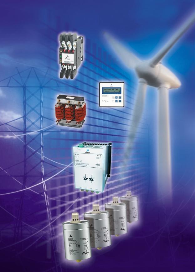
86 86
PhaseCap Premium PFC Capacitors Gas-impregnated n Dry type n Concentric winding n Wavy cut n Triple safety system
 Premium PFC Capacitors General capacitors in cylindrical aluminum cases have been designed for power factor correction in low-voltage plant. Loads like motors and transformers consume active power as well
PhiCap Capacitors for Power Factor Correction
 PhiCap Capacitors for Power Factor Correction Product Profile 2000 http://www.epcos.com PhiCap AC Capacitors for Power Factor Correction General The PhiCap series, is a well approved and reliable EPCOS
POWER CAPACITORS. Cylindrical capacitor standard duty
 Construction Dielectric: Polypropylene film Non PCB, Soft Polyurethane resin Extruded round aluminium can with stud Provided with discharge resistors Overpressure disconnector Features Three phase, delta
PhaseCap HD Capacitors for Power Factor Correction
 Series/Type: Ordering code: Date: 2005-12-14 Version: 3 Content of inside pages of data sheet. Data will be automatically entered into frontpage headlines, headers and footers. Please fill in the table
Power Quality Solutions
 EPCOS Product Profile 2018 Power Quality Solutions www.epcos.com Contents Power Quality Solutions Preview 3 PFC capacitor series overview 6 PQS key components overview 8 Important notes 12 PFC capacitors
PoleCap Capacitors for Power Factor Correction (Outdoor usage)
") PoleCap Capacitors for (Outdoor usage) MKK-Series Series/Type: Ordering code: B25671 Date: June 2005 Version: 1 Content of inside pages of data sheet. Data will be automatically entered into headers and
PoleCap Capacitors for (Outdoor usage) MKK-Series Series/Type: Ordering code: B25671 Date: June 2005 Version: 1 Content of inside pages of data sheet. Data will be automatically entered into headers and
PhaseCap capacitors for power factor correction
 Series/Type: Ordering code: Date: July 2006 Version: 2 Content of header bars 1 and 2 of data sheet will be automatically entered in headers and footers! Please fill in the table and then change the color
Film capacitors Power Factor Correction
 Series/Type: Ordering code: Date: September 2008 Version: 3 Content of header bars 1 and 2 of data sheet will be automatically entered in headers and footers! Please fill in the table and then change the
Capacitors for Power Factor Correction
 Capacitors for Power Factor Correction Series/Type: B25667B The following products presented in this data sheet are being withdrawn. Ordering Code Substitute Product Date of Withdrawal Deadline Last Orders
Film Capacitors Power Factor Correction
 PhaseCap Premium capacitors Series/Type: MKK415-D-6.2-01/MKK480-D-8.3-01/MKK525-D-10.0-01 Ordering code: Date: May 2010 Version: 1 entered in headers and footers! Please fill in the (header 1 + top left
Components for Power Factor Correction
 Components for Power Factor Correction Series/Type: The following products presented in this data sheet are being withdrawn. Ordering Code Substitute Product Date of Withdrawal Deadline Last Orders Last
Film Capacitors Power Factor Correction
 Series/Type: Ordering code: Date: January 2011 Version: 3 entered in headers and footers! Please fill in the Don't change formatting when entering or pasting text in the table and don't add any cell or
Film capacitors Power Factor Correction
 Series/Type: Ordering code: Date: March 2009 Version: 6 Content of header bars 1 and 2 of data sheet will be automatically entered in headers and footers! Please fill in the table and then change the color
Film Capacitors Power Factor Correction
 Series/Type: Ordering code: Date: June 2009 Version: 2 Content of header bars 1 and 2 of data sheet will be automatically entered in headers and footers! Please fill in the table and then change the color
Film capacitors Power Factor Correction
 Series/Type: Ordering code: Date: October 2013 Version: 3 Content of header bars 1 and 2 of data sheet will be automatically entered in headers and footers! Please fill in the table and then change the
Film Capacitors Power Factor Correction
 Series/Type: Ordering code: Date: January 2010 Version: 1 Content of header bars 1 and 2 of data sheet will be automatically entered in headers and footers! Please fill in the table and then change the
Film Capacitors Power Factor Correction
 Series/Type: Ordering code: Date: February 2011 Version: 2 Content of header bars 1 and 2 of data sheet will be automatically entered in headers and footers! Please fill in the table and then change the
Film Capacitors Power Factor Correction
 Series/Type: Ordering code: Date: 2015-07-31 Version: Preliminary PM adding Content of header bars 1 and 2 of data sheet will be automatically entered in headers and footers! Please fill in the table and
Film Capacitors Power Factor Correction
 Series/Type: Ordering code: Date: November 2009 Version: 1 Content of header bars 1 and 2 of data sheet will be automatically entered in headers and footers! Please fill in the table and then change the
multicond Power capacitors Data sheet: multicond
 Power capacitors multicond Monitoring Optimizing Recording multicond are one-phase and three-phase power capacitors for reactive current compensation, developed for networks with many harmonics. Apart
Film Capacitors Power Factor Correction
 Series/Type: PhiCap series with fast-on terminals Ordering code: Date: November 2009 Version: 1 Content of header bars 1 and 2 of data sheet will be automatically entered in headers and footers! Please
Film Capacitors Power Factor Correction
 Series/Type: PhaseCap-series/PhiCap-E-series Ordering code: Date: December 2015 Version: 1 Content of header bars 1 and 2 of data sheet will be automatically entered in headers and footers! Please fill
Film Capacitors Power Factor Correction
 Series/Type: Ordering code: Date: January 2018 Version: 1 Content of header bars 1 and 2 of data sheet will be automatically entered in headers and footers! Please fill in the table and then change the
High Reliable Components for Power Factor Correction and Power Quality
 High Reliable Components for Power Factor Correction and Power Quality It's all about saving your money! Contents Power Factor Correction Capacitors Page 3 Basic Harmonic Filter Reactors Page 11 Standard
DYNACOMP. The top-class reactive power compensator
 DYNACOMP The top-class reactive power compensator Dynacomp vs Electromechanical switching of capacitors Electromechanical switching of capacitors The Dynacomp : the top-class dynamic compensator Transients
- Soft resin impregnated Stacked winding Tripple Safety System
 TORRENT Reactive Power Solutions - Soft resin impregnated Stacked winding Tripple Safety System Parameter Unit Hercules Reference Standard IS 13340 / IEC 60831 Power (Rated Capacitance) Qn 1 30 Tolerance
1 Low-voltage Power-factor Correction capacitors KNK APPLICATION DESIGN
 APPLICATION The KNK capacitors are used for power - factor correction of inductive consumers (transformers, electric motors, rectifiers) in industrial networks for voltages of up to 660 V. DESIGN Cylindrical
LV Capacitors QCap-L series Capacitors for power factor correction
 LV Capacitors QCap-L series Capacitors for power factor correction ABB and power quality ABB is a leader in power and automation technologies that enable utility and industry customers to improve their
LV Capacitor CLMD Reliability for Power Factor Correction
 LV Capacitor CLMD Reliability for Power Factor Correction Reliability for power factor correction CLMD construction The CLMD capacitor consists of a number of wound elements made with a dielectric of metallized
Three Phase Capacitors KNK
 Three Phase Capacitors KNK Features Connection profile Φ 90 and 116 mm 2-16 mm 2, Φ 136 mm 2-25 mm 2 *Use of flexible conductors only with ferrules Capacitors equipped with discharge resistors Rated power
Power Factor Correction
 Power Factor Correction It's all about saving your money! Features that matter n Overcurrent up to 2.2 times rated current n Inrush current up to 300 times rated current n Self-healing type, segmented
Power Factor Correction Capacitors in sheet steel cases
 Power Factor Correction Capacitors in sheet steel cases Power Capacitors type LKN and LKSLT for fixed compensation of, for example, motors and transformers LKN LKSLT Sheet steel case With terminal block
Power Factor Correction Capacitors Type LKT
 Power Factor Correction s LKT E337088 Features that matter: Handles continuous current up to 2.25 / 2.7 times rated current Withstands inrush current up to 375 / 450 times rated current Self-healing type,
Capacitors for Power Electronics
 Capacitors for Power Electronics Series/Type: B2536* The following products presented in this data sheet are being withdrawn. Ordering Code Substitute Product Date of Withdrawal Deadline Last Orders Last
Power Factor Correction Capacitors Type LKT
 Power Factor Correction s LKT E337088 Features that matter: Handles continuous current up to 2.25 / 2.7 times rated current Withstands inrush current up to 375 / 450 times rated current Self-healing type,
High Reliable Components for Power Factor Correction and Power Quality
 High Reliable Components for Power Factor Correction and Power Quality It's all about saving your money! Power Factor Correction Capacitors Type LKT Features that matter: Overcurrent up to 2.2 times rated
Power Factor Correction
 EPCOS Product Profile (India) 2013 Power Factor Correction Power Quality Solutions www.epcos.com The Company: EPCOS India Pvt. Ltd. EPCOS India Private Limited (EIPL) is a Member of TDK-EPC Corporation,
LV Capacitor CLMD03 Power Module Instruction manual
 LV Capacitor CLMD03 Power Module Instruction manual Table of Contents 1 Safety... 3 2 Upon reception... 3 2.1 Inspection on reception... 3 2.2 Storage- transportation handling... 3 3 Hardware Description...
Film Capacitors Power Factor Correction
 Film Capacitors Power Factor Correction Series/Type : DWJ-series Ordering code : DWJxx-xx-x(eg. DWJ0.45-15-3) Date : Jan, 2016 LIJIU JAN 2016. Reproduction, publication and dissemination of this publication,
Film Capacitors Power Factor Correction
 Series/Type : DWJ-series Ordering code : DWJxx-xx-x(eg. DWJ0.25-15-3) Date : May, 2013 WASVAR. Reproduction, publication and dissemination of this publication, enclosures hereto and the information contained
Power Factor Correction Capacitors Harmonic Filter Reactors
 CONSISTENT QUALITY SUPERIOR TECHNOLOGY ENERGY EFFICIENT Harmonic Filter Reactors Tibrewala Electronics Limited About Us As one of the most renowned manufacturers of Capacitors and MPP Film in India, Tibrewala
Power Factor Correction Capacitors Type LKT
 Power Factor Correction s LKT E337088 Features that matter: Handles continuous current up to 2.25 / 2.7 times rated current Withstands inrush current up to 375 / 450 times rated current Environment-friendly,
INSTRUCTION MANUAL. Type SWF. Sine Wave Filters 480 Volts, 60Hz. Page 1 of 14. April 15, 2010: updated capacitor UL File number)
") POWER QUALITY INSTRUCTION MANUAL Type SWF Sine Wave Filters 480 Volts, 60Hz April 15, 2010: updated capacitor UL File number) Page 1 of 14 Contents 1. Introduction & SAFETY 2. Theory of operation 3. Advantage
POWER QUALITY INSTRUCTION MANUAL Type SWF Sine Wave Filters 480 Volts, 60Hz April 15, 2010: updated capacitor UL File number) Page 1 of 14 Contents 1. Introduction & SAFETY 2. Theory of operation 3. Advantage
MADE IN GERMANY. Components for reactive power compensation. Components for reactive power compensation. Power Quality. Reactive power controllers
 Product English Power Quality Components for reactive power compensation MADE IN GERMANY Components for reactive power compensation. Reactive power controllers Filter circuit reactors Capacitor contactors
Power Factor Correction Capacitors Type LKT
 LKT Features that matter: Overcurrent up to 2.2 times rated current Inrush current up to 300 times rated current Self-healing type plus over-pressure disconnector Environmental friendly, dry type, CO2
Power System Solutions (PSS)
") About Power System Solutions mission The Power System Solutions Mission Statement To achieve customer satisfaction by providing innovative solutions to improve upon power quality, energy efficiency, and
About Power System Solutions mission The Power System Solutions Mission Statement To achieve customer satisfaction by providing innovative solutions to improve upon power quality, energy efficiency, and
EMPAC Metal enclosed capacitor bank for wind applications
 EMPAC Metal enclosed capacitor bank for wind applications Introduction The EMPAC is a Metal Enclosed Capacitor Bank suitable for voltages between 1 kv and 36 kv for reactive compensation in MV networks
LV Capacitor Bank APC
 LV Capacitor Bank APC The ABB comprehensive solution for automatic power factor correction: APC standard, reinforced and de-tuned automatic capacitor banks The ABB comprehensive solution for automatic
MODVAR Low voltage reactive power compensation modules Installation manual
 MODVAR Low voltage reactive power compensation modules Installation manual MODVAR Low voltage reactive power compensation modules Before installation, read this manual carefully and keep at the disposal
Chapter 08 Dynamic power factor correction systems (real time PFC) Dynamic power factor correction systems (real time PFC) Optimised, thermal design
 Dynamic power factor correction systems (real time PFC) Optimised, thermal design") Dynamic power factor correction systems (real time PFC) Optimised, thermal design Long service life De-tuned version Minimised grid distortion Dynamic power factor correction systems (real time PFC) Hardly
Dynamic power factor correction systems (real time PFC) Optimised, thermal design Long service life De-tuned version Minimised grid distortion Dynamic power factor correction systems (real time PFC) Hardly
NEW. Heavy Duty Capacitors. Power Factor Correction Capacitors Type LKT. It s all about saving your money! Features that matter:
 LKT Heavy Duty s NEW Overcurrent up to 2.7 times rated current Inrush current up to 450 times rated current Mean Life expectancy: 200,000 h. Up to 100,000 annual switching operations Features that matter:
Medium Voltage. Power Factor Correction Reactive Compensation Harmonic Filters. Electrical Power Quality Management at its best.
 Medium Voltage Power Factor Correction Reactive Compensation Harmonic Filters POWER QUALITY Electrical Power Quality Management at its best. From electricity generation, transmission, thru its distribution
Technical brochure. The Vector series The ABB comprehensive solution for automatic power factor correction
 Technical brochure The Vector series The ABB comprehensive solution for automatic power factor correction 2 Applications The Vector series The Vector series The Vector series is a powerful and compact
Low Voltage Power Factor Corrections
 Low Voltage Power Factor Corrections Capacitors Contents General information on Iskra Capacitors Type Page Introduction 4 1. Single-phase capacitor type KNK5015 230 550 V, 1,67.5 kvar 2. Three-phase capacitors
LV Capacitor Bank APC
 LV Capacitor Bank APC The ABB comprehensive solution for automatic power factor correction: APC standard, reinforced and de-tuned automatic capacitor banks The ABB comprehensive solution for automatic
CAPACITORS FOR POWER ELECTRONICS
 CAPACITORS FOR POWER ELECTRONICS Positive Development in Power Electronics INDEX Page No: 0. CONTENTS 1 1. INTRODUCTION 2 2. APPLICATION 2 3. DEFINITIONS 3 4. CAPACITOR CONSTRUCTION 5 5. CAPACITOR SAFETY
Low voltage capacitors CLMD Improving power factor and enhancing power quality of your network
 PRODUCT BROCHURE Low voltage capacitors CLMD Improving power factor and enhancing power quality of your network s.a. ABB n.v. Power Quality Products Allée Centrale 10 Z.I. Jumet B-6040 Charleroi (Jumet)
Easy Choice for Energy Efficiency
 Easy Choice for Energy Efficiency EasyCan The new generation LV power factor correction capacitors EasyCan The new generation LV power factor correction capacitors What is power factor correction? In electrical
AF series contactors (9 2650)
") R E32527 R E39322 contactors General purpose and motor applications AF series contactors (9 2650) 3- & 4-pole contactors General purpose up to 2700 A Motor applications up to 50 hp, 900 kw NEMA Sizes 00
R E32527 R E39322 contactors General purpose and motor applications AF series contactors (9 2650) 3- & 4-pole contactors General purpose up to 2700 A Motor applications up to 50 hp, 900 kw NEMA Sizes 00
Film Capacitors Power Electronic Capacitors
 Series/Type: Ordering code: Date: Version: 02 Content of header bars 1 and 2 of data sheet will be automatically entered in headers and footers! Please fill in the table and then change the color to "white".
AF series contactors (9 2650)
") R E32527 R E39322 contactors General purpose and motor applications AF series contactors (9 2650) 3- & 4-pole contactors General purpose up to 2700 A Motor applications up to 50 hp, 900 kw NEMA Sizes 00
R E32527 R E39322 contactors General purpose and motor applications AF series contactors (9 2650) 3- & 4-pole contactors General purpose up to 2700 A Motor applications up to 50 hp, 900 kw NEMA Sizes 00
ARTECHE LOW VOLTAGE CAPACITOR BANKS. smartbat LV.
 ARTECHE LOW VOLTAGE CAPACITOR BANKS. smartbat LV. This document may be subject to changes. Contact ARTECHE to confirm the characteristics and availability of the products described here. Moving together
Automatic COSYS PFC. Automatic power factor correction system NEW
 Automatic COSYS PFC Automatic power factor correction system NEW cosys_178_a_1_x_cat cosys_178_a_1_x_cat appli_xxx_a  Function Your reactive energy consumption vary depending on the type and using conditions
NXPLUS C Single busbar. Maintenance-free for lifetime
 NXPLUS C Single busbar Maintenance-free for lifetime Energy Distribution Welcome! Page 2 Content Overview Technical data Typicals Panel design Circuit-Breaker panel Busbar Operation Metering Low-voltage
FRANKE. Power Factor Correction GMKP ENERGY. GMKPg Low Voltage Capacitors by Gas Technology Save energy and reduce carbon dioxide emission!
 for a better power! Power Factor Correction Low & Medium Voltage System by Gas Technology Save energy and reduce carbon dioxide emission! LTD. Http://frankegmkp.com Email:info@frankegmkp.com German Brand
AC Capacitors Safety and Application Manual
 Motors Automation Energy Transmission & Distribution Coatings AC Capacitors Safety and Application Manual Safety and Application Manual Serie: AC Capacitors Language: English Document nº: 10005056250
Matrix APAX. 380V-415V 50Hz TECHNICAL REFERENCE MANUAL
 Matrix APAX 380V-415V 50Hz TECHNICAL REFERENCE MANUAL WARNING High Voltage! Only a qualified electrician can carry out the electrical installation of this filter. Quick Reference ❶ Performance Data Pages
High Density DC Film Capacitors
 Product Selector Guide September 2013 Issue 1 CUENT AND CAPACITANCE AS YOU NEED IT The IXYS UK E50 PK16 range of capacitors can be used for the assembly of low inductance DC buffer circuits and DC filters;
Energy sector DC LINK CAPACITORS AND SNUBBERS
 Energy sector DC LINK CAPACITORS AND SNUBBERS DC link APPLICATIONS Hybrid vehicles Wind plants Solar power plants Electric energy generation from sea waves Medical equipment Industrial equipment Car electronics
Motor Running & Motor Starting Lamp Power Factor
 Motor Running & Motor Starting Lamp Power Factor Capacitors 2 Contents General information on Iskra Capacitors Type Construction of capacitors Page KNM 70xx 80xx 90xx KNM 12xx 22xx 32xx KNM31xx metallized
LOW VOLTAGE CAPACITORS AND CAPACITOR BANKS. Capacitors department
 LOW VOLTAGE CAPACITORS AND CAPACITOR BANKS Capacitors department I Selecting the reactive energy compensation system 3 II Selecting the capacitor type 4 III ALPIVAR 6 IV V VI VII VIII SPECIAL RANGES 25
Sr. No. Details Page No. 1 MV Capacitor Unit Drawings 3. 2 Technical Perticular for Capacitor Unit 4. 3 MV Surge Capacitor Unit Drawings 6
 INDEX : Sr. No. Details Page No. 1 MV Capacitor Unit Drawings 3 2 Technical Perticular for Capacitor Unit 4 3 MV Surge Capacitor Unit Drawings 6 4 Technical Perticular for Surge Capacitor Unit 7 5 MV Energy
High Frequency SineWave Guardian TM
 High Frequency SineWave Guardian TM 380V 480V INSTALLATION GUIDE FORM: SHF-IG-E REL. January 2018 REV. 002 2018 MTE Corporation High Voltage! Only a qualified electrician can carry out the electrical installation
NFC. (Varistor Type NFC)
") NFC (Varistor Type NFC) Type NFC Varistors are made of semiconductor ceramic materials composed mainly of zinc oxide. They have nonlinear resistance that changes as a function of applied voltage. It has
NFC (Varistor Type NFC) Type NFC Varistors are made of semiconductor ceramic materials composed mainly of zinc oxide. They have nonlinear resistance that changes as a function of applied voltage. It has
Reactive Energy Management
 Power Factor Correction Reactive Energy Management Low Complete reference of power ratings and application tables for 50 Hz networks Guide 2011 Increase in Power Availability Enhanced safety Improve your
Installation and maintenance instructions for thyristor modules TSM-LC series
 Film Capacitors Installation and maintenance instructions for thyristor modules TSM-LC series Series/Type: Ordering code: Thyristor modules TSM-LC B44066T.E402 Content of header bars 1 and 2 of data sheet
Film capacitors Power electronic capacitors
 MKP PEC DC Series/Type: B2562* Ordering code: Date: June 2010 Version: 3.2 Content of header bars 1 and 2 of data sheet will be automatically entered in headers and footers! Please fill in the table and
REFERENCE MANUAL FORM: MX-TRM-E REL REV MTE
 Matrix APAX 380V-415V 50Hz TECHNICAL REFERENCE MANUAL FORM: MX-TRM-E REL. September 2014 REV. 002 2014 MTE Corporation WARNING High Voltage! Only a qualified electrician can carry out the electrical installation
Dynamic PFC:Thyristor Modules TSM Series
 Dynamic PFC:Thyristor Modules TSM Series P o w e r Q u a l i t y S o l u t i o n s www.epcos.com/pfc The collection of PQS is a library with in-depth information on PFC applications, case studies and reference
C1000 Series Automatic Cap Bank
 C1000 Series Automatic Cap Bank Metal Enclosed - Medium Voltage Capacitors Assemblies Fixed / Auto Medium Voltage 5, 15, 25 and 35 kv Class Customized to your specifications The Reactive Power Solution
Trifazni kondenzatorji KNK
 Trifazni kondenzatorji KNK Features Vezava profile Φ 90 and 116 mm 2-16 mm 2, Φ 136 mm 2-25 mm 2 *Use of flexible conductors only with ferrules Capacitors equipped with discharge resistors Nazivna moč
Power Factor Correction
 Motors Automation Energy Transmission & Distribution Coatings USA3846PF 08/12 WEG www.weg.net Electric Improving Plant Life with Capacitors Reduce Utility Costs - improved Power Factor can reduce or eliminate
OTCF. Grid Solutions. Capacitor Voltage Transformers 72.5 kv to 800 kv. Quality Product Design. Seismic Withstand Capability.
 GE Grid Solutions OTCF Capacitor Voltage Transformers 72.5 kv to 800 kv In high and extra high voltage transmission systems, capacitor voltage transformers (CVTs) are used to provide potential outputs
Caps unlocked. ABB s new QCap cylindrical capacitor improves power factors
 ABB s new QCap cylindrical capacitor improves power factors RAYMOND MA-SHULUN, CYRILLE LENDERS, FRANCOIS DELINCÉ, MARIE PILLIEZ Reactive power is a major concern for both industries and utilities. It impacts
Power Factor Correction
 Power Factor Correction Medium Voltage Automatic Capacitor Bank Save energy and reduce Carbon dioxide emission! FRANKE GMKP LTD. Http://www.frankegmkp.com 17015 Berlin,Germany Email:info@frankegmkp.com
Modifiable TITAN Horizontal Motors Accessories and Modifications
 36. Rotor, Standard And Optional Construction Standard rotor construction of 449, 5000 and 5800 frame TITAN products is typically die-cast aluminum. 720 RPM and slower is typically fabricated aluminum.
Dimensions mm. IMax Multiplier 1kHz 10kHz. Ambient Temperature. Fixing symbol code
 UPGRADE! MLC Cylindrically-Shaped Metallized Polypropylene Fim Capacitos Features Cylindrically-shaped capacitor with big capacitance for wind & solar power inverters, other inverters, chopper control
AIR CORE REACTORS. Phoenix Electric Corporation
 AIR CORE REACTORS Phoenix Electric Corporation PHOENIX ELECTRIC CORPORATION designs and manufactures Dry Type Air Core Reactors for operation on systems rated through 800 kv. All reactors are custom designed
Matrix AP 400V 690V INSTALLATION GUIDE. Quick Reference. ❶ How to Install Pages 6 20 ❷ Startup/Troubleshooting Pages WARNING
 Matrix AP 400V 690V INSTALLATION GUIDE FORM: MAP-IG-E REL. May 2017 REV. 002 2017 MTE Corporation WARNING High Voltage! Only a qualified electrician can carry out the electrical installation of this filter.
CP Automatic capacitor bank
 CP 254 - Automatic capacitor bank STE-CP254_V2_général.doc Page 1 CP 254 - General presentation CP 254 is a range of MV capacitor banks designed to be used in electrical networks up to 36kV. The capacitor
Film Capacitors Power Electronic Capacitors
 Film Capacitors Power Electronic Capacitors Series/Type: Ordering code: * Date: September 2014 Version: 9 Content of header bars 1 and 2 of data sheet will be automatically entered in headers and footers!
Film Capacitors - Power Electronic Capacitors
 Series/Type: Ordering code: Date: Version: 01 Content of header bars 1 and 2 of data sheet will be automatically entered in headers and footers! Please fill in the table and then change the color to "white".
Film Capacitors Power Factor Correction
 Series/Type: Ordering code: Date: August 2010 Version: 5 entered in headers and footers! Please fill in the Don't change formatting when entering or pasting text in the table and don't add any cell or
Smart Energy & Power Quality Solutions. Main catalogue 2012/2013. Power Factor Correction / Power quality
 Smart Energy & Power Quality Solutions Main catalogue 2012/2013 Power Factor Correction / Power quality Power Quality Solutions Power quality and supply reliability are extremely important in the modern
CLMD Low-voltage capacitors for reliable power factor correction
 CLMD Low-voltage capacitors for reliable power factor correction Reliability for power factor correction CLMD construction The CLMD capacitor consists of a number of wound elements made with a dielectric
Automatic capacitor banks
 NEW ZEALAND WWW.LPINZ.CO.NZ Unit 6/22 Moselle Ave, Henderson, Auckland, New Zealand PO Box 21-872, Henderson, Auckland, New Zealand Phone:+64 9 833 5749 Email:info@LPINZ.co.nz Web: www.lpinz.co.nz Automatic
Type SIMOPRIME A4, up to 24 kv, Air-Insulated Medium-Voltage Switchgear
 Circuit-Breaker www.siemens.com/energy Switchgear Type SIMOPRIME A4, up to 24 kv, Air-Insulated Medium-Voltage Switchgear s Technology Circuit-Breaker Switchgear Type SIMOPRIME, up to 17.5 kv, Air-Insulated
Appendix: Safety and application notes for... 15
 Contents Safety... 2 Warnings... 2 Symbols used in this manual... 2 Operator s safety... 2 Avoid filter module damage... 2 DC-link resonance... 2 Description... 3 Description... 3 Ordering numbers, 380-415
HV Compensation & Filtering Products
 GE Grid Solutions HV Compensation & Filtering Products Providing Power Quality and Energy Efficiency High Voltage (HV) reactive power compensation and harmonic filtering solutions help customers to improve
Film Capacitors Power Factor Correction
 Series/Type: Ordering code: Date: June 2012 Version: 3 Content of header bars 1 and 2 of data sheet will be automatically entered in headers and footers! Please fill in the table and then change the color