Schematic VCC J1 1 CON1 +5V D26 D25 D7 D8 D9 D10 D11 D12 D19 D20 D21 D22 D23 D24 D1 D2 D3 D4 D5 D6 D13 D14 D15 D16 D17 D18 R4 100R R2 100R R6 100R
|
|
|
- Holly Craig
- 6 years ago
- Views:
Transcription
1 Schematic +5V S D1 D2 D3 D4 D5 D6 D7 D8 D9 D10 D11 D12 D19 D20 D21 D22 D23 D24 D13 D14 D15 D16 D17 D18 D25 D26 R1 4K7 R2 100R Q PNP C1 47uF R3 4K7 R4 100R Q PNP C2 47uF R5 4K7 R6 100R Q PNP C3 47uF GND VCC J1 1 CON1 J2 1 CON1 GND GND GND GND
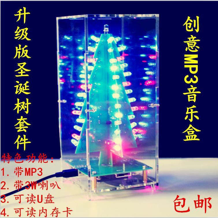
2 With Music Version Introduction Note: Only support mp3 format music. Package list: Parameter Numeral on board Note Specification Qua. 1uf (105) C1, C2, C3, C5, C6, C7 No direction 0805 capacitors 7 104(0.1uf) C4 C11 No direction 0805 capacitors 2 100PF C9 No direction 0805 capacitors 2 1K(102) R1 R2 R3 R4 No direction 0805 Resistors 5 4.7R(4R7) R5 No direction 0805 capacitors 2 0R(000) R6 No direction 0805 capacitors 2 20K(203) R7 No direction 0805 capacitors 2 47K(473) R8 No direction 0805 capacitors 2 22K(223) R9 No direction 0805 capacitors 2 33K(333) R10 No direction 0805 capacitors 2 51K(513) R11 No direction 0805 capacitors 2 TF socket TF1 TF card socket 1 16pin chip U1 Directional SO-16 SMD B U2 Directional SO-8 SMD 1 Min USB USB2 USB socket 1 Insert U disk USB1 USB socket 1 220UF/16V C8 C10 Directional Electrolytic capacitors 2 Tact Switch S1 S2 S3 Lateral leg 6*6 *10 3 3mm pink led LED1, LED2, LED3, LED4 Directional 3mm led 5 Audio port P1 Audio socket 1 Speaker Interface Self-locking switch SP1 3W speaker 1 SW1 Switch 1 100R A:R2, R4, R6 B:R2, R4, R6 No direction 0.25W Plug-resistance 7

3 4.7K A:R1, R3, R5 B:R1, R3, R5 No direction 0.25W Plug-resistance 7 47uf/16v A:C1 C2 C3 B:C1 C2 C3 Directional Plug-in electrolytic capacitors 6 S9014 A:Q1, Q2, Q3 B:Q1, Q2, Q3 Directional Transistor 6 led A:D1~D26 B:D1~D26 Directional 5mm RGB led Soldering baseboard (note: all the components on the base must be soldered to the back) 1) Back side of baseboard
, there is no")

4 2) Soldering 1uf capacitor (105), there is no direction 3) Soldering SMD resistor capacitor (no direction)
 5) Soldering TF")


5 4) Soldering U1, U2 chip (direction) 5) Soldering TF socket (needs more careful when soldering, do not short circuit) 6) Soldering button (note soldering on the back side)
 After soldering the")
6 7) Four corners LED soldering (directional), need to pay attention when soldering, can not be soldered two pins at the same time, otherwise it will burn led 8) After soldering the baseboard
 Soldering resistance 100R (no direction, as the picture")
7 2. Christmas tree A, B board soldering (method is the same) 1) Soldering resistance 100R (no direction, as the picture show)
8 2) Soldering 4.7K resistor (no direction, as the picture show)
 4) Soldering 47uf electrolytic capacitors")

9 3) Soldering 9014 (there is a direction, as the picture show) 4) Soldering 47uf electrolytic capacitors (directional, long foot is positive) 5) Soldering LED (directional, long foot is positive, need to pay attention when
 6) After soldered A and B")
10 soldering, can not be soldered two pins at the same time, otherwise it will burn led) 6) After soldered A and B boards
 3.")
11 7) Soldering top led (Note: need to combine A and B plate at first, long foot is positive) 3. A, B board and backplane connection diagram:

: 2) the \"-\" corresponding to")
12 1) After A and B board combined, the "+" corresponding to the "+" sign (while watching from the self-locking switch): 2) the "-" corresponding to the "-" sign


13

14 4. The assembly of the housing 1) A method of assembling the housing (Fixing the screw nut, and put into the screw)

15 2) First assembled four faces

16 3) fixed plate

17 4) Install the base plate
18 5) Finish
IDC-136II-KIT 136kHz DC RX Assembly Guide
 IDC-136II-KIT 136kHz DC RX Assembly Guide ICAS Enterprises May 2 nd,2016 The IDC-136II-KIT is a 136kHz direct conversion receiver. Most of the SDR software can be used with this receiver. It is quite easy
IV-3 VFD Shield for Arduino. Assembly Manual
 June 2014 Table of Contents 1 Overview Features Applications 3 3 3 2 Assembly Hints 4 3 PCB Overview 5 4 Circuit Diagram 6 5 Assembly Diodes and IC socket Electrolytic capacitors Ceramic capacitors 10K
IV-11 VFD tube clock Assembly instructions v1.2.2
 IV-11 VFD tube clock Assembly instructions v1.2.2 Designer: Website: E-mail: Yan Zeyuan. China http://www.nixieclock.org yanzeyuan@qq.com 2017-01-26 NCH Attention Attention: Warning: Warning: Warning:
RGB Alarm Clock. -Color Alarm Clock-
 RGB Alarm Clock -Color Alarm Clock- Table of Contents Preamble:...2 List of parts...3 Components...5 Parts and belongings...5 Clock Board Assembly...8 Identification of SMD parts:...0 The power supply
Ljunggren Audio Roll Your Own Penta
 Ljunggren Audio Roll Your Own Penta Version: Penta 1.0 Bills Of Material Bold = PCB1, The rest = PCB2 Type Parts Des cription Pow er header Qty Value 1 2x5pin POWER Euro pow er connector Jack 1 3.5mm J1,
ASSEMBLY INSTRUCTIONS FOR NEW FK109 4 LED Railroad Crossing Flasher Kit WITH ADJUSTABLE FLASHING SPEED CONTROL with 4 Red 3mm Leds
 ASSEMBLY INSTRUCTIONS FOR NEW FK109 4 LED Railroad Crossing Flasher Kit WITH ADJUSTABLE FLASHING SPEED CONTROL with 4 Red 3mm Leds Description: Very easy to build, The FK109 Led Flasher kit makes the perfect
Assembly Manual for New Control Board 22 June 2018
 Assembly Manual for New Control Board 22 June 2018 Parts list Arduino 1 Arduino Pre-programmed 1 Faceplate Assorted Header Pins Full Board Rev A 9 104 capacitors 1 Rotary encode with switch 1 5-volt regulator
MANSON ENGINEERING INDUSTRIAL LTD. SERVICE MANUAL FOR SPS-9400
 MANSON ENGINEERING INDUSTRIAL LTD. SERVICE MANUAL FOR SPS-9400 CONTENTS 1. PRODUCTION SPECIFICATION P.1 2. ALIGNMENT PROCEDURE P.2 3. TROUBLE SHOOTING P.5 4. CHANGE OF ELECTRONIC COMPONENTS P.6 5. DIAGRAMS
BUMP AND SPIN KIT ESSENTIAL INFORMATION. Version 1.0 PROGRAM AND DESIGN YOUR OWN BUGGY WITH THIS
 ESSENTIAL INFORMATION BUILD INSTRUCTIONS CHECKING YOUR PCB & FAULT-FINDING MECHANICAL DETAILS HOW THE KIT WORKS PROGRAM AND DESIGN YOUR OWN BUGGY WITH THIS BUMP AND SPIN KIT Version 1.0 Build Instructions
Electronic Dice Kit MitchElectronics 2019
 Electronic Dice Kit MitchElectronics 2019 www.mitchelectronics.co.uk CONTENTS Schematic 3 How It Works 4 Materials 5 Construction 6 Important Information 7 Page 2 SCHEMATIC Page 3 SCHEMATIC EXPLANATION
Ljunggren Audio Roll Your Own Optodist
 Ljunggren Audio Roll Your Own Optodist Version: Optodist/VCA.0 Bill Of Material TYPE PART VALUE PCS NOTE Resistor R,R 0R Resistor R5,R0 K Resistor R3,R4 0K Resistor R,R9 68K Resistor R 00K Resistor R3
ECO-6 & Installation Manual
 ECO-6 & Installation Manual For the SPA4-RFR Upgrade Kit To upgrade SPA4 amplifiers v1.00 & v1.01 to v2.0 Some sections also apply to the PA1, PA2, and PA3 14 August 2015 2015 by Ralph Hartwell Spectrotek
~Dashboard Digital Voltmeter~
 ~Dashboard Digital Voltmeter~...November, 2002 This project is helpful to anyone who drives an automobile. I had found this project at the local libary... in an old publication. I made it and it worked
Parts List DIY-81 rev 1. Capacitors. DIY-81 Project Parts list rev 1
 Electrolytic C100 100 25 Axial 8 x 100uF/25V Axial C101 150 16 Axial 8 x 150uF/16V Axial C102 150 16 Axial 2 x 470uF/16V Radial C18 470 16 Radial C103 150 16 Axial C104 150 16 Axial C106 100 25 Axial C105
SP6121 Demo Board Manual
 SP6121 Demo Board Manual FEATURES DC/DC Synchronous Buck Converter for Distributed Power Systems. SIP design provides complete, ready to use solutions for : Vin=3.0-7.0V Vout=1.25-5.0V I out=8.0a (no air
openqrp Transceiver Parts List By Functional Section 1/11/2014 Using openqrp PC Board Rev D, 40M Version
 openqrp Transceiver Parts List By Functional Section 1/11/2014 Using openqrp PC Board Rev D, 40M Version Section 1 AGND Schematic Page 2 R37 [I8] 10K 1/8W Resistor (Brown Black Orange) R38 [J9] C80 [J9]
VALVE POWER AMPLIFIER SUPPLEMENT
 STEP BY STEP CONSTRUCTION MANUAL FOR THE UL40-S2P VALVE POWER AMPLIFIER SUPPLEMENT to the UL 40-S2 manual 1 COMPONENTS UL 40-S2P CODE VALUE TYPE QUANTITY PRINTING Resistors R2 4,7kΩ 1W metalfilm 2 ye-vi-blk-br-br
ez1081pre Mic Amplifier - Assembly manual [ Colourbook Issue 1]
![ez1081pre Mic Amplifier - Assembly manual [ Colourbook Issue 1]](/thumbs/90/103906919.jpg "ez1081pre Mic Amplifier - Assembly manual [ Colourbook Issue 1]") ez1081pre Mic Amplifier - Assembly manual [ Colourbook Issue 1] ez1081pre Colourbook Contents. Section 1 - Colourbook assembly guide Section 2 - Setup and Calibration Section 3 - Schematics diagrams and
ez1081pre Mic Amplifier - Assembly manual [ Colourbook Issue 1] ez1081pre Colourbook Contents. Section 1 - Colourbook assembly guide Section 2 - Setup and Calibration Section 3 - Schematics diagrams and
2xVCX version 1.0. Calibration instructions can be found on the last page. Capacitor bypass MLCC X7R mm pin pitch
 Produced by: Roll Your Own ljunggrenaudio.com Schematic & PCB Design by: KYMATICA DEVICES www.kymatica.com xvcx version.0 Bills Of Material Bold = PCB C C C3 C4 C5 C6 C7 C8 C9 C0 C C C3 C4 CON D D D3 D4
EMG SpikerShield v1.2 Instructions
 EMG SpikerShield v1.2 Instructions Prepare yourself. In 2-4 hours, you will have built your own Arduino compatible EMG SpikerBox, so you can control robots and anything you wish with your EMG muscle activity.
DIY Synth Kit - Manual
 DIY Synth Kit - Manual Welcome to the DIY Synth - Manual This is a step-by-step guide to making your own electronic Synth. All the equipment you ll need to make your synth is your DIY Synth kit and of
WHDTS Smart Car Kit D2-5 Electric Soldering DIY Kits
 D2-5 Smart Car Kit Intructions Foreword Thank you for choosing the D2-5 smart car kit. This kit gives you an initial understanding of the principles and techniques of automatic control. We hope you can
100W SUBWOOFER KIT. Total solder points: 383 Difficulty level: beginner advanced K8077 ILLUSTRATED ASSEMBLY MANUAL
 100W SUBWOOFER KIT Powerful bass from a small cabinet thanks to the dual speaker principle Total solder points: 383 Difficulty level: beginner 1 2 3 4 5 advanced K8077 ILLUSTRATED ASSEMBLY MANUAL H8077IP-1
MOTHMAN FUZZ ASSEMBLY INSTRUCTIONS RECOMMENDED TOOL AND SUPPLY LIST MOTHMAN FUZZ KIT PARTS LIST
 MOTHMAN FUZZ ASSEMBLY INSTRUCTIONS Thank you for purchasing the J201 Clean Boost Pedal Kit from Mammoth Electronics! This is a intermediate level kit that and we have made every effort to make the assembly
HW-8-LM386 Audio Amplifier Board Assembly Instructions
 This LM386 based audio amplifier kit was designed to replace the small audio amplifier board in the Heathkit HW-8 transciever. The result is the ability to drive regular modern day 8 ohm headphones or
Assembly Instructions for the KA Electronics Flat MM Phono Preamplifier
 Assembly Instructions for the KA Electronics Flat MM Phono Preamplifier Install IC sockets Flat MM Phono Preamp PC Board Stuffing Guide Place the PC Board on the bench silkscreen side face up. Drop six
Service Manual - CD-303MP
 R Service Manual - CD-303MP CD-303MP WiWi Industries Limited Engineering Department Bill of Materials 1 001-0000S-B90 P.C.B FILTER BOX 1 2 001-3900S-P90 P.C.B CD-3900 MAIM BOARD 1 3 002-01140-A00 I.C LA1140
D Gillespie Designs. PC-10A Amplifier Board. Installation Guide. D Gillespie Designs
 PC-10A Amplifier Board Installation Guide The PC-10A eyelet and mounting hole locations are consistent with the original Dynaco PC-10 circuit board. Installing the PC-10A is exactly the same as the original
Build Instructions and User Guide
 Build Instructions and User Guide Getting Started To build the Rock Drill 4069 you will need: Solder Wire Cutters Soldering Iron Small pliers The kit is suitable for beginners or more experienced builders
CAPI BB2521 Build Guide & BOM
 This is a very simple build. I only have a few tips and things to look out for. I do recommend following these steps due to the diode/transistor relationship. 1. Install the three ceramic caps. If you
DIY Synth Kit - Manual STUTTER SYNTH
 DIY Synth Kit - Manual STUTTER SYNTH Welcome to the DIY Synth - Manual This is a step-by-step guide to making your own electronic Synth. All you will need is your hands and your DIY Synth kit which includes
3A L.D.O. VOLTAGE REGULATOR (Adjustable & Fixed)
") FEATURES Output Current of 3A Fast Transient Response 0.04% Line Regulation 0.2% Load Regulation Internal Thermal and Current Limiting Adjustable or Fixed Output oltage(1.5, 1.8, 2.5, 3.3, 5.0) Surface
FEATURES Output Current of 3A Fast Transient Response 0.04% Line Regulation 0.2% Load Regulation Internal Thermal and Current Limiting Adjustable or Fixed Output oltage(1.5, 1.8, 2.5, 3.3, 5.0) Surface
WHDTS Smart Intelligent Robot Tracking Car D2-5 Electric Suite DIY Kits
 . Introduction There is a 6mm wide black runway in the white field.this tracking car can drive along the black runway automatically.no matter how the runway is bent, the car can be driven automatically.
Application Note: Assembling the DHT Coleman Regulator for Transmitting DHTs: 2.5A to 3.6A. Please Read this Note together with Andht01 [PDF Manual]
![Application Note: Assembling the DHT Coleman Regulator for Transmitting DHTs: 2.5A to 3.6A. Please Read this Note together with Andht01 [PDF Manual]](/thumbs/94/120539265.jpg "Application Note: Assembling the DHT Coleman Regulator for Transmitting DHTs: 2.5A to 3.6A. Please Read this Note together with Andht01 [PDF Manual]") Application Note: Assembling the DHT Coleman Regulator for Transmitting DHTs: 2.5A to 3.6A. Please Read this Note together with Andht01 [PDF Manual] 1. Parts you will need (NOT supplied in the kit): Lyrima,
Application Note: Assembling the DHT Coleman Regulator for Transmitting DHTs: 2.5A to 3.6A. Please Read this Note together with Andht01 [PDF Manual] 1. Parts you will need (NOT supplied in the kit): Lyrima,
HW-8-LM386 Audio Amplifier Board Assembly Instructions
 This LM386 based audio amplifier kit was designed to replace the small audio amplifier board in the Heathkit HW-8 transciever. The result is the ability to drive regular modern day 8 ohm headphones or
1. DISASSEMBLY AND REPLACEMENT (#1~ #22) 2. PARTS LIST 3. P.C.B. CIRCUIT DIAGRAM 4. C.P.U BLOCK DIAGRAM AND PIN ASSIGNMENT 5.
 2. PARTS LIST 3. P.C.B. CIRCUIT DIAGRAM 4. C.P.U BLOCK DIAGRAM AND PIN ASSIGNMENT 5.") 1. DISASSEMBLY AND REPLACEMENT (#1~ #22) 2. PARTS LIST 3. P.C.B. CIRCUIT DIAGRAM 4. C.P.U BLOCK DIAGRAM AND PIN ASSIGNMENT 5. MEASUREMENT VOLTAGE CHECK MOTOR OPERATION CHECK PRINT HEAD RESISTANCE MEASUREMENT
1. DISASSEMBLY AND REPLACEMENT (#1~ #22) 2. PARTS LIST 3. P.C.B. CIRCUIT DIAGRAM 4. C.P.U BLOCK DIAGRAM AND PIN ASSIGNMENT 5. MEASUREMENT VOLTAGE CHECK MOTOR OPERATION CHECK PRINT HEAD RESISTANCE MEASUREMENT
THREE PHASE FAULT ANALYSIS WITH AUTO RESET ON TEMPORARY FAULT AND PERMANENT TRIP OTHERWISE
 THREE PHASE FAULT ANALYSIS WITH AUTO RESET ON TEMPORARY FAULT AND PERMANENT TRIP OTHERWISE ABSTRACT The project is designed to develop an automatic tripping mechanism for the three phase supply system.
Total solder points: 187 Difficulty level: beginner advanced. Code lock K6400 ILLUSTRATED ASSEMBLY MANUAL
 Total solder points: 187 Difficulty level: beginner 1 2 3 4 5 advanced Code lock K6400 Ged rid of those old fashioned keys ILLUSTRATED ASSEMBLY MANUAL H6400IP-2 Features & Specifications Features: More
AMS1117 1A Adjustable / Fixed Low Dropout Linear Regulator
 1A Adjustable / Fixed Low Dropout Linear Regulator Description The is a series of low dropout voltage regulators which can provide up to 1A of output current. The is available in six fixed voltage, 1.2,
Manual Version November 2011
 Manual Version 2.2 - November 2011 This Version supports the latest Interstage version using the T-195 Mains TX CH-170 220uf 4 pole cap New POWER SUPPLY wiring strategy Copper Insert plate and CMC valve
Audio Regenesis. Power Supply Capacitor Replacement Board. Dynaco PAS 2, 3, 3X Preamplifiers. Installation Guide. For. Pacific Audio Regenesis
 Audio Regenesis Power Supply Capacitor Replacement Board For Dynaco PAS 2, 3, 3X Preamplifiers Installation Guide Pacific Audio Regenesis www.audioregenesis.com Thank you for choosing our power supply
BUMP AND SPIN KIT TEACHING RESOURCES. Version 1.1 PROGRAM AND DESIGN YOUR OWN BUGGY WITH THIS
 TEACHING RESOURCES SCHEMES OF WORK DEVELOPING A SPECIFICATION COMPONENT FACTSHEETS HOW TO SOLDER GUIDE PROGRAM AND DESIGN YOUR OWN BUGGY WITH THIS BUMP AND SPIN KIT Version 1.1 Index of Sheets TEACHING
QRPGuys Digital RF Probe
 QRPGuys Digital RF Probe First, familiarize yourself with the parts and check for all the components. If a part is missing, please contact us and we will send one. This kit contains seventeen 1206 size
Linear Stepper Driver v0.9.2 Assembly Instructions
 Linear Stepper Driver v0.9.2 Assembly Instructions Here's what's included in the kit: 1x Printed Circuit board 1x Heatsink bracket 5x 0.1uF capacitors 1x 6-pin ISP header 1x 10-pin configuration header
802C System Controller Original and SMD Version
 802C System Controller Original and SMD Version Units with serial numbers beginning with 100000 are the original 802C's. Units with serial numbers beginning with 200000 are the new SMD 802C's. 1997 Bose
WIRING THE HEATER POWER SUPPLY
 WIRING THE HEATER POWER SUPPLY Fig. 14 13/14 Take the longer PS board (with the 47R resistors and the fuse) and, using M3x6 screws, fix it to the chassis to the left of the mains transformer. The diodes
Soldering Pi2Go Lite. Soldering the Line-Follower PCB
 Soldering Pi2Go Lite First check which version of the main PCB you have. It is marked above the left motor "Pi2Go-Lite v1.x". There are minor changes to some parts of the build. v1.0 (initial release)
Total solder points: 93 Difficulty level: beginner advanced 10 LED MONO VU METER K4304 ILLUSTRATED ASSEMBLY MANUAL
 Total solder points: 93 Difficulty level: beginner 1 2 3 4 5 advanced 10 LED MONO VU METER K4304 Add a visual readout to your existing or new equipment. ILLUSTRATED ASSEMBLY MANUAL H4304IP-1 Features &
Assembly Manual for ISDR-136-KIT
 Assembly Manual for ISDR-136-KIT ICAS Enterprises Last Updated March 21 st, 2012 This SDR receiver kit is intended for the 136kHz band. The kit utilizes DIP IC components (no SMD) so that even a beginner
MANSON ENGINEERING INDUSTRIAL LTD. SERVICE MANUAL FOR SPS-9400
 MANSON ENGINEERING INDUSTRIAL LTD. SERVICE MANUAL FOR SPS-9400 CONTENTS 1. PRODUCTION SPECIFICATION P.1 2. ALIGNMENT PROCEDURE P.2 3. TROUBLE SHOOTING P.5 4. DIAGRAMS P.6 4.1 SCHEMATICS P.6 4.2 PCB SILKSCREEN
D6, D7, D8, D9, D12, D13, D14, D15, D16, D17, D18, D19. Schottky rectifier diode. 1N5817-1N5819 or SB130
 Roll Your Own ljunggrenaudio.com Altered States version 1.0 Bills Of Material Qty Value 12 1N4148 2 1N5818 4 1N750 4.7V 4 220p Device Diode Diode Zener diode Capacitor 30 100n 4 15p 8 560p 1 5x2 pin Capacitor
BehringerMods.com. Instructions for modification of Behringer DCX analog inputs and outputs
 BehringerMods.com Instructions for modification of Behringer DCX analog inputs and outputs The following instructions will cover the details of fully modifying a unit with analog output and analog input
AT1084 5A Low Dropout Positive Voltage Regulator
 FEATURES DESCRIPTION Three-Terminal Adjustable or Fixed Output Output Current of 5A Low Dropout 1.3V at 5A Output Current Line Regulation: 0.04% Load Regulation: 0.2% Fast Transient Response OCP & OTP
synthcube 291 VCF (buchla / verbos circuit realized by dustin stroh) module documents v2.0 06/20/2014 PCB rev 2.0 Errata:
 module documents v2.0 06/20/2014 PCB rev 2.0 Errata:") synthcube 291 VCF (buchla / verbos circuit realized by dustin stroh) module documents v2.0 06/20/2014 PCB rev 2.0 Errata: copyright 2012 synthcube.com Page 1 Circuit Description A discussion thread about
synthcube 291 VCF (buchla / verbos circuit realized by dustin stroh) module documents v2.0 06/20/2014 PCB rev 2.0 Errata: copyright 2012 synthcube.com Page 1 Circuit Description A discussion thread about
SM361 RIG SWITCH CONSTRUCTION MANUAL
 SM361 RIG SWITCH CONSTRUCTION MANUAL Document ver 1, For software release ver 1.1 May 27, 2016 Controls the power of 12V equipment while a vehicle is in use Product Development by: SM361 RIG SWITCH OVERVIEW
Brand :Airwell Model : GCNG 9 / R407C
 Brand :Airwell Model : GCNG 9 / R407C Product Number : 7SP06374 Version : Cooling only 230//50 Internal number : 357 2 43322 Baflfe 7 45960 Bottom 5 20407 Cable clamp 3 457990 Capacitor 2uF/450V 9 455797
FEATURES DESCRIPTION APPLICATIONS TYPICAL APPLICATION PIN OUT & MARKING. Max.2A Li-ion Switching Charger IC
 DESCRIPTION The is a 2A Li-Ion battery switching charger intended for 5V adapters. Low power dissipation, an internal MOSFET and its compact package with minimum external components requirement makes the
Lab 4.4 Arduino Microcontroller, Resistors, and Simple Circuits
 Lab 4.4 Arduino Microcontroller, Resistors, and Simple Circuits A microcontroller is a "brain" of a mechatronic system that interfaces sensors with a computer. Microcontrollers can perform math operations,
mb808 FAB manual
 mb808 FAB manual http://www.eight-oh-eight.org Step one: Power Supply: ATTENTION: You will be dealing with AC mains voltages in this part of the build, if you are not careful you can injure yourself, or
K3500 MULTIFUNCTION CAR COURTESY LIGHT. Specifications
 Total solder points: 87 Difficulty level: beginner 1 2 3 4 5 advanced MULTIFUNCTION CAR COURTESY LIGHT K3500 Never look for the ignition switch in the dark again. Specifications switch-off delay: adjustable
CLASSIC PEDAL KIT. Assembly Instructions WHEN YOU CAN T BUY IT BUILD IT. StewMac Monarch RARE / VINTAGE / HARD TO GET
 Sheet #i-2205 Updated 2/8 StewMac Monarch CLASSIC PEDAL KIT Kit case is unpainted IN COLLABORATION WITH EarthQuakerDevices Assembly Instructions The Monarch Overdrive is an all discrete, FET-based dirt
1. (15 points) Below are some circuit elements from a simple digital system. V A R B V B 1.3V
 Below are some circuit elements from a simple digital system. V A R B V B 1.3V") Problem Set #1 RealDigital 1. (15 points) elow are some circuit elements from a simple digital system. 3.3V SW1 R 1Kohm V 1.3V R V 20m V C SW2 R C 1K R D When the pushbutton SW1 is not pressed, what is
Problem Set #1 RealDigital 1. (15 points) elow are some circuit elements from a simple digital system. 3.3V SW1 R 1Kohm V 1.3V R V 20m V C SW2 R C 1K R D When the pushbutton SW1 is not pressed, what is
S AC-Coupled I/Os for Ease of Testing S Fully Assembled and Tested S +3.3V Power-Supply Operation S On-Board 25MHz Crystal
 19-5065; Rev 0; 12/09 E V A L U A T I O N K I T A V A I L A B L E MAX3677 Evaluation Kit General Description The MAX3677 evaluation kit (EV kit) is an assembled demonstration board that provides convenient
IL1117-xx. 1.0A Low Dropout Positive Voltage Regulator TECHNICAL DATA. Features. Applications. Absolute Maximum Ratings. Rev. 02
 TECHNICAL DATA 1.0A Low Dropout Positive Voltage Regulator IL1117-xx The IL1117 is a series of low dropout voltage regulators which can provide up to 1A of output current. The IL1117 is available in eight
DECIDUOUS FILTER ASSEMBLY INSTRUCTIONS RECOMMENDED TOOL AND SUPPLY LIST DECIDUOUS FILTER KIT PARTS LIST
 DECIDUOUS FILTER ASSEMBLY INSTRUCTIONS Thank you for purchasing the Deciduous Filter Effect Pedal Kit from Mammoth Electronics! This is an intermediate level kit and we have made every effort to make the
Manual 4000 Series Cmos Logic
 Manual 4000 Series Cmos Logic 4000 Series CMOS Logic Family Logic CMOS 4000 Series; LEDs and Displays; Transistors. NPN; PNP; Speakers; Switches; Telephone. Extension Kits; Socket Adapters 4000 Series
PT1054 Lithium Ion Battery Linear Charger
 GENERAL DESCRIPTION PT1054 is a complete CC/CV linear charger f or single cell lithium-ion batteries. it is specifically designed to work within USB power Specifications. No external sense resistor is
UK-electronic 2012/15
 UK-electronic 2012/15 Manual for the Kit Zentaurus Rev 1.21 with buffer or True bypass Page 1...Cover Page 2..3...Allocations, basics Page 4...5...Bill of material Page 6...7...Soldering the pcb Page 8...Building
solutions for teaching and learning
 SCR/Thyristor Training PCB Component List and Instructions Version 2 PCB layout Constructed PCB SCR Training and Development PCB Page 1 Schematic Diagram Description This system has been specifically designed
Mableaudio Company limited
 Mableaudio Company limited Web: www.mableaudio.com [5E3 assembly manual] Tel:0086-755-83996326 fax:0086-755-83996326 Contact: Ms Mable mable@mableaudio.com WARNING! This amp operates at voltages that may
C capacitance, 91 capacitors, codes for, 283 coupling, polarized and nonpolarized,
 Index Numbers and Symbols 555 timer, 164 166 making sound using, setting output speed of, 166 167 using for reaction game speed, 260 261 μf (microfarad), 92 Ω (ohms), 7, 70 A A (amperes), 7 AC (alternating
AMM-TE ammeter Manual
 AMM-TE ammeter Manual I. Kit Details Kit Name: Ammeter Kit Kit Model: AMM-TE PCB Size: 70.6 * 39mm Screen size: 51 * 24mm Electrical parameters Operating voltage: DC5 Operating Current: 35mA Accuracy:
1.2A Single-chip Li-ion and Li-POL Charge
 1.2A Single-chip Li-ion and Li-POL Charge General Description The LP28012 is a complete constant-current/ constant voltage linear charger for single cell lithium-ion batteries. Its ESOP8 package and low
CHRISTMAS TREE KIT MODEL K-14. Assembly and Instruction Manual ELENCO
 CHRISTMAS TREE KIT MODEL K-14 Assembly and Instruction Manual ELENCO Copyright 2015, 1989 by Elenco Electronics, Inc. All rights reserved. Revised 2015 REV-J 753214 No part of this book shall be reproduced
SC61A05. Standalone Linear Li-Lon Battery Charger. With Thermal Regulation. Features. Description. Applications
 Standalone Linear Li-Lon Battery Charger With Thermal Regulation Description The SC61A05 is a single-cell lithium-ion battery charger using a constant-current/ constant-voltage algorithm. It can deliver
TO-220. Symbol Description Max Units VIN Input Voltage 15 V IOUT DC Output Current PD/(VIN-VO) ma. -40 to 125 (* in case of IL
 ma. -40 to 125 (* in case of IL") TECHNICAL DATA 1.0A Low Dropout Positive Voltage Regulator IL1117-xx The IL1117 is a series of low dropout voltage regulators which can provide up to 1A of output current. The IL1117 is available in eight
TECHNICAL DATA 1.0A Low Dropout Positive Voltage Regulator IL1117-xx The IL1117 is a series of low dropout voltage regulators which can provide up to 1A of output current. The IL1117 is available in eight
Power Management Solution With 196 HVC ENYCAP TM for Mini Charger and Fixed Voltage Supply Board
 VISHAY BCCOMPONENTS www.vishay.com Aluminum Capacitors By Gerald Tatschl MAL29699003E3 96 HVC ENYCAP TM - MINI CHARGER AND BACKUP BOARD DESCRIPTION The MAL29699003E3 mini charger and backup demonstration
PSL2 Assembly guide. PSL2 Assembly guide. Resistors. Test pins. Document revision 1.1 Last modification : 30/05/08
 Safety warning THIS KIT IS NOT FOR BEGINNERS! This kit is main powered and use potentially lethal voltages. Under no circumstance should someone undertake the realisation of this kit unless he has full
1A is compatible with the USB interface, linear battery management chip
 1A is compatible with the USB interface, linear battery management chip General Description The is a constant- current / constant- voltage charger circuit for single cell lithium-ion batteries. The device
Features. Low Dropout Voltage Load regulation:0.5% Max current. The AMS1117 is available in six fixed
 Description Features The AMS7 is a series of low dropout voltage regulators which can provide up to A of output Low Dropout Voltage Load regulation:0.5% Max current. The AMS7 is available in six fixed
Bill of Materials: Car Battery/charging system diagnostics PART NO
 Car Battery/charging system diagnostics PART NO. 2192106 You can hook up the kit's test leads directly to the car battery (with engine off) and see whether battery voltage is ok (green LED on) or low (yellow
2 cell Li-ion Battery Charge from 3V~12V
 2 cell Li-ion Battery Charge from 3V~12V General Description The is a complete constant-current/ constant voltage switching charger for multi cell lithium-ion batteries. Boost+Linear charger work with
LM317L 3-Terminal Adjustable Regulator
 3-Terminal Adjustable Regulator General Description The is an adjustable 3-terminal positive voltage regulator capable of supplying 100mA over a 1.2V to 37V output range. It is exceptionally easy to use
Micro USB Lamp Kit ESSENTIAL INFORMATION. Version 2.1 DESIGN A STYLISH LAMP WITH THIS
 ESSENTIAL INFORMATION BUILD INSTRUCTIONS CHECKING YOUR PCB & FAULT-FINDING MECHANICAL DETAILS HOW THE KIT WORKS DESIGN A STYLISH LAMP WITH THIS Micro USB Lamp Kit Version 2.1 Build Instructions Before
StealthMod. SMS-T-TACDC12 SKU# & Up Toyota Tacoma Double Cab. INSTALLATION GUIDE for the
 StealthMod INSTALLATION GUIDE for the SMS-T-TACDC12 SKU# 94558 2012 & Up Toyota Tacoma Double Cab If you choose to perform the installation yourself, it is absolutely vital that the Stealthbox be properly
HM5061 Max.1.6A Li-ion Switching Charger IC
 Max.1.6A Li-ion Switching Charger IC DESCRIPTION The HM5061 is a 1.6A Li-Ion battery switching charger intended for 5V adapters. Low power dissipation, an internal MOSFET and its compact package with minimum
The XA4203 is available in the SOP-8L package. Charging Docks Handheld Instruments Portable Computers
 Standalone Li-Ion Switch Mode Battery Charger Features Input Supply Range: 9V-16V End - Charge - Current Detection Output Constant Switching Frequency for Minimum Noise Automatic Battery Recharge Automatic
Engineering Innovation Center EIC. Electronic Component Selection
 Electronic Component Selection Why is it important to choose the right part? Cost Efficiency This PCB fire caused by choosing the wrong capacitor Cap wasn t rated for voltage and failed short >100 Amps
BL8578 DESCRIPTION FEATURES APPLICATIONS PIN OUT & MARKING TYPICAL APPLICATION. Max.2A Li-ion Switching Charger IC
 1 2 3 4 6 7 8 9 10 1 2 BG I LLHYW 3 BG LLHYW 4 6 7 8 9 10 DESCRIPTION The is a 2A Li-Ion battery switching charger intended for V adapters. Low power dissipation, an internal MOSFET and its compact package
22K (red red orange gold) 1pcs. 33K (orange orange orange gold) 5pc. 2.7 M (green violet red gold) 2pc.
 1pcs. 33K (orange orange orange gold) 5pc. 2.7 M (green violet red gold) 2pc.") TURNING FROG Long pliers, soldering, soldering iron stand with sponge, 2 AA batteries, one 9V battery, Tin, diagonal cutting pliers Turning Frog is a robot that uses a microphone as a detector. When microphone
TURNING FROG Long pliers, soldering, soldering iron stand with sponge, 2 AA batteries, one 9V battery, Tin, diagonal cutting pliers Turning Frog is a robot that uses a microphone as a detector. When microphone
XA4217. Preset 8.4V Charge Voltage with 1% Accuracy
 High Accuracy Linear Li-Lon Battery Charger Features Preset 8.4V Charge Voltage with 1% Accuracy Input Voltage:9-10V DC Pre-Charging, the Charge Current is Programmable Charge Current Up to 1A adjustable
k" or #8 nut driver A pair of regular pliers can substitute for the nut drivers but will
 Page of 3 ARIES SYSTEM 300 MUSIC SYNTHESIZER Module AR-38 STEREO REVERB & OUTPUT ASSEMBLY INSTRUCTIONS The previous pages were written as a general guide to familiarize the builder with the components.
Assembling IN-16 Nixie Clock Marcel by Mr. Nixie
 Congratulations for purchasing this stunning IN- Nixie Clock Marcel. For successful assembly of the clock please read the following helpful hints. This kit is designed for someone who has advanced experience
Maplin Cordless Screwdriver Repair
 Written By: Philip Le Riche ifixit CC BY-NC-SA www.ifixit.com Page 1 of 10 INTRODUCTION This budget cordless screwdriver was sold in the UK by Maplin (no longer trading) but the same or very similar products
Total solder points: 20 Difficulty level: beginner advanced UNIVERSAL BATTERY CHARGER K7302 ILLUSTRATED ASSEMBLY MANUAL
 Total solder points: 20 Difficulty level: beginner 1 2 3 4 5 advanced UNIVERSAL BATTERY CHARGER K7302 Low cost soluton for charging of both NiCd and NiMh batteries. ILLUSTRATED ASSEMBLY MANUAL H7302IP-1
IR Gun Assembly Instructions
 IR Gun Assembly Instructions Rev 1.01 SenselessDevices.com 1 Description The IR Gun is part of a shooting Arcade project. Together with the target kits, a variety of shooting galleries can be constructed.
EUROPEAN SIZES SMPS STACKED CAPACITORS
 EUROPEAN SIZES SMPS STACKED X7R AND NPO STACKED CAP DIMENSIONS 0.25 ± 0.050 (0.010 ±.002) All Measurements Millimeters (inches) 6.35 (0.250) Min. 0.25 ± 0.050 (0.010 ±.002) 2.54 (0.100) Max. 0.64 (0.025)
O500LE O500RF. How to Read Wiring Diagrams: IV - 15 / 3 X / 7 W 02 01
 Introduction: Wiring diagrams are now structured in a new format, which allows for better identification of components and connections/plugs. Control unit Connectors: Each of these connectors identify
MAX3747/MAX3747A Evaluation Kit
 19-3297; Rev A; 05/04 MAX3747/MAX3747A Evaluation Kit General Description The MAX3747/3747A evaluation kit (EV kit) simplifies evaluation of the MAX3747/3747A limiting amplifiers. The EV kit enables testing
CHARGE CONTROLLER C C S B 2
 CHARGE CONTROLLER C C S 9 3 1 0 B 2 D a t a s h e e t Applications for the Computer-Charging-System: Alarm Systems, Cellular Phones, Computer, Electric Vehicles, HiFi, Hobby, Instruments, Lamps, Medical