2xVCX version 1.0. Calibration instructions can be found on the last page. Capacitor bypass MLCC X7R mm pin pitch
|
|
|
- Vincent McDaniel
- 5 years ago
- Views:
Transcription

1 Produced by: Roll Your Own ljunggrenaudio.com Schematic & PCB Design by: KYMATICA DEVICES xvcx version.0 Bills Of Material Bold = PCB C C C3 C4 C5 C6 C7 C8 C9 C0 C C C3 C4 CON D D D3 D4 D5 D6 D7 D8 J J J3 J4 J5 J6 J7 J8 J9 PCB_CON_ PCB_CON_ PCB_CON_ PCB_CON_ Pcv Pcv Pofs Pofs Q Q R R R3 R4 R5 R6 R7 R8 R0 R R6 R7 R9 R0 R37 R38 R39 R40 R4 R R R9 R3 R47 R48 R3 R4 R7 R8 R5 R6 R30 R3 R4 R43 R44 R45 R46 R9 R R3 R4 R5 R8 R33 R34 R35 R Capacitor bypass MLCC X7R.5.54mm pin pitch Capacitor electrolyte mm pin pitch, 0uF 5mm dia, max 0mm height. Min 5V. IDC 0-pin IDC 0 pin power connector (x5 pin) N448 Signal diode N588 Schottky diode (or N587, N589) 3.5mm jack Thonkiconn 3.5mm jack socket 8 pin header male PCB connector PCB (x8 pin) 8 pin header female PCB connector PCB (x8 pin) 00k Linear Pot Alpha/Song Huei 9mm k Linear Pot Alpha/Song Huei 9mm 0-5k BC557B PNP transistor k 0k k 470R k 0R 00k SW SW TRbal TRbal TRgain TRgain U U U3 U4 U5 U U U3 U4 U5 3 3 on-off-on 50R 50k TL074 LM3700 TL07 DIP4 DIP6 DIP8 00nF Resistor /4W % ca 7mm long Resistor /4W % ca 7mm long Resistor /4W % ca 7mm long Resistor /4W % ca 7mm long Resistor /4W % ca 7mm long Resistor /4W to 5% ca 7mm long Resistor /4W % ca 7mm long SPDT on-off-on mini toggle switch. Mouser# 08-MS3TB3MQE-EVX Trimpot Bourns 396W or equivalent Trimpot Bourns 396W or equivalent DIP-4 quad op-amp (or TL084) DIP-6 dual OTA DIP-8 dual op-amp (or TL08) IC Socket IC Socket IC Socket 4 Calibration instructions can be found on the last page. PCB spacer mm Knobs 6 to 0 pin IDC ribbon cable Panel

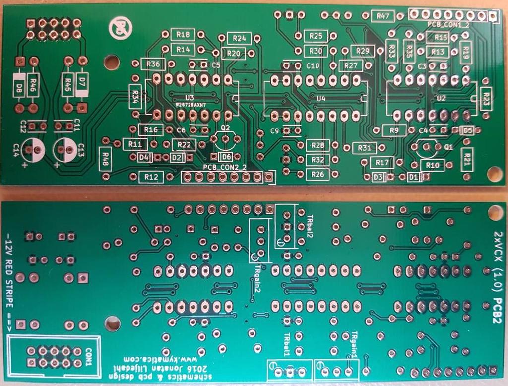
2 PCB pictures PCB PCB


3 Assembly instructions We start with PCB. Step Solder small signal diodes. Diodes are sensitive to mounting direction, make sure the stripe on the diode match the stripe on the silkscreen. D, D, D3, D4, D5, D6 N448 6pcs Step Solder resistors. Resistors are not sensitive to mounting direction. R0, R, R6, R7, R9, R0 00K 6pcs R, R, R9, R3, R47, R48 0K 6pcs


4 R3, R4, R7, R8 K 4pcs R5, R6, R30, R3 470R 4pcs R45, R46 0R pcs


5 R9, R, R3, R4, R5, R8, R33, R34, R35, R36 00k 0pcs Step 3 Solder power polarity protection diodes. Diodes are sensitive to mounting direction, make sure the stripe on the diode match the stripe on the silkscreen. D7, D8 N588 pcs Step 4 Solder ceramic capacitors. Ceramic capacitors are not sensitive to mounting direction. C3, C4, C5, C6, C9, C0, C, C 00nF 8pcs

 pcs Step 6 Solder electrolytic capacitors.")
 on the silkscreen.")
6 Step 5 Solder IC sockets. Match the IC sockets indent (marking pin side) with the silk screens. If you feel the least uncertain on the IC direction, please search the web for IC orientation. U, U3 4 pin DIP sockets (DIP-4) IC's will be mounted later. pcs U4 6 pin DIP socket (DIP-6) pcs Step 6 Solder electrolytic capacitors. Electrolytic capacitors are sensitive to mounting direction. Put the long pin in the hole marked with a + (anode) on the silkscreen. The opposite side - (cathode) is marked with fully filled silkscreen. C3, C4 0µF pcs Step 7 Solder transistors, transistors are sensitive to mounting direction. Match the curved side on the transistor with the curved side in the silkscreen. Q, Q BC557B pcs


7 Step 8 Flip PCB to the bottom side. Solder the power header. Make sure the key opening is oriented in the same way as in the picture below. It's easier to avoid bent pins if you attach the power cable in the header while you are soldering. CON x5pin Step 9 Flip PCB to the bottom side. Now it's time to solder trimmers. They are not sensitive to mounting direction. TRbal, TRbal 50R multi turn trimmer pcs TRgain, TRgain 50k multi turn trimmer pcs


8 Step 0 Insert the ICs in the sockets. If you feel the least uncertain on the IC direction, please search the web for IC orientation. U, U3 TL074/TL084 pcs U4 LM3700 pcs Leave PCB on the side with the PCB to PCB connectors not soldered. Now it's time for PCB. Step Solder resistors. Resistors are not sensitive to mounting direction. R, R, R3, R4, R5, R6, R7, R8, R37, R38, R39, R40, R4 00k 3pcs R4, R43, R44 k 3pcs

 with the silk")

9 Step Solder ceramic capacitors. Ceramic capacitors are not sensitive to mounting direction. C, C, C7, C8 00nF 4pcs Step 3 Solder IC sockets and insert IC's. Match the IC sockets indent (marking pin side) with the silk screens. If you feel the least uncertain on the IC direction, please search the web for IC orientation. U 4 pin DIP socket (DIP-4) U5 8 pin DIP socket (DIP-8) U TL074/TL084 U5 TL07/TL08


10 Step 4 Mount the spacers with the nuts on PCB. You can have the screw-side on PCB as well if you feel that it's more comfortable. Step 5 Put the pin & socket strips into each other. Place them between PCB and PCB in their respective places. Take a firm grip with a plier around the spacers and screw the screws into place. If the nuts gets loose, tighten them again. Remove them again after the pin & socket strips are soldered. Solder the connectors.


11 Step 6 Cut off the small metal tab sticking out on the potentiometers. Use a cheap plier/nipper for this step, save your expensive ones for other tasks. Mount washer and nut on each potentiometer. Make sure the nuts are tight. Sometimes we ship the kits with Alpha potentiometers and they are cleasly marked with "Alpha". In that case you don't need any washer or nut under the panel. Step 7 Place potentiometers, jacks and switches in their positions but wait with soldering until the front panel is mounted. You will need to bend the ground pins a little bit on the jacks.


12 Step 8 Place the front panel on top and add washer and nut to each potentiometer and jack, nut to the switches. Use a socket wrench to avoid scratching of the frontplate. The switches have big pad holes to allow more different switches to fit but it also means you need to be extra careful to make sure the switch is aligned straight. The switches have their own nuts, Make sure to keep them separate from the jacks nuts as they look very similar and the switch nuts will fit on the jacks but the jack nuts won't fit on the switches. Now you solder all panel components in place. Step 9 Now attach PCB to the module and screw the spacers together like in step 4-5. Remember the firm grip with the pliers. Mount the knobs. Now attach the power cable with the stripe indicating pin on the -V side.
 Set the toggle at the right (B>A) position, turn OFFSET knob to 0% and CV attenuator knob to 00% +. 3) Patch VCO to CV input and adjust TRbal for minimum CV feed-through on OUT.")
13 Cablibration For best result, let the module warm up with power on for 0-30 minutes before calibration. Use either your hearing or an oscilloscope. ) Patch an unconnected cable to the A input. ) Set the toggle at the right (B>A) position, turn OFFSET knob to 0% and CV attenuator knob to 00% +. 3) Patch VCO to CV input and adjust TRbal for minimum CV feed-through on OUT. 4) Move VCO patch cable to B input, turn OFFSET knob to 00% and adjust TRgain for minimal amplitude on OUT. 5) Repeat until satisfaction. Do the same for the second channel (). Finished module!
Ljunggren Audio Roll Your Own Penta
 Ljunggren Audio Roll Your Own Penta Version: Penta 1.0 Bills Of Material Bold = PCB1, The rest = PCB2 Type Parts Des cription Pow er header Qty Value 1 2x5pin POWER Euro pow er connector Jack 1 3.5mm J1,
D6, D7, D8, D9, D12, D13, D14, D15, D16, D17, D18, D19. Schottky rectifier diode. 1N5817-1N5819 or SB130
 Roll Your Own ljunggrenaudio.com Altered States version 1.0 Bills Of Material Qty Value 12 1N4148 2 1N5818 4 1N750 4.7V 4 220p Device Diode Diode Zener diode Capacitor 30 100n 4 15p 8 560p 1 5x2 pin Capacitor
Ljunggren Audio Roll Your Own Optodist
 Ljunggren Audio Roll Your Own Optodist Version: Optodist/VCA.0 Bill Of Material TYPE PART VALUE PCS NOTE Resistor R,R 0R Resistor R5,R0 K Resistor R3,R4 0K Resistor R,R9 68K Resistor R 00K Resistor R3
SERGE Dual Universal Slope Generator (DSG) mk2 for Eurorack
 mk2 for Eurorack") SERGE Dual Universal Slope Generator (DSG) mk2 for Eurorack The Serge Dual Universal Slope Generator DSG is one of the most versatile modules in the Serge system. The DSG mk2 by Random*Source is a licensed
SERGE Dual Universal Slope Generator (DSG) mk2 for Eurorack The Serge Dual Universal Slope Generator DSG is one of the most versatile modules in the Serge system. The DSG mk2 by Random*Source is a licensed
MOTHMAN FUZZ ASSEMBLY INSTRUCTIONS RECOMMENDED TOOL AND SUPPLY LIST MOTHMAN FUZZ KIT PARTS LIST
 MOTHMAN FUZZ ASSEMBLY INSTRUCTIONS Thank you for purchasing the J201 Clean Boost Pedal Kit from Mammoth Electronics! This is a intermediate level kit that and we have made every effort to make the assembly
DECIDUOUS FILTER ASSEMBLY INSTRUCTIONS RECOMMENDED TOOL AND SUPPLY LIST DECIDUOUS FILTER KIT PARTS LIST
 DECIDUOUS FILTER ASSEMBLY INSTRUCTIONS Thank you for purchasing the Deciduous Filter Effect Pedal Kit from Mammoth Electronics! This is an intermediate level kit and we have made every effort to make the
IDC-136II-KIT 136kHz DC RX Assembly Guide
 IDC-136II-KIT 136kHz DC RX Assembly Guide ICAS Enterprises May 2 nd,2016 The IDC-136II-KIT is a 136kHz direct conversion receiver. Most of the SDR software can be used with this receiver. It is quite easy
CAPI BB2521 Build Guide & BOM
 This is a very simple build. I only have a few tips and things to look out for. I do recommend following these steps due to the diode/transistor relationship. 1. Install the three ceramic caps. If you
SERGE Variable Resonance Filter (VCFQ)
") SERGE Variable Resonance Filter (VCFQ) The Random*Source version of the filter is an updated design that uses 3 high-end THAT280 VCAs for superior audio performance - a change that has been approved by
SERGE Variable Resonance Filter (VCFQ) The Random*Source version of the filter is an updated design that uses 3 high-end THAT280 VCAs for superior audio performance - a change that has been approved by
White Light CLASSIC PEDAL KIT. Assembly Instructions WHEN YOU CAN T BUY IT BUILD IT. StewMac RARE / VINTAGE / HARD TO GET
 Sheet #i-2206 Updated 5/18 StewMac White Light CLASSIC PEDAL KIT Kit case is unpainted IN COLLABORATION WITH EarthQuakerDevices Assembly Instructions The White Light Overdrive is based on vintage overdrives
Assembly Instructions for the KA Electronics Flat MM Phono Preamplifier
 Assembly Instructions for the KA Electronics Flat MM Phono Preamplifier Install IC sockets Flat MM Phono Preamp PC Board Stuffing Guide Place the PC Board on the bench silkscreen side face up. Drop six
Chapter 2. Battery Charger and Base Assembly
 Chapter 2 Battery Charger and Base Assembly 11 CHAPTER 2. BATTERY CHARGER AND BASE ASSEMBLY 2.1 Section Overview This Lab teaches students how to assemble a Tekbot, in the following steps: Describe the
Assembly and User Guide
 Assembly and User Guide 2 Amp Adjustable Electronic Load 30V and 20 Watts Max Powered by: 9V Battery Pico Load is a convenient constant current load for testing batteries and power supplies. The digital
Arlo Power Distribution Board Kit (#28996)
") Web Site: www.parallax.com Forums: forums.parallax.com Sales: sales@parallax.com Technical: support@parallax.com Office: (916) 624-8333 Fax: (916) 624-8003 Sales: (888) 512-1024 Tech Support: (888) 997-8267
Web Site: www.parallax.com Forums: forums.parallax.com Sales: sales@parallax.com Technical: support@parallax.com Office: (916) 624-8333 Fax: (916) 624-8003 Sales: (888) 512-1024 Tech Support: (888) 997-8267
Tri Boost Kit Instructions
 Tri Boost Kit Instructions Click here for older triboost version instructions(no 3-way LED) Parts Checklist...page 2-3 Schematic.....page 4 Populating and mounting the circuit board..page 5-14 Wiring Diagram.......page
k" or #8 nut driver A pair of regular pliers can substitute for the nut drivers but will
 Page of 3 ARIES SYSTEM 300 MUSIC SYNTHESIZER Module AR-38 STEREO REVERB & OUTPUT ASSEMBLY INSTRUCTIONS The previous pages were written as a general guide to familiarize the builder with the components.
Arlo Power Distribution Board Kit Rev B (#28996)
") Web Site: www.parallax.com Forums: forums.parallax.com Sales: sales@parallax.com Technical: support@parallax.com Office: (916) 624-8333 Fax: (916) 624-8003 Sales: (888) 512-1024 Tech Support: (888) 997-8267
Web Site: www.parallax.com Forums: forums.parallax.com Sales: sales@parallax.com Technical: support@parallax.com Office: (916) 624-8333 Fax: (916) 624-8003 Sales: (888) 512-1024 Tech Support: (888) 997-8267
mb808 FAB manual
 mb808 FAB manual http://www.eight-oh-eight.org Step one: Power Supply: ATTENTION: You will be dealing with AC mains voltages in this part of the build, if you are not careful you can injure yourself, or
ez1081pre Mic Amplifier - Assembly manual [ Colourbook Issue 1]
![ez1081pre Mic Amplifier - Assembly manual [ Colourbook Issue 1]](/thumbs/90/103906919.jpg "ez1081pre Mic Amplifier - Assembly manual [ Colourbook Issue 1]") ez1081pre Mic Amplifier - Assembly manual [ Colourbook Issue 1] ez1081pre Colourbook Contents. Section 1 - Colourbook assembly guide Section 2 - Setup and Calibration Section 3 - Schematics diagrams and
ez1081pre Mic Amplifier - Assembly manual [ Colourbook Issue 1] ez1081pre Colourbook Contents. Section 1 - Colourbook assembly guide Section 2 - Setup and Calibration Section 3 - Schematics diagrams and
Build Instructions and User Guide
 Build Instructions and User Guide Getting Started To build the Rock Drill 4069 you will need: Solder Wire Cutters Soldering Iron Small pliers The kit is suitable for beginners or more experienced builders
IV-11 VFD tube clock Assembly instructions v1.2.2
 IV-11 VFD tube clock Assembly instructions v1.2.2 Designer: Website: E-mail: Yan Zeyuan. China http://www.nixieclock.org yanzeyuan@qq.com 2017-01-26 NCH Attention Attention: Warning: Warning: Warning:
IV-3 VFD Shield for Arduino. Assembly Manual
 June 2014 Table of Contents 1 Overview Features Applications 3 3 3 2 Assembly Hints 4 3 PCB Overview 5 4 Circuit Diagram 6 5 Assembly Diodes and IC socket Electrolytic capacitors Ceramic capacitors 10K
Norcal Power/SWR Meter Assembly & Operating Manual. Revision 1D 10/15/2008
 Norcal Power/SWR Meter Assembly & Operating Manual Revision 1D 10/15/2008 Copyright 2008 NorCal QRP Club Page 1 of 21 Contents CONTENTS...2 INTRODUCTION...3 SPECIFICATIONS...3 ASSEMBLY...4 OPERATING GUIDE...15
MonoWave(X) Construction Guide Version 1.2. June 30th, 2018
 Construction Guide Version 1.2. June 30th, 2018") MonoWave(X) Construction Guide Version 1.2 June 30th, 2018 1 of 10 Construction Construction of the MonoWave (X) is relatively straightforward and generally only requires good general soldering skills.
MonoWave(X) Construction Guide Version 1.2 June 30th, 2018 1 of 10 Construction Construction of the MonoWave (X) is relatively straightforward and generally only requires good general soldering skills.
Soldering Pi2Go Lite. Soldering the Line-Follower PCB
 Soldering Pi2Go Lite First check which version of the main PCB you have. It is marked above the left motor "Pi2Go-Lite v1.x". There are minor changes to some parts of the build. v1.0 (initial release)
Arlo Power Distribution Board Kit Rev B (#28996)
") Web Site: www.parallax.com Forums: forums.parallax.com Sales: sales@parallax.com Technical: support@parallax.com Office: (916) 624-8333 Fax: (916) 624-8003 Sales: (888) 512-1024 Tech Support: (888) 997-8267
Web Site: www.parallax.com Forums: forums.parallax.com Sales: sales@parallax.com Technical: support@parallax.com Office: (916) 624-8333 Fax: (916) 624-8003 Sales: (888) 512-1024 Tech Support: (888) 997-8267
EQ73 Parts list Reference Value Qty Description Marking Dim Manuf. YEL-VIO-BLK-GLD-BRN RED-RED-BRN-BRN RED-RED-BLK-BLK-BRN GRN-BLU-BRN-BRN
 EQ73 Parts list (1) Reference Value Qty Description Marking Dim (2) Manuf. R52, R53 47R 2 Resistor 1%, 1/4W YEL-VIO-BLK-GLD-BRN R45, R46 180R 2 Resistor 5%, 1/2W R23, R24 220R 2 Resistor 1%, 1/4W RED-RED-BRN-BRN
What is the E340? Connecting to the power supply
 PAGE 1 E340 Cloud Generator DIY Kit www.synthtech.com/euro/e340 What is the E340? The Synthesis Technology E340 is a dual output VCO that contains 8 oscillators. These oscillators can be detuned by a control
Maglev Plus System. 1. Description
 1. Description Maglev Plus System The Maglev Plus System is specifically designed to levitate various objects attached to a very strong disc magnet. It can levitate up to 25 g additional mass. The vertical
CLASSIC PEDAL KIT. Assembly Instructions WHEN YOU CAN T BUY IT BUILD IT. StewMac Monarch RARE / VINTAGE / HARD TO GET
 Sheet #i-2205 Updated 2/8 StewMac Monarch CLASSIC PEDAL KIT Kit case is unpainted IN COLLABORATION WITH EarthQuakerDevices Assembly Instructions The Monarch Overdrive is an all discrete, FET-based dirt
BUMP AND SPIN KIT ESSENTIAL INFORMATION. Version 1.0 PROGRAM AND DESIGN YOUR OWN BUGGY WITH THIS
 ESSENTIAL INFORMATION BUILD INSTRUCTIONS CHECKING YOUR PCB & FAULT-FINDING MECHANICAL DETAILS HOW THE KIT WORKS PROGRAM AND DESIGN YOUR OWN BUGGY WITH THIS BUMP AND SPIN KIT Version 1.0 Build Instructions
synthcube 291 VCF (buchla / verbos circuit realized by dustin stroh) module documents v2.0 06/20/2014 PCB rev 2.0 Errata:
 module documents v2.0 06/20/2014 PCB rev 2.0 Errata:") synthcube 291 VCF (buchla / verbos circuit realized by dustin stroh) module documents v2.0 06/20/2014 PCB rev 2.0 Errata: copyright 2012 synthcube.com Page 1 Circuit Description A discussion thread about
synthcube 291 VCF (buchla / verbos circuit realized by dustin stroh) module documents v2.0 06/20/2014 PCB rev 2.0 Errata: copyright 2012 synthcube.com Page 1 Circuit Description A discussion thread about
SCA-80(Q) C11 REPLACEMENT ASSEMBLY MANUAL
 C11 REPLACEMENT ASSEMBLY MANUAL") SCA-80(Q) C11 REPLACEMENT ASSEMBLY MANUAL 2014-2016 AkitikA, LLC All rights reserved Revision 1p05 July 3, 2016 Page 1 of 15 Table of Contents Table of Contents... 2 Table of Figures... 2 Section 1: About
SCA-80(Q) C11 REPLACEMENT ASSEMBLY MANUAL 2014-2016 AkitikA, LLC All rights reserved Revision 1p05 July 3, 2016 Page 1 of 15 Table of Contents Table of Contents... 2 Table of Figures... 2 Section 1: About
Simple Eurorack Row. Kit Builder's Guide. 4mspedals.com
 Simple Eurorack Row Kit Builder's Guide 4mspedals.com ' Simple Eurorack Row This guide is for building a single-row eurorack case with a power supply. When completed, the case is ready to accept eurorack
The ability to make basic voltage and resistance measurements using a digital multimeter
 Seventh Circle Audio C84 Microphone Preamp Based on the innovative Double Balanced Microphone Amplifier circuit published by Graham John Cohen in 1984, the C84 microphone preamp offers exceptional performance
DIY Synth Kit - Manual STUTTER SYNTH
 DIY Synth Kit - Manual STUTTER SYNTH Welcome to the DIY Synth - Manual This is a step-by-step guide to making your own electronic Synth. All you will need is your hands and your DIY Synth kit which includes
ASSEMBLY INSTRUCTIONS FOR NEW FK109 4 LED Railroad Crossing Flasher Kit WITH ADJUSTABLE FLASHING SPEED CONTROL with 4 Red 3mm Leds
 ASSEMBLY INSTRUCTIONS FOR NEW FK109 4 LED Railroad Crossing Flasher Kit WITH ADJUSTABLE FLASHING SPEED CONTROL with 4 Red 3mm Leds Description: Very easy to build, The FK109 Led Flasher kit makes the perfect
22K (red red orange gold) 1pcs. 33K (orange orange orange gold) 5pc. 2.7 M (green violet red gold) 2pc.
 1pcs. 33K (orange orange orange gold) 5pc. 2.7 M (green violet red gold) 2pc.") TURNING FROG Long pliers, soldering, soldering iron stand with sponge, 2 AA batteries, one 9V battery, Tin, diagonal cutting pliers Turning Frog is a robot that uses a microphone as a detector. When microphone
TURNING FROG Long pliers, soldering, soldering iron stand with sponge, 2 AA batteries, one 9V battery, Tin, diagonal cutting pliers Turning Frog is a robot that uses a microphone as a detector. When microphone
0-28 vdc stabilized power supply with current control Amp
 0-28 vdc stabilized power supply with current control 0.002-10 Amp General Description This is a high quality power supply with a continuously variable stabilised output adjustable at any value between
UK-electronic 2012/15
 UK-electronic 2012/15 Manual for the Kit Zentaurus Rev 1.21 with buffer or True bypass Page 1...Cover Page 2..3...Allocations, basics Page 4...5...Bill of material Page 6...7...Soldering the pcb Page 8...Building
DIY Synth Kit - Manual
 DIY Synth Kit - Manual Welcome to the DIY Synth - Manual This is a step-by-step guide to making your own electronic Synth. All the equipment you ll need to make your synth is your DIY Synth kit and of
QRPGuys Digital RF Probe
 QRPGuys Digital RF Probe First, familiarize yourself with the parts and check for all the components. If a part is missing, please contact us and we will send one. This kit contains seventeen 1206 size
Mableaudio Company limited
 Mableaudio Company limited Web: www.mableaudio.com [5E3 assembly manual] Tel:0086-755-83996326 fax:0086-755-83996326 Contact: Ms Mable mable@mableaudio.com WARNING! This amp operates at voltages that may
Assembly Manual for ISDR-136-KIT
 Assembly Manual for ISDR-136-KIT ICAS Enterprises Last Updated March 21 st, 2012 This SDR receiver kit is intended for the 136kHz band. The kit utilizes DIP IC components (no SMD) so that even a beginner
Collosalus 2015 FX Type: Flanger 3.25 W x 2.9 H
 Collosalus 2015 FX Type: Flanger Based on the MXR 117 Download the previous version documentation here: http://www.madbeanpedals.com/projects/collosalus/collosalus.zip 3.25 W x 2.9 H B.O.M. Resistors Caps
Kit1 300B Edition. Single Ended Triode 8 Watt. Construction Manual & User Guide Volume One
 Kit1 300B 2014 Edition Single Ended Triode 8 Watt Construction Manual & User Guide Volume One Contents Section 1: Receiving your kit...2 Section 2: The Mechanical section Preparation... 3 Tang Strips...
SM361 RIG SWITCH CONSTRUCTION MANUAL
 SM361 RIG SWITCH CONSTRUCTION MANUAL Document ver 1, For software release ver 1.1 May 27, 2016 Controls the power of 12V equipment while a vehicle is in use Product Development by: SM361 RIG SWITCH OVERVIEW
~Dashboard Digital Voltmeter~
 ~Dashboard Digital Voltmeter~...November, 2002 This project is helpful to anyone who drives an automobile. I had found this project at the local libary... in an old publication. I made it and it worked
Electronic Dice Kit MitchElectronics 2019
 Electronic Dice Kit MitchElectronics 2019 www.mitchelectronics.co.uk CONTENTS Schematic 3 How It Works 4 Materials 5 Construction 6 Important Information 7 Page 2 SCHEMATIC Page 3 SCHEMATIC EXPLANATION
PSL2 Assembly guide. PSL2 Assembly guide. Resistors. Test pins. Document revision 1.1 Last modification : 30/05/08
 Safety warning THIS KIT IS NOT FOR BEGINNERS! This kit is main powered and use potentially lethal voltages. Under no circumstance should someone undertake the realisation of this kit unless he has full
Parts List DIY-81 rev 1. Capacitors. DIY-81 Project Parts list rev 1
 Electrolytic C100 100 25 Axial 8 x 100uF/25V Axial C101 150 16 Axial 8 x 150uF/16V Axial C102 150 16 Axial 2 x 470uF/16V Radial C18 470 16 Radial C103 150 16 Axial C104 150 16 Axial C106 100 25 Axial C105
QUASAR ELECTRONICS KIT No WINDSCREEN WIPER CONTROLLER
 QUASAR ELECTRONICS KIT No. 1093 WINDSCREEN WIPER CONTROLLER General Description This is a very useful accessory for any car. It can adjust the frequency of operation of the windscreen wipers between once
HW-8-LM386 Audio Amplifier Board Assembly Instructions
 This LM386 based audio amplifier kit was designed to replace the small audio amplifier board in the Heathkit HW-8 transciever. The result is the ability to drive regular modern day 8 ohm headphones or
100W SUBWOOFER KIT. Total solder points: 383 Difficulty level: beginner advanced K8077 ILLUSTRATED ASSEMBLY MANUAL
 100W SUBWOOFER KIT Powerful bass from a small cabinet thanks to the dual speaker principle Total solder points: 383 Difficulty level: beginner 1 2 3 4 5 advanced K8077 ILLUSTRATED ASSEMBLY MANUAL H8077IP-1
IR Gun Assembly Instructions
 IR Gun Assembly Instructions Rev 1.01 SenselessDevices.com 1 Description The IR Gun is part of a shooting Arcade project. Together with the target kits, a variety of shooting galleries can be constructed.
PM-200 POWER SUPPLY MODULE v3.2 ASSEMBLY & INSTALLATION INSTRUCTIONS
 PM-200 POWER SUPPLY MODULE v3.2 ASSEMBLY & INSTALLATION INSTRUCTIONS WARNING: Voltages inside the amplifier CAN & WILL KILL YOU! You MUST know how to work around HIGH VOLTAGE safely. If you do not, get
POWER AMPLIFIER SERVICE MANUAL CONTENTS
 POWER AMPLIFIER CONTENTS Performance Specifications... 2 Notes... 2 Rear Panel... 3 Section Location... 3 Block Diagram... 4 Interconnection Diagram... 5-8 Multi-channel Schematic and PCB... 9 Heatsink
The ability to make basic voltage and resistance measurements using a digital multimeter
 Seventh Circle Audio N72 Microphone Preamp Based on the BA183 amplifier circuit used in the 1066, 1073, 1272, and other Neve console modules, the N72 microphone preamp will deliver the same immediately
openqrp Transceiver Parts List By Functional Section 1/11/2014 Using openqrp PC Board Rev D, 40M Version
 openqrp Transceiver Parts List By Functional Section 1/11/2014 Using openqrp PC Board Rev D, 40M Version Section 1 AGND Schematic Page 2 R37 [I8] 10K 1/8W Resistor (Brown Black Orange) R38 [J9] C80 [J9]
JHS 808. CLASSIC PEDAL KIT Assembly Instructions. StewMac
 heet #i-2150 Updated 12/17 tewmac JH 808 CLAIC PEDAL KI Assembly Instructions he JH808 is one of the great stompboxes from JH, makers of high-end effects pedals. Whenever JH adds a new pedal to their line,
Virtual Ground for HV Boosters Calibration
 Dear all utracer users, I m writing these lines just to share my experience building my utracer, so that maybe someone could find it useful for his design. The construction of my utracer was very simple,
CTB-16K Hobbyist Line Kit 40 Amp 16 Channel Light Controller Assembly Manual *** Preliminary ***
 CTB-16K Hobbyist Line Kit 40 Amp 16 Channel Light Controller Assembly Manual *** Preliminary *** Version 1.0 January 12, 2006 Copyright Light O Rama, Inc. 2006 Table of Contents 1 Introduction... 3 2 Required
Total solder points: 187 Difficulty level: beginner advanced. Code lock K6400 ILLUSTRATED ASSEMBLY MANUAL
 Total solder points: 187 Difficulty level: beginner 1 2 3 4 5 advanced Code lock K6400 Ged rid of those old fashioned keys ILLUSTRATED ASSEMBLY MANUAL H6400IP-2 Features & Specifications Features: More
SS & SS SOFT-START v3.0 ASSEMBLY & INSTALLATION INSTRUCTIONS
 SS-221-120 & SS-221-240 SOFT-START v3.0 ASSEMBLY & INSTALLATION INSTRUCTIONS WARNING: Voltages inside the amplifier CAN & WILL KILL YOU! You MUST know how to work around HIGH VOLTAGE safely. If you do
WIRING THE HEATER POWER SUPPLY
 WIRING THE HEATER POWER SUPPLY Fig. 14 13/14 Take the longer PS board (with the 47R resistors and the fuse) and, using M3x6 screws, fix it to the chassis to the left of the mains transformer. The diodes
Linear Stepper Driver v0.9.2 Assembly Instructions
 Linear Stepper Driver v0.9.2 Assembly Instructions Here's what's included in the kit: 1x Printed Circuit board 1x Heatsink bracket 5x 0.1uF capacitors 1x 6-pin ISP header 1x 10-pin configuration header
QUASAR ELECTRONICS KIT No ELECTRONIC CAR IGNITION
 QUASAR ELECTRONICS KIT No. 1058 ELECTRONIC CAR IGNITION General Description The advantages of having an electronic ignition in your car are well known. Let us mention them again: 1. Perfect burning of
WHDTS Smart Car Kit D2-5 Electric Soldering DIY Kits
 D2-5 Smart Car Kit Intructions Foreword Thank you for choosing the D2-5 smart car kit. This kit gives you an initial understanding of the principles and techniques of automatic control. We hope you can
RGB Alarm Clock. -Color Alarm Clock-
 RGB Alarm Clock -Color Alarm Clock- Table of Contents Preamble:...2 List of parts...3 Components...5 Parts and belongings...5 Clock Board Assembly...8 Identification of SMD parts:...0 The power supply
Disaster Transport CLASSIC PEDAL KIT. Assembly Instructions WHEN YOU CAN T BUY IT BUILD IT. StewMac RARE / VINTAGE / HARD TO GET
 StewMac Sheet #i-2203 Updated 5/8 Disaster Transport CLASSIC PEDAL KIT Kit case is unpainted IN COLLABORATION WITH EarthQuakerDevices Assembly Instructions The Disaster Transport is an analog voiced digital
FiveFish Studios PSU-2448Plus+ Assembly Guide
 FiveFish Studios PSU-2448Plus+ Assembly Guide Copyright 2015-2017 FiveFish Audio Revision 1.02-20171105 No part of this document may be reproduced, either mechanically or electronically, posted online
Hasse Mods for the Ampeg J20 Guitar Amp
 Hasse Mods for the Ampeg J20 Guitar Amp The following is adapted from a post I put up on The Gear Page, in the Amp Techincal forum. It shows the mods I did to my Ampeg J20. Okay, here s my mods for this
ALL AMERICAN. CLASSIC PEDAL KIT Assembly Instructions. StewMac
 heet #i-2153 Updated 12/17 tewmac ALL AMERICAN CLAIC PEDAL KI Assembly Instructions he ALL-AMERICAN is one of the great stompboxes from JH, makers of high-end effects pedals. Whenever JH adds a new pedal
IMPORTANT WARRANTY INFORMATION! PLEASE READ
 IMPORTANT WARRANTY INFORMATION! PLEASE READ Return Policy on Kits When Not Purchased Directly From Vectronics: Before continuing any further with your VEC kit check with your Dealer about their return
K3500 MULTIFUNCTION CAR COURTESY LIGHT. Specifications
 Total solder points: 87 Difficulty level: beginner 1 2 3 4 5 advanced MULTIFUNCTION CAR COURTESY LIGHT K3500 Never look for the ignition switch in the dark again. Specifications switch-off delay: adjustable
Tip: LED Lighting Improvements for Rheingold Set Date:
 Hi All, Recently I came into possession of the 41928 Rheingold set and was excited to see that I could add a function decoder to switch the light functions on and off. The first problem is Märklin don
PR-101 STEREO PREAMPLIFIER ASSEMBLY MANUAL
 PR-101 STEREO PREAMPLIFIER ASSEMBLY MANUAL 2015-2018 AkitikA LLC All rights reserved Revision 5p09 March 8, 2018 Page 1 of 68 Table of Contents Table of Contents... 2 Table of Figures... 4 Section 1: About
General Purpose Flasher Circuit
 General Purpose Flasher Circuit By David King Background Flashing lights can be found in many locations in our neighbourhoods, from the flashing red light over a stop sign, a yellow warning light located
Q182-RP20 Ribbon Controller
 The RP20 is a position and pressure-sensitive ribbon controller capable of replacing or augmenting a traditional keyboard in an analog synthesizer system. The RP20 can be held like a guitar, played from
MOD 102+ GUITAR AMP KIT (K-MOD102+)
") MOD 102+ GUITAR AMP KIT (K-MOD102+) ON BASS 4 6 TREBLE 4 6 VOLUME 4 6 7 7 7 STBY OFF STBY 2 8 MOD 102+ TUBE AMP KIT 1 9 modkitsdiy.com 0 10 Pull-MID BOOST 2 8 1 9 0 10 Pull-BRIGHT 2 8 1 9 0 10 Pull-TURBO
MOD 102+ GUITAR AMP KIT (K-MOD102+) ON BASS 4 6 TREBLE 4 6 VOLUME 4 6 7 7 7 STBY OFF STBY 2 8 MOD 102+ TUBE AMP KIT 1 9 modkitsdiy.com 0 10 Pull-MID BOOST 2 8 1 9 0 10 Pull-BRIGHT 2 8 1 9 0 10 Pull-TURBO
THE PERSUADER DELUXE (K-980)
") THE PERSUADER DELUXE (K-0) BOOST VOLUME GAIN Unplug when not in use to save battery life. TO AMP IN The Persuader Deluxe Tube Drive modkitsdiy.com FROM GUITAR OUT LED VDC CENTER (-) ADAPTER Use these instructions
THE PERSUADER DELUXE (K-0) BOOST VOLUME GAIN Unplug when not in use to save battery life. TO AMP IN The Persuader Deluxe Tube Drive modkitsdiy.com FROM GUITAR OUT LED VDC CENTER (-) ADAPTER Use these instructions
ECO-6 & Installation Manual
 ECO-6 & Installation Manual For the SPA4-RFR Upgrade Kit To upgrade SPA4 amplifiers v1.00 & v1.01 to v2.0 Some sections also apply to the PA1, PA2, and PA3 14 August 2015 2015 by Ralph Hartwell Spectrotek
Schematic VCC J1 1 CON1 +5V D26 D25 D7 D8 D9 D10 D11 D12 D19 D20 D21 D22 D23 D24 D1 D2 D3 D4 D5 D6 D13 D14 D15 D16 D17 D18 R4 100R R2 100R R6 100R
 Schematic +5V S D1 D2 D3 D4 D5 D6 D7 D8 D9 D10 D11 D12 D19 D20 D21 D22 D23 D24 D13 D14 D15 D16 D17 D18 D25 D26 R1 4K7 R2 100R Q1 9014-PNP C1 47uF R3 4K7 R4 100R Q2 9014-PNP C2 47uF R5 4K7 R6 100R Q3 9014-PNP
Build a Simple Handheld Throttle for the Digitrax Zephyr
 Build a Simple Handheld Throttle for the Digitrax Zephyr Here is a way to build a simple three button throttle for use with the Digitrax popular Zephyr. This handheld throttle is designed work with the
ACL 780/781 Economy Combo Tester
 ACL 780/781 Economy Combo Tester OPERATION MANUAL Meter is warranted for one year from the date of purchase on parts and labor. Calibration is recommended every twelve months. 840 W. 49 th Place Page 1
FX TYPE: DISTORTION Based on the Suhr Riot PCB artwork m2011 madbeanpedals Special thanks to culturejam! Release date: REVISED
 http://www.madbeanpedals.com presents uproar FX TYPE: DISTORTION Based on the Suhr Riot PCB artwork m2011 madbeanpedals Special thanks to culturejam! Release date: 01.30.11 REVISED 02.08.11 This version
SB-GVS Shield v1.0. ! Ideal for servo & sensor accessories (Phidgets, Seeed Bricks)! Full break-out for all 12 digital lines & 6 analog lines 2
! Full break-out for all 12 digital lines & 6 analog lines 2") SB-GVS Shield v1.0 Arduino tm -Compatible Sensor Interface Connect up 18 peripherals to the popular Ground/Voltage/Signal interface. Got more? Use the IC-interface too! Build Time: 0mins Skill Level: Beginner
SB-GVS Shield v1.0 Arduino tm -Compatible Sensor Interface Connect up 18 peripherals to the popular Ground/Voltage/Signal interface. Got more? Use the IC-interface too! Build Time: 0mins Skill Level: Beginner
HW-8-LM386 Audio Amplifier Board Assembly Instructions
 This LM386 based audio amplifier kit was designed to replace the small audio amplifier board in the Heathkit HW-8 transciever. The result is the ability to drive regular modern day 8 ohm headphones or
Lab Electronics Reference: Tips, Techniques, and Generally Useful Information for the Labs
 ENGR 112 September 16, 14 Lab Electronics Reference: Tips, Techniques, and Generally Useful Information for the Labs This guide contains some useful reference information to help get you started on your
LED PICTURE FRAME KIT
 ESSENTIAL INFORMATION BUILD INSTRUCTIONS CHECKING YOUR PCB & FAULT-FINDING MECHANICAL DETAILS HOW THE KIT WORKS MAKE A DISPLAY OF YOUR MOST TREASURED PHOTOGRAPH WITH THIS LED PICTURE FRAME KIT Version
PowerAmp Design. PowerAmp Design EVAL135 EVALUATION KIT FOR MODELS PAD135/ PAD183. Rev D
 PowerAmp Design EVALUATION KIT FOR MODELS PAD35/ PAD83 EVAL35 Rev D INTRODUCTION The EVAL35 evaluation kit provides a convenient method to become familiar with the operation of the PAD35 or PAD83 Compact
THREE PHASE FAULT ANALYSIS WITH AUTO RESET ON TEMPORARY FAULT AND PERMANENT TRIP OTHERWISE
 THREE PHASE FAULT ANALYSIS WITH AUTO RESET ON TEMPORARY FAULT AND PERMANENT TRIP OTHERWISE ABSTRACT The project is designed to develop an automatic tripping mechanism for the three phase supply system.
MOD 102 GUITAR AMP KIT (K-MOD102)
") MOD 0 GUITAR AMP KIT (K-MOD0) ON BASS TREBLE VOLUME MOD 0 TUBE AMP KIT 0 0 0 0 0 0 OFF Use these instructions to learn: How to build a tube amp. This tube guitar amplifier circuit is based on a classic
MOD 0 GUITAR AMP KIT (K-MOD0) ON BASS TREBLE VOLUME MOD 0 TUBE AMP KIT 0 0 0 0 0 0 OFF Use these instructions to learn: How to build a tube amp. This tube guitar amplifier circuit is based on a classic
Switch Machines Installation & Wiring
 Switch Machines Installation & Wiring Conventional Twin Coil Switch Machines Electrically: In use since developed by Walthers in early 1930 s Long time standard for remote operation Currently: Rix, Atlas,
Quiz Buzzer. Build Instructions. Issue 1.2
 Build Instructions Issue 1.2 Build Instructions Before you put any components in the board or pick up the soldering iron, just take a look at the Printed Circuit Board (PCB). The components go in the side
802C System Controller Original and SMD Version
 802C System Controller Original and SMD Version Units with serial numbers beginning with 100000 are the original 802C's. Units with serial numbers beginning with 200000 are the new SMD 802C's. 1997 Bose
Total solder points: 93 Difficulty level: beginner advanced 10 LED MONO VU METER K4304 ILLUSTRATED ASSEMBLY MANUAL
 Total solder points: 93 Difficulty level: beginner 1 2 3 4 5 advanced 10 LED MONO VU METER K4304 Add a visual readout to your existing or new equipment. ILLUSTRATED ASSEMBLY MANUAL H4304IP-1 Features &
Handyman Motor Capacitor Meter PART NO
 Handyman Motor Capacitor Meter PART NO. 2225174 To test a motor-run capacitor in the field with no capacitance meter at hand, you had to hook up the capacitor through an extension cable to a 120V wall
Australian Technical Production Services
 Australian Technical Production Services Dual Rail Crowbar Copyright notice. These notes, the design, schematics and diagrams are Copyright Richard Freeman, 015 While I am happy for the notes to be printed
ROBOT SOUND REVERSING CAR KIT C-9802
 ROBOT SOUND REVERSING CAR KIT TOOLS you'll need Alimentation 2 batteries 1,5 V AA (not included) You will find fun to learn electronics and mechanics assembling robot by reversing sound. This is a simple