Virtual Ground for HV Boosters Calibration
|
|
|
- Sherilyn Alexander
- 6 years ago
- Views:
Transcription

1 Dear all utracer users, I m writing these lines just to share my experience building my utracer, so that maybe someone could find it useful for his design. The construction of my utracer was very simple, mounting on top of the enclosure, one octal and one noval sockets, along with the nine 4mm banana jacks for the tube connections and six more banana jacks for the utracer and heater connections. However, it has some features in the front panel, that someone could find useful. Features are: 1) Voltage Booster calibration banana jacks with a virtual ground 2) VSupply calibration banana jacks 3) Variable DC auxiliary heater power supply with display readout of actual voltage and current. Also, has 4mm banana Jacks for voltage and current calibration of the display. 4) Toggle switch for the selection between utracer or auxiliary heater power supply So, I thing features 1 and 3, could be worth mentioning extensively here. Virtual Ground for HV Boosters Calibration Once I finished the assembly of the Booster circuits and calibration were ready to be performed, I thought it would be useful to create in my utracer enclosure, a virtual ground point for a direct reading on a DVM of the high voltages selected on the GUI. So, no need to write down the idle voltages present in the C13 or C18 high voltage capacitors and then subtract them from the final reading on the DVM. Remember that the reading on the DVM is the Vidle + VBoosted. This could be achieved easily with a DVM that has the Δ Relative feature, but for those who doesn t have a DVM with this feature, the virtual ground could be a nice thing to add to the system. The figure below shows the voltage reading taken at the C18 capacitor and the voltage difference between C18 and the Vsuppl. Same reading applies to the C13 high voltage capacitor.
, and the red lead to the positive side of the high voltage capacitors C18 or C13")
2 Initially I figured out some ways to achieve that. My first guess was to connect the black probe of the DVM to the Vsuppl, (in my case +19,53V with respect to ground), and the red lead to the positive side of the high voltage capacitors C18 or C13 that are at a potential of +19,17V with respect to ground (or what is the same, between C18 or C13 terminals). Under that conditions, the idle voltage before switch on the boosters on the GUI was -0,360V. It was pretty close to 0 volts and enough to achieve an accurate calibration of the voltage boosters, but I wanted to get as close as possible to the 0 volts at idle. Then, also tried to connect the black probe of the DVM to the Cathode terminal of the utracer getting -0,100V at idle, since the cathode is at potential of +19,27 with respect to ground. It was perfect, but I didn t want to run a wire from the cathode terminal to the front panel, just to avoid extra inductance in the utracer cathode output terminal and keep the wiring simple. So, I thought Could I get a precise 0 idle voltage to achieve an even more accurate calibration, but leaving intact the utracer terminals? The answer was this pretty simple circuit. Crate a virtual ground at +19,17V potential with respect to ground, which is the same voltage present at the positive side of the high voltage booster capacitors C18 and C13 with respect to ground. Difference between the DVM terminals is then 0 Volts, showing just the boosted voltage when they are ON. Easy!! The use of a variable voltage divider as shown in the above diagram, is quite effective to create an offset adjustment, without running wires from the cathode terminal of the utracer. Place the DVM black probe to the new virtual ground and the red probe to the positive side of the C18 or C13 high voltage capacitors, then adjust the trimmer until you get 0 Volts.

.")
3 Measurement should be performed using a very high input impedance DVM 10MΩ and avoid using oscilloscopes or grounded devices, otherwise the virtual ground becomes ground and voltage reading on the grounded instrument will be the +19,17V, which is the voltage present in the high voltage capacitors C18 or C13 with respect to ground. Also, in that case, RV1 Trimmer could be damaged due an excessive dissipation on it. The diagram below, shows the internal connections of the banana jacks to the voltage divider network that creates the virtual ground (Black 4mm Anode and Screen jacks). Let s do a practical example, so we can compare the original procedure and the virtual ground method. The Original Procedure The GUI is set to generate 300V at the Anode Booster, but first let s measure the idle voltage at the C18 capacitor legs.

 Direct measurement, using the virtual")
4 Now, after start the measurement, the capacitor charges up, until reaches the 300V + Vidle, in that case 300V + 19,17V = 319,1V The Virtual Ground Method Connecting the DVM to the front calibration anode terminals, we can read at idle 0V. (If not, adjust the virtual ground trimmer for 0 Volts) Direct measurement, using the virtual ground connection. Subtraction of the idle voltage is not required.


5 For the sake of completeness, here I attach the measurements that show the different voltages above mentioned. This pic shows the voltage of the positive side of the C18 high voltage capacitor with respect to ground. (or between C18 legs) This pic shows the voltage of the Virtual Ground with respect to ground. This pic shows the 0V difference between both points, waiting to read the boosted voltage.


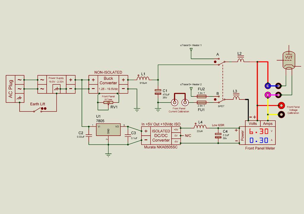
6 Variable DC Auxiliary Heater Power Supply The design of an adjustable auxiliary heater power supply, could be achieved in many different ways. I ve chosen the use of a Buck Converter, that is one of the most efficient ways to get a variable power supply, hence, minimizing the typical heat and space consumption of the linear power supplies. A dedicated 19.5V@2.33A laptop PSU is used to provide the necessary power to the system. The heart of the heater power supply is a module called Buck Converter, that steps down from the input voltage to a minimum voltage of 1.2V, adjusting the output voltage by a trimmer resistor attached to the module. The nice thing about this device is its great efficiency, being around 90-95%. Because of this high efficiency, power at the input of the module, could be almost maintained at the output. Then, as a rough approximation, using the 19.5V@2.33A (45W) laptop PSU as an input source and adjusting the output voltage to 6.30V, the output current that the module could source is roughly 7Amps!! Iout P / Vout -> Iout 45W / 6.30V 7Amps Now, let s do an arbitrary measurement to check the efficiency of the module. As a voltage source, a precision lab PSU set to 20V is used. The output then is set to 10V and connected to a 3.4ohm power resistor. The measured input power to the module was 31.2W and the measured output power was 29.33W. Then, in this case, the efficiency of the module is: η = ( Wout / Win ) x 100 -> η = ( / 31.2 ) x 100 = 94% After 10 minutes of operation, the power resistor that is rated at 50W was pretty hot to the touch, but the module heatsinks were just cold. Conclusion is clear, less heat is generated inside the utracer enclosure.


7 The Buck Converter used in this project could be found on Ebay for about 3, having the following performance specifications Input voltage: 7-40V Output voltage: V Maximum Output Current: 9A Maximum Power: 280W Frequency: 180KHZ As could be seen in the pictures above, the module has an input and output screw connectors as well as the trimmer resistor to adjust the output voltage. In this project, the trimmer resistor has been replaced by a Bourns 10 turn 10KΩ potentiometer ( 3590S-2-103L ) that is attached to the front panel. The use of a single turn potentiometer makes the adjustment very tricky, so 10 turns type is perfect for that purpose. In this picture could be seen the way I attached the potentiometer to the Buck Converter, using a Molex three pin header connector for a quick connection to the module. (Ignore the left trimmer potentiometer seen on the picture. This module has a current limiter feature, but I do recommend the use of the non-current limiter capability version)


8 Voltage and Current Digital Meter For an actual voltage and current measurement of the heater supply, a cheap digital panel meter is used. Despite of the cheapness, using the voltage and current internal trimmers, a very accurate adjustment could be achieved for a precise voltage and current readout. The pictures above, show the meter I used in the project. Many different meters with the same look could be found on Ebay, but I highly recommend to purchase this exact model. I ordered this one and other two similar displays. This one resulted in a very good performance and accuracy, but other two were not very linear, so they were just useless. In order to identify the correct one, search on Ebay a display meter so you can see a picture of the PCB where the connectors and calibration trimmers are located. You should find the following logo (Right picture) printed on it. Also try to include in the search the reference 0-100V 10A TE192. The performance specifications are: Display: 0.28" LED digital Display color: Red (dual display) Operating voltage: DC 4.5 ~ 30V Measure voltage: DC 0 ~ 100V Minimum resolution (V): 0.1V Refresh rate: 500ms / times Measure accuracy: 1% (± 1 digit) Minimum resolution (A): 0.01A Operating Current: <20mA Measure current: 10A (direct measurement, built-in shunt) Operating temperature: -10 to 65 c Operating Humidity: 10 to 80% (non-condensing) Mounting cutout: 45.5 x 26.5mm Dimensions: 48 x 29 x 21mm


9 When we think about how to connect a voltmeter and an ammeter, connections are really straightforward. Voltmeter is connected in parallel and ammeter is connected is series, this results in 4 wires for our connections. Unfortunately, the voltage and current meters existing in this device are not isolated from each other, the ammeter forms part of the negative output of the panel meter, forming a common ground configuration between the two meters. Since the ammeter is linked internally to the voltmeter, this results in 3 wires for the voltmeter and ammeter connections, three thick Black, Red and Yellow wires and two thin black and red wires for the supply of the panel meter itself. The following diagram shows the way the panel is connected to the voltage source and the load. The ammeter is linked to de voltmeter in the low side of the circuit. Notice that in the above diagram, two power supplies are connected to the meter. First one is the voltage source for our heater supply circuit and the second one is the supply for the panel meter itself. It doesn t mean that we need to use two power supplies to run our panel meter, we can use a single power supply with no issues, but, some considerations must be taken into account to make our panel meter to operate correctly and accurately. When I received the panel meter and started to play with it, I rapidly realised that the readings displayed on it were not really accurate, so I decided to adjust the calibration trimmers located on the rear side of the meter. Some minutes after, I saw that the readings were not lineal, at low currents readings were ok, but at high currents they were not. Clearly, I was doing something wrong. After some online research, I found what the problem was. I was connecting the two red and black thin wires to the voltage source, but for some reason, the black wire shouldn t be connected. Another solution for this problem, could be the use of a dc/dc isolated converter just for the panel meter supply. It isolates the ground connection for the panel supply, avoiding the error on the readings.

, would be the main switch On indicator. But, a problem came across when the circuit was tested.")
10 The next diagrams show graphically what is explained above. The dc/dc converter is not included to keep the diagram simple. In my case, I decided to use the dc/dc method for the power supply of the meter. When I designed the features on the front panel, a power on LED was not included in the final design, so was clear that I needed some indication to show the system was switched On. Then, I decided that the meter (switched On), would be the main switch On indicator. But, a problem came across when the circuit was tested. When the heater source was switched to the internal heater of the utracer, the panel meter switched Off. The utracer and the auxiliary heater supply, use two separated laptop power supplies, then, when the internal utracer heater supply is selected, the display meter in not referenced to ground anymore, until the MOSFET of the utracer heater circuit enters in conduction. It is done in a switched mode supply fashion, so, it couldn t keep the display On, even when the internal heater is switched ON. I wanted the meter to be On all the time, regardless the position of the heater switch. So, I included the isolated dc/dc converter, keeping the panel meter switched On all the time. Is obvious that when the meter gets the switched mode internal supply, the readings doesn t tell very much about the voltage that is going to the heater, but now I can notice when the utracer is ON. The following diagram shows the complete heater supply circuit, where the dc/dc isolated converter and the buck converter are included.

11 Notice in the above diagram, there are two calibration points for the current and voltage readings. They are labelled as Front Panel Current Calibration and Front Panel Voltage Calibration. The calibration points are two 4mm banana jacks mounted in the front panel. Placing two external meters, the calibration of the display could be done precisely. The following picture shows a very accurate adjustment of the panel meter. A 5ohm power resistor is used as a dummy load. Finally, is worth mentioning that the best point in the heater circuit to place the meter connection, is the end of the circuit. Just after the fuse, selector switch and calibration points. I placed the connections right to the blue (+) and purple (-) banana jacks shown in the above picture. Placing it early in the heater circuit, results in a non-accurate read out of the values, due extra resistance of the wires and contacts. As the current gets higher, the more voltage drop happening in the wires, then the less linear performance is obtained. Placing it at the very end, results in a very good performance. Find in the end of this document a high-resolution schematic of the complete auxiliary heater power supply.
12
BASIC ELECTRICAL MEASUREMENTS By David Navone
 BASIC ELECTRICAL MEASUREMENTS By David Navone Just about every component designed to operate in an automobile was designed to run on a nominal 12 volts. When this voltage, V, is applied across a resistance,
General Electrical Information
 Memorial University of Newfoundland Department of Physics and Physical Oceanography Physics 2055 Laboratory General Electrical Information Breadboards The name breadboard comes from the days when electrical
Biasing the Vintage Series (Nomad, BelAir, VT50, Vintage 33)
") Biasing the Vintage Series (Nomad, BelAir, VT50, Vintage 33) This chapter will outline and guide you through the procedures of biasing the Vintage series amplifier. The procedures are broken down in a
Biasing the Vintage Series (Nomad, BelAir, VT50, Vintage 33) This chapter will outline and guide you through the procedures of biasing the Vintage series amplifier. The procedures are broken down in a
Basic Circuits Notes- THEORY. An electrical circuit is a closed loop conducting path in which electrical current flows
 Basic Circuits Notes- THEORY NAME: An electrical circuit is a closed loop conducting path in which electrical current flows Now how does a circuit work? In order to get the water flowing, you d need a
Chapter 9 Basic meters
 Chapter 9 Basic meters Core Competency Units UEENEEE003B Solve problems in extra-low voltage single path circuits UEENEEE004B Solve problems in multiple path DC Circuits Essential Knowledge and Associated
Connecting DC-DC Converter to Computer.
 Connecting DC-DC Converter to Computer. Tim Wang 11/11/2013 Abstract: This Application note is to provide user an idea of how to connect DC-DC converter to Computer. This will include the use of right
Experiment 3: Ohm s Law; Electric Power. Don t take circuits apart until the instructor says you don't need to double-check anything.
 Experiment 3: Ohm s Law; Electric Power. How to use the digital meters: You have already used these for DC volts; turn the dial to "DCA" instead to get DC amps. If the meter has more than two connectors,
Physics Work with your neighbor. Ask me for help if you re stuck. Don t hesistate to compare notes with nearby groups.
 Physics 9 2016-04-13 Work with your neighbor. Ask me for help if you re stuck. Don t hesistate to compare notes with nearby groups. Today we ll build on what we did Monday with batteries and light bulbs.
UNIVERSAL CALIBRATOR M
 INTRODUCTION UNIVERSAL CALIBRATOR - 3001M Before going through the instruction manual for actual use of the instrument go through the specifications and take note of the following points carefully 1. No
CHAPTER 2. Current and Voltage
 CHAPTER 2 Current and Voltage The primary objective of this laboratory exercise is to familiarize the reader with two common laboratory instruments that will be used throughout the rest of this text. In
Triumph Street Triple VSM Grip Heater Install
 Triumph Street Triple VSM Grip Heater Install Introduction: With winter fast approaching and with painful memories of last winter riding with the club it was time to do something about getting some grip
PROPERTIES OF ELECTRIC CIRCUITS
 Name: PROPERTIES OF ELECTRIC CIRCUITS Date: Go to www.linville.ca and click on the page Computer Simulations or go to http://phet.colorado.edu/simulations open the Circuit Construction: DC and then click
G213V STEP MOTOR DRIVE REV 7: March 25, 2011
 Thank you for purchasing the G213V drive. The G213V is part of Geckodrive s new generation of CPLD-based microstep drives. It has short-circuit protection for the motor outputs, over-voltage and under-voltage
Batteries n Bulbs: Voltage, Current and Resistance (8/6/15) (approx. 2h)
 (approx. 2h)") Batteries n Bulbs: Voltage, Current and Resistance (8/6/15) (approx. 2h) Introduction A simple electric circuit can be made from a voltage source (batteries), wires through which current flows and a resistance,
Batteries n Bulbs: Voltage, Current and Resistance (8/6/15) (approx. 2h) Introduction A simple electric circuit can be made from a voltage source (batteries), wires through which current flows and a resistance,
Laboratory 2 Electronics Engineering 1270
 Laboratory 2 Electronics Engineering 1270 DC Test Equipment Purpose: This lab will introduce many of the fundamental test equipment and procedures used for verifying the operations of electrical circuits.
Technical Workshop: Electrical December 3, 2016
 Technical Workshop: Electrical December 3, 2016 ELECTRICAL: CIRCUITS Key terms we will be using today: Voltage (V): The difference in electrical potential at one point in a circuit in relation to another.
Mandatory Experiment: Electric conduction
 Name: Class: Mandatory Experiment: Electric conduction In this experiment, you will investigate how different materials affect the brightness of a bulb in a simple electric circuit. 1. Take a battery holder,
POWER and ELECTRIC CIRCUITS
 POWER and ELECTRIC CIRCUITS Name For many of us, our most familiar experience with the word POWER (units of measure: WATTS) is when we think about electricity. Most of us know that when we change a light
User Manual 123electric Battery Management System 123\BMS Revision 1.4 Augusts 2015
 User Manual 123electric Battery Management System 123\BMS Revision 1.4 Augusts 2015 Table of contents Introduction... 3 System structure... 3 Keep the batteries in a perfect condition : ALWAYS!... 5 Specifications...
EFIE Wideband O2 (Electronic Fuel Injector Enhancer) Installation & Operating Instructions.
 Installation & Operating Instructions.") EFIE Wideband O2 (Electronic Fuel Injector Enhancer) Installation & Operating Instructions. The EFIE is not intended to be a fuel saver by itself. The EFIE is designed to be used in conjunction with fuel
EFIE Wideband O2 (Electronic Fuel Injector Enhancer) Installation & Operating Instructions. The EFIE is not intended to be a fuel saver by itself. The EFIE is designed to be used in conjunction with fuel
Science Olympiad Shock Value ~ Basic Circuits and Schematics
 Science Olympiad Shock Value ~ Basic Circuits and Schematics Use a single D battery, a single bare wire and a light bulb. Find four different ways to light the light bulb using only a battery, one wire
G203V / G213V MANUAL STEP MOTOR DRIVE
 G203V / G213V MANUAL STEP MOTOR DRIVE PRODUCT DIMENSIONS PHYSICAL AND ELECTRICAL RATINGS Minimum Maximum Units Supply Voltage 18 80 VDC Motor Current 0 7 A Power Dissipation 1 13 W Short Circuit Trip 10
Solar-powering your Geek Gear
 Solar-powering your Geek Gear Michael script Arndt December 27th 2008 This article will show you how to solarpower your laptop, PDA, cell phone, portable fridge or almost any other small device. It explains
PREMIER POWER PACK INSTRUCTION MANUAL EN54-4 POWER SUPPLY UNIT INSTRUCTION MANUAL. GLT.MAN-138 Issue: /05/2016 N.R.P.J.
 EN54-4 POWER SUPPLY UNIT INSTRUCTION MANUAL GLT.MAN-138 CONTENTS Introduction to the Premier Power Pack PSU... 2 Changes to EN54-4 (The Fire Alarm Equipment Power Supply Standard)... 3 Indications... 4
TECHNICAL NOTE #4 Revised May 24, BOGART ENGINEERING Two Bar Road, Boulder Creek, CA (831)
") TECHNICAL NOTE #4 Revised May 24, 2004 BOGART ENGINEERING 19020 Two Bar Road, Boulder Creek, CA 95006 (831) 338-0616 TROUBLESHOOTING the TriMetric battery monitor Revised for the TM-2020 TriMetric What
TECHNICAL NOTE #4 Revised May 24, 2004 BOGART ENGINEERING 19020 Two Bar Road, Boulder Creek, CA 95006 (831) 338-0616 TROUBLESHOOTING the TriMetric battery monitor Revised for the TM-2020 TriMetric What
EE30181A DC Electronic Load 300 Watt
 EE30181A DC Electronic Load 300 Watt Input Voltage 0 150 Volts DC (Absolute Max 162V) Input Current (adjustable) 10k pot Int./ Ext. 0 80 Amps (Quasi Power Mode / Constant Current are Standard) Optional
Let's start our example problems with a D'Arsonval meter movement having a full-scale deflection rating of 1 ma and a coil resistance of 500 Ω:
 Voltmeter design As was stated earlier, most meter movements are sensitive devices. Some D'Arsonval movements have full-scale deflection current ratings as little as 50 µa, with an (internal) wire resistance
IDC-136II-KIT 136kHz DC RX Assembly Guide
 IDC-136II-KIT 136kHz DC RX Assembly Guide ICAS Enterprises May 2 nd,2016 The IDC-136II-KIT is a 136kHz direct conversion receiver. Most of the SDR software can be used with this receiver. It is quite easy
FiveFish Studios PSU-2448Plus+ Assembly Guide
 FiveFish Studios PSU-2448Plus+ Assembly Guide Copyright 2015-2017 FiveFish Audio Revision 1.02-20171105 No part of this document may be reproduced, either mechanically or electronically, posted online
PHY152H1S Practical 3: Introduction to Circuits
 PHY152H1S Practical 3: Introduction to Circuits Don t forget: List the NAMES of all participants on the first page of each day s write-up. Note if any participants arrived late or left early. Put the DATE
Harris IRT Enterprises Digital Resistance Tester Model XP
 Harris IRT Enterprises Digital Resistance Tester Model 5012-06XP Specifications & Dimensions 2 Theory of Operation 3 Operator Controls & Connectors 4 Test Connections 5 Calibration Procedure 6-7 Options
Laboratory Exercise 12 THERMAL EFFICIENCY
 Laboratory Exercise 12 THERMAL EFFICIENCY In part A of this experiment you will be calculating the actual efficiency of an engine and comparing the values to the Carnot efficiency (the maximum efficiency
Disco 3 Clock Spring / Rotary Coupler replacement
 Disco 3 Clock Spring / Rotary Coupler replacement I recently had to change my Clock spring and thought some folks may find it helpful to see what it entailed. I did lots of reading around but couldn t
Modifications to the TS-930 Power Supply. Ken Grant, VE3FIT
 Modifications to the TS-930 Power Supply Ken Grant, VE3FIT My TS-930 has a serial number in the 5 million and uses a +21.7 Volt low-current regulator as well as the normal +28.5 V high current supply.
PHY222 Lab 4 Ohm s Law and Electric Circuits Ohm s Law; Series Resistors; Circuits Inside Three- and Four-Terminal Black Boxes
 PHY222 Lab 4 Ohm s Law and Electric Circuits Ohm s Law; Series Resistors; Circuits Inside Three- and Four-Terminal Black Boxes Print Your Name Print Your Partners' Names Instructions February 8, 2017 Before
2xVCX version 1.0. Calibration instructions can be found on the last page. Capacitor bypass MLCC X7R mm pin pitch
 Produced by: Roll Your Own ljunggrenaudio.com Schematic & PCB Design by: KYMATICA DEVICES www.kymatica.com xvcx version.0 Bills Of Material Bold = PCB C C C3 C4 C5 C6 C7 C8 C9 C0 C C C3 C4 CON D D D3 D4
Reading on meter (set to ohms) when the leads are NOT touching
 when the leads are NOT touching") Industrial Electricity Name Due next week (your lab time) Lab 1: Continuity, Resistance Voltage and Measurements Objectives: Become familiar with the terminology used with the DMM Be able to identify the
Industrial Electricity Name Due next week (your lab time) Lab 1: Continuity, Resistance Voltage and Measurements Objectives: Become familiar with the terminology used with the DMM Be able to identify the
Equivalent Meter Resistance
 Equivalent Meter Resistance This installation of N.E.R.D discusses meter resistance. The equipment referenced here is found in the Undergraduate Electronics Lab at the University of Houston. Topics covered
User's Manual O
 11/3/99 3535.ai User's Manual 3535 3535 O Step Motor Drivers Copyright 1998 Applied Motion Products, Inc. 404 Westridge Drive Watsonville, CA 95076 Tel (831) 761-6555 (800) 525-1609 Fax (831) 761-6544
Manual Version November 2011
 Manual Version 2.2 - November 2011 This Version supports the latest Interstage version using the T-195 Mains TX CH-170 220uf 4 pole cap New POWER SUPPLY wiring strategy Copper Insert plate and CMC valve
Tutorial. Running a Simulation If you opened one of the example files, you can be pretty sure it will run correctly out-of-the-box.
 Tutorial PowerWorld is a great and powerful utility for solving power flows. As you learned in the last few lectures, solving a power system is a little different from circuit analysis. Instead of being
MJWI20 SERIES FEATURES PRODUCT OVERVIEW. DC/DC Converter 20W, Highest Power Density MINMAX MJWI20 Series
 DC/DC 2W, Highest Power Density MINMAX MJWI2 Series MJWI2 SERIES DC/DC CONVERTER 2W, Highest Power Density FEATURES Smallest Encapsulated 2W! Package Size 1. x1. x.4 Ultra-wide 4:1 Input Range Very high
elabtronics Voltage Switch
 elabtronics Voltage Switch Want to trigger a device when a monitored voltage, temperature or light intensity reaches a certain value? The elabtronics Voltage Switch is an incredibly easy way of doing it.
LAB 7. SERIES AND PARALLEL RESISTORS
 Name: LAB 7. SERIES AND PARALLEL RESISTORS Problem How do you measure resistance, voltage, and current in a resistor? How are these quantities related? What is the difference between a series circuit and
POWER SUPPLY MODEL XP-800. TWO AC VARIABLE VOLTAGES; 0-120V and 7A, PLUS UP TO 10A. Instruction Manual. Elenco Electronics, Inc.
 POWER SUPPLY MODEL XP-800 TWO AC VARIABLE VOLTAGES; 0-120V and 0-40V @ 7A, PLUS 0-28VDC @ UP TO 10A Instruction Manual Elenco Electronics, Inc. Copyright 1991 Elenco Electronics, Inc. Revised 2002 REV-I
Speakers and Motors. Three feet of magnet wire to make a coil (you can reuse any of the coils you made in the last lesson if you wish)
") Speakers and Motors We ve come a long way with this magnetism thing and hopefully you re feeling pretty good about how magnetism works and what it does. This lesson, we re going to use what we ve learned
Speakers and Motors We ve come a long way with this magnetism thing and hopefully you re feeling pretty good about how magnetism works and what it does. This lesson, we re going to use what we ve learned
Model 930 Power Control System Instruction Manual
 Model 930 Power Control System Instruction Manual Publication No. A105328-001 Rev A December 2000 Another quality product from: 7128 Shady Oak Rd, Eden Prairie MN 55344 Phone: (952) 949-9009 Fax: (952)
ECE 480 Design Team 3: Designing Low Voltage, Low Current Battery Chargers
 Michigan State University Electrical Engineering Department ECE 480 Design Team 3: Designing Low Voltage, Low Current Battery Chargers Application Note Created by: James McCormick 11/8/2015 Abstract: The
Tecomotive - tinycwa User Manual
 Tecomotive - tinycwa User Manual Overview Contents - tinycwa controller - Fuse holder - Fuses (15A/30A) - Connector 8 pin (controller) - Connector 4 pin (water pump) - Connector 2 pin (temperature sensor)
Chapter 2. Battery Charger and Base Assembly
 Chapter 2 Battery Charger and Base Assembly 11 CHAPTER 2. BATTERY CHARGER AND BASE ASSEMBLY 2.1 Section Overview This Lab teaches students how to assemble a Tekbot, in the following steps: Describe the
Greddy E-manage Installation and Tuning Information
 Greddy E-manage Installation and Tuning Information Overview The Emanage has a lot of functionality considering it is still a piggyback type engine management system and not a full standalone. By itself,
DH50 SERIES. DATASHEET Rev. A
 DATASHEET DH50 SERIES 2:1 Wide Input Voltage Ranges Single Outputs, Efficiency up to 92% 2.0 x 1.0 x 0.4 Encapsulated Shielded Metal Package FEATURES RoHS & UL 94V-0 Compliant 50 Watts Output Power 2:1
Mash Tun / RIMS Tube Controller
 Mash Tun / RIMS Tube Controller 1 Your new mash tun / RIMS Tube controller Thanks for buying your controller from us!!! Your controller is based on the MYPIN TA4 series PID controller. Unlike cheap REX
SC10F Circuits Lab Name:
 SC10F Circuits Lab Name: Purpose: In this lab you will be making, both, series and parallel circuits. You will then be using a millimeter to take readings at various points in these circuits. Using these
Overcurrent protection
 Overcurrent protection This worksheet and all related files are licensed under the Creative Commons Attribution License, version 1.0. To view a copy of this license, visit http://creativecommons.org/licenses/by/1.0/,
Orientation and Conferencing Plan Stage 1
 Orientation and Conferencing Plan Stage 1 Orientation Ensure that you have read about using the plan in the Program Guide. Book summary Read the following summary to the student. Everyone plays with the
SL Series Application Notes. SL Series - Application Notes. General Application Notes. Wire Gage & Distance to Load
 Transportation Products SL Series - Application Notes General Application Notes vin 2 ft. 14 AWG The SL family of power converters, designed as military grade standalone power converters, can also be used
Series and Parallel Circuits Virtual Lab
 Series and Parallel Circuits Virtual Lab Learning Goals: Students will be able to Discuss basic electricity relationships Discuss basic electricity relationships in series and parallel circuits Build series,
Actual CFM = VE Theoretical CFM
 Here is a brief discussion of turbo sizing for a 2.0 liter engine, for example, the 3-SGTE found in the 91-95 Toyota MR2 Turbo. This discussion will compare some compressor maps from the two main suppliers
My project: A prototyping test bed complete with 3.3, 5, and 12 volt power supplied, measuring tools, and breadboard.
 If you are like me and most other hobbyist, you have a huge box of goodies, those little things that are just too cool looking to through away and fully intend to someday use them. Well I finally decided
Chapter Assessment Use with Chapter 22.
 Date Period 22 Use with Chapter 22. Current Electricity Understanding Concepts Part A Use each of the following terms once to complete the statements below. ampere electric current potential difference
Happy Friday! Do this now:
 Happy Friday! Do this now: Take all three AA batteries out of your kit, and put (only!) two of them in the holder. (Keep the third one handy.) Take your digital multimeter out of its packaging, as well
Build Instructions and User Guide
 Build Instructions and User Guide Getting Started To build the Rock Drill 4069 you will need: Solder Wire Cutters Soldering Iron Small pliers The kit is suitable for beginners or more experienced builders
Output Voltage Current. Input Current Ripple. Efficiency (typ.) Load VDC VDC ma ma ma(typ.) ma(typ.) ma(typ.) μf % 2.
 Load VDC VDC ma ma ma(typ.) ma(typ.) ma(typ.) μf % 2.") FEATURES Industrial Standard 2" X 1" Package Wide 2:1 Input Voltage Range Fully Regulated Output Voltage High Efficiency up to 88% I/O Isolation 1500 VDC Operating Ambient Temp. Range -40 to 85 Overload
FEATURES Industrial Standard 2" X 1" Package Wide 2:1 Input Voltage Range Fully Regulated Output Voltage High Efficiency up to 88% I/O Isolation 1500 VDC Operating Ambient Temp. Range -40 to 85 Overload
Output Current Input Current Reflected Ripple. Efficiency (typ.) Load VDC VDC ma ma ma(typ.) ma(typ.) ma (typ.) VDC μf % MKW40-12S033
 Load VDC VDC ma ma ma(typ.) ma(typ.) ma (typ.) VDC μf % MKW40-12S033") DC/DC High Efficiency Regulated Output W Minmax MKW Series FEATURES Smallest Encapsulated W Ultra-compact 2" X 1" Package Wide 2:1 Input Voltage Range Fully Regulated Output Voltage Excellent Efficiency
DC/DC High Efficiency Regulated Output W Minmax MKW Series FEATURES Smallest Encapsulated W Ultra-compact 2" X 1" Package Wide 2:1 Input Voltage Range Fully Regulated Output Voltage Excellent Efficiency
INVESTIGATION ONE: WHAT DOES A VOLTMETER DO? How Are Values of Circuit Variables Measured?
 How Are Values of Circuit Variables Measured? INTRODUCTION People who use electric circuits for practical purposes often need to measure quantitative values of electric pressure difference and flow rate
Electric Circuits Lab
 Electric Circuits Lab Purpose: To construct series and parallel circuits To compare the current, voltage, and resistance in series and parallel circuits To draw schematic (circuit) diagrams of various
RHINO MOTION CONTROLS
 Installation Manual and Datasheet http://www.rhinomotioncontrols.com Page 1 [] Key Features Smooth and quiet operation at all speeds and extremely low motor heating Industrial grade performance for 2-Phase
(typ.) (Range) ±18 330# 89 MPW MPW
 (Range) ±18 330# 89 MPW MPW") DC/DC 30W, Single & Dual Output FEATURES 2 x 1.6 x 0.4 Metal Package Ultra-wide 4:1 Input Range Operating Temp. Range 40 C to 80 C Short Circuit Protection I/O-isolation 1500 VDC Input Filter meets EN
DC/DC 30W, Single & Dual Output FEATURES 2 x 1.6 x 0.4 Metal Package Ultra-wide 4:1 Input Range Operating Temp. Range 40 C to 80 C Short Circuit Protection I/O-isolation 1500 VDC Input Filter meets EN
Electronics Technology and Robotics I Week 2 Basic Electrical Meters and Ohm s Law
 Electronics Technology and Robotics I Week 2 Basic Electrical Meters and Ohm s Law Administration: o Prayer o Bible Verse o Turn in quiz Meters: o Terms and Definitions: Analog vs. Digital Displays: Analog
Conversion of a Turnigy 9X to Hall effect sensors
 Conversion of a Turnigy 9X to Hall effect sensors Because English is not my mother language I kindly ask to be gracious. Unfortunately I had several times some problems with the low quality potentiometers
(typ.) (Range) Input Specifications Parameter Model Min. Typ. Max. Unit 12V Input Models Input Surge Voltage (100ms.
 (Range) Input Specifications Parameter Model Min. Typ. Max. Unit 12V Input Models Input Surge Voltage (100ms.") FEATURES Smallest Encapsulated 50W! Package Size 2.0 x 1.0 x 0.4 Wide 2:1 lnput Range Excellent Efficiency up to 92% Over-Temperature Protection I/O-isolation Voltage 1500VDC Remote On/Off Control Shielded
FEATURES Smallest Encapsulated 50W! Package Size 2.0 x 1.0 x 0.4 Wide 2:1 lnput Range Excellent Efficiency up to 92% Over-Temperature Protection I/O-isolation Voltage 1500VDC Remote On/Off Control Shielded
BREADBOARD PLUGIN POWER SUPPLY # REV3 +5VDC
 BREADBOARD PLUGIN POWER SUPPLY # 400039 REV3 +5VDC INDEX A. Learn Power Supply Design with a hands on approach B. General Information and Features C. Assembled Picture of the Breadboard plug-in power supply
Cruise Control Wiring
 Cruise Control Wiring By Matt Sandt, Revised 3-28-16 The approach described in this writing applies to solar car motor controls which use a potentiometer connected to a gas pedal. The potentiometer is
LABORATORY 2 MEASUREMENTS IN RESISTIVE NETWORKS AND CIRCUIT LAWS
 LABORATORY 2 MEASUREMENTS IN RESISTIVE NETWORKS AND CIRCUIT LAWS The objective of this experiment is to provide working knowledge of the ammeter, voltmeter, and ohmmeter as well as their limitations in
Troubleshooting Guide for Limoss Systems
 Troubleshooting Guide for Limoss Systems NOTE: Limoss is a manufacturer and importer of linear actuators (motors) hand controls, power supplies, and cables for motion furniture. They are quickly becoming
Exam-style questions: electricity
 Exam-style questions: electricity Q. The diagram shows an electrical circuit. (a) Complete the two labels on the diagram. P and Q are meters. What is meter P measuring?... () What is meter Q measuring?...
Output Current Input Current Reflected Ripple. Efficiency (typ.) Load VDC VDC ma ma ma(typ.) ma(typ.) ma (typ.) VDC μf % MKW40-12S033
 Load VDC VDC ma ma ma(typ.) ma(typ.) ma (typ.) VDC μf % MKW40-12S033") MKW SERIES DC/DC CONVERTER W, Highest Power Density FEATURES Smallest Encapsulated W Ultra-compact 2" X 1" Package Wide 2:1 Input Voltage Range Fully Regulated Output Voltage Excellent Efficiency up to
MKW SERIES DC/DC CONVERTER W, Highest Power Density FEATURES Smallest Encapsulated W Ultra-compact 2" X 1" Package Wide 2:1 Input Voltage Range Fully Regulated Output Voltage Excellent Efficiency up to
350 Watt Vacuum Tube Amplifier. Owner s Manual
 350 Watt Vacuum Tube Amplifier Owner s Manual CIRCUIT DESCRIPTION The input stage consists of a 12AX7 current sourced long-tailed balanced pair, which is direct coupled to a second long-tailed balanced
Advanced Troubleshooting Guide Snorkel V Battery Charger Rev 0 3JAN07
 Advanced Troubleshooting Guide Snorkel 3050097 24V Battery Charger Rev 0 3JAN07 1. How It Works: The 3050097 charger converts AC voltage to DC voltage, then uses high frequency to re-convert it to DC voltage/current
Linear Stepper Driver v0.9.2 Assembly Instructions
 Linear Stepper Driver v0.9.2 Assembly Instructions Here's what's included in the kit: 1x Printed Circuit board 1x Heatsink bracket 5x 0.1uF capacitors 1x 6-pin ISP header 1x 10-pin configuration header
Cabrillo College Physics 10L. LAB 7 Circuits. Read Hewitt Chapter 23
 Cabrillo College Physics 10L Name LAB 7 Circuits Read Hewitt Chapter 23 What to learn and explore Every electrical circuit must have at least one source (which supplies electrical energy to the circuit)
USING STANDARD x1 and x10 OSCILLOSCOPE PROBES WITH THE TEKTRONIX 222PS OSCILLOSCOPE:
 USING STANDARD x1 and x10 OSCILLOSCOPE PROBES WITH THE TEKTRONIX 222PS OSCILLOSCOPE: & REPLACING the 222PS Battery Dr. H. Holden 2013. WARNING: The original Tektronix P850 and P400 probes(now hard to get)
Circuits-Circuit Analysis
 Base your answers to questions 1 through 3 on the information and diagram below. 4. A 9-volt battery is connected to a 4-ohm resistor and a 5-ohm resistor as shown in the diagram below. A 3.0-ohm resistor,
Improving the gearshift feel in an SW20.
 Improving the gearshift feel in an SW20. Part one In 3 parts. The SW20 gearshift can be often be greatly improved by eliminating play in the shift linkages, and this article covers three areas that need
Lab # 6 Work Orders, Vehicle Identification, Fuses, and Volt Drop
 Name (s) Please limit lab groups to 2 students per vehicle. Lab # 6 Work Orders, Vehicle Identification, Fuses, and Volt Drop 2013 NATEF tasks 277, 278, 280, 281, 287. Select any vehicle newer than 1983.
34.5 Electric Current: Ohm s Law OHM, OHM ON THE RANGE. Purpose. Required Equipment and Supplies. Discussion. Procedure
 Name Period Date CONCEPTUAL PHYSICS Experiment 34.5 Electric : Ohm s Law OHM, OHM ON THE RANGE Thanx to Dean Baird Purpose In this experiment, you will arrange a simple circuit involving a power source
VDC VDC ma ma ma(typ.) ma(typ.) ma (typ.) VDC μf % MKW40-12S
 ma(typ.) ma (typ.) VDC μf % MKW40-12S") MKW SERIES DC/DC CONVERTER W, Highest Power Density FEATURES Smallest Encapsulated W Ultra-compact 2" X 1" Package Wide 2:1 Input Voltage Range Fully Regulated Output Voltage Excellent Efficiency up to
MKW SERIES DC/DC CONVERTER W, Highest Power Density FEATURES Smallest Encapsulated W Ultra-compact 2" X 1" Package Wide 2:1 Input Voltage Range Fully Regulated Output Voltage Excellent Efficiency up to
Another CJ picture guide to replacing the key cylinder in a non-tilt steering column
 Another CJ picture guide to replacing the key cylinder in a non-tilt steering column by John Strenk Well I'm sure it's happened to all of us one time or another. You park your jeep and go to turn off your
Lab #1: Electrical Measurements I Resistance
 Lab #: Electrical Measurements I esistance Goal: Learn to measure basic electrical quantities; study the effect of measurement apparatus on the quantities being measured by investigating the internal resistances
Lab # 4 Parallel Circuits
 Lab # 4 Parallel Circuits Name(s) Obtain an Electro-Trainer and wire it exactly as shown (Be sure to use the 100 ohm resistor) 1) Record the volt drop and current flow for the Switch, the Resistor and
11.1 CURRENT ELECTRICITY. Electrochemical Cells (the energy source) pg Wet Cell. Dry Cell. Positive. Terminal. Negative.
 pg Wet Cell. Dry Cell. Positive. Terminal. Negative.") Date: SNC1D: Electricity 11.1 CURRENT ELECTRICITY Define: CIRCUIT: path that electrons follow. CURRENT ELECTRICITY: continuous flow of electrons in a circuit LOAD: device that converts electrical energy
Date: SNC1D: Electricity 11.1 CURRENT ELECTRICITY Define: CIRCUIT: path that electrons follow. CURRENT ELECTRICITY: continuous flow of electrons in a circuit LOAD: device that converts electrical energy
ENGR 40M Problem Set 1
 Name: Lab section/ta: ENGR 40M Problem Set 1 Due 7pm April 13, 2018 Homework should be submitted on Gradescope, at http://www.gradescope.com/. The entry code to enroll in the course is available at https://web.stanford.edu/class/engr40m/restricted/gradescope.html.
QUASAR KIT No THYRISTOR - TRIAC TESTER
 QUASAR KIT No. 1087 THYRISTOR - TRIAC TESTER GENERAL DESCRIPTION With this new kit Quasar Kit offers you a very useful instrument for your bench that will help you to test THYRISTORS and TRIACS. These
Another CJ picture guide to
 Another CJ picture guide to replacing the key cylinder in a non-tilt steering column by John Strenk Well I'm sure it's happened to all of us one time or another. You park your jeep and go to turn off your
~Dashboard Digital Voltmeter~
 ~Dashboard Digital Voltmeter~...November, 2002 This project is helpful to anyone who drives an automobile. I had found this project at the local libary... in an old publication. I made it and it worked
72 Mustang Mach 1 tachometer cluster and gauge conversion
 72 Mustang Mach 1 tachometer cluster and gauge conversion Dated: 02-17-2009 (drafted by a Chevy person working on his first Ford -not good-) Revised: 11-05-2010 The following information pertains to how
Unit P.2, P2.3. Currents in electric circuits E ½. F Fuel gauge indicator. Fuel tank. Ammeter. Float. Battery. Sliding contact. Pivot 12V.
 Currents in electric circuits 1. The diagram shows the fuel gauge assembly in a car. The sliding contact touches a coil of wire and moves over it. The sliding contact and the coil form a variable resistor.
7.9.2 Potential Difference
 7.9.2 Potential Difference 62 minutes 69 marks Page 1 of 20 Q1. A set of Christmas tree lights is made from twenty identical lamps connected in series. (a) Each lamp is designed to take a current of 0.25
Efficiency (typ.) (Range) Output Voltage Current. Input Current Load VDC VDC ma ma ma(typ.) ma(typ.) ma(typ.
 (Range) Output Voltage Current. Input Current Load VDC VDC ma ma ma(typ.) ma(typ.) ma(typ.") FEATURES 2"x 1"x 0.4" Metal Package Wide 2:1 Input Range High Efficiency up to % Operating Ambient Temp. Range 40 C to 80 C Short Circuit Protection I/O-isolation 1500 VDC Input Filter meets EN 55022,class
FEATURES 2"x 1"x 0.4" Metal Package Wide 2:1 Input Range High Efficiency up to % Operating Ambient Temp. Range 40 C to 80 C Short Circuit Protection I/O-isolation 1500 VDC Input Filter meets EN 55022,class