Switch Machines Installation & Wiring
|
|
|
- Olivia James
- 6 years ago
- Views:
Transcription


1 Switch Machines Installation & Wiring
2 Conventional Twin Coil Switch Machines Electrically: In use since developed by Walthers in early 1930 s Long time standard for remote operation Currently: Rix, Atlas, etc v AC or DC Brief, high current (~2-5 ohm coils) yields brief power pulse, requires heavy wire Difficult to fire more than 2 or 3 at the same time? If any available today have reliable electrical contacts Bad things happen if power stays on Most capacitive discharge powers supplies are fail safe

3 Tortoise (Stall Motor) Machines Electrically: 12 VDC Stall Motor DPDT Switch Continuous low current (~20 ma) allows light wiring 20 ma ideal to power LED In series with Tortoise Relatively long throw, continuous force while power on Slow, realistic turnout motion Two sets reliable SPDT contacts Carry 4 amps, switch 1 amp Frog power, signals, panel lights, etc

4 Tortoise contacts: Tell signals which way Turnout is thrown Control frog & point polarity Can also power LEDs on panel, etc


5 Normal Installation Tortoise Directions 1/4" to 3/8 hole Modified Installation wire, bent as directed wire, ~1/16 L at top end brass, 3/8 x ½, drilled 3/32 for screw, 1/16 ID collar soldered on

6 10 pos printed circuit edge connector brass, 1/16 hole, pivot Spring wire #4 pan head metal screws Two 1/16 ID collars soldered together * brass, 3/8 x 1/2 3/32 drill for SM screw, 1/16 ID collar soldered on Typical Offset Installation

7 Brass scrap pivot, 1/16 hole spring wire brass scrap soldered onto wire, 1/16 ID collar Brass, 3/8 x1/2, 3/32 Drill for SM screw, 1/16 ID Collar soldered on SM mounted with #4 pan head screws Typical offset Tortoise mount
8

9 A Tortoise can be mounted in almost any position, along as the motion is approximately at right angles to the track


10 Possible alternative linkage If no hole under turnout: From Feb 2010 RMC Consider wire for Lower arm, spring action

11 Same Principles work for Twin Coil Machines
12 12 volts in, 16.9 out 12 volts in, 10.8 out Be aware: If you wire your own power supply, you might not get the output voltage you expect!
13 LED s on panel to show turnout position The position of a single turnout can be shown with two LED s in parallel in a wire to the Tortoise. The lighted LED will be dim until the Tortoise motor stalls, then go bright. You can also indicate a single turnout by grounding the LED through a Tortoise contact. Wiring LED s in line is usually simpler. This can also be used for a route if you wish to show the position of every turnout. To show the route selected with a single LED, the LED is powered at the panel and grounded through contacts on the Tortoise machines. This gives a CTC feel to the panel. Push the button, hear the switch machines operate, and the LED lights only after all turnouts are aligned to the desired route.
14 Wiring - Suggestions Use PCB edge connectors to wire Tortoise No risk of damage to circuit board, can make layout connections more accessible Use two power supplies and common ground Wire LEDs for position indication in this order: +12 vdc 560 ohms (LED life 30, ma, about ½ 12 volts!) Make 9 volt battery/330 ohm resistor/led tester Get a multimeter (reads volts, ohms, ma, more) Magic words are digital and autoranging About $25 and up (way up!) at Radio Shack or Lowes

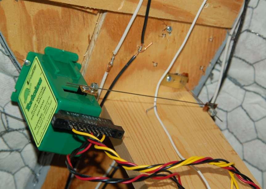
15 Add PCB Edge Connector Allows remote (and accessible) layout connections 10 Position Connectors were $0.50 at All Electronics Easy removal w/o risk of board damage Layout connections at more accessible location
16 Use two power supplies w/ Common ground 12 volts 12 vdc DC 12 vdc SPDT switch LEDs (optional) (indicate switch position Tortoise Common ground wire Makes wiring much simpler, only one wire to each Tortoise Common ground not for DCC, but helpful for accessory wiring Common ground wire not shown in wiring diagrams Switch can be toggle, rotary, slide, or relay Beware of make before break switches!
 should conduct, N to P should not.")
17 Simple Electrical Tester Here to ground, check continuity, etc LED (any) Here to ground to check LED s 330 ohm resistor 9 volt battery Check which contacts are closed on Tortoise, relays, etc Can also test transistors, on PNP, P to N (emitter and collector to base) should conduct, N to P should not. NOTE: 3 volt battery, 100 ohm resistor safer, LED s not rated for 9 volts in reverse

18 My layouts used rotary switches for twin coil switch machines. Turn knob then push button, knob showed turnout position. This technique worked well for years before changing to Tortoise machines.

19 LEDs indicate turnout position Rotary switches for turnout control Buttons leftover from old twin solenoid machines Reversing for tail track Not needed 4 pole 3 pos. Rotary switch Controls turnout and wye tail Track polarity, center is track off
 Controls 3 Turnouts Green LED s show turnout alignment Red LEDs show track")
20 Control Panel for Hidden Staging Yard Occupancy (Entrance Section) Track Power Direction (Reversing Section) Rotary Switch (3 pole 4 Pos) Controls 3 Turnouts Green LED s show turnout alignment Red LEDs show track occupancy
21 Staging Yard Tortoise Wiring Track Layout T-A T-C T-B Tk 4 Tk 3 Tk 2 Tk 1 LED 560 Ohms +12 VDC + 12 VDC -12 VDC + 12 VDC -12 VDC A B + 12 VDC -12 VDC C 3 Pole 4 Pos Rotary Switch Each Pole shown separately
22

23 These are for twin coil machines Same circuit, rev. section Conventional Wiring Simple transistor/relay circuits operated by push buttons on this panel permit controlling Tortoises from several locations and via a diode matrix, route selection. The LED s show turnout position and/or route selected.
24 Turnout Control from Multiple Locations and Route Selection On following circuits, while one button is shown, any number of buttons can be wired in parallel to control the relay (and Tortoise) from several locations. The first three circuits default to the relay off turnout position when layout power is turned off or interrupted. All Circuits can be used for anything that requires operating a relay from several locations PC relays require care in soldering connections to avoid overheating and damaging relay
25 Simple Transistor Circuit Resistor allows transistor to conduct Per Transistor specs, Up to 5000 ohms OK On button powers relay, stick contacts hold it on Off button shorts relay coil, so it drops out -12 volts DC +12 volts DC Diode 1N4004 * Relay On Off Resistor 1500 ohms To Tortoise Stick contacts Relay 12 volt 150 ohm coil * PNP Transistor 2N3906 (All Elect.) RS * not critical

26 Two 3 amp Power Supplies Diode Matrix to select turnouts Transistor circuits to control turnouts
27 Control Tortoise with 5 volt Relay (No personal experience) On Button powers relay, stick contact holds it on Off button bypasses relay coil so it drops out Can have any no. of on & off buttons in parallel Resistor matched to relay coil so about 7 volt drop, ½ watt at 12 volts Relays $1 to $1.50 ea. at All Electronics -12 volts DC +12 volts DC On Relay Off Resistor 270 ohms ½ watt To Tortoise Relay stick contacts Relay AE RLY v 178 ohm DPDT
28 Hysteresis Circuit (no personal experience) -12 volts DC To Tortoise This relay pulls in at 6 volts, drops out at 3 volts 300 ohm resistor selected so 4.5 volts on relay coil Resistor must be matched to relay coil +12 volts DC Off Relay On Beware that if both buttons are pushed at once, a short will result. There should be some sort of current limiter in circuit (eg, an auto taillight bulb.
29 Latching Relays A relay an electromechanical switch. It is used to control a large current with a small current. Most relays require a small continuous control current to stay on. A latching relay is different. It uses a voltage pulse to cycle the relay, then stays in this position until the opposite control voltage is applied. The latching relay has a small metal strip which can pivot between two terminals. The switch is magnetized, or attached to a small magnet. On either side of that magnet are small coils of wire. The two coils are used to control the relay. When electric current flows into one coil, it generates a magnetic field, which moves the switch from one side to the other. When the power is removed from the coil, the strip stays there until it receives a magnetic pulse in the opposite direction. This may come either from the other coil or from a current with the opposite polarity in the original coil, pushing the switch back to the other terminal.


30 Latching Relay - Typical $2.71 ea. Sample from Digikey Catalog Use set & reset coils to reverse Permits multiple control locations & Route control w/diode matrix IE very simple, versatile But 10 terminals on 9/16 x 5/16 base
 Track")
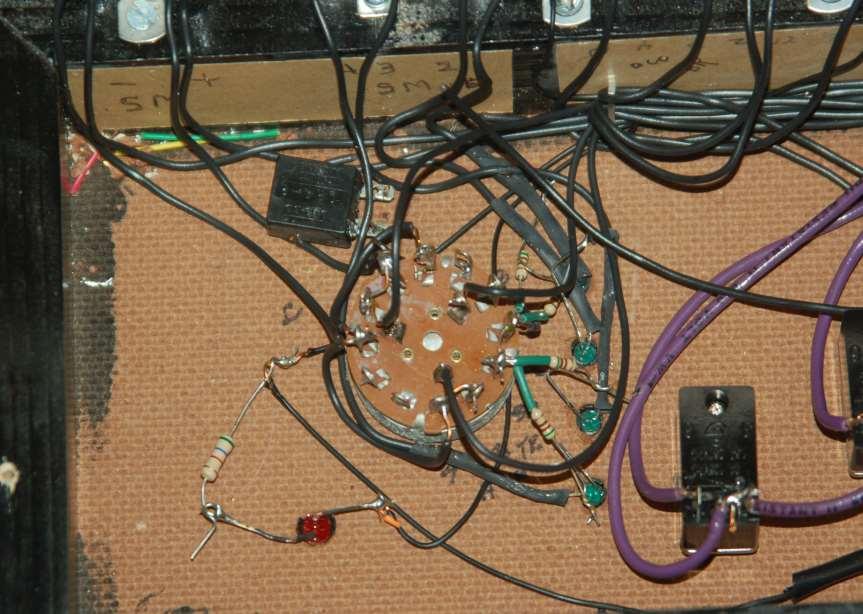
31 Panel for Latching Relays Power, +, gnd, - 12 vdc Relay To Switch Machines #24 wire relay to pin Escutcheon Pins Handy as terminals Input from Panel Buttons (Diode matrix under HS tubing) Track Schematic

32 Susquehanna Panel (Modified since earlier slide) Buttons select track, LED s show current turnout positions
33 Further information is available (or comments, criticism, etc) Phone, , or visit Hendersonville Gordon Fewster Ontario Southern Railway (828)
Model Railway Reverse Loops How to automate reversing tracks on your two-rail layout, whether DC, DCC or AC powered
 Model Railway Reverse Loops How to automate reversing tracks on your two-rail layout, whether DC, DCC or AC powered Because of the way power is supplied to electric model trains, two-rail layouts require
In this installment we will look at a number of things that you can do with LEDs on your layout. These will include:
 Introduction The first article in this series, LEDs 101 - The Basics, served to review the characteristics and use of LED lighting in a garden railway environment. It also generated a host of questions
Los Angeles Model Railroad Society. Wiring A Tortoise Switch Machine for the Mainline
 Los Angeles Model Railroad Society Wiring A Tortoise Switch Machine for the Mainline Ira Abramowitz 2/27/2010 1 INTRODUCTION...3 1.1 LET S START...3 2 MECHANICAL MOUNTING...4 2.1 MECHANICAL MOUNTING OPTIONS...4
Azatrax MRX3 Grade Crossing Signal Controller Installation Guide
 Azatrax MRX3 Grade Crossing Signal Controller Installation Guide What it is: The MRX3 is a sophisticated controller that realistically operates model railroad / highway crossing signals. The MRX3 includes
Bill Conkling July 2012
 Bill Conkling July 2012 Introduction: For any ham, there are moments that are priceless, like snagging that elusive rare DX station on a deserted island that hasn t been activated in 52 years. And certainly,
Explanation 1 Input External Switch 2 Input Hipot Safety Switch
 on the 1100H+ The 1100H+ has capability, which allows you to set up the tester to control external devices with tester functions. You can also use an input on the tester to start a test. For example, the
Sensors W2 and E2 are optional. Installation guide, 'Pickle Fork' Back-and-Forth Model Train Controller
 Installation guide, 'Pickle Fork' Back-and-Forth Model Train Controller Azatrax model PFRR-NTO This controller can automate a single track 'back-and-forth' model train layout -- or, one train can travel
UNIT 3: GENErAL ELECTriCAL SySTEM DiAGNOSiS
 Electrical/Electronic Systems UNIT 3: GENErAL ELECTriCAL SySTEM DiAGNOSiS LESSON 3: TEST electrical circuits I. Types of electrical circuit tests and electrical faults A. Different types of electrical
Contacts The moveable contact, which is the one affected by the armature is sometimes referred to as the hinge contact.
 Relays & Wiring 101 Basically, a relay is an electrically operated, remotely controlled switch. A simple electromagnetic relay is an adaptation of an electromagnet. It consists of a coil of wire surrounding
REC-11+ REMOTE RECEIVER UNIT
 Resetting The Programmable Features The installer may quickly and easily return all 17 programmable features back to the factory settings. Changing individual features were explained in detail in the previous
Cross Hare Installation Guide
 Cross Hare Installation Guide Introduction: The Cross Hare is designed to provide all of the functions you need to control a one or two track grade crossing in a prototypical manner. The Cross Hare uses
Operation and Installation Manual
 Operation and Installation Manual G-Scale Graphics 4118 Clayton Ct. Fort Collins, CO 80525 970-581-3567 GScaleGraphics@comcast.net www.gscalegraphics.net Revision C: Updated 7/15/2009 Page Overview The
Rigid Base / Turntable Bed. Exploded side view of bottom rotating wood drive wheel, showing optics aligned to stop bracket.
 TURNTABLE INDEXER #617 for use with BOWSER and other, turntables by 246 W. Main St. Leola, PA 17540 (717) 661-7041 www.dallee.com OVERVIEW The TURNTABLE INDEXER unit has been made with simplicity of installation
Basic Electricity. Mike Koch Lead Mentor Muncie Delaware Robotics Team 1720 PhyXTGears. and Electronics. for FRC
 Basic Electricity and Electronics for FRC Mike Koch Lead Mentor Muncie Delaware Robotics Team 1720 PhyXTGears The Quick Tour The Analog World Basic Electricity The Digital World Digital Logic The Rest
Contents. DX Ignition Page 2
 Contents 1.0 Intent 2.0 Specifications 3.0 Installation 4.0 Operation Precautions 5.0 Repair 6.0 Parts List 7.0 Glossary of Terms 8.0 Contact Information DX Ignition Page 2 1.0 Intent The purpose of this
Unit AE01K Knowledge of Locating and Correcting Simple Electrical Faults in the Automotive Workplace
 Assessment Requirements Unit AE01K Knowledge of Locating and Correcting Simple Electrical Faults in the Automotive Workplace Content: Basic electrical principles a. Explain the direction of current flow
E D C K R A E T S I D TURNOUT CONTROLLER 8S USER MANUAL
 S I D E T R A C K E D TURNOUT CONTROLLER 8S USER MANUAL INDEX 1. WHAT YOU SHOULD HAVE 3 2. FEATURES OF THE 3 3. WARRANTY 3 4. ABOUT THIS MANUAL 3 5. CONNECTORS AND DESCRIPTIONS 3 6. WIRING 7 6.1. CONTROL
Control Relays Overview
 Control Relays Overview DESIGN FEATURES Among the advances Agastat Control Relays offer over existing designs is a unique contact operating mechanism. An articulated arm assembly amplifies the movement
RR Concepts. The StationMaster can control DC trains or DCC equipped trains set to linear mode.
 Jan, 0 S RR Concepts M tation aster - 5 Train Controller - V software This manual contains detailed hookup and programming instructions for the StationMaster train controller available in a AMP or 0AMP
ELECTRIC SCHEMATICS LS1 LS2. "1532ES / 1932ES" Service & Parts Manual - ANSI Specifications March 2008 Page 5-9 ART_2236 ART_2243
 ELECTRIC SCHEMATICS NOTES: (Unless otherwise specified). Switch S BASE/PLATFORM makes contact from the CENTER to the LEFT position when placed in BASE.. Switch S UP/DOWN makes contact from the CENTER to
ELECTRONICS & HWH 19APR11
 ELECTRONICS & HWH 19APR11 1. PREFACE This section deals with electronic equipment and components. We will discuss common electronic components and components that are specific to HWH. The discussion will
Build a Simple Handheld Throttle for the Digitrax Zephyr
 Build a Simple Handheld Throttle for the Digitrax Zephyr Here is a way to build a simple three button throttle for use with the Digitrax popular Zephyr. This handheld throttle is designed work with the
Security alarms, warning systems.
 SIREN DRIVER BOARD. Free running siren activated by the application of a V DC power source. This module is capable of driving a maximum of 2 x 8 ohm 10W speakers and produces approximately 110 db at one
Turnout Motors from Servos
 Turnout Motors from Servos An article by Jim Lomison in the January, 2011 issue of Model Railroader [1] describing the use of motors from servomechanisms to drive turnout points sparked an interest, principally
QUASAR ELECTRONICS KIT No ELECTRONIC CAR IGNITION
 QUASAR ELECTRONICS KIT No. 1058 ELECTRONIC CAR IGNITION General Description The advantages of having an electronic ignition in your car are well known. Let us mention them again: 1. Perfect burning of
PEOPLE ARE FAMILIAR WITH THE CONCEPT OF RUNNING A LIGHT FROM A BATTERY AND THEN RECHARGING THE BATTERY USING A SOLAR PANEL OR A WIND-POWERED GENERATOR
 A Perpetual Light PEOPLE ARE FAMILIAR WITH THE CONCEPT OF RUNNING A LIGHT FROM A BATTERY AND THEN RECHARGING THE BATTERY USING A SOLAR PANEL OR A WIND-POWERED GENERATOR. HOWEVER, WE REALLY WANT TO BE ABLE
Operation and Installation Manual
 Operation and Installation Manual G-Scale Graphics 5860 Crooked Stick Dr. Windsor, CO 80550 970-581-3567 GScaleGraphics@comcast.net www.gscalegraphics.net Revision A: Updated 2/7/2018 Page Overview The
3-Phase Motor Demo. R Hoadley 10 Oct 2009
 3-Phase Motor Demo R Hoadley www.coolmagnetman.com 10 Oct 2009 1 Basic Layout 2 3 4 Each Electromagnet 5 Each Electromagnet The electromagnets I had were: About ¾ diameter core About 1-3/16 long About
4 Electric Circuits. TAKE A LOOK 2. Identify Below each switch, label the circuit as a closed circuit or an open circuit.
 CHAPTER 17 4 Electric Circuits SECTION Introduction to Electricity BEFORE YOU READ After you read this section, you should be able to answer these questions: What are the three main parts of a circuit?
Your Layout. With LED Tape
 Your Layout With LED Tape Overview What is LED Tape Lighting? A continuous strip of surface mount device (SMD) light emitting diode (LED) semiconductor devices, wired in parallel, with integral current
Aword used for circuits in which one device operates the next in sequence. An electrical control device for opening and closing circuits.
 INTRODUCTION Various methods of controlling electrically operated switch machines are covered in this group of sheets. Included in the first are basic circuits and in the others Sheet #: Updated by: Updated:
SM361 RIG SWITCH CONSTRUCTION MANUAL
 SM361 RIG SWITCH CONSTRUCTION MANUAL Document ver 1, For software release ver 1.1 May 27, 2016 Controls the power of 12V equipment while a vehicle is in use Product Development by: SM361 RIG SWITCH OVERVIEW
LV101 DCC Power Station
 LV101 Power Station 1 Ultra clean DCC Track Power Adjustable DCC Track Voltage Opto-isolation interface for Safety Short and overload protection Designed to meet Proposed NMRA Power Station Interface RP
123\SmartBMS. 123\SmartBMS manual V1.3. Albertronic BV The Netherlands
 123\SmartBMS 123\SmartBMS manual V1.3 Index Introduction... 2 Keep the batteries in perfect condition... 3 Package contents... 4 Specifications... 4 Placing the cell modules... 5 Mounting the IN Module...
Simple Free-Energy Devices
 Simple Free-Energy Devices This presentation is mainly for people who have never come across free-energy and know nothing about it. So, each chapter deals with just one device and tries to explain it clearly.
Yaskawa Electric America Unit Troubleshooting Manual Section One: Introduction & Checks Without Power GPD 506/P5 and GPD 515/G5 (0.
 Yaskawa Electric America Unit Troubleshooting Manual Section One: Introduction & Checks Without Power GPD 506/P5 and GPD 515/G5 (0.4 ~ 160kW) Page 1 Introduction This manual is divided into three sections:
Simple Free-Energy Devices
 Simple Free-Energy Devices There is nothing magic about free-energy and by free-energy I mean something which produces output energy without the need for using a fuel which you have to buy. Chapter 4:
ELECTRICAL. Contents - Wiring Diagrams
 Contents - Wiring Diagrams T-Bar (Floating Deck - Hydro)............................................ 8-16 T-Bar (Fixed Deck - Gear)............................................... 8-17 T-Bar (Fixed Deck
12VPS TRAK-DT. Block Detection / Signaling Starter Package. 12 VOLT / 0.5 Amp REGULATED POWER SUPPLY. a c t i v a t i o n s e c t i o n
 Block Detection / Signaling Starter Package This package includes 3 Trak-DT's (item 365) and one 12VPS (item 369), 12 volt DC regulated power supply. Drawings are included for basic two and three aspect
REMOTE OPERATION OF POINTS
 REMOTE OPERATION OF POINTS or turnouts - the terms can be used Interchangeably) an essential Ingredient for reliable operating sessions. This issue we focus on electrically-operated point motors encompassing
J1 Plug Pin Identification
 D5 D D D D5 D ART_ J D D0 R R R R TB 0 D D D D D D J Plug Pin Identification PIN # WIRE # SIGNAL FUNCTION 0 INPUT Drive Reverse INPUT Drive Forward OUTPUT Brake, Decel Valve signal INPUT Steer Left 5 OUTPUT
VSO Thermally Compensated Proportional Valve
 4 VSO Thermally Compensated Proportional Valve Typical Applications Gas Chromatography Mass Spectrometry Ventilators O 2 Concentrators/Conservers Anaesthesia Delivery & Monitors Pressure & Control Mass
QUASAR KIT No THYRISTOR - TRIAC TESTER
 QUASAR KIT No. 1087 THYRISTOR - TRIAC TESTER GENERAL DESCRIPTION With this new kit Quasar Kit offers you a very useful instrument for your bench that will help you to test THYRISTORS and TRIACS. These
Miniature Proportional Valve Thermally Compensated Proportional Valve. Physical Properties
 VSO Miniature Proportional Valve Thermally Compensated Proportional Valve Typical Applications Gas Chromatography Mass Spectrometry Ventilators O 2 Concentrators/Conservers Anaesthesia Delivery & Monitors
POWER SUPPLY MODEL XP-800. TWO AC VARIABLE VOLTAGES; 0-120V and 7A, PLUS UP TO 10A. Instruction Manual. Elenco Electronics, Inc.
 POWER SUPPLY MODEL XP-800 TWO AC VARIABLE VOLTAGES; 0-120V and 0-40V @ 7A, PLUS 0-28VDC @ UP TO 10A Instruction Manual Elenco Electronics, Inc. Copyright 1991 Elenco Electronics, Inc. Revised 2002 REV-I
Ch 4 Motor Control Devices
 Ch 4 Motor Control Devices Part 1 Manually Operated Switches 1. List three examples of primary motor control devices. (P 66) Answer: Motor contactor, starter, and controller or anything that control the
Grout Pump Automatic & Manual Troubleshooting Gas Wiring Diagram
 Grout Pump Automatic & Manual Troubleshooting 40-500 Gas Wiring Diagram Turn engine off and relieve hydraulic pressure and grout pressure before troubleshooting. Note: Typically there is a wiring diagram
Miniature Proportional Valves Precision Fluidics
 Precision Fluidics 2 Electronic Pressure Control When you partner with the global leader in motion and control technologies, expect to move your business and the world forward. From miniature solenoid
J1 Plug Pin Identification
 D5 D8 D7 D4 D5 D ART_8 J 4 8 D D0 7 R R R R4 TB 80 D D D D4 D D J Plug Pin Identification PIN # WIRE # SIGNAL FUNCTION 0 INPUT Drive Reverse INPUT Drive Forward OUTPUT Brake, Decel Valve signal 4 8 INPUT
INSTALLATION MANUAL FOR
 MOUNTING LOCATION Reader RD- FOR RF CONTROLLER VIZIT-KTM60 R, EXIT 00M BUTTON This manual is intended as an addition to operating instructions on your access control system (ACS) units to guide through
Systems: Electronics
 Systems: Electronics Resistors & Capacitors Units for resistors and capacitors size/component small large resistance ohm kilohm megaohm capacitance picofarad microfarad farad current milliampere Ampere
Series BFM Bulk Flow Monitor 1A FUSE RED LED RELAY. Part Number BFM-1 BFM-2 BFM-3 BFS-1
 Series Bulk Flow Monitor Specifications - Installation and Operating Instructions Bulletin FL-1-4x 3/4 CONDUIT KNOCKOUTS BFS 1A FUSE RED LED RELAY 5-9/64 [130.45] TRANSFORMER 3[76.20] GREEN LED 7 [177.80]
Price List May Realism is what we aspire to achieve. This List gives you an idea of what else we do.
 Brimal also supply a complete range of Electronic Components and Tools for your hobby. Please ring 01429 297277 for all sales. This List gives you an idea of what else we do. Audio Cable PCB Terminals
IMI vibration switch USER MANUAL INSTALLATION - OPERATION - MAINTENANCE
 USER MANUAL IMI vibration switch INSTALLATION - OPERATION - MAINTENANCE Z0929039_A ISSUED 03/2017 READ AND UNDERSTAND THIS MANUAL PRIOR TO OPERATING OR SERVICING THIS PRODUCT. contents Overview General
Note: Do NOT mix LED and incandescent lamps in the same circuit!
 Light Up Your Modified Car Some Hot Rod lights are hard to see. Your teardrop lights may look cool, but the 5W incandescent lamp that came with it just doesn t light up bright enough to show others you
Worksheet 1 - Simple digital sensors 3. Worksheet 2 - Lamps and simple actuators 6. Worksheet 3 - Using transistors 8. Worksheet 4 - Relays 10
 Contents Worksheet 1 - Simple digital sensors 3 Worksheet 2 - Lamps and simple actuators 6 Worksheet 3 - Using transistors 8 Worksheet 4 - Relays 10 Worksheet 5 - Analogue inputs 12 Worksheet 6 - Fault
Solid-State Relays. Solid-State Relays. Features. Description. Overview
 Features Rugged, epoxy encapsulation construction 4,000 volts of optical isolation Subjected to full load test and six times the rated current surge before and after encapsulation Unique heat-spreader
User Manual. BMS123 Smart
 User Manual BMS123 Smart Introduction After the introduction of affordable LiFePO4 batteries, off-grid solutions became available for wide public. It is vital that such batteries are charged very carefully.
ZTC 335 Dual Track Detector Installation Manual
 ZTC 335 Dual Track Detector Installation Manual WARNING If you fail to read the installation instructions properly it is possible that you could accidentally damage your ZTC unit. Such damage is NOT covered
AUSTRALIA (04) PHONE: INTERNATIONAL # MRW-SSLS
 PHONE: INTERNATIONAL # MRW-SSLS") R/C SWITCHES PO BOX 8 BAYSWATER, VIC 353, AUSTRALIA PHONE: INTERNATIONAL ++64 2902 9083 AUSTRALIA (04) 2902 9083 Web: http://www.rcs-rc.com Email: rcs@rcs-rc.com # MRW-SSLS # MRW-SSLS by Model Radio Workshop
R/C SWITCHES PO BOX 8 BAYSWATER, VIC 353, AUSTRALIA PHONE: INTERNATIONAL ++64 2902 9083 AUSTRALIA (04) 2902 9083 Web: http://www.rcs-rc.com Email: rcs@rcs-rc.com # MRW-SSLS # MRW-SSLS by Model Radio Workshop
Miniature Proportional Valve. Non-Thermally Compensated Proportional Valve
 MD PRO Miniature Proportional Valve Non-Thermally Compensated Proportional Valve Typical Applications O 2 Concentrators/Conservers Ventilators Anaesthesia Delivery Pressure & Control Patient Monitors The
INSTRUCTIONS. DO NOT CONNECT TO MAINS POWER ( V AC).
.") P.O Box 578 Casino, NSW, 2470 Australia Phone: International ++614 2902 9083 Australia (04) 2902 9083 Website: http://rcs-rc.com E mail: Info@rcs-rc.com ALPHA-3v2 Electronic Speed Controller Supplied for
P.O Box 578 Casino, NSW, 2470 Australia Phone: International ++614 2902 9083 Australia (04) 2902 9083 Website: http://rcs-rc.com E mail: Info@rcs-rc.com ALPHA-3v2 Electronic Speed Controller Supplied for
BMS-LiFePower. 123SmartBMS. Instruction manual
 BMS-LiFePower 123SmartBMS Instruction manual Index Introduction...2 Keep the batteries in perfect condition...2 Package contains (12 Volt, 4 cells)...3 Specs...3 Placing the cell modules...4 Mounting the
Circuit Basics and Components
 Circuit Basics Electric circuits are arrangements of conductors and components that permit electrical current to flow. A circuit can be as simple as a battery and lamp or as sophisticated as a computer.
INSTRUCTIONS. DO NOT CONNECT TO MAINS POWER ( V AC).
.") P.O Box 578 Casino, NSW, 2470 Australia Phone: International ++614 2902 9083 Australia (04) 2902 9083 Website: http://rcs-rc.com E mail: Info@rcs-rc.com TABLE OF CONTENTS PROVIDED IN INSTRUCTIONS. Page
P.O Box 578 Casino, NSW, 2470 Australia Phone: International ++614 2902 9083 Australia (04) 2902 9083 Website: http://rcs-rc.com E mail: Info@rcs-rc.com TABLE OF CONTENTS PROVIDED IN INSTRUCTIONS. Page
ches UL File No. E101598
 Instrument Transformers, Inc. Series Series 95 95 Swit Switches ches UL File No. E101598 INSTRUMENT AND CONTRC ONTROL OL s Instrument and Control Switch is a heavy-duty rotary switch that satisfies the
ICA Manufacturing Catalog. Your One Stop Metal Shop. Table of Contents. Visit us at:
 ICA Manufacturing Your One Stop Metal Shop At ICA Manufacturing, you will find high-quality creations and wholesale parts at a budget price. From Aluminum Cabinetry, to Transformers, to Capacitors, we
Product Manual MNX10010 / REV B MODEL PS03
 Product Manual MNX10010 / REV B MODEL PS03 3-Channel Power Supply Contents Section I Overview Introduction.... 2 Description... 2 Section II Installation Installation... 5 Section III Operation Operating
3 Slot Payphone Controller
 S Coin Controller 2A Information on your Telephone For Your Records Manufacturer Date of Original Manufacture Drawing Reference One of the original patents --- US 2,043,201 This Telephone is Property of
INSTRUCTIONS. DO NOT CONNECT TO MAINS POWER ( V AC).
.") P.O Box 578 Casino, NSW, 2470 Australia Phone: International ++614 2902 9083 Australia (04) 2902 9083 Website: http://rcs-rc.com E mail: Info@rcs-rc.com TABLE OF CONTENTS PROVIDED IN INSTRUCTIONS. Page
P.O Box 578 Casino, NSW, 2470 Australia Phone: International ++614 2902 9083 Australia (04) 2902 9083 Website: http://rcs-rc.com E mail: Info@rcs-rc.com TABLE OF CONTENTS PROVIDED IN INSTRUCTIONS. Page
Model 2300DL Installation Guide
 Model 2300DL Installation Guide POWER ACCESS CORPORATION 4 HERSHEY DRIVE, DOCK 4 ANSONIA, CT 06401 800-344-0088 WEBSITE: www.power-access.com EMAIL: salesinfo@power-access.com 1 STANDARD PARTS MODEL 2300DL
USING WEATHERLINK FOR ALARM OUTPUT Application Note 29
 USING WEATHERLINK FOR ALARM OUTPUT Application Note 29 With Vantage Pro and Vantage Pro2 INTRODUCTION WeatherLink for Alarm Output can be incorporated in any Vantage Pro or Vantage Pro2 weather station.
ELECTRICITY AND HWH COPPER CONDUCTOR
 1. PREFACE +BATTERY TERMINAL +BATTERY TERMINAL + + + + + + + + + + + + ELECTRICITY AND HWH In the first section of this school, we did an in-depth study of general hydraulics. In section four, we applied
Maintenance Instructions & Parts List
 PM-PTR/LTR-C Automation Actuator Division Wadsworth, Ohio 448 October 7, 993 Rev. October 999 PTR/LTR Series Actuators Maintenance Instructions & Parts List Provide Model Number and Serial Number When
1.0 Installation Wiring
 1.0 Installation Wiring DX Firebox is designed to be an electronic replacement for Pontiac & Ford buzz coils when operated on DC. Installation may be positive or negative ground. Simply observe the RED
Electrical Systems. Introduction
 Electrical Systems Figure 1. Major Components of the Car s Electrical System Introduction Electricity is used in nearly all systems of the automobile (Figure 1). It is much easier to understand what electricity
J1 Plug Pin Identification
 D D8 D D D D ART_8 J 8 D D0 R R R R TB 80 D D D D D D J Plug Pin Identification PIN # WIRE # SIGNAL FUNCTION 0 INPUT Drive Reverse INPUT Drive Forward OUTPUT Brake, Decel Valve signal 8 INPUT Steer Left
TTT802 Gearshift Controller, Part # R1N-S (Standard), -P (Paddleshift)
, -P (Paddleshift)") First, Sign and Date Bln 2009-03-9 Updated, Sign and Date Bln 200-04-29 (0) User Manual TTT802 Gearshift Controller Firmware for R--N-2- TTT802 Gearshift Controller, Part # 2-620-9-RN-S (Standard), -P
First, Sign and Date Bln 2009-03-9 Updated, Sign and Date Bln 200-04-29 (0) User Manual TTT802 Gearshift Controller Firmware for R--N-2- TTT802 Gearshift Controller, Part # 2-620-9-RN-S (Standard), -P
2007-UP NAVIGATION INTERFACE MODULE (Infiniti/Nissan)
") 2007-UP NAVIGATION INTERFACE MODULE (Infiniti/Nissan) ALTHOUGH THIS PRODUCT HAS BEEN THOROUGHLY TESTED KPIERSON TECHNOLOGIES ASSUMES NO RESPONSIBILITY FOR ANY DAMAGE THAT MAY RESULT BY THE INSTALLATION
2007-UP NAVIGATION INTERFACE MODULE (Infiniti/Nissan) ALTHOUGH THIS PRODUCT HAS BEEN THOROUGHLY TESTED KPIERSON TECHNOLOGIES ASSUMES NO RESPONSIBILITY FOR ANY DAMAGE THAT MAY RESULT BY THE INSTALLATION
SERIES 700/700E FACTORY KEYLESS UPGRADE INSTALLATION MANUAL
 SERIES 700/700E FACTORY KEYLESS UPGRADE INSTALLATION MANUAL Items Supplied with the System: Installation Instructions: Main unit 1. Mounting the module: Plug In LED Mount the module in a suitable location
Detailed Explanation of Function of AF 695 Reverse Loop Relay
 June 24, 2017 Detailed Explanation of Function of AF 695 Reverse Loop Relay The American Flyer (AF) Reverse Loop Relay sold for $ 2.95 and $ 3.95 respectively when manufactured in 1955 and 1956. The Reverse
CHAPTER 2. Current and Voltage
 CHAPTER 2 Current and Voltage The primary objective of this laboratory exercise is to familiarize the reader with two common laboratory instruments that will be used throughout the rest of this text. In
2xVCX version 1.0. Calibration instructions can be found on the last page. Capacitor bypass MLCC X7R mm pin pitch
 Produced by: Roll Your Own ljunggrenaudio.com Schematic & PCB Design by: KYMATICA DEVICES www.kymatica.com xvcx version.0 Bills Of Material Bold = PCB C C C3 C4 C5 C6 C7 C8 C9 C0 C C C3 C4 CON D D D3 D4
C capacitance, 91 capacitors, codes for, 283 coupling, polarized and nonpolarized,
 Index Numbers and Symbols 555 timer, 164 166 making sound using, setting output speed of, 166 167 using for reaction game speed, 260 261 μf (microfarad), 92 Ω (ohms), 7, 70 A A (amperes), 7 AC (alternating
solutions for teaching and learning
 SCR/Thyristor Training PCB Component List and Instructions Version 2 PCB layout Constructed PCB SCR Training and Development PCB Page 1 Schematic Diagram Description This system has been specifically designed
C-PIM701 (Police Interface Module) 2018 Dodge Charger Pursuit
 2018 Dodge Charger Pursuit") An ISO 9001:2008 Registered Company C-PIM701 (Police Interface Module) 2018 Dodge Charger Pursuit Introduction The Police Interface Module is intended to provide Dodge Chargers with multiple desired functions
An ISO 9001:2008 Registered Company C-PIM701 (Police Interface Module) 2018 Dodge Charger Pursuit Introduction The Police Interface Module is intended to provide Dodge Chargers with multiple desired functions
Learning Objectives:
 Topic 5.5 High Power Switching Systems Learning Objectives: At the end of this topic you will be able to; recall the conditions under which a thyristor conducts; explain the significance of the following
Devices installed in a race car should be divided into two categories: power devices and control devices.
 With the never-ending quest for more horsepower and faster cars, today s racecars have more electronics than ever. To create more horsepower, cylinder pressures must rise. To fire the cylinders under these
DCC 102. DCC Power Districts and Short Circuits By Dennis Turner, Superintendent Denver s RailRoads.
 DCC 102 DCC Power Districts and Short Circuits By Dennis Turner, Superintendent Denver s RailRoads http://denversrailroads.com/ Introduction We will cover in this clinic: Power Districts Short Circuits
Phone: Fax: ILD Series. Troubleshooting: ILD Column Lift
 15939 Piuma Avenue Cerritos, CA 90703 ILD Series Troubleshooting: ILD Column Lift Table of content: Page 1) Gate overview...2 2) Single Motor Setup overview. 3 3) Dual Motor Setup overview....4 4) Gate
G203V / G213V MANUAL STEP MOTOR DRIVE
 G203V / G213V MANUAL STEP MOTOR DRIVE PRODUCT DIMENSIONS PHYSICAL AND ELECTRICAL RATINGS Minimum Maximum Units Supply Voltage 18 80 VDC Motor Current 0 7 A Power Dissipation 1 13 W Short Circuit Trip 10
INSTRUCTION MANUAL VIBRASWITCH MALFUNCTION DETECTOR MODEL 366
 INSTRUCTION MANUAL VIBRASWITCH MALFUNCTION DETECTOR MODEL 366 Industrial Products 1602 Mustang Drive Maryville, Tennessee 37801 Phone: (865) 981-3100 Fax: (865) 981-3168 http://www.robertshawindustrial.com
RS-351-EDP. Installation Guide
 RS-351-EDP Keyless Entry & Remote Start Installation Guide June 25, 2013 Temporary cover. Color cover is in a separate file. Table Of Contents Installation Considerations... 3 6 Pin Main Wire Harness...
User manual. BMS123 Smart
 User manual BMS123 Smart Introduction After the introduction of affordable LiFePO4 batteries, off-grid solutions became feasible. It is vital that such batteries are charged very carefully. In other words,
Single or Double 240VAC motor control for domestic and industrial gates and doors.
 COBO30 Double 240V Motor Drive Controller Features For 240Volt Motors Auto Closing Open Only Security Closing and Extended Lock Pulse (user selectable) Travel Timer Push Button Input Photo Cell Input Option
SR-400 CYCLONE TO SR-400 CYCLONE II UPGRADE WRITTEN BY WDØGOF
 SR-400 CYCLONE TO SR-400 CYCLONE II UPGRADE WRITTEN BY WDØGOF This upgrade assumes you are starting with a first production run Cyclone. As you proceed you may find some of the modifications have already
elabtronics Voltage Switch
 elabtronics Voltage Switch Want to trigger a device when a monitored voltage, temperature or light intensity reaches a certain value? The elabtronics Voltage Switch is an incredibly easy way of doing it.
LG Air Conditioning Universal & Multi Split Fault Codes Sheet. Universal and Multi Split Units
 Universal and Multi Split Units If there is a fault on any LG Universal or Multi unit, a two digit number will appear on the remote controllers led display. If the unit does not have a remote controller
Chrysler Electronic Ignition System
 1 of 11 1/6/2010 11:02 PM Chrysler Electronic Ignition System Classic Winnebago's Post by: DaveVA78Chieftain on August 13, 2009, 10:15 PM Components The Chrysler Electronic Ignition System consists of
Parts List DIY-81 rev 1. Capacitors. DIY-81 Project Parts list rev 1
 Electrolytic C100 100 25 Axial 8 x 100uF/25V Axial C101 150 16 Axial 8 x 150uF/16V Axial C102 150 16 Axial 2 x 470uF/16V Radial C18 470 16 Radial C103 150 16 Axial C104 150 16 Axial C106 100 25 Axial C105