ches UL File No. E101598
|
|
|
- Abner Nash
- 6 years ago
- Views:
Transcription


1 Instrument Transformers, Inc. Series Series Swit Switches ches UL File No. E101598

2 INSTRUMENT AND CONTRC ONTROL OL s Instrument and Control Switch is a heavy-duty rotary switch that satisfies the most demanding requirements of the industrial control and power applications. These switches are 600V AC rated and are recognized by Underwriters Laboratories in the United States and Canada. Some of the typical standard applications for the Series 95 are: Circuit-breaker control Motor control Voltmeter Selector and Transfer Ammeter Selector and Transfer Synchroscope Control Control Selector Switch Applications The Series 95 switches have the following standard features: Standard 3-hole Mounting #8-3 screw terminals Nema class A Insulating materials (105 0 C ) Silver contact surfaces for long reliable life Double-sided, double-wiping, knife-type rotary contacts Special Features for Circuit Breaker Control switches include: Mechanical red/green target Slip contact for alarm and indicator circuits Pull-to-Lock mechanism to return the switch handle to normal (vertical) position Selection of Lighted Escutcheon plates Special features for Meter Control switches include: Make-Before-Break (shorting contacts for ammeter control) Common-input Tap-Switch arrangement whereby the meter may be sequentially connected to several lines using the same switching deck Positive positioning detent mechanism Pre-wired jumpers Special features for synchroscope applications include: Removable Oval Handles Key lockable arrangements The following details the most common applications, contact arrangements and escutcheon plate markings. For combination of contact arrangements, handles, escutcheon plate marking and special features not shown, contact the factory for availability.


 LETTER APPEARING AFTER")
3 IIN NS ST TR RU UM ME EN NT T A AN ND D C CO ON NT TR RO OL L S SW WIIT TC CH H INSTRUMENT AND CONTROL ES.4.13 STOP SCREWS SUPPLIED TO D LIMIT ROTATION AS DESIRED.63 TYP 3.5 DIA DIA MAX PANEL OVAL HANDLE TYPICAL SCREWS 8-3 x 1/4 BD, HD SUPPLIED DEPTH BEHIND PANEL NUMBER OF DEPTH INCHES 1.4 INTERRUPTING RATING.9 0A-10 VAC A-40VAC A-600VAC DECKS UL File No. E D 3A-15VDC 1A-50VDC MAKE ONLY RATINGS: 75A- 10 VAC VAC 75A-4-15VDC 37.5A-50VDC Slip Contact - add 1.5 OPEN CONTINUOUS RATING - 30A-600V Pull - to- lock- Add 1.00 DIELECTRIC STRENGTH - 00VRMS (these are approximate dimensions) LETTER APPEARING AFTER MODEL NO i.e C PISTOL GRIP KNURLED C D OVAL B DIA OVAL - REMOVABLE E KEY LOCK T - HANDLE RH
4 INSTRUMENT AND CONTRC ONTROL OL ROTARY ES FOR INSTRUMENT CONTROL APPLICATION ESCUTCHEON TRANSFER Wire, Single Phase or D C ON Double Pole / Single Pole Throw Cat. No C Depth behind panel D - V14 TRANSFER 4 Phase, Two Phase or Two separated D C circuits 1 Double Pole / Double Throw Cat. No. 9540C Depth behind panel C-3V14 TRANSFER Phase, Phase to neutral Double Pole / Triple Throw Cat. No C Depth behind panel C -4V15 TRANSFER 3 Phase, Phase to Phase Double Pole / Triple Throw Cat. No C Depth behind panel C-4V1 TRANSFER 3 Phase, Phase to Phase and Phase to neutral Double Pole / Six Throw 1-1 Cat. No C Depth behind panel E -7V4 TRANSFER 6 Wire, Two 3 Phase circuit, Phase to Phase Double Pole / Six Throw Cat. No C Depth behind panel E - 8V33 3 Consult Factory for non-standard Escutcheon Plates
5 INSTRUMENT AND CONTRC ONTROL OL ROTARY ES FOR INSTRUMENT CONTROL APPLICATION ESCUTCHEON TRANSFER 3 Phase, 1 3 Two current Transformers Cat. No C Depth behind panel C- 3A10A TRANSFER 3 Phase, Two current Transformers 1 3 Cat. No C Depth behind panel C - 4A13 TRANSFER 3 Phase, 1 3 Three current Transformers Cat. No C Depth behind panel C - 3A10A TRANSFER 3 Phase, 1 3 Three current Transformers Cat. No C Depth behind panel C - 4A13 TRANSFER 3 Phase, Phase to Phase 1 3 and Phase to neutral Double Pole Six Throw 9510A-3A10 Cat. No C (NO ) 1 3 Cat. No. 9541C (WITH ) Depth behind panel C - 5A16 Consult Factory for non-standard Escutcheon Plates 4
6 INSTRUMENT AND CONTRC ONTROL OL ROTARY ES FOR INSTRUMENT CONTROL APPLICATION ESCUTCHEON - TRANSFER 3 Phase, Phase to Phase Three current Transformers Cat. No C Depth behind panel C-4A3C WATTMETER WATTMETER TRANSFER 3 Phase, ON Three current Transformers Three current Potential Transformers Cat. No C 9510D-W14 Depth behind panel 3.60 WATTMETER TRANSFER WATTMETER ON 3 Phase, Two current Transformers Two current Coils Two potentials Coils 9510D - W14 Cat. No. 9540C Depth behind panel 3.60 WATTMETER WATTMETER REVERSING W RVA Cat. No. 9541C Depth behind panel C-3W16 P.F. METER POWER-FACTOR ON 3 Phase, Two current Transformers One or Two current Coils Cat. No. 954C 9510D- P14 Depth behind panel.40 SYNCHROSCOPE SYNCHRONIZING ON Machine to bus with interlocks Handle: Oval, removable Cat. No. 9544E Depth behind panel D -S17 5 Consult Factory for non-standard Escutcheon Plates
7 INSTRUMENT AND CONTRC ONTROL OL ROTARY ES FOR INSTRUMENT CONTROL APPLICATION ESCUTCHEON MOTOR CONTROL GOVERNOR OR RHEOSTAT MOTOR CONTROL RAISE LOWER Split field motor Cat. No. 9547D Depth behind panel B-M Double Pole / Single Throw contacts normally open Cat. No D Depth behind panel D -1B18 CONTROL Cat. No D Depth behind panel B - B3 CONTROL Cat. No D Depth behind panel B -B3 CONTROL Operate two breaker Cat. No D Depth behind panel B -B3 CONTROL Operate two breaker Cat. No. 9544D Depth behind panel B -B3 Consult Factory for non-standard Escutcheon Plates 6
8 INSTRUMENT AND CONTRC ONTROL OL ROTARY SELECTOR ES APPLICATION ESCUTCHEON CONTROL Cat. No D Depth behind panel B -B3 CONTROL Cat. No D Depth behind panel B -B3 CONTROL Cat. No D Depth behind panel B -B3 CONTROL Cat. No D Depth behind panel B -B3 CONTROL PULL-TO LOCK Cat. No D Depth behind panel C-3B33 CONTROL Cat. No. 9545D PULL-TO LOCK Depth behind panel B -B3 7 Consult Factory for non-standard Escutcheon Plates
9 INSTRUMENT AND CONTRC ONTROL OL ROTARY SELECTOR ES APPLICATION ESCUTCHEON CONTROL UNIVERSAL CIRCUIT Cat. No D 9518B -B3 Depth behind panel 6.0 CONTROL UNIVERSAL CIRCUIT PULL-TO LOCK Cat. No D Depth behind panel C -B3 Consult Factory for non-standard Escutcheon Plates 8
10 INSTRUMENT AND CONTRC ONTROL OL DETENT SELECTOR DESCRIPTION STOPS CATALOG NUMBERS - ON ** The catalog numbers are for universal switches that provide all contacting shown. SINGLE - THROW Oval handle supplied. To limit switches to positions shown put limit screws in holes in rear stop plate shown as Stops. 1 Order jumpers as required, as separate items. 1 & 7 DECKS CATALOG NO. INCHES* B.4 DOUBLE 9540B.9 THROW B 3.6 (ON ) B B B B 6. 1 & B B 7.4 DOUBLE B 8.0 THROW * DEPTH BEHIND PANEL (WITH ) 3 & 7 The above switch will family will be provided as DEVELOPMENT 3 unless otherwise specified. By changing stop screw location and wiring connections the switch may be configured by the consumer as DEVELOPMENTS 1 or. Escutcheon for DEVELOPMENT 3 provided as standard unless DEVELOPMENT 1 or specified at time of order. This External Jumper provided to allow common input to circuit 1 &. However removal of the Jumper does not isolate the two currents as these two terminals are tied together internally in the off position. MOMENTARY (SPRING RETURN) ACTION ES DESCRIPTION STOPS CATALOG NUMBERS - ON ** The catalog numbers are for universal switches that provide all contacting shown. SINGLE - THROW Oval handle supplied. To limit switches to positions shown put limit 1 & 7 screws in holes in rear stop plate shown as Stops. 4 DOUBLE Order jumpers as required, as separate items. THROW SINGLE - THROW DECKS CATALOG NO. INCHES* B B.9 1 & B B 4.3 DOUBLE THROW B 5.3 * DEPTH BEHIND PANEL (WITH ) & 7 6 The above switch will family will be provided as DEVELOPMENT 6 unless otherwise specified. By changing stop screw location and wiring connections the switch may be configured 9 by the consumer as DEVELOPMENTS 4 or 5. Escutcheon for DEVELOPMENT 6 provided as standard unless DEVELOPMENT 4 or 5 specified at time of order.
11 INSTRUMENT AND CONTRC ONTROL OL ROTARY SELECTOR ES DESCRIPTION STOPS CATALOG NUMBERS LE ** The catalog numbers are for universal THROW switches that provide all contacting shown. Oval handle supplied. (WITH ) To limit switches to positions shown put limit screws in holes in rear stop plate shown as Stops. Order jumpers as required, as separate items. 7 1 & 5 DECKS CATALOG NO. INCHES* 4 THROW B.4 (WITH ) 9540B B B B B B & B THROW B B 8.0 (WITH ) * DEPTH BEHIND PANEL 9 1 & THROW (WITH ) SHOWN IN POSITION 10 1 & 7- THROW (WITH ) 11 NONE The above switch will family will be provided as DEVELOPMENT 11 unless otherwise specified. By changing stop screw location and wiring connections the switch may be configured by the consumer as DEVELOPMENTS 7 or 10. Escutcheon for DEVELOPMENT 11 provided as standard unless DEVELOPMENT 7 or 10 specified at time of order. (Strap jumpers are silver-plated brass.) JUMPERS CATALOG NO: DESCRIPTION Strap jumpers are available for adjacent C3 Jumper, adjacent terminals on the same deck. contacts, and wire lug assemblies are available C3 Jumper, same terminal location on adjacent deck. for other terminal jumping. The strap jumpers are (Wire and lug assemblies have #10 AWG wire and insulated ring lugs.) available in packages of ten or twenty-five. The CATALOG NO: LENGTH (L) wire and lug assemblies are ordered individually /16 Data is as follows: / /8 L 10

 DEPTH BEHIND PANEL NUMBER OF DECKS DEPTH INCHES D GENERAL PURPOSE RATING 1 3.6 4.3 30A 600V Open CARRY 3 4.")
12 INSTRUMENT AND CONTRC ONTROL OL SERIES 95 LOCK OUT RELAY ES D TYP SEE NOTE 4 * (SHOWN WITHOUT HANDLE FOR CLARITY) 3.00 TYPICAL CONTACT DECKS SHOWN, THE EXTRA DECK IN FRONT IS FOR COIL CLEARING DRILL PATTERNS & ESCUTCHEON PLATE DIMENSIONS Notes: All switch assemblies include the following Escutcheon plate No.10-3 x 5/8 screw. 3 Pistol grip is shown on front cover. Switches with 6 or more decks require nd torsion spring assembly. Complete technical data is outlined in Technical Publication ITLOR95. (DTS-ITILOR95) DEPTH BEHIND PANEL NUMBER OF DECKS DEPTH INCHES D GENERAL PURPOSE RATING A 600V Open CARRY A 600V enclosed CARRY 0A 10VAC.8 PF, MAKE & BREAK A 40VAC.8 PF, MAKE & BREAK 5 6. UL File No. E A 600VAC.8 PF, MAKE & BREAK A 15VAC RESISTIVE MAKE & BREAK A 50VAC RESISTIVE MAKE & BREAK
13 INSTRUMENT AND CONTRC ONTROL OL LOCK OUT RELAY ES MANUAL RESET LOR CONTACT DECK LAYOUT MANUAL RESET LOR n=deck number LOR COIL NO ADDITIONAL CIRCUITY (TARGET) A TARGET RESISTOR (R0) IN PARALLEL A TARGET RC CIRCUIT A TARGET SERIES RESISTOR (RS) A.6A.A OHMS OHMS OHMS OHMS OHMS OHMS OHMS A 90 B C 95 D E F COIL COIL CURRENT COIL CURRENT COIL COIL CKT NORMAL VOLTAGE OPERATING MAXIMUM VOLTAGE OF OPERATING RANGE RESISTANT 5 C A 4VDC VDC 1. AMPS DC 3.3 B 4VDC VDC 6.5 AMPS DC 7.7 TYPICAL DEVELOPMENT FOR DECKS 1 THRU 10 C 48VDC VDC 5.4 AMPS DC 13 D 15VDC VDC 5. AMPS DC 7 E 15VDC VDC.8 AMPS DC 50 F 50VDC VDC.7 AMPS DC 104 WHERE n IS DECK NUMBER DECKS VDC VDC VDC VDC VDC VDC A COIL B COIL C COIL D COIL E COIL F COIL A B C D E F 95780A 95780B 95780C 95780D 95780E 95780F A B C D E F OPERATING DC VOLTS LOR COILS TO USE. A TARGET.. A TARGET A B C D E F A B C D E F A, B, C B,C,D,E A B C D E F A B C D E F D,E,F D,E,F D,E,F D D A B C D E F A B C D E F F F D D A B C D E F * D COIL HAS BEEN TESTED AND APPROVED FOR USE AT 10V AC 1

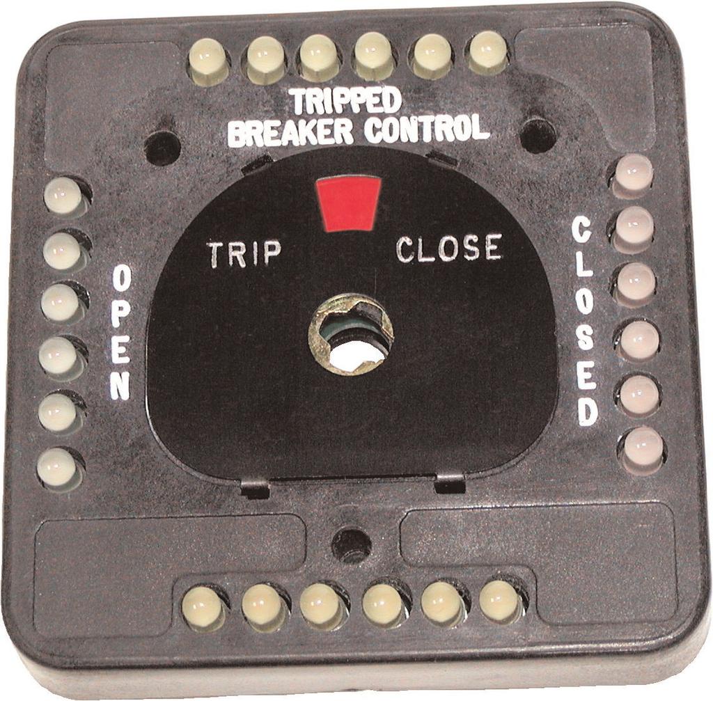
14 INSTRUMENT AND CONTRC ONTROL OL LIGHTED ESCUTCHEON PLATES OPERATION - 4 ROWS OF LEDS: Style 1, Standard Light Configuration When the handle is turned to the position, The flag shows red and the red lights are turned on by an auxiliary switch contact in the circuit breaker. If there is a fault and the circuit breaker trips, an auxiliary switch contact (bell circuit) in the Circuit breaker will close and the yellow lights flash - see typical circuit on page 14. When the handle is turned to the position, the flag shows green and the green lights are turned MATERIALS LIST: All lighted flag assemblies include the following- Escutcheon plate with flag assembly. Pistol grip handel with #6-3 x 5/8 screw Wire connections are made with #6-3 x 3/9 slotted brass screws with lock washers. Switch mounting hardware, 3 ea #10-3 x 1 slotted truss head, black zinc plated screws. on by an auxiliary switch contact in the circuit breaker. Style, (Reversed light Configuration) is selected, the above operation will apply but exchange red to green and green to red. Notes: 1. Panel Mounting. Jumper may be added to terminals D, E and/or F for OPERATION - ROWS OF LEDS: Style 1, Standard Light Configuration When the handle is turned to the position, the flag shows red and lights are turn on by an auxiliary switch contact in the circuit breaker. When the handle is turned common circuit connections for LEDs. 3. Voltage input is not polarity sensitive. to the position, the flag shows green and the green lights are turned on by an auxiliary switch contact in the circuit breaker. Style, (Reversed light Configuration) is selected,the above operation will apply but exchangered to green and green to red. ORDERING INSTRUCTIONS: Specify standard switch catalog number and add Lighted Escutcheon DASH NUMBER, ex: 95438D-L4R10. The Lighted Escutcheon requires a special handle and length mounting screws, so the DASH NUMBER must be included on the initial switch order. STYLE 1 STYLE REVERSED LIGHT CONFIGURATION LED VOLTAGE RATING ROWS OF LEDS SERIES 95 DASH # LED VOLTAGE RATING ROWS OF LEDS SERIES 95 DASH # 10 VAC 50/60 HZ or 15VDC -LR10 10 VAC 50/60 HZ or 15VDC -LR10R 40 VAC 50/60 HZ or 50VDC -LR40 40 VAC 50/60 HZ or 50VDC -LR40R 48VDC -LR48 48VDC -LR48R 10 VAC 50/60 HZ or 15VDC 4 -L4R10 10 VAC 50/60 HZ or 15VDC 4 -L4R10R 40 VAC 50/60 HZ or 50VDC 4 -L4R40 40 VAC 50/60 HZ or 50VDC 4 -L4R40R 48VDC 4 -L4R48 48VDC 4 -L4R48R INDICATION COLOR TERMINAL DESIGNATIONS DISPLAY INDICATION COLOR TERMINAL DESIGNATIONS DISPLAY OPEN GREEN A & D STEADY D RED B & E STEADY *PED YELLOW C & F FLASHING OPEN RED A & D STEADY D GREEN B & E STEADY *PED YELLOW C & F FLASHING Patented Feature: Leds are removable. If any Led fails and it is removed all others in the row remain lit. 13
15 INSTRUMENT AND CONTRC ONTROL OL LIGHTED ESCUTCHEON PLATES REAR VIEW QTY PART # COLOR 6 LED MV6351 YELLOW 6 LED MV6451 GREEN 6 LED MV6951 RED Notes: 1. LEDS are removable and inserted by the use of needle nose pliers. Polarity should be observed during installation. 3. Molded escutcheon panel LED ports are polarized. DRILL PATTERN ESCUTCHEON ASSEMBLY FRONT COVER WITH FLAG ROWS OF LEDS PART# 179C48 4 ROWS OF LEDS PART# 179C4867 CUSTOMER PANEL DECKS SERIES 95 ASSEMBLY STANDARD OUTLINE, NOT MODEL SPECIFIC MOLDED PISTOL GRIP HANDLE PART# 179B0856 PROTRUSION OF LEDS WHEN FULLY ASSEMBLED 14

16 g Instrument Transformers, Inc. CCS-SERIES95 1/06 Rev.
Bussmann series Quik-Spec Power Module Switch elevator disconnect
 Supersedes January 2016 Agency information UL 98 enclosed and dead-front switch - Guide WIAX, WIAX7 (Canada), File E182262 culus, NEMA 1, UL 50, Listed enclosure cul per Canadian Standards C22.2, No. 0-M91-CAN/
HKH Series. HAZCON Controls for Harsh and Hazardous Environments
 HKH Series HAZCON Controls for Harsh and Hazardous Environments Z A H LO C NON-METALLIC DIN RAIL MOUNT Component Mounting Rail Optional Customer I.D. Nameplate Optional Legend Plate Explosion Protective
Caterpillar 1500kW XQ1500
 Caterpillar 1500kW XQ1500 #4375 Diesel 480V EPA Tier 2 www.globalpwr.com Generator Features 2007 Caterpillar 1500 kw XQ1500 Diesel Generator. This XQ package features a sound attenuated enclosure, CAT
Data Bulletin. Ground-Censor Ground-Fault Protection System Type GC Class 931
 Data Bulletin 0931DB0101 July 2001 Cedar Rapids, IA, USA Ground-Censor Ground-Fault Protection System Type GC Class 931 09313063 GT Sensor Shunt Trip of Circuit Interrupter Window Area for Conductors GC
Electropneumatic Timing Relays Series 7000 Industrial
 DESIGN FEATURES Available in On-Delay, True Off-Delay, and On/Off-Delay. Timing from 0.1 seconds to 60 minutes, fully calibrated in linear increments. Oversize time-calibrated adjustment knobs, serrated
7000 series. Industrial Electropneumatic Timing Relay AGASTAT. Design Features. On-delay model 7012 (delay on pickup) Design & Construction
 Design & Construction") 7000 series Industrial Electropneumatic Timing Relay File E15631 File LR29186 Note:7032 types and certain models with accessories are not agency approved. Users should thoroughly review the technical data
7000 series Industrial Electropneumatic Timing Relay File E15631 File LR29186 Note:7032 types and certain models with accessories are not agency approved. Users should thoroughly review the technical data
XQ2000 SOUND ATTENUATED POWER MODULE
 XQ2000 SOUND ATTENUATED POWER MODULE 60 Hz FEATURES EMISSIONS EPA and CARB Emissions Certified for non-road mobile applications. CAT DIESEL GENERATOR SETS Factory designed, certified prototype tested with
Horizontal Circuit Switchers
 > Transformer Protection > CIRCUIT SWITCHERS C A T A L O G B U L L E T I N General Application Southern States Types CSH and CSH-B Horizontal Circuit Switchers provide an economical, versatile, space saving
Controls and Instruments
 CHAPTER 9 Controls and Instruments A complex set of controls and instruments monitors the operation of an electric generator set. Equipment operators must understand what these controls and instruments
Horizontal Circuit Switchers
 > Transformer Protection > CIRCUIT SWITCHERS C A T A L O G B U L L E T I N General Application Southern States Types CSH and CSH-B Horizontal Circuit Switchers provide an economical, versatile, space saving
JAE Series. Magnetic Circuit Protectors. Introduction Poles Configurations Operating Characteristics Delay Curves Decision Tables
 JAE Series Magnetic Circuit Protectors Introduction Poles Configurations Operating Characteristics Delay Curves Decision Tables 205 207 211 213 216 217 JAE/JRE/JLE Series Hydraulic Magnetic Circuit Protectors
Electrical Wiring Practices
 Chapter 2 Electrical Wiring Practices and Diagrams MElec-Ch2-1 Overview Safety Standards Wiring Considerations Wire Terminations Coaxial Cable Wiring Installations Wiring Diagrams MElec-Ch2-2 Safety Lethal
MULTI 9 System Catalog IEC Rated C60N/H/L Circuit Breakers
 IEC Rated C60N/H/L Circuit Breakers Standard Features Fast Closing Allows increased withstand to the high inrush currents of some loads Trip-free mechanism: Contacts cannot be held in the on position when
Table Line and Load Terminals. Terminal Body Material. Wire Type. Aluminum Copper Aluminum. English English English.
 -174 Series C Molded Case Circuit s July 7 Molded Case Switches Refer to Eaton for UL listed, series tested Molded Case Switch application data. Table -278. Molded Case Switches Cont. Amp Rating at 40
DIM. A (+ 0,05 0,51) .437 ±.020 (11,10 ± 0,51) DIM. F ±.015 (0,38) INTEGRAL ASSEMBLY NUT, DO NOT REMOVE
 .437 ±.020 (11,10 ± 0,51) DIM. F ±.015 (0,38) INTEGRAL ASSEMBLY NUT, DO NOT REMOVE") Multi-Deck SERIES,, and " Diameter, Amp, Standard, Military SR0 FEATURES Rugged Construction Insures Switch Operation for the Life of Your Equipment Many Circuitry Options MIL Qualified Versions MIL-S-/0
Multi-Deck SERIES,, and " Diameter, Amp, Standard, Military SR0 FEATURES Rugged Construction Insures Switch Operation for the Life of Your Equipment Many Circuitry Options MIL Qualified Versions MIL-S-/0
F-Series. Circuit Breaker
 F-Series Circuit Breaker The F-Series hydraulic/magnetic high amperage circuit breakers are designed to handle high current applications in extremely hot and/or cold locations. Due to its timeproven hydraulic/magnetic
Standard Grade Power Module
 Standard Grade Power Module Using Cat Diesel Engine Generator Sets FEATURES CAT DIESEL GENERATOR SETS Factory designed, certified prototype tested with torsional analysis. Production tested and delivered
F-Series. Circuit Breaker
 F-Series Circuit Breaker The F-Series hydraulic/magnetic high amperage circuit breakers are designed to handle high current applications in extremely hot and/or cold locations. Due to its timeproven hydraulic/magnetic
Application Engineering
 Application Engineering February, 2009 Copeland Digital Compressor Controller Introduction The Digital Compressor Controller is the electronics interface between the Copeland Scroll Digital Compressor
Allen-Bradley HP Inverting Fault Circuit Breaker Kit
 Allen-Bradley 1397 400-600HP Inverting Fault Circuit Breaker Kit Cat. Nos. 1397-IFB600 What This Option Provides This option is intended to be applied to regenerative 1397 drives with high inertia loads.
A system fault contribution of 750 mva shall be used when determining the required interrupting rating for unit substation equipment.
 General Unit substations shall be 500 kva minimum, 1500 kva maximum unless approved otherwise by the University. For the required configuration of University substations see Standard Electrical Detail
ENGINE GOVERNING SYSTEMS LSM672 LOAD SHARING MODULE. GOVERNORS AMERICA CORP. 720 Silver Street Agawam, MA , USA MEMBER
 ENGINE GOVERNING SYSTEMS LSM672 LOAD SHARING MODULE MEMBER GOVERNORS AMERICA CORP. 720 Silver Street Agawam, MA 01001-2907, USA LSM672 LOAD SHARING MODULE PRODUCT TECHNICAL INFORMATION PTI 4000 AUGUST
IEC Utilization Categories (Explanation)
") IEC Utilization Categories (Explanation) IEC Utilization Categories Voltage Category Typical Applications A.C. A.C. and D.C. D.C. AC AC AC AC ACa ACb AC6a AC6b AC7a AC7b AC8a AC8b AC AC AC AC AC AC AC
IEC Utilization Categories (Explanation) IEC Utilization Categories Voltage Category Typical Applications A.C. A.C. and D.C. D.C. AC AC AC AC ACa ACb AC6a AC6b AC7a AC7b AC8a AC8b AC AC AC AC AC AC AC
Application Engineering
 Application Engineering March 2011 Copeland Digital Compressor Controller Introduction The Digital Compressor Controller is the electronics interface between the Copeland Scroll Digital compressor or the
RCS1000 Data Sheet. RCS1000 Series Controllable Circuit Breaker Panel
 RCS000 Series Controllable Circuit Breaker Panel RCS000 Data Sheet Overview The RCS000 Series Controllable Circuit Breaker Panels combines the benefi ts of traditional relay based load control and the
Basics of Control Components
 Basics of Control Components Table of Contents Introduction...2 Electrical Symbols...6 Line Diagrams...16 Overload Protection...22 Overload Relays...26 Manual Control...35 Magnetic Contactors and Starters...41
Instruction Sheet for Powertite Plug, Connector and Receptacle
 330087 Instruction Sheet for Powertite Plug, Connector and Receptacle Powertite 200 Amp Pin & Sleeve Receptacles, Cable Connectors and Plugs: NEMA 4X. 600 Volt AC, 250 Volt DC. Wire Recess Diameter:.687.
Type MTS Miniature Test Switches
 Type MTS Miniature Test Switches o o o o Compact and versatile Front- and back-connected styles Safe, durable, rugged and reliable Recognized by CUL & UL DESCRIPTION In many panelboard, switchgear, metering,
209 Series. Magnetic Circuit Protectors
 29 Series Magnetic Circuit Protectors Introduction 249 Power Selector System Multi-Pole Configurations Operating Characteristics Delay Curves Specifications Decision Tables 73 75 77 79 8 82 85 87 29/29/229/249/279
Control Relays Overview
 Control Relays Overview DESIGN FEATURES Among the advances Agastat Control Relays offer over existing designs is a unique contact operating mechanism. An articulated arm assembly amplifies the movement
MODEL 422 Submersible Pump Controller
 MODEL 422 Submersible Pump Controller Monitors True Motor Power (volts x current x power factor) Detects Motor Overload or Underload Operates on 120 or 240VAC, Single-phase or 3-phase Built-in Trip and
Table Types LD, HLD and LDC Thermal-Magnetic Circuit Breakers with Interchangeable Trip Units
 -1 1 Amperes July 07 Product Selection Table -191. s, H and C Thermal-Magnetic Circuit s with Interchangeable Trip Units Maximum Continuous Ampere at 40 C 2-Pole 0 0 3-Pole 0 0 4-Pole 0 0 Magnetic trip
Parts Manual. Transfer Switch. OTPCB (Spec A) 150/225/260 Amps. English Original Instructions (Issue 4)
 150/225/260 Amps. English Original Instructions (Issue 4)") Parts Manual Transfer Switch 50/225/260 Amps OTPCB (Spec A) English Original Instructions -203 962 0228 (Issue ) This catalog covers models produced under the Cummins /Onan and Cummins Power Generation
Parts Manual Transfer Switch 50/225/260 Amps OTPCB (Spec A) English Original Instructions -203 962 0228 (Issue ) This catalog covers models produced under the Cummins /Onan and Cummins Power Generation
BENEFITS 782 STANDARD PART NUMBERS FEATURES 782 XDX M4L- 120A ORDERING CODE DPDT 10 AMP & 4PDT 3 & 5 AMP MINIATURE POWER RELAY FLAG INDICATOR:
 SERIES 782XBX/XDX DPDT 10 AMP & 4PDT 3 & 5 AMP MINIATURE POWER RELAY FEATURES FLAG INDICATOR: L.E.D. STATUS LAMP: PUSH BUTTON: LOCK-DOWN DOOR: FINGER-GRIP COVER: I.D. TAG/WRITE LABEL: COVER ADAPTERS: BENEFITS
Non-fusible. Non-fusible disconnect switches 16A 3150A, 600VAC A, 1000VDC. International acceptance. Disconnect switches.
 disconnect 16A 31A, 0VAC 200-0A, 1000VDC Disconnect Disconnect ABB SwitchLine includes 16 different amperage sizes from 16A to 31A. The basic construction provides flexibility, safety, and high performance
Parts Manual. Transfer Switch. OTPCC (Spec A) 300/400/600 Amps. English Original Instructions (Issue 4)
 300/400/600 Amps. English Original Instructions (Issue 4)") Parts Manual Transfer Switch 00/00/600 Amps OTPCC (Spec A) English Original Instructions -20 962 0229 (Issue ) This catalog covers models produced under the Cummins /Onan and Cummins Power Generation brand
Parts Manual Transfer Switch 00/00/600 Amps OTPCC (Spec A) English Original Instructions -20 962 0229 (Issue ) This catalog covers models produced under the Cummins /Onan and Cummins Power Generation brand
HOW TO ORDER SPECIFY AS SHOWN BELOW EXAMPLE #1
 MERCURY TO METAL CONTACTORS AND RELAYS GLASS SEAL GUIDE RETAINER TEFLON GUIDE MAGNETIC SLEEVE BOBBIN TERMINAL WELD RING CERAMIC INSULATOR ELECTRODE METAL CAP DESCRIPTION MERCURY TO METAL CONTACTOR: The
Installation and Maintenance Instructions. World Leader in Modular Torque Limiters. PTM-4 Load Monitor
 World Leader in Modular Torque Limiters Installation and Maintenance Instructions PTM-4 Load Monitor 1304 Twin Oaks Street Wichita Falls, Texas 76302 (940) 723-7800 Fax: (940) 723-7888 E-mail: sales@brunelcorp.com
PD-Series Ground Fault Circuit Protection
 PD-Series Ground Fault Circuit Protection SmartGuard is an equipment ground fault protection device that functions as a standard high-quality Carling hydraulic/ magnetic circuit breaker, offering customized
Fuseholders PAGE. Fuseholders.
 PAGE International Shock-Safe (Panel Mount).......................................................................... 467-468 Flip-Top Shock-Safe (Panel Mount)..................................................................................
MODEL ELC-12/40-CVM-D BATTERY CHARGER
 NATIONAL RAILWAY SUPPLY MODEL ELC-12/40-CVM-D BATTERY CHARGER Installing, Operating and Service Instructions for the ELC-12/40-CVM-D Solid State Charger PLEASE SAVE THESE IMPORTANT SAFETY AND OPERATING
NEMA 1, NEMA 4X and Chassis Mount Adjustable Speed Controls for DC Motors
 Made in the U.S.A. NEMA 1, NEMA 4X and Chassis Mount Adjustable Speed Controls for DC Motors Nema Enclosed DC Control Specifications Catalog Number BC140 or Features BC138 BC139 BC140-FBR BC154 BC160 BCWD140
3. Coils shall be of molded construction
 .7-4 Motor Starters & Contactors Low Voltage Enclosures General Non-Combination Starters January 00 Sheet 8 0 7 8 9 4 Non-Combination Starters Maximum hp, Volts Typical Non-Combination Starter Application
AP/UP, AP/MIL Series Magnetic Circuit Protectors
 AP/UP, AP/MIL AP/UP, AP/MIL Series Magnetic Circuit Protectors Introduction 68 Single Pole 69 Multi-Pole 70 Configurations 72 Operating Characteristics 73 Delay Curves 74 Specifications 75 Decision Tables
PB-Series. GFCI/ELCI & Panel Seal
 PB-Series GFCI/ELCI & Panel Seal The PB-Series utilizes the hydraulic magnetic principle which provides precise operation and performance even when exposed to extremely hot and/or cold application environments.
GJL 100 A Molded Case Circuit Breaker GJL 75 A Motor Circuit Protector
 GJL 100 A Molded Case Circuit Breaker GJL 75 A Motor Circuit Protector Catalog 0500CT9702R409 2009 Class 525/580 CONTENTS Description............................................. Page General Characteristics...................................
Manual motor protectors Type MS116 Type MS325 Type MS45X Type MS49X
 Manual motor protectors Type MS116 Type MS32 Type MS4X Type MS49X Manual motor protectors MS116 MS32 MS4X MS49X Description Type MS116 Suitable for use with 3-phase motors up to 10 HP @ 480V UL ed and
Table of Contents. HCC Contactor Nomenclature
 Table of Contents HC HCC SERIES: Definite Purpose Contactors... Page 1 Auxiliary Switches & Termination Drawings HCC SERIES: 1 & Pole Definite Purpose Contactors... Page 0 HCC SERIES: & Pole Definite Purpose
Switches. SERIES FEATURE ACTUATION MAX RATING SEAL RATING MOUNTING CIRCUITRY 115VAC, 28VDC)
") SWITCH SELECTION GUIDE Toggle Switches SERIES FEATURE ACTUATION MAX RATING SEAL RATING MOUNTING CIRCUITRY (Resistive @ 115VAC, 28VDC) T1 2 or 3 Position, Momentary, 8A MIL-PRF-83731 15/32" or 1/4" dia.
SWITCH SELECTION GUIDE Toggle Switches SERIES FEATURE ACTUATION MAX RATING SEAL RATING MOUNTING CIRCUITRY (Resistive @ 115VAC, 28VDC) T1 2 or 3 Position, Momentary, 8A MIL-PRF-83731 15/32" or 1/4" dia.
G-Series. Circuit Breaker.
 -Series Circuit Breaker Carling Technologies -Series hydraulic/magnetic circuit breakers offer the highest quality solution to your circuit protection requirements. The -Series is designed to sense over-current
5000 SERIES POWER SUPPLY/CHARGERS INSTALLATION GUIDE
 5000 SERIES POWER SUPPLY/CHARGERS INSTALLATION GUIDE MODEL# 505 ( AMP @ VDC OR 4VDC) MODEL# 5500 ( AMP @ VDC OR AMPS @ 4VDC) MODEL# 5600- (0 AMPS @ VDC) MODEL# 5600-4 (5 AMPS @ 4VDC) IMPORTANT SAFETY INSTRUCTIONS
Bulletin 109 IEC Non-Reversing Starters. Product Overview/Product Selection. Table of Contents
 Bulletin IEC Non-Reversing Starters Product Overview/Product Selection Cat. No. -CABAF--R-P IP (Type ) Metal Enclosure with Lift-off Cover Bulletin IEC Non-Reversing Starters Impact-resistant molded enclosures
Open & enclosed. Spec Tech Industrial 203 Vest Ave. Valley Park, MO Phone: 888 SPECTECH. Reduced voltage starters. Overload relay protection
 Reduced voltage starters Open & enclosed Reduced voltage starters Description Compact, space saving design 8 starter frame sizes, A16 to A750 Maximum U.L. horsepower ratings Mechanically interlocking as
www. ElectricalPartManuals. com Systems Pow-R Breaker Transfer Switches Technical Data Page 1
 Cl November 1984 New Information Mailed to: E, D, C/29-900A Westinghouse Electric Corporation Distribution and Protection Business Unit Commercial Division - Assemblies London, KY 407 41 Technical Data
SECTION MOTOR CONTROL
 SECTION 26 24 19 MOTOR CONTROL PART 1 - GENERAL 1.1 SECTION INCLUDES A. Manual motor starters B. Magnetic motor starters C. Combination magnetic motor starters D. Solid-state reduced voltage motor starters
Kulka Military Class (A-A-59125)/(MIL-T-55164)
/(MIL-T-55164)") Kulka Military Class (A-A-59125)/(MIL-T-55164) Military Class: Closed Back These military blocks feature molded-in terminals in an improved Kulka design for greater strength and flexibility. The mounting
Kulka Military Class (A-A-59125)/(MIL-T-55164) Military Class: Closed Back These military blocks feature molded-in terminals in an improved Kulka design for greater strength and flexibility. The mounting
the Interactive Catalog
 Interactive Catalog Supplements Catalog PDFs If you need detailed product information, or help choosing the right product for your application, see our Interactive Catalog Use the Interactive Catalog to
GE Industrial Systems. General Purpose Plug-in Relays. Catalog
 GE Industrial Systems General Purpose Plug-in Relays Catalog GE General Purpose Plug-in Relays GE Industrial Systems new CR20 series comprises a comprehensive general purpose plug-in relay family. Often
Commerical Comfort System (CCS) Variable Air Volume (VAV) Zone Pressure Independent Damper Controller
 Variable Air Volume (VAV) Zone Pressure Independent Damper Controller") LC-ZEC200-xxxx Commerical Comfort System (CCS) Variable Air Volume (VAV) Zone Pressure Independent Damper Controller Description The CCS Variable Air Volume (VAV) Zone Pressure Independent Damper Controllers
LC-ZEC200-xxxx Commerical Comfort System (CCS) Variable Air Volume (VAV) Zone Pressure Independent Damper Controller Description The CCS Variable Air Volume (VAV) Zone Pressure Independent Damper Controllers
User s Manual. ACS550-CC Packaged Drive with Bypass Supplement for ACS550-01/U1 Drives User s Manual
 User s Manual ACS550-CC Packaged Drive with Bypass Supplement for ACS550-01/U1 Drives User s Manual ii ACS550-CC Packaged Drive with Bypass ACS550 Drive Manuals GENERAL MANUALS ACS550-01/U1 Drives User's
ELECTRIC SCHEMATICS LS1 LS2. "1532ES / 1932ES" Service & Parts Manual - ANSI Specifications March 2008 Page 5-9 ART_2236 ART_2243
 ELECTRIC SCHEMATICS NOTES: (Unless otherwise specified). Switch S BASE/PLATFORM makes contact from the CENTER to the LEFT position when placed in BASE.. Switch S UP/DOWN makes contact from the CENTER to
Protection Equipment
 Protection Equipment Price Groups 101, 102, 121, 131, 143 /2 Introduction Motor Starter Protectors/ Circuit Breakers SIRIUS 3RV2 Motor Starter Protectors up to 40 A new /7 General data /13 For motor protection
ICT TRANSFORMERS. Industrial Control Transformers provide a low and safe control voltage for the operation of many electromagnetic devices
 ICT TRANSFORMERS Industrial Control Transformers provide a low and safe control voltage for the operation of many electromagnetic devices TA SERIES INDUSTRIAL CONTROL TRANSFORMER Industrial control transformers
Rotary Cam Switches. Rotary Cam Switches
 Rotary Cam es Series... 2 Handle Assemblies... 8 Accessories... 12 Circuit Diagrams, Technical Information & Dimensions (Online)... 13 Series R-Line Rotary Cam es... 24 Handles and Accessories... 27 Circuit
User s Manual. ACS550-CC Packaged Drive with Bypass Supplement for ACS550-01/U1 Drives User s Manual
 User s Manual ACS550-CC Packaged Drive with Bypass Supplement for ACS550-01/U1 Drives User s Manual ii ACS550-CC Packaged Drive with Bypass ACS550 Drive Manuals GENERAL MANUALS ACS550-01/U1 Drives User's
DIN Rail UPS DC UPS/Battery Detection System Model: BDS-DIN-UPS Installation/Operation Manual
 DIN Rail UPS DC UPS/Battery Detection System Model: BDS-DIN-UPS 24-10 Installation/Operation Manual Table of Contents Section Page Section Page Quick Start 2 1) General Information 4 Materials Provided
Temperature Control Panel Wiring Diagram Model: ISPA-120-1P-15A
 Temperature Control Panel Wiring Diagram Model: ISPA-0-P-5A Shift Controls, Inc. Installed Options: TC Jack Panel Connector Interlock Relay, RLY- 5A Power Cord www.shift-controls.com support@shift-controls.com
Suitable for use as: OSHA Lockout/Tagout. disconnects. Safety switches Load break switches Isolators
 SafeLine Compact, heavy duty disconnect 6A 200A 30A 200A Fusible Disconnect SafeLine enclosed disconnect are designed to meet customer requirements in terms of safety, ease of installation, space savings
Electronic Circuit Breaker ESS20-0..
 Electronic Circuit Breaker ES-0.. Description Electronic circuit breaker type ES-0.. is designed to ensure selective disconnection of individual loads in systems which are powered by a DC 4 V switch-mode
Low Voltage Automatic Transfer Switch Systems
 Suitable for Emergency, Peak and Prime Power System Applications Low Voltage Automatic Transfer Switch Systems THE POWER AUTHORITY THE POWER AUTHORITY ASCO s experience and commitment to excellence in
Training & Didactic Systems. Fundamentals of Electrical Engineering
 Training & Didactic Systems Fundamentals of Electrical Engineering Catalog WA1E/01 Table of Contents Page Our Service, Our Customers and fields of technology 2 Introduction 4 Instruction modules measuring
J1 Plug Pin Identification
 D5 D D D D5 D ART_ J D D0 R R R R TB 0 D D D D D D J Plug Pin Identification PIN # WIRE # SIGNAL FUNCTION 0 INPUT Drive Reverse INPUT Drive Forward OUTPUT Brake, Decel Valve signal INPUT Steer Left 5 OUTPUT
PowerPact Circuit Breakers for Control Panel Disconnects Class 0611
 Data Bulletin 0611DB0402 R04/16 05/2016 Replaces 0611DB0401 R11/11 PowerPact Circuit Breakers for Control Panel Disconnects Class 0611 Retain for future use. Introduction Certifications The electrical
Single Pole Circuit Protectors 55. Multi-Pole Circuit Protectors 56. Configurations 58. Operating Characteristics 59.
 Single Pole Circuit Protectors 55 Multi-Pole Circuit Protectors 56 Configurations 58 Operating Characteristics 59 Delay Curves 60 Specifications 61 Decision Tables 62 SINGLE POLE CIRCUIT PROTECTORS The
Controls / Terminal Blocks Controls. CXS Series Special Cam Switches (IEC 947-3) Special Cam Switches CXS Series Features
 Special Cam Switches CXS Series Features") F Controls / Terminal Blocks Controls CXS Series Special Cam Switches (IEC 947-3) IEC 947-3 Special Cam Switches CXS Series Features SAMWHA CXS Series Cam Switches are used for non hazardous area. Functionally
F Controls / Terminal Blocks Controls CXS Series Special Cam Switches (IEC 947-3) IEC 947-3 Special Cam Switches CXS Series Features SAMWHA CXS Series Cam Switches are used for non hazardous area. Functionally
Section. Circuit Breakers Selection Guide...N-2. NRA Series...N-3. NRBM Series...N-13. NRC Series...
 Section Selection Guide...-2 RA Series...-3 RBM Series...-3 RC Series...-20 General Instructions...-29 Internal Circuit Overview...-29 for more information on this product family visit www.idec.com/circuitbreaker
DIN Rail UPS Model: DIN-UPS Installation/Operation Manual
 DIN Rail UPS Model: DIN-UPS 24-10 Installation/Operation Manual Table of Contents Section Page Section Page Quick Start 2 1) General Information 4 Materials Provided 4 Optional Equipment 4 2) Safety Information
Distinctive Characteristics
 Distinctive Characteristics Various cap styles and colors to meet differing application needs. Bright, full face illumination to distinctively indicate status. Rear panel threaded mounting or snap-in mounter
Demand Switch NEFA20 Plus. Installation Guide. Please read this entire guide before beginning the installation!
 Demand Switch NEFA20 Plus Installation Guide Please read this entire guide before beginning the installation! Supplied Parts Protective Covers DIN Mounting Rail NEFA20 Plus Mounting Rail Spacer Warning
CIT SWITCHTM ANT SPECIFICATIONS
 Wide variety of applications from consumer electronics to commercial Standard epoxy sealed terminations Gold contacts available for low power applications Available support brackets for greater stability
CURRENT TRANSFORMER MODEL N. SS BAND SECURES BRACKET (view of screw clamp band omitted for clarity) 0.25 x 0.50 SLOT (2 PLACES)
 0.25 x 0.50 SLOT (2 PLACES)") MODEL N 4." I.D. PAGE No 1-30 TERMINAL OPTION LEAD WIRE OPTION 6.75 SS BAND SECURES BRACKET (view of screw clamp band omitted for clarity) 0.75 1.36 1.16 5.75 7.00 0. x 0.50 SLOT (2 PLACES) UL 1015 #16
MODEL N 4." I.D. PAGE No 1-30 TERMINAL OPTION LEAD WIRE OPTION 6.75 SS BAND SECURES BRACKET (view of screw clamp band omitted for clarity) 0.75 1.36 1.16 5.75 7.00 0. x 0.50 SLOT (2 PLACES) UL 1015 #16
Coil Data Nominal Current MA Nominal VA Sealed Single Pole Normally Open (SPNO) White Rodgers Q
 White Rodgers Q") 14/03/08 A136 Relay - General Purpose 90-293Q Enclosed fan relays used for switching single or two speed fan motors, solenoids, relays, resistive loads, heating and cooling applications and general purpose
14/03/08 A136 Relay - General Purpose 90-293Q Enclosed fan relays used for switching single or two speed fan motors, solenoids, relays, resistive loads, heating and cooling applications and general purpose
LB LOAD BANK MANUAL CONTAINS OPERATING INSTRUCTIONS PARTS LIST WIRING DIAGRAMS SERVICE INSTRUCTIONS
 LB-60-30 LOAD BANK MANUAL CONTAINS OPERATING INSTRUCTIONS PARTS LIST WIRING DIAGRAMS SERVICE INSTRUCTIONS 4031 W Kiehnau Ave Milwaukee, WI 53209 CAUTION THIS LOAD BANK IS DESIGNED FOR THE TESTING AND SERVICING
 No-barrier design Self-extinguishing materials Front-connected, back-connected and flush-mounted styles Blades operate independently or can be ganged together Recognized by UL and cul STATES Type have
S200 UL 489 Series. Miniature circuit breakers S200. Features. Description
 UL 489 Series UL 489 Series Description The Series miniature circuit breaker offers a compact solution for protection requirements. The U AND UP devices are UL 489 tested limiting and DIN rail mounted.
File E31519 Project 10CA February 4, 2011 REPORT MAGNETIC MOTOR CONTROLLERS. Siemens AG Amberg, Germany
 File E31519 Project 10CA65262 February 4, 2011 REPORT on MAGNETIC MOTOR CONTROLLERS Siemens AG Amberg, Germany Copyright 2011 Underwriters Laboratories Inc. Underwriters Laboratories Inc. authorizes the
Features. Emergency Stop Switch A22E. Install in 22-dia. or 25-dia. Panel Cutout. Safety Lock Mechanism to Prevent Misuse.
 Switch A22E Install in 22-dia. or 25-dia. Panel Cutout Direct opening mechanism to open the circuit when the contact welds. Safety lock mechanism prevents operating errors. Easy mounting and removal of
Bussmann series Quik-Spec Coordination Panelboard
 Quik-Spec electrical gear 12 Contents Bussmann series Quik-Spec Coordination Panelboard Section page Description Quik-Spec Coordination Panelboards Up to 400 A 2 600 to 1200 A 3 Quik-Spec elevator disconnects
Safety Interlock Switches
 Safety Interlock Switches ATK ATK Safety Key Selector Switch Key-type selector switch with direct opening mechanism Selector Switch for secure equipment activation during maintenance 0 types of exclusive
I-BFV.KIT Butterfly Valve Gear Operator Replacement
 SERIES 5, 05,, and 0C WARNING Read and understand all instructions before attempting to install, remove, adjust, or maintain any Victaulic piping products. Depressurize and drain the piping system before
General Purpose Relay
 General Purpose Relay Designed small, 2- and 3-pole types break 5 A loads and 4-pole type, 3 A load High reliability, long life Ultra-high sensitivity with quick response High vibration/shock resistance
G-Series DIN-RAIL CIRCUIT BREAKER
 G-Series DIN-RAIL CIRCUIT BREAKER The G-Series hydraulic-magnetic circuit breaker insures maximum protection by integrating wiping contacts for longevity; a common trip linkage between poles; a unique
REQUIREMENTS FOR PARALLEL OPERATION FOR CUSTOMERS WITH GENERATION NOT EXCEEDING 50 kw
 REQUIREMENTS FOR PARALLEL OPERATION FOR CUSTOMERS WITH GENERATION NOT EXCEEDG 50 kw FOREWARD Requirements for Parallel Operations for Customers with Generation Not Exceeding 50 kw is intended to be used
SE-125 MANUAL GROUND-FAULT GROUND-CHECK MONITOR
 SE-125 MANUAL GROUND-FAULT GROUND-CHECK MONITOR FEBRUARY 14, 2001 REVISION 3 Publication: SE-125-M Document: S95-C125-00000 Printed in Canada. Copyright 2001 by Startco Engineering Ltd. All rights reserved.
Medium Voltage Metal-Enclosed Switches
 Medium Voltage Metal-Enclosed Switches Outdoor Medium Voltage Switch.1 Medium Voltage Switch MVS Product Description............................................. 2 Application Description..........................................
ACW Molded-Case Circuit Breaker UL 489 Listed
 Motors Automation Energy Transmission & Distribution Coatings Molded-Case Circuit Breaker UL 489 Listed Overview Introducing the WEG Series of Molded Case Circuit Breakers now available with UL489 certification.
Application guide. Tmax Link OEM UL 891 Switchboard Program
 Application guide Tmax Link OEM UL 891 Switchboard Program 04 Tmax Link Overview 04 Standards 04 UL File Extension Process Overview 05 Electrical Data 05 Technical Data 05 Ambient Conditions 08 Circuit
SE-3SCR-LM MANUAL MOTOR LOAD MANAGER
 3714 Kinnear Place Saskatoon, SK Canada S7P 0A6 Ph: (306) 373-5505 Fx: (306) 374-2245 www.littelfuse.com/relayscontrols SE-3SCR-LM MANUAL MOTOR LOAD MANAGER MARCH 5, 2013 REVISION 4 MOTOR LOAD MANAGER
University of Houston Master Construction Specifications Insert Project Name
 SECTION 26 13 13 MEDIUM VOLTAGE SWITCHGEAR PART 1 - GENERAL 1.1 RELATED DOCUMENTS: A. The Conditions of the Contract and applicable requirements of Divisions 0 and 1 and Section 26 00 01, Electrical General
Selection and Application Guide Supplement. WL UL Pole Circuit Breakers. usa.siemens.com/wlbreaker
 Selection and Application Guide Supplement WL UL1066 4-Pole Circuit Breakers usa.siemens.com/wlbreaker WL Power Circuit Breaker Table of Contents Ratings for UL 1066 (ANSI C37) Circuit Breakers Frame size