Low Voltage Automatic Transfer Switch Systems
|
|
|
- Geraldine Margery McKinney
- 6 years ago
- Views:
Transcription


1 Suitable for Emergency, Peak and Prime Power System Applications Low Voltage Automatic Transfer Switch Systems THE POWER AUTHORITY

2 THE POWER AUTHORITY ASCO s experience and commitment to excellence in designing and building Emergency Power Control Systems for any application has made us the premier manufacturing and service organization in the world. For over 100 years we have built upon a tradition of providing our customers a full range of high performance and quality products. ASCO s experience spans the history of the power control industry and since 1888 we have set the standard for the entire industry. Our reputation as the leader in emergency power control equipment speaks to the quality of our products and the dedication of our people. ASCO operates two modern facilities dedicated to manufacturing low and medium voltage power control systems. Located in Parsippany, New Jersey and Stockton, California, these manufacturing plants produce state-of-the-art power control systems for emergency or standby power generation, peak load shaving, prime power, parallel with utility, cogeneration, emergency load management and power distribution. These products are designed and manufactured to meet and exceed the demands of a growing global market. Our ongoing dedication to research & development and extensive testing have confirmed ASCO products as the industry standard. Since our beginnings this same dedication has established ASCO as the pioneering innovator in the emergency power control industry. This commitment continues to set ASCO apart as the company that stands at the threshold of new technologies and has resulted in a long list of industry firsts throughout the years. ASCO has always been committed to providing a full range of products with only one thing in mind... transferring power from an available source to a critical load. Telecommunications systems, data networks, industrial processes and critical installations demand proven emergency and standby power transfer solutions. As the worlds leader in emergency and standby power, ASCO products and systems safeguard your business... because we keep your power on. Fig. 1 Parsippany, New Jersey, USA Fig. 2 Stockton, California, USA Page 2
3 Automatic Transfer Systems Product Overview Content Page Service Entrance Rated Transfer System... 4 ATS Switchboard... 5 Two Source Automatic Transfer System... 6 Three Source ATS System... 7 Three Source Priority System... 8 Soft Transfer System... 9 Custom Applications For more information on ASCO Automatic Transfer Systems contact your nearest ASCO source at ASCO or visit our website at Page 3

4 Service Entrance Rated Transfer System ASCO service entrance rated transfer systems are designed for automatic switching of loads between the utility source and an alternate source of power. The transfer system also contains a disconnect device on the normal source, plus a disconnect link on the utility neutral, and a disconnect link between neutral and ground. If the utility source is Y connected, the voltage is greater than 250 volts phase to neutral and the system continuous current is greater than 1000 amperes, the utility disconnect device will be equipped with ground fault trip. Figure 3 shows a typical service entrance rated transfer system with a 1200 ampere automatic transfer switch and a 1200 ampere utility circuit breaker. Fig. 3 Service entrance rated transfer system. The utility disconnect device will be equipped with ground fault trip if the voltage between neutral and ground is greater than 250 volts, and the continuous current is greater than 1000 amperes. Ground Disconnect Link Utility Disconnect link for the utility neutral bus. Disconnect link between the neutral bus and the ground bus. Neutral Disconnect Link GFCT Utility CB Meets all NEC requirements for service entrance rating, and is labeled to UL 891 standards. Available up through 4000 amperes using ASCO 940, 962, 434, 436 and ASCO's new 7000 series automatic transfer switches. N Ø N Acc. 28 Emergency Ø ATS GFCT - Ground Fault Current Transformer ATS - Automatic Transfer Switch Page 4 Fig. 4 One line diagram of the service entrance rated transfer system shown in figure 3.

5 ATS Switchboards An automatic transfer switchboard is a switchboard containing two or more automatic transfer switches in a common line-up. The switchboard shown in figure 5 contains two ASCO 962, 2000 ampere, automatic transfer bypass-isolation switches with circuit breakers on the normal and load side of each switch. An ammeter and voltmeter are also located on the load side of each switch. Connects multiple automatic transfer switches together in a common switchboard. Optional normal and/or emergency circuit breakers for overcurrent protection. Optional distribution circuit breakers of the size and type to meet customer load requirements. Fig. 5 Automatic transfer switchboard. Optional instrument meters for normal, emergency, or load for local monitoring. Designs can be provided with a UL 891 Label containing up through a 10,000 ampere main bus. Utilizes ASCO 940, 962, 434, 436 and ASCO's new 7000 series automatic transfer switches. Source #1 Circuit Breaker V 43 ATS/BP #1 ATS/BP #2 43 V Circuit Breaker Source #2 A A Circuit Breaker Circuit Breaker V - Voltmeter A - Ammeter 43 - Selector Switch ATS/BP - Automatic Transfer and Bypass-Isolation Switch Fig. 6 One line diagram of the automatic transfer switchboard shown in figure 5. Page 5

6 Two Source Automatic Transfer System ASCO two-source systems are designed for automatic switching of loads between the utility source and an alternate source of power. Upon the loss of the utility power source, the system provides an automatic start signal to the alternate source of power. Once the alternate source has reached proper voltage and frequency, the system transfers the critical load from the utility source to the alternate power source. When normal power is restored the controls will retransfer the load to the utility and signal shutdown of the alternate power source after allowing a cooldown period. ASCO two-source systems include an automatic transfer switch, plus any or all of the following options; automatic engine starting controls, overcurrent protection for both emergency and normal sources, instrument meters, status annunciation, and audible alarm. The systems are designed to NEMA switchboard construction and are labeled to UL 891 standards. These systems can be designed for top cable entrance, bottom cable entrance or bus duct connections. The system shown in figure 7 contains a 1200 ampere closed transition automatic transfer switch with a 1200 ampere utility circuit breaker, multi-purpose meter, reverse power relay, and an alarm horn. Fig. 7 Two source system with main circuit breaker, protective relaying and and automatic transfer switch rated 1200 amperes. Normal, emergency, and/or load circuit breakers. Protective relaying (as required). Normal Source MM 32 Optional instrument meters for normal, emergency, or load for local monitoring. LOAD ATS Designs are based on NEMA and UL 891 standards. Engine Optional engine start control logic and/or load control logic. Designs available up to 4000 amperes utilizing ASCO 940, 962, 434, 436 and ASCO's new 7000 series automatic transfer switches. MM = Multi-Purpose Meter 32 = Reverse Power Relay ATS = Automatic Transfer Switch Fig. 8 One line diagram of the two source automatic transfer system shown in figure 7. Page 6

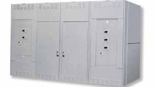
7 Three Source Automatic Transfer System ASCO three-source systems are similar to ASCO twosource systems except that a second alternate power source is added to back up the first if that power source fails. Upon the loss of the utility power source, the system provides all necessary controls to start both alternate power sources. The critical loads are automatically transferred to the first alternate power source that achieves acceptable voltage and frequency. The second alternate power source is then automatically shutdown after a time delay and cooldown period. If the first alternate power source fails, the second alternative power source will be automatically re-started and the load will be transferred from the first alternative power source to the second alternative power source. When the normal power is restored, the controls automatically retransfer the load to the utility power source. Figure 9 shows a three source automatic transfer system with two 940 automatic transfer switches and three distribution circuit breakers for feeding critical loads. Fig. 9 Three source automatic transfer system. Control logic for selecting between the alternative power sources. Normal, emergency, and/or load circuit breakers. Protective relaying (as required). Optional instrument meters for normal, emergency, or load for local monitoring. Designs are based on NEMA and UL 891 standards. Circuit Breakers NORMAL SOURCE ATS1 ATS2 Engine 1 Engine 2 Optional engine start control logic and/or load control logic. Designs available up to 4000 amperes utilizing ASCO 940, 962, 434, 436 and ASCO's new 7000 series automatic transfer switches. ATS = Automatic Transfer Switch Fig. 10 One line diagram of the three source automatic transfer system shown in figure 9. Page 7

8 Three Source Priority System Fig. 11 Three source priority system. ASCO three-source priority systems are similar to the ASCO three-source systems except they protect two critical loads rather than one critical load. Upon the loss of the utility power source, the system provides all necessary controls to start both alternative power sources. The most critical load is transferred to the first alternate power source that achieves acceptable voltage and frequency. The second most critical load is then transferred to the second alternate power source when it achieves acceptable voltage and frequency. If the alternate power source feeding the most critical load should fail, the most critical load would be transferred to the second alternate power source and the second most critical load would be shed. When the utility power source is restored, the system controls automatically retransfer the loads to the utility and both alternate power sources are run for a cooldown period and then shutdown. Figure 11 shows a three source priority system containing a priority selector transfer switch (ATS-2) and seven distribution circuit breakers. ATS-1 and ATS-2 are wall mounted automatic transfer switches and are not shown in this line-up. Priority selector transfer switch. Control logic for selecting between alternate power sources Normal, emergency, and/or load circuit breakers. Protective relaying (as required). Optional instrument meters for normal, emergency, or load for local monitoring. Designs are based on NEMA and UL 891 standards. Optional engine start control logic and/or load control logic. Designs available up through 4000 amperes utilizing ASCO 940, 962, 434, 436 and ASCO's new 7000 series automatic transfer switches. Page 8 NORMAL SOURCE ATS - 1 ATS - 3 No.1 No. 2 Critical Critical ATS - 2 Engine 1 Engine 2 ATS = Automatic Transfer Switch Fig. 12 One line diagram of the three source priority system shown in figure 11.


9 Soft Transfer System ASCO soft load closed transition transfer switches provide a make-beforebreak transfer of a building load from a utility power source to an alternate power source. This system automatically brings the engine generator into synchronism with the utility source, then gradually shifts the load from the utility to the engine generator with virtually no voltage or frequency fluctuations. Figure 13 shows a typical soft load transfer system containing an ASCO closed transition transfer switch. Open or closed transition transfer between normal and emergency. Emergency or peak shave mode of operation. Engine start control logic and load control logic. Available configurations include either an ASCO 434, 436 or ASCO s new 7000 Series closed transition transfer switches through 4000 amperes. The transfer system configuration can also accommodate power circuit breakers. Normal and emergency circuit breakers can be provided when using a transfer switch for overcurrent protection. Full manual paralleling operation (standard). Protective relaying (as required). Optional instrument meters for normal, emergency, or load for local monitoring. Designs are based on NEMA and UL 891 standards. Fig. 13 Soft load transfer system. Alternate Power Source Ground 400A Neutral 2000A 43 A STB Utility Power Source Phase 2000A KW STB 65* 90* Note: * Furnished by alternate power source supplier 43 SY 25C V F To 52G Shunt Trip CTTS ASCO Control Panel 86 KW 32R Watt XDCR STB Fig. 14 One line diagram of the soft load transfer system shown in figure 13. V 47N O/U 43 V - Voltmeter A - Ammeter F - Frequency Meter KW - Wattmeter Watt XDCR - Watt Transducer STB - Shorting Terminal Block 25C - Synch Check Relay 27/59 - Under/Over Voltage Relay 32R - Reverse Power Relay 47N - Phase Sequence Under Voltage Relay 65 - Governor (*) 81O/U - Over/Under Frequency Relay 90 - Voltage Regulator (*) CTTS - Closed Transition Transfer Switch SY - Synchroscope 43 - Phase Selector Switch 86 - Lockout Relay Page 9


10 Custom Applications Fig. 15 Selective load system. Selective System Selective load systems allow one load at a time to be operated when normal power fails. The system uses the minimum amount of auxiliary power for operation so the alternate power source can be sized for only one load at a time. The selective load system can be designed to handle any number of loads in any combination of sizes to suit the customers needs. The only interfacing between the ASCO selective load system and the load controls are power cables. The system can be used with any electrical load application where only one load out of a number of loads are to be operated from the alternate power source at one time. A typical application is with multiple banks of elevators when you want to enable only one elevator at a time to operate under emergency conditions. The system can be supplied with a separate control panel, which allows loads to be selected from a remote location. Figure 15 shows a typical selective load system with transfer switches for five loads. The control panel has a selector switch and position indication of each load. Transfer Switch with Distribution System Transfer switches can be provided with normal and emergency circuit breakers for overcurrent protection, plus any combination of distribution circuit breakers, bolted pressure switches, or fusible disconnect switches. Figure 16 shows a switchboard containing a circuit breaker on the normal source of the automatic transfer switch plus a distribution panelboard of molded case circuit breakers to protect critical downstream loads. The cubicle on the left end of the system provides monitoring and control of the distribution system. Fig. 16 Transfer switch with distribution. Page 10


11 Custom Applications Transfer Switch with Bottom Bus Risers Figure 17 shows a 4000 ampere transfer switch with bus risers for bottom entry bus duct on both the normal source and load connections. The emergency side of the transfer switch has lugs for cable connections from the top of the enclosure. This demonstrates our capability to meet custom service entry requirements. Fig. 17 Transfer switch with bottom bus riser. Transfer Switch in an Outdoor Enclosure Figure 18 shows a transfer switch with a fuse disconnect switch on the normal side. The switch is in a non-walk-in NEMA 3R outdoor enclosure. The outdoor enclosure is designed for front and rear entry only with three point catches on the doors as well as provisions for padlocking. Outdoor enclosures are available for all ASCO transfer switch products. Fig. 18 Transfer switch in an outdoor enclosure. Page 11
ASCO Low Voltage Automatic Transfer Switch Systems
 ASCO Low Voltage Automatic Transfer Switch Systems Suitable for Emergency, Peak and Prime Power System Applications ASCO s experience and commitment to excellence in designing and building Emergency Power
Mar H: SUPPLEMENTAL PARALLELING GEAR (16315-H)
") 2101 Commonwealth Blvd, Suite B Ann Arbor, MI 48105-5759 www.med.umich.edu/facilities/plan/ 263010-H: SUPPLEMENTAL PARALLELING GEAR (16315-H) Related Sections Basis Guideline: N/A For an explanation of
2101 Commonwealth Blvd, Suite B Ann Arbor, MI 48105-5759 www.med.umich.edu/facilities/plan/ 263010-H: SUPPLEMENTAL PARALLELING GEAR (16315-H) Related Sections Basis Guideline: N/A For an explanation of
Model ESV Uninterruptible Power System 1.5 KVA/KW KVA/KW Single Phase
 Model ESV Uninterruptible Power System 1.5 KVA/KW - 14.0 KVA/KW Single Phase 1.0 General General Specification This specification describes the features and design of an on-line, dual conversion, uninterruptible
CLIENT: PROJECT: PO#: ESTIMATOR:
 GENERATOR CONTROL DATA SHEET CLIENT: PROJECT: PO#: ESTIMATOR: PRIME MOVER FUEL: RPM: GOVERNOR SPEED ADJUST RHEOSTAT SUPPLIED WITH GOVERNOR: LOAD SHARING: REMOTE: PRIME MOVER PROTECTION LOW OIL PRESSURE
Optimizing Emergency Power Systems for Health Care Applications
 2018 Annual Conference Optimizing Emergency Power Systems for Health Care Applications aka: Using the latest code changes to improve system reliability and maybe even save some $$$... Overview Michigan
Industrial Generator Set Accessories. Standard Features. Line Circuit Breakers kw
 Industrial Generator Set Accessories Line Circuit Breakers 15-2500 kw Standard Features Single Circuit Breaker Kit with Neutral Bus Bar 15-300 kw Model Shown The line circuit breaker interrupts the generator
SECTION MOTOR CONTROL
 SECTION 26 24 19 MOTOR CONTROL PART 1 - GENERAL 1.1 SECTION INCLUDES A. Manual motor starters B. Magnetic motor starters C. Combination magnetic motor starters D. Solid-state reduced voltage motor starters
PARALLELING SWITCHGEAR
 ONBOARD VS TRADITIONAL IEEE Central Tennessee PARALLELING SWITCHGEAR Dustin Sperber Application Engineer Manager Nixon Power Services Objective for todays meeting: To examine the latest technology in paralleling
2018 Consultant s Handbook Division 26 Electrical 2413 Switchboards
 1 General 1.1 Switchboards shall be U.L. listed and labeled. 1.2 Each switchboard shall have its own main disconnecting means unless it is located in the same room as its source of origin. In most cases
A system fault contribution of 750 mva shall be used when determining the required interrupting rating for unit substation equipment.
 General Unit substations shall be 500 kva minimum, 1500 kva maximum unless approved otherwise by the University. For the required configuration of University substations see Standard Electrical Detail
Operator s Series 300 Generator Paralleling System
 Operator s Series 300 Manual Generator Paralleling System +Before reading please note the following: DANGER is used in this manual to warn of a hazardous situation which, if not avoided, will result in
Service Entrance Methods
 Service Section Typical switchboards consist of a service section, also referred to as the main section, and one or more distribution sections. The service section can be fed directly from the utility
Bolted contact switches. Pringle switches
 Bolted contact switches Pringle switches Eaton s Pringle bolted contact switches History Eaton s PringleT switches have helped pioneer the development of high-quality electrical products for commercial
SECTION LOW VOLTAGE DISTRIBUTION EQUIPMENT
 SECTION 16400 LOW VOLTAGE DISTRIBUTION EQUIPMENT A. General 1. The University does not accept Series-Rated equipment for power distribution switchboards, distribution panels and branch circuit panelboards.
SPECIAL SPECIFICATION 5066 Packaged Engine Generator System
 2004 Specifications CSJ 2121-04-072 SPECIAL SPECIFICATION 5066 Packaged Engine Generator System 1. Description. Furnish and install packaged engine generator system complete with transfer switch and service
Medium Voltage Standby non-paralleling Control GUIDE FORM SPECIFICATION
 Medium Voltage Standby non-paralleling Control 1. GENERAL GUIDE FORM SPECIFICATION A. The requirements of the contract, Division 1, and part 16 apply to work in this section. 1.01 SECTIONS INCLUDE A. Medium
Operator s Manual Series ACTS Automatic Closed Transition Transfer Switches 150 through 4000 amps A. Rating Label.
 Operator s Manual 7000 Series ACTS Automatic Closed Transition es 150 through 4000 amps TABLE OF CONTENTS section-page INSTALLATION... 1-1 Mounting and Line Connections... 1-1 Auxiliary Circuits and Harness...
DG SYNCHRONIZING &AMF PANEL
 A 80, Sector 80, Phase 2, Noida 201305, Utter Pradesh, India DG SYNCHRONIZING &AMF PANEL Clients Bharat Petroleum Corp.Ltd PROJECT- DG Synchronization panel with AMF function. Design BY:- Errection By
www. ElectricalPartManuals. com Systems Pow-R Breaker Transfer Switches Technical Data Page 1
 Cl November 1984 New Information Mailed to: E, D, C/29-900A Westinghouse Electric Corporation Distribution and Protection Business Unit Commercial Division - Assemblies London, KY 407 41 Technical Data
Caterpillar 1500kW XQ1500
 Caterpillar 1500kW XQ1500 #4375 Diesel 480V EPA Tier 2 www.globalpwr.com Generator Features 2007 Caterpillar 1500 kw XQ1500 Diesel Generator. This XQ package features a sound attenuated enclosure, CAT
design prefix 50 Hanover Road, Florham Park, New Jersey USA (ASCO), for service call (ASCO)
, for service call (ASCO)") Owner s Manual Series 165P Power Transfer Load Center 125 amps, 1 phase, 240 V ac, 12 or 20 load spaces for automatic 2 wire start generators DANGER is used in this manual to warn of risk of electrical
Owner s Manual Series 165P Power Transfer Load Center 125 amps, 1 phase, 240 V ac, 12 or 20 load spaces for automatic 2 wire start generators DANGER is used in this manual to warn of risk of electrical
9/16/2010. Chapter , The McGraw-Hill Companies, Inc. TRANSMISSION SYSTEMS. 2010, The McGraw-Hill Companies, Inc.
 Chapter 3 TRANSMISSION SYSTEMS 1 Transmitting large amounts of electric energy over long distances is accomplished most efficiently by using high-voltages. Without transformers the widespread distribution
WARNING. Instructions for Combination Bypass Isolation and Transfer Switches Amps I.L A FILE APPLICATION SAFETY PRACTICES
 FILE 29-900 Instructions for Combination Bypass Isolation and Transfer Switches 100-1000 Amps APPLICATION The Cutler-Hammer combination Bypass Isolation and Transfer Switches are listed under Underwriters
Emergency Back-up Power Generation for Water & Wastewater Facilities
 Emergency Back-up Power Generation for Water & Wastewater Facilities Emergency Back-up power sources Multiple utility feeds On site emergency power sources Diesel powered generator sets Natural Gas generator
Grounding Systems. Resistance. Resistance Grounding Systems Contents
 Resistance Systems.0-1 Resistance Systems Contents Resistance Systems High Resistance System Medium Voltage...............1-1 High Resistance System Low Voltage..................2-1 Specifications See
Bussmann series Quik-Spec Coordination Panelboard
 Quik-Spec electrical gear 12 Contents Bussmann series Quik-Spec Coordination Panelboard Section page Description Quik-Spec Coordination Panelboards Up to 400 A 2 600 to 1200 A 3 Quik-Spec elevator disconnects
TS880 AUTOMATIC TRANSFER SWITCHES
 TS 880-1200 AMP TRANSFER SWITCH TS 880-2500 AMP TRANSFER SWITCH Model Series TS 880 100-000 Amp TS880 AUTOMATIC TRANSFER SWITCHES THOMSON TECHNOLOGY TS 880 AUTOMATIC TRANSFER SWITCHES OFFER THE FOLLOWING
A. Submit manufacturer's literature and technical data before starting work.
 SECTION 16425 SWITCHBOARD PART 1 GENERAL 1.01 SUMMARY A. Related Section: 1. 16450 - Grounding. 1.02 SUBMITTALS A. Submit manufacturer's literature and technical data before starting work. B. Submit Shop
SECTION ENCLOSED SWITCHES AND CIRCUIT BREAKERS
 SECTION 26 28 16 ENCLOSED SWITCHES AND PART 1 - GENERAL 1.1 SUMMARY A. Section includes the following individually mounted, enclosed switches and circuit breakers rated 600V AC and less: 1. Fusible switches.
MP7650 CONTROLLER. Lake-Shore-Electric.com MP7650 Controller STANDARD FEATURES 1.0 INTRODUCTION
 STANDARD FEATURES 1.0 INTRODUCTION The LSEC MP7650 is a sophisticated state of the art, microprocessor based controller. It consists of five major parts: a Power Supply board, a Relay Interface Board,
Zenith ZTGSE/ZTGDSE. GE Energy Digital Energy. Service Entrance Rated Automatic Transfer Switches. Introduction. Features and Benefits
 GE Energy Digital Energy Zenith ZTGSE/ZTGDSE Service Entrance Rated Automatic Transfer Switches Introduction While providing the functionality of an automatic transfer switch (ATS), GE s Zenith ZTGSE Series
SECTION PANELBOARDS
 SECTION 16470 PANELBOARDS PART 1 - GENERAL 1.1 RELATED DOCUMENTS A. The general provisions of the contract including General and Special Conditions and General Requirements shall apply to all work under
Generator/Loadbank Quick Connection Tap Box
 / Generator/Loadbank Quick Connection Tap Box WM2-Series Generator/Loadbank Quick Connection Solutions Brochure www.apt-power.com 433 N. 36 th Street Lafayette, IN 47905 (765) 446-2343 ALN: 517 Rev. 01
OTPC-SE Service entrance transfer switch open transition
 Specification sheet OTPC-SE Service entrance transfer switch open transition 40 1000 amp Description OTPC service entrance transfer switches are designed for operation and switching of electrical loads
Quick Start Guide TS 910 & TS 920
 Quick Start Guide TS 910 & TS 920 DANGER HAZARD OF ELECTRICAL SHOCK, EXPLOSION, OR ARC FLASH Read and understand this quick start guide before installing and operating the transfer switch The installer
Owner s Manual. Series 165 Automatic Transfer Switches rated 100 and 200 amps, single phase, 240 V ac for automatic 2 wire start generators
 Owner s Manual Series 165 Automatic Transfer Switches rated 100 and 200 amps, single phase, 240 V ac for automatic 2 wire start generators DANGER is used in this manual to warn of risk of electrical shock
Solar Power Switchgear & Energy Storage Renewable Energy Systems
 7 Solar Power Switchgear & Energy Storage Renewable Energy Systems - Solution Brochure www.apt-power.com 433 N. 36 th Street PROVIDING A COMPREHENSIVE Lafayette, IN 47905 www.apt-power.com 433 APPROACH
DIVISION 26 ELECTRICAL SECTION CIRCUIT BREAKERS
 DIVISION 26 ELECTRICAL SECTION 26 28 19 PART 1 GENERAL 1.01 DESCRIPTION A. Furnish and install circuit breakers in switchboards, distribution panelboards, and separate enclosures for overcurrent protection
EMERGENCY GENERATOR SET
 PART 8.1: EMERGENCY GENERATOR SET PART 1 - GENERAL I SCOPE A. This specification covers the design, furnishing, installation and start up of a factory built, production tested, operable, liquid cooled
Operator s Manual Series ADTS Automatic Delayed Transition Transfer Switches, amps
 Operator s Manual 7000 Series ADTS Automatic Delayed Transition Switches, 600 1200 amps 600---1000 amp. sizes An experienced licensed electrician must install the ADTS. DANGER is used in this manual to
Florham Park, NJ USA Call (ASCO) for sales or service
 for sales or service") Operator s Manual 7000 Series ATS Automatic Transfer Switches D design, 30 through 230 A DANGER is used in this manual to warn of a hazard situation which, if not avoided, will result in death or serious
Operator s Manual 7000 Series ATS Automatic Transfer Switches D design, 30 through 230 A DANGER is used in this manual to warn of a hazard situation which, if not avoided, will result in death or serious
Operator s Manual Series ATS Automatic Transfer Switches 600 through 1200 amps
 Operator s Manual 7000 Series ATS Automatic Switches 600 through 1200 amps 600---1000 amp. size An experienced licensed electrician must install the ATS. DANGER is used in this manual to warn of high voltages
Fused Coordination Panelboard
 Fused Coordination Panelboard SOLUTIONS GUIDE SOLUTIONS GUIDE Branch Circuit Protection Introducing Mersen s Fused Coordination Panelboard Selective Coordination is required in several locations as defined
Experience, innovation and reliability
 Disconnect-based automatic transfer switches Experience, innovation and reliability Built with years of experience Powered with innovation Delivered with reliability A history of experience, innovation
SESL H - THREE PHASE AC VOLTAGE STABILISERS & REGULATORS. SESL H SERIES - THREE PHASE to 1500 kva. AC THREE PHASE TO 1500 kva
 SESL H SERIES - THREE PHASE - 200 to 1500 COST EFFICIENT VOLTAGE STABILISATION with fast speed of response, high output voltage accuracy and inbuilt energy saving ability. FEATURES Automatic Voltage Regulation
Document Requirements for Engineering Review- PV Systems v1.1 12/6/2018
 Document Requirements for Engineering Review- PV Systems v1.1 12/6/2018 Outlined below are the engineering documents and their associated minimum detail requirements for a Distributed Energy Resource (DER)
SERIES TS AMP AUTOMATIC TRANSFER SWITCHES
 SERIES TS 870 100-1200 AMP AUTOMATIC TRANSFER SWITCHES C O M M E R C I A L & I N D U ST R I A L THOMSON POWER SYSTEMS TS 870 AUTOMATIC TRANSFER SWITCHES OFFER THE FOLLOWING: ENCLOSED CONTACT POWER SWITCHING
XQ2000 SOUND ATTENUATED POWER MODULE
 XQ2000 SOUND ATTENUATED POWER MODULE 60 Hz FEATURES EMISSIONS EPA and CARB Emissions Certified for non-road mobile applications. CAT DIESEL GENERATOR SETS Factory designed, certified prototype tested with
Cutler Hammer 200 Amp Generator Manual Transfer Switch Nema 3r
 Cutler Hammer 200 Amp Generator Manual Transfer Switch Nema 3r Generac offers more options for transfer switches than any other manufacturer. The LTS switch is designed to allow for the most efficient
DENVER PUBLIC SCHOOLS DESIGN AND CONSTRUCTION STANDARDS This Standard is for guidance only. SECTION MOTORS, STARTERS & DRIVES
 PART 0 DESIGN STANDARDS 0.01 GENERAL DESIGN GUIDELINES A. Coordinate starter needs for mechanical equipment prior to 50% CD and confirm again for 100% CD submittal. B. Coordinate temperature controls requirements
50 Hanover Road, Florham Park, New Jersey USA For sales or service call (ASCO)
") Operator s Manual 7000 Series ACTS Automatic Closed Transition Transfer Switches E design 150 400A, F design 600 800A, G design 1000 4000A, F design 3000 4000A, DANGER is used in this manual to warn of
Operator s Manual 7000 Series ACTS Automatic Closed Transition Transfer Switches E design 150 400A, F design 600 800A, G design 1000 4000A, F design 3000 4000A, DANGER is used in this manual to warn of
SECTION V SWITCHBOARD I 4 Engine/Gen Control Cubicles II 1 Synchronizing System III 1 Ground Detection Network IV 1 600V Feeder Section V 2
 SECTION 1. 600V SWITCHBOARD I 4 Engine/Gen Control Cubicles II 1 Synchronizing System III 1 Ground Detection Network IV 1 600V Feeder Section V 2 Soft Starters SECTION 2. LIQUID COOLED VFD I 3 Liquid Cooled
SERIES TS AMP AUTOMATIC TRANSFER SWITCHES
 SERIES TS 880 800-4000 AMP AUTOMATIC TRANSFER SWITCHES M I S S I O N C R I T I C A L, I N D U ST R I A L THOMSON POWER SYSTEMS TS 880 AUTOMATIC TRANSFER SWITCHES OFFER THE FOLLOWING: ENCLOSED CONTACT POWER
DESIGN GUIDELINES LOW VOLTAGE SWITCHGEAR PAGE 1 of 5
 DESIGN GUIDELINES LOW VOLTAGE SWITCHGEAR PAGE 1 of 5 1.1. APPLICABLE PUBLICATIONS 1.1.1. Publications listed below (including amendments, addenda, revisions, supplements, and errata), form a part of this
Rental Power QSL9 series engine
 Specification sheet Rental Power QSL9 series engine 250 kva - 300 kva 50 Hz 225 kw - 275 kw 60 Hz Description This Cummins commercial generator set is a fully integrated power generation system, providing
Paralleling Equipment
 Paralleling Equipment PowerCommand Model 300 Digital Master Control Description The PowerCommand TM Digital MasterControl is a microprocessor-based paralleling system component, designed to directly interface
University of Houston Master Construction Specifications Insert Project Name
 SECTION 26 13 13 MEDIUM VOLTAGE SWITCHGEAR PART 1 - GENERAL 1.1 RELATED DOCUMENTS: A. The Conditions of the Contract and applicable requirements of Divisions 0 and 1 and Section 26 00 01, Electrical General
Quick Start Guide TS 910
 Quick Start Guide TS 910 DANGER HAZARD OF ELECTRICAL SHOCK, EXPLOSION, OR ARC FLASH Read and understand this quick start guide before installing and operating the transfer switch The installer is responsible
Operator s Manual Series ADTS Automatic Delayed Transition Transfer Switches 150 through 4000 amp. Rating Label. Nameplate A
 Operator s Manual 7000 Series ADTS Automatic Delayed Transition Switches 150 through 4000 amp. Note: Refer to the outline and wiring drawings provided with your 7000 Series ADTS for all installation and
EON Model EL3 Three Phase Centralized Emergency Lighting Inverter. General Specification 40KW 55KW Systems
 EON Model EL3 Three Phase Centralized Emergency Lighting Inverter General Specification 40KW 55KW Systems 1.0 GENERAL This specification defines the electrical and mechanical characteristics and requirements
section-page Table 1. Transfer switching device ratings. Conditional short circuit current
 Operator s Manual 7000 Series ATS Automatic Transfer Switching Equipment D design 30 through 200 amperes TABLE OF CONTENTS section-page INSTALLATION... 1-1 Enclosures and Mounting... 1-1 Power Connections...
331-SV. User Manual THREE PHASE DUPLEX LIFT STATION CONTROL PANEL WITH STATIONVIEW CONTROLLER. Ashland, OH
 331-SV User Manual THREE PHASE DUPLEX LIFT STATION CONTROL PANEL WITH STATIONVIEW CONTROLLER Ashland, OH 800-363-5842 WWW.PRIMEXCONTROLS.COM Warranty void if panel is modified. Call factory with servicing
GE 8000-Line Motor Control Centers Mains, Feeders, Incoming Lines C-1
 GE 8000-Line -1 Mains, coming Lines MAINS GENERAL Main units consist of an externally operable circuit disconnect, either a fusible switch or a circuit breaker. Sizes by ampere rating, short-circuit rating,
Diesel generator set. QSB5 series engine Hz EPA Tier 3 emissions. Specification sheet. Description. Features
 Specification sheet Diesel generator set QSB5 series engine 50-125 kw @ 60 Hz EPA Tier 3 emissions Description Cummins generator sets are fully integrated power generation systems providing optimum performance,
www. ElectricalPartManuals. com Operator s Manual
 Operator s Manual TABLE OF CONTENTS section-page... 1-1 Mounting and Line Connections... 1-1 Auxiliary Circuits and Harness... 1-2 Engine Starting Contacts... 1-2 Functional Test... 1-3, 1-4, 1-5, 1-6
Backup Generation Application
 Backup Generation Application For connection of non-parallel generation between Menard Electric Cooperative s Electric system and standby generation that will operate with a manual or automatic transfer
1. Division 26 Section "Elevator Shunt-Trip Fused Disconnect Switches".
 SECTION 26 28 16 - PART 1 - GENERAL 1.1 RELATED DOCUMENTS A. Drawings and general provisions of the Contract, including General and Supplementary Conditions and other Division 01 Specification Sections,
Standby Power Systems
 Source: Power Quality in Electrical Systems Chapter 13 Standby Power Systems The term standby power systems describes the equipment interposed between the utility power source and the electrical load to
Transfer switch OHPC open or delayed transition
 Specification sheet Transfer switch OHPC open or delayed transition 125-800 Amp Description The Cummins Series OHPC PowerCommand automatic transfer switch monitors the primary power source, signals the
OHPC/CHPC Transfer Switches
 OHPC/CHPC Transfer Switches OHPCA, OHPCB, OHPCC, OHPCD (125-800 Amps) CHPCA, CHPCB, CHPCC, CHPCD (125-800 Amps) Feature codes Following is an alpha-numeric listing of feature codes. Those identified as
1. The term "withstand" means "the unit will remain in place without separation of any parts from the device when subjected to the seismic forces.
 SECTION 262816 - ENCLOSED SWITCHES AND CIRCUIT BREAKERS PART 1 - GENERAL 1.1 SUMMARY A. Section Includes: 1. Fusible switches. 2. Nonfusible switches. 3. Receptacle switches. 4. Shunt trip switches. 5.
ATyS d M Remotely operated Transfer Switching Equipment from 40 to 160 A
 ATyS d M Remotely operated Transfer Switching Equipment Transfer switches new The solution for > Applications with an external ATS/AMF controller > Building Management Systems (BMS) atys-md_002_b_1_cat
POWERFUL LINEUP. Paralleling Generator Sets
 POWERFUL LINEUP Paralleling Generator Sets Your operation. Your decision. Cat dealer expertise. Your power requirements are constantly changing. The growing need for clean, reliable power for critical
CHPC Transfer switch closed transition
 Specification sheet CHPC Transfer switch closed transition 125-800 Amp Description The Cummins series CHPC PowerCommand automatic transfer switch monitors the primary power source, signals the generator
Critical Power Switchboards. Selection and Application Guide
 Selection and Application Guide Siemens RCIII (rear connected) switchboards utilizing Siemens Type SB Encased Breakers are a perfect solution for your critical power distribution needs. Whether your installation
EON Model EL3 Three Phase Centralized Emergency Lighting Inverter. General Specification 10KW 33KW Systems
 EON Model EL3 Three Phase Centralized Emergency Lighting Inverter General Specification 10KW 33KW Systems 1.0 GENERAL This specification defines the electrical and mechanical characteristics and requirements
Michigan State University Construction Standards SECONDARY UNIT SUBSTATIONS PAGE
 PAGE 261116-1 SECTION 261116 PART 1 - GENERAL 1.1 RELATED DOCUMENTS A. Drawings and general provisions of the Contract, including General and Supplementary Conditions and Division 01 Specification Sections,
Fused Coordination Panelboard
 Fused Coordination Panelboard SOLUTIONS GUIDE SOLUTIONS GUIDE Branch Circuit Protection Introducing Mersen s Fused Coordination Panelboard Selective Coordination is required in several locations as defined
Diesel generator set QSK95 series engine
 Specification sheet Diesel generator set QSK95 series engine 2750 kw - 3350 kw 60 Hz Data Center Continuous EPA Tier 2 emissions regulated Description Cummins commercial generator sets are fully integrated
Specialty Service Entrance Switchboards. Selection and Application Guide
 Specialty Service Entrance Switchboards Selection and Application Guide Power! As the heart of every business complex it has to be reliable. As part of your business, it has to be economical too.you get
A. Work Included: Provide low voltage switchboard work as shown, scheduled, indicated, and as specified.
 SECTION 26 24 13 LOW VOLTAGE SWITCHBOARDS PART 1 - GENERAL 1.1 RELATED DOCUMENTS: A. The Conditions of the Contract and applicable requirements of Divisions 0 and 1 and Section 26 00 01, Electrical General
50 Hanover Road, Florham Park, New Jersey USA For sales or service call (ASCO)
") Operator s Manual 7000 Series ATS Automatic Transfer Switches H design 600 through 1200 amps TABLE OF CONTENTS section-page INSTALLATION... 1-1 Mounting and Line Connections... 1-1 Auxiliary Circuits and
Operator s Manual 7000 Series ATS Automatic Transfer Switches H design 600 through 1200 amps TABLE OF CONTENTS section-page INSTALLATION... 1-1 Mounting and Line Connections... 1-1 Auxiliary Circuits and
Kinetics Industries Inc. 140 Stokes Ave. Trenton, NJ Fax
 Kinetics Industries Inc. 140 Stokes Ave. Trenton, NJ 08638 609-883-9700 609-883-0025 Fax Common optional features include: AC main line contactor, DC undervoltage and / or undercurrent relay, regenerative
Basics of Paralleling
 Basics of Paralleling Revised: February 1, 2017 2017 Cummins All Rights Reserved Course Objectives Participants will be able to: Discuss basic paralleling control functions to gain a better understanding
TRANSMISSION SYSTEMS
 TRANSMISSION SYSTEMS Transmitting large amounts of electric energy over long distances is accomplished most efficiently by using high-voltages. Without transformers the widespread distribution of electric
Operator s Manual Series ATB Automatic Transfer & Bypass Isolation Switches 150, 260, and 400 amp sizes A. Rating Label.
 Operator s Manual 7000 Series ATB Automatic Transfer & Bypass Isolation Switches 150, 260, and 400 amp sizes TABLE OF CONTENTS Note: Refer to the outline and wiring drawings provided with your 7000 Series
ASCO SERIES 185 Power Transfer Switches
 ASCO SERIES 185 Power Transfer Switches ASCO SERIES 185 Power Transfer Switches An Automatic Transfer Switch helps prevent... - - - ASCO is there for you even when you re not - SERIES - SERIES SERIES -
Quik-Spec Electrical Gear
 Section Contents Page Quik-Spec Coordination Panel Boards......... 266-267 Quik-Spec Power Module Switches and Panels.. 268-269 Quik-Spec DC Safety Switches.................. 270 Quik-Spec AC Safety Switches..................
Customer Requirements Downtown Secondary Network Service
 Application This standard describes the limitations and requirements for receiving service from the Tacoma Power secondary network system within the City of Tacoma downtown core area. In This Standard
BRANCH CIRCUIT PROTECTION FUSED COORDINATION PANELBOARD
 BRANCH CIRCUIT PROTECTION FUSED COORDINATION BOARD MERSEN S FUSED COORDINATION BOARD Selective Coordination is required in several locations as defined in the National Electrical Code (NEC). Mersen s Fused
www. ElectricalPartManuals. com Section 13 Switchgear Low Voltage
 Switchgear Low Voltage Introduction...13-1 AKD-10 Low-Voltage Switchgear...13-3 AKD-20 Low-Voltage Switchgear...13-3 Low Voltage Switchgear GE low-voltage switchgear is heavy-duty equipment built to ANSI
SIGNAL WORDS QUALIFIED PERSON
 SIGNAL WORDS The signal words Danger, Warning and Caution used in this manual indicate the degree of hazard that may be encountered by the user. These words are defined as: Danger - Indicates death or
Standard Grade Power Module
 Standard Grade Power Module Using Cat Diesel Engine Generator Sets FEATURES CAT DIESEL GENERATOR SETS Factory designed, certified prototype tested with torsional analysis. Production tested and delivered
Now - Up To 400A Mains!
 Quik-Spec Family Specification has never been easier or faster for the distribution products you need to achieve selective coordination, and improve electrical system safety and performance Quik-Spec Coordination
Power Break II Switchboard
 Power Break II Switchboard Now available with PowerBreak II Circuit Breakers through 4000A GE s Power Break II Switchboard is now available with the new Power Break II Insulated Case Circuit Breaker (800A
SPECIAL SPECIFICATION 8334 Packaged Engine Generator
 2004 Specifications CSJ 0196-07-027 SPECIAL SPECIFICATION 8334 Packaged Engine Generator 1. Description. Furnish and install packaged engine-generator of the types and ratings shown on the plans. Where
Power Solutions Manager Generac Power Systems, Inc.
 Engine Generator Paralleling Concepts Gen. #1 Gen. #2 Gen. #3 Gen. #4 Gen. #5 Presenter: Daniel Barbersek Power Solutions Manager Generac Power Systems, Inc. RUNNING HEADLINE What Topics Will Be Covered
SERIES TS AMP AUTOMATIC TRANSFER SWITCHES
 SERIES TS 840 100-800 AMP AUTOMATIC TRANSFER SWITCHES AG R I C U LT U R A L THOMSON POWER SYSTEMS TS 840 AUTOMATIC TRANSFER SWITCHES OFFER THE FOLLOWING: ENCLOSED CONTACT POWER SWITCHING UNITS Fully enclosed
IN2 Enclosed Switches and Circuit Breakers
 Illinois Math and Science Academy DigitalCommons@IMSA Project Manuals IN2 2015 IN2 Enclosed Switches and Circuit Breakers Illinois Mathematics and Science Academy Follow this and additional works at: http://digitalcommons.imsa.edu/facility_in2_manuals
Quik-Spec. Section Contents
 Section Contents Page Quik-Spec Coordination Panel Boards......... 238-239 Quik-Spec Power Module Switches and Panels.. 240-241 Quik-Spec DC Safety Switches.................. 242 Quik-Spec Solar Combiner