Devices installed in a race car should be divided into two categories: power devices and control devices.
|
|
|
- Merryl Lester
- 5 years ago
- Views:
Transcription
1 With the never-ending quest for more horsepower and faster cars, today s racecars have more electronics than ever. To create more horsepower, cylinder pressures must rise. To fire the cylinders under these higher pressures, modern ignition systems are more powerful than ever. This powerful spark, requires powerful drivers. Ignition boxes can easily pull 40 amps or more from your electrical systems. This combined with other systems in your car like solenoids used to control converters, nitrous, boost, etc. put an extremely high demand on your car s electrical system. This has forced us to rethink the way the cars are wired and to consider basic electrical principles like Ohm s Law. Some wiring guys or shops know what they're doing and do nice neat work that also follows the techniques outlined here to insure a proper install of all your equipment. However, many think that a ground is a ground and power is power, as long as it turns on/off then the job is done. If this is the case with your installer, then get ready for problems. We often see beautiful wiring jobs that do not follow these basic electrical engineering practices, leaving the customer with problems at the track that waste thousands of dollars in missed runs, or even damaged components and engines! The way that power is distributed between your electrical systems and your electronics can be critical to the proper operation of your electronic devices. Wire size is important to prevent voltage drops or voltage "brown-outs, but the way the various instruments and electrics are connected and the connection paths are also critical. Problems can occur when an electronic device and an electrical device such as a motor or solenoid share a common electrical path (power, ground or both). While an electric motor or light bulb might draw 5 amps when it's running, it can draw much more current when starting. A 5-amp solenoid may draw many times that when engaging, causing a momentary spike on the power and ground buses where it s connected. This voltage drop or "transient" might last only a few thousandths, hundredths, or tenths of a second and you might not even notice it. The solenoid will likely operate just fine, with no known issues, but some of the other electronics may not like the voltage drop and malfunction, causing reset or lockup. This may be a very brief event but can ruin your day at the track for sure. Transients can occur when you turn OFF devices such as motors or solenoids. Energy stored in magnetic fields of these devices can create voltage spikes of hundreds of volts when the power is suddenly removed as the magnetic energy is instantly converted back to electrical energy by the collapsing magnetic field. These spikes occur when the motor or solenoid is turned OFF not ON. These very fast voltage spikes usually do no damage to electrical devices but can destroy electronics or cause them to do things you don't expect or want. Data corruption of memories or corruption of the software being run in microcomputers and even destruction of parts of the electronics are often the result of poorly wired circuits. Devices installed in a race car should be divided into two categories: power devices and control devices. Power devices are things that use a lot of current for brute-force operations like turning on solenoids and generating ignition sparks. They will generally have large-gauge, fat wires for power connections. Control devices are things that make decisions and send and receive low-current signals like logged data and ignition timing triggers. They will generally have smaller-gauge wires for power connections. Some devices will fall into both categories, like an ignition box that both generates sparks and receives a low-current signal to know when to generate said sparks. Often you will find that these devices have two sets of ground and/or power wires. There will be a large-gauge set for the power section and a small-gauge set for the control section.


2 Voltage Drops Most of us have used an ohmmeter to measure resistance. We learned that a very low resistance is a dead short. In today s race environment, however, it might serve us to revise that perception. When very high currents are mingling with very precise, microprocessor-controlled electronics, there s no such thing as a dead short. Even one tenth of an ohm can cause major problems when it s dismissed as not enough to worry about. When the current consumption of a high-power ignition system is combined with a bunch of high-current solenoids, the total current can exceed 30 Amps, or much higher. When you pass 30 Amps through a cable with a resistance of one tenth ohm, the voltage drop between the ends of that cable will be 3 VOLTS. A 3 volt change in sensor reference voltage rails can have many unpredictable results. Unfortunately, one tenth of an ohm is as good as it gets in many situations. Even if you use cable the size of your wrist, the crimped terminals on each end of it will result in a tiny bit of resistance. We must change our goal from avoidance to management. Given that some resistance is unavoidable, how does one minimize its impact on the operation of electronic devices? A Little Science- OHM s Law Ignition 0/0 AWG 0.1 ohm cable 20 Amps 0.5 Amps Voltage at distribution point equals total current times resistance. (20,5A x 0.1=2.05V) If total current is 20.5 A, Voltage will be 2.05V. Current spikes from ignition become voltage spikes on electronic controls ground.
3 0/0 AWG 0.1 ohm cable Ignition 0/0 AWG 0.1 ohm cable 20 Amps 0.5 Amps Voltage at clean distribution point equals total current x resistance. (0.5A x 0.1=0.05V) If total current is 0.5 A, Voltage will be 0.05V. Current spikes from ignition isolated from electronic controls ground.
 pulse of high voltage is generated.")
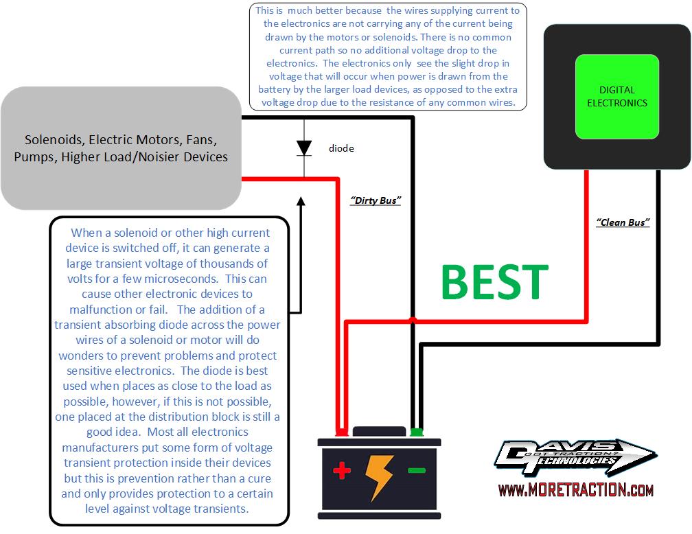
4 Transients The second demon in racing electronic systems is transient voltage. In electronics, the word transient is used to describe a short-duration condition triggered by an event. For example, when you remove power from an energized solenoid, a short duration (microsecond) pulse of high voltage is generated. This spike of voltage, when left uncontrolled, can wreak havoc on the microcontrollers in the system. There are a lot of transient events in an automotive system, but the most concerning are those that generate a high voltage. This includes the ignition spark. Unmanaged, high-voltage spikes can cause problems that are very hard to troubleshoot. The effects are unpredictable and difficult to reproduce in testing. Transients are managed with preventative measures, rather than diagnostics. Transients are generated by power devices, such as solenoids, relays and coils, and most harmful to control devices. Transients can be managed with the use of diodes across the coils, as well as proper wiring techniques. Every solenoid or relay in the car should have a suppression diode installed, some relays, or controllers, MAY have the diode built, other may not. Simply changing a relay, could cost you weekends of failed racing. We recommend, and there is no harm in, adding a diode as insurance, not to mention it may improve the performance of a coil-driven device. (Diode # 1N4002, 1N4004, 1N4006 or similar) Example of a couple of way to possible install a protection diode. solenoid

 Not hard to see how these voltage spikes can cause problems. These spikes can happen on either the positive, or negative side, depending on the circuit.")
5 Example of a small air control solenoid producing a 396V transient voltage spike upon turning off. The yellow trace shows a 396 volt spike created when a solenoid is deenergized. This spike can travel throughout the cars wiring, causing resets or failures of other electronics in the car. Pink trace is the solenoid on/off signal. With a diode installed across the coil of the solenoid, the transient voltage spike is absorbed by the diode and not allowed to travel throughout the car, protecting the other electronics. (Diode# 1N4002, 1N4004, 1N4006 or similar) Not hard to see how these voltage spikes can cause problems. These spikes can happen on either the positive, or negative side, depending on the circuit. Just think of how your electronics feel about a 400 volt spike running through them.
6 Wiring The general rule when wiring power and ground is to avoid sharing the connections between power devices and control devices. This is especially important for ground connections, but power connections should also be separate wherever possible. It is safe to assume that power devices generate the problems that control devices can t tolerate. If the two categories of devices are connected to separate ground/power busses, it limits the transfer of problems from one to the other. Adding an additional ground wire to connect the 2 buses, a common ground like your friend suggested, is actually horrible. This may cause problems as opposed to fixing them you CAN have too many grounds- especially if they go to the wrong places. To this end, the best plan is to create a Clean Bus for the control devices and a Dirty Bus for the power devices. The goal of the clean bus is to minimize voltage drops, so it needs to be built with low-resistance cable and terminals. The goal of the dirty bus is to handle large currents, so it also needs to be built with low-resistance cables and terminals. In other words, use high-quality, low-resistance materials and methods for both. The 2AWG cable that handles 100 Amps without heating up will provide a quality ground reference when carrying 3 Amps for the control devices, a #10 AWG WILL NOT provide sufficient ground path to the battery. This is not the place to save weight at the expense of unreliable operation of your electronics. Chassis Ground Dependence on chassis ground should be minimized. The chassis may be grounded to the battery negative terminal, providing a definite ground path to chassis, not accidentally grounded through the engine or other purposefully grounded part. Grounding devices to the chassis should be avoided. Instead, ground them to the appropriate bus. The Clean Bus ground should not connect to chassis, ONLY TO BATTERY NEGATIVE TERMINAL!
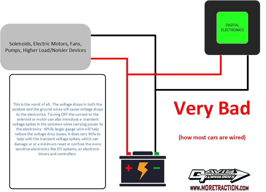
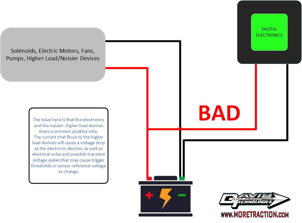
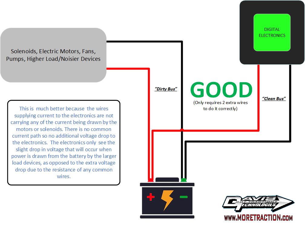
7 Summary In a perfect world, if the battery were safely mounted and protected in a central location, this would be best. As we all know, it is usually remotely located do to weight, rules, safety or other overriding factors. To be clear, every electrical device in the car should be grounded directly to the battery terminal. With the battery within reach, connecting the grounds properly would be easy, however this is not realistic, so some compromise must be found. The best compromise is the separation of the grounds in the form of a Dirty Bus and a Clean Bus. The Clean bus can allow for a distribution block located in a more central area of the car for simpler wiring and neatness. This distribution block should be supplied with a large cable, like 1/0 gauge cable. Again, you may compromise and get away with a smaller gauge, but cable smaller than a minimum of 2 gauge should NOT be used. The larger wire size and a few ounces is cheap insurance against problems, aggravation and lost weekends. Plus, chicks dig big wires! This Clean Bus Distribution block can be used as the voltage source for the various toggle switches and devices as well as the power source for the low current draw control devices like boost controllers, sensors, data loggers, traction control or ignition controls. The Dirty Bus can allow for a distribution block located in a more central area of the car for ease of access. This Dirty Bus Distribution block can be used as the voltage source for things like solenoids, coils, or other high current draw devices. This distribution block should be supplied with a large cable (2/0 gauge or larger). Compromise here and suffer! Main power leads for devices such as EFI boxes, Ignition Boxes or Coil Drives MUST be connected to the battery terminals or at worst to the Master kill switch located near the battery! Most every manufacturer specifies this and it is very important for reasons you will see below. Here are few different ways of wiring a simple circuit with a battery, a motor or solenoid and an electronic device. To keep things simple, only the major components are shown. Electrically they are all the same in that they are all connected to positive and negative and will turn on/off. Electronically, however, the example labeled Bad, and Worst are likely to cause problems and lots of aggravation! The one labeled Good will probably work, but Best is the way it should be done. If your wiring guy is not following the simple methods shown in the Best example- get someone else to do it. Running a pair of large gauge wires from the battery to distribution blocks and connecting EVERYTHING to those blocks is VERY BAD!!! It may look good and be easy- but, it will NOT work properly. As shown in the Best example, the proper method is to have a Clean Bus with only electronics connected to that bus, and a Dirty Bus with the higher current draw and noisier devices connected to that bus.
8 Important Notes- Use the proper gauge wire EVERY solenoid should have a protection diode installed- even if you have never heard of that! Do Not depend on the chassis to be a proper ground Ground each cylinder head to the battery ground (Dirty Bus) connect each cylinder head to coil negative post if compatible. Since the chassis will probably get a partial ground from the engine- Run a grounding strap from Dirty Bus ground to chassis to make sure it is properly grounded. Stay away from Butt splices- just don t use them. Ignore your buddy who says I never did that and mine works fine Here is a list of devices commonly found in racecars that can cause problems to electronics wired to the same circuit. The main power wires of these devices should be connected to the Dirty Bus. Ignition Boxes (main power wires- not the on/off ignition wire) Injector Drivers (main power wires- not the on/off ignition wire) EFI (main power wires- not the on/off ignition wire) Starter motors/starter solenoids Solenoids Relays Pumps Electric Blowers Electric fans Headlight bulbs These devices should be connected to the Clean Bus. Traction Control Ignition On/Off EFI On/Off Boost Controllers Shift Controller Timers Data Loggers Dash Sensors / Instruments
9
10
11
12
13


14 PUMPS Ignition To trans brake control devic es Diode Dirty Bus Ign Bus Dirty Bus Diode To Ignition Bus Pumps Simple Trans Brake Diode Clean Bus- ignition Ignition bus Dirty Bus Main power wires direct to battery Ign Bus Clean bus Dirty Bus 2 gauge 0/0 gauge Dirty Bus To trans brake control devic es


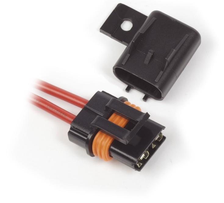
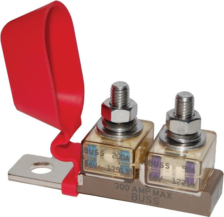
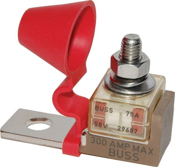

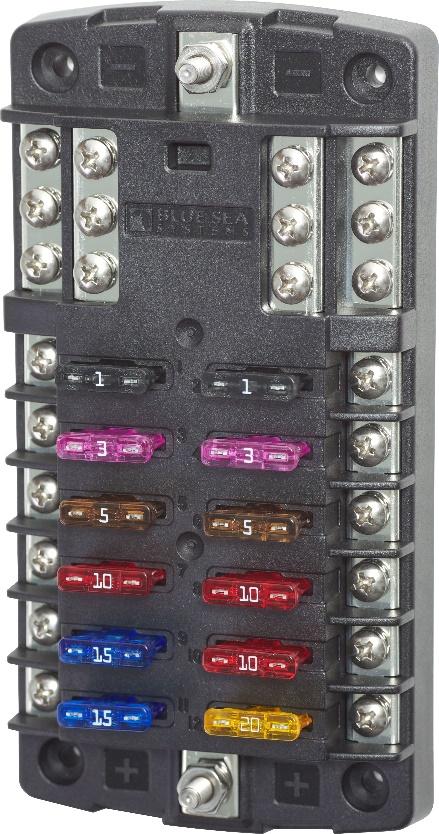
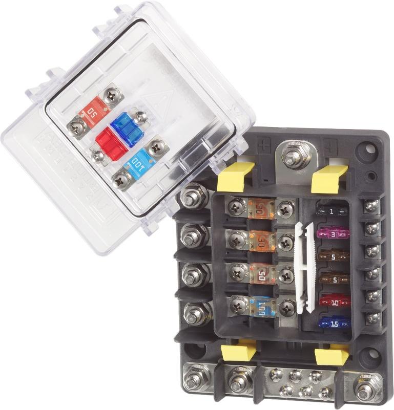
15 Useful Hardware From Blue Sea Systems


16
ECT Display Driver Installation for AP2 Module
 ECT Display Driver Installation for AP2 Module Overview The ECT Display Driver is a small module with a removable wire harness that mounts behind the driver's foot well cover. All wiring connections are
BASIC ELECTRICAL MEASUREMENTS By David Navone
 BASIC ELECTRICAL MEASUREMENTS By David Navone Just about every component designed to operate in an automobile was designed to run on a nominal 12 volts. When this voltage, V, is applied across a resistance,
Electrical Systems. Introduction
 Electrical Systems Figure 1. Major Components of the Car s Electrical System Introduction Electricity is used in nearly all systems of the automobile (Figure 1). It is much easier to understand what electricity
Wired Real Time GPS Installation Instructions
 Wired Real Time GPS Installation Instructions This page intentionally left blank. TABLE OF CONTENTS 1. Introduction 2 2. Selecting the Mounting Location for the Device. 3 3. Mounting the Device 5 4. Optional
MSD 7AL-3, Ignition Control PN 7230
 MSD 7AL-3, Ignition Control PN 7230 Important: Read the instructions before attempting the installation. Parts Included: 1-7AL-3, PN 7230 1 - Parts bag (wires and connectors) 4 - RPM Modules 3000, 7000,
The Physics of the Automotive Ignition System
 I. Introduction This laboratory exercise explores the physics of automotive ignition systems used on vehicles for about half a century until the 1980 s, and introduces more modern transistorized systems.
Selected excerpts from the book: Lab Scopes: Introductory & Advanced. Steven McAfee
 Selected excerpts from the book: Lab Scopes: Introductory & Advanced Steven McAfee 1. 2. 3. 4. 5. 6. Excerpt from Chapter 1 Lab Scopes How do they work? (page 6) Excerpt from Chapter 3 Pattern Recognition
In the first part of this series on
 by Mike Van Dyke In the first part of this series on diagnosing ECUs, we went over some basic visual diagnosis of common failures. In this, the second part of the series, we re going to go over some basic
Contacts The moveable contact, which is the one affected by the armature is sometimes referred to as the hinge contact.
 Relays & Wiring 101 Basically, a relay is an electrically operated, remotely controlled switch. A simple electromagnetic relay is an adaptation of an electromagnet. It consists of a coil of wire surrounding
MB A 12V/24V DC PROGRAMMABLE DUAL BATTERY ISOLATOR
 MB-3688 120A 12V/24V DC PROGRAMMABLE DUAL BATTERY ISOLATOR User Manual Warning and Precautions MB-3688 is built with corrosion resistant material and the main electronic assembly is well sealed inside
Electronic Dynamo Regulator INSTRUCTION MANUAL. COPYRIGHT 2015 CLOVER SYSTEMS All Rights Reserved
 DR310 TM Electronic Dynamo Regulator INSTRUCTION MANUAL COPYRIGHT 2015 CLOVER SYSTEMS All Rights Reserved INTRODUCTION The Clover Systems DR310 is an allelectronic voltage and current regulator for dynamos
SCHNITZ MOTORSPORTS PNC-202, 2-STAGE PROGRESSIVE NITROUS CONTROLLER USER MANUAL AND INSTALLATION GUIDE NOS PULSE FREQUENCY
 SCHNITZ MOTORSPORTS PNC-202, 2-STAGE PROGRESSIVE NITROUS CONTROLLER USER MANUAL AND INSTALLATION GUIDE NOS #2, FUEL SOLENOID(GROUND) 1GA PURPLE, PAGE 14 NOS #2 NITROUS SOLENOID(GROUND) 1GA PURPLE, PAGE
USER MANUAL AND INSTALLATION GUIDE ENGINE RPM AND NOS SHIFT COUNTER NOS DELAY TIME IN SECONDS NOS START PERCENT NOS FINAL PERCENT
 SCHNITZ MOTORSPORTS DSC-9PS "PRO-STREET" IGNITION CONTROLLER USER MANUAL AND INSTALLATION GUIDE SHIFT LIGHT POSITIVE PAGE 2 SHIFT LIGHT GROUND PAGE 2 NOS SOLENOID GROUND 1GA ORANGE, FUEL SOLENOID GROUND
Electronic Dynamo Regulator INSTRUCTION MANUAL. COPYRIGHT 2014 CLOVER SYSTEMS All Rights Reserved
 DRM TM DRM-HP TM Electronic Dynamo Regulator INSTRUCTION MANUAL COPYRIGHT 2014 CLOVER SYSTEMS All Rights Reserved INTRODUCTION The Clover Systems DRM is a state-of-the art all-electronic voltage and current
PRESEASON CHASSIS SETUP TIPS
 PRESEASON CHASSIS SETUP TIPS A Setup To-Do List to Get You Started By Bob Bolles, Circle Track Magazine When we recently set up our Project Modified for our first race, we followed a simple list of to-do
TONY S TECH REPORT. Basic Training
 TONY S TECH REPORT (Great Articles! Collect Them All! Trade them with your friends!) Basic Training OK YOU MAGGOTS!! Line up, shut up, and listen good. I don t want any of you gettin killed because you
Ignition Installation Troubleshooting Tips/Frequently-Asked Questions
 Ignition Installation Troubleshooting Tips/Frequently-Asked Questions Warning: Reversing the red and black ignition wires will destroy the ignition module and void the warranty. The Hot-Spark module s
SCHNITZ MOTORSPORTS USER MANUAL AND INSTALLATION GUIDE PRO-MOD BATTERY VOLTS DIAGNOSTICS NOS PULSE FREQUENCY NOS DELAY TIME IN SECONDS
 SCHNITZ MOTORSPORTS DSC-CS "PRO-MOD" IGNITION CONTROLLER USER MANUAL AND INSTALLATION GUIDE COIL, (OPTIONAL) GA YELLOW, COIL, NEGATIVE GA WHITE, GA BLACK, SHIFT LIGHT +V OUTPUT PAGE 0 NOS ACTIVATION INPUT
SOME BASICS OF TROUBLESHOOTING
 SOME BASICS OF TROUBLESHOOTING DICK RANDALL I decided to pull these ideas together because I have spent plenty of hobby time figuring out things that did not work or that needed repair. This process and
Froggy. We began our dissection of the Mazda. Mazda Retractable Headlights: Part Two
 Froggy came a-shortin azda Retractable Headlights: Part Two We began our dissection of the azda iata retractable headlight system in Part One (April 2001 Import Service). The first article covered the
Phase 1 Workshop Home Study Guide
 Phase 1 Workshop Home Study Guide Vehicle Electrical-Electronics Troubleshooting Training Written and Developed by Vince Fischelli Director of Training Veejer Enterprises Inc. / Garland, Texas U.S.A. Phone:
CONTROLLER DIAGNOSTIC GUIDE
 Proprietary tice: This document contains proprietary information which not to be reproduced, transferred, to other documents, disclosed to others, used for manufacturing or any other purpose without the
Installation Tips for your Remote Start system (for RS4LX>GMBP for GM vehicles)
") Installation Tips for your Remote Start system (for RS4LX>GMBP for GM vehicles) Thank you for purchasing your remote start from MyPushcart.com - an industry leader in providing remote starts to doit-yourself
Installation Tips for your Remote Start system (for RS4LX>GMBP for GM vehicles) Thank you for purchasing your remote start from MyPushcart.com - an industry leader in providing remote starts to doit-yourself
TIP SHEET T0937. Installation Tips For RS00/PS00 + ADS-TBSL-PL + SPDT
 Installation Tips For RS00/PS00 + ADS-TBSL-PL + SPDT TIP SHEET T0937 Thank you for purchasing your remote start from MyPushcart.com - an industry leader in providing remote starts to do-it-yourself installers
By Bob Markiewicz. Figure 1. Figure 2
 can greatly help you develop horsepower and better understand ignition timing. By understanding the mixture burns at a slow rate, compared to an explosion, and knowing that by increasing this burn rate
USER MANUAL AND INSTALLATION GUIDE TIMER DELAY IN SECONDS SHIFT STYLE & SHIFT COUNTER TIMER DURATION NOS DELAY TIME IN SECONDS NOS START PERCENT
 SCHNITZ MOTORSPORTS DSC-TG0- "TOP-GAS " IGNITION CONTROLLER USER MANUAL AND INSTALLATION GUIDE COIL, (OPTIONAL) GA YELLOW, PAGE COIL, NEGATIVE GA WHITE, PAGE SHIFT LIGHT GROUND 0GA BROWN, PAGE 0 SHIFT
CradlePoint Vehicle Best Practices Installation Guide
 CradlePoint Vehicle Best Practices Installation Guide Using CradlePoint Routers in 12V and 24V Vehicles Revision 1.2 Overview The automotive environment can be particularly harsh for electrical equipment
DYNAMIC DUO. Lab scopes and current
 DYNAMIC DUO Combining the data acquisition capabilities of a lab scope with the versatility of a current probe gives you a powerful diagnostic tandem that s awfully hard to beat. BY MARK WARREN Lab scopes
ELECTRICAL. Contents - Wiring Diagrams
 Contents - Wiring Diagrams T-Bar (Floating Deck - Hydro)............................................ 8-16 T-Bar (Fixed Deck - Gear)............................................... 8-17 T-Bar (Fixed Deck
SST-3 Start-Stop-Throttle
 SST-3 Start-Stop-Throttle Installation & Operation Guide Revision 1.1 Internet: www.wiredrite.com E-mail: info@wiredrite.com Page 1 CONTENTS Introduction 2 Hardware Mounting 2 Connections 2 Operation &
Ignition Coil Current Waveforms 2007 Honda Accord SE 4CYL
 P a g e 1 Ignition Coil Current Waveforms 2007 Honda Accord SE 4CYL With a current clamp and a cheap scope, it is easy to monitor the ignition coil currents and quickly diagnose a bad ignition coil. The
Modifying a 5.0 Mustang MAF EFI Harness for Standalone Operation in Another Vehicle
 Modifying a 5.0 Mustang MAF EFI Harness for Standalone Operation in Another Vehicle Starting Point: A used harness can be sourced from any 5.0 equipped Mustang with Mass Air Flow (MAF). MAF was first introduced
# Traction Control Window Switch
 1 INSTRUCTIONS # 82085 Traction Control Window Switch Thank you for choosing products; we are proud to be your manufacturer of choice. Please read this instruction sheet carefully before beginning installation,
Battery-Back-Up Power for Amateur Radio
 Battery-Back-Up Power for Amateur Radio These days of instant communications, we seem to rely on our cordless and cell phones, HTs and mobile rigs for our communications needs. One item we always seem
INSTALLATION GUIDE. FCC ID NOTICE
 REV.5 RS. ADVANCED REMOTE STARTER INSTALLATION GUIDE www.security.soundstream.com FCC ID NOTICE This device complies with Part 5 of the FCC rules. Operation is subject to the following conditions:. This
Installation Instructions for Lingenfelter Shift Light Controller with green LED
 Installation Instructions for Lingenfelter Shift Light Controller with green LED PN: L460080000 1557 Winchester Road Decatur, Indiana 46733 260 724 2552 phone 260 724 8761 fax www.lingenfelter.com Parts
Asynchronous Restriking CDI 2 channel
 Asynchronous Restriking CDI 2 channel Parts List ARC-2 module Decals Power Cable Fuse Specifications Operating Voltage: 8-20V Operating Current: Max Operating RPM: Ambient Temp range: Ignition inputs:
J71 AUTOMATIC APPLY PARKING BRAKE (aapb), Toubleshooting and Repair Information
, Toubleshooting and Repair Information") J71 AUTOMATIC APPLY PARKING BRAKE (aapb), Toubleshooting and Repair Information By sb1 at irv2.com, Aug 14, 2012. I have a 2003 Damon DayBreak 3285 with 25,000 miles. Though the coach is a 2003 model,
J71 AUTOMATIC APPLY PARKING BRAKE (aapb), Toubleshooting and Repair Information By sb1 at irv2.com, Aug 14, 2012. I have a 2003 Damon DayBreak 3285 with 25,000 miles. Though the coach is a 2003 model,
Exhaust System Bypass Valves and Exhaust Valve Bypass Controller
 Exhaust System Bypass Valves and Exhaust Valve Bypass Controller Basic Primer on Exhaust System Flow Velocity and Backpressure The information about exhaust system theory was obtained from research on
INSTRUCTIONS FOR TRI-METRIC BATTERY MONITOR May 8, 1996
 INSTRUCTIONS FOR TRI-METRIC BATTERY MONITOR May 8, 1996 PART 2: SUPPLEMENTARY INSTRUCTIONS FOR SEVEN TriMetric DATA MONITORING FUNCTIONS. A: Introduction B: Summary Description of the seven data monitoring
1 Function Scope of Delivery Mounting Electrical Connections Initial Setup Troubleshooting...
 Elektronik Sachse MHP GmbH & Co. KG Installation Manual Digital Ignition ZDG 3.23 (Ducati Mille) Item: Z73 version: f4feb00 Contents 1 Function.......................................................................
SERVICE MANUAL. Kysor Instrumentation Troubleshooting Guide
 Kysor Instrumentation Troubleshooting Guide Troubleshooting Emergency One Commercial System The Medallion II instrumentation system is a Microprocessor based system utilizing both Sensor and Data bus information
SM361 RIG SWITCH CONSTRUCTION MANUAL
 SM361 RIG SWITCH CONSTRUCTION MANUAL Document ver 1, For software release ver 1.1 May 27, 2016 Controls the power of 12V equipment while a vehicle is in use Product Development by: SM361 RIG SWITCH OVERVIEW
Mega 475
 www.racedigitaldelay.com Mega 475 Instruction Manual - 1 - The MEGA 475 From DIGITAL DELAY 2036 Fillmore Street Davenport Iowa 52804 563-324-1046 www.racedigitaldelay.com Congratulations on your purchase
Overcurrent protection
 Overcurrent protection This worksheet and all related files are licensed under the Creative Commons Attribution License, version 1.0. To view a copy of this license, visit http://creativecommons.org/licenses/by/1.0/,
HOW TO USE A MULTIMETER, PART 4: MEASURING CURRENT (AMPERAGE)
") HOW TO USE A MULTIMETER, PART 4: MEASURING CURRENT (AMPERAGE) By: Rob Siegel First, we discussed how to use a multimeter for measuring voltage, or simply verifying that voltage is present. Last week, we
HOW TO USE A MULTIMETER, PART 4: MEASURING CURRENT (AMPERAGE) By: Rob Siegel First, we discussed how to use a multimeter for measuring voltage, or simply verifying that voltage is present. Last week, we
2 WAY REMOTE STARTER & ALARM SYSTEM INSTALLATION GUIDE FCC ID NOTICE
 REV. ARS. WAY REMOTE STARTER & ALARM SYSTEM INSTALLATION GUIDE FCC ID NOTICE This device complies with Part 5 of the FCC rules. Operation is subject to the following conditions:. This device may not cause
jegs.com
 Contents Wiring Harness w/ Fuse Panel Installation Instructions Turn Signal Plug w/ Terminals 2 Headlight Plugs 3/4 Grommet 10 ¼ Terminals 4 Ring Terminals 10 Wire Ties Fusible Link 2 Screws & Nuts 2 Plastic
Off-Road Switch Panel Installation Instructions
 Off-Road Switch Panel Installation Instructions 50330: Off-road 4 Toggle switches/dash Mount w/keyed Ignition Switch 50332: Off-road 6 Toggle switches/dash Mount w/keyed Ignition Switch Painless Performance
Torque Convertor Control System
 22 September 2015 PN#1030395 TorqLoc (I-00208) 1 BD TorqLoc Torque Convertor Control System Part# 1030395 Installation Manual for the following applications: BD Brakes for Dodge, Ford and Chevrolet Pac
ELECTRICITY AND HWH COPPER CONDUCTOR
 1. PREFACE +BATTERY TERMINAL +BATTERY TERMINAL + + + + + + + + + + + + ELECTRICITY AND HWH In the first section of this school, we did an in-depth study of general hydraulics. In section four, we applied
1 Function Scope of Delivery Mounting Electrical Connections Initial Setup Troubleshooting...
 SACHSE Elektronik Sachse MHP GmbH & Co. KG Installation Manual Digital Ignition ZDG 3.23 (Honda CB72/ 77) Item: Z06-CB72 version: 62aa227 Contents 1 Function.......................................................................
Why is the Breaker Tripping?
 Why is the Breaker Tripping? Breakers are designed to trip anytime the circuit draws a current above the rating for a period of time. The time the breaker takes to trip is a function of how high the circuit
30140 F5 Dual Fan Controller
 30140 F5 Dual Fan Controller 1 2501 Ludelle Street Fort Worth, Texas 76105 817-244-6212 Phone 817-244-4024 Fax 888-350-6588 Sales 800-423-9696 Tech E-mail: painless@painlessperformance.com Web: www.painlessperformance.com
elabtronics Voltage Switch
 elabtronics Voltage Switch Want to trigger a device when a monitored voltage, temperature or light intensity reaches a certain value? The elabtronics Voltage Switch is an incredibly easy way of doing it.
Prove all things; hold fast that which is good.1 Thessalonians 5:21
 ELECTRICAL TROUBLE SHOOTING Prove all things; hold fast that which is good.1 Thessalonians 5:21 Electrical problems can pop up at any time and can seem hard to fix but they really aren't. Most of the time,
Timing is everything with internal combustion engines By: Bernie Thompson
 Timing is everything with internal combustion engines By: Bernie Thompson As one goes through life, it is said that timing is everything. In the case of the internal combustion engine, this could not be
Roehrig Engineering, Inc.
 Roehrig Engineering, Inc. Home Contact Us Roehrig News New Products Products Software Downloads Technical Info Forums What Is a Shock Dynamometer? by Paul Haney, Sept. 9, 2004 Racers are beginning to realize
Electro Wizard TM Battery Disconnect Switch
 Electro Wizard TM Battery Disconnect Switch FR1051 Technical Specifications Grounded Solenoid (Power Supply Coil Negative) CHARACTERISTICS FR1051 Nominal tension Max 12V Max. continuous current on main
CONTROL BOX. Wiring the control box into the vehicle. +12V
 CONTROL BOX Once the display panel is in place, mount the control box within the connecting cable's distance (approximately 3 feet) and secure to the underside of the dashboard. This case does not have
ELITE 625 With Dial Display Control
 www.racedigitaldelay.com ELITE 625 With Dial Display Control Instruction Manual - 1 - The ELITE 625 From DIGITAL DELAY 2036 Fillmore Street Davenport Iowa 52804 563-324-1046 www.racedigitaldelay.com Congratulations
ELECTRONIC TRACTION CONTROL USER MANUAL
 DRAG-SPORTSMAN N2O For ELECTRONIC TRACTION CONTROL USER MANUAL TELEPHONE 828.645.1505 FAX 828.645.1525 WWW.MORETRACTION.COM US PATENT 6,577,944 Disclaimer...2 Introduction... 3 How Does It Work. 4 Installation...
Last updated: February 15, 2007
 Last updated: February 15, 2007 NOTICE: We sell these with complete wiring packs, and with just the Vegtherm tube itself plus the relay, wiring plug for relay, and circuit breaker. There are two different
Electronic Ignition for HONDA CB Fours
 Electronic Ignition for HONDA CB350-400-500-550-750 Fours THE Accent SYSTEM The use of electronic ignition systems on motorcycles has shown a good performance over the last decades. Unfortunately, older
Converting an A to 12v and Adding Turn Signals Bill Lee
 Converting an A to 12v and Adding Turn Signals Bill Lee Bill@WRLee.com When I bought my 1929 Tudor, it had been restored about 20 years earlier. It had halogens and had been converted to 12v negative ground,
Installation Instructions For 50330, 50331, 50332, and Off Road Switch Panels
 Installation Instructions For 50330, 50331, 50332, and 50333 Off Road Switch Panels 2501 Ludelle Street Fort Worth, Texas 76105 817-244-6212 Phone 817-244-4024 Fax 888-350-6588 Sales 800-423-9696 Tech
Inside a typical car engine. Almost all cars today use a reciprocating internal combustion engine because this engine is:
 Tech Torque HOW PETROL ENGINES WORK The Basics The purpose of a gasoline car engine is to convert gasoline into motion so that your car can move. Currently the easiest way to create motion from gasoline
ALTERNATOR PRECAUTIONS. Some precautions should be taken when working on this, or any other, AC charging system.
 The alternator charging system is a negative (-) ground system which consists of an alternator, a regulator, a charge indicator, a storage battery and wiring connecting the components, and fuse link wire.
EDITOR'S NOTE: This article replaces "Use PGM FI Data List to Help Troubleshoot Inoperative A/C," issued in June 2012.
 2001 Honda Civic 1.7L Eng LX TROUBLESHOOTING AN INOPERATIVE A/C TECHNICAL SERVICE BULLETIN Reference Number(s): 13 080J, Date of Issue: August, 2013 HONDA: '00 and later models with A/C APPLIES TO: '00
Troubleshooting Guide for N1225-1/N1237-1/N Alternators
 Troubleshooting Guide for N1225-1/N1237-1/N1505-1 Alternators Hazard Definitions These terms are used to bring attention to presence of hazards of various risk levels or to important information concerning
To avoid a short cut please file off the right half of the Y-hole flange.
 Fitting instructions for automatic alternator controller for Moto Guzzi with Bosch alternator 1. alternator modification - 2. Fitting - 3. adjustment (ignition only) First remove the connector block of
A $10 Upgrade to my Harbor Freight 90 Amp Flux Wire Welder, version 2
 A $10 Upgrade to my Harbor Freight 90 Amp Flux Wire Welder, version 2 By R. G. Sparber Copyleft protects this document. 1 My Harbor Freight 90 amp flux wire welder is surprisingly good. But as with most
Page 3. Misc. insulator pads to go under the inverter and spark box. I used the packing material from around a glass jar
 Page 1 Convert vehicle 1978 Chevy Camaro with stock 350 engine, automatic trans. Stock 4-barrel carb, and stock fuel pump. The gas tank has been changed to a metal water tank and the fill cap is vented
Installation Tips for your Crimestopper/ProStart Remote Start system (add-on for GM vehicles) v1.02 updated 1/16/2013
 v1.02 updated 1/16/2013") Installation Tips for your Crimestopper/ProStart Remote Start system (add-on for GM vehicles) v1.02 updated 1/16/2013 Thank you for purchasing your remote start from MyPushcart.com - an industry leader
Installation Tips for your Crimestopper/ProStart Remote Start system (add-on for GM vehicles) v1.02 updated 1/16/2013 Thank you for purchasing your remote start from MyPushcart.com - an industry leader
CP 634 DELUXE 4-CHANNEL KEYLESS ENTRY SYSTEM
 CP 634 DELUXE 4-CHANNEL KEYLESS ENTRY SYSTEM Installation And Operation Manual MEGATRONIX VAN NUYS, CA U.S.A. CP634 1 REMOTE CONTROL CONVENIENT SYSTEM INSTALLATION & OPERATION INSTRUCTIONS INTRODUCTION
ELITE 600
 www.racedigitaldelay.com ELITE 600 Instruction Manual - 1 - The ELITE 600 From DIGITAL DELAY 2036 Fillmore Street Davenport Iowa 52804 563-324-1046 www.racedigitaldelay.com Congratulations on your purchase
DOC # DOCSST-D 08/16/99
 DOC # DOCSST-D 08/16/99 Wired Rite Systems 5793 Suite A, Skylane Blvd., Windsor Ca. 95492 Phone: (800) 538-7483 Or (707) 838-1122 Fax: (800) 525-7483 WEB: http://www.wiredrite.com E-MAIL: Info@wiredrite.com
The Driver s Guide to
 FREE EBOOK The Driver s Guide to Automotive Maintenance 1 The Driver s Guide to Automotive Maintenance Routine automotive maintenance is arguably the most important thing you can do for your car. It may
Torque Convertor Control System
 1 BD AutoLoc Torque Convertor Control System Part# 1030390 Installation Manual for the following applications: BD Brakes for Dodge, Ford and Chevrolet Pac Brake for Dodge & Ford Jacobs E-Brake for 1994-98
Throttle and Shift by Wire
 Throttle and Shift by Wire Full Electronic Engine Control is now available at your fingers tips Imagine you re planning your new ideal boat. It will have two, no, three large modern lowemission outboard
Do isolate the power supply from other high power systems such as Stereos and Alarms
 Thank you for purchasing a Smart Ride Air Management System, AIRBAGIT.COM s premier flagship product. This system will meet all of your custom and utility needs and will provide you years of trouble free
Vehicle Reaction Timer Instructions
 Vehicle Reaction Timer Instructions The Computech Systems Vehicle Reaction Timer is designed to very accurately measure the time from when your vehicle is instructed to launch to when it actually begins
MBCM-24 MULTIPLE BATTERY CHARGING MODULE (FOR MARINE APPLICATIONS) FEATURES SPECIFICATIONS APPLICATIONS DESCRIPTION & OPERATION ORDERING INFORMATION
 FEATURES SPECIFICATIONS APPLICATIONS DESCRIPTION & OPERATION ORDERING INFORMATION") FEATURES Extends the trolling motor run time by charging the trolling motor batteries each time the boat s main engine is used. Automatically senses engine s alternator charge voltage, connects trolling
FEATURES Extends the trolling motor run time by charging the trolling motor batteries each time the boat s main engine is used. Automatically senses engine s alternator charge voltage, connects trolling
What You Need at the Flying Field
 What You Need at the Flying Field The following items are considered necessary for the R/C pilot to have available in the field. Several of the items are needed right away and others might be needed at
N1387 Series Troubleshooting Guide for N Alternators
 N1387 Series Troubleshooting Guide for N1387-1 Alternators Hazard Definitions These terms are used to bring attention to presence of hazards of various risk levels or to important information concerning
Troubleshooting Guide for Limoss Systems
 Troubleshooting Guide for Limoss Systems NOTE: Limoss is a manufacturer and importer of linear actuators (motors) hand controls, power supplies, and cables for motion furniture. They are quickly becoming
OFF-ROAD ELECTRONIC IGNITION CONTROL
 INSTALLATION INSTRUCTIONS FORM 1678M 05/07 OFF-ROAD ELECTRONIC IGNITION CONTROL GENERAL INFORMATION This ignition includes a single stage RPM limiter. You can set various settings using the switches that
INSTALLATION INSTRUCTIONS. Revision 4.0.3
 INSTALLATION INSTRUCTIONS Revision 4.0.3 Table of Contents INTRODUCTION... 3 INSTALLATION OVERVIEW... 4 Included Parts... 5 DEVICE WIRING... 6 Required Parts... 6 Guidelines... 6 Wiring Diagram... 7 Engine
UNIVERSAL GAUGE WIRE HARNESS
 2650-1797-00 UNIVERSAL GAUGE WIRE HARNESS For Installing Auto Meter Electric Speedometer, Tachometer, And Short Sweep Electric Oil Pressure, Water Temperature, Fuel Level, and Volt Meter Gauges. This harness
MOTOR CONTROLLERS. STATE the function of motor controllers.
 Electrical Distribution Systems Motor controllers range from a simple toggle switch to a complex system using solenoids, relays, and timers. The basic functions of a motor controller are to control and
HOW TO USE A MULTIMETER, PART 1: INTRODUCTION
 HOW TO USE A MULTIMETER, PART 1: INTRODUCTION By: Rob Siegel First, thanks for all the comments, both here and on my Facebook page, about the piece on Electrical Safety two weeks ago. I felt that, if I
BigStuff3 - GEN3. 1st Gear Spark Retard with Spark Retard Traction Control System (SR 2 ) Rev
 Rev") BigStuff3 - GEN3 1st Gear Spark Retard with Spark Retard Traction Control System (SR 2 ) 12-09 System Description 1st Gear Spark Retard with Spark Retard Traction Control System (SR 2 ) - SR 2 uses two
BigStuff3 - GEN3 1st Gear Spark Retard with Spark Retard Traction Control System (SR 2 ) 12-09 System Description 1st Gear Spark Retard with Spark Retard Traction Control System (SR 2 ) - SR 2 uses two
CUSTOMER WIRING INSTRUCTIONS TO SUIT: BA-BF XR6 and XR8 Universal Auto or Manual Trans
 , CUSTOMER WIRING INSTRUCTIONS TO SUIT: BA-BF XR6 and XR8 Universal Auto or Manual Trans Lay the C.A.E Engine loom in vehicle and plug in all the sensors. ( The sensor plugs can only be connected one way
Fuel gauge problems. Mon, :42 Anonymous
 Fuel gauge problems Mon, 2009-10-12 14:42 Anonymous FuelgaugeIf you own a WW2 vintage MB / GPW Jeep you will be well aware of the annoying guessometer in the dash panel - otherwise known as the fuel gauge.
GVW AGM Auxiliary Battery Kit for Vanagon Westfalia Full Camper
 GVW-253-700AGM Auxiliary Battery Kit for 1983-1991 Vanagon Westfalia Full Camper The purpose of this kit is to add an Interstate SLA1161 as an auxiliary battery under the driver's seat of 1983 to 1991
Tempest Tech-Tip 0813
 August 2013 Tempest Tech-Tip 0813 Light My Fire Background Without a good spark, spark plugs can t get the job done well. How do you keep good sparks coming, so your spark plugs can light your fire with
C.E. Niehoff & Co. N1601, N1602, N1603, and N1604 Alternator Troubleshooting Guide NOTICE. Hazard Definitions. Battery Charge Volt and Amp Values
 C.E. Niehoff & Co. N1601, N1602, N1603, and N1604 Alternator Troubleshooting Guide Hazard Definitions These terms are used to bring attention to presence of hazard(s) of various risk levels or to important
Troubleshooting Guide for Okin Systems
 Troubleshooting Guide for Okin Systems More lift chair manufacturers use the Okin electronics system than any other system today, mainly because they re quiet running and usually very dependable. There
Required Power Inputs and Grounds for Ford Modular V8 EEC-V engines (99-04) Last Modified: Revision: 1.0
 Last Modified: Revision: 1.0") This document has been created to point out main power inputs and grounds for the Ford EEC-V harness for swapping a modular V8 engine into another vehicle. This document may not be fully exhaustive of
This document has been created to point out main power inputs and grounds for the Ford EEC-V harness for swapping a modular V8 engine into another vehicle. This document may not be fully exhaustive of
Troubleshooting of the LubeTech Grease System
 Troubleshooting of the LubeTech Grease System February 2009 The LubeTech grease system is designed to be a preventative maintenance system that will extend the life of your bearings that are connected