Mega 475
|
|
|
- Lenard Brown
- 6 years ago
- Views:
Transcription

1 Mega 475 Instruction Manual - 1 -
2 The MEGA 475 From DIGITAL DELAY 2036 Fillmore Street Davenport Iowa Congratulations on your purchase of the Mega 475 the latest delay box from Digital Delay. The Mega 475 is the first Delay box from Digital Delay to control a digital Dial Display board. The Mega 475 can control any Digital Delay version 2 Dial Display boards, including multiple display boards and our Dual View display boards. To design the Mega 475 we started with the Mega 450 added the new ability to control a Dial Display board. Then we further improved the design by adding some new features and upgrading others, while retaining everything that made the original Mega 450 the bestselling Delay Box. The Mega 475 may seem overwhelming at first. But even if you have never owned a Mega or Elite series Delay Box, the layout of the screens, and the commonality of how data is entered and viewed on the screens, eases the learning process of the Mega 475. Digital Delay also offers a wiring kit for the Mega 475 to help with the installation. Please call or check our website for more information
3 Upgrading from a Mega 350,450, or Elite 500 If you are upgrading from a Mega 350, 450 or an Elite 500 you will find the Mega 475 is similarly laid out. The Keypad is the same and the screens are laid out in the same four-line fashion. For the most part, the six blue function keys; BRKT, Setup, Next, Clear, Up Arrow and Down Arrow, work the same. Switching between Bracket and Pro is also done in the same fashion as the earlier units. Pressing the Setup key followed by the number 9 key sets the unit in Pro Mode. Pressing the Bracket key (BRKT) sets the unit in Bracket Mode. While there are new features in the Mega 475, the biggest change is the ability to directly control our full line of V2 Dial Display boards. Just enter a new value for Your Dial and the number is automatically displayed on the Dial Display Board. The Mega 475 also has the Set and Go Push-button Mode. This Push-button Mode uses the press of one button to apply the Transbrake solenoid. Then on the press of a second button the timing starts counting down. Even if you feel very comfortable with how the earlier boxes work, it is recommended you review the following upgrades to these features. S.L.E. Starting Line Mode Page 34 Pro Shift Control Page 22 Replay Tach Page 47 Push-button Mode 5 Page 29 Dial Board Control Page 43 Wiring Dial Board Page
4 MEGA 475 Table of Contents Upgrading from a 350, 450 or Page 3 Basic Overview of the Mega Page 9 Getting Started (Basics for Keypad and Screen) Page 10 Initial Setup of the Mega Page 11 Setting Bracket and Pro Mode Screens.. Page 11 Bracket Mode Screens Dial-in and Delay... Page 12 Special Functions Screen 1 Page 13 Special Functions Screen Page 14 Timers 1 and 2... Page 15 Shift Control..... Page 16 Dial Board Intensity Control.. Page 17 Driver s Reaction Tester... Page 18 Replay Tach Page 19 Pro Mode Screens Pro Screen..... Page 20 Timers 1 and Page 21 Shift Control..... Page 22 Driver s Reaction Tester... Page 23 Replay Tach Page 24 Understanding Dial-in and Delays Page 25 Special Functions Screen Page 27 Special Functions Screen Page 33 Timers Page 36 Throttle Mode Page 38 Canceling a Timing Cycle with Clear Key Page
5 Shift Control Page 39 Dial Board Control.... Page 43 Driver s Reaction Tester... Page 45 Replay Tach Page 47 Push-button Inputs Page 49 Button 1.. Page 49 Button 2.. Page 52 Tap Button..... Page 53 Line Lock Button... Page 54 Additional Button Functions Chart... Page 55 Wiring The Terminal Strip. Page 56 Additional Wiring Help..... Page 61 Three Wire Push-button..... Page 61 High Current Relay.... Page 61 Grounding Relay... Page 61 Back-Up Feature... Page 62 Bypass Button.... Page 62 Recommended Wire Gauge..... Page 63 Wiring Diagram Page 64 Checking the Screen Before Mounting.. Page 64 Wiring the Dial Display Board.. Page 65 Warranty Warranty and Disclaimer... Page 66 Categorized Contents Bracket The Push-button Features Setting P.B. Mode and Interrupt Time... Page 13 Push-button Mode Page 29 Push-button Interrupt Time Page 31 Understanding The Push-button Inputs... Page
6 Back-up Feature. Page 62 Bypass Button... Page 62 Additional Button Functions Chart... Page 55 Bracket Tap Up/Down Setting Tap Up/Down... Page 13 Understanding Tap Features.. Page 27 Additional Button Functions Chart... Page 55 Bracket Timers Setting Timers 1 and 2... Page 15 Setting Throttle Mode Page 15 Setting Timer Range..... Page 14 Setting P.T.S.O Page 14 Understanding The P.T.S.O Page 35 Understanding The Timers Page 36 Understanding Throttle Mode Page 38 Understanding Timer Range Page 35 Bracket S.L.E. Setting S.F.O. Mode to 1 (S.L.E.).. Page 13 Setting S.L.E.... Page 14 Understanding the S.L.E... Page 33 Understanding Tap Button... Page 53 Additional Button Functions Chart... Page 55 Bracket Line Lock Setting S.F.O. Mode to 3 (Line Lock)... Page 13 Understanding S.F.O. Modes Page 32 Understanding Line Lock Button... Page 54 Additional Button Functions Chart... Page 55 Bracket Shifts Setting Shift Control Page 16 Understanding Shift Control Screen.... Page
7 Understanding Tach and Peak RPM... Page 39 Understanding Shift Points Page 39 Understanding Shift Number Page 40 Understanding Shift Mode Page 40 Understanding Shift by Time or RPM... Page 40 Changing the Shift Points.. Page 41 Testing the Shift features Page 42 The Reaction Tester Screen Bracket... Page 18 Understanding Reaction Tester Screen... Page 45 Replay Tach Screen Bracket... Page 19 Understanding Replay Tach Screen.... Page 47 Dial Display Control Setting Dial Board Intensity...Page 19 Understanding Dial Board Control..... Page 43 Turning off the Dial Board Feature... Page 44 Wiring the Dial Display Board.. Page 65 Categorized Contents Pro Pro Timers Pro Screen.. Page 20 Setting Timers 1 and 2... Page 21 Setting Throttle Mode Page 21 Setting Timer Range..... Page 14 P.T.S.O.... Page 14 Understanding The P.T.S.O Page 35 Understanding The Timers Page 36 Understanding Throttle Mode Page 38 Understanding Timer Range Page
8 Pro S.L.E. Understanding the S.L.E... Page 34 Understanding Tap Button... Page 53 Additional Button Functions Chart... Page 55 Pro Line Lock Setting S.F.O. Mode to 3 (Line Lock)... Page 13 Understanding Line Lock Mode..... Page 32 Understanding Line Lock Button... Page 54 Additional Button Functions Chart... Page 55 Pro Shifts Setting Shift 1 on Pro Screen. Page 20 Setting Shift Control Page 22 Understanding Shift Control Screen.... Page 39 Understanding Tach and Peak RPM... Page 39 Understanding Shift Points Page 39 Understanding Shift Number Page 40 Understanding Shift Mode Page 40 Understanding Shift by Time or RPM... Page 40 Changing the Shift Points.. Page 41 Testing the Shift features Page 42 The Reaction Tester Screen Pro Page 23 Understanding Reaction Tester Screen... Page 45 Replay Tach Screen Pro Page 24 Understanding Replay Tach Screen.... Page
9 Basic Overview The Mega 475 is our first Delay Boxes to control a Dial Display board. When you enter a new time for Your Dial it is automatically sent to the Dial Display board. No extra control box needed. The Mega 475 is compatible with all of our version 2 Dial Display boards including multiple Dial Display boards and our Dual View Display boards. The Mega 475 also has separate Day and Night intensity settings. The Mega 475 is really two Delay Boxes in one, a Bracket Delay Box and a Pro Delay Box each with their own independent screens and settings. There are nine Bracket Mode screens and seven Pro Mode screens. The Mega 475 has the capability to run two 4-Stage Timers at one time. The 4-Stage Timers are labeled Timer 1 and Timer 2. Each of the Timers has its own set of settings for both Bracket and Pro Modes. The Mega 475 can also shift the vehicle by time or RPM, up to five shifts. Here again, the shifter has separate shift points for both Bracket and Pro Mode. The Tach and Replay Tach are accurate to 50 RPM increments. The Tach also has a built-in peak RPM feature. The Replay Tach can now store up to 9 passes for later review on the screen of the Mega 475. The Replay Tach can also store any shifts made by the Mega 475. The Startling Line Enhancer (S.L.E.) can be set from 0.00 to 9.99 seconds in Bracket Mode. In Pro Mode the S.L.E. now has a fixed Hold Time. This allows the Transbrake solenoid to fully set before the engine goes to full throttle. The all new S.L.E. Starting Line Mode allows the driver to select if the Transbrake Button will set the S.L.E. or not. The Mega 475 is the first Mega series box that allows ability to be able to Tap Up and Down in the same pass. This can be done in any Push-button Mode except 2 and
10 Getting Started Before using the Mega 475, a basic understanding of how the screens and keypad are structured, is needed. Basics for the Screen and Keypad There are two home screens, one for Bracket Mode and one for Pro Mode. The Bracket Screen is the home screen for Bracket Mode. The Bracket Screen has the Dialins and Delays settings. The Bracket Screen can be returned to at any time by pressing the Bracket key (BRKT) on the keypad. This will also put the Mega 475 into Bracket Mode. The Pro Screen is the home screen for Pro Mode. The Pro Screen can be returned to at any time by pressing the Setup key followed by the Number 9 key. This will also put the Mega 475 into Pro Mode. All of the screens have four lines of information. A line displaying -- indicates that feature or time is turned off. For most screens, the text is to the left of each line to tell you what value or mode setting is being displayed for that line. The exceptions are the Replay Tach and the Driver s Reaction Tester, which do not have the text. On the far right side of the screen, Selection Arrows are used to show which line is currently selected. The Next key is used to move the Selection Arrows. When the Next key is pressed the Selection Arrows will move to the next available line on the screen. If the bottom line is selected and the Next key is pressed, the Selection Arrows will move to the top most available line. If the selected line has a number value, pressing the Clear key will clear the number allowing a new value to be entered using the numerical keys. Also often when a line with a number value is selected, pressing the Up Arrow or Down Arrow key will cause the value to increase or decrease by one each time the Arrow key is pressed
11 If the selected line has a mode setting, use the Up Arrow or Down Arrow key to change the mode settings. In a few cases the Zero key is used to change mode settings. Example, the Zero key changes Throttle mode for the Timers. The Setup key is used to view other screens, each time the Setup key is pressed the next screen will be shown. Note: The only way to get to the Bracket home screen is to press the Bracket (BRKT) key. Initial Setup of the Mega 475 When the Mega 475 arrives and you turn it on, you will see the Bracket Mode Dial-In and Delay Screen. With the initial factory settings, the Mega 475 will function as a basic Crossover Delay Box, without any changes done to it. To use the additional features of the Mega 475, information needs to be entered. There are two sets of screens, one set for Bracket Mode and one set for Pro Mode. Some of the features can only be set while in Bracket Mode. For example, the S.F.O. Mode is only accessible when in Bracket Mode. For this reason it is recommended that you setup the Bracket Mode screens first. Once the initial settings have been entered, most will not need to be changed unless the setup of the vehicle is changed. Setting Bracket & Pro Mode Screens The next section of the instructions will list what is on each line of the 9 Bracket screens (pages 12-19) and the 6 Pro screens (pages 20-24). Also listed, are which keypad keys are used, to change the value or setting for each line
12 The Dial-In and Delay Screen Bracket Mode Screen 1 The Dial-in and Delay screen is the home Bracket Mode screen. Press the BRKT key to return to this screen at any time. This screen is where you enter your dial-in and delay times. The Selection Arrows on the right side of the screen are used to show the line that is currently selected. Use the NEXT key to change the selected line. Your Dial Use the CLEAR key, then use the NUMERICAL keys to enter a time. Or use the or key to increase or decrease the time by one. Dial Display explained page 43. Their Dial Use the CLEAR key, then use the NUMERICAL keys to enter a time. Or use the or key to increase or decrease the time by one. Delay 1 Use the CLEAR key, then use the NUMERICAL keys to enter a time. Or use the or key to increase or decrease the time by one. Delay 2 (used for second hit at the tree) Use the CLEAR key, then use the NUMERICAL keys to enter a time. Or use the or key to increase or decrease the time by one. The Delay 2 line is only used with Push-button Modes 2, 3, or 4. Press the SET UP key to go to the Special Functions Screen
13 Special Functions Screen 1 Bracket Mode Screen 2 The Tap features allow you to make adjustments to the Delay time, as it is being counted down. The How Late shows the amount of time that was remaining on the unused Delay when taking two shots at the tree. The Push-button Mode controls how the Mega 475 handles the push-buttons to start a pass. The S.F.O. Mode controls what the S.F.O terminal will function as. Example, Mode 3 is Line Lock control. The Selection Arrows on the right side of the screen are used to show the line that is currently selected. Use the NEXT key to change the selected line. Tap Up / Down Use the CLEAR key, then use the NUMERICAL keys to enter a time. Or use the or key to increase or decrease the time by one. How Late (Only used when taking two shots at the tree) Use the CLEAR key, to clear both the How Late information and the Tap Count. P.B. Mode and Interrupt Time Use the CLEAR key, then use the NUMERICAL keys to enter a Push-button Interrupt time. Use the or key to change the P.B. Mode. S.F.O. Mode The S.F.O. modes are 1 5, use the or key to increase or decrease the value by one. Press the SET UP key to go to the Special Functions Screen
14 Special Functions Screen 2 Bracket Mode Screen 3 This screen has settings for the S.L.E. (Starting Line Enhancer), P.T.S.O. (Programmable Throttle Stop Override), Timer 1 Range and Timer 2 Range. The Timer ranges adjust whether a Timer can be programmed down to a Thousandth or Hundredth of a second. The Selection Arrows on the right side of the screen are used to show the line that is currently selected. Use the NEXT key to change the selected line. S.L.E. Use the CLEAR key, then use the NUMERICAL keys to enter a time. Use the or key to turn starting line mode on or off. Hold the ZERO key down to change the S.L.E. Throttle Mode. P.T.S.O Use the CLEAR key, then use the NUMERICAL keys to enter a time. Or use the or key to increase or decrease the time by one. All zero s shown as ( -- ) is off. Timer 1 Use the or key to switch the Timer 1 range between high HI and low LO modes. Timer 2 Use the or key to switch the Timer 2 range between high HI and low LO modes. Press the SET UP key to go to the Timer 1 screen
15 Timer 1 and 2 Screens Bracket Mode Screens 4 and 5 The next two screens are the 4-Stage Timer screens. All of the Timer screens are adjusted in the same way. The Timer 2 screen is only accessible when the S.F.O. mode is set to 2. The Selections Arrow on the right side of the screen are used to show the line that is currently selected. Use the NEXT key to change the selected line. Stage 1 Use the CLEAR key, next use the NUMERICAL keys to enter a time. Or use the or key to increase or decrease the time by one. Stage 2 Use the CLEAR key, next use the NUMERICAL keys to enter a time. Or use the or key to increase or decrease the time by one. Stage 3 Use the CLEAR key, next use the NUMERICAL keys to enter a time. Or use the or key to increase or decrease the time by one. Stage 4 Use the CLEAR key, next use the NUMERICAL keys to enter a time. Or use the or key to increase or decrease the time by one. To change the Throttle Mode, hold down the ZERO key for 2 seconds, explained on page 38. Use the SET UP key to get to the Shift Control screen
16 Shift Control Bracket Mode Screen 6 The Mega 475 can handle up to 5 shifts by time or RPM in a single pass. The Selection Arrows on the right side of the screen are used to show the line that is currently selected. Use the NEXT key to change the selected line. Tach Displays engine RPM when running. When the engine is not running, displays the Peak RPM. This is the highest RPM the engine reached, since the last time the Peak RPM was cleared. Use the CLEAR key, when the engine is off to clear the Peak RPM. Shift Point Use the CLEAR key, then use the NUMERICAL keys to enter a Shift Point. Or use the or key to increase or decrease the Shift Point value by one. Number of Cylinders Settings of 4, 5, 6, 8, 10, and 12 are available. Use the or key to select the desired setting. Shift mode Use the to select the Shift mode HI or LO. The Shift Mode can only be changed when Shift 1 is displayed. Use the ZERO key to change which Shift 1 through 5 is being displayed. Use the key to select if the shift will be by time or RPM for the displayed shift. Press the SET UP key to go to the Dial Display Intensity Control screen
17 Dial Board Intensity Control Bracket Mode Screen 7 The Mega 475 has separate Day and Night intensity settings. Values from zero (Off) to six, the brightest, can be set for both Day and Night. The Selection Arrows on the right side of the screen are used to show the line that is currently selected. Use the NEXT key to change the selected line. Day Intensity Setting (Top Line) Use the or key to increase or decrease the intensity value by one. A zero turns off the Day Dial Display Controller feature of the Mega 475. Night Intensity Setting (2 nd Line) Use the or key to increase or decrease the intensity value by one. A zero turns off the Night Dial Display Controller feature of the Mega 475. Note: To turn off the Dial Display control part of the Mega 475, set the intensity setting for both Day and Night to zero. This would be done if the Mega 475 is not connected to a Dial Display or if there is communication failure that can t be resolved. Press the SET UP key to go to the Driver s Reaction Tester screen
18 The Driver s Reaction Tester Screen Bracket Mode Screen 8 This screen allows you to test your reaction time using the push-buttons mounted in the vehicle. When this screen is first displayed, everything on the screen is turned on at the same time. This is a quick way to check for full functionality of the display. To practice, for Push-button Modes 1 4 press and hold down a push-button connected to either the P.B. 1 or P.B. 2 terminal. For Push-button Mode 5 press the button connected to P.B. 2. The screen will go blank. Then when the screen displays eights on the screen, release the button. For Push-button Modes 1 4 release the button being held. For Push-button Mode 5 press the button connected to P.B. 1. The Mega 475 will now display your reaction time. Keep in mind that the reaction time does not directly correlate to the Delay times used on the Dial-in and Delay screen. This is because the Reaction Tester does not take into account the vehicle s roll out time. NOTE: While using the Driver s Reaction Tester, the Transbrake solenoid will not be activated. This is to prevent any damage to the solenoid from over-heating. Reaction Time (Top Line) This is your current reaction time while practicing. Average (2 nd Line) This is your average reaction time this session. The Clear key can be used to clear the Average time on the Driver s Reaction Tester Screen. Note: After 30 seconds of non-use the Mega 475 will automatically return to the Dial-In and Delay Screen. Press the SET UP key to go to the Replay Tach screen
19 The Replay Tach Screen Bracket Mode Screen 9 This screen allows you to review the last 9 recorded passes you made. Note: The Replay Tach screen can only be viewed when the engine is not running. If the engine is started while viewing the Replay Tach the Mega 475 will automatically return to the Dial-in and Delay screen. Replay Tach This is the recorded engine RPM, for the time shown on the next line. Time The time is in relation to the release of the Transbrake solenoid. To jump to a specific time, use the CLEAR key, then use the NUMERICAL keys to enter the time. Or use the or key to scroll through the pass. Pass # This is the pass being viewed. With 1 being the last pass and 9 being 9 passes ago. Use the NEXT key to select the desired pass to replay. Shift # The shifts can be directly viewed by pressing the NUMERICAL keys 1 through 5. Pressing the Zero key will return you to the starting line RPM. Press the SET UP key to go to the Tap / Multi Tap and How Late Screen
20 The Pro Screen Pro Mode Screen 1 The Pro screen is the home Pro Mode screen. Press the SET UP key followed by the 9 key to return to this screen at any time. This screen allows you quick access to the values needed most for Pro light racing. Your Delay, first Shift Point, and the first two Stage Times for Timer 1. The Selection Arrows on the right side of the screen are used to show the line that is currently selected. Use the NEXT key to change the selected line. Shift 1 Use the CLEAR key, then use the NUMERICAL keys to enter a time. Or use the or key to increase or decrease the time by one. Stage 1 (Timer 1) Use the CLEAR key, then use the NUMERICAL keys to enter a time. Or use the or key to increase or decrease the time by one. Stage 2 (Timer 1) Use the CLEAR key, then use the NUMERICAL keys to enter a time. Or use the or key to increase or decrease the time by one. Delay Use the CLEAR key, then use the NUMERICAL keys to enter a time. Or use the or key to increase or decrease the time by one. Press the SET UP key to go to the Pro Mode Timer 1 screen
21 Timer 1 and 2 Screens Pro Mode Screens 2 and 3 The next two screens are the 4-Stage Timer screens. All of the Timer screens are adjusted in the same way. The Timer 2 screen is only accessible when the S.F.O. mode is set to 2. The Selections Arrow on the right side of the screen are used to show the line that is currently selected. Use the NEXT key to change the selected line. Stage 1 Use the CLEAR key, next use the NUMERICAL keys to enter a time. Or use the or key to increase or decrease the time by one. Stage 2 Use the CLEAR key, next use the NUMERICAL keys to enter a time. Or use the or key to increase or decrease the time by one. Stage 3 Use the CLEAR key, next use the NUMERICAL keys to enter a time. Or use the or key to increase or decrease the time by one. Stage 4 Use the CLEAR key, next use the NUMERICAL keys to enter a time. Or use the or key to increase or decrease the time by one. To change the Throttle Mode, hold down the ZERO key for 2 seconds, explained on page 38. Use the SET UP key to get to the Shift Control screen
22 Shift Control Pro Mode Screen 4 The Mega 475 can handle up to 5 shifts by time or RPM in a single pass. The Selection Arrows on the right side of the screen are used to show the line that is currently selected. Use the NEXT key to change the selected line. Tach Displays engine RPM when running. When the engine is not running, displays the Peak RPM. This is the highest RPM the engine reached, since the last time the Peak RPM was cleared. Use the CLEAR key, when the engine is off to clear the Peak RPM. Shift Point Use the CLEAR key, then use the NUMERICAL keys to enter a Shift Point. Or use the or key to increase or decrease the Shift Point value by one. Number of Cylinders Settings of 4, 5, 6, 8, 10, and 12 are available. Use the or key to select the desired setting. Shift mode Use the to select the Shift Mode HI or LO. The Shift Mode can only be changed when Shift 1 is displayed. Use the ZERO key to change which Shift 1 through 5 is being displayed. Use the key to select if the shift will be by time or RPM for the displayed shift. Press the SET UP key to go to the Driver s Reaction Tester screen
23 The Reaction Tester Screen Pro Mode Screen 5 This screen allows you to test your reaction time using the push-buttons mounted in the vehicle. When this screen is first displayed, everything on the screen is turned on at the same time. This is a quick way to check for full functionality of the display. To practice, press and hold down the push-button connected to the P.B. 1 terminal. If the Mega 475 is in Push-button Mode 5, press the button connected to P.B. 2. The screen will go blank. Then when the screen displays eights on the screen, release the button or for Push-button Mode 5 press the button connected to P.B. 1. The Mega 475 will now display your reaction time. Keep in mind that the reaction time does not directly correlate to the Delay time used on the Pro screen. This is because the Reaction Tester does not take into account the vehicle s roll out time. NOTE: While using the Driver s Reaction Tester, the Transbrake solenoid will not be activated. This is to prevent any damage to the solenoid from over-heating. Reaction Time (Top Line) This is your current reaction time while practicing. Average (2 nd Line) This is your average reaction time this session. The Clear key can be used to clear the Average time on the Driver s Reaction Tester Screen. Note: After 30 seconds of non-use the Mega 475 will automatically return to the Dial-In and Delay Screen. Press the SET UP key to go to the Replay Tach screen
24 The Replay Tach Screen Pro Mode Screen 6 This screen allows you to review the last 9 recorded passes you made. Note: The Replay Tach screen can only be viewed when the engine is not running. If the engine is started while viewing the Replay Tach the Mega 475 will automatically return to the Pro screen. Replay Tach This is the recorded engine RPM, for the time shown on the next line. Time The time is in relation to the release of the Transbrake solenoid. To jump to a specific time, use the CLEAR key, then use the NUMERICAL keys to enter the time. Or use the or key to scroll through the pass. Pass # This is the pass being viewed. With 1 being the last pass and 9 being 9 passes ago. Use the NEXT key to select the desired pass to replay. Shift # The shifts can be directly viewed by pressing the NUMERICAL keys 1 through 5. Pressing the Zero key will return you to the starting line RPM. Press the SET UP key to go to the Pro Screen
25 Understanding the Dial-ins and Delays The Dial-in and Delay Screen displays both of the Dial-in times and both of the Delay times. These four time settings are used to control how long the Transbrake solenoid stays engaged after the push-button is released. The main feature here is the ability to Crossover, to go off the opponent s top yellow light if you are the faster vehicle. The Mega 475 always does a subtraction of Your Dial-in time from Their Dial-in time. If the result is greater than zero it s added to Delay 1. This new combined time of Delay 1 plus the difference of the Dial-ins is called the Crossover time. Example, when the vehicle is staged, the push-button connected to the P.B. 1 terminal is pressed. When the pushbutton is pressed the Transbrake will engage. When the opponent s top yellow light comes on, the button is released and then the Crossover time starts counting down. When the Crossover time reaches zero the Transbrake is released. Thus, releasing the vehicle from the starting line and starting the pass. When it is desirable not to Crossover, set the Dial-ins to the same number. When the Mega 475 does the subtraction of Your Dial-in time from Their Dial-in time the difference will be zero. This result is then added to Delay 1 but because the added value was zero only the Delay 1 time will be used as the delay amount for the Transbrake. The Mega 475 also allows a second hit at the tree. This is where the Delay 2 time is used. Depending on the Push-button Mode, the second hit at the tree can be done with the same button connected to P.B. 1 or a second pushbutton connected to P.B. 2, this is explained in Understanding the Push-button Modes. The Delay 2 time is usually set so that the second hit at the tree is on your top or bottom yellow. The Delay 2 time can be used even if the
26 main Crossover delay is not being used, however this is not commonly done. For this example of two hits at the tree, two buttons are used and the Push-button Mode is set to Two Hits with Two Buttons. The vehicle would be staged and both pushbuttons would be pressed and held. This would engage the Transbrake. When the opponent s top yellow light comes on, the button connected to P.B. 1 would be released. This would start the countdown of the Crossover time. Then when your bottom yellow light comes on the push-button connected to P.B.2 would be released. This would start the countdown of the Delay 2 time. When either the Crossover time or the Delay 2 time reaches zero the Transbrake is released. If the two times do not reach zero at the same time a new How Late time is generated and stored in memory. The How Late time is displayed on line 4 of the Tap / Multi Tap & How Late screen. Note: No Delay Box including the Mega 475 can tell which hit at the tree is better, only which hit at the tree reached zero first. This means that if the first release on the opponent s top yellow was a perfect light and the second release on your bottom yellow was red, you will red light. If you are new to using a Delay Box, a good way to get started is to cancel out the Dial-ins, by either entering all zeros, or the same number in both Dial-ins. Then enter second for Delay 1 as this is a good starting value. Make some time trial passes, releasing the push-button on your top amber light. Adjust the Delay 1 time, by adding more time for a red light or subtracting time if late, to get as close to a perfect reaction time as possible. Once Eliminations start, make sure to enter the Dial-ins for you and your opponent. Release the push-button on the first amber light that comes on, regardless of the side of the tree
27 Understanding the Special Functions Screen 1 Tap Amount The Tap amount is shown by right two digits on the top line. This value will be used for both the Tap Up amount and the Tap Down amount. Any number from.000 to.099 can be used for the Tap amount. The Tap amount only effects the first delay started. Tap Count The Tap Count is shown by the left digit on the top line. The count is used to show how many times the Tap Up, Tap Down, or a combination of the Tap push-buttons were pressed. The next digit on the top line will either be blank (up) or show a minus sign (down) to indicate if the Tap Amount was added or subtracted from the first delay started. Because you can Tap Up and Down in a single pass and the Tap amount is the same for both, the Tap count will show a sum of the Taps. Example if the Tap Amount is 07 and the Tap Up button was pressed once (+1) and the Tap Down button was pressed twice (-2) the sum is -1. This would be shown on the screen as 1-07 indicating that the result was one Tap Down and.007 was subtracted from the delay time. The Tap Count is stored until the next time the Transbrake is used. If neither the Tap Up or Tap Down buttons are used during a pass the Tap Count will be zero. Tap Up The Tap Up feature is used to keep from red lighting if you released the Transbrake push-button too early. The Tap Amount shows the amount of time that will be added each time the Tap Up button is pressed. The push-button
28 connected to the (Line Lock Push-button) L.L.P.B. input is the Tap Up push-button. Tap Down The Tap Down is used to keep from having a bad light if you released the Transbrake push-button a little late. The Tap Amount shows the amount of time that will be subtracted each time the Tap Down button is pressed. The push-button connected to the Tap P.B. input is the Tap Down push-button. How Late The How Late is only enabled when the Push-button Mode is set to either 2 or 3. In either of these two cases the Mega 475 is set up to take two shots at the tree. When both Delay 1 and Delay 2 are counting down at the same time, a How Late time is automatically generated at the release of the Transbrake solenoid. The left digit is the Delay Used. Delay Used indicates which delay that was used to release the Transbrake solenoid, by displaying either a 1 for Delay 1 or a 2 for Delay 2. The rest of the digits are the How Late time. The How Late time shows how much later the Transbrake would have released using the other delay time. For example if the Delay Used shows a 2 it indicates that Delay 2 was used to release the Transbrake. And if the How Late time is.012 it indicates that Delay 1 would have released.012 seconds later. This means if your reaction time was.010 on the time slip, add the How Late time of.012 to the.010 for a total reaction time of.022 this is what your reaction time would have been if Delay 1 had been used. Note: No Delay box including the Mega 475 can tell which of the two shots at the tree was better, only which was faster. This means the Transbrake will release when either of the delay times reaches zero, even if it results in a red light
29 Note: The Mega 475 updates the Tap and How Late information each pass. So there is no need to manually clear the Tap Count and How Late. If you want to manually clear the Tap Count and How Late information, the Selection Arrows need to be on the second line, and then press the CLEAR key. Push-button Mode and Interrupt Time There are 5 different Push-button Modes listed below, including Set and Go which sets the Transbrake on the press of button and starts the counting down on the press of a second button. Each button mode changes how the Mega 475 handles the input from the push-buttons to activate the Transbrake, allowing the driver to select the preferred method. 1) PB Mode 1 one hit at the tree with one button: Use this mode if you only planning on taking one hit at the tree. This is the most commonly used mode. 2) PB Mode 2 two hits at the tree with two buttons: Use this mode if you want to take two hits at the tree with two separate buttons. 3) PB Mode 3 two hits at the tree with one button: Use this mode if you want to take two hits at the tree with one button. 4) PB Mode 4 two hits at the tree with one button: Use this mode if you flinch a lot at the starting line. In this mode you can cancel the first hit because of a potential red light due to a flinch and switch to a second hit. 5) PB Mode 5 Set and Go: Use this mode if you want the start the delay timing on the press of the button instead of the release. One hit at the tree using two buttons. Explained further on page
30 In P.B. Mode 1 only Push-button 1 is used to apply the Transbrake. Every time the button connected to the P.B. 1 input is pressed, the transbrake solenoid is applied and the Cross time (dial-in difference + Delay 1) is reset to the starting point. When the button is released the delay time starts counting down. If the button is pressed and released again before the Transbrake releases the Mega 475 will restart the full delay sequence again. This can be very helpful if you flinch and let go of the push-button before the tree comes on. In P.B. Mode 2 Push-button 1 and Push-button 2 can be used to apply the Transbrake. P.B. 1 is used to control the Cross time (dial-in difference + Delay 1) and P.B. 2 to control Delay 2. If you flinch, either timer can be reset just like P.B. Mode 1, with P.B. 1 restarting the Delay 1 time and P.B. 2 restarting the Delay 2 time. In P.B. Mode 3 only Push-button 1 is used to apply the Transbrake. When the button connected to the P.B. 1 input is pressed, the transbrake solenoid is applied and the Cross time (dial-in difference + Delay 1) is reset to the starting point. When the button is released the Cross time starts counting down. If the button is pressed again the Delay 2 time is reset to the starting point. When the button is released the second time the Delay 2 time starts counting down. Whichever timer reaches zero first releases the Transbrake solenoid and generates a How Late time. If you flinch, you can t restart Cross time. This means if you let go of the push-button before tree comes on you will red light. This is the only drawback to using one button for two shots at the tree. In P.B. Mode 4 only Push-button 1 is used to apply the Transbrake. When the button connected to the P.B. 1 input is pressed, the Transbrake solenoid is applied and the
31 Cross time (dial-in difference + Delay 1) is reset to the starting point. When the button is released the Cross time starts counting down. If the button is pressed again the Delay 2 time is set to the starting point and the counting down of the Cross time is canceled to keep from red lighting. When the button is released the second time the Delay 2 time starts counting down. When the Delay 2 timer reaches zero the Transbrake solenoid is released. In P.B. Mode 5 the push-button connected to the P.B. 2 terminal is used to apply the Transbrake and set the Cross time (dial-in difference + Delay 1) to the starting point. When the button connected to the P.B. 1 input is pressed, the Cross time starts counting down. If the button is pressed again the again before the Transbrake releases the Mega 475 will restart the full delay sequence again. This can be very helpful if you flinch and press the push-button before the tree comes on. Push-button Interrupt Time The Push-button Interrupt Time is a safety feature that keeps the Transbrake from being reapplied when a button is accidentally bumped or pressed during a pass. This safety feature only affects the Transbrake button(s) after the vehicle leaves the starting line. The time entered is in seconds and is the amount of time that any button used to apply the Transbrake will be disabled after the Transbrake releases. In most cases, the amount of time entered in Pushbutton Interrupt Time is just long enough to get the vehicle out of low gear. This is because most Transbrakes will not function in high gear. However if the vehicle s Transbrake will function in high gear, a larger time is recommended. Note: A setting of 00 will turn this feature off
32 S.F.O. Mode S.F.O. stands for Selectable Function Output. This mode is used to control what the function of the S.F.O. output is. There are five different S.F.O. modes (1-5) listed below. 1) S.F.O. Mode 1 Sets the S.F.O. output terminal to function as a Starting Line Enhancer (S.L.E.). This is the most commonly used mode. 2) S.F.O. Mode 2 Sets the S.F.O. output terminal to function as the second 4 Stage Timer (T2). Only when the S.F.O. mode is set to 2 will the Timer 2 screen be available. 3) S.F.O. Mode 3 Sets the S.F.O. output terminal to function as a Line Lock Control. This allows the Line Locks to be used for a burnout and at the starting line. 4) S.F.O Mode 4 Sets the S.F.O. output terminal to function as a spare Transbrake output. This can be used if the main Transbrake output was damaged by a short. 5) S.F.O Mode 5 Turns the S.F.O. output terminal off. Note: If the S.F.O. terminal is not going to be used, set the S.F.O. mode to 5. The Line Lock Control is only set in Bracket Mode but works the same in both Bracket Mode and Pro Mode. When Line Lock Control is enabled, the Line Locks are activated by themselves for a burn-out using the Line Lock push-button. The Line Locks are activated again with the Transbrake solenoid when the vehicle is staged
33 Understanding the Special Functions Sreen 2 S.L.E. S.L.E. stands for Starting Line Enhancer. The S.L.E. feature is typically used in-conjunction with an in-line Throttle Stop. When activated, the S.L.E. will close the Throttle Stop. This allows the driver to push the gas pedal to wide open throttle position and have the engine rev only to the preset RPM level. Bracket Mode S.L.E. In Bracket Mode the S.L.E. can be activated two different ways. First, before the vehicle is staged, if the Tap Down button is pressed the S.L.E. is activated. Secondly, when the starting line setting is turned on, pressing the Transbrake push-button during the staging of the vehicle will cause the S.L.E. to activate. Once activated, the S.L.E. stays on until the Transbrake Delay time is counting down. While the Transbrake Delay time is counted down the Mega 475 compares the S.L.E time to the remaining Delay time. When the Delay time becomes less than the S.L.E. time the S.L.E. Output is turned off and the engine is returned to full throttle. Any value between 0.00 and 9.99 can be used as a S.L.E. time. A typical S.L.E. value is eight tenths (0.800). This setting will open the throttle eight tenths (0.800) of a second before the Transbrake releases. If the motor does not get up against the 2 Step in this amount of time, an S.L.E. value greater than eight tenths (0.800) should be used. If all nines (9.99) are entered the throttle will open up as soon as the Transbrake push-button is released. If all zeros (0.00) are entered the throttle will open up when the Transbrake releases
34 Pro Mode S.L.E. In Pro Mode the S.L.E. can only be activated by pressing the Tap-Down button before the Transbrake is engaged. When activated, the S.L.E. will close the Throttle Stop. This allows the driver to push the gas pedal to wide open throttle position and have the engine rev only to the preset RPM level. Once activated the S.L.E. stays on until the push-button used to apply the Transbrake is pressed, at which time the S.L.E. waits about 1/4 of a second for the Transbrake to fully engage then turns off, and the engine is returned to full throttle. Note: Pressing the Seven key while the S.L.E is activated, cancels the S.L.E. and returns full throttle control. S.L.E. Throttle Mode There are two S.L.E. Throttle Mode settings, High and Low. If set to High, when the S.L.E. Output is activated it will put out +12Volts. If set to Low, when the S.L.E. output is activated it will remove +12Volts. With the S.L.E. line selected, the S.L.E. Throttle Mode is changed by holding down the ZERO key until the output changes states. S.L.E. Starting Line Mode The Starting Line Mode only affects the S.L.E. in Bracket Mode. When turned on and in any P.B. Mode except 5, the S.L.E. will activate with the Transbrake solenoid or the Tap Down button. This feature is used when the driver wants to stage the vehicle without having the gas pedal on the floor. Or if a Tap Down button has not been installed in the vehicle. With the S.L.E. line selected, use the or key to turn the starting line mode on or off. When turned on an L will be displayed just before the S.L.E. time. Note: When in P.B. 5 the Starting Line Mode is forced to off
35 P.T.S.O. P.T.S.O. stands for Programmable Throttle Stop Override. The P.T.S.O. only affects Timer 1. The P.T.S.O. feature can be thought of as a Tap Down for Timer 1. By using a button connected to the P.B. 3 input, the P.T.S.O. allows a programmable amount of time to be subtracted from either or both Stages 2 and 4 of Timer 1. After the Transbrake releases, the Mega 475 waits a quarter of a second before enabling the P.T.S.O. This is to ensure that a late Delay Tap Down is not registered as a P.T.S.O. Once the P.T.S.O. is enabled, each time the Tap Down button is pressed while in either Stage 1 or 2 the P.T.S.O. time amount is subtracted from Stage 2. Each time the Tap Down button is pressed while in either Stage 3 or 4, the P.T.S.O. time amount is subtracted from Stage 4. Note: To turn off the P.T.S.O. enter all zeros for the P.T.S.O. value. When off, -- will be displayed. Timer 1 Range Each 4-Stage Timer also has a Timer Range setting. The Timer 1 range setting is used to control whether Timer 1 Stages 1 and 2 go from to or to seconds. With LO = X.XXX and HI = XX.XX. Stages 3 and 4 can t be changed and are always to seconds. Timer 2 Range The Timer 2 range setting works just like the Timer 1 range setting, but effects Timer 2 Stages 1 and
36 Understanding the Timers Both the Timers in the Mega 475 are 4-Stage Timers. The 4-Stage Timers are used to control down-track events, using a pre-programmed time. Some examples of what a 4- Stage Timer may control are Throttle Stops, Nitrous solenoids, a Lockup Converter, Electrically controlled shocks, and Lean-out Valves. Note: Timer 1 is always available, but Timer 2 is only available when the S.F.O. mode is set to 2. Since both of the Timer screens function the same, the information below and on the next page can be used for Timer 1 Settings or Timer 2 Setting. Timing of a 4-Stage Timer starts at the release of the Transbrake solenoid. When the Transbrake releases, the times for both Stages 1 and 3 start counting down. At the completion of Stage 1, the time for Stage 2 starts counting down and at the completion of Stage 3, the time for Stage 4 starts counting down. Additionally, the Stage 3 time must be greater than the Stages 1 and 2 times added together. If the Stage 3 time is less than the total of Stages 1 and 2 added together, or if Stages 3 and 4 are set to zero, Stages 3 and 4 will be turned off. Another way of looking at the Stage timing is, Stage 1 is how far out the vehicle goes before the Stage 2 time starts. The Stage 2 time would be how long a device is active (its duration). Stages 3 and 4 can be used to repeat what Stages 1 and 2 did further down the track. Using only Stages 1 and 2 an example is, if a Throttle Stop is being used, Stage 1 would be how far out the vehicle went in time before the Throttle Stop closed. Stage 2 would be how long the Throttle Stop stayed closed. Another example using only Stages 1 and 2 is, if Nitrous is being used, Stage 1 would be how far out the vehicle went in time before the Nitrous
37 turned on. Stage 2 would be how long the Nitrous stayed on. If it is desired to have the Nitrous on for the rest of the pass, enter a Stage 2 time greater than the vehicle s ET. The Chart below shows the operation of the 4-Stage Timer in relation to the release of the Transbrake solenoid. Crossover Delay = Starting Line Enhancer = Timer 1 = Timer 2 = Timer 3 = Timer 4 =
38 Understanding Throttle Mode The Throttle Mode is used to control whether the output will supply 12 Volts (On) or remove 12 Volts (Off) for the Stages. Each 4-Stage Timer has a Throttle Mode associated with it. The Throttle Mode has two settings shown as on/off/on/off or off/on/off/on. The Throttle Mode for each Timer is displayed vertically down the right side of the screen next to the time for the corresponding Stage. A Stage set to on, indicates +12Volts out for that Stage. A Stage set to off indicates no Voltage out for that Stage. For example, if next to Stage 1 the Throttle Mode is off then no voltage will be put out for the duration of the Stage 1 time. As the Stage 2 Throttle Mode is always the opposite of Stage 1, in this example the Throttle Mode for Stage 2 has to be on. Therefore at the completion of Stage 1 the output will switch and put out +12Volts for the duration of the Stage 2 time. To change the Throttle Mode on any 4-Stage Timer screen, hold down the Zero key for two seconds. Canceling a Timing Cycle Using the Clear Key Pressing the clear key after the Transbrake has released, will cancel any push-button interrupt time, stage timers, and shift points that have not completed. When using the clear key to cancel a timing cycle, great care should be taken to insure that the clear key is pressed before completion of both the shifter and the stage timers cycles. If the clear key is pressed after completion of both the shifter and stage timers cycles, the Mega 350/450 will be in data entry mode and clear key will function normally causing the currently selected line on the screen to be blanked
39 Understanding the Shift Control Screen Tach and Peak RPM Anytime the engine is running, the top line of the Shift control screen will function as a digital Tach, displaying the engine RPM. When the engine is shut off the Peak RPM is shown on the display in place of the Tach. The Peak RPM value will be the highest RPM the engine has reached since the last time the Peak RPM cleared. To clear the Peak RPM, move the selection arrows to line 1 using the Next key. While the selection arrows are on line 1, pressing the Clear key clears the Peak RPM resetting it to zero. Shift Points The Shift Points are displayed on the second line. In both Bracket Mode and Pro Mode the Mega 475 can handle up to 5 shifts each pass. The 5 shifts can be made by time, RPM, or a combination of both. The shifts occur in sequence starting with Shift Number 1 and progressing to Shift Number 5. As each shift is completed the Mega 475 checks to see if the next Shift Point setting is valid. If the next shift point is invalid the shift routine is terminated and no further shifts will occur. The only invalid RPM setting is zero. If the next Shift Point is a Time, the Mega 475 checks to make sure that the time setting for the Shift Point is greater than the amount of time that has gone by since the release of the Transbrake. If the amount of time is not greater, the next Shift Point is invalid. This means that for vehicles that require only one shift, the driver should set the second Shift Point to zero regardless if the shift is by RPM or Time. Note: The Mega 475 only checks for valid shifts, for 20 seconds after the Transbrake releases
40 Number of Cylinders This setting is used by the Tach, RPM shift, and the Replay Tach in calculating the engine RPM. Shift Number The Shift Number is displayed on the right side of line 4 and corresponds to the displayed Shift Point, which means if the Shift Number was a 2, the Shift Point for the second shift is being displayed on line 2. To view all of the Shift Points, move the selection arrows to line 4 using the NEXT key. With the selection arrows on line 4, each time the ZERO key is pressed and released the Shift Number will increase by one and the corresponding Shift Point will be displayed on line 2. If the Shift Number is five and the Zero key is pressed and released, the Shift Number will be set to one. Shift Mode (Down Arrow key) The Shift Mode is used to select whether +12 Volts is applied or removed from the output for the shift. Select the setting LO (Normally Closed) for shifter requiring the removal of +12Volts to shift. Select the setting HI (Normally Open) for a shifter requiring +12Volts to shift. The Shift Mode can only be changed when viewing the first shift. To change the Shift Output, while the Shift Number is set to one and the selection arrows are on line 4, press and release the Down Arrow key. Each time the Down Arrow key is pressed and released the Shift Output Mode will toggle between the HI and LO settings. Shift by RPM or Time (Up Arrow key) The Mega 475 can handle up to five shifts on each pass. These five shifts can be made by time, RPM, or a combination of both. To select if a shift will be by time or RPM, while the selection arrows are on line 4, press and release the Up Arrow key. Each time the Up Arrow key is
41 pressed and released the Shift will toggle between either an RPM or a Time shift. On line two, as the Shift is toggled between RPM and Time, the text TIME and a decimal will be shown for a Time shift or the text RPM for an RPM shift. Changing the Shift Points After making sure the correct Shift Number and Shift Mode has been selected, the Shift Point can be adjusted in three ways. The first way is using the or key. To use the or key to adjust the Shift Point, the selection arrows must first be on line 2. Then use either the Up arrow key, to scroll up, or the Down arrow key to scroll down. The second way to change the Shift Point is by using the Clear key while the selection arrows are on line 2. Press and release the Clear key, the display line 2 will go blank indicating the unit is ready to accept the new Shift Point. Now using numerical keys enter the new Shift Point, leading zeros do not have to be entered. For example if a time of 2.35 for a Shift Point was desired 235 would be entered on the keypad. If less than four digits are entered for a Shift Point, pressing the Next key will act as an enter key and the leading zeros will be displayed on the LCD. As the numbers are entered they are shown on the display, indicating the numbers are accepted and entered into memory. If a mistake is made while entering the Shift Point, press and release the Clear key and re-enter the Shift Point again. The last way to change the Shift Point is by using the Clear key while the selection arrows are on line 4. The only difference in using the Clear key from line 4 as opposed to line 2 is that when the Clear key is pressed and released the selection arrows will be displayed on both line 2 and line 4. This is to indicate that line 2 is being updated from line
42 Testing the Shift Routine First test the Shift terminal for output. The easiest way to test the shift output, is to toggle the Shift Mode (explained on the previous page) between the HI and LO settings. Each time the Shift Output Mode changes states the shifter should also move. If the shifter does not move, disconnect all wires connected to the Shift terminal. Then using a Digital Volt Meter or a test light, check the Shift terminal for power. It should have 12 Volts when the Shift Output Mode is set to LO and zero Volts when the Shift Output Mode is set to HI. If the Mega 475 passes the first test, move onto the second test. If the output does not change, check to see if the fuse for the shift output is good. If the fuse is good, contact Digital Delay. The second test is a time shift; this checks the input side or the push-button side of the Mega 475. Set the Mega 475 to a one second shift on time. After entering the shift, press and release the button connected to the P.B. 1 terminal. One second after the Transbrake releases, the shifter should move from low gear to second gear. If the Mega 475 passes the second test continue on to the final test. If the shifter does not move, check to see if when the button connected to the P.B. 1 terminal is pressed and held that the text Transbrake On comes up on the screen. If the text Transbrake On does not come on check the button for proper operation and wiring from the button to the P.B. 1 terminal. If you can t find a problem with the button or the wiring, disconnect the button from the P.B. 1 terminal. Next test the P.B. 1 input, by using a short piece of wire to jump from the ground terminal to the P.B. 1 terminal. When the wire is connected between the two points the wire will act as a temporary button and the text Transbrake On should come on. If not, contact Digital Delay. The Final test is an RPM shift, this checks the Tach input. Set the Mega 475 to shift at 3000 RPM. Then while looking at the Tach on the Mega 475 start the engine, once
43 started the Tach should go from Peak RPM to current engine RPM. Next while idling at 800 or more, press and release the button connected to the P.B. 1 terminal. After the Transbrake releases, the Mega 475 will compare the Shift Point against the current engine RPM for 20 seconds. So slowly bring the engine RPM up past the 3000 RPM shift point and then back down to an idle within the 20 second limit. The shifter should move, and hold for four tenths of a second, when the RPM reaches After the four tenths of a second the Shifter should release and the Mega 475 will move on to the second Shift Point. If all three tests pass, all of the Mega 475 shift features are working. If the Tach on the Mega 475 does not work check the wire from the ignition box Tach output to the Tach terminal on the Mega 475. If the Tach is showing an RPM but seems to be off, check the Number of Cylinders setting on line 3. If you are still having problems, contact Digital Delay. Understanding Dial Board Control When Your Dial is selected on the Mega 475 using the Selection Arrows, after a short pause, Your Dial time will flash between the 3 dashes and the dial amount. While Your Dial is flashing, the Dial Display Board will show 3 dashes indicating the Dial-in is being updated. Once you are done updating Your Dial, press the NEXT key to enter and send the new Dial time to the Dial Display. The Dial Display board has two separate intensity settings, one for Day and one for Night. Both the Day and Night settings have seven intensity levels 0 6, with zero being off and six being the brightest. Line 1 of screen 7 is the Day setting and line 2 is the Night setting. The Night intensity setting is used when the tan wire is supplied power. The Day intensity setting is used when power is removed
44 from the tan wire or if the tan wire is left disconnected. Typically the tan wire is connected to the Taillight circuit. Then anytime the taillight is turned on the Night intensity level is used and when the taillight is off the Day intensity level is used. Turning off the Dial Board Feature Selecting an intensity level of zero for both the Day and Night settings turns off the Dial Controller part of the Mega 475. This should be done anytime the Mega 475 is being used without a dial board, to keep from getting constant error messages. Error Messages In the event of a communication error between the Mega 475 and the Dial Display board, the bottom line on the Mega 475 screen will flash between three dashes and an error code number. E-01: A No Board error code of 1 shown as E-01 on the screen, means the Mega 475 cannot detect the Dial Display board. This can be caused by the Dial Display not having power, or there is a problem with the purple wire not making connection between the Mega 475 and the Dial Display board. E-02: A Communication Fail error code of 2 shown as E- 02 on the screen, means the Dial Display board not receiving good data. This is usually caused by a problem with the blue wire not making connection between the Mega 475 and the Dial Display board. A error code of Err shown on the Dial Display, is caused by a problem with the blue wire not making connection between the Mega 475 and the Dial Display board
45 Understanding the Driver s Reaction Tester This exclusive Digital Delay feature allows a driver using the buttons mounted in the vehicle to test their reaction time. The Driver s Reaction Tester in the Mega 475 has been improved and now keeps and displays an average of your reaction time while practicing. The Reaction Tester feature can also be used to test different kinds of buttons and button locations in the vehicle for the quickest release possible. To practice, press and hold down a push-button connected to the P.B. 1 terminal, the screen will go blank. After 2 seconds all eights will be shown on the screen, at which time the driver releases the push button being held. The display will now show the amount of time from when the eights were displayed to when the push button was released, this is the driver s reaction time. If the driver lets go of the button too soon, before the display turns on, dashes will be shown on the screen to indicate a red light. If the driver does not let go of the button within.75 seconds after the eights are displayed, the display will show reaction time of all nines to indicate a missed light. If you take more than one practice shot while in the Driver s Reaction Tester, line 2 will display the average reaction time. If the Mega 475 is in P.B. Mode 2 the button connected to the P.B. 2 terminal can also be used to practice with. Keep in mind that the Reaction time does not directly correlate to the Delay times used on the Dial-in and Delay screen. This is because the Reaction Tester does not take into account the vehicle s roll out time. An approximation of the vehicle s roll out can be calculated by subtracting the average of 10 passes from your normal Delay 1 time. To exit the Driver s Reaction Test Mode, press the SET UP or BRKT key. The Mega 475 will automatically
46 exit the Driver s Reaction Test Mode after 30 seconds of inactivity. Each time a push-button is pressed for a practice hit, the 30 second timer resets. The Driver s Reaction Tester can also be used to check different buttons and button locations for consistency and speed. Start by getting a reaction time average, at least 10 passes. Then compare with an average from either another push-button or the same button mounted in a different location. NOTE: The CLEAR key can be used to reset the Average Driver s Reaction time. NOTE: When in the Driver s Reaction Test Mode, the Transbrake solenoid will not be activated. This is to prevent any damage to the solenoid from overheating
47 Understanding the Replay Tach The Mega 475 has a built-in Replay Tach that can store 9 passes. When the Mega 475 records a pass, the engine RPM is recorded every hundredth of a second for fifteen seconds after the Transbrake releases. After a pass has been recorded and the engine is turned off the pass can be reviewed on the screen of the Mega 475. Recording a Pass To start the Mega 475 recording, the unit must first be armed. This is done by pressing and releasing the pushbutton that is connected to the L.L.P.B. terminal, before the Transbrake is engaged. With the Mega 475 armed, the recording starts at the release of the Transbrake, when a delay cycle is run. While the Mega 475 is recording, Recording will be displayed on the screen. Each time a pass is recorded the oldest pass, pass 9, is erased. Replaying a Pass To replay a recorded pass the engine must be turned off. Then when the Replay Tach screen is being displayed, the top row of digits display the engine RPM, with the next row down being the corresponding time. The time is relative to the release of the Transbrake. The third line will display which of the 9 passes is being replayed. The last line will show the current Shift Point being displayed. Use the NEXT key to select the desired pass to be replayed. Each time the NEXT key is pressed the pass number will increase by one. Keep in mind that pass 1 is the most current and pass 9 is the oldest recorded pass. Once a pass has been selected, there are three ways to look at information. First, if any shifts occurred during the recording of a pass, the time and RPM of each shift will also
48 have been recorded. To recall the Shift Point(s) press the number key corresponding to the shift desired. An example would be, if at least two shifts had been recorded, the Replay Tach will display the time and RPM that the second shift occurred, when you press the number 2 key. If a second shift had not been recorded the Mega 475 will display the starting line RPM, when the Transbrake released. The second way is to use the Up and Down Arrow keys to scroll the time up and the down. There are four scrolling speeds in each direction with the scrolling stopped in the middle. Each time a corresponding Arrow key is pressed and released the scrolling speed will speed up. If while the time is scrolling and the opposite Arrow key is pressed and released the scrolling speed will slow down. Example if the Up Arrow key was pressed three times to get a faster scrolling speed, pressing the Down Arrow key once would cause the scrolling speed to slow down. Pressing the Down arrow an additional two times would cause the scrolling to stop. If the Down Arrow was then pressed again the time would start scrolling down. The last way is to use the Clear key and the numerical keys to jump directly to a specific time during the pass. When you press the Clear key the time will go blank indicating the Mega 475 is ready for you to enter the time you want to go directly to. All four digits must be entered. Example if time of 5.50 is wanted, enter 0550 on the keypad. Once the desired time is displayed you can scroll forward or back from that point using the Arrows keys. Note: To return to starting point of the recorded pass, press the Zero key
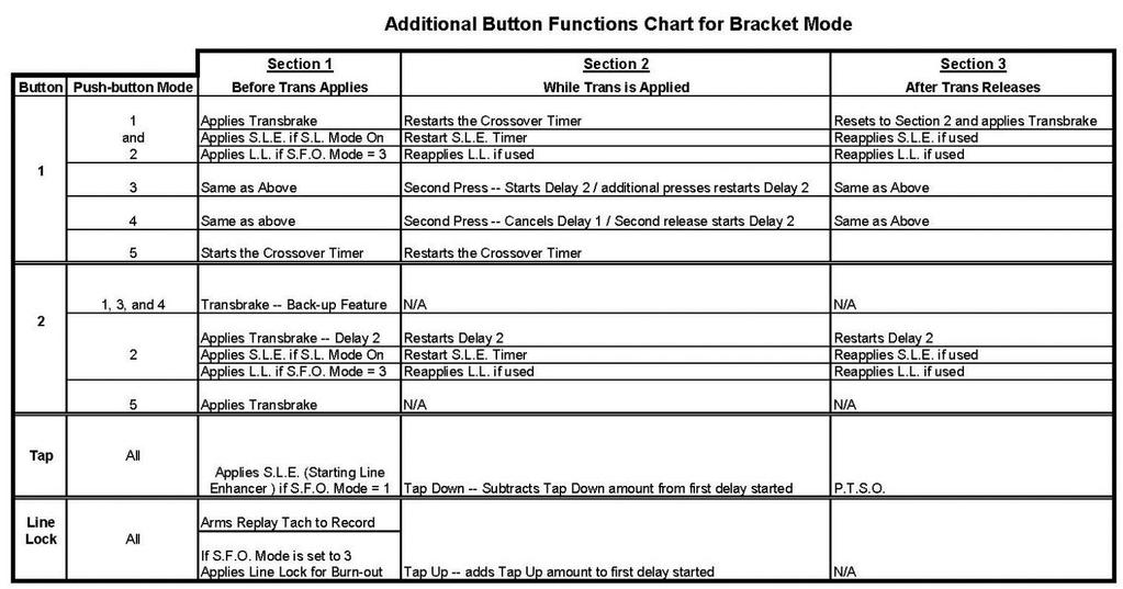
49 The Push-button Inputs The buttons are used to start all timing sequences of the Mega 475. There are four push-button inputs, labeled P.B. 1, P.B. 2, Tap P.B., and L.L. P.B. The P.B. 1 terminal is the primary button input and must be connected, for the Mega 475 to work. Most buttons have more than one purpose, the Additional Button Functions Chart on page 55 shows the primary function along with any other functions for each of the buttons. What the primary, second, and third function of each button is, depends on whether the Mega 475 is in Bracket or Pro Mode and what the Push-button Mode is. Each button is listed below individually to explain their functions depending on these conditions. Button 1 Functions Note: P.B. Mode 1 4 start timing on the release of the button. P.B. 5 is the opposite and starts timing on the press of the button. When in Bracket Mode P.B. Mode Set to 1 This is the most commonly used setting. Press the button down when staging the vehicle, and then release the button, usually on the top yellow light. When the button is released the Mega 475 will start counting down the Crossover/Delay 1 time. If the button is pressed again the countdown is terminated. Then when the button is then released again the Mega 475 will start counting down the full Crossover/Delay 1 time again. This is helpful if the driver flinches (lets go of the button before the top yellow comes on)
50 P.B. Mode Set to 2 Uses two push-buttons, one for each Delay time. With Button 1 starting the Crossover/Delay 1 time and Button 2 starting the Delay 2 time. The main benefit of this setting is, it allows two shots at the tree, in case you missed the tree with your first release. Also if the driver flinches on the first hit, Button 1 can be pressed again to avoid a red light. The downside is, having to use two separate pushbuttons at the starting line is a loss of a Button input for other uses. P.B. Mode Set to 3 Allows two shots at the tree with one button, this is usually both top yellows but can be set for top and bottom on the same side of the tree. When the button is released the first time, the Crossover/Delay 1 time starts counting down. The button is then pressed and released a second time, which starts the Delay 2 time counting down. The Transbrake will release when either of the delay times reaches zero, even if this results in a red light. The main benefit of this setting is, it allows two shots at the tree using only one push-button, in case you missed the tree with your first release. The downside is you cannot reset the first delay to stop a red light if you flinch. The second press of the button switches to Delay 2 while Crossover/Delay 1 time continues counting down. P.B. Mode Set to 4 Similar to P.B. Mode 3. The main difference is that when the button is pressed the second time, the Crossover/Delay 1 time is canceled. When Button 1 is released the first time, the Crossover/Delay 1 time starts counting down. If Button 1 is then pressed a second time, the Crossover/Delay 1 time is canceled. Then when Button 1 is released a second time, Delay 2 time starts counting down
51 The Transbrake will only release on Crossover/Delay 1 if Button 1 is not pressed a second time. However if Button 1 is pressed and released a second time the Transbrake will be released when Delay 2 time reaches zero. P.B. Mode Set to 5 This mode requires two buttons to operate the Transbrake. If the Transbrake has not already been activated pressing Button 1 has no effect. If the Transbrake has been set, pressing the button down, usually on the top yellow light, starts the counting down of the Crossover/Delay 1 time. If the button is pressed again the Mega 475 will start counting down the full Crossover/Delay 1 time again. This is helpful if the driver flinches (presses the button before the top yellow comes on). When in Pro Mode P.B. Mode is set to 1, 2, 3, or 4 When the P.B. mode is set to 1, 2, 3, or 4 the Mega 475 will automatically use P.B. Mode 1 for Pro mode. This is because P.B. modes 2, 3, and 4 won t work with a Pro Tree. Press the button down when staging the vehicle, and then release the button when the three yellow lights come on. When the button is released the Mega 475 will start counting down the Pro Delay time. P.B. Mode Set to 5 This mode requires two buttons to operate the Transbrake. If the Transbrake has not already been activated pressing Button 1 has no effect. If the Transbrake has been set, when the three yellow lights on the tree come on, press the button to start the countdown of the Pro Delay time
52 Button 2 When in Bracket Mode P.B. Mode is Set to 2 Button 2 is only used to activate Delay 2. Each time Button 2 is pressed the Transbrake solenoid is engaged and the Delay 2 time value is loaded into a counter. When the button is then released the counter starts timing down. When the counter reaches zero the Transbrake solenoid is released. P.B. Mode is Set to 1,3, or 4 The first function for Button 2 is to be the back-up button. This feature is used by vehicles that require the Transbrake solenoid to be engaged to back-up. The back-up feature is explained on page 62. There is no second or third function for Button 2 in Bracket Mode. P.B. Mode is Set to 5 The first function for Button 2 is to set the Transbrake solenoid. When the button is pressed the Transbrake will engage, however on the release of the button the timing is started. There is no second or third function for Button 2 in Bracket Mode. When in Pro Mode P.B. Mode is Set to 1, 2, 3, or 4 The first function for Button 2 is to be the back-up button. This feature is used by vehicles that require the Transbrake solenoid to be engaged to back-up. The back-up feature is explained on page 62. There is no second or third function for Button 2 in Pro Mode
53 P.B. Mode is Set to 5 The first function for Button 2 is to set the Transbrake solenoid. When the button is pressed the Transbrake will engage, however on the release of the button the timing is started. There is no second or third function for Button 2 in Pro Mode. Tap Button Settings When in Bracket Mode Any P.B. Mode The first function for the Tap button is to set the S.L.E. so the vehicle can be staged with the gas pedal fully depressed. The S.L.E. feature is explained on page 33. The second function for the Tap button is to Tap Down, allowing time to be subtracted from the first delay started. The Tap Down feature is explained on page 28. The third function for the Tap button is to activate the P.T.S.O., a Timer 1 Tap feature. The P.T.S.O. feature is explained on page 35. When in Pro Mode Any P.B. Mode The first function for the Tap button is to set the S.L.E. so the vehicle can be staged with the gas pedal fully depressed. The S.L.E. feature is explained on page 33. The second function for the Tap button is to activate the P.T.S.O., a Timer 1 Tap feature. The P.T.S.O. feature is explained on page 35. There is no third function for the Tap button in Pro Mode
54 Line Lock Button Settings When in Bracket Mode Any P.B. Mode The first function for the Line Lock button is to activate the Line Lock solenoid(s) for a burn-out. This also arms the Replay Tach at the same time. The second function for Line Lock button is Tap Up, allowing time to be added to the first delay started. The Tap Up feature is explained on page 27. There is no third function for the Line Lock button in Bracket Mode. When in Pro Mode Any P.B. Mode The first function for the Line Lock button is to activate the Line Lock solenoid(s) for a burn-out. This also arms the Replay Tach at the same time. There is no second or third function for the Line Lock button in Pro Mode
55 - 55 -
ELITE 625 With Dial Display Control
 www.racedigitaldelay.com ELITE 625 With Dial Display Control Instruction Manual - 1 - The ELITE 625 From DIGITAL DELAY 2036 Fillmore Street Davenport Iowa 52804 563-324-1046 www.racedigitaldelay.com Congratulations
ELITE 600
 www.racedigitaldelay.com ELITE 600 Instruction Manual - 1 - The ELITE 600 From DIGITAL DELAY 2036 Fillmore Street Davenport Iowa 52804 563-324-1046 www.racedigitaldelay.com Congratulations on your purchase
ELITE 700
 www.racedigitaldelay.com ELITE 700 Instruction Manual - 1 - The ELITE 700 From DIGITAL DELAY 2036 Fillmore Street Davenport Iowa 52804 563-324-1046 www.racedigitaldelay.com Congratulations on your purchase
WARRANTY AND DISCLAIMER
 MEGA 100/200 WARRANTY AND DISCLAIMER DIGITAL DELAY INC. WARRANTS THE PRODUCTS IT MANUFACTURES AGAINST DEFECTS IN MATERIALS AND WORKMANSHIP FOR A PERIOD LIMITED TO 1 YEAR FROM THE DATE OF SHIPMENT, PROVIDED
1014-CTC WARRANTY AND DISCLAIMER
 2036 Fillmore Street Davenport, Ia. 52804 563-324-1046 www.racedigitaldelay.com 1014-CTC WARRANTY AND DISCLAIMER DIGITAL DELAY INC. WARRANTS THE PRODUCTS IT MANUFACTURES AGAINST DEFECTS IN MATERIALS AND
1014-SCR WARRANTY AND DISCLAIMER Fillmore Street Davenport, Ia
 2036 Fillmore Street Davenport, Ia. 52804 563-324-1046 www.racedigitaldelay.com 1014-SCR WARRANTY AND DISCLAIMER DIGITAL DELAY INC. WARRANTS THE PRODUCTS IT MANUFACTURES AGAINST DEFECTS IN MATERIALS AND
Digital Trim. Part # 1037 WARRANTY AND DISCLAIMER
 2036 Fillmore Street Davenport, Ia. 52804 563-324-1046 www.racedigitaldelay.com Digital Trim Part # 1037 WARRANTY AND DISCLAIMER DIGITAL DELAY ELECTRONICS INC. WARRANTS THE PRODUCTS IT MANUFACTURES AGAINST
Crossover WARRANTY AND DISCLAIMER
 2036 Fillmore Street Davenport, Ia. 52804 563-324-1046 www.racedigitaldelay.com Crossover WARRANTY AND DISCLAIMER DIGITAL DELAY INC. WARRANTS THE PRODUCTS IT MANUFACTURES AGAINST DEFECTS IN MATERIALS AND
INSTALLATION AND OPERATING MANUAL
 PRO-CUBE INSTALLATION AND OPERATING MANUAL Congratulations on your purchase of the most advanced combination delay box/timer unit available for today s precision drag racing. The PRO-CUBE has been designed
INSTALLATION AND OPERATING INSTRUCTIONS
 PRO-CUBE INSTALLATION AND OPERATING INSTRUCTIONS Congratulations on your purchase of the most advanced combination delay box/timer unit available for today s precision drag racing. The new PRO-CUBE is
INSTALLATION INSTRUCTIONS 5" SINGLE CHANNEL ULTIMATE TACH
 Instr. No. 2650-887D INSTALLATION INSTRUCTIONS 5" SINGLE CHANNEL ULTIMATE TACH IMPORTANT WEAR SAFETY GLASSES 5 4 6 COPYRIGHT PATENT PENDING 3 7 8 PLAYBACK 9 2 0 1 AUTO METER PRODUCTS, INC. SYCAMORE, IL
K+R Performance Engineering, Inc.
 INSTALLATI AND OPERATING MANUAL FOR MODELS XBC-100 and XTC-200 WITH BUMP-DOWN INTRODUCTI The XBC-100 and XTC-200 units have been designed to give you ultimate control of your reaction time and ET with
Z Force is a patented concept for reacting to the tree. ZERO force required on transbrake
 PRO-CUBE Z-PLUS INSTALLATION AND OPERATING INSTRUCTIONS Congratulations on your purchase of the most advanced combination delay box/timer unit available for today s precision drag racing. The new PRO-CUBE
PRO-COMP/PHANTOM TACH
 2650-895B INSTALLATION INSTRUCTIONS 5 single channel PRO-COMP/PHANTOM TACH COPYRIGHT PATENT 5 4 6 3 PENDING 7 8 PLAYBACK 9 2 0 1 AUTO METER PRODUCTS, INC. SYCAMORE, IL USA MADE RPM x 1000 IN USA MENU SELECT
FOR SERVICE SEND TO: AUTO METER PRODUCTS, INC. 413 W. Elm St., Sycamore, IL USA (815) us at
 us at") 2650-887F INSTALLATION INSTRUCTIONS 5 single channel ultimate tach COPYRIGHT PATENT 5 4 6 3 PENDING 7 8 PLAYBACK 9 2 0 1 AUTO METER PRODUCTS, INC. SYCAMORE, IL USA MADE R P M X1000 IN USA ENTER START PAUSE
2650-887F INSTALLATION INSTRUCTIONS 5 single channel ultimate tach COPYRIGHT PATENT 5 4 6 3 PENDING 7 8 PLAYBACK 9 2 0 1 AUTO METER PRODUCTS, INC. SYCAMORE, IL USA MADE R P M X1000 IN USA ENTER START PAUSE
INSTALLATION AND OPERATING INSTRUCTIONS
 PRO-CUBE II INSTALLATION AND OPERATING INSTRUCTIONS Congratulations on your purchase of the most advanced combination delay box/timer unit available for today s precision drag racing. The new PRO-CUBE
Caution! Caution! Air/CO2 and Electric Shift Devices
 Caution! Caution! Air/CO and Electric Shift Devices You must set rpm in the CHEETAH E-SHIFT Controller before starting vehicle! Failure to do this could cause injury and or property damage! Read Instructions
MODEL MCL-3212 SPEEDOMETER/TACHOMETER for 2012 up Dyna and Softail with 4 gauge
 MODEL MCL-3212 SPEEDOMETER/TACHOMETER for 2012 up Dyna and Softail with 4 gauge IMPORTANT NOTE! This gauge has an odometer preset option that is only available one time in the first 100 miles (160km) of
SCHNITZ MOTORSPORTS PNC-202, 2-STAGE PROGRESSIVE NITROUS CONTROLLER USER MANUAL AND INSTALLATION GUIDE NOS PULSE FREQUENCY
 SCHNITZ MOTORSPORTS PNC-202, 2-STAGE PROGRESSIVE NITROUS CONTROLLER USER MANUAL AND INSTALLATION GUIDE NOS #2, FUEL SOLENOID(GROUND) 1GA PURPLE, PAGE 14 NOS #2 NITROUS SOLENOID(GROUND) 1GA PURPLE, PAGE
MODEL MCL /8 SPEEDOMETER/TACHOMETER for 2004 up
 MODEL MCL-3204 3-3/8 SPEEDOMETER/TACHOMETER for 2004 up IMPORTANT NOTE! This gauge has an odometer preset option that is only available one time in the first 100 miles (160km) of operation. See Odometer
Maximiser Progressive Controller
 Maximiser Progressive Controller Street & Race Model Owner's Manual 44 (0) 01302 834343 www.noswizard.com Introduction Congratulations on purchasing the Maximiser for the ultimate in progressive nitrous
Lingenfelter NCC-002 Nitrous Control Center Quick Setup Guide
 Introduction: Lingenfelter NCC-002 Nitrous Control Center Quick Setup Guide The NCC-002 is capable of controlling two stages of progressive nitrous and fuel. If the NCC-002 is configured only for nitrous,
TranZformer 2 nd Gen Shift Kit Installation
 TranZformer 2 nd Gen Shift Kit Installation For Firmware Version 2.0.0-061214 The TranZformer Shift Kit is an electronic shift enhancer for 2011-2014 Dodge Charger and Chrysler 300 vehicles. The TranZformer
OPERATING INSTRUCTIONS
 LCPRO-3 and LCPRO-4 LOW CURRENT REMOTE START SYSTEM OPERATING INSTRUCTIONS CONGRATULATIONS on your choice of a PRO Start Remote Engine Starter and Keyless Entry by Crimestopper Security Products Inc. This
Model AS-9234E. Owners Guides
 Model AS-9234E Owners Guides This unit is capable of 3 installation methods. Select the guide for your customer that matches the installation in their particular vehicle. PATENTED: www.voxxintlcorp.com/company/patents
REMOVAL OF FACTORY GAUGE ULTRA FLHT & FLHX (STREET GLIDE
 MCL-36K-SPD Thank you for purchasing the Dakota Digital MCL-36K-SPD gauge for your Harley Davidson Touring bike. This kit is designed to be a direct, plug in replacement for all touring models from 2004
Automotive Application ET01 Software Revision A 12/06
 Automotive Application ET01 Software Revision A 12/06 INTRODUCTION... 2 FUNCTIONAL DESCRIPTION... 3 INSTALLATION... 4 COMPONENT PLACEMENT... 4 PLUMBING AND WIRING... 5 MSBC OPERATION (ET-01)... 14 TIMED
Product Overview. Shift light turns on when RPM is above programmed shift point. Stage 2 activation light turns on when Stage 2 is active.
 These instructions will guide you through the setup, installation, and use of the Nitrous Outlet WinMax Window Switch. If you have any questions about the WinMax, please call our Tech Help Line at (254)
INSTALLATION GUIDE. FCC ID NOTICE
 REV.5 RS. ADVANCED REMOTE STARTER INSTALLATION GUIDE www.security.soundstream.com FCC ID NOTICE This device complies with Part 5 of the FCC rules. Operation is subject to the following conditions:. This
NOS -36 Magic. An electronic timer for E-36 and F1S Class free flight model aircraft. January This document is for timer version 2.
 NOS -36 Magic An electronic timer for E-36 and F1S Class free flight model aircraft January 2017 This document is for timer version 2.0 Magic Timers Copyright Roger Morrell January 2017 January 2017 Page
Idle Timer Controller - ITC Freightliner MT45 Contact InterMotive for additional vehicle applications
 An ISO 9001:2008 Registered Company System Operation Idle Timer Controller - ITC805 2013-2018 Freightliner MT45 Contact InterMotive for additional vehicle applications The ITC805 system shuts down idling
AL-1670-B RS-375-3DB RS-375-3D RS-370
 REMOTE START & SECURITY PERFECTED AL-1670-B RS-375-3DB RS-375-3D RS-370 OPERATION GUIDE Temporary cover. Final cover is in a separate file. 1 Table Of Contents Controller Overview... 3 The Controller...
OPERATING INSTRUCTIONS
 EZ-1 ONE BUTTON REMOTE START SYSTEM OPERATING INSTRUCTIONS CONGRATULATIONS on your choice of a Cool Start Remote Engine Starter and Keyless Entry with DP Technology by Crimestopper Security Products Inc.
POLARSTART PS-3025 SH Multi-Channel Remote Starter System for AUTOMATIC Transmissions
 POLARSTART PS-3025 SH Multi-Channel Remote Starter System for AUTOMATIC Transmissions USER GUIDE INTRODUCTION...2 BASIC REMOTE OPERATION...2 REMOTE-STARTING YOUR VEHICLE...2 DRIVING OFF...2 IDLE MODE...2
RR Concepts. The StationMaster can control DC trains or DCC equipped trains set to linear mode.
 Jan, 0 S RR Concepts M tation aster - 5 Train Controller - V software This manual contains detailed hookup and programming instructions for the StationMaster train controller available in a AMP or 0AMP
MSD 7AL-3, Ignition Control PN 7230
 MSD 7AL-3, Ignition Control PN 7230 Important: Read the instructions before attempting the installation. Parts Included: 1-7AL-3, PN 7230 1 - Parts bag (wires and connectors) 4 - RPM Modules 3000, 7000,
Quick-Kill Installation Manual V1.0 (Universal Motorcycle Application)
") Quick-Kill Installation Manual V1.0 (Universal Motorcycle Application) THIS INSTALLATION MANUAL IS FOR UNIVERSAL FUEL INJECTED MOTORCYCLE APPLICATIONS (NON PLUG AND PLAY), WITH OR WITHOUT A GEAR POSITION
Quick-Kill Installation Manual V1.0 (Universal Motorcycle Application) THIS INSTALLATION MANUAL IS FOR UNIVERSAL FUEL INJECTED MOTORCYCLE APPLICATIONS (NON PLUG AND PLAY), WITH OR WITHOUT A GEAR POSITION
ELECTRONIC TRACTION CONTROL USER MANUAL
 DRAG-SPORTSMAN N2O For ELECTRONIC TRACTION CONTROL USER MANUAL TELEPHONE 828.645.1505 FAX 828.645.1525 WWW.MORETRACTION.COM US PATENT 6,577,944 Disclaimer...2 Introduction... 3 How Does It Work. 4 Installation...
DRIVE MODE SUPPLEMENT
 DRIVE MODE SUPPLEMENT DRIVE MODE SUPPLEMENT DODGE DRIVE MODES...3 SRT DRIVE MODES...33 DODGE DRIVE MODES SECTION TABLE OF CONTENTS PAGE 1 UNDERSTANDING YOUR INSTRUMENT PANEL...7 1 UNDERSTANDING YOUR
THROTTLE & RPM-ACTIVATED NITROUS CONTROL SYSTEM P/N 15970NOS
 THROTTLE & RPM-ACTIVATED NITROUS CONTROL SYSTEM P/N 15970NOS Installation Instructions 199R10300 INTRODUCTION: Congratulations on the purchase of your NOS throttle and RPM-activated nitrous control system!
L I M I T E D L I F E T I M E W A R R A N T Y
 L I M I T E D L I F E T I M E W A R R A N T Y Products manufactured and sold by OMEGA RESEARCH & DEVELOPMENT, INC. (the Company), are warranted to be free from defects in materials and workmanship under
ECT Display Driver Installation for AP2 Module
 ECT Display Driver Installation for AP2 Module Overview The ECT Display Driver is a small module with a removable wire harness that mounts behind the driver's foot well cover. All wiring connections are
Setup and Programming Manual
 Microprocessor and Handy Terminal Setup and Programming Manual Versions U04 to U19 for Sliding Door Systems P/N 159000 Rev 7-2-07 The manufacturer, NABCO Entrances, Inc. suggests that this manual be given
12V PROGRAMMABLE POWER OUT
 Page 1 ACCESSORIES STARTER IGNITION BATTERY WIRES SIDE VIEW BLUE RED YELLOW 30 A 10 A BLUE / WHITE YELLOW WHITE / BLUE WHITE / DOOR TRIGGER See opt. 16 DOOR TRIGGER (input positive) See opt. 16 PARKING
RS-330-EDP. Operation Guide
 RS-330-EDP Deluxe Keyless Entry & Remote Start Operation Guide July 26, 2010 Temporary cover. Color cover is in a separate file. Table Of Contents Introduction... 3 The Transmitter... 4 Transmitter Functions
RS-230-DP. Operation Guide
 RS-230-DP Deluxe Keyless Entry & Remote Start July 27, 2010 Operation Guide Temporary cover. Color cover is in a separate file. Table Of Contents Introduction...2 The Transmitter...3 Transmitter Functions...3
TWO-WAY LED MANUAL / AUTOMATIC TRANSMISSION REMOTE STARTER. User Guide WARNING
 TWO-WAY LED MANUAL / AUTOMATIC TRANSMISSION REMOTE STARTER User Guide WARNING It is the responsibility of the vehicle operator to ensure their vehicle is parked in a safe and responsible manner. 1. a)
REVISION HISTORY REVISION HISTORY
 FILTER CONTROLLER REVISION HISTORY Filter Flush Controller forms part of the Netafim range of filtration controllers all designed to make filteration more reliable and economical.. Contact any of the Netafim
Tazer 2 nd Gen Unlocker & Line Lock For Firmware Version
 Tazer 2 nd Gen Unlocker & Line Lock For Firmware Version 2.1.8-091715 The Tazer is an electronic plug-in device for 2011-2015 Dodge Charger, Chrysler 300, 2015 Dodge Challenger, Durango and Jeep Grand
INSTALLATION GUIDE Table of Contents
 CT-3100 Automatic transmission remote engine starter systems. What s included..2 INSTALLATION GUIDE Table of Contents Door lock toggle mode..... 4 Notice...2 Installation points to remember. 2 Features..2
USER MANUAL AND INSTALLATION GUIDE ENGINE RPM AND NOS SHIFT COUNTER NOS DELAY TIME IN SECONDS NOS START PERCENT NOS FINAL PERCENT
 SCHNITZ MOTORSPORTS DSC-9PS "PRO-STREET" IGNITION CONTROLLER USER MANUAL AND INSTALLATION GUIDE SHIFT LIGHT POSITIVE PAGE 2 SHIFT LIGHT GROUND PAGE 2 NOS SOLENOID GROUND 1GA ORANGE, FUEL SOLENOID GROUND
HP21 SERVICE SUPPLEMENT UNIT INFORMATION. TSC6 Two-Speed Control
 SERVICE UNIT INFORMATION SUPPLEMENT HP21 Corp. 9426 L10 Litho U.S.A. All HP21-4 and -5 units (single and three phase) are equipped with a TSC6 two-speed control. The TSC6 (A14) two-speed control contains
BSR Magic Box Digital ignition control for 4, 6, or 8 cylinder engines
 BSR BSR Magic Box Digital ignition control for 4, 6, or 8 cylinder engines Features Digital Advance The main feature of the Magic Box is the digital advance that replaces conventional weights and springs.
BigStuff3 - GEN3. 1st Gear Spark Retard with Spark Retard Traction Control System (SR 2 ) Rev
 Rev") BigStuff3 - GEN3 1st Gear Spark Retard with Spark Retard Traction Control System (SR 2 ) 12-09 System Description 1st Gear Spark Retard with Spark Retard Traction Control System (SR 2 ) - SR 2 uses two
BigStuff3 - GEN3 1st Gear Spark Retard with Spark Retard Traction Control System (SR 2 ) 12-09 System Description 1st Gear Spark Retard with Spark Retard Traction Control System (SR 2 ) - SR 2 uses two
TIP SHEET T0937. Installation Tips For RS00/PS00 + ADS-TBSL-PL + SPDT
 Installation Tips For RS00/PS00 + ADS-TBSL-PL + SPDT TIP SHEET T0937 Thank you for purchasing your remote start from MyPushcart.com - an industry leader in providing remote starts to do-it-yourself installers
Nemesis-TCS system manual release /11/2011 Author Mick Boasman. UK Tel
 Nemesis-TCS Traction Control System Firmware TCS 2 cylinder 1.21 onwards Firmware TCS 4 cylinder 1.08 onwards TC-Pod 1.05 WinTC Software 1.11 -User Onwards 2 cylinder WinTC Software 2.04 -User Onwards
TWO-WAY LCD AUTOMATIC TRANSMISSION REMOTE STARTER. User Guide
 TWO-WAY LCD AUTOMATIC TRANSMISSION REMOTE STARTER User Guide A note concerning the battery inside the transmitter: Depending on your usage of the transmitter, the battery can last anywhere between 3 to
The GearMaster II. Making Shifting a Breeze
 The GearMaster II Making Shifting a Breeze Congratulations on your purchase of the GearMaster, the world s first and only Gear Availability and Synchronization Indicator! You will find that the GearMaster
MCL-30K-SPD IMPORTANT NOTE!
 MCL-30K-SPD Thank you for purchasing the Dakota Digital MCL-30K-SPD gauge for your Harley Davidson Touring bike. This is designed to be a replacement for all touring models from 1996 2003. This is part
TWO-WAY LED MANUAL TRANSMISSION REMOTE STARTER. User Guide WARNING
 TWO-WAY LED MANUAL TRANSMISSION REMOTE STARTER User Guide WARNING It is the responsibility of the vehicle operator to ensure their vehicle is parked in a safe and responsible manner. 1. When leaving the
Smart Wi-Fi Sprinkler Timer and Flow Meters
 Smart Wi-Fi Sprinkler Timer and Flow Meters User s Manual Welcome to H2OPro Thank you for purchasing the H2OPro. The H2OPro is a sprinkler timer with a Wi-Fi interface. The system provides sprinkler valve
GLM SERIES CONTROL Users Manual Rev:
 GLM SERIES CONTROL Users Manual Rev: 808062 Connecting Power Page 2 Motor Terminal Wiring Diagrams Page 3 Getting Started / Setup Page 4 1. Obstruction Detection Devices Page 4 2. Checking Power and Direction
AS-4000 OPERATING INSTRUCTIONS (PS-5000)
") AS-4000 OPERATING INSTRUCTIONS (PS-5000) BASIC OPERATIONS This unit is a state-of-the-art combination of a vehicle alarm and remote starter system. Start by familiarizing yourself with the alarm functions
AS-4000 OPERATING INSTRUCTIONS (PS-5000) BASIC OPERATIONS This unit is a state-of-the-art combination of a vehicle alarm and remote starter system. Start by familiarizing yourself with the alarm functions
MODEL MVX-2011 TANK MOUNT SPEEDOMETER/TACHOMETER
 MODEL MVX-2011 TANK MOUNT SPEEDOMETER/TACHOMETER Wiring Diagram The MVX-2011 gauges will work on 2011-up Softail models with 5 gauges or 2012-up Dyna models with 5 gauges. It is a direct plug in on these
OPERATING INSTRUCTIONS
 DS7 2-WAY REMOTE START SYSTEM OPERATING INSTRUCTIONS CONGRATULATIONS on your choice of a Data Start Remote Engine Starter and Keyless Entry by Crimestopper Security Products Inc. This system is designed
OPERATING INSTRUCTIONS
 LCPRO-7 2-WAY REMOTE START SYSTEM OPERATING INSTRUCTIONS CONGRATULATIONS on your choice of a PRO Start Remote Engine Starter and Keyless Entry by Crimestopper Security Products Inc. This system is designed
3200ET TIMER. Service Manual. IMPORTANT: Fill in pertinent information on page 2 for future reference.
 3200ET TIMER Service Manual IMPORTANT: Fill in pertinent information on page 2 for future reference. Installation And Start-Up Procedures Timer Programming Water Hardness System Capacity Regeneration Time
533i 3 OPERATION MANUAL TABLE OF CONTENTS
 TABLE OF CONTENTS OPERATION MANUAL 533i 3 COPYRIGHT 1999: OMEGA RESEARCH & DEVELOPMENT, INC. About Your New Crime Guard System... 3 Using Your Crime Guard System... 4 Remote Arming By Transmitter... 4-5
AL-1660-EDPB RS-360-EDPB. Deluxe Alarm & Remote Start w/ BLADE Technology. April 23, Operation Guide
 AL-1660-EDPB RS-360-EDPB Deluxe Alarm & Remote Start w/ BLADE Technology April 23, 2015 Operation Guide Temporary cover. Color cover is in a separate file. 1 Table Of Contents Transmitter Overview... 3
Model AS-9234 Owners Guide Upgrade Vehicle Security & Remote Start System
 Table Of Contents: Model AS-9234 Owners Guide Upgrade Vehicle Security & Remote Start System Features Options Page 2 Page 2 Arming the System - Active Page 3 Arming the System - Passive (Automatic) Page
Lingenfelter TMR-001 Timer Delay Control Module
 Lingenfelter TMR-001 Timer Delay Control Module PN: L460290000 Revision - 1.1 Lingenfelter Performance Engineering 1557 Winchester Road Decatur, IN 46733 (260) 724-2552 (260) 724-8761 fax www.lingenfelter.com
RF-51-eDp. Operation guide. Deluxe 2-way Oem Upgrade & Range extender. July 22, 2014
 RF-51-eDp Deluxe 2-way Oem Upgrade & Range extender July 22, 2014 Operation guide Man nuales En Español Table Of Contents Controller & Transmitter Overview... 3 The 2-Way Controller... 3 The 1-Way Transmitter...
TWO-WAY LED AUTOMATIC TRANSMISSION REMOTE STARTER. User Guide WARNING
 TWO-WAY LED AUTOMATIC TRANSMISSION REMOTE STARTER User Guide WARNING It is the responsibility of the vehicle operator to ensure their vehicle is parked in a safe and responsible manner. 1. When leaving
User Guide TWO-WAY LED AUTOMATIC/MANUAL TRANSMISSION REMOTE STARTER WITH FULL ALARM SYSTEM
 TWO-WAY LED AUTOMATIC/MANUAL TRANSMISSION REMOTE STARTER WITH FULL ALARM SYSTEM User Guide WARNING It is the responsibility of the vehicle operator to ensure their vehicle is parked in a safe and responsible
2 WAY REMOTE STARTER & ALARM SYSTEM INSTALLATION GUIDE FCC ID NOTICE
 REV. ARS. WAY REMOTE STARTER & ALARM SYSTEM INSTALLATION GUIDE FCC ID NOTICE This device complies with Part 5 of the FCC rules. Operation is subject to the following conditions:. This device may not cause
MAX-FIRE AND E-FIRE ELECTRONIC DISTRIBUTORS
 INSTALLATION INSTRUCTIONS MAX-FIRE AND E-FIRE ELECTRONIC DISTRIBUTORS NOTE: This product is applicable to pre-1966 California and pre-1968 federally certified passenger cars. It is also applicable to non-emission
Vehicle Reaction Timer Instructions
 Vehicle Reaction Timer Instructions The Computech Systems Vehicle Reaction Timer is designed to very accurately measure the time from when your vehicle is instructed to launch to when it actually begins
Flight Systems. Replacement for KASSEC DESCRIPTION
 DESCRIPTION The is a universal generator controller that will start, stop, and provide engine protection for most generators. Universal replacement for both the 90353 and 90354 KASSEC Compatible with most
MCL-3014 gauge kit. Optional Readings: Boost Pressure with MBM-09, Front or Rear Air Suspension Pressure with MBM-19
 MCL-3014 gauge kit Thank you for purchasing the Dakota Digital MCL gauge kit for your Harley Davidson Touring bike. This kit is designed to be a direct plug in replacement for all touring models from 2014
Thank you for your purchase Off-ROad NOtice: PROduct WaRNiNgs:
 Thank you for your purchase. Please, read the instructions and watch the video before installing the JMS Progressive N20 Controller. Configuration and installation videos are available online: www.jms-nos.com.
AL-100DP Full-Feature Vehicle Security System for Factory-Equipped Remote Keyless Entry Transmitters Owner s Guide
 This device complies with FCC Rules part 15. Operation is subject to the following two conditions, (1) This device may not cause harmful interference and, (2) This device must accept any interference that
ECHO Enhanced Controller Hook Count Application *** Infrared Photo Sensors *** GCA 110 ECHO Controller. Version 3.5
 ECHO Enhanced Controller Hook Count Application *** Infrared Photo Sensors *** GCA 110 ECHO Controller Version 3.5 1 Change History: Feb 01, 2005 Mar 16, 2005 May 22, 2005 May 9, 2006 By request from CCS,
Model SS6900 Owner s Manual of 12
 Model SS6900 Owner s Manual 7 Channel Long Range Remote Car Starter FEATURES: 1 Five Button Programmable Spread Spectrum RF Transmitter 1 Five Button Programmable Spread Spectrum RF LCD Transceiver Seven
EQUIPMENT - MAIN BODY 7-1 SECTION 7 EQUIPMENT CONTENTS
 EQUIPMENT - MAIN BODY 7-1 SECTION 7 EQUIPMENT CONTENTS Engine Immobiliser System...7-1 Exterior Lights...7-2 Combination Meter...7-2 Smart Wiring System (SWS)...7-3 General Information...7-3 Functions
DRIVE MODE SUPPLEMENT
 DRIVE MODE SUPPLEMENT DRIVE MODE SUPPLEMENT DODGE DRIVE MODES...3 SRT DRIVE MODES...29 DODGE DRIVE MODES SECTION TABLE OF CONTENTS PAGE 1 UNDERSTANDING YOUR INSTRUMENT PANEL...7 UNDERSTANDING YOUR INSTRUMENT
Register at caralarm.com OPERATION GUIDE AL DB RS-475-3D. al db & rs-475-3d op guide.indd 1
 Register at caralarm.com OPERATION GUIDE AL-1775-3DB RS-475-3D al-1775-3db & rs-475-3d op guide.indd 1 8/3/16 7:41 AM REMOTE START & SECURITY PERFECTED AL-1775-3DB / RS-475-3D OPERATION GUIDE Temporary
Model PRO-9276a Owner s Manual
 Model PRO-9276a Owner s Manual 7 Channel Remote Car Starter FEATURES : 2 Five Button Programmable RF Transmitters Seven Channel Receiver (capable of accepting 4 transmitters) Code Hopping Technology Combination
PCS HIGH-LOW TIMER CONTROLLER USER GUIDE PCS HIGH-LOW TIMER CONTROLLER. Contents. Calibrating the Transducer... 6
 PCS HIGH-LOW TIMER CONTROLLER Contents Basic Operations... Controller s Faceplate... Turning the Controller On and Off... Status Display... Program Function and Report Reference... 3 Program Functions...
Begin to Use The New ESC: Before use the new ESC please carefully check every connections are correct or not. Yellow motor wire B Blue motor wire A
 HIMOTO ZTW Brushless Electronic Speed Control for car or truck Thank you for purchasing ZTW Brushless Electronic Speed Controller(ESC). The ZTW electronic speed control (ESC) is specifically designed for
OPERATING MANUAL Digital Diesel Control Remote control panel for WhisperPower generator sets
 Art. nr. 40200261 OPERATING MANUAL Digital Diesel Control Remote control panel for WhisperPower generator sets WHISPERPOWER BV Kelvinlaan 82 9207 JB Drachten Netherlands Tel.: +31-512-571550 Fax.: +31-512-571599
OPERATING INSTRUCTIONS RS900ER/RS901 SERIES I
 OPERATING INSTRUCTIONS RS900ER/RS901 SERIES I INTRODUCTION CONGRATULATIONS on your choice of a CoolStart Remote Engine Starter by Crimestopper Security Products Inc. This system is the most advanced and
ICL Three Pump Controller
 ICL Three Pump Controller Pump Operation The number of pumps that the program controls can be selected by enabling only the ones that are currently installed and in service. The enable/disable setting
HIGH TECH SECURES YOUR FUTURE SBA 1200 GB SUN BRAKE ANALYSER. Operating Manual
 HIGH TECH SECURES YOUR FUTURE SUN BRAKE ANALYSER Operating Manual 2 Operating Manual SUN BRAKE ANALYSER Copyright December 2009 Snap-on Equipment GmbH All rights reserved Part number: 2000618380 Rev: 3
MODEL MCL-2004(-R) TANK MOUNT SPEEDOMETER/TACHOMETER
 TANK MOUNT SPEEDOMETER/TACHOMETER") MODEL MCL-2004(-R) TANK MOUNT SPEEDOMETER/TACHOMETER Wiring Diagram The MCL-2004(-R) gauges will work on 2004-2011 models except 2011 Softail. It is a direct plug in on these models and requires no additional
MODEL MCL-2004(-R) TANK MOUNT SPEEDOMETER/TACHOMETER Wiring Diagram The MCL-2004(-R) gauges will work on 2004-2011 models except 2011 Softail. It is a direct plug in on these models and requires no additional
Model PRO-9675FT4 Owner's Manual
 Model PRO-9675FT4 Owner's Manual 4 Button Remote Start Security System With Plug-In Shock Sensor & Starter Disable FEATURES : w 2 Four Button Programmable RF Transmitters w Four Channel Code Learning Receiver
INSTRUCTIONS. #82028 Diesel Nitrous System. Thank you for choosing ZEX products; we are proud to be your manufacturer of choice.
 1 INSTRUCTIONS #82028 Diesel Nitrous System Thank you for choosing ZEX products; we are proud to be your manufacturer of choice. Why our nitrous system is better: 2 Performance enthusiasts know the potential
Only use if safe to do so and at your own risk.
 This product may not be suitable or safe for road usage. The owner accepts ALL responsibility for its use and installation. The product must not be used if malfunction occurs, a suspected malfunction occurs
Model PRO-9775T Owner's Manual 4 Button Remote Start Security System With Plug-In Shock Sensor & Starter Disable
 Model PRO-9775T Owner's Manual 4 Button Remote Start Security System With Plug-In Shock Sensor & Starter Disable FEATURES:! 2 Four Button Programmable RF Transmitters! Four Channel Code Learning Receiver
CurveMaker HD v1.0 2Ki Programmable Ignition programming software
 Contents CurveMaker HD v1.0 2Ki Programmable Ignition programming software Dynatek 164 S. Valencia St. Glendora, CA 91741 phone (626)963-1669 fax (626)963-7399 page 1) Installation 1 2) Overview 1 3) Programming
UTV-1000 Multi Gauge for Yamaha Rhino
 IMPORTANT NOTE! This gauge has an hour meter and odometer preset option available only for the first 1.0 engine hour and 10 miles (16km). See ODO/HR PRESET for instructions. UTV-1000 Multi Gauge for 2004-2006