Electronic Dynamo Regulator INSTRUCTION MANUAL. COPYRIGHT 2015 CLOVER SYSTEMS All Rights Reserved
|
|
|
- Gervase Stokes
- 5 years ago
- Views:
Transcription


1 DR310 TM Electronic Dynamo Regulator INSTRUCTION MANUAL COPYRIGHT 2015 CLOVER SYSTEMS All Rights Reserved
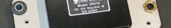
2 INTRODUCTION The Clover Systems DR310 is an allelectronic voltage and current regulator for dynamos used in vintage cars, trucks, tractors, motorcycles, and boats. It is designed to be used with Lucas dynamos, although it can work with other dynamos as well. INSTALLATION Figure 1 With Lucas Cover Figure 2 - Connections 1) First, be sure that you have the correct model DR310 for your vehicle (Positive or Negative Earth, 6 or 12 volts, and correct current limit to match your dynamo). Although DR310 is protected against most every possible problem, it is possible to damage the unit and/or your generator if for instance, the battery is hooked up backward (see below). 2) Disconnect the battery ground cable to prevent any mishaps. 3) Next, label all wires connected to your existing regulator. With RB340, the wires are (left to right, viewed from the front) D (Dynamo Armature), WL (Warning Light), F (Field Coil), B (Battery1), and B (Battery2). The two B terminals are connected together. One goes to the battery, and the other goes to the vehicle s ignition switch and lights. Since they are connected together, it doesn t matter which wire goes on which terminal DR310 Instruction Manual Pg. 1
3 If you do not already have a regulator connected, you may need to trace the wires to see exactly where they go. 4) The WL terminal is connected directly to the D terminal. If your vehicle doesn t have a warning light connection, it can be left open. On the Lucas regulator, the WL terminal is to the left of the D terminal, but on ours, it is to the right. 5) The DR310 (like the Lucas RB 310) is grounded to the chassis via the single mounting bolt. Be sure that the right hand mounting bolt is making good connection to the chassis. Ideally, you should check the connection with an ohmmeter. If the DR310 is not grounded, the dynamo output will not be properly regulated. 6) If you are installing a new generator, or your existing one is in unknown condition, you should perform some simple tests to verify that it is workable: a. With an ohm-meter, you should measure resistance of ~ 2 ohms from terminal D to ground. If the resistance is infinite, then either the wire from D to the generator is not connected, or the generator s armature is open. b. Similarly, you should measure resistance of ~ 5-6 ohms from terminal F to ground. Infinite resistance indicates the wire from terminal F to the generator s field coil is not connected, or the field coils are open. A low resistance indicates partial shorting of the field coils to ground. 7) Attach the wires to the DR310, and mount the DR310 using the three stainless steel hex cap screws provided. 8) Reconnect the battery ground. If there is excessive sparking, there may be a wiring mistake. 9) If everything seems to be in order, start the engine and observe the ammeter and ignition warning light. If everything is working correctly, the warning light should go out at around 900 RPM (depending on generator model). You should also be able to see charging of the battery on the ammeter. 10) If there is no output from the generator, and it passed the above tests, see the troubleshooting section in the appendix. 11) Installing the cover. DR310 does not include the Lucas cover. You can however, use your existing cover, or find a used one. There are two styles of RB 310 cover: One has a flange and is held by two short screws. The other has no flange and is held by two long screws. In the case of the cover with the flange, use the two #8-32 machine screws included. If yours uses the long screws, you will have to use your original screws, or let us know DR310 Instruction Manual Pg. 2
 DR310 with screw terminals comes with the screws and wire clamps, but you can also use your originals if you prefer.")
4 and we can send appropriate screws. DR310 has mounting holes for both styles of cover. 12) DR310 with screw terminals comes with the screws and wire clamps, but you can also use your originals if you prefer. Caution Although the DR310 is protected against most everything that can go wrong, there are some things that can damage the DR310 and/or your dynamo: 1) Connecting the battery backward. Be sure that you have the correct polarity regulator. If there is any doubt, check the battery connections to see which battery terminal is connected to the vehicle s chassis. 2) Reversing the D and B wires will create a direct path from the battery to the dynamo s armature, which could damage your dynamo. 3) If the F wire is shorted to the D wire (dynamo armature), the dynamo will run at full output without any voltage or current limiting. Lucas regulators and wiring are made so that you cannot connect the F wire to the WL terminal (which is connected to the D terminal). We have copied this scheme, but if your wiring is not original, it may be possible to accidentally connect the F wire to the WL terminal. 4) If the DR310 is not connected to chassis ground with the right-hand mounting bolt, the regulator will not work properly. TESTING & CALIBRATION Figure 3- DR310 with Screw Terminals The DR310 voltage and current limits are set at the factory to match your dynamo, so normally, no adjustment is required. Test and calibration results are printed at the back of this manual. You may however, wish to confirm that everything is working properly, or change the settings to accommodate your needs. Both voltage and current limit are user adjustable. In the standard configuration, Voltage limit is adjustable from 5v to 17v, and current limit is adjustable from 7A to 30A. In other configurations, current limit can be up to 55A. Adjustment to the voltage or current limit must be carried out on the car. For these adjustments, you will need an analog moving-coil voltmeter (0-20V) DR310 Instruction Manual Pg. 3

5 and/or analog moving-coil ammeter (0-40A) plus a very small flat-blade screwdriver. Note: Use only analog moving-coil voltage and current meters for these tests. Digital meters will not read correctly because of rapid variations and noise in the dynamo output. Voltage Limit Test (open circuit): 1) Remove the die-cast cover by removing the three screws from the back of the unit: Figure 4 - Cover Mounting Screws 2) Remove both wires from the B terminals, and connect them together with a clip lead. This will provide power from the battery to the vehicles electrical system so the engine can run. 3) Connect an analog voltmeter capable of measuring 0-20 volts between the B terminal of the regulator and ground. 4) Now start the engine. As you increase the engine speed, you should see an increase in the voltage on the meter. Run up the engine speed, and you should see the voltage rise with engine RPM, until it reaches it s preset limit (See the Final Test Sheet at the end of this manual for the proper voltage). 5) If necessary, adjust the voltage limit control to get the desired output voltage limit. Turn the pot clockwise to increase the limit, and counter- DR310 Instruction Manual Pg. 4

6 clockwise to lower the voltage limit. You should be able to reach the voltage limit at no more than 3000 or 4000 RPM. 6) When finished, remove the voltmeter and re-attach the wires to the B terminals. Voltage Adjust Current Adjust Figure 5 Location of Pots The correct voltage limit also depends on they type of battery. The requirements for flooded type batteries, where you can add water are different than for sealed, Maintenance Free batteries, also known as VRLA, AGM, or Gel batteries, which require a lower charging voltage. The chart below shows optimal settings for the two types of batteries. We normally set the voltage at 14.3V at 25 C for 12v dynamos, and 7.2v for 6v dynamos, which is safe for all batteries. Since there are many types and models of batteries, you may wish to consult the battery specs for the optimum charging voltage. Voltage vs. Temperature Volts Flooded VRLA C Figure 6 - Voltage vs. Temperature DR310 Instruction Manual Pg. 5
7 If the car has been running with substantial electrical load, the regulator will be hotter than ambient temperature. Therefore, it is best to perform the test with the regulator at ambient temperature. Current Limit Test: 1) With the two B wires disconnected from the DR310, and connected together, connect a 0-40A ammeter between the B terminal of the regulator and the two B wires connected together. If your vehicle is negative ground, then connect the + terminal of the ammeter to the B terminal of the regulator, and the terminal of the ammeter to the two wires. For positive ground, reverse these connections. Figure 7 - Ammeter Hookup 2) Start the engine and turn on all loads such as headlights, fans, etc. As you increase the engine RPM, you should see the current flow increase until it reaches the preset limit. You may need to add additional loads to reach the desired limit. 3) Turning clockwise increases the limit, and counter-clockwise decreases the limit. 4) When finished, remove the ammeter and re-attach the wires to the B terminals. Warning: Do not adjust the current limit higher than the rated output of your dynamo, as this may overload the generator and reduce it s life. Note: Typically, the ammeter in your vehicle only measures current to and from the battery. It does not measure the total output of the generator, which could be more. To measure total generator output, you need to connect an ammeter as described above. DR310 Instruction Manual Pg. 6
8 APPENDIX History Previous to the 1970 s, vehicles used DC generators rather than the AC alternators used today. This was due to the lack of high-power semiconductor rectifiers at the time. In order to provide adequate power without destroying the battery, some means of controlling the generator s output voltage and current is required. This was accomplished using mechanical relays. When the output voltage reaches a predetermined value, a relay opens to cut off the current to the field coils. As the voltage now drops below the threshold, the relay closes, restoring current to the field coils. The rapid opening and closing of the relay regulates the output to a preset limit. Current can be controlled in the same way, but now determined by the current draw from the generator. Regulators previous to the 60s typically did not have any current regulation. Furthermore, power is supplied only when the output of the generator is greater than a preset value (the cut-in voltage ). This prevents the battery from discharging through the armature of the generator when the output of the generator is less than the battery voltage. Although this scheme can do the job, there are some drawbacks: 1) The contacts of the relays become dirty, corroded, and burned, causing unreliable operation and failure. The contacts must periodically be cleaned, and adjusted. 2) The cut-in voltage is fixed, so that the generator must reach a fairly high voltage before it can supply any power to the battery or electrical systems. The Clover Systems DR310 works in the same way, but substitutes transistor switches for the mechanical relays. As a result, switching is cleaner and more reliable, and no cleaning or adjustment is ever required. With the DR310, power is output whenever the generator voltage is higher than the battery voltage. This typically means that useful power can be supplied at a lower RPM. DR310 also includes current limiting, which is not included in most mechanical regulators. How the regulator works All generators work by rotating a loop of wire in a magnetic field. In a dynamo, the magnetic field is created by electromagnets (field coils). Voltage and current are controlled by controlling the current to the field coils. The current through the field coils determines the strength of the magnetic field that the DR310 Instruction Manual Pg. 7
9 armature rotates in, and thus the output of the generator. In the DR310, the output voltage of the generator is compared to a precision voltage reference. When the generator output exceeds this reference, the current to the field coils is cut off. This causes the generator output to fall. When the output falls below the reference voltage, the field current is turned back on. In this way, the field current is modulated at a rate of Hz. These rapid changes are smoothed out by the inductance of the field coils, thus maintaining a constant output voltage. Current limiting is accomplished in the same way. Output current is sensed with a Hall-Effect device that detects the magnetic field created by the output current. When the output current exceeds a preset limit, the field current is turned off. Just as with the voltage regulation, the field current is modulated to maintain a constant output current. Instead of a cut-out relay, DR310 uses a MOSFET ideal diode, which is much more efficient than Schottky diodes. Power is supplied whenever the dynamo output voltage is greater than the battery voltage, rather than a pre-set voltage as in the mechanical regulator. How to polarize a new generator A dynamo uses electromagnets to generate the magnetic field for the armature to rotate in. But when starting up, there is no field current to create this magnetic field. In order to get the process started, some permanent magnetism is required to provide this field. This is provided by iron pole pieces that can be permanently magnetized. A new generator may not have the pole pieces magnetized, so there will be no output, and no field current. Also, a dynamo that has been used with a different polarity (i.e., pos gnd instead of neg gnd) will be polarized backward, and will produce a voltage of the wrong polarity. Magnetizing the pole pieces is easy: While the car is not running, connect a lead from the battery (or B terminal) to the dynamo s field coil (F) terminal for one or two seconds. Connecting them for a long period could overheat and damage the field coils. The pole pieces will now be permanently magnetized, and the dynamo will start up. If the dynamo is properly polarized, it will produce ~3 volts with the field coils disconnected. DR310 Instruction Manual Pg. 8
10 Troubleshooting In case there is no output from the dynamo, check the following: 1) D terminal is not connected to the dynamo output terminal 2) F terminal is not connected to the dynamo field terminal 3) Dynamo armature is shorted or open 4) Dynamo field coils are shorted or open 5) D, F, or WL are shorted to ground 6) Dynamo is not polarized Service If you need service or have questions, you can contact us at or support@cloversystems.com. Warranty All Clover Systems products are guaranteed against original defects for two years. Any products returned within the warranty period will be repaired or replaced at no charge except for return shipping. DR310 Instruction Manual Pg. 9
Electronic Dynamo Regulator INSTRUCTION MANUAL. COPYRIGHT 2014 CLOVER SYSTEMS All Rights Reserved
 DRM TM DRM-HP TM Electronic Dynamo Regulator INSTRUCTION MANUAL COPYRIGHT 2014 CLOVER SYSTEMS All Rights Reserved INTRODUCTION The Clover Systems DRM is a state-of-the art all-electronic voltage and current
ELECTRICAL. Contents - Wiring Diagrams
 Contents - Wiring Diagrams T-Bar (Floating Deck - Hydro)............................................ 8-16 T-Bar (Fixed Deck - Gear)............................................... 8-17 T-Bar (Fixed Deck
Art. No. EC-315. Art. No. EC-330. Art. No. EC-340 SWITCH-MODE BATTTERY CHARGER CONTENTS IMPORTANT SAFETY PRECAUTIONS... 2
 SWITCH-MODE BATTTERY CHARGER CONTENTS IMPORTANT SAFETY PRECAUTIONS... 2 DESCRIPTION AND FEATURES... 3 CHARGING STAGES... 4 Art. No. EC-315 Art. No. EC-330 Art. No. EC-340 PROTECTIONS... 5 INSTALLATION...
715B CONTROL SERIES. Instruction Manual Line Voltage DC Brushless Motor Control CONTROLS. Phone (317) Fax (317)
 Fax (317)") 715B CONTROL SERIES CONTROLS Instruction Manual Line Voltage DC Brushless Motor Control LT715B (IM-715B-0100) P.O. Box 10 5000 W. 106th Street Zionsville, Indiana 46077 Phone (317) 873-5211 Fax (317) 873-1105
715B CONTROL SERIES CONTROLS Instruction Manual Line Voltage DC Brushless Motor Control LT715B (IM-715B-0100) P.O. Box 10 5000 W. 106th Street Zionsville, Indiana 46077 Phone (317) 873-5211 Fax (317) 873-1105
2. AC SERVICE AND MOTOR REQUIRED 1. ENCLOSURE REQUIRED
 1. ENCLOSURE REQUIRED If the OC1 control is furnished as an open-chassis unit (standard), mount control in an enclosure 12 x 10 x 5 or larger and mount enclosure where room temperature does not exceed
C802/C802D/C802TD/C820 Alternators Troubleshooting Guide
 C802/C802D/C802TD/C820 Alternators Troubleshooting Guide Hazard Definitions These terms are used to bring attention to presence of hazards of various risk levels or to important information concerning
Coleman Air Diversion Controller Model C40
 Coleman Air Diversion Controller Model C40 Version 2.0 With Extended Diversion Mode Designed for 12 volt battery based systems. The Coleman Air model C40 charge controller is a compact, simple to use controller
Coleman Air Diversion Controller Model C40
 Coleman Air Diversion Controller Model C40 Designed for 12 volt battery based systems. The Coleman Air model C40 charge controller is a compact, simple to use controller specifically designed for use with
MD10. Engine Controller. Installation and User Manual for the MD10 Engine Controller. Full Version
 MD10 Engine Controller Installation and User Manual for the MD10 Engine Controller. Full Version File: MartinMD10rev1.4.doc May 16, 2002 2 READ MANUAL BEFORE INSTALLING UNIT Receipt of shipment and warranty
C.E. Niehoff & Co. N1601, N1602, N1603, and N1604 Alternator Troubleshooting Guide NOTICE. Hazard Definitions. Battery Charge Volt and Amp Values
 C.E. Niehoff & Co. N1601, N1602, N1603, and N1604 Alternator Troubleshooting Guide Hazard Definitions These terms are used to bring attention to presence of hazard(s) of various risk levels or to important
FC/FCA 12, 24, 32 & 48 VOLT, 6 & 10 AMP BATTERY CHARGER OPERATION & MAINTENANCE GUIDE
 FC/FCA 12, 24, 32 & 48 VOLT, 6 & 10 AMP BATTERY CHARGER OPERATION & MAINTENANCE GUIDE SENS part number: 101037 Document revision: A Engineering change number: 105073 Date: 1/13/2006 1840 Industrial Circle
C.E. Niehoff & Co. C840D Alternator Troubleshooting Guide CAUTION. Testing Guidelines. Hazard Definitions WARNING.
 C.E. Niehoff & Co. C840D Alternator Troubleshooting Guide WARNING Before troubleshooting any CEN products, the service technician should: read, understand, and agree to follow all information contained
BASIC ELECTRICAL MEASUREMENTS By David Navone
 BASIC ELECTRICAL MEASUREMENTS By David Navone Just about every component designed to operate in an automobile was designed to run on a nominal 12 volts. When this voltage, V, is applied across a resistance,
17429X.00 SERIES MODELS:
 LEESON ELECTRIC MOTORS, GEARMOTORS AND DRIVES R User s Manual 17429X.00 SERIES MODELS: 174298.00 174299.00 PWM REGENERATIVE DC TO DC DRIVES II Table of Contents 17429X.00 Drives...............................................................
Unit AE01K Knowledge of Locating and Correcting Simple Electrical Faults in the Automotive Workplace
 Assessment Requirements Unit AE01K Knowledge of Locating and Correcting Simple Electrical Faults in the Automotive Workplace Content: Basic electrical principles a. Explain the direction of current flow
Electrical Systems. Introduction
 Electrical Systems Figure 1. Major Components of the Car s Electrical System Introduction Electricity is used in nearly all systems of the automobile (Figure 1). It is much easier to understand what electricity
Which one? All are capable of doing the job
 TM9-4910-509-10 Which one? All are capable of doing the job Now is the time to get it off the shelf and get acquainted with it. The LVCT can make you a topnotch vehicle electrical troubleshooter It s a
ST Charger. Industrial Battery Charger
 ST Charger Industrial Battery Charger Installation and Operation Manual ST_13 Table of Contents Pg# 1.0 INSTALLATION 1 1.1 Receiving 1 1.2 Location 1 1.3 Line Voltage 1 1.4 A.C. Service Requirements 2
WORKSHOP MANUAL ELECTRICITY
 WORKSHOP MANUAL ELECTRICITY GB reference : 754282 DC/ATR 04/2000 1. Electric units:...2 2. Key formulae to remember:...2 3. Definitions:...3 4. Elements:...4 Resistances:...4 Lights:...5 Condensers:...5
C.E. Niehoff & Co. C653/C653A and C625 Alternators Troubleshooting Guide NOTICE. Hazard Definitions. Battery Charge Volt and Amp Values
 C.E. Niehoff & Co. C653/C653A and C625 Alternators Troubleshooting Guide Hazard Definitions These terms are used to bring attention to presence of hazards of various risk levels or to important information
1) READ THE M500 INSTRUCTIONS CAREFULLY TO GET A FULL UNDERSTANDING OF THE M500 AND HOW IT OPERATES.
 READ THE M500 INSTRUCTIONS CAREFULLY TO GET A FULL UNDERSTANDING OF THE M500 AND HOW IT OPERATES.") M500 OPERATION 1) READ THE M500 INSTRUCTIONS CAREFULLY TO GET A FULL UNDERSTANDING OF THE M500 AND HOW IT OPERATES. 2) REMOVE THE BACK COVER AND CONNECT TWO C SIZE ALKALINE BATTERIES. 3) REMOVE ALL WIRES
M500 OPERATION 1) READ THE M500 INSTRUCTIONS CAREFULLY TO GET A FULL UNDERSTANDING OF THE M500 AND HOW IT OPERATES. 2) REMOVE THE BACK COVER AND CONNECT TWO C SIZE ALKALINE BATTERIES. 3) REMOVE ALL WIRES
GENERAL <ELECTRICAL>
 00E-1 GROUP 00E GENERAL CONTENTS HARNESS CONNECTOR INSPECTION................................. 00E-2............. 00E-6................. 00E-6 TROUBLESHOOTING STEPS.......... 00E-6 INFORMATION
STARTING SYSTEMS 8B - 1 STARTING SYSTEMS CONTENTS
 TJ STARTING SYSTEMS 8B - 1 STARTING SYSTEMS CONTENTS page DESCRIPTION AND OPERATION STARTER MOTOR... 2 STARTER RELAY... 3 STARTING SYSTEM... 1 DIAGNOSIS AND TESTING STARTER MOTOR... 8 STARTER MOTOR NOISE
Troubleshooting Guide for N1225-1/N1237-1/N Alternators
 Troubleshooting Guide for N1225-1/N1237-1/N1505-1 Alternators Hazard Definitions These terms are used to bring attention to presence of hazards of various risk levels or to important information concerning
STARTER SYSTEM TESTING 5.6
 STARTER SYSTEM TESTING 5.6 ON-MOTORCYCLE TESTS Starter Relay Test NOTE Starter relay test also applies to ignition and key switch relays.. See Figure 5-5. Locate starter relay. The relay is attached to
IMPORTANT SAFETY INSTRUCTIONS
 1163714 1.5 AMP 12VOLT TRICKLE 1.5 AUTOMATIC AMP AUTOMATIC TRICKLE 1.5 AMP AUTOMATIC 12V12VOLT BATTERY CHARGER IMPORTANT SAFETY INSTRUCTIONS 1. SAVE THESE INSTRUCTIONS This product offers a wide range
MODEL No s: PP3, PP3K
 instructions for: Power PROBE 3 12-24v MODEL No s: PP3, PP3K Thank you for purchasing a Sealey product. Manufactured to a high standard this product will, if used according to these instructions and properly
DYNAMO & ALTERNATOR - B FIELD LOGIC PROBE.
 DYNAMO & ALTERNATOR - B FIELD LOGIC PROBE. H. HOLDEN 2010. Background: This article describes the development and construction of a simple diagnostic tool - a self powered logic probe, to assess the voltage
65E CONTROL SERIES CONTROLS. Instruction Manual. For DC Input Variable Speed Controls. P.0. Box W. 106th Street Zionsville, Indiana 46077
 65E CONTROL SERIES CONTROLS Instruction Manual For DC Input Variable Speed Controls P.0. Box 10 5000 W. 106th Street Zionsville, Indiana 46077 Phone (317) 873-5211 Fax (317) 873105 www.dartcontrols.com
Coleman Air C440-HVM 440 Amp Diversion Controller Version 3.2
 Coleman Air C440-HVM 440 Amp Diversion Controller Version 3.2 With Extended Diversion Mode Page 1 Page 2 Introduction This diversion controller is the result of our many attempts to use the controllers
TRAIL CHARGER with EXTENDER and COMBO NOSE BOX
 TRAIL CHARGER with EXTENDER and COMBO NOSE BOX 284424 01 Version 1.02 03/14/2011 Owners Manual Operation Installation Wiring Diagram Troubleshooting Parts Breakdown 1 GENERAL OPERATION PROBLEM On applications
CHAPTER 2. Current and Voltage
 CHAPTER 2 Current and Voltage The primary objective of this laboratory exercise is to familiarize the reader with two common laboratory instruments that will be used throughout the rest of this text. In
with lcd display 12-42v
 instructions for: AUTO PROBE with lcd display 12-42v MODEL No: PP7 Thank you for purchasing a Sealey product. Manufactured to a high standard this product will, if used according to these instructions
SECTION 4 ELECTRIC MOTORS UNIT 17: TYPES OF ELECTRIC MOTORS UNIT OBJECTIVES UNIT OBJECTIVES 3/21/2012
 SECTION 4 ELECTRIC MOTORS UNIT 17: TYPES OF ELECTRIC MOTORS UNIT OBJECTIVES After studying this unit, the reader should be able to Describe the different types of open single-phase motors used to drive
GENERAL <ELECTRICAL>
 00E-1 GROUP 00E GENERAL CONTENTS HARNESS CONNECTOR INSPECTION................... 00E-2............. 00E-6................. 00E-6 TROUBLESHOOTING STEPS.......... 00E-6 INFORMATION FOR DIAGNOSIS.......
ENGINE ELECTRICAL Click on the applicable bookmark to selected the required model year
 ENGINE ELECTRICAL 16-1 ENGINE ELECTRICAL CONTENTS CHARGING SYSTEM................ 2 GENERAL INFORMATION................ 2 SERVICE SPECIFICATIONS.............. 3 SPECIAL TOOL......................... 3
C.E. Niehoff & Co. C703/C703A and C706 Alternators Troubleshooting Guide CAUTION. Testing Guidelines. Hazard Definitions WARNING.
 C.E. Niehoff & Co. C703/C703A and C706 Alternators Troubleshooting Guide WARNING Before troubleshooting any CEN products, the service technician should: read, understand, and agree to follow all information
N1233 Series Troubleshooting Guide for N Alternator
 N1233 Series Troubleshooting Guide for N1233-2 Alternator Hazard Definitions These terms are used to bring attention to presence of hazards of various risk levels or to important information concerning
Electromagnetic Induction (approx. 1.5 h) (11/9/15)
 (11/9/15)") (approx. 1.5 h) (11/9/15) Introduction In 1819, during a lecture demonstration, the Danish scientist Hans Christian Oersted noticed that the needle of a compass was deflected when placed near a current-carrying
(approx. 1.5 h) (11/9/15) Introduction In 1819, during a lecture demonstration, the Danish scientist Hans Christian Oersted noticed that the needle of a compass was deflected when placed near a current-carrying
Models: SP3, SPSS3 Automatic Battery Charger
 OWNERS MANUAL Models: SP3, SPSS3 Automatic Battery Charger PLEASE SAVE THIS OWNERS MANUAL AND READ BEFORE EACH USE. This manual will explain how to use the charger safely and effectively. Please read and
Chrysler Electronic Ignition System
 1 of 11 1/6/2010 11:02 PM Chrysler Electronic Ignition System Classic Winnebago's Post by: DaveVA78Chieftain on August 13, 2009, 10:15 PM Components The Chrysler Electronic Ignition System consists of
1/4HP - 7.5HP 120/240/277 VOLTS 50/60HZ
 Installation & Operating Procedures DG2 Series SINGLE PHASE CONVERTERS 1/4HP - 7.5HP 120/240/277 VOLTS 50/60HZ TABLE OF CONTENTS 1.0 DESCRIPTION... Pg. 1 2.0 INSTALLATION AND START-UP... Pg. 3 3.0 DRAWING
Just what is an alternator?
 Just what is an alternator? An alternator is the device used to produce the electricity the car needs to run and to keep the battery charged. The battery is the heart of your electrical system. But you
STARTER SYSTEM TESTING 5.6
 STARTER SYSTEM TESTING 5.6 ON-MOTORCYCLE TESTS b088x5x Starter Relay Test NOTE Starter relay test also applies to ignition and key switch relays.. See Figure 5-5. Locate starter relay. The relay is attached
DC MOTOR MAINTENANCE ALL ELECTRIC LIFT TRUCKS PART NO SRM 294
 DC MOTOR MAINTENANCE ALL ELECTRIC LIFT TRUCKS PART NO. 897076 620 SRM 294 SAFETY PRECAUTIONS MAINTENANCE AND REPAIR When lifting parts or assemblies, make sure all slings, chains, or cables are correctly
C.E. Niehoff & Co. C505, C527, C531, and C534 Alternators Troubleshooting Guide CAUTION. Testing Guidelines. Hazard Definitions WARNING
 C.E. Niehoff & Co. C505, C527, C531, and C534 Alternators Troubleshooting Guide WARNING Before troubleshooting any CEN products, the service technician should: read, understand, and agree to follow all
MBCM-24 MULTIPLE BATTERY CHARGING MODULE (FOR MARINE APPLICATIONS) FEATURES SPECIFICATIONS APPLICATIONS DESCRIPTION & OPERATION ORDERING INFORMATION
 FEATURES SPECIFICATIONS APPLICATIONS DESCRIPTION & OPERATION ORDERING INFORMATION") FEATURES Extends the trolling motor run time by charging the trolling motor batteries each time the boat s main engine is used. Automatically senses engine s alternator charge voltage, connects trolling
FEATURES Extends the trolling motor run time by charging the trolling motor batteries each time the boat s main engine is used. Automatically senses engine s alternator charge voltage, connects trolling
Contacts The moveable contact, which is the one affected by the armature is sometimes referred to as the hinge contact.
 Relays & Wiring 101 Basically, a relay is an electrically operated, remotely controlled switch. A simple electromagnetic relay is an adaptation of an electromagnet. It consists of a coil of wire surrounding
TABLE OF CONTENTS STANDARD FEATURES
 65E10 CONTROL SERIES CONTROLS Instruction Manual For DC Input Variable Speed Controls P.0. Box 10 5000 W. 106th Street Zionsville, Indiana 46077 Phone (317) 873-5211 Fax (317) 873-1105 www.dartcontrols.com
Sentry Battery Charger. Installation and Operations Manual Section 75
 Sentry Battery Charger Installation and Operations Manual 00-02-0616 03-03-08 Section 75 In order to consistently bring you the highest quality, full featured products, we reserve the right to change our
STARTING SYSTEM (1ZZ FE) (April, 2003)
 (April, 2003)") STARTING & CHARGING STARTING SYSTEM (1ZZ FE) (April, 2003) STARTING SYSTEM (1ZZ FE) (April, 2003) INSPECTION 19 1 190QO 02 1. INSPECT STARTER ASSY NOTICE: These tests must be performed within 3 to 5 seconds
STARTING & CHARGING STARTING SYSTEM (1ZZ FE) (April, 2003) STARTING SYSTEM (1ZZ FE) (April, 2003) INSPECTION 19 1 190QO 02 1. INSPECT STARTER ASSY NOTICE: These tests must be performed within 3 to 5 seconds
LAB 7. SERIES AND PARALLEL RESISTORS
 Name: LAB 7. SERIES AND PARALLEL RESISTORS Problem How do you measure resistance, voltage, and current in a resistor? How are these quantities related? What is the difference between a series circuit and
SBC / 2140 / Stage Battery Charger User Manual
 SBC - 2130 / 2140 / 2150 3 Stage Battery Charger User Manual Keep this manual in a safe place for quick reference at all times. This manual contains important safety and operation instructions for correct
Devices installed in a race car should be divided into two categories: power devices and control devices.
 With the never-ending quest for more horsepower and faster cars, today s racecars have more electronics than ever. To create more horsepower, cylinder pressures must rise. To fire the cylinders under these
Troubleshooting Bosch Proportional Valves
 Troubleshooting Bosch Proportional Valves An Informative Webinar Developed by GPM Hydraulic Consulting, Inc. Instructed By Copyright, 2009 GPM Hydraulic Consulting, Inc. TABLE OF CONTENTS Bosch Valves
Paddle Wheel Turbine Flow Meters Installation, Operating & Maintenance Manual
 COMPANY Paddle Wheel Turbine Flow Meters Installation, Operating & Maintenance Manual 2016 AW-Lake Company. All rights reserved. Doc ID:PADDLEMAN082416 Mechanical Specifications Flow Meter with Polypropylene
DC motor theory. Resources and methods for learning about these subjects (list a few here, in preparation for your research):
:") DC motor theory This worksheet and all related files are licensed under the Creative Commons Attribution License, version 1.0. To view a copy of this license, visit http://creativecommons.org/licenses/by/1.0/,
DC motor theory This worksheet and all related files are licensed under the Creative Commons Attribution License, version 1.0. To view a copy of this license, visit http://creativecommons.org/licenses/by/1.0/,
LAVOLTA DC REGULATED POWER SUPPLY BPS-305
 LAVOLTA DC REGULATED POWER SUPPLY BPS-305 USER MANUAL 1 In order to use the power supply better, please read the user manual carefully before using and keeping it properly. Warning: Do not connect any
Unit 10 Measuring Instruments
 Objectives: Unit 10 Discuss the operation of a d Arsonval meter movement. Connect a voltmeter to a circuit. Read an analog multimeter. Connect an ammeter. Measure resistance using an ohmmeter. Analog meters
Electricity. Chapter 20
 Electricity Chapter 20 Types of electric charge Protons + charge Electrons - charge SI unit of electric charge is the coulomb (C) Interactions between charges Like charges repel Opposite charges attract
Experiment 3. The Direct Current Motor Part II OBJECTIVE. To locate the neutral brush position. To learn the basic motor wiring connections.
 Experiment 3 The Direct Current Motor Part II OBJECTIVE To locate the neutral brush position. To learn the basic motor wiring connections. To observe the operating characteristics of series and shunt connected
BELT-DRIVEN ALTERNATORS
 CHAPTER 13 BELT-DRIVEN ALTERNATORS INTRODUCTION A generator is a machine that converts mechanical energy into electrical energy using the principle of magnetic induction. This principle is based on the
User s Manual. Automatic Switch-Mode Battery Charger
 User s Manual Automatic Switch-Mode Battery Charger IMPORTANT Read, understand, and follow these safety rules and operating instructions before using this battery charger. Only authorized and trained service
ELECTRICAL. CDTA Technical Training Center
 ELECTRICAL ATOMIC STRUCTURE Protons positive charge Electron negative charge Neutron - neutral Electricity is the movement of electrons from atom to atom ELECTRON FLOW CONDUCTOR - Materials which have
Electrical Testing in the Operating Room; Part 6
 DOCTORDOCTOR It hurts when I shift! by Randall Schroeder Electrical Testing in the Operating Room; Part 6 IIn the operating room, doctors are faced with precise test procedures that are challenging and
TECHNICAL NOTE #4 Revised May 24, BOGART ENGINEERING Two Bar Road, Boulder Creek, CA (831)
") TECHNICAL NOTE #4 Revised May 24, 2004 BOGART ENGINEERING 19020 Two Bar Road, Boulder Creek, CA 95006 (831) 338-0616 TROUBLESHOOTING the TriMetric battery monitor Revised for the TM-2020 TriMetric What
TECHNICAL NOTE #4 Revised May 24, 2004 BOGART ENGINEERING 19020 Two Bar Road, Boulder Creek, CA 95006 (831) 338-0616 TROUBLESHOOTING the TriMetric battery monitor Revised for the TM-2020 TriMetric What
34.5 Electric Current: Ohm s Law OHM, OHM ON THE RANGE. Purpose. Required Equipment and Supplies. Discussion. Procedure
 Name Period Date CONCEPTUAL PHYSICS Experiment 34.5 Electric : Ohm s Law OHM, OHM ON THE RANGE Thanx to Dean Baird Purpose In this experiment, you will arrange a simple circuit involving a power source
IV. PROOF OF PURCHASE: A warranty claim must be accompanied by proof of the date of purchase.
 PD9100 / 9200 SERIES POWER CONVERTER OWNERS MANUAL PROGRESSIVE DYNAMICS, INC. POWER CONVERTER LIMITED WARRANTY I. LIMITED WARRANTY: Progressive Dynamics, Inc. warrants its power converter to be free from
DC POWER SUPPLY ALIMENTATION C.C.
 DC POWER SUPPLY ALIMENTATION C.C. ISO-TECH IPS 303A 201-3424 ISO-TECH IPS 601A 201-3446 SAFETY TERMS AND SYMBOLS These terms may appear in this manual or on the product: WARNING. Warning statements identify
600 Series Troubleshooting Guide for C651 and C654 Alternators
 600 Series Troubleshooting Guide for C651 and C654 Alternators Hazard Definitions These terms are used to bring attention to presence of hazards of various risk levels or to important information concerning
Kelly HSR Series Motor Controller with Regen User s Manual V 3.3. Kelly HSR Opto-Isolated Series Motor Controller with Regen.
 Kelly HSR Opto-Isolated Series Motor Controller with Regen User s Manual HSR72601 HSR72801 HSR12401 HSR12601 HSR12901 HSR14301 HSR14501 HSR14701 Rev.3.3 Dec. 2011 Contents Chapter 1 Introduction... 2 1.1
700B CONTROL SERIES. Instruction Manual Low Voltage DC Brushless Control CONTROLS. Phone (317) Fax (317)
 Fax (317)") 700B CONTROL SERIES LT62 (0104) CONTROLS Instruction Manual Low Voltage DC Brushless Control P.O. Box 10 5000 W. 106th Street Zionsville, Indiana 46077 Phone (317) 873-5211 Fax (317) 873-1105 www.dartcontrols.com
700B CONTROL SERIES LT62 (0104) CONTROLS Instruction Manual Low Voltage DC Brushless Control P.O. Box 10 5000 W. 106th Street Zionsville, Indiana 46077 Phone (317) 873-5211 Fax (317) 873-1105 www.dartcontrols.com
Paddle Wheel Turbine Flow Meters Installation, Operating & Maintenance Manual
 COMPANY Paddle Wheel Turbine Flow Meters Installation, Operating & Maintenance Manual Mechanical Specifications Flow Meter with Polypropylene Body (ES version) Maximum Operating Pressure: 150 PSIG Maximum
Manual Installation & Operation
 Manual Installation & Operation Model: NCxxLxx 12A or 30A Solid State Solar Charging Regulator and 12A Load Controller. 231 Patent #: 5,642,030 Applies Page 1 Warnings When Installing, connect grounds,
CHARGING SYSTEM 8C - 1 CHARGING SYSTEM CONTENTS
 ZG CHARGING SYSTEM 8C - 1 CHARGING SYSTEM CONTENTS page GENERAL INFORMATION OVERVIEW... 1 DESCRIPTION AND OPERATION BATTERY TEMPERATURE SENSOR... 2 CHARGING SYSTEM OPERATION... 1 ELECTRONIC VOLTAGE REGULATOR...
LV2000. revision 1.5. Low Voltage Power Supply Retrofit Kit for Wells-Gardner Color XY Monitor, model 19K6100. Installation Instructions ! WARNING!
 LV2000 revision 1.5 Low Voltage Power Supply Retrofit Kit for Wells-Gardner Color XY Monitor, model 19K6100 Installation Instructions! WARNING! To successfully install this kit requires that you have good
SECOND GENERATION Use this guide with unit serial number prefix beginning with BWF using Terra Power separator.
 Technical Information and Diagnostic Guide for SECOND GENERATION Use this guide with unit serial number prefix beginning with BWF using Terra Power separator. This guide will assist you in becoming more
PHOENIX HV Features of the Phoenix HV-45 : 2.3 Connecting the Motor. 2.4 Reversing Rotation. 2.5 Connecting the Receiver
 PHOENIX HV -45 1.0 Features of the Phoenix HV-45 : Extremely Low Resistance (.003 ohms) High rate adjustable switching (PWM) Up to 45 Amps continuous current Dual Opto-Coupled (No BEC) Up to 36 cells or
12V/25A BATTERY CHARGER MAINTAINER / JUMPSTARTER
 12V/25A BATTERY CHARGER MAINTAINER / JUMPSTARTER OWNER S MANUAL Read carefully and understand all ASSEMBLY AND OPERATION INSTRUCTIONS before operating. Failure to follow the safety rules and other basic
Euclid Full Voltage Magnet Controller
 Hubbell Industrial Controls, Inc. Euclid Full Voltage Magnet Controller Instruction & Renewal Parts Manual Instructions/Parts Manual Publication No. 180 Replaces Sept. 1991 4291 & 4295/ 96 Type 4291 Type
1332 TROUBLESHOOTING GUIDE. Remarks: If this function is not appropriate for the application, it can be eliminated by turning off DSWl, switch 3.
 1332 TROUBLESHOOTING GUIDE Maintenance The Drive is convection or fan cooled by air flowing through the heat sink slots. The slots must never be allowed to become obstructed with dirt or foreign matter.
C TROUBLESHOOTING SIENNA (EWD613U) VOLTAGE CHECK CONTINUITY AND RESISTANCE CHECK
 VOLTAGE CHECK CONTINUITY AND RESISTANCE CHECK") To Ignition SW IG Terminal Fuse SW 1 [A] [B] Voltmeter VOLTAGE CHECK (a) Establish conditions in which voltage is present at the check point. [A] - Ignition SW on [B] - Ignition SW and SW 1 on [C] - Ignition
To Ignition SW IG Terminal Fuse SW 1 [A] [B] Voltmeter VOLTAGE CHECK (a) Establish conditions in which voltage is present at the check point. [A] - Ignition SW on [B] - Ignition SW and SW 1 on [C] - Ignition
Duo Battery Charge Controller
 Duo Battery Charge Controller RENOGY 10A 20A Pulse Width Modulation Solar Charge Controller Manual 1 2775 E. Philadelphia St., Ontario CA 91761 1-800-330-8678 Version: 1.2 Important Safety Instructions
SHORT-STOP. Electronic Motor Brake Type G. Instructions and Setup Manual
 Electronic Motor Brake Type G Instructions and Setup Manual Table of Contents Table of Contents Electronic Motor Brake Type G... 1 1. INTRODUCTION... 2 2. DESCRIPTION AND APPLICATIONS... 2 3. SAFETY NOTES...
730 CONTROL SERIES. Instruction Manual CONTROLS. Low Voltage DC Brushless Control. Phone (317) Fax (317)
 Fax (317)") 730 CONTROL SERIES CONTROLS Instruction Manual Low Voltage DC Brushless Control P.O. Box 10 5000 W. 106th Street Zionsville, Indiana 46077 Phone (317) 873-5211 Fax (317) 873-1105 www.dartcontrols.com LT117
730 CONTROL SERIES CONTROLS Instruction Manual Low Voltage DC Brushless Control P.O. Box 10 5000 W. 106th Street Zionsville, Indiana 46077 Phone (317) 873-5211 Fax (317) 873-1105 www.dartcontrols.com LT117
Yaskawa Electric America Unit Troubleshooting Manual Section One: Introduction & Checks Without Power GPD 506/P5 and GPD 515/G5 (0.
 Yaskawa Electric America Unit Troubleshooting Manual Section One: Introduction & Checks Without Power GPD 506/P5 and GPD 515/G5 (0.4 ~ 160kW) Page 1 Introduction This manual is divided into three sections:
CHARGING SYSTEM 8C - 1 CHARGING SYSTEM CONTENTS
 TJ CHARGING SYSTEM 8C - 1 CHARGING SYSTEM CONTENTS page DESCRIPTION AND OPERATION BATTERY TEMPERATURE SENSOR... 2 CHARGING SYSTEM OPERATION... 1 ELECTRONIC VOLTAGE REGULATOR... 2 GENERATOR... 1 DIAGNOSIS
1333 (SERIES B & C) TROUBLESHOOTING GUIDE
 TROUBLESHOOTING GUIDE") 1333 (SERIES B & C) TROUBLESHOOTING GUIDE Preventive Maintenance: Problems with Your Drive? Bulletin 1333 is convection or fan cooled by air flowing through the heat sink slots. The slots must never be
1333 (SERIES B & C) TROUBLESHOOTING GUIDE Preventive Maintenance: Problems with Your Drive? Bulletin 1333 is convection or fan cooled by air flowing through the heat sink slots. The slots must never be
FUM-24xxCBP Series 3 Stage Battery Charger User Manual
 FUM-24xxCBP Series 3 Stage Battery Charger User Manual Keep this manual in a safe place for quick reference at all times. This manual contains important safety and operation instructions for correct use
ALTERNATOR - CHRYSLER 40/90-AMP & 50/120 AMP
 ALTERNATOR - CHRYSLER 40/90-AMP & 50/120 AMP 1988 Chrysler LeBaron Convert/Coupe 1988 ELECTRICAL Chrysler Motors 40/90 & 50/120 Amp Alternators FWD Models DESCRIPTION The charging system consists of an
Battery. Charger Model: Save Important Safety Instructions
 Owner's Manual Battery Charger Model: SS-51A-PE, 10 Amp Fully Automatic Battery Charger For 12 Volt Marine Deep Cycle & Automotive Batteries Save Important Safety Instructions Read Rules for Safe Operation
Coleman Air Diversion Controller Model C160M Version 4.3 With Extended Diversion Mode
 Coleman Air Diversion Controller Model C160M Version 4.3 With Extended Diversion Mode Page 1 Introduction This diversion controller is the result of our many attempts to use the controllers currently on
Graham. Vari Speed S1000 Instruction Manual. TRANSMISSIONS, Inc. Installation, Operation and Maintenance Manual
 Graham TRANSMISSIONS, Inc. Installation, Operation and Maintenance Manual Vari Speed S1000 Instruction Manual TABLE OF CONTENTS Introduction 4 Unit Features 5 Operating Conditions 6 Specifications 7 Ratings
A3Z OPERATING MANUAL
 A3Z OPERATING MANUAL TABLE OF CONTENTS Introduction... p. 2 Features... p. 2 Description... p. 3 Theory of Operation... p. 3 Installation... p. 4 Electrical Connections... p. 5 Options... p. 6 Warranty...
A6Z OPERATING MANUAL
 A6Z OPERATING MANUAL TABLE OF CONTENTS Introduction... p. 2 Features... p. 2 Description... p. 3 Theory of Operation... p. 3 Installation... p. 4 Electrical Connections... p. 5 Options... p. 6 Warranty.p.
CURTIS TRANSISTOR MOTOR CONTROLLER
 CURTIS TRANSISTOR MOTOR CONTROLLER W40-60XL, B40-60XL [D135]; N30FR [A217]; R30ES [B174]; R30XMS [C174]; R30XMS2 [D174]; W60-80XT [E135]; B60-80XT [B199]; C60-80XT [B199]; W40XT [A218]; W45XT [A215, B215];
ICM325HN. Head Pressure Control with Optional Heat Pump Override. Installation, Operation & Application Guide
 ICM325HN Head Pressure Control with Optional Heat Pump Override Temperature sensitive control regulates head pressure Installation, Operation & Application Guide For more information on our complete range
SP6. Automatic Battery Charger. Model
 Model SP6 Automatic Battery Charger OWNERS MANUAL PLEASE SAVE THIS OWNERS MANUAL AND READ BEFORE EACH USE. This manual will explain how to use the charger safely and effectively. Please read and follow
HT3003PB HT3005PB MULTI-OUTPUT DC REGULATED POWER SUPPLY
 HT3003PB HT3005PB MULTI-OUTPUT DC REGULATED POWER SUPPLY This series include two-way and three-way DC regulated power supply. Three-way have high accuracy output of which two way are adjustable and one