123\SmartBMS. 123\SmartBMS manual V1.3. Albertronic BV The Netherlands
|
|
|
- Laura Hensley
- 5 years ago
- Views:
Transcription

1 123\SmartBMS 123\SmartBMS manual V1.3
2 Index Introduction... 2 Keep the batteries in perfect condition... 3 Package contents... 4 Specifications... 4 Placing the cell modules... 5 Mounting the IN Module... 6 Mounting the cell Modules... 6 Mounting the OUT module... 6 Cell boards interconnections... 6 Separate battery sections... 8 IN-Board 'option switch' functions Settings Hidden factory settings The App First connection Settings Dashboard Battery details Controlling external components Charge relay Load relay Switching combined charger/inverter Algorithm SOC calculation Charge and discharge/load relay Module details In Board Between Boards Out Board Frequently asked questions... 25
3 Introduction After the introduction of affordable LiFePO4 batteries, off-grid solutions became feasible. It is vital that such batteries are charged very carefully. In other words, they can easily be over-charged, or over-discharged. Cell temperature and current are also very important, in order to guarantee a long life. The 123\SmartBMS Battery Management System (or BMS) is primarily intended for prismatic cells, but can also be adapted by the end-user for other cell shapes, provided the cell voltage is in the working voltage range of the cell modules. For more info about the working voltage range, see section Specifications.

4 Keep the batteries in perfect condition The drawing below shows that your expensive batteries are in good hands with 123\SmartBMS. To keep batteries in the best condition, it is necessary to constantly monitor the voltage and temperature of individual cells. The voltage should stay within specified limits to prevent damage to the cells. Keeping the batteries in a safe operating temperature also prevents possible damage. The width of the green (safe) area can be set by changing the threshold voltages V-min, V-bypass (balance threshold voltage) and V-max. For more info about this, see section The App. Conclusion: the upper limit is safe-guarded by entering V-max / V-bypass, and the lower limit by V- min. A LiFePO4 cell voltage vs. SOC curve. The voltage is dependent on the percentage energy left in the cell (SOC).
5 Package contents The standard 4 cells/12v package contains: - IN Cell Board - OUT Cell Board - 2 Cell Boards - 2 Current sensors - Piece of 0,75 mm² wire for the interconnections - Connector unlock tool Specifications All specifications measured at 3.3V cell voltage and slow message cycle (1x per second). Description Value / range General specifications Operating voltage range 2.0V to 5.0V Operating temperature range -40 to 85 C Voltage measurement accuracy ± 20mV Temperature measurement accuracy ± 5 C Balancing current 1A Number of Cells 2 to 255 Board type dependent specifications Between module current average <1.0mA IN module current average with 1 current <2.0mA sensor IN module current average with 2 current <2.9mA sensors OUT module current average with standby <2.0mA Bluetooth OUT module current average when device <9.0mA connected to Bluetooth Maximum current through charge / load relay 1A on OUT board Current measurement specifications Current sensor type Measurement resolution Blindspot when on 25A 0.125A ± 0.25A 50A 0.25A ± 0.5A 100A 0.50A ± 1.0A 250A 1.25A ± 2.5A 500A 2.5A ± 5.0A 1000A 5A ± 10A 2000A 10A ± 20A
 and ultra-high electromagnetic levels, can easily damage electronic circuits.")
6 Placing the cell modules Please be aware that your battery-pack contains a large amount of energy, which can be potentially dangerous. Use isolated spanners, to prevent any short circuits. High inrush currents, causing arcing (sparks) and ultra-high electromagnetic levels, can easily damage electronic circuits. We therefore strongly recommend to always FIRST connect the so called "large current connections" in a new setup, and THEN separately connect the BMS-boards. A good way of doing this is indicated on photo number one. After thorough cleaning of the cellpoles, the copper strips are bolted-on. Don't forget to also attach wires to the first and last cell in the same way, and connect these to the solar panels, MPPT, charger and the load. If the positive (+) hole on the cell module is too small, you can make this hole bigger with a drill. Make sure to remove the drilling dust afterwards to prevent short circuits or other unintended behaviour.
7 Mounting the IN Module Start to mount the IN-Board on the first cell. It is important this is the cell on the minus (-) side of the battery pack. Solder a wire on the solder pad of the IN-Board. (Photo 2) Connect this wire to the minus (-) side of the cell. After the IN-Board is connected the LED will start blinking every second, this shows the IN-Board is trying to send out data messages to the following cell board. Install a current sensor in the incoming power line (solar panels, PMMT, charger) and connect this current sensor to the IN-Board connector J1 marked I-1. Install the other current sensor in the power line of the consumers (inverter) and connect this sensor to the IN-Board connector J2 marked I-2. Make sure the arrow on the current sensor is pointing in the right direction. The direction where the current is flowing (see picture on the following page). Both current sensors can measure bidirectional currents. It is also possible to only use 1 current sensor instead of 2. This may be needed if you have a combined inverter/charger with a shared power cable to both inverter and charger. The BMS will work fine with 1 current sensor. The drawback is that you cannot measure incoming and outgoing currents independently, but only see the current going in or out the battery pack. When connecting only 1 sensor, connect this to J1 of the IN board. Mounting the cell Modules After the IN-Board was installed, please proceed by the cell boards. Now, prepare the BMS-boards as shown on photo number two. Use thick solid-copper wire for this, for optimum accuracy. (the bypass-current has to flow through these wires) Take your time: the result has to look good. The BMS module always has to be mounted on the 'plus' pole of the cell. This '+' is also indicated on the cell modules. Connect all the modules as shown in photo number three. Mounting the OUT module On the last cell (+ side of the battery pack) the OUT-Board has to be installed. This works the same way as the other cell boards. It s normal you will hear some clicking relays when you power up the OUT board. The OUT board has two signal relays to switch enable/disable signals or power relays. For more information about this, see section Controlling external components. Cell boards interconnections After all cell boards are installed the interconnection can be made. Start the interconnection of the IN-Board to the following cell board. Make a connection from the single connector marked OUT on the IN-Board to the double connector position 1 Marked IN on the following cell board. Please be careful while you re doing this, prevent short circuits. After you have made the interconnection between the IN-Board and the first cell board you will notice the green LED on the next cell board will flash as well every second. This confirms the cell board was correct installed and the interconnection
8 between the cell boards are made correct. Now go on with the other cell boards. Make connections from the double connector position 1 marked OUT to the next cell board connector position 1 market IN. Be careful when inserting the cable, do not use excessive force. If the flashing LEDs stop somewhere in the middle of the cell chain there is an error, in this case check the wiring. A four cells (12 volt) system needs three connections: IN-Board J4 OUT Cell-Board IN position 1 Cell-Board OUT position 1 Cell-Board IN position 1 Cell-Board OUT position 1 OUT-Board J1 IN

9 The picture below will show a basic setup of a 4 cell battery pack. Separate battery sections When the battery pack has separated battery banks the interconnection has to be changed to prevent interference from other components in the system. The data connection has to be galvanic isolated. This can be done by the following procedure:

10 1. Cut of the PCB track between the two gold dots (red circled in the picture above). 2. Use a twisted pair cable and use both terminals. The picture below will show a setup with separated battery banks.
11 IN-Board 'option switch' function s Settings The option switches can be changed when the system is active. The table below shows you the functions of the option switches. Important: Don't use switch number 8, this will overwrite hidden factory settings. Switch Function Fast message OFF ON V- Bypass Blind spot OFF ON Set zero Mode V-Bypass OFF ON OFF ON Message every 1,0 sec. Message every 0,5 sec. Blind spot around zero AMP disable Blind spot around zero AMP enable (recommended) Auto zero inactive Auto zero active Normal mode (recommended) Critical mode OFF OFF OFF V-Bypass 3,4 Volt OFF OFF ON V-Bypass 3,5 Volt OFF ON OFF V-Bypass 3,6 Volt OFF ON ON V-Bypass 3,7 Volt ON OFF OFF V-Bypass 4,0 Volt ON OFF ON V-Bypass 4,1 Volt ON ON OFF V-Bypass 4,2 Volt ON ON ON V-Bypass 4,3 Volt Option switch nr 1: The frequency of the cell board messages can be changed by these option switch. For fastest information set the switch to ON, for saving energy set the switch to OFF. Option switch nr 3: Temperature fluctuations and current measurement errors can give a false current reading when there is no current flowing through the sensor. This can lead to miscalculations in the SOC calculations. With this switch ON, small (false) measured currents will be seen as 0 ampere. Option switch nr 4: When the current sensors need to be calibrated follow the next procedure: Make sure there is running absolutely no current through the current sensors during the zero calibration procedure. On the IN module you will find the option switches. Set option switch number 4 to the ON position. Now the Auto zero procedure will be active. The currents on the App screen will show 0 Amps in a couple of seconds. Set the option switch number 4 back to the OFF position again.
12 Option switch nr 5 (v1.5+): OFF (recommended): the BMS works in normal mode. The SOC is reset to 100% when all cell voltages are at or above Vbypass. The relays are controlled by the BMS charge/discharge algorithm. Please see section Algorithm for more info. ON: the BMS does not act on SOC anymore and only switches the relays off in critical conditions like communication error, too low voltage, too high voltage, too low temperature and too high temperature. The SOC is reset to 100% if the total pack voltage is at or above Vbypass x Number of cells. This mode is handy when using a combined charger/inverter with only one or no enable/disable signals. Option switch 2, 6 and 7: Set option switch 2, 6 and 7 in the right positions for the Bypass voltage you like. See table for details.
13 Hidden factory settings The settings below are normally pre-programmed during the production. For programing other current sensors or change the number of cells follow the next procedure: Set all switches below in the right positions for current sensor and number of cells and toggle switch 8 ON and OFF again. If your number of cells is not in the list, select the next higher value in the list. This will not have any drawbacks. The hidden settings are now stored in the BMS. Set the switches back in the original positions. Please be aware it could be necessary to follow the current sensor calibration procedure again. Switch Function Current sensor Number of cells OFF OFF OFF 25 Amp OFF OFF ON 50 Amp OFF ON OFF 100 Amp (default) OFF ON ON 250 Amp ON OFF OFF 400 Amp ON OFF ON 500 Amp ON ON OFF 1000 Amp (version 1.4 or higher) ON ON ON 2000 Amp (version 1.4 or higher) OFF OFF OFF OFF 4 Cells OFF OFF OFF ON 8 Cells OFF OFF ON OFF 12 Cells OFF OFF ON ON 16 Cells OFF ON OFF OFF 20 Cells OFF ON OFF ON 24 Cells OFF ON ON OFF 28 Cells OFF ON ON ON 32 Cells ON OFF OFF OFF 48 Cells ON OFF OFF ON 64 Cells ON OFF ON OFF 80 Cells ON OFF ON ON 96 Cells ON ON OFF OFF 128 Cells ON ON OFF ON 156 Cells ON ON ON OFF 204 Cells ON ON ON ON 255 Cells
14 The App First connection Go to the App store for Apple devices and search for 123SmartBMS. Install the 123SmartBMS App on your Apple device. For Android devices go to the Play store and search for 123SmartBMS. Install the App on your Android device. Enable the Bluetooth functionality of your device. Start the App, You will see an overview of an off-grid system. Tab the screen to show the title bar on the top of the screen. Tab settings to open the settings section. Tab on the discovered 123SmartBMS device to make a connection. The App will ask for a password, this password is stored in the BMS to prevent anybody with a Bluetooth device can control your BMS. The standard password is After the connection has been made it s time to configure the system. To disconnect, tap again on the BMS ID with the check mark next to it. Settings Solar peak power: Set the maximum power of your incoming energy source, for example solar panels. If the system contains 10 solar panels of 250 Watt each, the total power of 2,50 kw has to be configured. Inverter peak power: Set the maximum power of the consumers, for example an inverter. When your inverter can supply 5 kilo Watt, 5,00 kw has to be configured. Battery capacity: The battery capacity can of course be set to the total capacity of the battery pack. We advise however to take only 75% of the rated capacity, to comply with cell aging and temperature effects. Example: If you use four 200 Ah cells 4 x 200 x 3,2 = 2560 Wh. In this case we advise to use a value of 2560 x 0,75 = 1920 Wh 1,9 kwh. Change PIN: It is recommended to change the password of the BMS to prevent intruders can sabotage the system. Tab the change PIN line and follow the instructions. Clear energy counters: Totals of incoming and outgoing energy will be stored into the BMS. If you like to set these total counters to zero, tab the Clear energy counters line and follow the instructions. V min: If one of the cells gets below this minimum cell voltage threshold the Vl warning indicator on the battery details screen is switched on. The allow to discharge relay to control external devices will be switched off. V max: If one of the cells gets above this maximum cell voltage threshold the Vh warning indicator on the battery details screen is switched on. The allow to charge relay to control external devices will be switched off.
15 V bypass: This is the balancing voltage where you want all the cells to end up. Above this voltage the cell modules start to dissipate 1 ampere to balance the cells. This setting can be changed with the option switched on the IN-board and will only be displayed. T min: If one of the cells gets below this minimum cell temperature threshold the Tl warning indicator on the battery details screen is switched on. Both relays to control external devices will be switched off. T max: If one of the cells gets above this maximum cell temperature threshold the Th warning indicator on the battery details screen is switched on. Both relays to control external devices be switched off. Charge restart: The charge relay switches ON again if the capacity is below the programmable Charge restart and the BMS is in Normal mode. This is to prevent toggling relays. Discharge restart: The load relay will be switched on again if the capacity is above the programmable Discharge restart and the BMS is in Normal mode. Prevent auto-lock: Enabling this function prevent the device goes into sleep mode. Show simulator: If you don t have an 123\SmartBMS but you like to discover the App, you can run a simulator.

16 After the settings has been done, Tab the < 123SmartBMS button to show up the overview. Dashboard The overview dashboard shows you all information you like to know. The Solar panel shows the status of the incoming energy, next to this graphic presentation you will find details like: Incoming charge current, Incoming power, harvest energy today, total of harvest energy. The battery shows the SOC (state of charge) of the battery pack. Next to this graphic presentation you will find details like: State of charge percentage, Incoming / outgoing current of the battery, Stored power in kwh, Incoming / outgoing power, Total battery pack voltage. If the BMS is newly mounted on the battery pack, the SOC may not show 100% while the cells are full. Charge the battery pack until all cell voltages are above Vbypass. The SOC will then be set to 100%. This SOC recalibration happens every time the battery pack is fully charged.

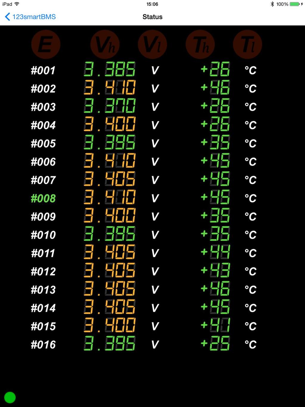
17 The light bulb shows the status of the outgoing energy, next to this graphic presentation you will find details like: consumed current, consumed power, consumed energy today, total of consumed energy. When you Tab the i sign off the battery you will enter the battery details section. Battery details The battery details shows you detailed info of the battery pack. Cell voltage and temperature of each cell will be shown. Please be aware the temperature during bypass mode is much higher than the really cell temperature. Green values are in the safe range, yellow values shows balancing cells and red values are out of the safe range cells (above V max or below V min for example) On top of the screen five warning lights will show critical errors. E Cell board communication error, Vh Exceeding maximum cell voltage, Vl Exceeding minimum cell voltage, Th exceeding maximum cell temperature, Tl exceeding minimum cell temperature.
18
19 Controlling external components On the OUT Module you will find two bi stable signal relays to control external components of your off-grid system. This can be solar chargers, Maximum power point trackers, inverters, etc. An example is the enable pin on many Victron inverters. The maximum current through the signal relays is specified in section Specifications. Charge relay There is one relay to control incoming energy components of the system, like MPPT, solar charger et. This relay is called the CHARGE relay. When charging is allowed the green CHARGE LED next to the CHARGE relay will flash every second. When charging is allowed Pin 1 and 2 of the CHARGE relay contacts (see OUT Board details) are closed (pin 2 & 3 are open). When charging is NOT allowed Pin 2 and 3 of the CHARGE relay contacts are closed (pin 1 & 2 are open). Note: when switching inductive loads like a relay/contactor, make sure there is a protection against flyback of the coil. A simple example is the flyback diode parallel to the coil. Load relay The other relay is to control outgoing energy components of the system, like inverters or other consumers. This relay is called the LOAD relay. When discharging is allowed the green LOAD LED next to the LOAD relay will flash every second. OUT Board v2.x When discharging is allowed pin 2 and 3 of the LOAD relay contacts (see OUT Board details) are closed (pin 1 & 2 are open). When discharging is NOT allowed pin 1 and 2 of the LOAD relay contacts are closed (pin 2 & 3 are open). OUT Board v1.x When discharging is allowed pin 1 and 2 of the LOAD relay contacts (see OUT Board details) are closed (pin 2 & 3 are open). When discharging is NOT allowed pin 2 and 3 of the LOAD relay contacts are closed (pin 1 & 2 are open). Note: when switching inductive loads like a relay/contactor, make sure there is a protection against flyback of the coil. A simple example is the flyback diode parallel to the coil.
20 Switching combined charger/inverter It is possible to use a combined charger/inverter. Just use 1 current sensor and connect this sensor to J1. Make sure to run the current cable the right way through the current sensor. When charging, you should see a positive current in the app next to the battery icon. When discharging, you should see a negative current. Combined charger/inverter with two enable/disable signals, one for charger and one for inverter You can keep the BMS in normal mode and use the charge relay for the enable/disable signal of the charger and the load relay for the enable/disable signal of the inverter. Combined charger/inverter with 1 enable/disable or no enable/disable signal In normal mode the BMS will switch off the charge relay when the battery pack is full. However, this would mean the shared power will be switched off and the user is not able to discharge. For this case the BMS can be configured in critical mode. The BMS will only switch the power off in case there is a critical error condition. Connect the charge and load relay of the BMS in series to get a combined charge/load signal. Now you can switch a power relay or the enable/disable signal of the device. The charger/inverter floating voltages need to match the battery pack to operate correctly.
21 Algorithm SOC calculation The SOC is calculated by constantly measuring the in- and outgoing currents and integrating these currents. This is called Coulomb counting. The SOC is recalibrated every time the pack is full. This is done to reduce SOC calculation deviations. In BMS normal mode, the SOC is set to 100% when all cell voltages are >= V-Bypass. In BMS critical mode, the SOC is set to 100% when the total pack voltage is >= V-Bypass x total number of cells. In other words, when the average cell voltage is >= V-bypass. Charge and discharge/load relay The tables below display the conditions for each relay to switch on or off, depending on the selected mode. Normal mode Charge Discharge/load Enable Disable Enable Disable All cell voltages < V- Cell voltage >= V-max All cell voltages > V- bypass min AND SOC < charge All cell voltages >= V- AND SOC >= discharge Cell voltage <= V-min restart bypass restart AND cell temperature > T-min Cell temperature < T- min AND cell temperature > T-min Cell temperature < T- min AND cell temperature < T-max Cell temperature > T- max AND cell temperature < T-max Cell temperature > T- max AND cell communication No cell communication AND cell communication No cell communication
22 Critical mode Charge Discharge/load Enable Disable Enable Disable All cell voltages < V- Cell voltage >= V-max All cell voltages > V- Cell voltage <= V-min max min AND cell temperature > T-min Cell temperature < T- min AND cell temperature > T-min Cell temperature < T- min AND cell temperature < T-max Cell temperature > T- max AND cell temperature < T-max Cell temperature > T- max AND cell communication No cell communication AND cell communication No cell communication

23 Module details In Board Battery + LED BMS OUT Mount hole for the 'plus'-pole of the cell. Indicator LED, Flashes when active, continuous ON when the bypass mode is active. Interconnection connector for the data link to the next cell board. Option switches See page 7. To minus (-) of the battery Solder a wire on the solder pad and connect this wire to the minus (-) side of the cell. Current sensor charger Current sensor consumers Extended data output Connector for the current sensor of the incoming current (solar). Connector for the current sensor of the outgoing current (consumers). Data output for external modules to receive information about the battery pack.

24 Between Boards Battery + Mount hole for the 'plus'-pole of the cell. To minus (-) of the battery Solder a wire on the solder pad and connect this wire to the minus (-) side of the cell. LED BMS IN BMS OUT Indicator LED, Flashes when data will be received / send, continuous ON when the bypass mode is active. Data input from the previous cell board or IN-Board. Use the inner connector hole marked with the text IN. Data output to the next cell board or OUT-Board. Use the inner connector hole marked with the text OUT.

25 Out Board Battery + Mount hole for the 'plus'-pole of the cell. To minus (-) of the battery Solder a wire on the solder pad and connect this wire to the minus (-) side of the cell. Info LED Load LED Charge LED BMS IN Button Charge relay contacts Load relay contacts Extended data output Indicator LED. Flashes when BMS data is received and load and charge relays are off, continuous ON when the bypass mode is active. Flashes when load relay is active and BMS data is received. Flashes when charge relay is active and BMS data is received. Interconnection connector for the data link to the previous cell board. Button for Bluetooth configuration and password reset. Relay for cutting off chargers, MPPT, solar chargers etc. In case of full batteries. Relay for cutting off consumers like inverters, etc. In case of empty batteries. Data output for external modules.
26 Frequently asked questions No communication No battery data on the app and the E sign will light ON in the battery details tab of the App. Check the flashing LED s on the string of cells. The position where the LED s stop flashing is the location of the problem. Check wiring or replace cell modules. Forgot my password Press and hold the Bluetooth button for 5 seconds, the password will be set the standard Bluetooth does not work Make sure your phone supports Bluetooth 4.0 LE. The following steps can help to connect to the BMS. 1. Restart the App and check in de Settings screen if the BMS appears. 2. Restart your phone and open the App to check again. 3. If you have OUT board version <1.8, press the blue OUT board button and retry. 4. Try a different phone, download the 123SmartBMS app and check if you see the BMS in the device list. 5. Disconnect the OUT Module of the battery cell. Close the App. Press and hold the Bluetooth button while you re-connect the OUT Module on the cell. The OUT module will take approximately 10 seconds to reconfigure the Bluetooth. Now open the app again and check if the device appears in the Settings screen. Only one current sensor or cable It is possible to only use 1 current sensor, the BMS will also work perfectly fine. Using one sensor will use less power on the IN board. The drawback is that you cannot measure incoming and outgoing currents independently, but only see the current going in or out the battery pack. Connect the current sensor to J1 on the IN board and make sure to see a positive current in the App next to the battery icon when charging and a negative current when discharging. Current sensor is not zero in idle mode Make sure there is running absolutely no current through the current sensors during the zero calibration procedure. On the IN module you will find the option switches. Set option switch number 4 to the ON position. Now the set to zero procedure will be active. The currents on the App screen will show 0 Amps in a couple of seconds. Set the option switch number 4 back to the OFF position again. Also set option switch number 3 to ON as the blind spot is recommended.
27 Multiple battery cells or packs parallel There is a difference between placing multiple cells parallel or packs parallel. Multiple cells parallel You can safely place multiple cells parallel and only need 1 BMS cell module per parallel group. For instance: a 12V LiFePO4 pack consists of 4 cell groups in series. In case you have 8 cells, the pack is configured as 2P4S (groups of 2 cells parallel, then these parallel groups in series). In this case you only need 1 BMS for 4S (4 cell groups). Multiple battery packs parallel When you have to connect multiple packs parallel, you need 1 complete BMS per pack. You can connect the signal relays on each OUT board in series. For instance: with 3 packs parallel, you can run the charging signal through from the first OUT board Charge relay to the second Charge relay and through the third Charge relay. This signal can switch an enable/disable or power relay. The same goes for the Load relays in series.
User manual. BMS123 Smart
 User manual BMS123 Smart Introduction After the introduction of affordable LiFePO4 batteries, off-grid solutions became feasible. It is vital that such batteries are charged very carefully. In other words,
User Manual. BMS123 Smart
 User Manual BMS123 Smart Introduction After the introduction of affordable LiFePO4 batteries, off-grid solutions became available for wide public. It is vital that such batteries are charged very carefully.
BMS-LiFePower. 123SmartBMS. Instruction manual
 BMS-LiFePower 123SmartBMS Instruction manual Index Introduction...2 Keep the batteries in perfect condition...2 Package contains (12 Volt, 4 cells)...3 Specs...3 Placing the cell modules...4 Mounting the
User Manual 123electric Battery Management System 123\BMS Revision 1.4 Augusts 2015
 User Manual 123electric Battery Management System 123\BMS Revision 1.4 Augusts 2015 Table of contents Introduction... 3 System structure... 3 Keep the batteries in a perfect condition : ALWAYS!... 5 Specifications...
SimpliPhi Power PHI Battery
 Power. On Your Terms. SimpliPhi Power PHI Battery INTEGRATION GUIDE: VICTRON Optimized Energy Storage & Management for Residential & Commercial Applications Utilizing Efficient, Safe, Non-Toxic, Energy
BMS16 v cell Lithium Battery Management System
 ZERO EMISSION VEHICLES AUSTRALIA http://www.zeva.com.au Safety Warning Although 8-16 cell lithium battery packs do not involve lethal voltages, they frequently involve dangerous amounts of current and
Hub-4 / grid parallel - manual
 Hub-4 / grid parallel - manual Note: make sure to always update all components to the latest software when making a new installation. Introduction Hub-4 is a Grid-parallel Energy Storage system, using
:34 1/15 Hub-4 / grid parallel - manual
 2016-02-24 11:34 1/15 Hub-4 / grid parallel - manual Hub-4 / grid parallel - manual Note: make sure to always update all components to the latest software when making a new installation. Introduction Hub-4
EV Display User Guide
 EV Display User Guide CleanPowerAuto LLC Brief Description: EV Display is designed to track battery state of charge and other related data in battery powered Electric Vehicle. EV Display is primarily designed
INSTALLATION INFORMATION
 INSTALLATION INFORMATION BMS ZE6000i-PCBT.xxxx / ver. 2 Programmable battery management system for Lithium Ion battery cells, for up to 32 round or prismatic cells, 10 to 400Ah NOTE: This installation
PV Master OPERATION MANUAL
 PV Master OPERATION MANUAL GoodWe Technical Services Center December, 2017 Ver. 1.00 BRIEF INTRODUCTION PV Master is an external application for GoodWe inverters to monitor or configure inverters or to
:43 1/13 Victron & BYD B-Box
 2018-11-04 15:43 1/13 Victron & BYD B-Box Victron & BYD B-Box The combination of Victron products with BYD B-Box lithium batteries (2.5, 5.0, 7.5, 10.0 and 12.8 models) has been tested and certified by
MB A 12V/24V DC PROGRAMMABLE DUAL BATTERY ISOLATOR
 MB-3688 120A 12V/24V DC PROGRAMMABLE DUAL BATTERY ISOLATOR User Manual Warning and Precautions MB-3688 is built with corrosion resistant material and the main electronic assembly is well sealed inside
Whizbang Jr. Installation Instructions
 Whizbang Jr. Installation Instructions The Whizbang Junior provides highly accurate current sensing when used with compatible Midnite Solar products. However, for our customers that already own similar
CBC-9130 / V 30A / 24V 15A Pro. Charger. Operation manual
 CBC-9130 / 9215 12V 30A / 24V 15A Pro. Charger Operation manual Keep this manual in a safe place for quick reference at all times. This manual contains important safety and operation instructions for correct
Lester Electrical ChargerConnect App User s Guide
 Lester Electrical ChargerConnect App User s Guide Lester Electrical Summit Series II chargers features Bluetooth wireless communication, which can be accessed using an Apple or Android smart phone, tablet,
SOLAR SMART. 12/24V 20Amp MPPT Solar Charge controller with Ethernet
 SOLAR SMART 12/24V 20Amp MPPT Solar Charge controller with Ethernet Embedded web pages, SNMP support, output port for external Relay board and GSM SMS unit port USER MANUAL PLEASE READ THIS MANUAL CAREFULLY
Manual. EN Appendix. Lynx Ion BMS 400A / 1000A
 Manual EN Appendix Lynx Ion BMS 400A / 1000A 1. SAFETY INSTRUCTIONS 1.1 In general Please read the documentation supplied with this product first, so that you are familiar with the safety signs en directions
Types batteries. AGM Gel OpZs OpZv Lead Carbon LiFePO4 NCA Saltwater Zinc Bromine Etc,etc, etc, etc, etc, etc,
 Batteries Types batteries AGM Gel OpZs OpZv Lead Carbon LiFePO4 NCA Saltwater Zinc Bromine Etc,etc, etc, etc, etc, etc, Today focus on Victron batteries AGM Gel OpZs OpZv Lead Carbon LiFePO4 NCA Saltwater
Elite Power Solutions Automatic Battery Control (ABC) Operation Manual
 Operation Manual") Elite Power Solutions Automatic Battery Control (ABC) Operation Manual Elite Power Solutions 335 E Warner Rd. STE 3 Chandler, AZ 85225 www.elitepowersolutions.com ABC Operation Manual Page 1 Table of Contents
Elite Power Solutions Automatic Battery Control (ABC) Operation Manual Elite Power Solutions 335 E Warner Rd. STE 3 Chandler, AZ 85225 www.elitepowersolutions.com ABC Operation Manual Page 1 Table of Contents
Installation and User Manual. with RAIN SENSOR.
 with RAIN SENSOR www.solarsmartopener.com Revision..0 TABLE OF CONTENTS Features In The Box Further Items Required Basic Operation Solar Panel and Operator Installation Operator Installation Solar Panel
EV Power - A-Series 8 Cell, 16 Cell and 24Cell Chargers Installation & Usage Instructions.
 A-CHARGERS MANUAL 1.1 EV Power - A-Series 8 Cell, 16 Cell and 24Cell Chargers Installation & Usage Instructions. A-Series Charger Features - Simple to install and use, microprocessor control. - LiFePO4
Coleman Air Diversion Controller Model C40
 Coleman Air Diversion Controller Model C40 Version 2.0 With Extended Diversion Mode Designed for 12 volt battery based systems. The Coleman Air model C40 charge controller is a compact, simple to use controller
ECT Display Driver Installation for AP2 Module
 ECT Display Driver Installation for AP2 Module Overview The ECT Display Driver is a small module with a removable wire harness that mounts behind the driver's foot well cover. All wiring connections are
Instruction of Solar Charge Controller. User s Manual
 Instruction of Solar Charge Controller User s Manual 12V/24V 30A Dear Users: Thank you for selecting our product. Please read this manual carefully before you use this product. The controller is for off-grid
EV Power - Battery Control Unit Instructions. 8 Cell 24V
 EV Power - Battery Control Unit Instructions. 8 Cell 24V PAGE 1 OF 12 BCU-EVPPAK Features - Simple to install and use, microprocessor control. - Low power requirement, just 15mA when switched on with relay
BMS SV 24S for 2S-24S LiPo, LiFe & LiTO&others Low power consumption High accuracy 2.8 TFT LCD display Programmable
 BMS SV 24S for 2S-24S LiPo, LiFe & LiTO&others Low power consumption High accuracy 2.8 TFT LCD display Programmable Thanks for your purchasing the for your vehicle. Read the ENTIRE instruction manual to
Installation and operating instructions. Solar charge controller MPPT 10 A / 20 A Z Z
 Installation and operating instructions Solar charge controller MPPT 10 A / 20 A EN 1 Contents 1. About these instructions... 3 1.1 Applicability... 3 1.2 Users... 3 1.3 Description of symbols... 3 2.
KiloVault - HLX Series Lithium Iron Phosphate (LiFePO4) Deep Cycle Solar Batteries. Installation and Users Manual. Rev
 Deep Cycle Solar Batteries. Installation and Users Manual. Rev") KiloVault - HLX Series Lithium Iron Phosphate (LiFePO4) Deep Cycle Solar Batteries Installation and Users Manual 1 The KiloVault HLX series of solar lithium batteries were specifically designed and tested
KiloVault - HLX Series Lithium Iron Phosphate (LiFePO4) Deep Cycle Solar Batteries Installation and Users Manual 1 The KiloVault HLX series of solar lithium batteries were specifically designed and tested
SMT. Installation and Operation Manual. Model:SMT WITH MPPT TECHNOLOGY
 SMT WITH MPPT TECHNOLOGY Installation and Operation Manual Model:SMT SMT Dimensions Specification Summary System Voltage 12 V/24V Rated Battery Current 12V, 5A 8A 10A 15A 20A 25A 24V, 5A 8A 10A 15A Rated
Wired Real Time GPS Installation Instructions
 Wired Real Time GPS Installation Instructions This page intentionally left blank. TABLE OF CONTENTS 1. Introduction 2 2. Selecting the Mounting Location for the Device. 3 3. Mounting the Device 5 4. Optional
βeta 20A AUTO 12V/24V SOLAR CHARGE CONTROLLER WITH REMOTE METER
 βeta 20A AUTO 12V/24V SOLAR CHARGE CONTROLLER WITH REMOTE METER USER MANUAL βeta 20A AUTO 12V/24V SOLAR CHARGE CONTROLLER WITH REMOTE METER (OPTIONAL) CHARACTERISTICS LCD display: all systems parameters
SP PRO ABB Managed AC Coupling
 SP PRO ABB Managed AC Coupling Introduction The SP PRO ABB Managed AC Coupling provides a method of linking the ABB PVI-3.0/3.6/4.2- TL-OUTD and ABB PVI-5000/6000-TL-OUTD string inverters to the SP PRO
PF3100 TROUBLESHOOTING SOLUTIONS TO COMMON PROBLEMS. v1.1 Revised Nov 29, 2016
 PF3100 TROUBLESHOOTING SOLUTIONS TO COMMON PROBLEMS v1.1 Revised Table of Contents 1 Common Alarms and Warnings... 1 2 Common Issues... 6 2.1 Communication problems... 6 2.1.1 Controller communication
User Manual WatchPower App
 User Manual WatchPower App Management Software for Inverter Table of Contents 1. Introduction... 1 2. WatchPower App Install and Uninstall... 1 2.1. System Requirement... 1 2.2. Software Install... 1 2.3.
CPi. CoiL PACK IGNiTioN FOR AViATiON. For 4,6 and 8 cylinder 4 stroke applications. Please read the entire manual before beginning installation.
 1 CPi CoiL PACK IGNiTioN FOR AViATiON Coil pack (4 cylinder) Coil pack (6 cylinder) For 4,6 and 8 cylinder 4 stroke applications. Please read the entire manual before beginning installation. Software version
SK-10. Features. Solar Charge Controller User Manual. Important Safety Information
 SK-10 Solar Charge Controller User Manual 12V/24V 10Amp Dear Users: Thank you for selecting our product. Please read this manual carefully before you use this product. This product is of cutting edge design,
ME-ARC. Remote Control. Owner s Manual (for Revision 2.1 or higher) Inverting
 Inverting") ME-ARC Remote Control Inverting DC 12.6V 50A Owner s Manual (for Revision 2.1 or higher) Disclaimer of Liability Since the use of this manual and the conditions or methods of installation, operation, use
ME-ARC Remote Control Inverting DC 12.6V 50A Owner s Manual (for Revision 2.1 or higher) Disclaimer of Liability Since the use of this manual and the conditions or methods of installation, operation, use
Introduction of EzManage Application
 Introduction of EzManage Application GoodWe Technical Services Center Dec 20, 2016 BRIEF INTRODUCTION EzManage is an external monitoring/ configuration application for GoodWe hybrid inverters, used on
installation manual 123\TUNE+
 installation manual 123\TUNE+ WIRING THE 123\TUNE+ The 123/TUNE+-4-R-V and the 123\TUNE+-6-R-V can be used on cars with battery-minus connected to the body of the car ( NEG-EARTH ), but also on cars with
KiloVault - HLX Series Lithium Iron Phosphate (LiFePO4) Deep Cycle Solar Batteries. Installation and Users Manual. Rev
 Deep Cycle Solar Batteries. Installation and Users Manual. Rev") KiloVault - HLX Series Lithium Iron Phosphate (LiFePO4) Deep Cycle Solar Batteries Installation and Users Manual 1 The KiloVault HLX series of solar lithium batteries were specifically designed and tested
KiloVault - HLX Series Lithium Iron Phosphate (LiFePO4) Deep Cycle Solar Batteries Installation and Users Manual 1 The KiloVault HLX series of solar lithium batteries were specifically designed and tested
User Manual Solar Charge Controller 3KW
 User Manual Solar Charge Controller 3KW Version: 1.3 CONTENTS 1 ABOUT THIS MANUAL... 1 1.1 Purpose... 1 1.2 Scope... 1 1.3 SAFETY INSTRUCTIONS... 1 2 INTRODUCTION... 2 2.1 Features... 2 2.2 Product Overview...
Enerdrive Lithium-Ion Battery System
 Enerdrive Lithium-Ion Battery System After 2 years of research, testing and proving, and a further 2 years of infield sales, Enerdrive has designed and created a COMPLETE Lithium Battery & Installation
SOLN1 25 V2 Quick Start User Guide & Operating Recommendations
 SOLN1 25 V2 Quick Start User Guide & Operating Recommendations For Fully Assembled Units and Fast Build Kits Thank-you for supporting the SOLN1 Project by purchasing a SOLN1 25. This Quick Start User Guide
BMS24. Thanks for your purchasing the BMS24 for your vehicle.
 BMS24 for 2S-24S LiPo & LiFe Low power consumption High accuracy 2.8 TFT LCD display Programmable Thanks for your purchasing the BMS24 for your vehicle. Read the ENTIRE instruction manual to become familiar
SimpliPhi Power PHI Battery
 Power. On Your Terms. SimpliPhi Power PHI Battery INTEGRATION GUIDE: MAGNUM ENERGY Optimized Energy Storage & Management for Residential & Commercial Applications Utilizing Efficient, Safe, Non-Toxic,
Battery Fuel Gauge Specification
 Battery Fuel Gauge Specification Model Number: EJ-FG09 Doc No: SPE-FG-0068 Version: 01 Date: 2014-02-18 Prepared Checked Approved Sara Jess John Manufacturer reserves the right to alter or amend the approval
Low Frequency Inverter. User Manual
 Pure Sine Wave 220-240V 50-60Hz Low Frequency Inverter User Manual For LK/LW series Power Star inverters only, models: LK2000, LK2000-24, LK3000, LK3000-24, LK3000-48, LK6000-24, LK6000-48 1. Safety precautions
User Manual. Solar Charge Controller 3KW
 User Manual Solar Charge Controller 3KW 1 CONTENTS 1 ABOUT THIS MANUAL... 3 1.1 Purpose... 3 1.2 Scope... 3 1.3 SAFETY INSTRUCTIONS... 3 2 INTRODUCTION... 4 2.1 Features... 4 2.2 Product Overview... 5
EV Display V4 User Guide
 EV Display V4 User Guide CleanPowerAuto LLC Brief Description: EV Display a.k.a SOC Gauge is designed to track battery state of charge and other related data in battery powered Electric Vehicle. EV Display
Coleman Air Diversion Controller Model C40
 Coleman Air Diversion Controller Model C40 Designed for 12 volt battery based systems. The Coleman Air model C40 charge controller is a compact, simple to use controller specifically designed for use with
Just connect to the engine and go!
 For Boats all4 solar Australia Just connect to the engine and go! Lithium iron(ferite) batteries (LIFEPO04) only weigh 35-40% of lead acid batteries (depending on the size). Over 90% of the energy capacity
KiloVault - HLX Series Lithium Iron Phosphate (LiFePO4) Deep Cycle Solar Batteries. Installation and Users Manual. Rev
 Deep Cycle Solar Batteries. Installation and Users Manual. Rev") KiloVault - HLX Series Lithium Iron Phosphate (LiFePO4) Deep Cycle Solar Batteries Installation and Users Manual 1 The KiloVault HLX series of solar lithium batteries were specifically designed and tested
KiloVault - HLX Series Lithium Iron Phosphate (LiFePO4) Deep Cycle Solar Batteries Installation and Users Manual 1 The KiloVault HLX series of solar lithium batteries were specifically designed and tested
SmartON / SmartON+ Installation and Use Manual
 SmartON / SmartON+ Installation and Use Manual Rev. Date Ver. Ver. Notes document document SmartON SmartViewII 1.0 06/04/2007 3.08 2.30 Pre-release 1.01 10/04/2007 3.08 2.30 Release 1.02 04/10/2007 3.09
PSIM Tutorial. How to Use Lithium-Ion Battery Model
 PSIM Tutorial How to Use Lithium-Ion Battery Model - 1 - www.powersimtech.com This tutorial describes how to use the lithium-ion battery model. Some of the battery parameters can be obtained from manufacturer
Installing a Programmed Fronius SCERT in a Managed AC Coupled system
 Installing a Programmed Fronius SCERT in INTRODUCTION This document is included with Fronius SCERT PV Inverters that have been programmed. It applies only to units that have been programmed and are ready
P1110-EVAL-PS. PowerSpot RF Wireless Power Development Kit for Battery Recharging. User Manual
 P1110-EVAL-PS PowerSpot RF Wireless Power Development Kit for Battery Recharging User Manual Overview The PowerSpot RF Wireless Power Development Kit for Battery Recharging is a complete demonstration
Installation Guide B-BOX Pro2.5 ~ 10.0
 Installation Guide B-BOX Pro2.5 ~ 10.0 20170625 Version:2.1 1 / 37 Content Safety... 4 1 Product overview... 5 2 Cabinet terminal introduction... 6 3 Cable outlet of cabinet... 7 4 B-Plus2.5 interface
Universal Wireless Dashboard Y-Dash + Android App Y-Dash GT. User Manual Firmware version 1.6 Software version 2.28 Hardware version 1.
 Universal Wireless Dashboard + Android App GT User Manual Firmware version 1.6 Software version 2.28 Hardware version 1.3 Page 2 is an electronic microprocessor based device that collects analog and digital
Manual. Lynx Ion 24V/180Ah Lithium Ion Batteries
 Manual EN Lynx Ion 24V/180Ah Lithium Ion Batteries Copyrights 2012 Victron Energy B.V. All Rights Reserved This publication or parts thereof, may not be reproduced in any form, by any method, for any
Orion 2 BMS Operation Manual
 www.orionbms.com Orion 2 BMS Operation Manual The Orion BMS 2 by Ewert Energy Systems is the second generation of the Orion BMS. The Orion BMS 2 is designed to manage and protect Lithium ion battery packs
OPTI-Solar SC MPPT Series
 www.opt i -sola r. c o m OPTI-Solar SC MPPT Series SOLAR CHARGE CONTROLLER SC-50 / SC-80 / SC-80X / SC-160X MPPT Installation and Operation Manual CONTENTS Introduction... Feature... Specification... Dimension...VII
User Manual 1KVA-5KVA INVERTER / CHARGER
 User Manual 1KVA-5KVA INVERTER / CHARGER Version: 1.7 Table Of Contents ABOUT THIS MANUAL... 1 Purpose... 1 Scope... 1 SAFETY INSTRUCTIONS... 1 INTRODUCTION... 2 Features... 2 Basic System Architecture...
4 Electric Circuits. TAKE A LOOK 2. Identify Below each switch, label the circuit as a closed circuit or an open circuit.
 CHAPTER 17 4 Electric Circuits SECTION Introduction to Electricity BEFORE YOU READ After you read this section, you should be able to answer these questions: What are the three main parts of a circuit?
VC-4820 Programmable DC-DC Converter with Battery Charger function USER'S MANUAL
 1. INTRODUCTION VC-4820 Programmable DC-DC Converter with Battery Charger function USER'S MANUAL This MCU controlled Step Down DC-DC Converter has a digitally adjustable output in 0.2V increments. This
27/10/2015 GENERAL. A. Yes. Z21 is a single phase unit, it will however operate correctly on any phase.
 Z21 SERIES HYBRID Q: Can this be used as an Off-Grid inverter? GENERAL A: A Z21 is not designed to work solely as an off-grid inverter. The off-grid function is delivered via emergency backup output when
CRAGG RAILCHARGER Instruction Manual for 20SMC-12V 20SMC-24V 40SMC-12V 40SMC-24V 60SMC-12V 80SMC-12V
 CRAGG RAILCHARGER for 20SMC-12V 20SMC-24V 40SMC-12V 40SMC-24V 60SMC-12V 80SMC-12V Contents 1 Warnings, Cautions, and Notes... 1 2 Description... 2 3 Features... 2 3.1 STANDARD FEATURES... 2 3.2 OPTIONAL
Rover Series. Rover 20A 40A Maximum Power Point Tracking Solar Charge Controller
 Rover Series Rover 20A 40A Maximum Power Point Tracking Solar Charge Controller 0 2775 E. Philadelphia St., Ontario, CA 91761 1-800-330-8678 Version 1.5 Important Safety Instructions Please save these
100W Basic Kit (GS-100-Basic)
") 100W Basic Kit (GS-100-Basic) Kit Sizing Guide Copyright 2015, Grape Solar, Inc. All Rights Reserved Valid from July 2015 www.grapesolar.com Valid from July 2015 1 Step By Step Setup Basic Wiring Diagram
100W Basic Kit (GS-100-Basic) Kit Sizing Guide Copyright 2015, Grape Solar, Inc. All Rights Reserved Valid from July 2015 www.grapesolar.com Valid from July 2015 1 Step By Step Setup Basic Wiring Diagram
Enginer Brand Po Box 185 Birmingham, Michigan
 Enginer Brand Po Box 185 Birmingham, Michigan 48009 Sales www.enginer.us 877.886.8897 +1 248.747.4700 Toyota Brand Vehicles Prius / Camry /Lexus CT 200 PHEV Conversion 4 Kwh and
APPLICATION NOTE: CLOSED LOOP INTEGRATION WITH XANBUS ENABLED SCHNEIDER ELECTRIC CONEXT PRODUCTS
 APPLICATION NOTE: CLOSED LOOP INTEGRATION WITH XANBUS ENABLED SCHNEIDER ELECTRIC CONEXT PRODUCTS 1. Safety 3 1.1 Warnings, Cautions and Notes 3 1.2 General Warning 1.3 Fire Risk 3 1.4 Electric Shock Risk
TECHNICAL NOTE #4 Revised May 24, BOGART ENGINEERING Two Bar Road, Boulder Creek, CA (831)
") TECHNICAL NOTE #4 Revised May 24, 2004 BOGART ENGINEERING 19020 Two Bar Road, Boulder Creek, CA 95006 (831) 338-0616 TROUBLESHOOTING the TriMetric battery monitor Revised for the TM-2020 TriMetric What
TECHNICAL NOTE #4 Revised May 24, 2004 BOGART ENGINEERING 19020 Two Bar Road, Boulder Creek, CA 95006 (831) 338-0616 TROUBLESHOOTING the TriMetric battery monitor Revised for the TM-2020 TriMetric What
Switch Machines Installation & Wiring
 Switch Machines Installation & Wiring Conventional Twin Coil Switch Machines Electrically: In use since developed by Walthers in early 1930 s Long time standard for remote operation Currently: Rix, Atlas,
Gate & Door Controller with LCD and Intelligent Technology
 2nd Edition Gate & Door Controller with LCD and Intelligent Technology 24Sv1 and 12Sv1 Motor Controllers Setup and Technical information for single motor controller for gates & doors Includes latest Intelligent
Covers All 430, 440, 441 and CJ Series Advanced Security Systems.
 INSTALL GUIDE Covers All 430, 440, 441 and CJ Series Advanced Security Systems www.ultrastarters.com Technical Support: 866-698-5872 ext 0 support@ultrastarters.com FCC/ID Notice This device complies with
MPPT75HV MAXIMUM POWER POINT TRACKING SOLAR BATTERY CHARGE CONTROLLER
 MPPT75HV MAXIMUM POWER POINT TRACKING SOLAR BATTERY CHARGE CONTROLLER The Intronics Power Inc. MPPT75HV Solar Charge Controller continually tracks the maximum power point of the solar panel array, adjusting
Super Brain 977. AC/DC Charger with Dual Output and Discharge Function. User s Manual. Model Rectifier Corporation
 Super Brain 977 AC/DC Charger with Dual Output and Discharge Function User s Manual Model Rectifier Corporation 80 Newfield Avenue Edison, NJ 08837-3817 Phone: 732-225-6360 www.modelrectifier.com Please
Manual Installation & Operation
 Manual Installation & Operation Model: NCxxLxx 12A or 30A Solid State Solar Charging Regulator and 12A Load Controller. 231 Patent #: 5,642,030 Applies Page 1 Warnings When Installing, connect grounds,
Idle Timer Controller - ITC515-A Ford Transit Contact InterMotive for additional vehicle applications
 An ISO 9001:2008 Registered Company Idle Timer Controller - ITC515-A 2015-2018 Ford Transit Contact InterMotive for additional vehicle applications Overview The ITC515-A system will shut off gas or diesel
GS-100D+ Preconfigured Kits Manual
 100W 400W GS-100D+ Preconfigured Kits Manual Copyright 2012, Grape Solar, Inc. All Rights Reserved 1 2 Overview The GS-100D+Preconfigured Kits are designed to be modular and expandable solar generators,
1. General Description
 Manual BlueSolar charge controllers MPPT 150/45-Tr MPPT 150/45-MC4 MPPT 150/60-Tr MPPT 150/60-MC4 MPPT 150/70-Tr MPPT 150/70-MC4 MPPT 150/85-Tr MPPT 150/85-MC4 MPPT 150/100-Tr MPPT 150/100-MC4 1. General
User Manual 1.5KVA-3KVA INVERTER / CHARGER. Version: 1.1
 User Manual 1.5KVA-3KVA INVERTER / CHARGER Version: 1.1 Table Of Contents ABOUT THIS MANUAL... 1 Purpose... 1 Scope... 1 SAFETY INSTRUCTIONS... 1 INTRODUCTION... 2 Features... 2 Basic System Architecture...
Instruction of Solar Charge Controller. User s Manual
 Instruction of Solar Charge Controller User s Manual 12V/24V 10A/20A Dear Users: Thank you for selecting our product. Please read this manual carefully before you use this product. 0 The controller is
GS-100+ Preconfigured Kits
 Kit Sizing Guide REV 170615 100 W 200 W 300 W 400 W GS-100+ Preconfigured Kits Kit Sizing Guide Copyright 2012, Grape Solar, Inc. All Rights Reserved www.grapesolar.com Valid from March 2014 1 Kit Sizing
PowerSTAR PS-2024-D. Maximum Power Point Tracking Solar Regulator. w w w. r o c s o l i d. c o m. a u. Contents
 w w w. r o c s o l i d. c o m. a u PowerSTAR PS-2024-D Maximum Power Point Tracking Solar Regulator Contents 1 Quick Start Guide... 2 2 Specifications... 3 2.1 General Operation... 3 2.2 Absolute Maximum
Idle Timer Controller - A-ITC520-A Ford E Series Ford F250 - F Ford F250 - F550 (*B-ITC520-A) F650/F750
 F650/F750") An ISO 9001:2008 Registered Company Idle Timer Controller - A-ITC520-A 2009-2018 Ford E Series 2008-2016 Ford F250 - F550 2017-2018 Ford F250 - F550 (*B-ITC520-A) 2016-2018 F650/F750 *Uses the Ford 24-Pin
An ISO 9001:2008 Registered Company Idle Timer Controller - A-ITC520-A 2009-2018 Ford E Series 2008-2016 Ford F250 - F550 2017-2018 Ford F250 - F550 (*B-ITC520-A) 2016-2018 F650/F750 *Uses the Ford 24-Pin
User manual. Solar Hybrid 1-5KVA. Uninterruptible Power Supply / Charger
 User manual Solar Hybrid 1-5KVA Uninterruptible Power Supply / Charger All rights reserved. The information in this document is subject to change without notice. Thank you for purchasing this series UPS.
Z21 SERIES HYBRID GENERAL BATTERIES. Q: Can this be used as an Off-Grid inverter?
 Z21 SERIES HYBRID Q: Can this be used as an Off-Grid inverter? A: A Z21 is not designed to work solely as an off-grid inverter. The off-grid function is delivered via emergency backup output when the grid
USERS MANUAL / GEBRUIKERSHANDLEIDING / BETRIEBSANLEITING MANUEL D UTILISATION / MANUAL DE UTILIZACION. Masterlink BTM III
 USERS MANUAL / GEBRUIKERSHANDLEIDING / BETRIEBSANLEITING MANUEL D UTILISATION / MANUAL DE UTILIZACION Masterlink BTM III Monitor for three independent battery sets 25.54V - 29.3A 42% 25:14 ENGLISH: PAGE
BMS16. Thanks for your purchasing the BMS16 for your vehicle.
 BMS16 BMS for 2S-16S LiPo & LiFe Low power consumption High accuracy 2.8 TFT LCD display Programmable Thanks for your purchasing the BMS16 for your vehicle. Read the ENTIRE instruction manual to become
HousePower BMS. CleanPowerAuto LLC
 HousePower BMS CleanPowerAuto LLC Features: Designed for 12V and 24V LiFePo4 battery banks, replacing Lead Acid house banks in marine and RV applications, with minimal changes to existing systems and wiring
BMS16T BMS24T. Thanks for your purchasing the BMS16T or BMS24T for your vehicle.
 BMS16T BMS24T for 2S-16S or 2S-24S LiPo, LiFe & LiTO Low power consumption High accuracy 2.8 TFT LCD display Programmable Thanks for your purchasing the BMS16T or BMS24T for your vehicle. Read the ENTIRE
Installation Guide Kratos (B10L)
") Installation Guide Kratos (B10L) Rev 1.1_Mar.2017 1/ 37 Content Safety... 3 1 Product Overview... 4 2 Cabinet terminal introduction... 5 3 Cable outlet of cabinet... 6 4 B10L2.5M interface and terminal
Installation Guide Kratos (B10L) Rev 1.1_Mar.2017 1/ 37 Content Safety... 3 1 Product Overview... 4 2 Cabinet terminal introduction... 5 3 Cable outlet of cabinet... 6 4 B10L2.5M interface and terminal
VECTRIX VX-2 SERVICE MANUAL. Version 1.0/May 2011 VECTRIX, LLC
 www.vectrix.com CONTENTS SECTION A: Tools 1 Tools Needed SECTION B: Mechanical Parts 1 Front Fairing 2 Front Console Cover 3 Speedometer Cover 4 Front Vertical Panel Cover-Lower 5 Front Vertical Panel
User Manual 1KVA/ 2KVA/ 3KVA INVERTER / CHARGER
 User Manual 1KVA/ 2KVA/ 3KVA INVERTER / CHARGER CONTENTS ABOUT THIS MANUAL... 1 Purpose... 1 Scope... 1 SAFETY INSTRUCTIONS... 1 INTRODUCTION... 2 Features... 2 Basic System Architecture... 2 Product Overview...
BlueSolar charge controller MPPT 100/30
 Manual EN Handleiding NL Manuel FR Anleitung DE Manual ES Användarhandbok SE Appendix BlueSolar charge controller MPPT 100/30 1. General Description 1.1 Charge current up to 30 A and PV voltage up to 100
Lithium Power Pack LITHIUM-ION BATTERY SYSTEM. With epro Plus Battery Monitor
 Lithium Power Pack LITHIUM-ION BATTERY SYSTEM With epro Plus Battery Monitor LITHIUM-ION BATTERY SYSTEM After 2 years of research, testing and proving, and a further 5 years of infield sales, Enerdrive
HGM1780. Automatic Genset Controller USER MANUAL. Smartgen Technology
 HGM1780 Automatic Genset Controller USER MANUAL Smartgen Technology Smartgen Technology Co., Ltd No. 28 Jinsuo Road Zhengzhou Henan Province P. R. China Tel: 0086-371-67988888/67981888 0086-371-67991553/67992951
MPPT Controller PVTS Series User Manual. User Manual. 800W-4000W Hybrid solar inverter. Version: 1.4
 User Manual 800W-4000W Hybrid solar inverter Version: 1.4 Table Of Contents ABOUT THIS MANUAL... 1 Purpose... 1 Scope... 1 SAFETY INSTRUCTIONS... 1 INTRODUCTION... 2 Features... 2 Basic System Architecture...
AS-4000 OPERATING INSTRUCTIONS (PS-5000)
") AS-4000 OPERATING INSTRUCTIONS (PS-5000) BASIC OPERATIONS This unit is a state-of-the-art combination of a vehicle alarm and remote starter system. Start by familiarizing yourself with the alarm functions
AS-4000 OPERATING INSTRUCTIONS (PS-5000) BASIC OPERATIONS This unit is a state-of-the-art combination of a vehicle alarm and remote starter system. Start by familiarizing yourself with the alarm functions