RGB Alarm Clock. -Color Alarm Clock-
|
|
|
- Bathsheba Nicholson
- 5 years ago
- Views:
Transcription


1 RGB Alarm Clock -Color Alarm Clock-
2 Table of Contents Preamble:...2 List of parts...3 Components...5 Parts and belongings...5 Clock Board Assembly...8 Identification of SMD parts:...0 The power supply check...23 RTC Module...30 The final assembly...32 Alarm Clock Description...34 Clock Menu...35 Menu settings...36 Menu description...36 Alarm Settings and Display...37
3 Preamble: It's the half battle when you have basic knowledge of electronic, don't be afraid if you are a novice, follow the solder instructions and you will succeed in the end. When you get stuck, don't continue! Take a break and ask a friend who has experience. We take no responsibility for any injury or damage as a result of assembling this kit. The following tools are required to assemble this kit: soldering iron, solder, diagonal cutting pliers, multimeter and a solder sucker is optional. This tools are not included in the delivery content. When you have finished the soldering work then it's necessary to clean up the printed circuit boards with a solution of dish detergent and methylated spirit to avoid current leakage. For a more thorough cleaning you can use a toothbrush. After cleaning them, you have to dry the printed circuit boards. A hairdryer will help you to do the job. It's important that the boards are absolutely dry, that means bone-dry. A wet board can cause a short circuit or current leakage and can damage your clock, or your clock won't work properly. Remember, we take no responsibility for this mistake on your part. Use a suitable power supply unit. (input voltage 9-2 volt and max. ampere). Inappropriate voltage or polarity can cause permanent damage. Don't put any items into the clock. Protect your clock against water and any liquids. Avoid damp rooms when you operate this device. We are delighted that you have chosen this kit.
4 List of parts Pos. Typ SMD 2 SMD 3 SMD 4 SMD 5 THT 6 THT 7 THT 8 THT 9 THT 0 SMD THT 2 THT 3 THT 4 THT 5 THT 6 THT 7 THT 8 THT 9 THT 20 THT 22 THT 23 THT 24 THT 25 THT 26 THT 27 THT 28 THT 29 THT 30 THT 3 THT 32 THT 33 PCB 34 Power 35 Case 36 End Sleeve 37 Bolt 38 Female Screw Optional PCB 2 SMD 3 THT 4 THT 5 THT THT REF R R R R C C C C C U (IC) U (IC) U (IC) U (IC) U (IC) U (IC) J J J J J J F D Q X S SPK CON LDR LD LD Power U (IC) X J J Value Resistor 430 OHM Resistor K OHM Resistor 4.7K OHM Resistor 0K OHM Capacitor 000pF Capacitor 22pF Capacitor 00nF Capacitor 0uF (Tantal) Capacitor 22uF (ELKO) Regulator L494 BDT-TR ATMEGA328-P Schift Registers 74HC595 Schift Registers TPIC6B595 DAC MPC490 DAC MPC4902 IC Socket Dil 8 IC Socket Dil 4 IC Socket Dil 6 IC Socket Dil 20 IC Socket Dil 28 Pin Head Female POLx5 Fuse DIODE N400 MOSFET 2N700 Crystal 6MHZ Switch (TACTILE) BUZZER BARREL JACK LDR RGB LED LED MATRIX Clockboard Power Supply Clock Case 4 Pieces End Sleeve Bolts Female Screws RTC PCB Battery holder RTC Microcontroller Clock Crystal Pin Strip POL x4 Pin Strip POL x Quantity I.O


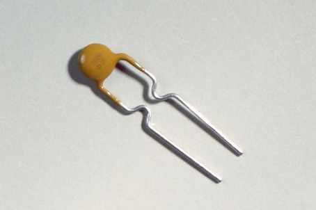
5 Components Printed Circuit Board Clock Enclosure Parts and belongings Pin Head Female Optional: Pin Strip IC Socket Elko Capacitor Ceramic Capacitor Tantal Capacitor


6 SMD Resistor Optional: Clock Crystal Crystal Speaker MOSFET Light Detected Diode Fuse SMD Regulator Microcontroller LED Matrix RGB LED Diode Switch Barrel Jack Power Supply


7 End Sleeves Bolts Optional: Battery Holder Optional: RTC Module Female Screw
8 Clock Board Assembly. First of all we will solder the SMD resistors onto the Printed Circuit Board. In the picture you see the color marked locations. The color must match with the value of the resistors, look on the table below. You can also use the location numbers to allocate the right place for the resistors. Location Color Inscription SMD blue 43 red 02 or 00 yellow 472 green 03 or 002 Value 430 OHM k OHM 4.7k OHM 0k OHM Part Location Nr. R,R2,R3 R6 to R20 R23,R24 R4,R5,R2,R22,R37
9 Naturally, the inscription of the SMD resistors point upward. 2. Turn the PCB onto the other side and place the resistors. We use only 0 k resistors on this side. The resistors R28 till R4 helps to avoid ghosting that caused by the RGB LED's. Location Color Inscription SMD green 03 or 002 Value 0k OHM Part Location Nr. R25 to 36, 37 to R4
10 Identification of SMD parts: The Three Digit System This system is used for less accurate resistors ( tolerance > 5%). The two digits indicate the numerical resistance value of the resistor and the last digit gives a multiplier. The number of the last digit indicates the power of ten by which to multiply the given resistor value. Example : 0 = 0 0 = 0 0 = 00 Ω = 00 Ω 2 Example 2: 02 = 0 0 = 0 00 = 000 Ω = kω Example 3: 03 = 0 03 = = 0000 Ω = 0 kω Example 4: 04 = 0 04 = = Ω = 00 kω The letter R is used to indicate the position of a decimal point for resistance values lower than 0 ohms. Example for the three digit system: R0 would be Ω and 0R0 would be 0.0Ω. The Four Digit System This system is used for more accurate resistors ( tolerance < 5%). The three digits indicate the numerical resistance value of the resistor and the last digit gives a multiplier. The number of the last digit indicates the power of ten by which to multiply the given resistor value. Here are some examples of values under this system: Example : 00 = 00 0 = 00 0 = 000 = kω Example 2: 002 = = = 0000 = 0 kω Example 3: 003 = = = = 00 kω The letter R is used to indicate the position of a decimal point for resistance values lower than 00 ohms. Example for the four digit system: 0R0 would be 0 Ω. Read more
11 3. Place and solder the IC Sockets. The notches on the sockets must match with the notch in the silkscreen. The table below helps you to place the sockets on the right location. Pole Sockets For The Micro Controller MPC490 MPC4902 Schiftregister 47HC595 Schiftregister TPIC6B595 Atmega 328P Part Location Nr. U4 U3 U5,U6 U7,U8 U

12 4. It is very important that you place the diodes in the right direction. If you have placed the diode D2 wrong, no current will flow and the clock won't work. The worse case happens when you place the Diode D in the wrong direction, most IC's will take damages and they could heat up, and be sure your clock will never work again. The diodes have a silver strip at the end. Make sure this strip matches the strip in the silkscreen image. Look for the right location, bent the leads and now place and solder the diodes D and D2. The ring on the diode marks the current direction.

13 5. Lay the SMD regulator U2 on the marked place on the backside of the printed circuit board. Align the component and solder them. Make sure that no solder joins the pins. The regulator reduce the power form 9 Volt to 5 Volt.

14 6. Tack and solder the crystal X. The crystal has a frequency at Hertz pro second and beats the clock.

15 7. A capacitor is a passive two terminal electrical component that stores electrical energy in an electric field. In this circuit we use the capacitors to smooth the power supply output and reduce electric noise.. Now it is time to solder the ceramic capacitors. A look on the picture will help you to place the capacitors onto the right spot. Location Color green blue red Inscription Value 000 pf 22 nf 00 nf Part Location Nr. C6 C3,C4 C,C5,C7,C9
16 Electrolytic and tantal capacitors are two poles components. Look at the longer wire, that is the positive pole. It is very important to double check that the positive pole match with the + on the silkscreen. You may have noticed a broad strip on the electrolytic capacitor which is marked. This side is the negative pole. Be aware of a wrongly connected capacitor won't work at all. In the worst case the capacitor could explode! Now place the electrolytic capacitor onto the location C. The location C8 and C0 are reserved for the tantal capacitor. Typ Inscription Part Location Nr. Elko 22 uf C2 Tantal 0 uf C8,C0

17 8. Solder the fuse. The fuse protect the electric circuit against excessive current. The fuse will heat up and cut off the power supply. After a while the fuse cools down, it resets and the current flows again. Now look for the right location F, place and solder the fuse onto your board. Ensure that the fuse not touch the enclosure after you have solder them. Draw the fuse tight to the printed circuit board.


18 9. Your alarm clock needs a speaker to wake you up in the morning! Make sure the positive pole matches the silkscreen. Have you placed the speaker the wrong sides then no sound will come out. Now solder the speaker. The longer wire is the positive pole.


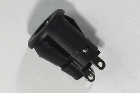
19 0. Tack the power jack CON on the backside of your Clock Board. It is very important that you place the power jack with the right polarity onto your board. Double check and solder the component onto the topside. It takes some time to heat up the metal and make sure there is plenty of solder on the pads. Attention: tack the power jack onto the backside of your pcb and solder the leads on the frontside. Double check polarity and ensure yourself. backside power jack correct mounted power jack

 onto the PCB.")

20 . Place and solder the 5 pol female pin head ISP onto the backside of the circuit board. Via the interface ISP you can reprogram the clock firmware. 2. Solder the Light Detecting Resistor (LDR) onto the PCB. You can mount the LDR on the front- or backside. It is recommended to mount the LDR on the frontside of the board, the sensor reacts faster by light chance. Frontside mounted Backside mounted

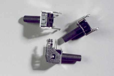
21 3. Before you solder the buttons you should clean the board thoroughly with a solution of dish detergent and methylated spirit. The buttons don't like moisture also the speaker! Important: Make sure that the board is absolutely bone dry after cleaning. Now place and solder the button S,S2,S3
22 4. MOSFET are easily damaged by static discharge. Use an anti-static surface to handle the component. Ensure that you are free of electrostatic charge. Before you handle the component ground yourself, the best way is to touch a radiator or a water pipe to discharged yourself. The half round transistor case must match the half round silkscreen, check twice. Now solder the MOSFET's 2N7000 onto the location Q,Q2 and Q3.
23 The power supply check 5. The power supply check. Look for metal bits they could cause a short circuit before you energize your board. Compare the values with the measure points on the picture. Take time for your measurements and check twice. The voltage can differ at a minimal range, depending on your multimeter tolerance value.

24 Turn the PCB on the other side and measure the violet marked point of the SMD Regulator. The multimeter should you show approximate 8.4 Volt. Shows your multimeter 0 Volt, than you have mounted the Diode D2 in the wrong direction. Maybe you asking your self why 8.4Volt and not 9Volt. The voltage drop is caused between the violet (backside) and the green measure point (frontside) by the protector diode D2. Important: If the power supply check failed, check step by step every instruction point to find the bug. Don't continue until you have find the malfunction and remember we don't take responsibility for any injury or damage as a result of assembling this kit. The wrong voltage and polarity could destroy and overheat the ICs. Disconnect the power supply from the clock board. Was the test successful then you can continue with the next step.
 and energize your clock board.")
25 6. Solder the Matrix LED's The lettering on the LED matrix blog must point at the cat symbol on the silkscreen. Look twice, a incorrectly mounted LED block can not work properly. Advice: solder at first only the corners leads with a few tin solder onto the PCB. Stick on the microchips (see next step) and energize your clock board. Single shining dots should lite up on your Matrix Display.

26 7. Plug on the IC's Take attention to the U-shaped notches they must compare with the silkscreen. Attention: Incorrectly installed micro controllers could heat up, or they will be immediately destroyed. Occasionally it is necessary to bend the pins of the chip, they slide and fit better in the socket. Take a look at the picture, lay the pins parallel onto a flat surface and push them carefully in the right position (pins 90 to the case).

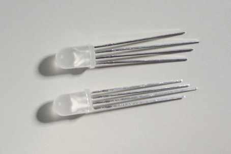
27 8. Assembly the RGB LED's Look at the RGB LED leads, the third blue one marked is the longest, take a look on the close up view picture to ensure yourself. The color marked leads must compare with colored spots on the PCB. Check twice!


28 Close up view: RGB LED Put the bolts through the watch face and pull the end sleeves over them. Mount the PCB with the RGB LED's on the watch face and screw they tight.


29 The crimp of the end sleeve looks upward. Have you aligned all RGB LED correct? Lets make a test. Energize your board and look close at them. You see the the red second hand (LED) moves clockwise around. Align the RGB LED's, push them forward until up to the stop of the dial clock. Now solder the wires tight on.
 Optional you could put on the RTC")


30 RTC Module 9. RTC Module Assembly (Optional) Optional you could put on the RTC Module onto the interface IC2 RTC Module RTC Module Mounted Place the battery holder, the positive pole must match with the silkscreen. As usual the notch of the IC must match. At the end, tack on the crystal. After you have soldered the components you must cut the leads short as possible to avoid short circuit.

31 Tack the 4 pol pin strip onto the location I2C on the back of the PCB. Don't forget to mount the two single pin strips. Now solder them. The same principle is valid also here, cut the leads between the marked area as short as possible to avoid short circuit on the clock board. Pull the RTC Module over the pin strips and solder them tight.

.")
32 The final assembly 20. Final assembly Put the bolts through the dial clock. Mount the four end sleeves, the crimp should look upward. Don t forget do remove the masking film! Again place the last four end sleeves onto the bolts. The crimps pointing down. Assemble the PCB onto the dial without you damage the crystal (violet marked). Place and screw tight the back cover. The crystal must fit in the enclosure hole.

33 At last we put on the supporting foot. Completed clock, the round shaped supporting foot points forward. Every item has a masking film on it to protect the enclosure from minor scratches. Therefore don t forget to remove the masking film!

34 Alarm Clock Description
35 Clock Menu MENU SETTING POINT SETTING POINT 2 SETTING POINT 3
36 Menu settings Step : Press the MENU button to select the menu setting, press again and you will advance to the next menu item. Step 2: Press the SET button to enter the setting mode. You can now change the settings with the ADD button. Step 3: Press the SET button again, you advance to the next settings item. Change the settings with the ADD button. Step 4: When you have reached the last settings item, press the SET button to leave the settings menu and the clock goes into normal operation mode. Menu description Alarm: Time: Date: Screen: Ring: Bright: Glow: Sensor: Beep: Info: You can choose nine different alarms. Time setting. Date setting. Choose your favorite screen mod for displaying on the LED Matrix. The output of the time on the LED Ring can be set to different formats. Adjust the brightness level of the LED Matrix and RGB Ring display. Is this function enabled, the display bright will be set instantly on the maximum level at one hour prior of the time the alarm trigger off and every five minutes a red light dot will be set. When the alarm starts the LED Ring will be instantly and furious blink. Enable the dim function for the automatic display light adjustment. The display bright adapts to the ambient light. Enable the wake function and you can turn on the light to stop the alarm sound (easy wake). When you turn off the light within 0 seconds after the alarm starts the clock will fell in the snooze mod. The snooze mod is only available when you turn on the wake function. Enable the beep function and the clock will beep on every button press. Information about the driver version and designer.

37 Alarm Settings and Display Press the Add button to enable or disable the Alarm. To switch the alarm time press the Set button.


38
ELECTRIC FENCE ENERGIZER SERVICE MANUAL MODEL 950 SERVICE MANUAL FOR OLLI 950 FENCE ENERGIZERS
 ELECTRIC FENCE ENERGIZER MODEL 950 SERVICE MANUAL Service Manual for OLLI 950 Page 1/16 Date 20.10.2014 Table of Contents...1 1. IMPORTANT SAFETY INSTRUCTIONS...2 2. SPECIFICATIONS...3 3. CONSTRUCTION...4
C capacitance, 91 capacitors, codes for, 283 coupling, polarized and nonpolarized,
 Index Numbers and Symbols 555 timer, 164 166 making sound using, setting output speed of, 166 167 using for reaction game speed, 260 261 μf (microfarad), 92 Ω (ohms), 7, 70 A A (amperes), 7 AC (alternating
Electronic Dice Kit MitchElectronics 2019
 Electronic Dice Kit MitchElectronics 2019 www.mitchelectronics.co.uk CONTENTS Schematic 3 How It Works 4 Materials 5 Construction 6 Important Information 7 Page 2 SCHEMATIC Page 3 SCHEMATIC EXPLANATION
IV-11 VFD tube clock Assembly instructions v1.2.2
 IV-11 VFD tube clock Assembly instructions v1.2.2 Designer: Website: E-mail: Yan Zeyuan. China http://www.nixieclock.org yanzeyuan@qq.com 2017-01-26 NCH Attention Attention: Warning: Warning: Warning:
CHRISTMAS TREE KIT MODEL K-14. Assembly and Instruction Manual ELENCO
 CHRISTMAS TREE KIT MODEL K-14 Assembly and Instruction Manual ELENCO Copyright 2015, 1989 by Elenco Electronics, Inc. All rights reserved. Revised 2015 REV-J 753214 No part of this book shall be reproduced
SUPER CAPACITOR CHARGE CONTROLLER KIT
 TEACHING RESOURCES ABOUT THE CIRCUIT COMPONENT FACTSHEETS HOW TO SOLDER GUIDE POWER YOUR PROJECT WITH THIS SUPER CAPACITOR CHARGE CONTROLLER KIT Version 2.0 Teaching Resources Index of Sheets TEACHING
Quiz Buzzer. Build Instructions. Issue 1.2
 Build Instructions Issue 1.2 Build Instructions Before you put any components in the board or pick up the soldering iron, just take a look at the Printed Circuit Board (PCB). The components go in the side
IV-3 VFD Shield for Arduino. Assembly Manual
 June 2014 Table of Contents 1 Overview Features Applications 3 3 3 2 Assembly Hints 4 3 PCB Overview 5 4 Circuit Diagram 6 5 Assembly Diodes and IC socket Electrolytic capacitors Ceramic capacitors 10K
Schematic VCC J1 1 CON1 +5V D26 D25 D7 D8 D9 D10 D11 D12 D19 D20 D21 D22 D23 D24 D1 D2 D3 D4 D5 D6 D13 D14 D15 D16 D17 D18 R4 100R R2 100R R6 100R
 Schematic +5V S D1 D2 D3 D4 D5 D6 D7 D8 D9 D10 D11 D12 D19 D20 D21 D22 D23 D24 D13 D14 D15 D16 D17 D18 D25 D26 R1 4K7 R2 100R Q1 9014-PNP C1 47uF R3 4K7 R4 100R Q2 9014-PNP C2 47uF R5 4K7 R6 100R Q3 9014-PNP
CTB-16K Hobbyist Line Kit 40 Amp 16 Channel Light Controller Assembly Manual *** Preliminary ***
 CTB-16K Hobbyist Line Kit 40 Amp 16 Channel Light Controller Assembly Manual *** Preliminary *** Version 1.0 January 12, 2006 Copyright Light O Rama, Inc. 2006 Table of Contents 1 Introduction... 3 2 Required
TIMER PROJECT KIT ESSENTIAL INFORMATION. Version 2.0 TIME SOMETHING WITH THIS
 ESSENTIAL INFORMATION BUILD INSTRUCTIONS CHECKING YOUR PCB & FAULT-FINDING MECHANICAL DETAILS HOW THE KIT WORKS TIME SOMETHING WITH THIS TIMER PROJECT KIT Version 2.0 Build Instructions Before you start,
ALARM KIT ESSENTIAL INFORMATION. Version 2.0 WHAT CAN YOU PROTECT WITH THIS
 ESSENTIAL INFORMATION BUILD INSTRUCTIONS CHECKING YOUR PCB & FAULT-FINDING MECHANICAL DETAILS HOW THE KIT WORKS WHAT CAN YOU PROTECT WITH THIS ALARM KIT Version 2.0 Build Instructions Before you start,
D6, D7, D8, D9, D12, D13, D14, D15, D16, D17, D18, D19. Schottky rectifier diode. 1N5817-1N5819 or SB130
 Roll Your Own ljunggrenaudio.com Altered States version 1.0 Bills Of Material Qty Value 12 1N4148 2 1N5818 4 1N750 4.7V 4 220p Device Diode Diode Zener diode Capacitor 30 100n 4 15p 8 560p 1 5x2 pin Capacitor
SCA-80(Q) C11 REPLACEMENT ASSEMBLY MANUAL
 C11 REPLACEMENT ASSEMBLY MANUAL") SCA-80(Q) C11 REPLACEMENT ASSEMBLY MANUAL 2014-2016 AkitikA, LLC All rights reserved Revision 1p05 July 3, 2016 Page 1 of 15 Table of Contents Table of Contents... 2 Table of Figures... 2 Section 1: About
SCA-80(Q) C11 REPLACEMENT ASSEMBLY MANUAL 2014-2016 AkitikA, LLC All rights reserved Revision 1p05 July 3, 2016 Page 1 of 15 Table of Contents Table of Contents... 2 Table of Figures... 2 Section 1: About
BUMP AND SPIN KIT ESSENTIAL INFORMATION. Version 1.0 PROGRAM AND DESIGN YOUR OWN BUGGY WITH THIS
 ESSENTIAL INFORMATION BUILD INSTRUCTIONS CHECKING YOUR PCB & FAULT-FINDING MECHANICAL DETAILS HOW THE KIT WORKS PROGRAM AND DESIGN YOUR OWN BUGGY WITH THIS BUMP AND SPIN KIT Version 1.0 Build Instructions
IDC-136II-KIT 136kHz DC RX Assembly Guide
 IDC-136II-KIT 136kHz DC RX Assembly Guide ICAS Enterprises May 2 nd,2016 The IDC-136II-KIT is a 136kHz direct conversion receiver. Most of the SDR software can be used with this receiver. It is quite easy
Ljunggren Audio Roll Your Own Penta
 Ljunggren Audio Roll Your Own Penta Version: Penta 1.0 Bills Of Material Bold = PCB1, The rest = PCB2 Type Parts Des cription Pow er header Qty Value 1 2x5pin POWER Euro pow er connector Jack 1 3.5mm J1,
Total solder points: 126 Difficulty level: beginner advanced POWER DIMMER 230V) K8038 ILLUSTRATED ASSEMBLY MANUAL
 K8038 ILLUSTRATED ASSEMBLY MANUAL") Total solder points: 126 Difficulty level: beginner 1 2 3 4 5 advanced POWER DIMMER (1KW @ 230V) K8038 NOISE SUPPRESSED ACCORDING TO EN55015 Class microcontroller high power dimmer with non volatile memory
Total solder points: 126 Difficulty level: beginner 1 2 3 4 5 advanced POWER DIMMER (1KW @ 230V) K8038 NOISE SUPPRESSED ACCORDING TO EN55015 Class microcontroller high power dimmer with non volatile memory
IR Gun Assembly Instructions
 IR Gun Assembly Instructions Rev 1.01 SenselessDevices.com 1 Description The IR Gun is part of a shooting Arcade project. Together with the target kits, a variety of shooting galleries can be constructed.
DIY Synth Kit - Manual STUTTER SYNTH
 DIY Synth Kit - Manual STUTTER SYNTH Welcome to the DIY Synth - Manual This is a step-by-step guide to making your own electronic Synth. All you will need is your hands and your DIY Synth kit which includes
2xVCX version 1.0. Calibration instructions can be found on the last page. Capacitor bypass MLCC X7R mm pin pitch
 Produced by: Roll Your Own ljunggrenaudio.com Schematic & PCB Design by: KYMATICA DEVICES www.kymatica.com xvcx version.0 Bills Of Material Bold = PCB C C C3 C4 C5 C6 C7 C8 C9 C0 C C C3 C4 CON D D D3 D4
DIY Synth Kit - Manual
 DIY Synth Kit - Manual Welcome to the DIY Synth - Manual This is a step-by-step guide to making your own electronic Synth. All the equipment you ll need to make your synth is your DIY Synth kit and of
BURGLAR ALARM KIT MODEL K-23. Assembly and Instruction Manual ELENCO
 BURGLAR ALARM KIT MODEL K-23 Assembly and Instruction Manual ELENCO Copyright 2017, 1989 ELENCO Electronics, Inc. Revised 2017 REV-R- 753223 No part of this book shall be reproduced by any means; electronic,
Build Instructions and User Guide
 Build Instructions and User Guide Getting Started To build the Rock Drill 4069 you will need: Solder Wire Cutters Soldering Iron Small pliers The kit is suitable for beginners or more experienced builders
ALARM KIT TEACHING RESOURCES. Version 2.0 WHAT CAN YOU PROTECT WITH THIS
 TEACHING RESOURCES SCHEMES OF WORK DEVELOPING A SPECIFICATION COMPONENT FACTSHEETS HOW TO SOLDER GUIDE WHAT CAN YOU PROTECT WITH THIS ALARM KIT Version 2.0 Index of Sheets TEACHING RESOURCES Index of Sheets
Tri Boost Kit Instructions
 Tri Boost Kit Instructions Click here for older triboost version instructions(no 3-way LED) Parts Checklist...page 2-3 Schematic.....page 4 Populating and mounting the circuit board..page 5-14 Wiring Diagram.......page
MOTHMAN FUZZ ASSEMBLY INSTRUCTIONS RECOMMENDED TOOL AND SUPPLY LIST MOTHMAN FUZZ KIT PARTS LIST
 MOTHMAN FUZZ ASSEMBLY INSTRUCTIONS Thank you for purchasing the J201 Clean Boost Pedal Kit from Mammoth Electronics! This is a intermediate level kit that and we have made every effort to make the assembly
Bill of Materials: Car Battery/charging system diagnostics PART NO
 Car Battery/charging system diagnostics PART NO. 2192106 You can hook up the kit's test leads directly to the car battery (with engine off) and see whether battery voltage is ok (green LED on) or low (yellow
THERMOMETER PROJECT KIT
 ESSENTIAL INFORMATION BUILD INSTRUCTIONS CHECKING YOUR PCB & FAULT-FINDING MECHANICAL DETAILS HOW THE KIT WORKS MEASURE INDOOR AND OUTDOOR TEMPERATURES WITH THIS THERMOMETER PROJECT KIT Version 2.0 Build
General Purpose Flasher Circuit
 General Purpose Flasher Circuit By David King Background Flashing lights can be found in many locations in our neighbourhoods, from the flashing red light over a stop sign, a yellow warning light located
White Light CLASSIC PEDAL KIT. Assembly Instructions WHEN YOU CAN T BUY IT BUILD IT. StewMac RARE / VINTAGE / HARD TO GET
 Sheet #i-2206 Updated 5/18 StewMac White Light CLASSIC PEDAL KIT Kit case is unpainted IN COLLABORATION WITH EarthQuakerDevices Assembly Instructions The White Light Overdrive is based on vintage overdrives
Mableaudio Company limited
 Mableaudio Company limited Web: www.mableaudio.com [5E3 assembly manual] Tel:0086-755-83996326 fax:0086-755-83996326 Contact: Ms Mable mable@mableaudio.com WARNING! This amp operates at voltages that may
QUASAR ELECTRONICS KIT No ELECTRONIC CAR IGNITION
 QUASAR ELECTRONICS KIT No. 1058 ELECTRONIC CAR IGNITION General Description The advantages of having an electronic ignition in your car are well known. Let us mention them again: 1. Perfect burning of
LED PICTURE FRAME KIT
 ESSENTIAL INFORMATION BUILD INSTRUCTIONS CHECKING YOUR PCB & FAULT-FINDING MECHANICAL DETAILS HOW THE KIT WORKS MAKE A DISPLAY OF YOUR MOST TREASURED PHOTOGRAPH WITH THIS LED PICTURE FRAME KIT Version
BATTERY TESTER KIT TEACHING RESOURCES. Version 2.0 MEASURE THE REMAINING CAPACITY OF AA BATTERIES WITH THIS
 TEACHING RESOURCES SCHEMES OF WORK DEVELOPING A SPECIFICATION COMPONENT FACTSHEETS HOW TO SOLDER GUIDE MEASURE THE REMAINING CAPACITY OF AA BATTERIES WITH THIS BATTERY TESTER KIT Version 2.0 Index of Sheets
Lab Electronics Reference: Tips, Techniques, and Generally Useful Information for the Labs
 ENGR 112 September 16, 14 Lab Electronics Reference: Tips, Techniques, and Generally Useful Information for the Labs This guide contains some useful reference information to help get you started on your
CLASSIC PEDAL KIT. Assembly Instructions WHEN YOU CAN T BUY IT BUILD IT. StewMac Monarch RARE / VINTAGE / HARD TO GET
 Sheet #i-2205 Updated 2/8 StewMac Monarch CLASSIC PEDAL KIT Kit case is unpainted IN COLLABORATION WITH EarthQuakerDevices Assembly Instructions The Monarch Overdrive is an all discrete, FET-based dirt
ASSEMBLY INSTRUCTIONS FOR NEW FK109 4 LED Railroad Crossing Flasher Kit WITH ADJUSTABLE FLASHING SPEED CONTROL with 4 Red 3mm Leds
 ASSEMBLY INSTRUCTIONS FOR NEW FK109 4 LED Railroad Crossing Flasher Kit WITH ADJUSTABLE FLASHING SPEED CONTROL with 4 Red 3mm Leds Description: Very easy to build, The FK109 Led Flasher kit makes the perfect
Simple Eurorack Row. Kit Builder's Guide. 4mspedals.com
 Simple Eurorack Row Kit Builder's Guide 4mspedals.com ' Simple Eurorack Row This guide is for building a single-row eurorack case with a power supply. When completed, the case is ready to accept eurorack
SM361 RIG SWITCH CONSTRUCTION MANUAL
 SM361 RIG SWITCH CONSTRUCTION MANUAL Document ver 1, For software release ver 1.1 May 27, 2016 Controls the power of 12V equipment while a vehicle is in use Product Development by: SM361 RIG SWITCH OVERVIEW
DECIDUOUS FILTER ASSEMBLY INSTRUCTIONS RECOMMENDED TOOL AND SUPPLY LIST DECIDUOUS FILTER KIT PARTS LIST
 DECIDUOUS FILTER ASSEMBLY INSTRUCTIONS Thank you for purchasing the Deciduous Filter Effect Pedal Kit from Mammoth Electronics! This is an intermediate level kit and we have made every effort to make the
BUMP AND SPIN KIT TEACHING RESOURCES. Version 1.1 PROGRAM AND DESIGN YOUR OWN BUGGY WITH THIS
 TEACHING RESOURCES SCHEMES OF WORK DEVELOPING A SPECIFICATION COMPONENT FACTSHEETS HOW TO SOLDER GUIDE PROGRAM AND DESIGN YOUR OWN BUGGY WITH THIS BUMP AND SPIN KIT Version 1.1 Index of Sheets TEACHING
Total solder points: 187 Difficulty level: beginner advanced. Code lock K6400 ILLUSTRATED ASSEMBLY MANUAL
 Total solder points: 187 Difficulty level: beginner 1 2 3 4 5 advanced Code lock K6400 Ged rid of those old fashioned keys ILLUSTRATED ASSEMBLY MANUAL H6400IP-2 Features & Specifications Features: More
Norcal Power/SWR Meter Assembly & Operating Manual. Revision 1D 10/15/2008
 Norcal Power/SWR Meter Assembly & Operating Manual Revision 1D 10/15/2008 Copyright 2008 NorCal QRP Club Page 1 of 21 Contents CONTENTS...2 INTRODUCTION...3 SPECIFICATIONS...3 ASSEMBLY...4 OPERATING GUIDE...15
BehringerMods.com. Instructions for modification of Behringer DCX analog inputs and outputs
 BehringerMods.com Instructions for modification of Behringer DCX analog inputs and outputs The following instructions will cover the details of fully modifying a unit with analog output and analog input
SB-GVS Shield v1.0. ! Ideal for servo & sensor accessories (Phidgets, Seeed Bricks)! Full break-out for all 12 digital lines & 6 analog lines 2
! Full break-out for all 12 digital lines & 6 analog lines 2") SB-GVS Shield v1.0 Arduino tm -Compatible Sensor Interface Connect up 18 peripherals to the popular Ground/Voltage/Signal interface. Got more? Use the IC-interface too! Build Time: 0mins Skill Level: Beginner
SB-GVS Shield v1.0 Arduino tm -Compatible Sensor Interface Connect up 18 peripherals to the popular Ground/Voltage/Signal interface. Got more? Use the IC-interface too! Build Time: 0mins Skill Level: Beginner
Engineering Innovation Center EIC. Electronic Component Selection
 Electronic Component Selection Why is it important to choose the right part? Cost Efficiency This PCB fire caused by choosing the wrong capacitor Cap wasn t rated for voltage and failed short >100 Amps
The ability to make basic voltage and resistance measurements using a digital multimeter
 Seventh Circle Audio C84 Microphone Preamp Based on the innovative Double Balanced Microphone Amplifier circuit published by Graham John Cohen in 1984, the C84 microphone preamp offers exceptional performance
Assembly and User Guide
 Assembly and User Guide 2 Amp Adjustable Electronic Load 30V and 20 Watts Max Powered by: 9V Battery Pico Load is a convenient constant current load for testing batteries and power supplies. The digital
Draft Unofficial description of the UNRC charger menus
 Table of contents 1. The main screen... 2 2. Charge modes overview... 2 3. Selecting modes... 3 4. Editing settings... 3 5. Choose default charge mode... 4 6. Edit memory banks... 4 7. Charge mode description...
Chapter 2. Battery Charger and Base Assembly
 Chapter 2 Battery Charger and Base Assembly 11 CHAPTER 2. BATTERY CHARGER AND BASE ASSEMBLY 2.1 Section Overview This Lab teaches students how to assemble a Tekbot, in the following steps: Describe the
QRPGuys Digital RF Probe
 QRPGuys Digital RF Probe First, familiarize yourself with the parts and check for all the components. If a part is missing, please contact us and we will send one. This kit contains seventeen 1206 size
Arlo Power Distribution Board Kit (#28996)
") Web Site: www.parallax.com Forums: forums.parallax.com Sales: sales@parallax.com Technical: support@parallax.com Office: (916) 624-8333 Fax: (916) 624-8003 Sales: (888) 512-1024 Tech Support: (888) 997-8267
Web Site: www.parallax.com Forums: forums.parallax.com Sales: sales@parallax.com Technical: support@parallax.com Office: (916) 624-8333 Fax: (916) 624-8003 Sales: (888) 512-1024 Tech Support: (888) 997-8267
WARNING. This product uses High Brightness LEDs. Direct viewing of the SMD LEDs at close range should be avoided. Keep product away from children.
 WARNING Before use please remove the LED Tape from its bag and allow the odour to dissipate in an unused room or outdoor building. Wash Hands after handling. This product uses High Brightness LEDs. Direct
MONGOOSE. Introduction. < blueroomelectronics > Assembly Instructions. Mongoose was designed as an introduction to Mechatronics.
 MONGOOSE Assembly Instructions Introduction Mongoose was designed as an introduction to Mechatronics Page 1 of 12 Before you start The Mongoose is a complex kit and skipping instructions is not advised,
0-28 vdc stabilized power supply with current control Amp
 0-28 vdc stabilized power supply with current control 0.002-10 Amp General Description This is a high quality power supply with a continuously variable stabilised output adjustable at any value between
THERMOMETER PROJECT KIT
 TEACHING RESOURCES SCHEMES OF WORK DEVELOPING A SPECIFICATION COMPONENT FACTSHEETS HOW TO SOLDER GUIDE MEASURE INDOOR AND OUTDOOR TEMPERATURES WITH THIS THERMOMETER PROJECT KIT Version 2.0 Index of Sheets
PPS20 COMMUNICATIONS POWER SUPPLY AND BATTERY MANAGEMENT SYSTEM
 PPS20 COMMUNICATIONS POWER SUPPLY AND BATTERY MANAGEMENT SYSTEM 2 Table of Contents Introduction:... 3 1.0: Operation Principles:... 3 1.1: Stand alone supply... 3 1.2: Backed up supply:... 3 1.3: Battery
MOD 102 GUITAR AMP KIT (K-MOD102)
") MOD 0 GUITAR AMP KIT (K-MOD0) ON BASS TREBLE VOLUME MOD 0 TUBE AMP KIT 0 0 0 0 0 0 OFF Use these instructions to learn: How to build a tube amp. This tube guitar amplifier circuit is based on a classic
MOD 0 GUITAR AMP KIT (K-MOD0) ON BASS TREBLE VOLUME MOD 0 TUBE AMP KIT 0 0 0 0 0 0 OFF Use these instructions to learn: How to build a tube amp. This tube guitar amplifier circuit is based on a classic
mb808 FAB manual
 mb808 FAB manual http://www.eight-oh-eight.org Step one: Power Supply: ATTENTION: You will be dealing with AC mains voltages in this part of the build, if you are not careful you can injure yourself, or
POWER SUPPLY MODEL XP-800. TWO AC VARIABLE VOLTAGES; 0-120V and 7A, PLUS UP TO 10A. Instruction Manual. Elenco Electronics, Inc.
 POWER SUPPLY MODEL XP-800 TWO AC VARIABLE VOLTAGES; 0-120V and 0-40V @ 7A, PLUS 0-28VDC @ UP TO 10A Instruction Manual Elenco Electronics, Inc. Copyright 1991 Elenco Electronics, Inc. Revised 2002 REV-I
The above explanation leaves out a few details, which may frustrate a user. Here are some instructions with pictures to help you be successful.
 When the user exceeds the current capacity of the MY64 multimeter, an internal fuse opens to protect the precision current shunt. Typically this occurs when the user leaves the multimeter in current measuring
LIGHT ACTIVATED SWITCH
 ESSENTIAL INFORMATION BUILD INSTRUCTIONS CHECKING YOUR PCB & FAULT-FINDING HOW THE KIT WORKS APPLICATIONS CONTROL ELECTRONIC CIRCUITS WITH THE OUTPUT OF THIS LIGHT ACTIVATED SWITCH Version 2.1 Build Instructions
QUASAR KIT No THYRISTOR - TRIAC TESTER
 QUASAR KIT No. 1087 THYRISTOR - TRIAC TESTER GENERAL DESCRIPTION With this new kit Quasar Kit offers you a very useful instrument for your bench that will help you to test THYRISTORS and TRIACS. These
These instructions show how to build the Remote Controlled Fart machine Sound Kit.
 Remote Controlled Fart Machine Assembly Instructions These instructions show how to build the Remote Controlled Fart machine Sound Kit. Tools Required Drill with 7/64, 3/16, and ¼ drill bits. Holt melt
REAR BIKE LIGHT KIT TEACHING RESOURCES. Version 2.0 MASTER THE ART OF SOLDERING WITH THIS
 TEACHING RESOURCES SCHEMES OF WORK DEVELOPING A SPECIFICATION COMPONENT FACTSHEETS HOW TO SOLDER GUIDE MASTER THE ART OF SOLDERING WITH THIS REAR BIKE LIGHT KIT Version 2.0 Index of Sheets TEACHING RESOURCES
WHDTS Smart Car Kit D2-5 Electric Soldering DIY Kits
 D2-5 Smart Car Kit Intructions Foreword Thank you for choosing the D2-5 smart car kit. This kit gives you an initial understanding of the principles and techniques of automatic control. We hope you can
Assembly Instructions
 Assembly Instructions for the PA3 3.1 MHz Switch Mode Plasma Tube Amplifier Kit PA3 Amplifier shown mounted on HS2 Heat Sink (The HS2 shown here is not included with this kit.) Manual v1.01 30 September
TIMED NIGHT LIGHT KIT
 ESSENTIAL INFORMATION BUILD INSTRUCTIONS CHECKING YOUR PCB & FAULT-FINDING MECHANICAL DETAILS HOW THE KIT WORKS RELAX YOUR WAY TO SLEEP WITH THIS TIMED NIGHT LIGHT KIT Version 2.0 Build Instructions Before
Professional Wireless Products
 Page 1 of 6 093115 Communications Power Supply and Battery Management Controller Page 2 of 6 1.0 Introduction The 093115 is a 13.8 volt 15amp transformer isolated switch mode down converter designed to
Arlo Power Distribution Board Kit Rev B (#28996)
") Web Site: www.parallax.com Forums: forums.parallax.com Sales: sales@parallax.com Technical: support@parallax.com Office: (916) 624-8333 Fax: (916) 624-8003 Sales: (888) 512-1024 Tech Support: (888) 997-8267
Web Site: www.parallax.com Forums: forums.parallax.com Sales: sales@parallax.com Technical: support@parallax.com Office: (916) 624-8333 Fax: (916) 624-8003 Sales: (888) 512-1024 Tech Support: (888) 997-8267
Linear Stepper Driver v0.9.2 Assembly Instructions
 Linear Stepper Driver v0.9.2 Assembly Instructions Here's what's included in the kit: 1x Printed Circuit board 1x Heatsink bracket 5x 0.1uF capacitors 1x 6-pin ISP header 1x 10-pin configuration header
SMITHS CAR CLOCK REPAIR KIT
 SMITHS CAR CLOCK REPAIR KIT Version 9 1 Introduction These instructions explain how to repair a Smith s electric car clock mechanism using the Clocks4Classics repair kit. This kit uses a specially developed
Arlo Power Distribution Board Kit Rev B (#28996)
") Web Site: www.parallax.com Forums: forums.parallax.com Sales: sales@parallax.com Technical: support@parallax.com Office: (916) 624-8333 Fax: (916) 624-8003 Sales: (888) 512-1024 Tech Support: (888) 997-8267
Web Site: www.parallax.com Forums: forums.parallax.com Sales: sales@parallax.com Technical: support@parallax.com Office: (916) 624-8333 Fax: (916) 624-8003 Sales: (888) 512-1024 Tech Support: (888) 997-8267
Assembly Manual for ISDR-136-KIT
 Assembly Manual for ISDR-136-KIT ICAS Enterprises Last Updated March 21 st, 2012 This SDR receiver kit is intended for the 136kHz band. The kit utilizes DIP IC components (no SMD) so that even a beginner
! "# $" " $! $" %! & " $"!!!! ' ()* +, -.-) $" $!!! & $/ "0 1! $! $ / 0" #1 /$0"!1- %#! ()* + $"!!! " "#$2 ()* + 3 "! "" ' % 4
* +, -.-) $ $!!! & $/ 0 1! $! $ / 0 #1 /$0!1- %#! ()* + $!!! #$2 ()* + 3 ! ' % 4") ! "# $" " $! $" %! & " $"!!!! ' ()* +, -.-) $" $!!! & $/ "0 1! $! $ / 0" #1 /$0"!1- %#! ()* + $"!!! " "#$2 ()* + 3 "! "" ' % 4 ()* + $ $ """ %! "! &! " " $ $"! "!!5 67 7 6 ASSEMBLY NOTES Caution: Building
! "# $" " $! $" %! & " $"!!!! ' ()* +, -.-) $" $!!! & $/ "0 1! $! $ / 0" #1 /$0"!1- %#! ()* + $"!!! " "#$2 ()* + 3 "! "" ' % 4 ()* + $ $ """ %! "! &! " " $ $"! "!!5 67 7 6 ASSEMBLY NOTES Caution: Building
Tip: 3425 Kittle Loco with LP4.0 Micro Conversion and LED Lighting Date: , Corrections Addition Link added
 Hi All, This is the last of Rudolf s LokPilot Micro V4.0 decoder conversions. He asked me to convert his Märklin Delta 3425 steam locomotive and wanted to improve the lighting effects for the cabin, change
KI0007EP BICYCLE TAIL LIGHT LED FLASHER PROJECT
 KI0007EP BICYCLE TAIL LIGHT FLASHER PROJECT Designed and Supplied by ABN 26 052 173 154 Unit 4 Cnr Ring Rd & Sturt St, Ballarat Victoria, 3350 P.O Box 4043, Alfredton, 3350 www.wiltronics.com.au sales@wiltronics.com.au
22K (red red orange gold) 1pcs. 33K (orange orange orange gold) 5pc. 2.7 M (green violet red gold) 2pc.
 1pcs. 33K (orange orange orange gold) 5pc. 2.7 M (green violet red gold) 2pc.") TURNING FROG Long pliers, soldering, soldering iron stand with sponge, 2 AA batteries, one 9V battery, Tin, diagonal cutting pliers Turning Frog is a robot that uses a microphone as a detector. When microphone
TURNING FROG Long pliers, soldering, soldering iron stand with sponge, 2 AA batteries, one 9V battery, Tin, diagonal cutting pliers Turning Frog is a robot that uses a microphone as a detector. When microphone
ECO-6 & Installation Manual
 ECO-6 & Installation Manual For the SPA4-RFR Upgrade Kit To upgrade SPA4 amplifiers v1.00 & v1.01 to v2.0 Some sections also apply to the PA1, PA2, and PA3 14 August 2015 2015 by Ralph Hartwell Spectrotek
QUASAR ELECTRONICS KIT No WINDSCREEN WIPER CONTROLLER
 QUASAR ELECTRONICS KIT No. 1093 WINDSCREEN WIPER CONTROLLER General Description This is a very useful accessory for any car. It can adjust the frequency of operation of the windscreen wipers between once
100W SUBWOOFER KIT. Total solder points: 383 Difficulty level: beginner advanced K8077 ILLUSTRATED ASSEMBLY MANUAL
 100W SUBWOOFER KIT Powerful bass from a small cabinet thanks to the dual speaker principle Total solder points: 383 Difficulty level: beginner 1 2 3 4 5 advanced K8077 ILLUSTRATED ASSEMBLY MANUAL H8077IP-1
Sierra College MECH-01 Jim Weir Experiment 1 - LED Flashlight & Digital Multimeter
 Experiment 1 - LED Flashlight & Digital Multimeter A. LED Flashlight Sierra College MECH-01 Jim Weir 530.272.2203 jweir@sierracollege.edu www.rstengineering.com/sierra Page 1 of 9 The LED flashlight is
Disaster Transport CLASSIC PEDAL KIT. Assembly Instructions WHEN YOU CAN T BUY IT BUILD IT. StewMac RARE / VINTAGE / HARD TO GET
 StewMac Sheet #i-2203 Updated 5/8 Disaster Transport CLASSIC PEDAL KIT Kit case is unpainted IN COLLABORATION WITH EarthQuakerDevices Assembly Instructions The Disaster Transport is an analog voiced digital
Doubloon Two Bus Power Supply
 Doubloon Two Bus Power Supply Augustica w w w. a u g u s t i c a. c o m DANGER This power supply kit uses high-voltage and therefore may produce a lethal shock. Only persons who are competent at electronics
Happy Friday! Do this now:
 Happy Friday! Do this now: Take all three AA batteries out of your kit, and put (only!) two of them in the holder. (Keep the third one handy.) Take your digital multimeter out of its packaging, as well
Micro USB Lamp Kit ESSENTIAL INFORMATION. Version 2.1 DESIGN A STYLISH LAMP WITH THIS
 ESSENTIAL INFORMATION BUILD INSTRUCTIONS CHECKING YOUR PCB & FAULT-FINDING MECHANICAL DETAILS HOW THE KIT WORKS DESIGN A STYLISH LAMP WITH THIS Micro USB Lamp Kit Version 2.1 Build Instructions Before
Digital Multimeter User's Manual
 Digital Multimeter User's Manual MS8239A MS8239A DIGITAL MULTIMETER Auto Power Off V HOLD 600 600 20 10A A m 10A 20m 2 m V MAX 10A/ 500V COM 600V CAT III IEC61010-1 12V 9V BATT. k 2M 600V MAX MAX ma/250v
OPERATING INSTRUCTIONS
 CM OPERATING INSTRUCTIONS 9 Function, Auto Range Digital Multi-Meter DM6450 INTERTEK Read this owner s manual thoroughly before use and save. C LISTED US I. DISPLAY FUNCTIONS & SYMBOLS 9 6 10 11 14 8 7
MOD 102+ GUITAR AMP KIT (K-MOD102+)
") MOD 102+ GUITAR AMP KIT (K-MOD102+) ON BASS 4 6 TREBLE 4 6 VOLUME 4 6 7 7 7 STBY OFF STBY 2 8 MOD 102+ TUBE AMP KIT 1 9 modkitsdiy.com 0 10 Pull-MID BOOST 2 8 1 9 0 10 Pull-BRIGHT 2 8 1 9 0 10 Pull-TURBO
MOD 102+ GUITAR AMP KIT (K-MOD102+) ON BASS 4 6 TREBLE 4 6 VOLUME 4 6 7 7 7 STBY OFF STBY 2 8 MOD 102+ TUBE AMP KIT 1 9 modkitsdiy.com 0 10 Pull-MID BOOST 2 8 1 9 0 10 Pull-BRIGHT 2 8 1 9 0 10 Pull-TURBO
Ljunggren Audio Roll Your Own Optodist
 Ljunggren Audio Roll Your Own Optodist Version: Optodist/VCA.0 Bill Of Material TYPE PART VALUE PCS NOTE Resistor R,R 0R Resistor R5,R0 K Resistor R3,R4 0K Resistor R,R9 68K Resistor R 00K Resistor R3
PAT-4 TOROIDAL TRANSFORMER ASSEMBLY MANUAL
 PAT-4 TOROIDAL TRANSFORMER ASSEMBLY MANUAL 2015 AkitikA, LLC All rights reserved Revision 1p3 August 22, 2015 Page 1 of 13 Table of Contents Table of Contents... 2 Table of Figures... 2 Section 1: About
BLUE LIGHT FOR DYNACO STEREO 120 OR PAT-4 ROCKER SWITCHES
 BLUE LIGHT FOR DYNACO STEREO 120 OR PAT-4 ROCKER SWITCHES 2012 AkitikA, LLC All rights reserved Revision 1p3 April 18, 2012 Page 1 of 15 Table of Contents Table of Contents... 2 Table of Figures... 2 Section
MANUFACTURER Explorer Sport ENGINE DISPLACEMENT NUMBER OF VALVES FIRING ORDER VEHICLE CATEGORIES TRANSMISSION
 MANUFACTURER Ford TYPE Explorer Sport ENGINE DISPLACEMENT 3500cc NUMBER OF VALVES 24v ENGINE CODE / NUMBER 3.5L GTDi Ecoboost FIRING ORDER 1 4 2 5-3 - 6 VEHICLE CATEGORIES M TRANSMISSION AT VERSION AFC-2.1
Elecraft Transverter Models XV50, XV144, XV222. Assembly Manual. Rev D, September 13, 2010 Copyright 2010, Elecraft; All Rights Reserved
 Elecraft Transverter Models XV50, XV144, XV222 Assembly Manual Rev D, September 13, 2010 Copyright 2010, Elecraft; All Rights Reserved Table of Contents INTRODUCTION... 1 CUSTOMER SERVICE AND SUPPORT...
Autoranging Industrial Multimeter
 Owner's Manual Autoranging Industrial Multimeter Model No. 82005 CAUTION: Read, understand and follow Safety Rules and Operating Instructions in this manual before using this product. Safety Operation
DCX2496 Linear Power Supply mod by
 DCX2496 Linear Power Supply mod by Construction Guide Linear Power Supply for the DCX2496 Introduction. One of my more rewarding modifications to the DCX2496 was the replacement of the stock I/O board
IMPORTANT WARRANTY INFORMATION! PLEASE READ
 IMPORTANT WARRANTY INFORMATION! PLEASE READ Return Policy on Kits When Not Purchased Directly From Vectronics: Before continuing any further with your VEC kit check with your Dealer about their return
MANUFACTURER TYPE F-150 ENGINE DISPLACEMENT NUMBER OF VALVES FIRING ORDER VEHICLE CATEGORIES TRANSMISSION
 MANUFACTURER Ford TYPE F-150 ENGINE DISPLACEMENT 3500cc NUMBER OF VALVES 24v ENGINE CODE / NUMBER - OUTPUT 3.5L EcoBoost 2015 365hp FIRING ORDER 1-4-2-5-3-6 VEHICLE CATEGORIES M TRANSMISSION AT VERSION
INTRODUCTION TOOLS AND SUPPLIES Universal Kit-building Tools:
 TABLE OF CONTENTS Introduction...2 Tools and Supplies...2 Before You Start Building...3 Soldering Tips:...3 Desoldering Tips:...4 Work Habits:...4 Sorting and Reading Resistors:...4 Reading Capacitors:...5