1. DISASSEMBLY AND REPLACEMENT (#1~ #22) 2. PARTS LIST 3. P.C.B. CIRCUIT DIAGRAM 4. C.P.U BLOCK DIAGRAM AND PIN ASSIGNMENT 5.
|
|
|
- Clementine Stafford
- 5 years ago
- Views:
Transcription
1
2 1. DISASSEMBLY AND REPLACEMENT (#1~ #22) 2. PARTS LIST 3. P.C.B. CIRCUIT DIAGRAM 4. C.P.U BLOCK DIAGRAM AND PIN ASSIGNMENT 5. MEASUREMENT VOLTAGE CHECK MOTOR OPERATION CHECK PRINT HEAD RESISTANCE MEASUREMENT SENSORS CIRCUIT CPU OPERATION
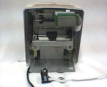
3 DISASSEMBLY AND REPLACEMNET 1 1. Remove front case. 2. Replace quartzose clock. 3. Replace Ribbon. 4. Remove Print Head. 5. Replace Fuse. 6. Remove back case. 7. Remove operation Panel block. 8. Remove the LCD. 9. Remove the Ribbon Drive Shaft. 10. Removing to LF reduction gears, mid gear and roller gear. 11. Removing the paper feed shaft and bearings. 12. Remove the cam gear, reduction gear, change gear and gear guide. 13. Remove the ribbon cam. 14. Remove the lead screw assembles, platen bearings and lead screw top. 15. Removing the card inlet and spacer and E-03&E-05 the sensor. 16. Removing the E-37 sensor. 17. Removing the E-30 sensor. 18. Removing the E-38 sensor. 19. Removing the switch lever and switch lever. 20. Remove the friction spring, friction shaft and friction roller. 21. Remove 2000UL PCB assembly. 22. Load NiCd battery.


4 1Remove front case Remove two screws M38 2.Two press place and push out direction 3. Remove front case


5 2. Replace quartzose Clock
 2.")


6 Remmove one screw ST37 (2-1) 2.Remove active cover( ) 3.Remove time face Acryl2-5 4.Remove second hand2-6 5.Remove minute hand2-7 6.Remove hour hand2-8 7.Remove one screw2-9 8.Remove quartzose clock2-10


7 3. Replace Ribbon Remove and discard two pin clip Pull the ribbon cassette by hand Load new Ribbon 4. Load two pin and clip and front case.


8 4. Remove Print Head
9 1.Remove the FPC guide using a standard type screwdriver.(4-2) 2.Disconnect the FPC cable from the connector (PCN8).(4-34-4) 3.Pull the head toward the front by hand Left it to remove.4-6


10 5. Replace Fuse Remove one screw M36(5-1) 2.Open the small back cover(5-2) 3.Remove the damage fuse(5-3) 4.Replace a new fuse into right place 5.Close the small back cover and install the screw(5-4)

 2.")


11 6. Remove back case Remove four screws M410(6-2) 2.Remove the back case by handand disconnect operation panel block cable from the connector on operation panel block.(6-36-4)


12 7. Remove operation Panel block Remove three screws ST Remove the operation panel block7-3

 2.")
 3.Remove two screws.(8-2) 4.")
13 8. Remove the LCD Disconnect the LCD cable from the connector (LCN10) on the 2000UL PCB assembly.(8-1) 2.Disconnect the LCD cable from the connector on the 2003A PCB assembly.(8-1) 3.Remove two screws.(8-2) 4.Remove the LCD.(8-3)


14 9. Remove the Ribbon Drive Shaft Remove the screw fixing the Ribbon Clutch Holding Plate Remove the Ribbon Drive shaft by hand.(9-3)

 2.")

 3.")
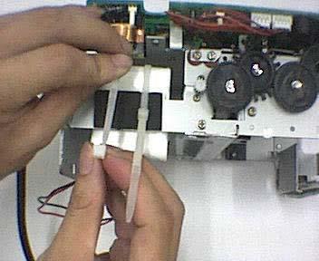
15 10. Removing to LF reduction gears, mid gear and roller gear Remove three snap rings with a standard type screwdriver.(10-3) 2.Pullthe two LF reduction gears out of the shaft (Inset a standard type screwdriver into the gap between the LF gear and frame, and lift the gear).(10-4) 3.Remove the mid gear in the same manner as shown second step. 4.Remove the roller gear in the same manner as shown second step.


16 11. Removing the paper feed shaft and bearings
17 1.Removing the LF Reduction gear.(11-1) 2.Removing the Roller gear.(11-2) 3.Turn the bearing with small pliers to match up the projections on the bearing with the notches in the frame.(11-3) 4.Remove the bearings from the paper feed shaft to outside of the frame (There are two bearings, on the right and left).(11-4) 5.More the paper feed shaft by hand.(11-5) 6.Detach it toward the front from inside the frame.(11-6)
 2.")


18 12. Remove the cam gear, reduction gear, change gear and gear guide Remove the motor gear.(12-1) 2.Remove one screw to remove the Lever Holding Spring(12-2) 3.Pull the cam gear out of the shaft, Inset a standard type screwdriver into the gap between the cam gear and frame, and left the cam gear. Be careful mot to press the screwdriver against the shaft from the side. 4.Remove the reduction gear in the same as shown in above step. The change gear and gear guide are also remove with the reduction gear.


19 13. Remove the ribbon cam Remove the snap ring with a standard type screwdriver.(13-2) 2.Pull the ribbon cam out of shaft (Inset a standard type screwdriver into the gap between the ribbon cam and frame, and lift the cam. Be careful not to press the screwdriver against the shaft from the side).(13-3)


20 14. Remove the lead screw assemble, platen bearings and lead screw top


21
 3.Remove the lead screw assemble by hand.(14-1014-11) 4.Turn the lead screw top to match up the projection on it with the notch in the carrier.")
22 Remove one screws.(14-3) 2. Remove platen bearing whirl stop screw from the right.( ) 3.Remove the LF gear and the motor gear and two screws to pull out the motor A.( ) 3.Remove the lead screw assemble by hand.( ) 4.Turn the lead screw top to match up the projection on it with the notch in the carrier. Pull the lead screw top below the carrier


23 15. Removing the card inlet and spacer and E-0305 the sensor
 3.")
24 20-7 Remove four screws fixing the card inlet.(20-1) 1. Remove the card inlet by hand.( ) 2. Press the hooks of the right and left sensors slightly outwards and pull out the E-0305 sensors. Be careful not to break the hooks.( ) 3. Remove two screws fixing the spacerand pull out the spacer.( )


25 16. Removing the E-37 sensor Remove two screws to take out of the sensor holding plate.( ) 2.Remove another two screws to take out the sensor.( )


26 17. Removing the E-30 sensor
27 1.Disconnect the sensor harness assembly from the connector(lcn3)on the 2000UL PCB assembly.(15-1) 2.Remove two screws to take out the screw holding plate.( ) 3.Remove another two screws to take out the sensor.( )


on")
")
28 18. Removing the E-38 Sensor Dissconnect the sensor harness assembly from the connector(lcn9)on the 2000UL PCB assembly. 2.Remove two screws(m38) to take out the sensor.


29 19. Removing the switch lever and switch lever Remove two screws (a) fixing Switch Lever 2.Pull the switch lever out of the snap of switch lever position accurately.


30 20. Remove the friction spring, friction shaft and friction roller
31 1. Remove two screws fixing the right and left friction springs to remove the friction springs. The friction shaft and friction roller are also removed.


32 21. Remove 2000UL PCB assembly

33 Disconnect all the sensor harness assembly, and LCD cable, and operation black cable, and motor block, and FPC cable from the connectors on the 2000UL PCB assembly Remove two screws Pull out the 2000UL PCB assembly by hand Solder down the power supply wire to pull out the 2000UL PCB assembly


34 22. Load NiCd battery


35 Place black sticker on the main body shelf. 2. Place white both sided sticker on the rechargeable battery. 3. Place rechargeable battery on the main body shelf. 4. Tighten the battery. 5. Tighten the inside wires.
36 PARTS LIST Acroprint ATR120 Time recorder BOM THE ELECTRON COMPONENT Name Mode Place In ATR120 P/N Remarks Multilayer Ceramic Capacitor 0.1uF/50V PC21 PC22 PC14 Multilayer Ceramic Capacitor 0.01uF/50V PC10 LC25 LC38 Multilayer Ceramic Capacitor 1000PF/50V PC8 PC18 LC29 LC30 LC36 Multilayer Ceramic LC26 LC28 LC37 LC39 LC40 100PF/50V Capacitor LC41 LC42 LC43 Ceramic Capacitor 0.1uF/50V PC19 PC23 Multilayer Ceramic Capacitor 18P/50V 5% LC33 Multilayer Ceramic Capacitor 15PF/50V 5% LC34 Multilayer Ceramic Capacitor 30PF/50V 5% LC31 LC32 Diode IN4007 PD2 PD3 PD4 PD5 PD6 PD7 PD8 PD11 SD3 Diode IN4148 LD11 LD12 LD13 PD9 16K 1/4W 1% PR13 18K 1/4W 1% LR39 1 M 1/4W 1% LR26 4.7K 1/4W 1% PR14 100K 1/4W 5% LR19 LR41 LR42 LR76 10K 1/4W 5% LR27 LR32 LR33 LR47 LR68 BR77 10R 1/4W 5% PR7 15K 1/4W 5% 1 K 1/4W 5% 2.2K 1/4W 5% LR49 LR20 LR22 LR24 LR28 LR30 LR70 PR2 LR45 LR46 LR48 LR50 LR52 LR53 LR54 LR55 LR56 LR57 LR58 LR59 LR60 LR61 LR62 LR63 LR64 LR65 LR66 LR67 PR11 PR15 LR21 LR23 LR25 LR29 LR31 LR69 22R 1/4W 5% PR3
37 Name Mode Place In ATR120 P/N Remarks D K 1/4W 5% LR18 33K 1/4W 5% PR9 PR10 620R 1/4W 5% LR37 LR38 LR44 LR51 LR71 820R 1/4W 5% PR8 9.1K 1/4W 5% LR40 LR72 LR73 LR74 Q5 Q6 Q7 Q8 Q9 Q10 Q11 Q12 Q UL PCB IC UC3842BN PU1 Opto-couple PC817 PU3 SCR TL431 PU2 IC TA7291 PU10 PU11 IC 78L05 PU4 IC 74HD LU5 PN NBE-065 IC HD74HC14P LU6 IC HD74HC244P LU8 LU9 IC UL N2003 LU7 MOSFET K2608 PQ1 Bridge-commuted KBL206 PD1 Dynatron C1815 Q3 Q4 Q15 Q17 BQ20 Dynatron C1015 Q18 Q19 X2 Capacitor 0.1UF/275V PC3 X2 Capacitor 0.33UF/275V PC1 Ceramic Disc Capacitor PC24 Polyester Film Capacitor 0.047UF/100V PC9 Aluminum Capacitor Aluminum Capacitor Aluminum Capacitor Aluminum Capacitor Aluminum Capacitor Electrolytic Electrolytic Electrolytic Electrolytic Electrolytic 1UF/50V PC12 10UF/16V LC35 47UF/25V PC7 PC16 PC17 100UF/25V PC UF/25V PC11
38 Name Mode Place In ATR120 P/N Remarks Aluminum Capacitor Electrolytic PC13 Aluminum Capacitor Electrolytic PC1 Neilsbed 2PIN 180 PCN1 Neilsbed 4PIN 180 LCN3 LCN4 LCN8 PCN9 Neilsbed 4PIN 90 LCN0 Neilsbed 8PIN 90 LCN5 Flex. PCB Socket 10PIN 180 LCN12 Flex. PCB Socket 12PIN 180 PCN7 Flex. PCB Socket 21PIN 180 LCN10 100R 1W 5 PR16 270R 1W 5 PR12 360R 1W 5 LR35 LR R 2W 5 PR1 51K 2W 5 PR5 270K 2W 5 PR6 Buzzer KC-1201 BZ1 Buzzer XHD RL1 Crystal KHZ LX1 Crystal 4.00MHZ LX2 CR2032 PBT1 Fuse DC12V 2A PF3 Fuse DC12V 1.5A PF1 Fuse AC240V 1A PF2 Fuse nip Line Filter UU9.8 30mH PLF1 Filter 47uH Choke Coil 15uH Choke Coil 1.5A 48mH PL1 Transformer EI-28 PT1 Tact Switch TS1102P RESET Mechanical switch SW/3P SW301 SW302 Switch SW/3P SW304
39 Radiating-flake Model E Flame Assembly P/N NBD Plate Soleplate P/N NBD Switch Lever P/N NB-008 Switch Lever B P/N NB-015 Switch Lever Support P/N NB-019 Paper Feed Shaft P/N NBD Friction Shaft P/N NBD Friction Roller P/N NB-034 Friction Spring P/N NBD Lever Holding Spring 0.4mm P/N NBD A Lever Holding Spring 0.2mm P/N NBD B Guide Pillar P/N NBD Platen Bearing P/N NBL P/N NB-048 Carrier P/N NB-002 Lead Screw Top P/N TW102 Platen P/N NBD FPC Guide P/N NBD Print Head P/N YZCP-100 Cassette Holding Plate R P/N NB-006 Ribbon Cam Spring P/N NBD Ribbon Drive Shaft P/N NB-005 Ribbon Clutch Gear P/N NB-028 Ribbon Clutch Spring P/N NBD Ribbon Clutch Holding Plate P/N NBD Carrier Auxiliary Board P/N NB-037 Reduction Gear P/N NB-029 Chang Gear P/N NB-032 Gear Guide P/N NB-037 Roller Gear P/N NB-003 Mid Gear P/N NB-004 LF Reduction(A) P/N NB-017 LF Reduction(B) P/N NB-039
40 Motor Gear P/N NB-035 Motor Gear P/N NB-011 Cam Gear P/N NB-033 Lead Screw Gear P/N NB-027 Ribbon Cam P/N NB-013/014 Card Guide(Left) P/N NB-009 Card Guide(Right) P/N NB-010 Card Inlet P/N NB-040 Bearing big P/N NB-018 Bearing small P/N NB-019 Motor(A) P/N TW-104 Motor(B) P/N TW-105 Motor Holding Plate P/N NBD Motor Block P/N NBE-090 E-0305Sensor SG-205 P/N NBE-091 E-30 Sensor SG-23FF P/N NBE-092 E-3738Sensor SG-289 P/N NBE-093 Sensor Signal Wire Sensor Signal Wire Tubing Sensor Holding Plate E-30 Sensor P/N NDB Sensor Holding Plate E-37 Sensor P/N NDB Power Supply Wire P/N NBE-094 Insulating Bushings 5P-4 P/N NBE-095 Insulating Bushings 3F-2 P/N NBE-096 LCD P/N CDCP-062 LCD Holding Plate P/N NBD LCD Cable 170mm P/N NBE-097 Operation Panel Block P/N AJCP-064 Operation Panel Block Cable P/N NBE-098 Cushion(#1) P/N DP-109 Cushion(#2) P/N DP-110 Cushion(#3) P/N DP-111 Cushion(#4) P/N DP-112
41 Cushion(#5) P/N DP-113 Red Cushion 1.0mm P/N DP-114 Red Cushion 1.6mm P/N DP-115 Snap Rings P/N DC-116 Snap Rings P/N ZC-117 Snap Rings P/N XC-118 Screws P/N NB-119 Screws Screws Screws M38 Phillips round head screws with Spring Washer P/N NB-120 P/N NB-121 P/N NB-122 Screws M38 Phillips round head screws with SPW P/N NB-123 Screws P/N NB-124 Screws P/N NB-125 Screws M4 10Phillips round head screws P/N NB-126 Screws M4 8 Phillips round head screws with SPWs P/N NB-127 Screws ST419 P/N NB-128 Snap rings NDB Nut M3 P/N NB-129 Nut M4 P/N NB-130 ABS765A P/N NB-044 ABS765A P/N NB-001 Explain Label P/N NB-131 Dust Cover ABS765A P/N NB-021 Keyboard film P/N NB-132 Front Case ABS765A P/N NB-045/049/046 Active Cover ABS765A P/N NB-042 Time Face Acryl P/N NB-043 Small Acryl P/N NB-041 Clock P/N NB-052 Rubber Cushion P/N NB-053 Cuprum Cushion P/N NB-054 Nut P/N NB-055 Hour Hand white ATR120 P/N NB-056 Minute Hand white ATR120 P/N NB-057
42 Second Hand white ATR120 P/N NB-058 Clock face Aluminum Board P/N NB-059 Cell 1.5V P/N NB-133 button P/N TW-107 Ribbon SDCP-101 Underlay P/N NB-060 Pin and Clip P/N TW-108 Label P/N NB-136 P/N NB-137 Notebook ATR120 P/N NB-138 Wall Map P/N NB-139 8# Bag P/N NB-140 0# Bag P/N NB-141 Bag P/N NB-142 Fix up Holding Plate P/N NBD Plastic Thimble P/N NB-143 battery 3V P/N NB-134 Carton ATR121 P/N NB-144 Carton ATR121 P/N NB-145 P/N NB-146 Time Card P/N NB-147 Serial Label P/N NB-148
43 P.C.B. CIRCIUT DIAGRAM
44 BELOW: TOP LAYER BOTTOM LAYER BOTTOM LAYOUT TOP LAYOUT
45
46
47
48
49 C.P.U BLOCK DIAGRAM AND PIN ASSIGNMENT <PORT LIST> 74HD port Name Function Description Logic 2 R70/AN0 IN NiCd battery change control signal 3 R71 IN Mechanical switches L 4 R72 IN Red/Black ribbon check switch L 5 R73 IN Head position check sensor(e-30) L 6 R80 IN Card right/back side check sensor H 7 R81 IN Card right/back side check sensor H 17 D0/INT0 IN Head feed encoder sensor input(e-38) 18 D1/INT1 IN Paper feed encoder sensor input(e-37) 19 D2 OUT H 20 D3 OUT Five sensors control H 21 D4 IN AC Failure detection signal H 22 D5 IN 5V monitoring H 23 D6 OUT Time signal control H 24~26 D7~D9 OUT Six key and jumper wire scan control L 27~28 D10~D11 OUT Six LED scan control L 29 R00 OUT Paper feed motor control(pulling) H 30 R01 OUT Paper feed motor control(ejection) H 31 R02 OUT Head feed motor control(changing red and black ribbons) H 32 R03 OUT Head feed motor control(head feed) H 33 R10 IN red or black ribbons control L 34 R11/EVND No use 35 R12/BUZZ OUT Piezoelectric buzzer control 36 R13 OUT Printer head pin1 H 37 R20 OUT Printer head pin2 H 38 R21 OUT Printer head pin3 H 39 R22 OUT Printer head pin4 H 40 R23 OUT Printer head pin5 H 41 R30 OUT Printer head pin6 H 42 R31 OUT Printer head pin7 H 43 R32 OUT Printer head pin8 H 44 R33 OUT Printer head pin9 H 45~48 R40~R43 OUT Step motor control 49~51 R50~R52 OUT Six LED SEG control H 52 R53 OUT Clock sensor control H 53~55 R60~R62 IN Six key and jumper wire control L 56 R63 IN Clock sensor input H 57~72 SEG17~SEG32 OUT LCD display SEG 73~76 COM1~COM4 OUT LCD display COM
50 <ELECTRONIC TIME RECORDER CONTROL PANE > Electronic Time Recorder Control Pane SW301 LCD (LCN10) SW30 SW30 OCS1 (4MHz) OCS2 ( KHz) CPU HD40489B33H ULN2003 KEY1~6 LED1~6 Printer PCN7 E-0305(LCN Q2 74HC244 E-37(LCN E-30(LCN3) Q3 E-38 (LCN BQ2 TA7291P Q4 Buzze r1 Q5~13 MOTOR (PCN8) AandB Buzzer2 DC12V
51
52 1Voltage check MEASUREMENT Note: Measurement with no load is possible. Measuring point Voltage Description 11VGND 11.0V5% AC plug should be connected 5VGND 5.0V5% AC plug should be connected 2Motor operation check (PCN8.1~4) Apply the voltages shown below to the terminals of the harness connected to connector PCN8 on the 2000UL PCB ass y to make sure that the motor runs properly. Motor Operation Applied voltage Pin 1(orange) Pin 2(green) Pin 3(red) Pin 4(green) LF Motor(A motor) Pulling 4~9V GND LF Motor(A motor) Ejection GND 4~9V CR Motor(B motor) Changing red and black ribbons.(continuous) ~9V GND CR Motor(B motor) Head feed GND 4~9V 3Head resistance measurement (PCN7.1~12) Measure the head resistance at the terminals of the harness connected to connector PCN7 on the 2000UL PCB ass y. Measuring point(pin NO. of PCN7) Resistances Open Short NoteIf the head resistance is less then the values shown abovethe head pin drive circuit may also be defectivereplace the head and repair the 2000UL PCB ass y. 4Sensors circuit There are five sensorstheir functions are show below: Name CPU port Functions E-03 R80 Detects the right-up edge of an inserted time card. E-05 R81 Detects the left-up edge of an inserted time card. E-37 D1 Detects the operating condition of the LF motor. E-38 D0 Detects the operating condition of the CR motor. E-30 R73 Check whether the head is at the home position(left end of the machine).
53 (LCN5.1~8) Measuring point (Pin NO.) Signal name Description Stand by Inserted time card and printing 1 E-03-E V or more0 2 E-03-C 5V 5V 3 E-03-A 10.2V or more 10.0V or more 4 E-03-K 9.5V or more 8.5V or more 5 E-05-E V or more0 6 E-05-C 5V 5V 7 E-05-A 9.5V or more 8.5V nor more 8 E-05-K 9.0V or more 7.5V or more E-37 sensor (LCN4.1~4) Measuring point (Pin NO.) Signal name Description Stand by Inserted time card and printing 10.2V or more 10.0V or more 9.5V or more 8.5V or more E-38 sensor (LCN9.1~4) Measuring point (Pin NO.) Signal name Description Stand by Inserted time card and printing 10.2V or more 10.0V or more 9.5V or more 8.5V or more E-30 sensor (LCN3.1~4) Measuring point (Pin NO.) Signal name Description Stand by Inserted time card and printing 10.2V or more 10.0V or more 9.5V or more 8.5V or more 4.0V or more04.0v or more0 or 04.0V or more0
54 The following table shows the operation modes and functions: Mode A B C D Operation AC power supply Printing battery Back light(led) Battery indicator CPU status Normal Power failure mode Power failure mode. Power failure mode. operation.. All where printing is Time is updated. Data Time is updated. Data functions are possiblesame operation issavedinthememory. issavedinthememory. valid. as in A mode. ON OFF OFF OFF Operable/dead Operable(guarantees Operable(does not Dead. Or, operable but mechanism operation) guarantees mechanism supplies voltage below operation) the rated value. Yes NO NO NO No display Full to half Should be replace. NO (flashes) Active mode Active mode Active mode Watch mode Watch mode Watch mode Watch mode 2000UL PCB Ass y (1) PCN1 Pin No. Signal name 1 NiCd Battery Output 2 GND <CONNECTOR PIN ASSIGHMENT> (2) LCN3 Pin No. Signal name (3)LCN4 Pin No. Signal name
55 (4)LCN9 Pin No. Signal name (5)LCN0 Pin No. Signal name 1 +5V 2 GND 3 Card insertion 4 Panelopen/close (6)LCN5 Pin No. Signal name Pin No. Signal name 1 E-03-E 5 E-05-E 2 E-03-C 6 E-05-C 3 E-03-A 7 E-05-C 4 E-03-K 8 E-05-K (7)LCN12 Pin No. Signal name Pin No. Signal name 1 R60 6 D9 2 R61 7 D10 3 R62 8 R50 4 D7 9 R51 5 D8 10 R52 (8)LCN10 Pin No. Signal name Pin No. Signal name 1 SEG17 12 SEG28 2 SEG18 13 SEG29 3 SEG19 14 SEG30 4 SEG20 15 SEG31 5 SEG21 16 SEG32 6 SEG22 17 COM1 7 SEG23 18 COM2 8 SEG24 19 COM3 9 SEG25 20 COM4 10 SEG26 21 No use 11 SEG27
56 (9)PCN8 Pin No. Signal name 1 R00(A motor) 2 R01(A motor) 3 R02(B motor) 4 R03(B motor) (10).PCN7 Pin No Signal name. Pin No Signal name 1 GND 7 11V 2 PIN4 8 11V 3 PIN6 9 PIN3 4 PIN2 10 PIN9 5 PIN8 11 PIN5 6 PIN1 12 PIN7
ELECTRONIC TIME RECORDER
 ELECTRONIC TIME RECORDER TO PLACE AN ORDER CALL: 866-487-475 OR VISIT: WWW.TIMECLOCKEXPERTS.COM 06-097-000 Rev. B 5640 Departure Drive Raleigh, NC 766 Service Manual CONTENTS. OUTLINE.... BLOCK DIAGRAM...
www MK-Electronic de EPSON LQ2170 Spares Guide Version 3 Page 1
 REF PART NO DESCRIPTION REMARKS QTY 100 1025018 HOUSING ASSY., LOWER 1 101 1025039 COVER, FRONT 1 102 1025041 HOUSING, UPPER 1 103 1025027 COVER, PRINTER, REAR 1 104 1025024 COVER ASSY., PRINTER 1 105
M-8485Se Printer Standard Unit
 M-885Se Printer Standard Unit Spare Parts List Page - P/N 900076 Rev.C SATO Industrial Bar Code Printers Table of Contents M-885Se Spare Parts List Page Frame Assembly...3 Print Head Assembly...9 Ribbon
FACSIMILE EQUIPMENT PARTS REFERENCE LIST. MODEL: MFC Pro-700C. www MK-Electronic de
 FACSIMILE EQUIPMENT PARTS REFERENCE LIST MODEL: MFC Pro-700C NOTES FOR USING THIS PARTS REFERENCE LIST 1. In the case of ordering parts, it needs mentioning the following items: (1) Code (2) Q' ty (3)
www MK-Electronic de EPSON LQ670 Page 1 of 14
 REF. PART NO. REMARKS QTY DESCRIPTION 100 1032438 1 HOUSING UPPER 101 1032439 1 COVER PRINTER 102 1034102 1 HOUSING ASSY. LOWER 103 1034610 1 LOGO PLATE 104 1034101 1 COVER ASSY. PRINTER; B 105 1034103
FACSIMILE EQUIPMENT PARTS REFERENCE LIST. MODEL:FAX1270e / FAX1575MC (For U.S.A. / Canada )
") FACSIMILE EQUIPMENT PARTS REFERENCE LIST MODEL: / 1575MC (For U.S.A. / Canada ) Copyright Brother 2004 All rights reserved No part of this publication may be reproduced in any form or by any means without
FACSIMILE EQUIPMENT PARTS REFERENCE LIST MODEL: / 1575MC (For U.S.A. / Canada ) Copyright Brother 2004 All rights reserved No part of this publication may be reproduced in any form or by any means without
FACSIMILE EQUIPMENT PARTS REFERENCE LIST. MODEL: FAX4100 / 4750e / 5750e MFC8500 (For U.S.A. / Canada )
") FACSIMILE EQUIPMENT PARTS REFERENCE LIST MODEL: FAX4100 / 4750e / 5750e MFC8500 (For U.S.A. / Canada ) Copyright Brother 2001 All rights reserved No part of this publication may be reproduced in any form
FACSIMILE EQUIPMENT PARTS REFERENCE LIST MODEL: FAX4100 / 4750e / 5750e MFC8500 (For U.S.A. / Canada ) Copyright Brother 2001 All rights reserved No part of this publication may be reproduced in any form
MODEL: FAX4100New / 4100e / FAX4750eNew / 5750eNew
 FACSIMILE EQUIPMENT PARTS REFERENCE LIST MODEL: FAX4100New / 4100e / FAX4750eNew / 5750eNew (For U.S.A. / Canada) Copyright Brother 2003 All rights reserved No part of this publication may be reproduced
FACSIMILE EQUIPMENT PARTS REFERENCE LIST MODEL: MFC 7150C/MFC 7160C
 FACSIMILE EQUIPMENT PARTS REFERENCE LIST MODEL: MFC 7150C/MFC 7160C Enable Thumbnails Enable Book Marks Exit Acrobat Viewer Copyright Brother 1998 All rights reserved No part of this publication may be
IV-11 VFD tube clock Assembly instructions v1.2.2
 IV-11 VFD tube clock Assembly instructions v1.2.2 Designer: Website: E-mail: Yan Zeyuan. China http://www.nixieclock.org yanzeyuan@qq.com 2017-01-26 NCH Attention Attention: Warning: Warning: Warning:
MODEL: NV900D Published: Jan.,2008 Revised: Jan.,2017
 MODEL: NV900D Published: Jan.,2008 Revised: Jan.,2017 MODEL LIST Model Countries (Added Date) NV900D USA, CAN, CHL, BRA120V, BRA220V (Feb / 2011) Country Code & Abbreviation of Country Name Meaning of
INSTALLATION INSTRUCTIONS
 INSTALLATION INSTRUCTIONS Accessory REMOTE CONTROL Application 2008 CR-V Publications No. AII 35843-38422 Issue Date DEC 2007 PARTS LIST Caution label Remote Engine Starter Kit P/N 08E91-E22-100B Transmitter
Schematic VCC J1 1 CON1 +5V D26 D25 D7 D8 D9 D10 D11 D12 D19 D20 D21 D22 D23 D24 D1 D2 D3 D4 D5 D6 D13 D14 D15 D16 D17 D18 R4 100R R2 100R R6 100R
 Schematic +5V S D1 D2 D3 D4 D5 D6 D7 D8 D9 D10 D11 D12 D19 D20 D21 D22 D23 D24 D13 D14 D15 D16 D17 D18 D25 D26 R1 4K7 R2 100R Q1 9014-PNP C1 47uF R3 4K7 R4 100R Q2 9014-PNP C2 47uF R5 4K7 R6 100R Q3 9014-PNP
Repair Parts List WASHER MODEL NUMBER MFR35PCAVS. When requesting service or ordering parts, always provide the following information:
 Repair Parts List WASHER MODEL NUMBER MFR35PCAVS When requesting service or ordering parts, always provide the following information: - Product Type - Part Number - Model Number - Part Description 2005
INSTALLATION INSTRUCTIONS
 INSTALLATION INSTRUCTIONS Accessory REMOTE CONTROL ENGINE STARTER Application 2010 CR-V Publications No. AII 42612-42916 Issue Date OCT 2009 PARTS LIST Remote Engine Starter Unit Kit P/N 08E91-E22-101B
Parts List. For printer model: TH208 PN: (A)
") Parts List For printer model: TH208 www.satoamerica.com PN: 9001235(A) SATO America, Inc. 10350A Nations Ford Road Charlotte, NC 28273 Main Phone: (704) 644-1650 Technical Support: (704) 644-1660 Technical
Parts List For printer model: TH208 www.satoamerica.com PN: 9001235(A) SATO America, Inc. 10350A Nations Ford Road Charlotte, NC 28273 Main Phone: (704) 644-1650 Technical Support: (704) 644-1660 Technical
P-touch SERVICE MANUAL. MODEL: PT-1300 (For U.S.A.) LS-7 (Panduit ) REVISED
 LS-7 (Panduit ) REVISED") P-touch SERVICE MANUAL MODEL: PT-300 (For U.S.A.) LS-7 (Panduit ) REVISED PREFACE This publication is a service manual covering the specifications, theory of operation, disassembly/reassembly procedure,
P-touch SERVICE MANUAL MODEL: PT-300 (For U.S.A.) LS-7 (Panduit ) REVISED PREFACE This publication is a service manual covering the specifications, theory of operation, disassembly/reassembly procedure,
Service Manual - CD-303MP
 R Service Manual - CD-303MP CD-303MP WiWi Industries Limited Engineering Department Bill of Materials 1 001-0000S-B90 P.C.B FILTER BOX 1 2 001-3900S-P90 P.C.B CD-3900 MAIM BOARD 1 3 002-01140-A00 I.C LA1140
Total solder points: 126 Difficulty level: beginner advanced POWER DIMMER 230V) K8038 ILLUSTRATED ASSEMBLY MANUAL
 K8038 ILLUSTRATED ASSEMBLY MANUAL") Total solder points: 126 Difficulty level: beginner 1 2 3 4 5 advanced POWER DIMMER (1KW @ 230V) K8038 NOISE SUPPRESSED ACCORDING TO EN55015 Class microcontroller high power dimmer with non volatile memory
Total solder points: 126 Difficulty level: beginner 1 2 3 4 5 advanced POWER DIMMER (1KW @ 230V) K8038 NOISE SUPPRESSED ACCORDING TO EN55015 Class microcontroller high power dimmer with non volatile memory
IDC-136II-KIT 136kHz DC RX Assembly Guide
 IDC-136II-KIT 136kHz DC RX Assembly Guide ICAS Enterprises May 2 nd,2016 The IDC-136II-KIT is a 136kHz direct conversion receiver. Most of the SDR software can be used with this receiver. It is quite easy
SERVICE MANUAL MODEL: PT-2700/2710
 P-touch SERVICE MANUAL MODEL: PT-2700/2710 PREFACE This publication is a service manual covering the specifications, theory of operation, disassembly/reassembly procedure, and troubleshooting the Brother
(SHADED ROWS INDICATE MAJOR ITEMS) 1 REF PART NO. REMARKS QTY DESCRIPTION
 1 REF PART NO. REMARKS QTY DESCRIPTION") NB THIS SPARES GUIDE IS PROVISIONAL AND SUBJECT TO AMENDMENT (SHADED ROWS INDICATE MAJOR ITEMS) Page 1 REF PART NO. REMARKS QTY DESCRIPTION 100 1036887 1 HOUSING 101 1033230 5 FOOT 102 1036888 1 COVER,
NB THIS SPARES GUIDE IS PROVISIONAL AND SUBJECT TO AMENDMENT (SHADED ROWS INDICATE MAJOR ITEMS) Page 1 REF PART NO. REMARKS QTY DESCRIPTION 100 1036887 1 HOUSING 101 1033230 5 FOOT 102 1036888 1 COVER,
TTP-245 Plus / TTP-343 Plus TTP-247 / TTP-345
 TTP-245 Plus / TTP-343 Plus TTP-247 / TTP-345 THERMAL TRANSFER / DIRECT THERMAL BAR CODE PRINTER PARTS LIST TTP-245 Plus / TTP-343 Plus / TTP-247 / TTP-345 Bar Code Printer Parts List Part List... 2 1
Total solder points: 93 Difficulty level: beginner advanced 10 LED MONO VU METER K4304 ILLUSTRATED ASSEMBLY MANUAL
 Total solder points: 93 Difficulty level: beginner 1 2 3 4 5 advanced 10 LED MONO VU METER K4304 Add a visual readout to your existing or new equipment. ILLUSTRATED ASSEMBLY MANUAL H4304IP-1 Features &
INSTALLATION INSTRUCTIONS
 INSTALLATION INSTRUCTIONS Accessory REMOTE ENGINE STARTER SYSTEM Application 2010 CIVIC 4-DOOR Publications No. AII 42460 Issue Date AUG 2009 PARTS LIST Remote Engine Starter Unit Kit P/N 08E91-E22-100B
PRELIMINARY INSTALLATION INSTRUCTIONS. Remote Engine Starter Attachment Kit P/N 08E92-SNA-100B
 INSTALLATION INSTRUCTIONS Accessory Application Publications No. REMOTE ENGINE STARTER SYSTEM 2008 CIVIC 2-DOOR AII 38215 Issue Date OCT 2007 PARTS LIST Remote Engine Starter Unit Kit P/N 08E91-E22-100B
MFR35MCATS : 01 - CONTROL PANEL (MC) [1/25] Ref # Part Number Qty. Description PLATE, BACK-UP (COIN METER) PANEL, CONTROL 3
![MFR35MCATS : 01 - CONTROL PANEL (MC) [1/25] Ref # Part Number Qty. Description PLATE, BACK-UP (COIN METER) PANEL, CONTROL 3](/thumbs/83/88605672.jpg "MFR35MCATS : 01 - CONTROL PANEL (MC) [1/25] Ref # Part Number Qty. Description PLATE, BACK-UP (COIN METER) PANEL, CONTROL 3") MFR35MCATS : 01 - CONTROL PANEL (MC) [1/25] Page 1 of 50 MFR35MCATS : 01 - CONTROL PANEL (MC) [1/25] Ref # Part Number Qty. Description 1 23001039 1 PLATE, BACK-UP (COIN METER) 2 23001489 1 PANEL, CONTROL
MFR35MCATS : 01 - CONTROL PANEL (MC) [1/25] Page 1 of 50 MFR35MCATS : 01 - CONTROL PANEL (MC) [1/25] Ref # Part Number Qty. Description 1 23001039 1 PLATE, BACK-UP (COIN METER) 2 23001489 1 PANEL, CONTROL
DRAWING NUMBER: GK-191-P-200-2C
 PARTS BREAK DOWN FOR A RIGID KAT LOWER HOUSING ASSEMBLY DRAWING NUMBER: GK-9-P-200-2C GK-7-005 KAT LOWER HOUSING 2 GK-7-02 WHEEL ADJUSTMENT SCREW 3 GK-0-062 3/4-6UNC HEX HEAD JAM NUT 4 GK-7-02 WHEEL ADJUSTMENT
PARTS LIST FOR VIPER VIPER
 P-336 P-336 PARTS LIST FOR P-336-A P-336-A ILLUSTRATION OF SUB-ASSEMBLIES 6 3 1 5 2 4 P-336-A.1 P-336-A.1 For Codes: 10597 to 10635 Do Not use this Parts List for a machine if its code number is not listed.
BUMP AND SPIN KIT ESSENTIAL INFORMATION. Version 1.0 PROGRAM AND DESIGN YOUR OWN BUGGY WITH THIS
 ESSENTIAL INFORMATION BUILD INSTRUCTIONS CHECKING YOUR PCB & FAULT-FINDING MECHANICAL DETAILS HOW THE KIT WORKS PROGRAM AND DESIGN YOUR OWN BUGGY WITH THIS BUMP AND SPIN KIT Version 1.0 Build Instructions
PARTS REFERENCE LIST MODEL: EM-530 / 630
 PARTS REFERENCE LIST MODEL: EM-530 / 630 NOTES FOR USING THIS PARTS REFERENCE LIST 1. In the case of ordering parts, it needs mentioning the following items: [ Example ] (1) Code (2) Q'ty (3) Description
INSTALLATION INSTRUCTIONS
 INSTALLATION INSTRUCTIONS Accessory REMOTE CONTROL Application 2011 ODYSSEY (EXCEPT LX) Publications No. AII 43923 Issue Date SEP 2010 PARTS LIST Remote Control Engine Starter Unit Kit P/N 08E91-E22-101A
CONTENTS (1) PRINCIPAL PARTS... 2 (2) UPPER SHAFT AND NEEDLE BAR... 4 (3) FEED MECHANISM... 6 (4) ROTARY HOOK AND THREAD GUIDE...
 PRINCIPAL PARTS... 2 (2) UPPER SHAFT AND NEEDLE BAR... 4 (3) FEED MECHANISM... 6 (4) ROTARY HOOK AND THREAD GUIDE...") 6. 1998. CONTENTS (1) PRINCIPAL PARTS... 2 (2) UPPER SHAFT AND NEEDLE BAR... 4 (3) FEED MECHANISM... 6 (4) ROTARY HOOK AND THREAD GUIDE... 8 (5) LAMP, MAIN PC BOARD ASSEMBLY AND MOTOR UNIT... 10 (6) ACCESSORY...
6. 1998. CONTENTS (1) PRINCIPAL PARTS... 2 (2) UPPER SHAFT AND NEEDLE BAR... 4 (3) FEED MECHANISM... 6 (4) ROTARY HOOK AND THREAD GUIDE... 8 (5) LAMP, MAIN PC BOARD ASSEMBLY AND MOTOR UNIT... 10 (6) ACCESSORY...
Oil Cooler AKZ328-D142 PL
 Oil Cooler PL-1009-15 1 2 Parts Parts Name Drwg. Parts Model & Specifi cation A1 A 1250093 SWING COMPRESSOR 1YC23HXD 1 M2C A2 0401393 RUBBER BUSH/ LEAD WIRE W443132-2 1 A4 390204 NUT WITH WASHER R4911377-1
MODEL: PE770 DZ820E SB7900E NV770E
 MODEL: PE770 DZ820E SB7900E NV770E Published: Jul.,2009 Revised: Nov.,2017 MODEL LIST Model Countries (Added Date) PE770 USA, ARG, PRY, BRA120V, BRA220V (Feb / 2011) PE770 AUS&NZL (Jul / 2012) DZ820E USA
INSTALLATION INSTRUCTIONS
 INSTALLATION INSTRUCTIONS Accessory REMOTE CONTROL Application 2012 ODYSSEY (EXCEPT LX) Publications No. AII 46745 Issue Date SEP 2011 PARTS LIST Remote Control Engine Starter Unit Kit P/N 08E91-E22-101A
802C System Controller Original and SMD Version
 802C System Controller Original and SMD Version Units with serial numbers beginning with 100000 are the original 802C's. Units with serial numbers beginning with 200000 are the new SMD 802C's. 1997 Bose
MODEL: CS6000 CS6000i BC2500 RS260
 MODEL: CS6000 CS6000i BC2500 RS260 Published: Sep.,2005 Revised: Mar.,2012 MODEL LIST Model Countries (Added Date) CS6000 CAN (Jan / 2011) CS6000i USA, ARG, PRY, BRA, BRA220V (Jan / 2011) BC2500 DEU&AUT,
Repair Parts List WASHER MODEL NUMBER MFR35MCATS. When requesting service or ordering parts, always provide the following information:
 Repair Parts List WASHER MODEL NUMBER MFR35MCATS When requesting service or ordering parts, always provide the following information: - Product Type - Part Number - Model Number - Part Description 2005
MODEL: ES2000/ES2000T/ES2010/ES2020 CE4000/CE5000 CS770 XR6600 COMFORT40E JS50E
 MODEL: ES2000/ES2000T/ES2010/ES2020 CE4000/CE5000 CS770 XR6600 COMFORT40E JS50E Published: Sep.,2005 Revised: Mar.,2017 MODEL LIST Model Countries (Added Date) ES2000 USA, CHL, GUF, BEL&FRA&NLD, KOR (Jan
Total solder points: 187 Difficulty level: beginner advanced. Code lock K6400 ILLUSTRATED ASSEMBLY MANUAL
 Total solder points: 187 Difficulty level: beginner 1 2 3 4 5 advanced Code lock K6400 Ged rid of those old fashioned keys ILLUSTRATED ASSEMBLY MANUAL H6400IP-2 Features & Specifications Features: More
MODEL: NQ1300PRW NQ1300
 MODEL: NQ1300PRW NQ1300 Published: Oct.,2014 Revised: Feb.,2018 MODEL LIST Model Countries (Added Date) NQ1300PRW USA (Oct / 2014) NQ1300 CAN, ARG, CHL, PRY, BRA (Oct / 2014) Country Code & Abbreviation
SKC400U SLIDING GATE OPENER OWNER S MANUAL
 SKC400U SLIDING GATE OPENER OWNER S MANUAL IMPORTANT SAFTEY INFORMATION Installing the SKC400U Gate Opener requires wiring of standard 110V electrical lines. This should only be performed by a trained
INSTALLATION INSTRUCTIONS
 INSTALLATION INSTRUCTIONS Accessory Application Publications No. REMOTE CONTROL 2009 MDX BII 40030 Issue Date JULY 2008 PARTS LIST Remote Engine Starter Unit Kit P/N 08E91-E22-200B Remote Control Engine
1 HP Ersatzteile für LaserJet 1005
 HP Ersatzteile für LaserJet 00 Paper Tray Parts RG0-0-000CN RG0-0-000CN Printer input paper tray assembly - Includes bottom tray, blue paper length adjustment lever, and extension arm (Does NOT include
TOSHIBA Thermal Printer B-852-R SERIES. Maintenance Manual. Document No. EO Original Mar., 2006 (Revised ) PRINTED IN JAPAN
 PRINTED IN JAPAN") TOSHIBA Thermal Printer B-852-R SERIES Maintenance Manual Original Mar., 2006 (Revised ) Document No. EO18-33018 PRINTED IN JAPAN EO18-33018 TABLE OF CONTENTS Page 1. UNPACKING --------------------------------------------------------------------------------------------1-1
TOSHIBA Thermal Printer B-852-R SERIES Maintenance Manual Original Mar., 2006 (Revised ) Document No. EO18-33018 PRINTED IN JAPAN EO18-33018 TABLE OF CONTENTS Page 1. UNPACKING --------------------------------------------------------------------------------------------1-1
INSTALLATION INSTRUCTIONS
 INSTALLATION INSTRUCTIONS Accessory REMOTE CONTROL Application Publications No. 2009 ACCORD AII 39977-40931 4-DOOR Issue Date (A/T ONLY) NOV 2008 PARTS LIST Remote Engine Starter Unit Kit P/N 08E91-E22-100A
INSTALLATION INSTRUCTIONS
 INSTALLATION INSTRUCTIONS Accessory REMOTE CONTROL Application 2014 TSX (L4) Publications No. BII 50198 Issue Date SEPT 2013 PARTS LIST Remote Engine Starter Unit Kit P/N 08E91-TK4-200A Fuse label Transmitter
QY8-31D3-000 COPYRIGHT 2007 CANON INC. CANON MP N
 MP610 REVISION 0 2180B001AA 2180B002AA 2180B003AA 2180B006AA 2180B007AA 2180B008AA 2180B009AA 2180B011AA 2180B012AA 2180B013AA 2180B014AA 2180B016AA MP610 / 100V(JP) MP610 / 120V(US) MP610 / 120V(CA) MP610
INSTALLATION INSTRUCTIONS
 INSTALLATION INSTRUCTIONS Accessory REMOTE CONTROL Application 2012 CR-V Publications No. AII 12085 Issue Date DEC 2011 PARTS LIST Remote Control Engine Starter Unit Kit P/N 08E91-E22-101A Accessory User
INSTALLATION INSTRUCTIONS
 INSTALLATION INSTRUCTIONS Accessory REMOTE CONTROL Application 2008 ACCORD 4-DOOR Publications No. AII 35365 Issue Date AUG 2007 PARTS LIST U Accessory User s Information Manual Remote Engine Starter Unit
FACSIMILE EQUIPMENT PARTS REFERENCE LIST. MFC4550/6550MC/7550MC (For U.S.A/Canada/S. America) Enable Thumbnails. Enable Book Marks.
 Enable Thumbnails. Enable Book Marks.") FACSIMILE EQUIPMENT PARTS REFERENCE LIST : FAX3550 MFC4550/6550MC/7550MC (For U.S.A/Canada/S. America) Enable Thumbnails Enable Book Marks Exit Acrobat REF.NO. CODE Q'TY DESCRIPTION REMARKS 1 1. DRIVE
FACSIMILE EQUIPMENT PARTS REFERENCE LIST : FAX3550 MFC4550/6550MC/7550MC (For U.S.A/Canada/S. America) Enable Thumbnails Enable Book Marks Exit Acrobat REF.NO. CODE Q'TY DESCRIPTION REMARKS 1 1. DRIVE
FACSIMILE EQUIPMENT PARTS REFERENCE LIST. MODEL: DCP8040 / 8045D MFC8440 / 8640D / 8840D / 8840DN (For U.S.A / Canada / Brazil)
") FACSIMILE EQUIPMENT PARTS REFERENCE LIST MODEL: DCP8040 / 8045D MFC8440 / 8640D / 8840D / 8840DN (For U.S.A / Canada / Brazil) Copyright Brother 2004 All rights reserved No part of this publication may
FACSIMILE EQUIPMENT PARTS REFERENCE LIST MODEL: DCP8040 / 8045D MFC8440 / 8640D / 8840D / 8840DN (For U.S.A / Canada / Brazil) Copyright Brother 2004 All rights reserved No part of this publication may
Home Sewing Machine PARTS REFERENCE LIST. MODEL: NC21-S2, S3 Model CS8000 Series CS8100 Series
 Home Sewing Machine PARTS REFERENCE LIST MODEL: NC21-S2, S3 Model CS8000 Series CS8100 Series CONTENTS (1) PRINCIPAL PARTS... 2 (2) UPPER SHAFT / NEEDLE BAR, PRESSER MECHANISM... 6 (3) FEED, ROTARY HOOK
SMF / DSF / DTF SMF / DSF / DTF 200
 2006 SMF / DSF / DTF 200 1 The drawings in this parts book have been scaled so that parts can be easily recognized. 1 CYLINDER ASSY 2 CYLINDER ASSY Ref # Part # Description 1 410 0001A CYLINDER HEAD COVER
MODEL: PE430 PE500 NV90E HE1 PE525
 MODEL: PE430 PE500 NV90E HE1 PE525 Published: Oct.,2008 Revised: Mar.,2017 MODEL LIST Model Countries (Added Date) NV90E IND (May / 2011) HE1 USA (Jul / 2011) PE500 USA (Nov / 2011) NV90E UK&IRE (May /
FACSIMILE EQUIPMENT PARTS REFERENCE LIST. MODEL: MFC8220 (For U.S.A / Canada)
") FACSIMILE EQUIPMENT PARTS REFERENCE LIST MODEL: MFC8220 (For U.S.A / Canada) Copyright Brother 2004 All rights reserved No part of this publication may be reproduced in any form or by any means without
FACSIMILE EQUIPMENT PARTS REFERENCE LIST MODEL: MFC8220 (For U.S.A / Canada) Copyright Brother 2004 All rights reserved No part of this publication may be reproduced in any form or by any means without
PARTS LIST / TECHNICAL GUIDE
 PARTS LIST / ANALOGUE SOLAR [SPECIFICATIONS] Item Cal. No. V172A/V174A V172A V174A 3 hands (hour, minute and small second hands) 3 hands (hour, minute and small second hands), 24-hour indicator Diameter:
FlexJet Carriage Circuit Board (PCB) Replacement
 Replacement") P/N: 111484 R0 14140 NE 200th St. Woodinville, WA. 98072 PH: (425) 398-8282 FX: (425) 398-8383 ioline.com FlexJet Carriage Circuit Board (PCB) Replacement Notices: Warning! Ensure that all AC power cables
P/N: 111484 R0 14140 NE 200th St. Woodinville, WA. 98072 PH: (425) 398-8282 FX: (425) 398-8383 ioline.com FlexJet Carriage Circuit Board (PCB) Replacement Notices: Warning! Ensure that all AC power cables
openqrp Transceiver Parts List By Functional Section 1/11/2014 Using openqrp PC Board Rev D, 40M Version
 openqrp Transceiver Parts List By Functional Section 1/11/2014 Using openqrp PC Board Rev D, 40M Version Section 1 AGND Schematic Page 2 R37 [I8] 10K 1/8W Resistor (Brown Black Orange) R38 [J9] C80 [J9]
ASTRO FF-14NW & FF-14NEW Friction Feeder
 ASTRO FF-14NW & FF-14NEW Friction Feeder PARTS CATALOG This manual is intended solely for the use and information of Astro Machine Corp., its designated agents, customers, and their employees. The information
April 24, 2013 Revision 0. Staple Finisher-R1 Service Manual
 1 2 3 4 5 6 April 24, 2013 Revision 0 Staple Finisher-R1 Service Manual 0 0-2 Application This manual has been issued by Canon Inc. for qualified persons to learn technical theory, installation, maintenance,
GCE-780MPT. Service Manual - GCE-780MPT
 GCE-780MPT Service Manual - GCE-780MPT 1 001-3896S-N50 P.C.B CD-3896 RDS MAIN 1 2 001-0000S-B90 P.C.B FILTER BOX 1 3 001-3896S-A60 P.C.B CD-3896 LAMP 1 4 001-3896S-B10 P.C.B CD-3896 SWITCH SW-A 1 5 001-3896S-B11
AstroJet TM 1000/1000P Inkjet Printer. Parts Manual
 AstroJet TM 1000/1000P Inkjet Printer Parts Manual This manual is intended solely for the use and information of Astro Machine Corp., its designated agents, customers, and their employees. The information
CONTENTS (1) PRINCIPAL PARTS... 2 (2) UPPER SHAFT AND NEEDLE BAR... 4 (3) FEED MECHANISM... 8 (4) ROTARY HOOK, THREAD GUIDE AND THREAD CUTTING...
 PRINCIPAL PARTS... 2 (2) UPPER SHAFT AND NEEDLE BAR... 4 (3) FEED MECHANISM... 8 (4) ROTARY HOOK, THREAD GUIDE AND THREAD CUTTING...") 7. 2001. CONTENTS (1) PRINCIPAL PARTS... 2 (2) UPPER SHAFT AND NEEDLE BAR... 4 (3) FEED MECHANISM... 8 (4) ROTARY HOOK, THREAD GUIDE AND THREAD CUTTING...10 (5) LAMP, MAIN PC BOARD ASSEMBLY AND MOTOR UNIT..12
7. 2001. CONTENTS (1) PRINCIPAL PARTS... 2 (2) UPPER SHAFT AND NEEDLE BAR... 4 (3) FEED MECHANISM... 8 (4) ROTARY HOOK, THREAD GUIDE AND THREAD CUTTING...10 (5) LAMP, MAIN PC BOARD ASSEMBLY AND MOTOR UNIT..12
ASTRO ATS-9900 TABBER, LABELER, AND STAMP AFFIXER. Parts Manual
 ASTRO ATS-9900 TABBER, LABELER, AND STAMP AFFIXER Parts Manual This manual is intended solely for the use and information of Astro Machine Corp. its designated agents, customers, and their employees. The
Brother Printer PARTS REFERENCE LIST MODEL:HL-S7000DN
 Brother Printer PARTS REFERENCE LIST MODEL:HL-S7000DN Read this list thoroughly before maintenance work. Keep this list in a convenient place for quick and easy reference at all times. September 2012 PL-PRN33
EAGLE 35, 65,105 Parts List
 EAGLE 35, 65,105 Parts List GBC IS AN ACCO BRANDS COMPANY 8.0 PARTS LIST All parts in each illustration are keyed with an index number for reference to the respective part number, part name, and quantity
Spare Parts List. Edition 10/07
 Spare Parts List Edition 10/07 Spare Parts List for the following products Table of Contents PRODUCT NUMBER CATALOG NUMBER PRODUCT DESCRIPTION 103957 BP-IP300 BRADY IP PRINTER - 300DPI STANDARD 103958
INSTALLATION INSTRUCTIONS
 INSTALLATION INSTRUCTIONS Accessory REMOTE CONTROL Application Publications No. 2012 ACCORD AII 46522 2-DOOR Issue Date (A/T ONLY) AUG 2011 PARTS LIST Remote Engine Starter Unit Kit P/N 08E91-E22-101A
SERVICE MANUAL MODEL: PT-9500PC
 SERVICE MANUAL MODEL: PT-9500PC SERVICE MANUAL MODEL: PT-9500PC PREFACE This publication is a service manual covering the specifications, theory of operation, disassembly/reassembly procedure, and troubleshooting
Better Bagger TM. Service Manual. 10-March
 Better Bagger TM 900e Service Manual 10-March-2005 www.betterpackages.com CONTENTS Parts list with reorder numbers. Page 1 Parts Identification Photographs Pages 2-4 Service Instruction Pages 5-10 The
CM Lodestar Electric Chain Hoist Electrical Parts List
 CM Lodestar Electric Chain Hoist Electrical Parts List MODELS Key No. Part Name No. Req'd A, A-2, AA, AA-2, B, B-2 C, C-2, E, E-2, F, F- 2, H & H-2 J, J-2, JJ, JJ-2, L, L-2, LL, LL-2, R, R- 2, RR, RR-2,
READ THIS FIRST. For questions or help with this product contact Tech Support at (570) or
 or") The following changes were made to this machine since the owner's manual was printed: Obtained CSA certification meeting CSA C22.2 #105-1953 and UL 987-7th standards. Changed transformer, contactors, overload
The following changes were made to this machine since the owner's manual was printed: Obtained CSA certification meeting CSA C22.2 #105-1953 and UL 987-7th standards. Changed transformer, contactors, overload
01 CYLINDER HEAD COVER 4 02 CRANKSHAFT, PISTON 6 03 FAN, AIR SHROUD 8 04 OIL PUMP (EPA) REED VALVE, AIR CLEANER CARBURETOR 14
 REED VALVE, AIR CLEANER CARBURETOR 14") Parts Manual 1 2 CONTENTS PAGE 01 CYLINDER HEAD COVER 4 02 CRANKSHAFT, PISTON 6 03 FAN, AIR SHROUD 8 04 OIL PUMP (EPA) 10 05 REED VALVE, AIR CLEANER 12 06 CARBURETOR 14 07 EXHAUST 16 08 CRANKCASE 18 09
Parts Manual 1 2 CONTENTS PAGE 01 CYLINDER HEAD COVER 4 02 CRANKSHAFT, PISTON 6 03 FAN, AIR SHROUD 8 04 OIL PUMP (EPA) 10 05 REED VALVE, AIR CLEANER 12 06 CARBURETOR 14 07 EXHAUST 16 08 CRANKCASE 18 09
PARTS CATALOGUE / TECHNICAL GUIDE
 PARTS CATALOGUE / TECHNICAL GUIDE [SPECIFICATIONS] Item Movement Cal. No. V653B Movement size Outside diameter Casing diameter Height ø29.5 mm 26.0 mm between 3 o clock and 9 o clock sides ø28.8 mm 3.7
INSTALLATION INSTRUCTIONS
 INSTALLATION INSTRUCTIONS Accessory Application Publications No. CHANGER ATTACHMENT (TRUNK MOUNT) 2005 CIVIC 4-DOOR AII 27890 Issue Date AUG 2004 PARTS LIST Changer Attachment (sold separately) P/N 08B26-S5D-100
Cateye Ergometer. Belt Drive, Automatic Type. Service Manual. Model EC-1200/EC-1600/EC-3600/EC-3700/EC-C400/EC-C400R Ver.
 Cateye Ergometer Belt Drive, Automatic Type Model ///// Service Manual 9.1.2002 Ver.01 INDEX INTRODUCTION How to Use This Service Manual Name of Parts 1. Upright Type (w/o Flywheel) ---------------------------------------------------------
Part Code Part Name Ref No. Category Qty Remark
 Rev.D C060 Part Code Part Name Ref No. Category Qty Remark 1005501 HOSING ASSY., LOWER 100 Case 1 1005558 FOOT 101 Case 4 1005502 HOUSING ASSY., UPPER 102 Case 1 1005475 HOUSING, FRONT 103 Case 1 1005504
1"354 $"5"-0(6& #364)$655&3 $ P Hc
$655&3 $ P Hc") 37000001 - P016-000520-11Hc 1 A130-001280 1 CYLINDER COMP 2 V100-000440 1 GASKET 3 900105-05016 4 BOLT, H.S. 5*16 5*16 4 A200-000620 1 INSULATOR 5 V103-000660 1 GASKET 6 V203-000580 2 BOLT,5 1 A030-000211
37000001 - P016-000520-11Hc 1 A130-001280 1 CYLINDER COMP 2 V100-000440 1 GASKET 3 900105-05016 4 BOLT, H.S. 5*16 5*16 4 A200-000620 1 INSULATOR 5 V103-000660 1 GASKET 6 V203-000580 2 BOLT,5 1 A030-000211
MANSON ENGINEERING INDUSTRIAL LTD. SERVICE MANUAL FOR SPS-9400
 MANSON ENGINEERING INDUSTRIAL LTD. SERVICE MANUAL FOR SPS-9400 CONTENTS 1. PRODUCTION SPECIFICATION P.1 2. ALIGNMENT PROCEDURE P.2 3. TROUBLE SHOOTING P.5 4. CHANGE OF ELECTRONIC COMPONENTS P.6 5. DIAGRAMS
ELECTRIC TOOL PARTS LIST
 Hitachi Power Tools LIST E943 ELECTRIC TOOL PARTS LIST COMPOUND MITER SAW Model 2005 10 5 (E1) 83 1 14 1 2 3 4 5 6 7 11 8 9 10 39 39 12 13 19 20 12 14 40 21 15 16 41 42 22 23 24 25 17 18 43 44 37 38 A
TOSHIBA Thermal Printer B-SX6T/SX8T SERIES. Maintenance Manual. Document No. EO Original Mar., 2006 (Revised ) PRINTED IN JAPAN
 PRINTED IN JAPAN") TOSHIBA Thermal Printer B-SX6T/SX8T SERIES Maintenance Manual Original Mar., 2006 (Revised ) Document No. PRINTED IN JAPAN TABLE OF CONTENTS Page 1. UNPACKING--------------------------------------------------------------------------------------------------------
TOSHIBA Thermal Printer B-SX6T/SX8T SERIES Maintenance Manual Original Mar., 2006 (Revised ) Document No. PRINTED IN JAPAN TABLE OF CONTENTS Page 1. UNPACKING--------------------------------------------------------------------------------------------------------
JV3-160S MECHANICAL DRAWING. Ver 1.10 MIMAKI ENGINEERING CO., LTD.
 JV-0S MECHANICAL DRAWING Ver. MIMAKI ENGINEERING CO., LTD. TKB Gotenyama Building, -9-, Kitashinagawa, Shinagawa-ku, Tokyo -000, Japan Phone: +--0- Fax: +--0- URL: http: // www.mimaki. co. jp / E-mail:
YG101 SWING GATE OPENER OWNER S MANUAL
 YG101 SWING GATE OPENER OWNER S MANUAL IMPORTANT SAFTEY INFORMATION Installing the YG101 Gate Opener requires wiring of standard 110V electrical lines. This should only be performed by a trained technician.
ez1081pre Mic Amplifier - Assembly manual [ Colourbook Issue 1]
![ez1081pre Mic Amplifier - Assembly manual [ Colourbook Issue 1]](/thumbs/90/103906919.jpg "ez1081pre Mic Amplifier - Assembly manual [ Colourbook Issue 1]") ez1081pre Mic Amplifier - Assembly manual [ Colourbook Issue 1] ez1081pre Colourbook Contents. Section 1 - Colourbook assembly guide Section 2 - Setup and Calibration Section 3 - Schematics diagrams and
ez1081pre Mic Amplifier - Assembly manual [ Colourbook Issue 1] ez1081pre Colourbook Contents. Section 1 - Colourbook assembly guide Section 2 - Setup and Calibration Section 3 - Schematics diagrams and
Duplex l (A416)... Duplex ll (A416)... Duplex lll (A416)... Duplex Harness (A416)... Parts Index...
... Duplex ll (A416)... Duplex lll (A416)... Duplex Harness (A416)... Parts Index...") AD400 (A416) 1. 2. 3. 4. Duplex l (A416)........................................................ Duplex ll (A416)........................................................ Duplex lll (A416).......................................................
AD400 (A416) 1. 2. 3. 4. Duplex l (A416)........................................................ Duplex ll (A416)........................................................ Duplex lll (A416).......................................................
Spare Parts List. Label Printer. Made in Germany
 Spare Parts List Label Printer XC Made in Germany 2 Spare Parts List 2 for the following products Table of Contents Family XC Type XC4 XC6 Edition: 05/2018 - Part No. 9009132 Copyright This documentation
Maintenance Information
 Form 16575334 Edition 1 April 2005 Electric Screwdrivers EL, EP and ET 34V DC Series Maintenance Information Save These Instructions WARNING Maintenance procedures have the potential for severe shock hazard
Soldering Pi2Go Lite. Soldering the Line-Follower PCB
 Soldering Pi2Go Lite First check which version of the main PCB you have. It is marked above the left motor "Pi2Go-Lite v1.x". There are minor changes to some parts of the build. v1.0 (initial release)
Order Number MOP C2. Microwave Oven
 Order Number MOP0107026C2 Microwave Oven 2 2001 Matsushita Electric Industrial Co., Ltd. All rights reserved. Unauthorized copying and distribution is a violation of law. 1 Inverter Warning The inverter
ELECTRONIC DIRECT DRIVE LOCKSTITCH BUTTON HOLER
 HE-800B PARTS BOOK ELECTRONIC DIRECT DRIVE LOCKSTITCH BUTTON HOLER Parts Navigation http://partsbook.brother.co.jp/partsnavi/jpn/ The latest parts information, refer to the Parts Navigation. http://partsbook.brother.co.jp/partsnavi/eng/
Powercut Spare parts list. Edition Valid for serial no. 001-xxx-xxxx, 034-xxx-xxxx
 Spare parts list Edition 20111010 Valid for serial no. 001-xxx-xxxx, 034-xxx-xxxx Ordering no. Product 0558 007 636 Powercut 1600, 400V 0558 007 637 Powercut 1600, 400V 25ft 0558 007 237 Powercut 1600,
ASTRO ATS-309 TABBER/STAMP AFFIXER
 ASTRO ATS-309 TABBER/STAMP AFFIXER PARTS CATALOG This manual is intended solely for the use and information of Astro Machine Corp., its designated agents, customers, and their employees. The information
COVER ASSY. except JPN. www MK-Electronic de. 183 for JPN. 186 Rev.01 C499-CASE-011. PX10 / EPSON STYLUS PRO No.1
 185 195 196 197 190 181 192 189 193 COVER ASSY 194 188 191 PX10 / EPSON STYLUS PRO 10600 No.1 187 182 except JPN 183 for JPN 186 Rev.01 C499-CASE-011 184 185 123 124 101 X2 124 114X 3 117 112 113 X 3 123
CATALOG OF REPLACEMENT PARTS
 CATALOG OF REPLACEMENT PARTS ACCESS PREPACK SYSTEM ML-29269 ML-29321 ML-29322 ML-44242 ML-29275 ML-29276 ML-29268 ML-29333 ML-44232 EPCP-1 VxWorks Console EPCP-3 Linux Console EPCP-4 Windows Console EPCP-5
Canon Service Bulletin COPIER
 Canon Service Bulletin COPIER Issued by Canon Europa N.V. Model: ir3530 ir2230 Ref No.: ir4570-008 (F1-T01-0M4-10018-01) Date: 28-01-05 Subject: Introducing a new model (ir2230/3530) Background: With introduction
CRANKCASE ASSEMBLY 5-1
 CRANKCASE ASSEMBLY 5-1 980286 RADIUS RRB38 03/20/06 REF PART NO. QTY DESCRIPTION 1 21001 FRAME 2 21002 TOWER REAR 3 21003 TUNNEL 4 21004 COLUMN 5 21005 SCR, M8X20 6 21006 PIN 7 21007 SNAP RING 8 21008
MODEL: HL-3040CN/3070CW
 Color Printer PARTS REFERENCE LIST MODEL: HL-3040CN/300CW Read this list thoroughly before maintenance work. Keep this list in a convenient place for quick and easy reference at all times. July 2009 PL-PRN110