EMG SpikerShield v1.2 Instructions
|
|
|
- Annice Sims
- 6 years ago
- Views:
Transcription


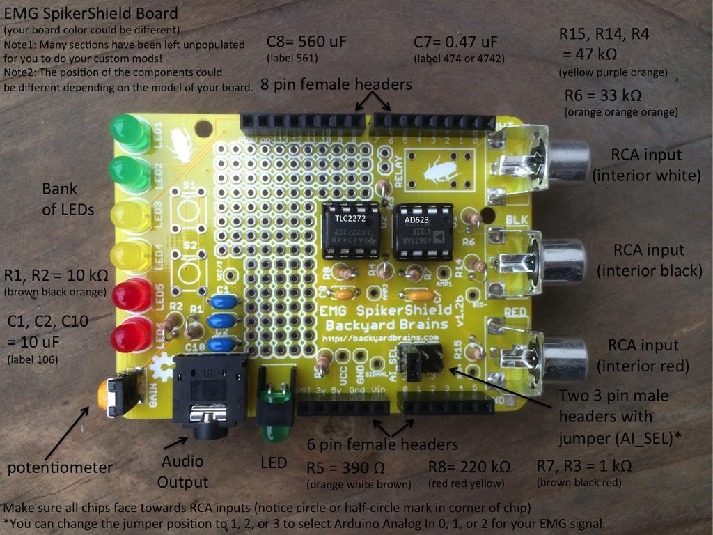
1 EMG SpikerShield v1.2 Instructions Prepare yourself. In 2-4 hours, you will have built your own Arduino compatible EMG SpikerBox, so you can control robots and anything you wish with your EMG muscle activity. Materials Needed: 1. An EMG SpikerShield Bag of Parts 2. Soldering Iron 3. Solder 4. Magnifying Glass to read labels on Chips and Capacitors 6. Silly Putty to hold components in place on board while you solder on backside 8. Wire Strippers and Wire Clippers A Soldering Iron can be purchased at RadioShack or any local hardware store. The Magnifying Glass and Silly Putty are available at drug stores. EMG SpikerShield Circuit Construction (refer to photograph on page 4 while building): 1. Install RCA inputs, and note red, black, and white labels on board that refer to red, black, and white RCA inputs (the inside of the RCA input is colored). 2. Install Audio Out Connector. You may find Silly Putty helps keep the connector in place when you solder it to the board. 3. Install LED (Light- Emitting Diode green) 4. Install the two chip holders (align the half- circle on side of the chip holder with the half circle on the board) 5. Install potentiometer 6. Install the two 3- pin headers over AI_select and place jumper over either 1, 2, or 3 (we use 1 as default which refers to Analog In 0 on Arduino). You can move the jumper to 1 (Arduino Analog In 1) or 2 (Arduino Analog In 2) depending on your preference and which Analog In on the Arduino you want you EMG signal to feed through. 7. Install 10 uf Capacitors at C1, C2, and C10 (blue ones they have 106 labels on them) 8. Install 0.47 uf Capacitor at C7 (this has 474 or 4742 label on it) 9. Install 560 pf Capacitor at C8 (561 label) 10. Install 47kΩ Resistors at R15, R14, and R4 (yellow purple orange) 11. Install 10kΩ Resistors at R1 and R2 (brown black orange) 12. Install 1kΩ Resistor at R7 and R3 (brown black red) 13. Install 390Ω Resistor at R5 (orange white brown) 14. Install 33kΩ Resistor at R6 (orange orange orange) 15. Install 220kΩ Resistor at R8 (red red yellow) 16. Install 8 pin female header in Digital I/O bank Install 8 pin female header in Digital I/O bank 9 Aref 18. Install 5 pin female header in Analog In bank Install 5 pin female header in bank Vin RST


2 20. Install the 6 LEDs along the edge of the board. The longer leg goes in the hole closest to the edge of the board. 21. Install chips in chip holders, with circle mark on chip towards the RCA input. AD623 chip goes in U1, and TLC2272 chip goes in U2 22. Add a strip of electrical tape over the LED contacts to avoid a potential shortcircuit when the with the Arduino Board And your board is ready! It is now time to build the electrode cables.


3 Build Electrode Cables 1- Split your three speaker wires pairs so you end up with six ~3 foot lengths of wire. You will only use three of these lengths that s OK 2. Unscrew RCA input jackets, strip about ¼ inch of a length of your speaker wire, and solder to the center section of the RCA connector. Do this for all three RCA input connectors. 3. Crimp tap, and screw RCA jackets back on 4. Solder alligator clips (red RCA to red alligator, black RCA to black alligator, white RCA to bare metal alligator) to the other ends of the wires. For the red and black alligator clips, remove one grip, slide grip over wire, solder wire to clip, and slip grip back on. For the bare metal alligator clip, you can often get away with simply fastening wire underneath the screw on the bare metal alligator clip in lieu of soldering it.


4 Final Assembly 1. Stack your EMG SpikerShield on top of your Arduino Uno. You can buy an Arduino Uno from RadioShack, SparkFun, Make, etc. Note that the EMG SpikerShield does not fill every single header on the Arduino. 2. Plug in your electrode cables, and you are done! To keep the electrode cables from getting tangled, you may find twistie ties around the cables placed every ~8 inches helps. Note that the Arduino needs to be plugged into a USB Power Source to Operate. Go to the experiments page on our backyardbrains.com website to learn how to use your new tool for creativity!
5
Uno Compatible Pogobed Kit
 Uno Compatible Pogobed Kit Intermediate Level The pogobed kit is a hardware fixture that enables you to temporarily connect from your Arduino development board to any Arduino shield. Using the springloaded
ARDUINO 2WD SMART ROBOT CAR KIT
 EN ARDUINO 2WD SMART ROBOT CAR KIT P a g e 2 PARTS LIST Please make sure that the following pieces are included in your kit Component Quantity Remarks Arduino Sensor Shield v5.0 1 Align pins using needle
CLASSIC PEDAL KIT. Assembly Instructions WHEN YOU CAN T BUY IT BUILD IT. StewMac Monarch RARE / VINTAGE / HARD TO GET
 Sheet #i-2205 Updated 2/8 StewMac Monarch CLASSIC PEDAL KIT Kit case is unpainted IN COLLABORATION WITH EarthQuakerDevices Assembly Instructions The Monarch Overdrive is an all discrete, FET-based dirt
Soldering Pi2Go Lite. Soldering the Line-Follower PCB
 Soldering Pi2Go Lite First check which version of the main PCB you have. It is marked above the left motor "Pi2Go-Lite v1.x". There are minor changes to some parts of the build. v1.0 (initial release)
DIY Synth Kit - Manual STUTTER SYNTH
 DIY Synth Kit - Manual STUTTER SYNTH Welcome to the DIY Synth - Manual This is a step-by-step guide to making your own electronic Synth. All you will need is your hands and your DIY Synth kit which includes
Build Instructions and User Guide
 Build Instructions and User Guide Getting Started To build the Rock Drill 4069 you will need: Solder Wire Cutters Soldering Iron Small pliers The kit is suitable for beginners or more experienced builders
DIY Synth Kit - Manual
 DIY Synth Kit - Manual Welcome to the DIY Synth - Manual This is a step-by-step guide to making your own electronic Synth. All the equipment you ll need to make your synth is your DIY Synth kit and of
MOTHMAN FUZZ ASSEMBLY INSTRUCTIONS RECOMMENDED TOOL AND SUPPLY LIST MOTHMAN FUZZ KIT PARTS LIST
 MOTHMAN FUZZ ASSEMBLY INSTRUCTIONS Thank you for purchasing the J201 Clean Boost Pedal Kit from Mammoth Electronics! This is a intermediate level kit that and we have made every effort to make the assembly
STAY ON TRACK WITH THIS LINE FOLLOW BUGGY WITH :MOVE LINE FOLLOW BOARD FOR BBC MICRO:BIT
 STAY ON TRACK WITH THIS LINE FOLLOW BUGGY WITH :MOVE LINE FOLLOW BOARD FOR BBC MICRO:BIT BUILD INSTRUCTIONS LIST OF FIXINGS M3 BOLTS M3 NUTS STANDOFFS 6mm x12 x4 x4 10mm x4 x12 12mm x2 30mm x2 20mm M-F
These instructions show how to build the Remote Controlled Fart machine Sound Kit.
 Remote Controlled Fart Machine Assembly Instructions These instructions show how to build the Remote Controlled Fart machine Sound Kit. Tools Required Drill with 7/64, 3/16, and ¼ drill bits. Holt melt
TIMER PROJECT KIT ESSENTIAL INFORMATION. Version 2.0 TIME SOMETHING WITH THIS
 ESSENTIAL INFORMATION BUILD INSTRUCTIONS CHECKING YOUR PCB & FAULT-FINDING MECHANICAL DETAILS HOW THE KIT WORKS TIME SOMETHING WITH THIS TIMER PROJECT KIT Version 2.0 Build Instructions Before you start,
White Light CLASSIC PEDAL KIT. Assembly Instructions WHEN YOU CAN T BUY IT BUILD IT. StewMac RARE / VINTAGE / HARD TO GET
 Sheet #i-2206 Updated 5/18 StewMac White Light CLASSIC PEDAL KIT Kit case is unpainted IN COLLABORATION WITH EarthQuakerDevices Assembly Instructions The White Light Overdrive is based on vintage overdrives
Lab 4.4 Arduino Microcontroller, Resistors, and Simple Circuits
 Lab 4.4 Arduino Microcontroller, Resistors, and Simple Circuits A microcontroller is a "brain" of a mechatronic system that interfaces sensors with a computer. Microcontrollers can perform math operations,
WIRING THE HEATER POWER SUPPLY
 WIRING THE HEATER POWER SUPPLY Fig. 14 13/14 Take the longer PS board (with the 47R resistors and the fuse) and, using M3x6 screws, fix it to the chassis to the left of the mains transformer. The diodes
DECIDUOUS FILTER ASSEMBLY INSTRUCTIONS RECOMMENDED TOOL AND SUPPLY LIST DECIDUOUS FILTER KIT PARTS LIST
 DECIDUOUS FILTER ASSEMBLY INSTRUCTIONS Thank you for purchasing the Deciduous Filter Effect Pedal Kit from Mammoth Electronics! This is an intermediate level kit and we have made every effort to make the
VEX Extra Parts List. SOLDERING Vice Soldering Iron Wire Strippers Black and Red Wire Touch Sensor Solder Safety Glasses.
 The Carnegie Mellon VEX curriculum contains an instructional link called Resources. This section includes many additional learning resources that a teacher can use to teach electronics, mechanics, basic
ASSEMBLY INSTRUCTIONS FOR NEW FK109 4 LED Railroad Crossing Flasher Kit WITH ADJUSTABLE FLASHING SPEED CONTROL with 4 Red 3mm Leds
 ASSEMBLY INSTRUCTIONS FOR NEW FK109 4 LED Railroad Crossing Flasher Kit WITH ADJUSTABLE FLASHING SPEED CONTROL with 4 Red 3mm Leds Description: Very easy to build, The FK109 Led Flasher kit makes the perfect
Assembly Manual for ISDR-136-KIT
 Assembly Manual for ISDR-136-KIT ICAS Enterprises Last Updated March 21 st, 2012 This SDR receiver kit is intended for the 136kHz band. The kit utilizes DIP IC components (no SMD) so that even a beginner
IV-3 VFD Shield for Arduino. Assembly Manual
 June 2014 Table of Contents 1 Overview Features Applications 3 3 3 2 Assembly Hints 4 3 PCB Overview 5 4 Circuit Diagram 6 5 Assembly Diodes and IC socket Electrolytic capacitors Ceramic capacitors 10K
Quiz Buzzer. Build Instructions. Issue 1.2
 Build Instructions Issue 1.2 Build Instructions Before you put any components in the board or pick up the soldering iron, just take a look at the Printed Circuit Board (PCB). The components go in the side
750 Paso Wiring Upgrade
 750 Paso Wiring Upgrade Supplies required: 2 Bosch 30A/12V Relays # #0 332 209 150 (with mounting tab) 1 30 Amp fuse holder 1 10 Amp fuse holder 12 inches of brown 12 gauge wire 60 inches of red 14 gauge
QRPGuys Digital RF Probe
 QRPGuys Digital RF Probe First, familiarize yourself with the parts and check for all the components. If a part is missing, please contact us and we will send one. This kit contains seventeen 1206 size
Bachmann Digital Sound Decoder Installation Notes
 New Dimensions in Digital Sound Technology TM APPLICATION NOTE Bachmann 2-6-6-2 Digital Sound Decoder Installation Notes Overview This application note describes the installation of a DSD-090LC Digital
ALARM KIT ESSENTIAL INFORMATION. Version 2.0 WHAT CAN YOU PROTECT WITH THIS
 ESSENTIAL INFORMATION BUILD INSTRUCTIONS CHECKING YOUR PCB & FAULT-FINDING MECHANICAL DETAILS HOW THE KIT WORKS WHAT CAN YOU PROTECT WITH THIS ALARM KIT Version 2.0 Build Instructions Before you start,
Installation Tips Crimestopper/ProStart Remote Start system + PLJX + DLRM + SPDT (for GM vehicles) T0760 v1.1 updated 2/5/14
 T0760 v1.1 updated 2/5/14") Installation Tips Crimestopper/ProStart Remote Start system + PLJX + DLRM + SPDT (for GM vehicles) T0760 v1.1 updated 2/5/14 Thank you for purchasing your remote start from MyPushcart.com - an industry
Installation Tips Crimestopper/ProStart Remote Start system + PLJX + DLRM + SPDT (for GM vehicles) T0760 v1.1 updated 2/5/14 Thank you for purchasing your remote start from MyPushcart.com - an industry
TIMED NIGHT LIGHT KIT
 ESSENTIAL INFORMATION BUILD INSTRUCTIONS CHECKING YOUR PCB & FAULT-FINDING MECHANICAL DETAILS HOW THE KIT WORKS RELAX YOUR WAY TO SLEEP WITH THIS TIMED NIGHT LIGHT KIT Version 2.0 Build Instructions Before
SB-GVS Shield v1.0. ! Ideal for servo & sensor accessories (Phidgets, Seeed Bricks)! Full break-out for all 12 digital lines & 6 analog lines 2
! Full break-out for all 12 digital lines & 6 analog lines 2") SB-GVS Shield v1.0 Arduino tm -Compatible Sensor Interface Connect up 18 peripherals to the popular Ground/Voltage/Signal interface. Got more? Use the IC-interface too! Build Time: 0mins Skill Level: Beginner
SB-GVS Shield v1.0 Arduino tm -Compatible Sensor Interface Connect up 18 peripherals to the popular Ground/Voltage/Signal interface. Got more? Use the IC-interface too! Build Time: 0mins Skill Level: Beginner
JHS 808. CLASSIC PEDAL KIT Assembly Instructions. StewMac
 heet #i-2150 Updated 12/17 tewmac JH 808 CLAIC PEDAL KI Assembly Instructions he JH808 is one of the great stompboxes from JH, makers of high-end effects pedals. Whenever JH adds a new pedal to their line,
Handyman Motor Capacitor Meter PART NO
 Handyman Motor Capacitor Meter PART NO. 2225174 To test a motor-run capacitor in the field with no capacitance meter at hand, you had to hook up the capacitor through an extension cable to a 120V wall
Prusa i3 Printer Assembly Guide
 Prusa i3 Printer Assembly Guide Special thanks to Carlos Sanchez and Miguel Sanchez for the graphics. All graphics captured from their great animation: http://www.carlos-sanchez.com/ Prusa3/ For copyright
General Purpose Flasher Circuit
 General Purpose Flasher Circuit By David King Background Flashing lights can be found in many locations in our neighbourhoods, from the flashing red light over a stop sign, a yellow warning light located
IDC-136II-KIT 136kHz DC RX Assembly Guide
 IDC-136II-KIT 136kHz DC RX Assembly Guide ICAS Enterprises May 2 nd,2016 The IDC-136II-KIT is a 136kHz direct conversion receiver. Most of the SDR software can be used with this receiver. It is quite easy
Read the entire installation manual. There are several safety tips there that you need to know before you start
 Installation Tips for RS4 + INTSL (2) TIP SHEET T0749 Buick Century: 2000-2005 Buick LeSabre: 2000-2005 Buick Park Avenue: 1999-2005 Buick Ranier: 2004-2007 Cadillac Escalade: 2003-2007 Chevrolet Avalanche:
Nissan Pathfinder (without NAV) (with color screen) HG
 (with color screen) HG") Installation instructions for part 99-7627HG Nissan Pathfinder 2013-2016 (without NAV) (with color screen) 99-7627HG KIT FEATURES ISO DIN radio provision with pocket ISO DDIN radio provision Painted to
Installation instructions for part 99-7627HG Nissan Pathfinder 2013-2016 (without NAV) (with color screen) 99-7627HG KIT FEATURES ISO DIN radio provision with pocket ISO DDIN radio provision Painted to
Application Note. Walthers/Proto 2000 E7A Tsunami Digital Sound Decoder Installation Notes
 Application Note Overview This application note describes how to install a TSU-1000 digital sound decoder into a Walthers/ Proto 2000 E7A. Skill Level 2: The entire installation can be completed in one
Wiring the FRC Control System
 Wiring the FRC Control System This document details the wiring of a basic electronics board for bench-top testing. Some images shown in this section reflect the setup for a Robot Control System using Spark
Installation Tips - (Crimestopper RS1/RS2) & (Fortin EVO-ALL 5): *regular key & automatic transmission only*
 & (Fortin EVO-ALL 5): *regular key & automatic transmission only*") Installation Tips - (Crimestopper RS1/RS2) & (Fortin EVO-ALL 5): TIP SHEET T3385f, T3413f *regular key & automatic transmission only* Thank you for purchasing your remote start from MyPushcart.com - an
Installation Tips - (Crimestopper RS1/RS2) & (Fortin EVO-ALL 5): TIP SHEET T3385f, T3413f *regular key & automatic transmission only* Thank you for purchasing your remote start from MyPushcart.com - an
Assembly Manual for New Control Board 22 June 2018
 Assembly Manual for New Control Board 22 June 2018 Parts list Arduino 1 Arduino Pre-programmed 1 Faceplate Assorted Header Pins Full Board Rev A 9 104 capacitors 1 Rotary encode with switch 1 5-volt regulator
KORG KR-55. µsync installation guide version 1.0, 14 October
 KORG KR-55 µsync installation guide version 1.0, 14 October 2016 www.artefacts.nl Introduction The Korg KR-55 or KR-55b has no standard din sync input. Artefacts developed a piece of hardware to convert
Mableaudio Company limited
 Mableaudio Company limited Web: www.mableaudio.com [5E3 assembly manual] Tel:0086-755-83996326 fax:0086-755-83996326 Contact: Ms Mable mable@mableaudio.com WARNING! This amp operates at voltages that may
THE WAHTZ WAH (K-985)
") THE WAHTZ WAH (K-985) Output Jack Unplug from the Wahtz input jack (other side) when not in use to save battery life. 9 VDC CENTER (-) ADAPTER Use these instructions to learn: How to build a wah-wah pedal
THE WAHTZ WAH (K-985) Output Jack Unplug from the Wahtz input jack (other side) when not in use to save battery life. 9 VDC CENTER (-) ADAPTER Use these instructions to learn: How to build a wah-wah pedal
CTB-16K Hobbyist Line Kit 40 Amp 16 Channel Light Controller Assembly Manual *** Preliminary ***
 CTB-16K Hobbyist Line Kit 40 Amp 16 Channel Light Controller Assembly Manual *** Preliminary *** Version 1.0 January 12, 2006 Copyright Light O Rama, Inc. 2006 Table of Contents 1 Introduction... 3 2 Required
MONGOOSE. Introduction. < blueroomelectronics > Assembly Instructions. Mongoose was designed as an introduction to Mechatronics.
 MONGOOSE Assembly Instructions Introduction Mongoose was designed as an introduction to Mechatronics Page 1 of 12 Before you start The Mongoose is a complex kit and skipping instructions is not advised,
Connecting the rear fog light on the A4 Jetta, while keeping the 5 Light Mod
 Connecting the rear fog light on the A4 Jetta, while keeping the 5 Light Mod DISCLAIMER: I'm human and make mistakes. If you spot one in this how to, tell me and I'll fix it This was done on my 99.5 Jetta.
Contents. TCS/ Driver Mod Installation Manual
 Contents Introduction... 1 TCS Packing List... 3 Tools Needed for Installation... 4 How to Properly Solder... 5 Soldering Standard Butt Connection... 5 Soldering T Connection... 6 How to Properly Crimp...
ALL AMERICAN. CLASSIC PEDAL KIT Assembly Instructions. StewMac
 heet #i-2153 Updated 12/17 tewmac ALL AMERICAN CLAIC PEDAL KI Assembly Instructions he ALL-AMERICAN is one of the great stompboxes from JH, makers of high-end effects pedals. Whenever JH adds a new pedal
(2 DPDT 2 4 X
 Dynaco ST-120 with VTA driver board Kit instruction manual Triode/Pentode version Congratulations on your purchase of the Dynaco ST-120 with VTA driver board kit. Every effort has been made to give you
SM361 RIG SWITCH CONSTRUCTION MANUAL
 SM361 RIG SWITCH CONSTRUCTION MANUAL Document ver 1, For software release ver 1.1 May 27, 2016 Controls the power of 12V equipment while a vehicle is in use Product Development by: SM361 RIG SWITCH OVERVIEW
PLEASE READ ALL DIRECTIONS BEFORE STARTING INSTALLATION
 PARTS LIST 2009-2013 Honda Goldwing Installation Instructions 1 Power Commander 2 USB Cables 1 CD-ROM 1 Installation Guide 2 Power Commander Decals 2 Dynojet Decals 4 Velcro strips 1 Alcohol swab 2 O2
Chapter 2. Battery Charger and Base Assembly
 Chapter 2 Battery Charger and Base Assembly 11 CHAPTER 2. BATTERY CHARGER AND BASE ASSEMBLY 2.1 Section Overview This Lab teaches students how to assemble a Tekbot, in the following steps: Describe the
Installation Tips for your Crimestopper/ProStart Remote Start system (add-on for GM vehicles) v1.02 updated 1/16/2013
 v1.02 updated 1/16/2013") Installation Tips for your Crimestopper/ProStart Remote Start system (add-on for GM vehicles) v1.02 updated 1/16/2013 Thank you for purchasing your remote start from MyPushcart.com - an industry leader
Installation Tips for your Crimestopper/ProStart Remote Start system (add-on for GM vehicles) v1.02 updated 1/16/2013 Thank you for purchasing your remote start from MyPushcart.com - an industry leader
Wiring the 2015 FRC Control System
 Wiring the 2015 FRC Control System This document details the wiring of a basic electronics board for bench-top testing. The images shown in this section reflect the setup for a Robot Control System using
Disaster Transport CLASSIC PEDAL KIT. Assembly Instructions WHEN YOU CAN T BUY IT BUILD IT. StewMac RARE / VINTAGE / HARD TO GET
 StewMac Sheet #i-2203 Updated 5/8 Disaster Transport CLASSIC PEDAL KIT Kit case is unpainted IN COLLABORATION WITH EarthQuakerDevices Assembly Instructions The Disaster Transport is an analog voiced digital
Installation Tips for your RS-1 + Honda-SL3 (1.b) Remote starter Honda: ( FIT), ( Pilot), ( Ridgeline) Acura: ( MDX)
 Remote starter Honda: ( FIT), ( Pilot), ( Ridgeline) Acura: ( MDX)") Installation Tips for your RS-1 + Honda-SL3 (1.b) Remote starter Honda: ( 06-08 FIT), ( 05-08 Pilot), ( 06-13 Ridgeline) Acura: ( 03-06 MDX) TIP SHEET T0777 Thank you for purchasing your remote start from
Installation Tips for your RS-1 + Honda-SL3 (1.b) Remote starter Honda: ( 06-08 FIT), ( 05-08 Pilot), ( 06-13 Ridgeline) Acura: ( 03-06 MDX) TIP SHEET T0777 Thank you for purchasing your remote start from
Installation Tips for your Add-on Remote Start (for GM vehicles with INTSL Install 2) v3.2 Updated 11/12/2012
 v3.2 Updated 11/12/2012") Installation Tips for your Add-on Remote Start (for GM vehicles with INTSL Install 2) v3.2 Updated 11/12/2012 Thank you for purchasing your remote start from MyPushcart.com - an industry leader in providing
Installation Tips for your Add-on Remote Start (for GM vehicles with INTSL Install 2) v3.2 Updated 11/12/2012 Thank you for purchasing your remote start from MyPushcart.com - an industry leader in providing
BATTERY BOOSTER SHIELD
 BATTERY BOOSTER SHIELD Introduction The Battery Booster Shield is an add-on for the Arduino that efficiently boosts a lower input voltage (0.65V to 4.5V) up to 5V. It powers the Arduino and peripherals
TIP SHEET T2352, T3396. Installation Tips for RS1 + EVO-ALL 1-BUTTON REMOTE STARTER FOR: Acura RDX PUSH-TO-START / AUTOMATIC
 Installation Tips for RS1 + EVO-ALL 1-BUTTON REMOTE STARTER FOR: Acura RDX 2013-2015 PUSH-TO-START / AUTOMATIC TIP SHEET T2352, T3396 Thank you for purchasing your remote start from MyPushcart.com - an
MOD 102+ GUITAR AMP KIT (K-MOD102+)
") MOD 102+ GUITAR AMP KIT (K-MOD102+) ON BASS 4 6 TREBLE 4 6 VOLUME 4 6 7 7 7 STBY OFF STBY 2 8 MOD 102+ TUBE AMP KIT 1 9 modkitsdiy.com 0 10 Pull-MID BOOST 2 8 1 9 0 10 Pull-BRIGHT 2 8 1 9 0 10 Pull-TURBO
MOD 102+ GUITAR AMP KIT (K-MOD102+) ON BASS 4 6 TREBLE 4 6 VOLUME 4 6 7 7 7 STBY OFF STBY 2 8 MOD 102+ TUBE AMP KIT 1 9 modkitsdiy.com 0 10 Pull-MID BOOST 2 8 1 9 0 10 Pull-BRIGHT 2 8 1 9 0 10 Pull-TURBO
DARK ACTIVATED COLOUR CHANGING NIGHT LIGHT KIT
 ESSENTIAL INFORMATION BUILD INSTRUCTIONS CHECKING YOUR PCB & FAULT-FINDING MECHANICAL DETAILS HOW THE KIT WORKS CREATE SOOTHING LIGHTING EFFECTS WITH THIS DARK ACTIVATED COLOUR CHANGING NIGHT LIGHT KIT
Installation Tips for your Crimestopper/ProStart Remote Start system (for GM vehicles) v1.01 updated 2/27/2012
 v1.01 updated 2/27/2012") Installation Tips for your Crimestopper/ProStart Remote Start system (for GM vehicles) v1.01 updated 2/27/2012 Thank you for purchasing your remote start from MyPushcart.com - an industry leader in providing
Installation Tips for your Crimestopper/ProStart Remote Start system (for GM vehicles) v1.01 updated 2/27/2012 Thank you for purchasing your remote start from MyPushcart.com - an industry leader in providing
MOD 102 GUITAR AMP KIT (K-MOD102)
") MOD 0 GUITAR AMP KIT (K-MOD0) ON BASS TREBLE VOLUME MOD 0 TUBE AMP KIT 0 0 0 0 0 0 OFF Use these instructions to learn: How to build a tube amp. This tube guitar amplifier circuit is based on a classic
MOD 0 GUITAR AMP KIT (K-MOD0) ON BASS TREBLE VOLUME MOD 0 TUBE AMP KIT 0 0 0 0 0 0 OFF Use these instructions to learn: How to build a tube amp. This tube guitar amplifier circuit is based on a classic
SUPER CAPACITOR CHARGE CONTROLLER KIT
 TEACHING RESOURCES ABOUT THE CIRCUIT COMPONENT FACTSHEETS HOW TO SOLDER GUIDE POWER YOUR PROJECT WITH THIS SUPER CAPACITOR CHARGE CONTROLLER KIT Version 2.0 Teaching Resources Index of Sheets TEACHING
Installation Tips for RS1 + EVO-RIDE + SPDT. *(reglar key, automatic transmission vehicles ONLY)*
*") Installation Tips for RS1 + EVO-RIDE + SPDT TIP SHEET T1235 *(reglar key, automatic transmission vehicles ONLY)* Thank you for purchasing your remote start from MyPushcart.com - an industry leader in providing
Installation Tips for RS1 + EVO-RIDE + SPDT TIP SHEET T1235 *(reglar key, automatic transmission vehicles ONLY)* Thank you for purchasing your remote start from MyPushcart.com - an industry leader in providing
BMW S1000RR Z-Fi QS / Z-Fi TC Installation Instructions P/N S541S, S541R, T541S, T541R
 2009-2013 BMW S1000RR Z-Fi QS / Z-Fi TC Installation Instructions P/N S541S, S541R, T541S, T541R WARNING! USE ONLY IN RACE OR OTHER CLOSED COURSE APPLICATIONS AND NEVER ON PUBLIC ROADS Z-Fi products do
22K (red red orange gold) 1pcs. 33K (orange orange orange gold) 5pc. 2.7 M (green violet red gold) 2pc.
 1pcs. 33K (orange orange orange gold) 5pc. 2.7 M (green violet red gold) 2pc.") TURNING FROG Long pliers, soldering, soldering iron stand with sponge, 2 AA batteries, one 9V battery, Tin, diagonal cutting pliers Turning Frog is a robot that uses a microphone as a detector. When microphone
TURNING FROG Long pliers, soldering, soldering iron stand with sponge, 2 AA batteries, one 9V battery, Tin, diagonal cutting pliers Turning Frog is a robot that uses a microphone as a detector. When microphone
Installation Tips for your Remote Start system (for RS4LX>GMBP for GM vehicles)
") Installation Tips for your Remote Start system (for RS4LX>GMBP for GM vehicles) Thank you for purchasing your remote start from MyPushcart.com - an industry leader in providing remote starts to doit-yourself
Installation Tips for your Remote Start system (for RS4LX>GMBP for GM vehicles) Thank you for purchasing your remote start from MyPushcart.com - an industry leader in providing remote starts to doit-yourself
GMOS-LAN-034 GM LAN-11 OnStar interface
 Installation instructions for GMOS-LAN-034 GMOS-LAN-034 GM LAN-11 OnStar interface 2006-2012 Provides accessory power (12-volt 10-amp) Retains R.A.P. (retained accessory power) Can be used in non-amplified,
CCL LLC 88 Black Falcon Ave., Ste. 247, Boston, MA USA Contact: Antea Risso
 88 Black Falcon Ave., Ste. 247, Boston, MA 02210 USA Contact: Antea Risso Digi-Key Corporation e-mail: antea@arduino.org 701 Brooks Ave.South PRODUCT CHANGE NOTIFICATION Thief River Falls, MN 5670 January
Assembly Instructions for the KA Electronics Flat MM Phono Preamplifier
 Assembly Instructions for the KA Electronics Flat MM Phono Preamplifier Install IC sockets Flat MM Phono Preamp PC Board Stuffing Guide Place the PC Board on the bench silkscreen side face up. Drop six
Installation Tips for RS4/RS7 + EVO-ALL (NIS 3.c) + 2 diodes
 + 2 diodes") Installation Tips for RS4/RS7 + EVO-ALL (NIS 3.c) + 2 diodes TIP SHEET T3093 + T3103 FOR: NISSAN ( 09-14 Cube), ( 11-14 Juke), & ( 07-11 Versa) automatic, regular key vehicles Thank you for purchasing
Installation Tips for RS4/RS7 + EVO-ALL (NIS 3.c) + 2 diodes TIP SHEET T3093 + T3103 FOR: NISSAN ( 09-14 Cube), ( 11-14 Juke), & ( 07-11 Versa) automatic, regular key vehicles Thank you for purchasing
ADDING A SUBWOOFER TO A BOSE EQUIPTED MK2 AUDI TT COUPE
 ADDING A SUBWOOFER TO A BOSE EQUIPTED MK2 AUDI TT COUPE Mark Davis March 2008 Obligatory Disclaimer This document remains the copyright of Mark Davis. No unauthorised distribution or sale of this document,
SCA-80(Q) C11 REPLACEMENT ASSEMBLY MANUAL
 C11 REPLACEMENT ASSEMBLY MANUAL") SCA-80(Q) C11 REPLACEMENT ASSEMBLY MANUAL 2014-2016 AkitikA, LLC All rights reserved Revision 1p05 July 3, 2016 Page 1 of 15 Table of Contents Table of Contents... 2 Table of Figures... 2 Section 1: About
SCA-80(Q) C11 REPLACEMENT ASSEMBLY MANUAL 2014-2016 AkitikA, LLC All rights reserved Revision 1p05 July 3, 2016 Page 1 of 15 Table of Contents Table of Contents... 2 Table of Figures... 2 Section 1: About
Installation Tips for your Remote Start/Keyless Entry (for Mazda Vehicles) v3.1 Updated 9/22/2012
 v3.1 Updated 9/22/2012") Installation Tips for your Remote Start/Keyless Entry (for Mazda Vehicles) v3.1 Updated 9/22/2012 Thank you for purchasing your remote start from MyPushcart.com - an industry leader in providing remote
Installation Tips for your Remote Start/Keyless Entry (for Mazda Vehicles) v3.1 Updated 9/22/2012 Thank you for purchasing your remote start from MyPushcart.com - an industry leader in providing remote
Installation Instructions for the Plug & Play Remote Start Package (EVOCHR4)
") T6002 v1.1 02/2013 Installation Instructions for the Plug & Play Remote Start Package (EVOCHR4) For CHRYSLER Town & Country 2008-2012 Review the remote start installation manual for safety instructions!
T6002 v1.1 02/2013 Installation Instructions for the Plug & Play Remote Start Package (EVOCHR4) For CHRYSLER Town & Country 2008-2012 Review the remote start installation manual for safety instructions!
Installation Instructions for the Plug & Play Chrysler/Dodge/Jeep Remote Start Package w/mux T5
 v1.01 12/14/2102 Installation Instructions for the Plug & Play Chrysler/Dodge/Jeep Remote Start Package w/mux T5 Review the remote start installation manual for safety instructions! Overview Your kit consists
Circuit Basics and Components
 Circuit Basics Electric circuits are arrangements of conductors and components that permit electrical current to flow. A circuit can be as simple as a battery and lamp or as sophisticated as a computer.
Installation Instructions for the Plug & Play Remote Start Package (EVOCHR5)
") T6018 v1.1 02/2013 Installation Instructions for the Plug & Play Remote Start Package (EVOCHR5) For DODGE Nitro 2007-2011 Review the remote start installation manual for safety instructions! Overview Your
T6018 v1.1 02/2013 Installation Instructions for the Plug & Play Remote Start Package (EVOCHR5) For DODGE Nitro 2007-2011 Review the remote start installation manual for safety instructions! Overview Your
Step 1 Wiring your remote start. Installation Tips for your Remote Start system (for GM vehicles) V3.3 revised 9/12/2013
 V3.3 revised 9/12/2013") Installation Tips for your Remote Start system (for GM vehicles) V3.3 revised 9/12/2013 Thank you for purchasing your remote start from MyPushcart.com - an industry leader in providing remote starts to
Installation Tips for your Remote Start system (for GM vehicles) V3.3 revised 9/12/2013 Thank you for purchasing your remote start from MyPushcart.com - an industry leader in providing remote starts to
Schematic VCC J1 1 CON1 +5V D26 D25 D7 D8 D9 D10 D11 D12 D19 D20 D21 D22 D23 D24 D1 D2 D3 D4 D5 D6 D13 D14 D15 D16 D17 D18 R4 100R R2 100R R6 100R
 Schematic +5V S D1 D2 D3 D4 D5 D6 D7 D8 D9 D10 D11 D12 D19 D20 D21 D22 D23 D24 D13 D14 D15 D16 D17 D18 D25 D26 R1 4K7 R2 100R Q1 9014-PNP C1 47uF R3 4K7 R4 100R Q2 9014-PNP C2 47uF R5 4K7 R6 100R Q3 9014-PNP
NOTE: CAPACITOR LEADS IN FIG #1 MAY REQUIRE SPLICING USING GA BUSS WIRE & SLEEVING AS NECESSARY TO ATTAIN REQUIRED LEAD LENGTH. 704
 DIGITAL READ OUT (2.70 IDEAL FOR THIS RESISTOR) ENGAGE DCVΩ BUTTON DIGITAL VOLT METER ZERO ADJUST-CONNECT (2) ALLIGATOR CLIPS TOGETHER & ADJUST UNTIL DIGITAL READ OUT IS 0.00 NOTE: THIS MUST BE REPEATED
CHAPTER 2. Current and Voltage
 CHAPTER 2 Current and Voltage The primary objective of this laboratory exercise is to familiarize the reader with two common laboratory instruments that will be used throughout the rest of this text. In
B. Ford Fusion 2013-up
 99-5841B INSTALLATION INSTRUCTIONS Ford Fusion 2013-up KIT FEATURES ISO DIN radio provision with pocket ISO DDIN radio provision Integrated controls for info center Painted black Note: Does not support
CHEVY NOVA w/reverse Four Panel Sequential LED Taillight Kit Installation Guide
 1970-72 CHEVY NOVA w/reverse Four Panel Sequential LED Taillight Kit Installation Guide Kit Contents: 4 LED panels 4 rubber grommets 1 power wire with t-tap 1 driver side LED harness, 24 (5 pin) 1 passenger
MOTOALLIANCE WINCH MOUNT
 , / 1-866-527-7637 www.motoalliance.com MOTOALLIANCE WINCH MOUNT Polaris RZR Thank you for purchasing our MotoAlliance winch mount(s). You now own a premium custom winch mount to allow you to use your
AX-LR903. Land Rover Range Rover Evoque (with M.O.S.T. 25 amplifier) Data Interface with SWC & Factory Display Retention
 Data Interface with SWC & Factory Display Retention") AX-LR903 INSTALLATION INSTRUCTIONS Land Rover Range Rover Evoque (with M.O.S.T. 25 amplifier) Data Interface with SWC & Factory Display Retention 2012-2014 INTERFACE FEATURES Provides accessory power Retains
AX-LR903 INSTALLATION INSTRUCTIONS Land Rover Range Rover Evoque (with M.O.S.T. 25 amplifier) Data Interface with SWC & Factory Display Retention 2012-2014 INTERFACE FEATURES Provides accessory power Retains
OLDSMOBILE CUTLASS
 1971-72 OLDSMOBILE CUTLASS Four Panel Sequential LED Tail Light Kit Installation Guide Kit Contents: 4 LED panels 1 Connector/Wire Kit 1 Grommet/Boot Kit 1 Power wire 2 Pigtail Harness Kits 1 Crimp terminal
RS4 / RS7 + (4) + SPDT
 + SPDT") TIP SHEET Installation Tips for RS4 / RS7 + Honda-SL3 (4) + SPDT + Diode x2 T0776, T0731 Honda: ( 08-12 Accord), ( 12-13 Civic), 12-13 CRV), ( 11-13 Odyssey), ( 09-13 Pilot) Acura: ( 09-13 TSX) Thank you
TIP SHEET Installation Tips for RS4 / RS7 + Honda-SL3 (4) + SPDT + Diode x2 T0776, T0731 Honda: ( 08-12 Accord), ( 12-13 Civic), 12-13 CRV), ( 11-13 Odyssey), ( 09-13 Pilot) Acura: ( 09-13 TSX) Thank you
BehringerMods.com. Instructions for modification of Behringer DCX analog inputs and outputs
 BehringerMods.com Instructions for modification of Behringer DCX analog inputs and outputs The following instructions will cover the details of fully modifying a unit with analog output and analog input
Arlo Power Distribution Board Kit Rev B (#28996)
") Web Site: www.parallax.com Forums: forums.parallax.com Sales: sales@parallax.com Technical: support@parallax.com Office: (916) 624-8333 Fax: (916) 624-8003 Sales: (888) 512-1024 Tech Support: (888) 997-8267
Web Site: www.parallax.com Forums: forums.parallax.com Sales: sales@parallax.com Technical: support@parallax.com Office: (916) 624-8333 Fax: (916) 624-8003 Sales: (888) 512-1024 Tech Support: (888) 997-8267
k" or #8 nut driver A pair of regular pliers can substitute for the nut drivers but will
 Page of 3 ARIES SYSTEM 300 MUSIC SYNTHESIZER Module AR-38 STEREO REVERB & OUTPUT ASSEMBLY INSTRUCTIONS The previous pages were written as a general guide to familiarize the builder with the components.
Lab 4: Robot Assembly
 E11: Autonomous Vehicles Lab 4: Robot Assembly In this lab, you ll put together your very own robot! You should have a Mudduino and a chassis, as well as your kit of parts. Now it s time to put them all
Installation Tips for your Remote Start system (for Toyota Camry & Prius C, ) Crimestopper RS0+ EVO-ALL T3468 rev#1.
 Crimestopper RS0+ EVO-ALL T3468 rev#1.") Installation Tips for your Remote Start system (for Toyota Camry & Prius C, 2012-2014) Crimestopper RS0+ EVO-ALL T3468 rev#1.1 1/22/2015 Thank you for purchasing your remote start from MyPushcart.com -
Installation Tips for your Remote Start system (for Toyota Camry & Prius C, 2012-2014) Crimestopper RS0+ EVO-ALL T3468 rev#1.1 1/22/2015 Thank you for purchasing your remote start from MyPushcart.com -
Retains OnStar/OE Bluetooth Adjustable volume for chimes and OnStar Retains satellite radio Retains balance and fade Micro B USB updatable
 GMOS-LAN-034 INSTALLATION INSTRUCTIONS INTERFACE FEATURES Provides accessory power (12-volt 10-amp) Maintains the retained accessory power (R.A.P.) feature Can be used in non-amplified, or amplified models
Spectra C3 Light Bar Installation Instructions
 Light Bar Hardware Tools Required Universal Clamp Inserts 1.9, 2 3/8 - OD 5 Amp Fuse 1.25 Hole Saw Philips Screw Driver 7/64 Drill Bit Fish Tape Countersink Pencil Pigtail Wiring Harness Clamp Washer Wire
LED PICTURE FRAME KIT
 ESSENTIAL INFORMATION BUILD INSTRUCTIONS CHECKING YOUR PCB & FAULT-FINDING MECHANICAL DETAILS HOW THE KIT WORKS MAKE A DISPLAY OF YOUR MOST TREASURED PHOTOGRAPH WITH THIS LED PICTURE FRAME KIT Version
Installation Tips for your Remote Start/Keyless Entry (for Honda/Acura Vehicles) [EVO-ALL] v1.02 updated 9/13/2013
![Installation Tips for your Remote Start/Keyless Entry (for Honda/Acura Vehicles) [EVO-ALL] v1.02 updated 9/13/2013](/thumbs/87/96035180.jpg "Installation Tips for your Remote Start/Keyless Entry (for Honda/Acura Vehicles) [EVO-ALL] v1.02 updated 9/13/2013") Installation Tips for your Remote Start/Keyless Entry (for Honda/Acura Vehicles) [EVO-ALL] v1.02 updated 9/13/2013 Thank you for purchasing your remote start from MyPushcart.com - an industry leader in
Installation Tips for your Remote Start/Keyless Entry (for Honda/Acura Vehicles) [EVO-ALL] v1.02 updated 9/13/2013 Thank you for purchasing your remote start from MyPushcart.com - an industry leader in
Tip: LED Lighting Improvements for Rheingold Set Date:
 Hi All, Recently I came into possession of the 41928 Rheingold set and was excited to see that I could add a function decoder to switch the light functions on and off. The first problem is Märklin don
Lab Electronics Reference: Tips, Techniques, and Generally Useful Information for the Labs
 ENGR 112 September 16, 14 Lab Electronics Reference: Tips, Techniques, and Generally Useful Information for the Labs This guide contains some useful reference information to help get you started on your
455 khz ( ) Connect the lead from the banded end of the
 Connect the lead from the banded end of the") 455 khz ( ) Connect the lead from the banded end of the Varicap diode (#56-49) to lug 1 (NS) and the other lead to lug 2 (NS) of oscillator coil L3. Refer to Pictorial 10 for the following steps. ( ) Connect
455 khz ( ) Connect the lead from the banded end of the Varicap diode (#56-49) to lug 1 (NS) and the other lead to lug 2 (NS) of oscillator coil L3. Refer to Pictorial 10 for the following steps. ( ) Connect
* INSTALLATION GUIDE*
 GM Navigation Upgrade * INSTALLATION GUIDE* For most 2007-2014 Full Size GM Trucks & SUVs. Required for Install: 1. Compatible GM Navigation Unit programmed by www.navrepair.com or www.oemautopartsco.com