WHDTS Smart Intelligent Robot Tracking Car D2-5 Electric Suite DIY Kits
|
|
|
- Loraine Mae Stone
- 5 years ago
- Views:
Transcription
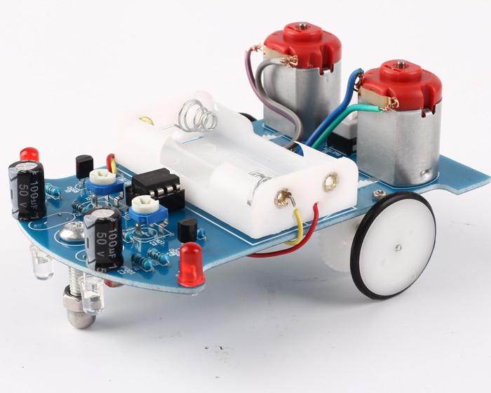
1 . Introduction There is a 6mm wide black runway in the white field.this tracking car can drive along the black runway automatically.no matter how the runway is bent, the car can be driven automatically. We all know that the reflectivity is different when the light source to the white objects and black objects.here we use red light source.the light is reflected through the ground to the photoresistor.by detecting the resistance of the photosensitive resistor can determine whether the car is driving in the white area.if the detection is black runway, then the car to change the direction of driving and motor will slow down or even stop and Red LED OFF on PCB front side.drive the car in the opposite direction so that the car is always running along the runway.. Overview PCB Size:04*7*.6mm Installation dimension:04*7*55mm Work Voltage:3V 3. Schematic
2 4. Component listing NO. Component Name PCB Marker Parameter Qty Remarks Electronic Component LM393 IC DIP-8 IC Socket IC DIP-8 3 Electrolytic Capacitor C,C 00uF 4 Potentiometer R,R 03 0K 5 Metal Resistance Film R5,R6,R,R 5ohm 4 6 Metal Resistance Film R7,R8 K 7 Metal Resistance Film R9,R0 0ohm 8 Photoresistor R3,R4 CDS5 9 Red LED D,D 5mm Red Shell,Red Light 0 White LED D4,D5 5mm White Shell,Red Ligth S8550 Q,Q TO-9 Self-Locking switch S 6*6mm M,M JD3-00 Mechanical Part 3 DC Motor 4 Wheel 4mm 5 Tires 4mm 6 Axle D*30mm 7 Gasket D.0mm 6 8 Three-way sleeve D.5mm 4 9 Gear Dmm 0 Worm D5mm Screw D.*8mm 4 Motor Screw(Black) D.7*4mm 4 3 Gaster Screw M5*0mm 4 Gaster Nut M5 5 Gaster Screw Cap M5 Non-essential Other Component 6 Cable 6mm 4 7 Battery Case AA* With adhesive 8 PCB D-5 04*7*.6mm

3 5. Components >.pcs LM393 DIP-8 >.pcs IC Socket DIP-8 3>.pcs 00uF Electrolytic Capacitor 4>.pcs 0K Potentiometer 5>.4pcs 5ohm Metal Film Resistance 6>.pcs K Metal Film Resistance 7>.pcs 0ohm Metal Film Resistance 8>.pcs Photoresistor 9>.pcs 5mm Red LED 0>.pcs 5mm White LED >.pcs TO-9 S8550 >.pcs 6*6 Self-Locking switch 3>.pcs DC Motor 4>.pcs Wheel 3
4 5>.pcs Tires 6>.pcs Axle 7>.6pcs Gasket(Non-essential) 8>.4pcs Three-way sleeve 9>.pcs Gear 0>.pcs Worm >.4pcs Screw >.4pcs Motor Screw(Black) 3>.pcs Mecanum wheels Screw 4>.pcs Mecanum wheels Nut 5>.pcs Mecanum wheels Screw Cap 6>.4pcs 6mm Cable 7>.pcs AA* Battery Case(Not shown in the picture) 8>.pcs PCB 6. Installation Steps 4
5 >.Install circuit.. Install metal film resistor,dip-8p IC socket,self-locking switch,potentiometer,s8550,electrolytic capacitor,5mm Red LED on PCB according to mark on PCB... Pay attention to the direction of IC Socket... In addition to facilitate debugging, don t install IC LM393 temporarily 5

6 . Install Mecanum wheel.. PCB placed in front.the support bolts of the caster are inserted into the hole, tighten the nuts screwed into the caster, and finally fit the caster and tighten. 6


7 .3 Install photoresistor and white LED on PCB reverse.but please make sure the distance is about 5mm between top of mecanum wheel(top of screw cap top) and photoresistor/led. 7

8 .4 Install battery case. 8
9 .5 Test..5. Install pcs AA battery..5. Press on switch.if pcs white LED ON,the installation is successful.if LED off,please check the welding.pay attention to the direction of LED and other component and check pseudo Soldering. >.Install mechanical parts. Install the four gaskets on the circuit board. The role of the gasket is to increase the gap between the axle and the circuit board, so that the gear mounted on the shaft has enough rotation space. First insert a M. * 8 screw from the front of the board into the mounting hole, place a gasket from the back of the circuit board on the screw. Clamp the gasket with a small pliers, turn the screw with a small screwdriver until the gasket is close to the circuit board at last. 9

10 0

11 . Insert a steel shaft from the center hole of the wheel and note that the direction is inserted from one side of the raised sleeve of the wheel. It is better to insert the steel shaft parallel to the smooth side of the wheel..3 Put a three-way sleeve into the steel shaft, close to the wheel, and then a gasket into the steel shaft, close to the three-way sleeve, installed in place, toggle three-way sleeve, should be flexible. Otherwise appropriate to increase the gap between them.install tires..4 Place a gear into the steel shaft in the center of the steel shaft.

12 .5 Put a three-axis sleeve into the end of the steel shaft so that the car side of the wheel assembly to complete. Holding the wheel by hand, keep the steel shaft level, adjust the position of the three-way sleeve on the end of the steel shaft. The gears on the steel shaft should fall into the gear slot, otherwise the gear position should be adjusted until it meets the requirements. Finally, the two shafts on the steel shaft are fitted into the screw projections of the fixed washers and tightened with a small screwdriver so that the wheel assembly is installed. Install the other side of the wheel assembly in the same way.


13 3

14 .6 Install Motor Insert a worm into the motor shaft,then thought worm from the front of the circuit board to others.use two small screws to hold the motor.pay attention to the direction of motor.contact motor and PCB by cable. It can reversed the wire of motor if motor move on the contrary when power on. 4

15 3. Test. 3. Power on.check S8550 or 0ohm resistor if motor don t move. 3. Install LM393(Pay attention to the direction of IC). 7.Finished Tracking Car 5

16 6

17 7

18 8

19 9
WHDTS Smart Car Kit D2-5 Electric Soldering DIY Kits
 D2-5 Smart Car Kit Intructions Foreword Thank you for choosing the D2-5 smart car kit. This kit gives you an initial understanding of the principles and techniques of automatic control. We hope you can
Ljunggren Audio Roll Your Own Penta
 Ljunggren Audio Roll Your Own Penta Version: Penta 1.0 Bills Of Material Bold = PCB1, The rest = PCB2 Type Parts Des cription Pow er header Qty Value 1 2x5pin POWER Euro pow er connector Jack 1 3.5mm J1,
ASSEMBLY INSTRUCTIONS FOR NEW FK109 4 LED Railroad Crossing Flasher Kit WITH ADJUSTABLE FLASHING SPEED CONTROL with 4 Red 3mm Leds
 ASSEMBLY INSTRUCTIONS FOR NEW FK109 4 LED Railroad Crossing Flasher Kit WITH ADJUSTABLE FLASHING SPEED CONTROL with 4 Red 3mm Leds Description: Very easy to build, The FK109 Led Flasher kit makes the perfect
2xVCX version 1.0. Calibration instructions can be found on the last page. Capacitor bypass MLCC X7R mm pin pitch
 Produced by: Roll Your Own ljunggrenaudio.com Schematic & PCB Design by: KYMATICA DEVICES www.kymatica.com xvcx version.0 Bills Of Material Bold = PCB C C C3 C4 C5 C6 C7 C8 C9 C0 C C C3 C4 CON D D D3 D4
Schematic VCC J1 1 CON1 +5V D26 D25 D7 D8 D9 D10 D11 D12 D19 D20 D21 D22 D23 D24 D1 D2 D3 D4 D5 D6 D13 D14 D15 D16 D17 D18 R4 100R R2 100R R6 100R
 Schematic +5V S D1 D2 D3 D4 D5 D6 D7 D8 D9 D10 D11 D12 D19 D20 D21 D22 D23 D24 D13 D14 D15 D16 D17 D18 D25 D26 R1 4K7 R2 100R Q1 9014-PNP C1 47uF R3 4K7 R4 100R Q2 9014-PNP C2 47uF R5 4K7 R6 100R Q3 9014-PNP
IDC-136II-KIT 136kHz DC RX Assembly Guide
 IDC-136II-KIT 136kHz DC RX Assembly Guide ICAS Enterprises May 2 nd,2016 The IDC-136II-KIT is a 136kHz direct conversion receiver. Most of the SDR software can be used with this receiver. It is quite easy
~Dashboard Digital Voltmeter~
 ~Dashboard Digital Voltmeter~...November, 2002 This project is helpful to anyone who drives an automobile. I had found this project at the local libary... in an old publication. I made it and it worked
Norcal Power/SWR Meter Assembly & Operating Manual. Revision 1D 10/15/2008
 Norcal Power/SWR Meter Assembly & Operating Manual Revision 1D 10/15/2008 Copyright 2008 NorCal QRP Club Page 1 of 21 Contents CONTENTS...2 INTRODUCTION...3 SPECIFICATIONS...3 ASSEMBLY...4 OPERATING GUIDE...15
MONGOOSE. Introduction. < blueroomelectronics > Assembly Instructions. Mongoose was designed as an introduction to Mechatronics.
 MONGOOSE Assembly Instructions Introduction Mongoose was designed as an introduction to Mechatronics Page 1 of 12 Before you start The Mongoose is a complex kit and skipping instructions is not advised,
Electronic Dice Kit MitchElectronics 2019
 Electronic Dice Kit MitchElectronics 2019 www.mitchelectronics.co.uk CONTENTS Schematic 3 How It Works 4 Materials 5 Construction 6 Important Information 7 Page 2 SCHEMATIC Page 3 SCHEMATIC EXPLANATION
Build Instructions and User Guide
 Build Instructions and User Guide Getting Started To build the Rock Drill 4069 you will need: Solder Wire Cutters Soldering Iron Small pliers The kit is suitable for beginners or more experienced builders
HW-8-LM386 Audio Amplifier Board Assembly Instructions
 This LM386 based audio amplifier kit was designed to replace the small audio amplifier board in the Heathkit HW-8 transciever. The result is the ability to drive regular modern day 8 ohm headphones or
IV-11 VFD tube clock Assembly instructions v1.2.2
 IV-11 VFD tube clock Assembly instructions v1.2.2 Designer: Website: E-mail: Yan Zeyuan. China http://www.nixieclock.org yanzeyuan@qq.com 2017-01-26 NCH Attention Attention: Warning: Warning: Warning:
Ljunggren Audio Roll Your Own Optodist
 Ljunggren Audio Roll Your Own Optodist Version: Optodist/VCA.0 Bill Of Material TYPE PART VALUE PCS NOTE Resistor R,R 0R Resistor R5,R0 K Resistor R3,R4 0K Resistor R,R9 68K Resistor R 00K Resistor R3
General Purpose Flasher Circuit
 General Purpose Flasher Circuit By David King Background Flashing lights can be found in many locations in our neighbourhoods, from the flashing red light over a stop sign, a yellow warning light located
RGB Alarm Clock. -Color Alarm Clock-
 RGB Alarm Clock -Color Alarm Clock- Table of Contents Preamble:...2 List of parts...3 Components...5 Parts and belongings...5 Clock Board Assembly...8 Identification of SMD parts:...0 The power supply
LED PICTURE FRAME KIT
 ESSENTIAL INFORMATION BUILD INSTRUCTIONS CHECKING YOUR PCB & FAULT-FINDING MECHANICAL DETAILS HOW THE KIT WORKS MAKE A DISPLAY OF YOUR MOST TREASURED PHOTOGRAPH WITH THIS LED PICTURE FRAME KIT Version
The ability to make basic voltage and resistance measurements using a digital multimeter
 Seventh Circle Audio C84 Microphone Preamp Based on the innovative Double Balanced Microphone Amplifier circuit published by Graham John Cohen in 1984, the C84 microphone preamp offers exceptional performance
ROBOT SOUND REVERSING CAR KIT C-9802
 ROBOT SOUND REVERSING CAR KIT TOOLS you'll need Alimentation 2 batteries 1,5 V AA (not included) You will find fun to learn electronics and mechanics assembling robot by reversing sound. This is a simple
SCA-80(Q) C11 REPLACEMENT ASSEMBLY MANUAL
 C11 REPLACEMENT ASSEMBLY MANUAL") SCA-80(Q) C11 REPLACEMENT ASSEMBLY MANUAL 2014-2016 AkitikA, LLC All rights reserved Revision 1p05 July 3, 2016 Page 1 of 15 Table of Contents Table of Contents... 2 Table of Figures... 2 Section 1: About
SCA-80(Q) C11 REPLACEMENT ASSEMBLY MANUAL 2014-2016 AkitikA, LLC All rights reserved Revision 1p05 July 3, 2016 Page 1 of 15 Table of Contents Table of Contents... 2 Table of Figures... 2 Section 1: About
PSL2 Assembly guide. PSL2 Assembly guide. Resistors. Test pins. Document revision 1.1 Last modification : 30/05/08
 Safety warning THIS KIT IS NOT FOR BEGINNERS! This kit is main powered and use potentially lethal voltages. Under no circumstance should someone undertake the realisation of this kit unless he has full
D6, D7, D8, D9, D12, D13, D14, D15, D16, D17, D18, D19. Schottky rectifier diode. 1N5817-1N5819 or SB130
 Roll Your Own ljunggrenaudio.com Altered States version 1.0 Bills Of Material Qty Value 12 1N4148 2 1N5818 4 1N750 4.7V 4 220p Device Diode Diode Zener diode Capacitor 30 100n 4 15p 8 560p 1 5x2 pin Capacitor
Linear Stepper Driver v0.9.2 Assembly Instructions
 Linear Stepper Driver v0.9.2 Assembly Instructions Here's what's included in the kit: 1x Printed Circuit board 1x Heatsink bracket 5x 0.1uF capacitors 1x 6-pin ISP header 1x 10-pin configuration header
22K (red red orange gold) 1pcs. 33K (orange orange orange gold) 5pc. 2.7 M (green violet red gold) 2pc.
 1pcs. 33K (orange orange orange gold) 5pc. 2.7 M (green violet red gold) 2pc.") TURNING FROG Long pliers, soldering, soldering iron stand with sponge, 2 AA batteries, one 9V battery, Tin, diagonal cutting pliers Turning Frog is a robot that uses a microphone as a detector. When microphone
TURNING FROG Long pliers, soldering, soldering iron stand with sponge, 2 AA batteries, one 9V battery, Tin, diagonal cutting pliers Turning Frog is a robot that uses a microphone as a detector. When microphone
IV-3 VFD Shield for Arduino. Assembly Manual
 June 2014 Table of Contents 1 Overview Features Applications 3 3 3 2 Assembly Hints 4 3 PCB Overview 5 4 Circuit Diagram 6 5 Assembly Diodes and IC socket Electrolytic capacitors Ceramic capacitors 10K
ITEM PART NO DESCRIPTION QTY LOCATION
 TRANSISTOR 1 01-24001A0-A00 DIODE WIN4001 1 D206 2 01-3197130-A00 TRANSISTOR 2SC1971 1 Q2 3 01-320533A-A00 TRANSISTOR 2SC2053 1 Q3 4 01-3240830-A00 TRANSISTOR 2SC2408 1 Q4 SMT TRANSISTOR 1 02-22838D0-A00
Tri Boost Kit Instructions
 Tri Boost Kit Instructions Click here for older triboost version instructions(no 3-way LED) Parts Checklist...page 2-3 Schematic.....page 4 Populating and mounting the circuit board..page 5-14 Wiring Diagram.......page
CAPI BB2521 Build Guide & BOM
 This is a very simple build. I only have a few tips and things to look out for. I do recommend following these steps due to the diode/transistor relationship. 1. Install the three ceramic caps. If you
HW-8-LM386 Audio Amplifier Board Assembly Instructions
 This LM386 based audio amplifier kit was designed to replace the small audio amplifier board in the Heathkit HW-8 transciever. The result is the ability to drive regular modern day 8 ohm headphones or
Assembly Manual for New Control Board 22 June 2018
 Assembly Manual for New Control Board 22 June 2018 Parts list Arduino 1 Arduino Pre-programmed 1 Faceplate Assorted Header Pins Full Board Rev A 9 104 capacitors 1 Rotary encode with switch 1 5-volt regulator
EQ73 Parts list Reference Value Qty Description Marking Dim Manuf. YEL-VIO-BLK-GLD-BRN RED-RED-BRN-BRN RED-RED-BLK-BLK-BRN GRN-BLU-BRN-BRN
 EQ73 Parts list (1) Reference Value Qty Description Marking Dim (2) Manuf. R52, R53 47R 2 Resistor 1%, 1/4W YEL-VIO-BLK-GLD-BRN R45, R46 180R 2 Resistor 5%, 1/2W R23, R24 220R 2 Resistor 1%, 1/4W RED-RED-BRN-BRN
FX Type: Filter 2.35" W x 3.35" H Terms of Use: HoneyDripper HoneyDripper
 HoneyDripper FX Type: Filter Based on the Colorsound Dipthonizer madbeanpedals 2015 Version Previous Versions: http://www.madbeanpedals.com/projects/archive/filtermod/ 2.35" W x 3.35" H Terms of Use: You
HercuLine 2000 Series Gear Kit Replacement Instructions
 HercuLine 2000 Series Gear Kit Replacement Instructions 51452443-501 Document Information Form: 62-86-33-35 Effective: 5/04 Supersedes: None Summary This kit contains all the gears, idler shafts and hardware
ECO-6 & Installation Manual
 ECO-6 & Installation Manual For the SPA4-RFR Upgrade Kit To upgrade SPA4 amplifiers v1.00 & v1.01 to v2.0 Some sections also apply to the PA1, PA2, and PA3 14 August 2015 2015 by Ralph Hartwell Spectrotek
SM361 RIG SWITCH CONSTRUCTION MANUAL
 SM361 RIG SWITCH CONSTRUCTION MANUAL Document ver 1, For software release ver 1.1 May 27, 2016 Controls the power of 12V equipment while a vehicle is in use Product Development by: SM361 RIG SWITCH OVERVIEW
Wheel Angle Sensor Kit Installation
 Wheel Angle Sensor Kit Installation Item Component Part Number Qty 1. Bracket Kit, WAS 200-0535-01 1 2. WAS Assembly 200-0468-01 1 3. Instruction Guide 602-0467-01 1 602-0467-01-A Overview Always shut
BUMP AND SPIN KIT ESSENTIAL INFORMATION. Version 1.0 PROGRAM AND DESIGN YOUR OWN BUGGY WITH THIS
 ESSENTIAL INFORMATION BUILD INSTRUCTIONS CHECKING YOUR PCB & FAULT-FINDING MECHANICAL DETAILS HOW THE KIT WORKS PROGRAM AND DESIGN YOUR OWN BUGGY WITH THIS BUMP AND SPIN KIT Version 1.0 Build Instructions
C capacitance, 91 capacitors, codes for, 283 coupling, polarized and nonpolarized,
 Index Numbers and Symbols 555 timer, 164 166 making sound using, setting output speed of, 166 167 using for reaction game speed, 260 261 μf (microfarad), 92 Ω (ohms), 7, 70 A A (amperes), 7 AC (alternating
QRPGuys Digital RF Probe
 QRPGuys Digital RF Probe First, familiarize yourself with the parts and check for all the components. If a part is missing, please contact us and we will send one. This kit contains seventeen 1206 size
Total solder points: 93 Difficulty level: beginner advanced 10 LED MONO VU METER K4304 ILLUSTRATED ASSEMBLY MANUAL
 Total solder points: 93 Difficulty level: beginner 1 2 3 4 5 advanced 10 LED MONO VU METER K4304 Add a visual readout to your existing or new equipment. ILLUSTRATED ASSEMBLY MANUAL H4304IP-1 Features &
Collosalus 2015 FX Type: Flanger 3.25 W x 2.9 H
 Collosalus 2015 FX Type: Flanger Based on the MXR 117 Download the previous version documentation here: http://www.madbeanpedals.com/projects/collosalus/collosalus.zip 3.25 W x 2.9 H B.O.M. Resistors Caps
ELECTRIC FENCE ENERGIZER SERVICE MANUAL MODEL 950 SERVICE MANUAL FOR OLLI 950 FENCE ENERGIZERS
 ELECTRIC FENCE ENERGIZER MODEL 950 SERVICE MANUAL Service Manual for OLLI 950 Page 1/16 Date 20.10.2014 Table of Contents...1 1. IMPORTANT SAFETY INSTRUCTIONS...2 2. SPECIFICATIONS...3 3. CONSTRUCTION...4
DTC B0228, B0413, B0423, Or B3779
 2007 Chevrolet Silverado 1500 : Heating, Ventilation, & Air Conditioning > HVAC Systems - Manual > Diagnostic Information And Procedures > DTC B0228, B0413, B0423, Or B3779 DTC B0228, B0413, B0423, Or
DIY Synth Kit - Manual STUTTER SYNTH
 DIY Synth Kit - Manual STUTTER SYNTH Welcome to the DIY Synth - Manual This is a step-by-step guide to making your own electronic Synth. All you will need is your hands and your DIY Synth kit which includes
J&M Mustang Rear Adjustable Lower Control Arms Installation Guide (99-04)
") J&M Mustang Rear Adjustable Lower Control Arms Installation Guide (99-04) 1. Required Tools: 1.1. 3/8 ratchet 1.2. 1/2 ratchet 1.3. 18mm deep socket 1.4. 18mm standard socket (optional) 1.5. 19mm open
J&M Mustang Rear Adjustable Lower Control Arms Installation Guide (99-04) 1. Required Tools: 1.1. 3/8 ratchet 1.2. 1/2 ratchet 1.3. 18mm deep socket 1.4. 18mm standard socket (optional) 1.5. 19mm open
Section 26: Capacitors, Resistors, Potentiometers, Trimmers. Capacitors Resistors Potentiometers Trimmers...
 Section 26: Capacitors, Resistors, Potentiometers, Trimmers Sub-Section Page Capacitors.....................................................680 Resistors......................................................681
openqrp Transceiver Parts List By Functional Section 1/11/2014 Using openqrp PC Board Rev D, 40M Version
 openqrp Transceiver Parts List By Functional Section 1/11/2014 Using openqrp PC Board Rev D, 40M Version Section 1 AGND Schematic Page 2 R37 [I8] 10K 1/8W Resistor (Brown Black Orange) R38 [J9] C80 [J9]
Athearn Pacific Digital Sound Decoder Installation Notes
 New Dimensions in Digital Sound Technology TM APPLICATION NOTE Overview This application note describes how to install a DSD-100LC Digital Sound Decoder into the Athearn Pacific Locomotive. All of the
Total solder points: 187 Difficulty level: beginner advanced. Code lock K6400 ILLUSTRATED ASSEMBLY MANUAL
 Total solder points: 187 Difficulty level: beginner 1 2 3 4 5 advanced Code lock K6400 Ged rid of those old fashioned keys ILLUSTRATED ASSEMBLY MANUAL H6400IP-2 Features & Specifications Features: More
Circuit Basics and Components
 Circuit Basics Electric circuits are arrangements of conductors and components that permit electrical current to flow. A circuit can be as simple as a battery and lamp or as sophisticated as a computer.
AMM-TE ammeter Manual
 AMM-TE ammeter Manual I. Kit Details Kit Name: Ammeter Kit Kit Model: AMM-TE PCB Size: 70.6 * 39mm Screen size: 51 * 24mm Electrical parameters Operating voltage: DC5 Operating Current: 35mA Accuracy:
Assembly Manual for ISDR-136-KIT
 Assembly Manual for ISDR-136-KIT ICAS Enterprises Last Updated March 21 st, 2012 This SDR receiver kit is intended for the 136kHz band. The kit utilizes DIP IC components (no SMD) so that even a beginner
K3500 MULTIFUNCTION CAR COURTESY LIGHT. Specifications
 Total solder points: 87 Difficulty level: beginner 1 2 3 4 5 advanced MULTIFUNCTION CAR COURTESY LIGHT K3500 Never look for the ignition switch in the dark again. Specifications switch-off delay: adjustable
Engineering Innovation Center EIC. Electronic Component Selection
 Electronic Component Selection Why is it important to choose the right part? Cost Efficiency This PCB fire caused by choosing the wrong capacitor Cap wasn t rated for voltage and failed short >100 Amps
3D PRINTER. Pack 09. Anything you can imagine, you can make! 3D technology is now available for you at home! BUILD YOUR OWN
 BUILD YOUR OWN Pack 09 Anything you can imagine, you can make! 3D PRINTER Compatible with Windows 7 & 8 Mac OS X 3D technology is now available for you at home! www.model-space.com BUILD YOUR OWN 3D PRINTER
www MK-Electronic de EPSON LQ2170 Spares Guide Version 3 Page 1
 REF PART NO DESCRIPTION REMARKS QTY 100 1025018 HOUSING ASSY., LOWER 1 101 1025039 COVER, FRONT 1 102 1025041 HOUSING, UPPER 1 103 1025027 COVER, PRINTER, REAR 1 104 1025024 COVER ASSY., PRINTER 1 105
#92 DISC BRAKE ADJUSTMENTS # BRAKE MONITOR
 #92 DISC BRAKE ADJUSTMENTS #102-091 BRAKE MONITOR Page 1 of 11 HOLLISTER-WHITNEY DISC BRAKE WITH BRAKE MONITOR ADJUSTMENT PROCEDURE Page 2 of 11 HOLLISTER-WHITNEY DISC BRAKE WITH MONITOR SWITCH ADJUSTMENTS
Mableaudio Company limited
 Mableaudio Company limited Web: www.mableaudio.com [5E3 assembly manual] Tel:0086-755-83996326 fax:0086-755-83996326 Contact: Ms Mable mable@mableaudio.com WARNING! This amp operates at voltages that may
Pan & Tilt Kit (REV-C)
") PANDORA Pan & Tilt Kit (REV-C) www.dpcav.com The items shown in the photo below are provided in the kit. Be sure to check for missing parts BEFORE your start assembly. Figure 2, Kit Contents The following
PANDORA Pan & Tilt Kit (REV-C) www.dpcav.com The items shown in the photo below are provided in the kit. Be sure to check for missing parts BEFORE your start assembly. Figure 2, Kit Contents The following
White Light CLASSIC PEDAL KIT. Assembly Instructions WHEN YOU CAN T BUY IT BUILD IT. StewMac RARE / VINTAGE / HARD TO GET
 Sheet #i-2206 Updated 5/18 StewMac White Light CLASSIC PEDAL KIT Kit case is unpainted IN COLLABORATION WITH EarthQuakerDevices Assembly Instructions The White Light Overdrive is based on vintage overdrives
solutions for teaching and learning
 SCR/Thyristor Training PCB Component List and Instructions Version 2 PCB layout Constructed PCB SCR Training and Development PCB Page 1 Schematic Diagram Description This system has been specifically designed
USING STANDARD x1 and x10 OSCILLOSCOPE PROBES WITH THE TEKTRONIX 222PS OSCILLOSCOPE:
 USING STANDARD x1 and x10 OSCILLOSCOPE PROBES WITH THE TEKTRONIX 222PS OSCILLOSCOPE: & REPLACING the 222PS Battery Dr. H. Holden 2013. WARNING: The original Tektronix P850 and P400 probes(now hard to get)
BehringerMods.com. Instructions for modification of Behringer DCX analog inputs and outputs
 BehringerMods.com Instructions for modification of Behringer DCX analog inputs and outputs The following instructions will cover the details of fully modifying a unit with analog output and analog input
Arlo Power Distribution Board Kit Rev B (#28996)
") Web Site: www.parallax.com Forums: forums.parallax.com Sales: sales@parallax.com Technical: support@parallax.com Office: (916) 624-8333 Fax: (916) 624-8003 Sales: (888) 512-1024 Tech Support: (888) 997-8267
Web Site: www.parallax.com Forums: forums.parallax.com Sales: sales@parallax.com Technical: support@parallax.com Office: (916) 624-8333 Fax: (916) 624-8003 Sales: (888) 512-1024 Tech Support: (888) 997-8267
MAX712 Linear-Mode Evaluation Kit
 9-2366; Rev ; /02 MAX72 Linear-Mode Evaluation Kit General Description The linear-mode evaluation kit (EV kit) is a complete battery charger for nickel metal hydride (NiMH) and fast-charge nickel-cadmium
IR Gun Assembly Instructions
 IR Gun Assembly Instructions Rev 1.01 SenselessDevices.com 1 Description The IR Gun is part of a shooting Arcade project. Together with the target kits, a variety of shooting galleries can be constructed.
Illustrated Parts List for GPU-400
 Illustrated Parts List for GPU-400 Series 500082-4xx 28.5 Volts, 400 Amps Section 1 Illustrated Parts List 1) Explanation of Parts List Arrangement The parts list is arranged so that the illustration will
SCREEN ROOM ITM./ART MODEL#L-GZ938PCO-B/L-GZ938PCO-B2 ASSEMBLY INSTRUCTIONS
 SCREEN ROOM ITM./ART. 470260 MODEL#L-GZ938PCO-B/L-GZ938PCO-B2 ASSEMBLY INSTRUCTIONS IMPORTANT: RETAIN FOR FUTURE REFERENCE. READ CAREFULLY. Please check with your local governing authority / local municipal
Modifying the Spectrian 2.4GHz PA
 Modifying the Spectrian 2.4GHz PA Two types of modification: 1. Basic required for the PA to function 2. Enhancements additional monitoring and functionality The unit normally mounts vertically in a rack.
These instructions show how to build the Remote Controlled Fart machine Sound Kit.
 Remote Controlled Fart Machine Assembly Instructions These instructions show how to build the Remote Controlled Fart machine Sound Kit. Tools Required Drill with 7/64, 3/16, and ¼ drill bits. Holt melt
Cabin Light. Hi All, 1
 Hi All, My friend Rudolf set me a challenge for his 36331 electric locomotive, wanting Telex couplers fitted. When I opened up the locomotive I discovered there is very little room to add extra components
Assembly Instructions for the KA Electronics Flat MM Phono Preamplifier
 Assembly Instructions for the KA Electronics Flat MM Phono Preamplifier Install IC sockets Flat MM Phono Preamp PC Board Stuffing Guide Place the PC Board on the bench silkscreen side face up. Drop six
Simple Eurorack Row. Kit Builder's Guide. 4mspedals.com
 Simple Eurorack Row Kit Builder's Guide 4mspedals.com ' Simple Eurorack Row This guide is for building a single-row eurorack case with a power supply. When completed, the case is ready to accept eurorack
Bill of Materials: Car Battery/charging system diagnostics PART NO
 Car Battery/charging system diagnostics PART NO. 2192106 You can hook up the kit's test leads directly to the car battery (with engine off) and see whether battery voltage is ok (green LED on) or low (yellow
Replacing gauge lamps with LED's
 Replacing gauge lamps with LED's To pull the gauges just to replace a small bulb is quite a nuisance and the existing bulbs are not all that bright and easily blow. It is thus worthwhile replacing them
(2 DPDT 2 4 X
 Dynaco ST-120 with VTA driver board Kit instruction manual Triode/Pentode version Congratulations on your purchase of the Dynaco ST-120 with VTA driver board kit. Every effort has been made to give you
Solar Inverter/Charger
 Solar Inverter/Charger PV1100 PLUS Table of Contents 1. General Information...1 1.1 Brief Introduction. 1 1.2 Inverter Schematic Diagram.1 1.3 Inverter Components Instructions... 2 2. Fault Code...3 3.
CHAPTER 2. Current and Voltage
 CHAPTER 2 Current and Voltage The primary objective of this laboratory exercise is to familiarize the reader with two common laboratory instruments that will be used throughout the rest of this text. In
Soldering Pi2Go Lite. Soldering the Line-Follower PCB
 Soldering Pi2Go Lite First check which version of the main PCB you have. It is marked above the left motor "Pi2Go-Lite v1.x". There are minor changes to some parts of the build. v1.0 (initial release)
Arlo Power Distribution Board Kit Rev B (#28996)
") Web Site: www.parallax.com Forums: forums.parallax.com Sales: sales@parallax.com Technical: support@parallax.com Office: (916) 624-8333 Fax: (916) 624-8003 Sales: (888) 512-1024 Tech Support: (888) 997-8267
Web Site: www.parallax.com Forums: forums.parallax.com Sales: sales@parallax.com Technical: support@parallax.com Office: (916) 624-8333 Fax: (916) 624-8003 Sales: (888) 512-1024 Tech Support: (888) 997-8267
SGL2 Solar LED landscape Lamp. Instruction manual
 SGL2 Solar LED landscape Lamp Instruction manual Table of Contents 1. Overview... 1 2. Product Icon... 1 3. Product Features... 2 4. Working Principle... 2 5. Technical Specifications... 3 6. Product List...
DCX2496 Linear Power Supply mod by
 DCX2496 Linear Power Supply mod by Construction Guide Linear Power Supply for the DCX2496 Introduction. One of my more rewarding modifications to the DCX2496 was the replacement of the stock I/O board
UK-electronic 2012/15
 UK-electronic 2012/15 Manual for the Kit Zentaurus Rev 1.21 with buffer or True bypass Page 1...Cover Page 2..3...Allocations, basics Page 4...5...Bill of material Page 6...7...Soldering the pcb Page 8...Building
BREADBOARD PLUGIN POWER SUPPLY # REV3 +5VDC
 BREADBOARD PLUGIN POWER SUPPLY # 400039 REV3 +5VDC INDEX A. Learn Power Supply Design with a hands on approach B. General Information and Features C. Assembled Picture of the Breadboard plug-in power supply
An ISO 9001 Company. BOP 1KW-MG FIRMWARE RETROFIT KIT
 INSTRUCTION MANUAL 1. DESCRIPTION KEPCO An ISO 9001 Company. BOP 1KW-MG FIRMWARE RETROFIT KIT BOP 1KW-MG RETROFIT KIT 219-0562 Kepco KIT 219-0562 contains the PROMs used to upgrade the firmware for BOP
Part Code Part Name Ref No. Category Qty Remark
 Rev.D C060 Part Code Part Name Ref No. Category Qty Remark 1005501 HOSING ASSY., LOWER 100 Case 1 1005558 FOOT 101 Case 4 1005502 HOUSING ASSY., UPPER 102 Case 1 1005475 HOUSING, FRONT 103 Case 1 1005504
Transfer Valve Actuator Overhaul Instructions
 Rotary Style Transfer Valve Actuators Overhaul Instructions Form No. F-1031 Section 2315 Issue Date 12/10/99 Rev. Date 11/02/11 Table of Contents Introduction.................................. 1 Safety
GoldSTEM.org. Growing the Future
 GoldSTEM.org Growing the Future GoldSTEM Arduino 4WD 4 Wheel Drive Smart Car Robot Chassis for STEM Development Assembly Instructions. GoldSTEm.org Smart Car Chassis Assembly instructions V1. tm 11-20-16
Real Square 2011 RS400PRO Quick Start User Instructions v. 10.1
 Real Square 2011 RS400PRO Quick Start User Instructions v. 10.1 Technical Help: Please call 540-483-4442, Monday-Friday 8:00AM-5:30PM or e-mail questions to tech@drpperformance.com. RS400PRO Contents:
FX TYPE: DISTORTION Based on the Suhr Riot PCB artwork m2011 madbeanpedals Special thanks to culturejam! Release date: REVISED
 http://www.madbeanpedals.com presents uproar FX TYPE: DISTORTION Based on the Suhr Riot PCB artwork m2011 madbeanpedals Special thanks to culturejam! Release date: 01.30.11 REVISED 02.08.11 This version
SR-400 CYCLONE TO SR-400 CYCLONE II UPGRADE WRITTEN BY WDØGOF
 SR-400 CYCLONE TO SR-400 CYCLONE II UPGRADE WRITTEN BY WDØGOF This upgrade assumes you are starting with a first production run Cyclone. As you proceed you may find some of the modifications have already
Assembly and User Guide
 Assembly and User Guide 2 Amp Adjustable Electronic Load 30V and 20 Watts Max Powered by: 9V Battery Pico Load is a convenient constant current load for testing batteries and power supplies. The digital
Instruction Manual. High Lift Hand Truck
 Instruction Manual High Lift Hand Truck Note: The Owner/Operator must read carefully and understand all the information presented here before operation. CONTENT 1. Specification. 2 2. Safety Instructions...
urevco Universal Revolution Counter
 urevco Universal Revolution Counter www.urevco.com MT-EMB Via Primo Maggio 51/E 10035 Mazzè (TO) IT marco.testa@mt-emb.com +393349562812 General Description urevco is a device that allows to convert a
100W SUBWOOFER KIT. Total solder points: 383 Difficulty level: beginner advanced K8077 ILLUSTRATED ASSEMBLY MANUAL
 100W SUBWOOFER KIT Powerful bass from a small cabinet thanks to the dual speaker principle Total solder points: 383 Difficulty level: beginner 1 2 3 4 5 advanced K8077 ILLUSTRATED ASSEMBLY MANUAL H8077IP-1
GENERAL INFORMATION. Wheel Alignment Theory & Operation
 Fig. 1: Checking Steering Linkage GENERAL INFORMATION Wheel Alignment Theory & Operation ADJUSTMENTS NOTE: This article is intended for general information purposes only. This information may not apply
PM-200 POWER SUPPLY MODULE v3.2 ASSEMBLY & INSTALLATION INSTRUCTIONS
 PM-200 POWER SUPPLY MODULE v3.2 ASSEMBLY & INSTALLATION INSTRUCTIONS WARNING: Voltages inside the amplifier CAN & WILL KILL YOU! You MUST know how to work around HIGH VOLTAGE safely. If you do not, get
Kit1 300B Edition. Single Ended Triode 8 Watt. Construction Manual & User Guide Volume One
 Kit1 300B 2014 Edition Single Ended Triode 8 Watt Construction Manual & User Guide Volume One Contents Section 1: Receiving your kit...2 Section 2: The Mechanical section Preparation... 3 Tang Strips...
Atlas Silver Series HO RS-3 (2014 Release) Tsunami Digital Sound Decoder Installation Notes
 Tsunami Digital Sound Decoder Installation Notes") Atlas Silver Series HO RS-3 (2014 Release) Tsunami Digital Sound Decoder Installation Notes Overview This application note describes how to install a TSU-AT1000 Digital Sound Decoder into an Atlas Silver
Atlas Silver Series HO RS-3 (2014 Release) Tsunami Digital Sound Decoder Installation Notes Overview This application note describes how to install a TSU-AT1000 Digital Sound Decoder into an Atlas Silver
Wheel Angle Sensor Kit Installation
 Wheel Angle Sensor Kit Installation Item Component Part Number Qty 1. Bracket Kit, WAS 200-0572-01 1 2. WAS Assembly 200-0468-01 1 3. Instruction Guide 602-0456-01 1 602-0456-01-A Overview Always shut