Modifying the Spectrian 2.4GHz PA
|
|
|
- Domenic Richard
- 5 years ago
- Views:
Transcription
1 Modifying the Spectrian 2.4GHz PA Two types of modification: 1. Basic required for the PA to function 2. Enhancements additional monitoring and functionality The unit normally mounts vertically in a rack. However, the mods will assume that it will rest flat on a table or similar. In these notes, the Top of the unit is the side closest to the power switch. The Bottom is closest to the handle. The Top cover only has a handful of screws holding it on. The Bottom has several dozen. Note that the PA contains a mixture of Philips Head and Torx screws. You will need size T10 (?) and T15 Torx drivers. 1. Basic Modifications 1.1 Removal of Unnecessary Items Remove both covers and front panel. On the Bottom side (RF side), remove the input/mixer board. It s the one in the front corner with only a few components on it. Keep the hardline leads for later. On the top side, remove all of the boards and associated ribbon cables. (The large board is the 48 volt to 24 / 12 volt DC-DC converter. The other board is the supervisory / controller). If you want to add the current metering enhancement, leave the two gold power resistors (0.01 ohm) that are bolted to the chassis. Remove the power switch / circuit breaker. Remove the multi-pin connector on the rear panel. Either desolder or cut the hardline coax right at the connector. The coax will be re-used on the input later. 1.2 Power Supply Mount the three switching supplies to the top panel, centred. Viewed from the front of the PA, the AC connections should be to the left and DC outputs to the right. The supply with both 5V and 12V modules should be at the front. The power supplies have threaded mounting holes. Mounting screws are M4, and must be very short (5mm max thread length). Use washers to limit their penetration if needed. Wire the 5 volt supplies in series using heavy gauge wire capable of carrying the 60A peak current. I only used one of the 12V supplies, leaving the other 12V output unconnected.


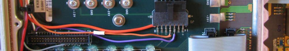
2 To feed the wires into the PA, I cut two slots in the lid and fed the wires through grommets (see photo). It means that, to take the lid off, I first have to disconnect the DC wires from the power supplies.


3 Wire all the AC inputs in parallel. You can then run a power lead straight from that, or add a power switch as per the Enhancements below. 1.3 Cooling The PA requires a LOT of cooling, as it dissipates nearly 1 kw at full power. You need high flow muffin fans or, ideally, a blower with a manifold to couple it to the cooling intake. I used 4 x 85mm 24V muffin fans (one-off lot from ebay). Equally, you could use 12V or 6V, but I d recommend DC fans so that you can do the Cooling Enhancement (slow them down during Rx periods). I used two strips of 12mm x 12mm aluminium angle to hold them in place. To hold the strip in place, there are four bolts, one hole in from each end of each length of angle, going right through the fans and back panel to hold them in place. Each fan is bolted to the alu angle. Wire the fans in series/parallel and connect to 24V or 12V supply as appropriate (or Cooling Controller (Enhancement)). Feed the wires through the hole left by the rear panel multi-pin connector. 1.4 RF Connections The PA has over 43dB of gain, so it s strongly advised to use hardline coax for both input and output. I used UT-141 for output and UT-085 for the input. The input uses the coax recovered from the old input board. I used a solder SMA panel mount socket on the end, recovered from some short leads I had. The output uses a length of UT-141 coax with an SMA solder connector on one end and a screw termination, panel mount N connector on the other. Both connectors are mounted on a bracket made from 25mm x 25mm alu angle mounted to the cooling fan bracket. The hardline is carefully bent to fit through the

 needs to be wired through to the Output Stage Enable input.")

4 hole left by the rear panel multi-pin connector. I had to carefully grind away some of the end fan body so that the leads would fit past it. 1.5 Enable The Enable input puts the PA into transmit state when it is grounded. The input is through an RCA connector on the same bracket as the RF connections. Wire the RCA connector to the point where the thin orange wire goes in the photo below. Note that it connects to the upper pin (furthest from the PCB). This is the Enable for the Driver stage. Now the Driver Stage Enabled signal (+12V) needs to be wired through to the Output Stage Enable input. This is done by the two purple wires in the photo. The lower purple wire connects to pin 4 of the open connector (the second pin from the left, top). Note that I ve used an unconnected wire in the cable between the boards to pass the signal across. You could equally just wire pin 4 across to the pin of the power transistor directly. Note also that the white wire from pin 4 is used for the Enhanced Cooling mod.


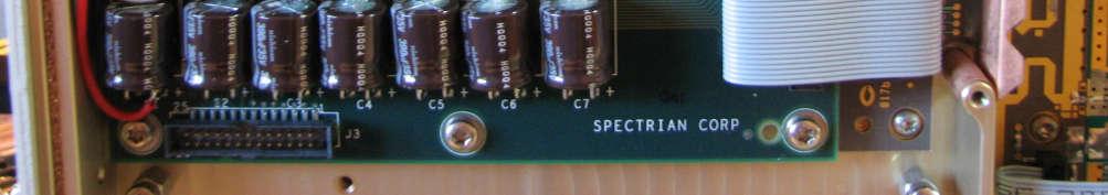
5 Enhancements (To be Completed) 2.1 Metering Add an LCD voltmeter to the front on a bracket. Include a toggle switch to select between Current and Temperature Current Sense voltage drop across the paralleled 0.01 ohm resistors Temperature Tap off one of the output stage temperature sense outputs preferably from the middle PA board as it s likely to be the hottest. 2.2 Fan Control (High speed when Tx or High Temp) Put a resistor in series with the fans to slow (and quieten) them. Use a comparator on the temperature sense line to short the resistor when temp rises beyond a threshold (50 deg?). Could also switch to high speed when Tx.
 to suitable points: DC ON the 28V supply ENABLE 12V PA activation voltage FAULT another comparator on the temperature line set to say 80 deg?? 2.4 Power Sensing The output combiner includes FWD and REV power monitoring.")
6 2.3 Front Panel Status LEDs Chop off the front corner of the control PCB containing the LED s (see lower picture on page 2). Include the mounting holes. Wire the LED s back (with appropriate dropper R s etc.) to suitable points: DC ON the 28V supply ENABLE 12V PA activation voltage FAULT another comparator on the temperature line set to say 80 deg?? 2.4 Power Sensing The output combiner includes FWD and REV power monitoring. additional circuitry, power metering could be added. With some There is also a 30dB sense output that comes out the front panel.
Quiz Buzzer. Build Instructions. Issue 1.2
 Build Instructions Issue 1.2 Build Instructions Before you put any components in the board or pick up the soldering iron, just take a look at the Printed Circuit Board (PCB). The components go in the side
Features. Description. Table of Contents
 Features Very low profile Very high efficiency (typically 90%) Single and dual output versions Input voltages from 24V to 110VDC nominal voltages from 5V to 48VDC -40 C to +71 C operation without de-rating
(2 DPDT 2 4 X
 Dynaco ST-120 with VTA driver board Kit instruction manual Triode/Pentode version Congratulations on your purchase of the Dynaco ST-120 with VTA driver board kit. Every effort has been made to give you
LED PICTURE FRAME KIT
 ESSENTIAL INFORMATION BUILD INSTRUCTIONS CHECKING YOUR PCB & FAULT-FINDING MECHANICAL DETAILS HOW THE KIT WORKS MAKE A DISPLAY OF YOUR MOST TREASURED PHOTOGRAPH WITH THIS LED PICTURE FRAME KIT Version
KORG KR-55. µsync installation guide version 1.0, 14 October
 KORG KR-55 µsync installation guide version 1.0, 14 October 2016 www.artefacts.nl Introduction The Korg KR-55 or KR-55b has no standard din sync input. Artefacts developed a piece of hardware to convert
mygrid Installation Notes
 mygrid Introduction mygrid kits provide an easy to install, compliant, Solar Hybrid (On-Grid) or Off-Grid battery system. These installation notes outline all the processes required to effectively install
Norcal Power/SWR Meter Assembly & Operating Manual. Revision 1D 10/15/2008
 Norcal Power/SWR Meter Assembly & Operating Manual Revision 1D 10/15/2008 Copyright 2008 NorCal QRP Club Page 1 of 21 Contents CONTENTS...2 INTRODUCTION...3 SPECIFICATIONS...3 ASSEMBLY...4 OPERATING GUIDE...15
DCX2496 Linear Power Supply mod by
 DCX2496 Linear Power Supply mod by Construction Guide Linear Power Supply for the DCX2496 Introduction. One of my more rewarding modifications to the DCX2496 was the replacement of the stock I/O board
Fitment Guide Volkswagen Golf GTI MK V1.0
 Fitment Guide Volkswagen Golf GTI MK6 2010 V1.0 www.ecliptech.com.au You need 3 wires to fit the Shift-I to the GTI. Power and Ground from the diagnostics port (near driver s side knee) and the RPM signal
How to fit the remote parking heater module
 How to fit the remote parking heater module The function of this project is to convert a standard fuel burning heater on the diesel models of the Rover 75 and MG ZT to a remote controlled parking heater.
ECO-6 & Installation Manual
 ECO-6 & Installation Manual For the SPA4-RFR Upgrade Kit To upgrade SPA4 amplifiers v1.00 & v1.01 to v2.0 Some sections also apply to the PA1, PA2, and PA3 14 August 2015 2015 by Ralph Hartwell Spectrotek
Professional Wireless Products
 Page 1 of 6 093115 Communications Power Supply and Battery Management Controller Page 2 of 6 1.0 Introduction The 093115 is a 13.8 volt 15amp transformer isolated switch mode down converter designed to
Modifications to the TS-930 Power Supply. Ken Grant, VE3FIT
 Modifications to the TS-930 Power Supply Ken Grant, VE3FIT My TS-930 has a serial number in the 5 million and uses a +21.7 Volt low-current regulator as well as the normal +28.5 V high current supply.
ELECTRIC SCHEMATICS LS1 LS2. "1532ES / 1932ES" Service & Parts Manual - ANSI Specifications March 2008 Page 5-9 ART_2236 ART_2243
 ELECTRIC SCHEMATICS NOTES: (Unless otherwise specified). Switch S BASE/PLATFORM makes contact from the CENTER to the LEFT position when placed in BASE.. Switch S UP/DOWN makes contact from the CENTER to
Harbach Soft Key (sk-220) Installation Instructions for the Heathkit SB-220
 Installation Instructions for the Heathkit SB-220") Harbach Soft Key (sk-220) Installation Instructions for the Heathkit SB-220 Step-by-Step Instructions with Photos Based on an install by W4HDM Installation & Photos by W4HDM Instructions from http://www.harbachelectronics.com/
Harbach Soft Key (sk-220) Installation Instructions for the Heathkit SB-220 Step-by-Step Instructions with Photos Based on an install by W4HDM Installation & Photos by W4HDM Instructions from http://www.harbachelectronics.com/
SYSTEM OPERATION IMPORTANT CAUTIONS
 SYSTEM OPERATION The system is turned on by placing the gear shift lever in the reverse position. The green light on the cab Control Box will illuminate to indicate the system is operating. When an object
Tip: 2856 LED Lighting for the Airport Express Set Date:
 Hi All, The 2856 Airport Express set was manufactured in 1983. On 09-11-1989 the locomotive was given a digital upgrade using a 6080 decoder. It has since had a digital upgrade to a high performance motor
FITTING OIL TEMP AND PRESSURE GUAGES
 FITTING OIL TEMP AND PRESSURE GUAGES this guide is of reference to fitting an oil temp and pressure sender/ sensor into a sandwich plate- not the sump plug temp sensor (although it wouldn't be much different
INSTALLATION AND SET-UP MANUAL FOR THE NEW: AVR-07. A CONTROLPAK AVR Automatic Voltage Regulator for three-phase and single-phase alternators
 INSTALLATION AND SET-UP MANUAL FOR THE NEW: AVR-07 A CONTROLPAK AVR Automatic Voltage Regulator for three-phase and single-phase alternators This is a premium quality product at a reasonable price, and
RDAC XG Engine monitoring module for MGL Avionics CAN bus compatible EFIS systems.
 RDAC XG Engine monitoring module for MGL Avionics CAN bus compatible EFIS systems. This Engine monitor is fully compatible with the larger RDAC XF device. Compared to the RDAC XF the following inputs are
Nistune Z32 ECU Modifications for R33 RB25DET Skyline Installation
 Nistune Z32 ECU Modifications for R33 RB25DET Skyline Installation Revision 10 26 May 2013 Thanks to Eric at DTA Motorsports and Andrew H for their help with previous versions. Many thanks and credits
Modifying the exterior lighting of the Ram truck
 Modifying the exterior lighting of the Ram truck The Ram truck has been designed and developed using standard incandescent lights. These lights are controlled by a computerized module called the Central
NOTE: CAPACITOR LEADS IN FIG #1 MAY REQUIRE SPLICING USING GA BUSS WIRE & SLEEVING AS NECESSARY TO ATTAIN REQUIRED LEAD LENGTH. 704
 DIGITAL READ OUT (2.70 IDEAL FOR THIS RESISTOR) ENGAGE DCVΩ BUTTON DIGITAL VOLT METER ZERO ADJUST-CONNECT (2) ALLIGATOR CLIPS TOGETHER & ADJUST UNTIL DIGITAL READ OUT IS 0.00 NOTE: THIS MUST BE REPEATED
Reversing Hand Throttle and Horn Relay Board RBT / HRB
 Instruction Manual Reversing Hand Throttle and Horn Relay Board RBT / HRB Contents Section Page Section Page 1. Introduction... 2 2. Do's and Don ts... 2 3. Horn Relay Board... 3 3.1 HRB Versions... 3
Modifying the exterior lighting of the Ram truck
 2013 Chassis Cab Exterior Lighting Modifications / LED Rear Lighting Modifying the exterior lighting of the Ram truck The Ram truck has been designed and developed using standard incandescent lights. These
Product Guide: Series III Pump Control Board Set (RoHS)
") revised 04/08/10 Description: The Series III Pump Control Board Set provides motor drive and pump control for a wide assortment of pumps from Scientific Systems, Inc. The assembly consists of two circuit
revised 04/08/10 Description: The Series III Pump Control Board Set provides motor drive and pump control for a wide assortment of pumps from Scientific Systems, Inc. The assembly consists of two circuit
Essential Electricity Homework Exercise 1
 Homework Exercise 1 1. For each of the following electrical symbols, copy the symbol into you jotter and label it using the words below. Word bank resistor, voltmeter, battery, ammeter, bulb V A 2. State
INSTALLATION INSTRUCTION
 INSTALLATION INSTRUCTION 0 F LOW AMBIENT ACCESSORY MODELS 2LA04703425, 3546 & 3658 (208, 230, 460 & 575 VOLT APPLICATIONS) Supersedes: 530.18-N5.6V (1091) 530.18-N5.6V (1193) FOR 15, 20 & 25 TON COOLING
Tri-Spark Ignition System Installation Triple Cylinder TRI-0001
 Tri-Spark Ignition System Installation Triple Cylinder TRI-0001 There are potentially lethal high voltages produced at the ignition coils and spark plugs, therefore every precaution must be taken to prevent
PPS20 COMMUNICATIONS POWER SUPPLY AND BATTERY MANAGEMENT SYSTEM
 PPS20 COMMUNICATIONS POWER SUPPLY AND BATTERY MANAGEMENT SYSTEM 2 Table of Contents Introduction:... 3 1.0: Operation Principles:... 3 1.1: Stand alone supply... 3 1.2: Backed up supply:... 3 1.3: Battery
200 Shadylane Drive Philipsburg, PA Phone: (814) Fax: (814) Service Manual
 Fax: (814) Service Manual") 200 Shadylane Drive Philipsburg, PA 16866 Phone: (814) 342-6205 Fax: (814) 342-4510 www.druckerdiagnostics.com Service Manual Model 755VES Centrifuge MODEL 755VES SERVICE MANUAL REV: A 1 CONTENTS 1 PREFACE...
200 Shadylane Drive Philipsburg, PA 16866 Phone: (814) 342-6205 Fax: (814) 342-4510 www.druckerdiagnostics.com Service Manual Model 755VES Centrifuge MODEL 755VES SERVICE MANUAL REV: A 1 CONTENTS 1 PREFACE...
BRKC-180. User s Manual and Installation Guide. Braking circuit. Contents. 1. Safety, policy and warranty.
 BRKC-180 Braking circuit User s Manual and Installation Guide Contents 1. Safety, policy and warranty. 1.1. Safety notes. 1.2. Policy. 1.3. Warranty. 2. Electric specifications. 2.1.Operation ranges. 3.
350 Watt Vacuum Tube Amplifier. Owner s Manual
 350 Watt Vacuum Tube Amplifier Owner s Manual CIRCUIT DESCRIPTION The input stage consists of a 12AX7 current sourced long-tailed balanced pair, which is direct coupled to a second long-tailed balanced
Installation Tips for your Crimestopper/ProStart Remote Start system (add-on for GM vehicles) v1.02 updated 1/16/2013
 v1.02 updated 1/16/2013") Installation Tips for your Crimestopper/ProStart Remote Start system (add-on for GM vehicles) v1.02 updated 1/16/2013 Thank you for purchasing your remote start from MyPushcart.com - an industry leader
Installation Tips for your Crimestopper/ProStart Remote Start system (add-on for GM vehicles) v1.02 updated 1/16/2013 Thank you for purchasing your remote start from MyPushcart.com - an industry leader
SFGH-100SC SIREN & LIGHT SYSTEM Installation & Operation
 SFGH-100SC SIREN & LIGHT SYSTEM Installation & Operation Rev.7/15 The SFGH-100SC is a precision built, full function 100-watt siren system that incorporates both an alternating headlight and brake light
HOW IS ELECTRICITY PRODUCED?
 ELECTRICITY HOW IS ELECTRICITY PRODUCED? All electricity is produced from other sources of energy. Hydroelectricity is produced from the stored energy of water held back by a dam. As the water runs downhill
elabtronics Voltage Switch
 elabtronics Voltage Switch Want to trigger a device when a monitored voltage, temperature or light intensity reaches a certain value? The elabtronics Voltage Switch is an incredibly easy way of doing it.
Table 1: 2-pin Terminal Block J1 Functional description of BSD-02LH Module Pin # Pin Description Table 2: 10-pin Header J2 Pin # Pin Description
 Functional description of BSD-02LH Module The BSD-02LH module is the part of the BSD-02 family of drivers. The main difference is higher microstepping resolution. The BSD-02LH is suitable for driving bipolar
10260 Retrofit to 10260A Non-Contact Sensor Instructions Kits through -512
 10260 Retrofit to 10260A Non-Contact Sensor Instructions Kits 51404974-501 through -512 Document Number Form: 62-86-33-16D Effective: 3-1-01 Supersedes: 11-00 Summary Retrofitting your 10260 actuator from
72 Mustang Mach 1 tachometer cluster and gauge conversion
 72 Mustang Mach 1 tachometer cluster and gauge conversion Dated: 02-17-2009 (drafted by a Chevy person working on his first Ford -not good-) Revised: 11-05-2010 The following information pertains to how
CARM INTERNATIONAL TOWING MODULES
 CARM INTERNATIONAL TOWING MODULES (TA100/200 Instructions Revision = 1) Each Towing Module (if ordered with Loom Pack) is shipped with: A/ These instructions B/ 1 x Towing Control Module C/ 1 x high current
INSTALLATION & OPERATING MANUAL RW SERIES WALL-MOUNT RECTIFIERS
 INSTALLATION & OPERATING MANUAL RW SERIES WALL-MOUNT RECTIFIERS WWW.UNIPOWERTELECOM.COM Manual No. RW-1 2008 UNIPOWER Corp. 01/24/08 rw-man All Rights Reserved UNIPOWER Telecom, Division of UNIPOWER Corporation
R Z18 Series : SMB CARLOCK
 .. pn ao TECHNICAL DATA SHEET 1 / 7 EDGE CARD PIN IN PASTE VERSION All dimensions are in mm. COMPONENTS MATERIALS PLATING (µm) BODY CENTER CONTACT OUTER CONTACT INSULATOR GASKET OTHERS PARTS ZINC ALLOY
7007 Loop Mate 2 Loop / Voltage / Current Simulator
 7007 Loop Mate 2 Loop / Voltage / Current Simulator User Manual Time Electronics Ltd Unit 11 Botany Industrial Estate Tonbridge, Kent, TN9 1RH Tel: 01732 355993 Fax: 01732 770312 E-Mail: mail@timeelectronics.co.uk
XLM 62V Energy Storage Module
 Technical Note 10406 XLM Energy Storage Module XLM 62V Energy Storage Module Introduction The XLM energy storage modules are self-contained energy storage devices comprised of twenty-three individual supercapacitor
1 T835 Installation. 1.2 Rack Wiring. 1.1 Rack Mounting
 M0-00 T Installation F. T Installation. Rack Mounting The T receiver is designed for use in a standard mm rack frame using a Tait T00 Series II guide. The guide is securely mounted to the rack frame with
My project: A prototyping test bed complete with 3.3, 5, and 12 volt power supplied, measuring tools, and breadboard.
 If you are like me and most other hobbyist, you have a huge box of goodies, those little things that are just too cool looking to through away and fully intend to someday use them. Well I finally decided
Installation Guide and User s Manual
 Installation Guide and User s Manual Version 1 Table of Contents 1. Introduction...1 1.1 Notes and warnings...1 2. Installation/Setup...2 2.1 LCD monitor...2 2.2 Monitor inputs...2 3. Monitor wiring harness...3
P1110-EVAL-PS. PowerSpot RF Wireless Power Development Kit for Battery Recharging. User Manual
 P1110-EVAL-PS PowerSpot RF Wireless Power Development Kit for Battery Recharging User Manual Overview The PowerSpot RF Wireless Power Development Kit for Battery Recharging is a complete demonstration
LV2000. revision 1.5. Low Voltage Power Supply Retrofit Kit for Wells-Gardner Color XY Monitor, model 19K6100. Installation Instructions ! WARNING!
 LV2000 revision 1.5 Low Voltage Power Supply Retrofit Kit for Wells-Gardner Color XY Monitor, model 19K6100 Installation Instructions! WARNING! To successfully install this kit requires that you have good
Mar H: SUPPLEMENTAL PARALLELING GEAR (16315-H)
") 2101 Commonwealth Blvd, Suite B Ann Arbor, MI 48105-5759 www.med.umich.edu/facilities/plan/ 263010-H: SUPPLEMENTAL PARALLELING GEAR (16315-H) Related Sections Basis Guideline: N/A For an explanation of
2101 Commonwealth Blvd, Suite B Ann Arbor, MI 48105-5759 www.med.umich.edu/facilities/plan/ 263010-H: SUPPLEMENTAL PARALLELING GEAR (16315-H) Related Sections Basis Guideline: N/A For an explanation of
Systems: Electronics
 Systems: Electronics Resistors & Capacitors Units for resistors and capacitors size/component small large resistance ohm kilohm megaohm capacitance picofarad microfarad farad current milliampere Ampere
USER MANUAL. Maxwell Technologies BOOSTCAP 56V UPS Energy Storage Modules. Models: BMOD0130 P056 B02 BMOD0130 P056 B03. Document Number
 USER MANUAL Maxwell Technologies BOOSTCAP 56V UPS Energy Storage Modules Models: BMOD0130 P056 B02 BMOD0130 P056 B03 Document Number 1017025 Notice: The products described herein are covered by one or
ASSEMBLY INSTRUCTIONS FOR NEW FK109 4 LED Railroad Crossing Flasher Kit WITH ADJUSTABLE FLASHING SPEED CONTROL with 4 Red 3mm Leds
 ASSEMBLY INSTRUCTIONS FOR NEW FK109 4 LED Railroad Crossing Flasher Kit WITH ADJUSTABLE FLASHING SPEED CONTROL with 4 Red 3mm Leds Description: Very easy to build, The FK109 Led Flasher kit makes the perfect
CENTROIDTM. AC Brushless Drive. Product Spec Sheet
 4 Axis, up to 2 KW motors Brake Output for each axis Overtemp and Overcurrent Protection All-software Configuration Self-cooled Fiber Optic Control CENTROIDTM AC Brushless Drive Product Spec Sheet AC Brushless
Cabin Light. Hi All, 1
 Hi All, My friend Rudolf set me a challenge for his 36331 electric locomotive, wanting Telex couplers fitted. When I opened up the locomotive I discovered there is very little room to add extra components
Battery Control Center - Diesel
 Service Manual CAUTION: All servicing of the Battery Control Center should be done only by a qualified Service Technician. Inadvertent shorts inside the Battery Control Center could result in severe damage
Electrical Circuits W.S.
 Electrical Circuits W.S. 1. In the circuit shown at the right, a voltage of 6 V pushes charge through a single resistor of 2 W. According to Ohm's law, the current in the resistor, and therefore in the
How I Fitted the Digital Temperature Guage... By T-Cut
 How I Fitted the Digital Temperature Guage... By T-Cut Here's one way to install the digital temperature gauge designed by Hans Schaaper. I decided to fit mine into the redundant slot above the CD-80 radio
User Manual. BMS123 Smart
 User Manual BMS123 Smart Introduction After the introduction of affordable LiFePO4 batteries, off-grid solutions became available for wide public. It is vital that such batteries are charged very carefully.
NEMA 1, NEMA 4X and Chassis Mount Adjustable Speed Controls for DC Motors
 Made in the U.S.A. NEMA 1, NEMA 4X and Chassis Mount Adjustable Speed Controls for DC Motors Nema Enclosed DC Control Specifications Catalog Number BC140 or Features BC138 BC139 BC140-FBR BC154 BC160 BCWD140
METROLOGIC INSTRUMENTS, INC. MX001 Industrial Control Interface Installation and User s Guide
 METROLOGIC INSTRUMENTS, INC. MX001 Industrial Control Interface Installation and User s Guide Copyright 2007 by Metrologic Instruments, Inc. All rights reserved. No part of this work may be reproduced,
Technology Advancements in Board Level Shields for EMI Mitigation
 Technology Advancements in Board Level Shields for EMI Mitigation Not Your Daddy s s Metal Can Gray Fenical inarte EMC and ESD Engineer APPROACH Fixing the CAUSE of the problem is usually always better
Ljunggren Audio Roll Your Own Penta
 Ljunggren Audio Roll Your Own Penta Version: Penta 1.0 Bills Of Material Bold = PCB1, The rest = PCB2 Type Parts Des cription Pow er header Qty Value 1 2x5pin POWER Euro pow er connector Jack 1 3.5mm J1,
Hasse Mods for the Ampeg J20 Guitar Amp
 Hasse Mods for the Ampeg J20 Guitar Amp The following is adapted from a post I put up on The Gear Page, in the Amp Techincal forum. It shows the mods I did to my Ampeg J20. Okay, here s my mods for this
Nistune Z32 ECU Modifications for R33 RB25DET Skyline Installation
 Nistune Z32 ECU Modifications for R33 RB25DET Skyline Installation Revision 8 10 July 2012 Thanks to Eric at DTA Motorsports, Skyline Stu and Andrew H for their help. Overview Fitting of the Z32 ECU is
Science Olympiad Shock Value ~ Basic Circuits and Schematics
 Science Olympiad Shock Value ~ Basic Circuits and Schematics Use a single D battery, a single bare wire and a light bulb. Find four different ways to light the light bulb using only a battery, one wire
J1 Plug Pin Identification
 D5 D D D D5 D ART_ J D D0 R R R R TB 0 D D D D D D J Plug Pin Identification PIN # WIRE # SIGNAL FUNCTION 0 INPUT Drive Reverse INPUT Drive Forward OUTPUT Brake, Decel Valve signal INPUT Steer Left 5 OUTPUT
2005 and 09 Mustang install instructions Sequential / Chase Unit Partial Plug-N-Play Kit Meter4it Eng. Updated: 3/28/09
 Updated: 3/28/09 Verify content of kit: 1- Unit with wiring harness 1- Red power wire with 15 amp fuse 1- Color instruction 2- Velcro for mounting 1-Driver taillight harness 1- Passenger taillight harness
J1 Plug Pin Identification
 D D8 D D D D ART_8 J 8 D D0 R R R R TB 80 D D D D D D J Plug Pin Identification PIN # WIRE # SIGNAL FUNCTION 0 INPUT Drive Reverse INPUT Drive Forward OUTPUT Brake, Decel Valve signal 8 INPUT Steer Left
Wiring Harness 1. Remove left hand footwell trim panel from driver s footwell. Typically secured by several Philips head screws.
 Installation There are four segments to the installation; wiring harness, EDIS and Megajolt, coil pack, and Timing wheel and VR sensor. If the car needs to be driven, install everything except the coil
J1 Plug Pin Identification
 D5 D8 D7 D4 D5 D ART_8 J 4 8 D D0 7 R R R R4 TB 80 D D D D4 D D J Plug Pin Identification PIN # WIRE # SIGNAL FUNCTION 0 INPUT Drive Reverse INPUT Drive Forward OUTPUT Brake, Decel Valve signal 4 8 INPUT
QRPGuys Digital RF Probe
 QRPGuys Digital RF Probe First, familiarize yourself with the parts and check for all the components. If a part is missing, please contact us and we will send one. This kit contains seventeen 1206 size
Soldering Pi2Go Lite. Soldering the Line-Follower PCB
 Soldering Pi2Go Lite First check which version of the main PCB you have. It is marked above the left motor "Pi2Go-Lite v1.x". There are minor changes to some parts of the build. v1.0 (initial release)
R-1125 C HARNESS MOUNT BAR INSTALLATION INSTRUCTIONS Fits C7 Corvette Coupes, including Z06
 R-1125 C HARNESS MOUNT BAR INSTALLATION INSTRUCTIONS Fits C7 Corvette Coupes, including Z06 The R-1125 Harness Mount Bar has been designed and tested to provide a mounting point for the shoulder harness
Foreword and disclaimer:
 Installation guide for the ADA Depot MDRT transformer. Foreword and disclaimer: Thank you for purchasing this Machinator transformer kit. These kit suites the MP-1,/ MB-1. This kit also solves the famous
Application Note. Bachmann F40PH Tsunami Digital Sound Decoder Installation Notes
 Application Note Bachmann F40PH Tsunami Digital Sound Decoder Installation Notes Overview This application note describes how to install a TSU-AT1000 Digital Sound Decoder into a Bachmann HO F40PH. Skill
Lithium Ion Battery Charger for Solar-Powered Systems
 Lithium Ion Battery Charger for Solar-Powered Systems General Description: The is a complete constant-current /constant voltage linear charger for single cell Li-ion and Li Polymer rechargeable batteries.
Yaskawa Electric America Unit Troubleshooting Manual Section One: Introduction & Checks Without Power GPD 506/P5 and GPD 515/G5 (0.
 Yaskawa Electric America Unit Troubleshooting Manual Section One: Introduction & Checks Without Power GPD 506/P5 and GPD 515/G5 (0.4 ~ 160kW) Page 1 Introduction This manual is divided into three sections:
ez1081pre Mic Amplifier - Assembly manual [ Colourbook Issue 1]
![ez1081pre Mic Amplifier - Assembly manual [ Colourbook Issue 1]](/thumbs/90/103906919.jpg "ez1081pre Mic Amplifier - Assembly manual [ Colourbook Issue 1]") ez1081pre Mic Amplifier - Assembly manual [ Colourbook Issue 1] ez1081pre Colourbook Contents. Section 1 - Colourbook assembly guide Section 2 - Setup and Calibration Section 3 - Schematics diagrams and
ez1081pre Mic Amplifier - Assembly manual [ Colourbook Issue 1] ez1081pre Colourbook Contents. Section 1 - Colourbook assembly guide Section 2 - Setup and Calibration Section 3 - Schematics diagrams and
Electrical Circuits Discussion Questions:
 Electrical Circuits Discussion Questions: 1) What is electricity? 2) How does an electrical circuit work? 3) What types of materials conduct electrical energy? 4) How is electrical energy measured? 5)
Hiding a Ford Regulator in an Alternator Equipped Citroen D s and SM s By Mark L. Bardenwerper, Sr. January 3, 2007
 Hiding a Ford Regulator in an Alternator Equipped Citroen D s and SM s By Mark L. Bardenwerper, Sr. January 3, 2007 Many of us have replaced the Ducellier voltage regulators on our alternator equipped
AIRSTREAM - BATTERY CONTROL CENTER - Diesel
 P/N 00-00755-000 CAUTION: The Battery Control Center is a centralized power switching, fusing, and distribution center. Power from both the chassis and coach batteries is fed into the box. The full power
The N4YG DDS VFO and the Drake TR7
 The N4YG DDS VFO and the Drake TR7 Overview This document describes the installation of a N4YG DDS VFO into my Drake TR7 transceiver. The VFO is a terrific improvement over the original PTO and adds function
Lycoming Engine Sender Installation Guide
 3401 Airport Drive Ste E, Torrance, CA 90505. Tel: 1-877-8FLYING Fax: 1-310-534-2282 e-mail: sales@mglavionics.com Web: www.mglavionics.com MGL Avionics EFIS Lycoming Engine Sender Installation Guide This
1. Replace the plugs with the cheap Autolite (25) copper-core plugs, set to 80 thou gap.
 copper-core plugs, set to 80 thou gap.") A recently encountered e-mail from Robert Calloway states that Tesla s bi-filar series-connected coil is effective in picking up radiant energy. In the light of that, and in the absence of further information
A recently encountered e-mail from Robert Calloway states that Tesla s bi-filar series-connected coil is effective in picking up radiant energy. In the light of that, and in the absence of further information
Guide to Installing Your Summit Stairway Lift
 Guide to Installing Your Summit Stairway Lift 2 3 W E L C O M E O H E S U M M I F A M I L Y B E F O R E Y O U S A R Congratulations on your purchase of a Summit Stairway Lift. hese instructions will assist
Chevy Sonic 2012-up G
 INSTALLATION INSTRUCTIONS FOR PART 99-3012 APPLICATIONS Chevy Sonic 2012-up 99-3012G KIT FEATURES ISO DIN Head unit provision with pocket DDIN Head unit provisions Painted Gray to match factory finish
MODEL 2202 ( MSRP $549.00)
") F O R T H E L O V E O F M U S I C MODEL 2202 (1989 - MSRP $549.00) OWNER S OPERATION MANUAL AND INSTALLATION GUIDE INTRODUCTION Power Supply: Self oscillating for reliability and efficiency. The transformer
F O R T H E L O V E O F M U S I C MODEL 2202 (1989 - MSRP $549.00) OWNER S OPERATION MANUAL AND INSTALLATION GUIDE INTRODUCTION Power Supply: Self oscillating for reliability and efficiency. The transformer
XENON POWER SUPPLY Compact Model 220 Volt Equipment Type
 XENON POWER SUPPLY Compact Model 220 Volt Equipment Type 62-80106 62-80108 62-80109 62-80113 Rev. August 2001 STRONG INTERNATIONAL a division of Ballantyne of Omaha, Inc. 4350 McKinley Street Omaha, Nebraska
BMS S63TU Stage1 and JB4 Install Guide
 BMS S63TU Stage1 and JB4 Install Guide Last updated 3/23/2018 Use subject to terms and conditions posted at http://www.burgertuning.com/terms.htm THIS PART IS LEGAL FOR USE ONLY IN COMPETITION RACING VEHICLES
470nF REG1 LM2940. VR3 100k 10k VR1 100 F. 470pF. 100nF. 100nF RELUCTOR Q2 BC k. 10k TP GND. 2.2nF TO RELUCTOR. 470nF REG1 LM2940 REG1 LM2940
 Where to buy kits Jaycar and Altronics have full kits (including the case) available for the High Energy Electronic Ignition System. The Jaycar kit is Cat. KC-5513 while the Altronics kit is Cat. K4030
Simple Free-Energy Devices
 Simple Free-Energy Devices This presentation is mainly for people who have never come across free-energy and know nothing about it. So, each chapter deals with just one device and tries to explain it clearly.
K Wiring and Electronics
 HKBay.com K Wiring and Electronics Written By: HKBay 2017 hkbay.dozuki.com Page 1 of 12 TOOLS: Hex key; ball ended, long arm, 2.5mm (1) PARTS: Arduino Mega (blue) (1) RAMPS board (red) (1) glass tabs (3)
XLR Energy Storage Module
 Technical Note 19 XLR Energy Storage Module XLR Energy Storage Module Safety The XLR 48 V module contains stored energy of 54 watt-hours and can discharge up to 97 amps if short circuited. Only personnel
Focus ST Carbon Fiber Intake
 791400 - Focus ST Carbon Fiber Intake 791400 COBB Focus ST Carbon Fiber Intake Congratulations on your purchase of the COBB Tuning Carbon Fiber Intake System! The following instructions will assist you
ELECTRICAL SYSTEM RP-7
 ELECTRICAL SYSTEM RP-7 This section of the manual does not include integral electrical components of the engine. Refer to section Engine RP-1 for details. This section of the manual is divided into three
User Manual JS-ICON. 624 ARCH Dimmer Rack. JOHNSON SYSTEMS INC. Spring
 User Manual JS-ICON 624 ARCH Dimmer Rack JOHNSON SYSTEMS INC. Spring 2007 2002161 Table of Contents JS-ICON 624 DMX JS-ICON 624 CC 6-2.4kW Dimming Strip JS-ICON 624 ND 6-2.4kW Relay Strip Introduction...3
CHAPTER 2. Current and Voltage
 CHAPTER 2 Current and Voltage The primary objective of this laboratory exercise is to familiarize the reader with two common laboratory instruments that will be used throughout the rest of this text. In
Aluminium Profile Catalog Version 1.0 English
 Aluminium Profile Catalog - 2008 Version 1.0 English Product Range Aluminium Profile and Accessories - Extruded aluminium profiles - Joining elements - Levelling feet - End covers and slot covers Assembly