surge arresters overvoltage limiters Low voltage limiters catalogue 2017
|
|
|
- Shauna Price
- 5 years ago
- Views:
Transcription
1 catalogue 2017 surge arresters overvoltage limiters Low voltage limiters
2 CONTENT OF THE CATALOGUE COMPANY PROFILE ACER VOLTAGE 2 OVERVOLTAGE DEFINITIONS, OVERVOLTAGE LIMITERS ZnO 3 DIMENSIONING OF OVERVOLTAGE LIMITERS 4 CONNECTING OF THE OVERVOLTAGE LIMITERS, THEIR MAINTENANCE AND CONTROL 5 OVERVOLTAGE LIMITERS, AC NETWORK, SERIES PSP */5 ka - DISCHARGE CLASS 1 Indoor and outdoor use 6 OVERVOLTAGE LIMITERS, AC NETWORK, SERIES PSP */10 ka - DISCHARGE CLASS 1 Indoor and outdoor use 7 OVERVOLTAGE LIMITERS, AC NETWORK, SERIES PSP */10/III - DISCHARGE CLASS 3 Indoor and outdoor use 8 OVERVOLTAGE LIMITERS, AC NETWORK, SERIES PSPI */10/III - DISCHARGE CLASS 3 Indoor use 9 OVERVOLTAGE LIMITERS, AC NETWORK, SERIES PSP */20/IV - DISCHARGE CLASS 4 Indoor and outdoor use 10 OVERVOLTAGE LIMITERS, AC NETWORK, SERIES PSPI */20/IV - DISCHARGE CLASS 4 Indoor use 11 OVERVOLTAGE LIMITERS, AC NETWORK, SERIES PSP */20/V - DISCHARGE CLASS 5 Indoor and outdoor use 12 OVERVOLTAGE LIMITERS, AC NETWORK, SERIES PSPI */20/V - DISCHARGE CLASS 5 Indoor use 13 OVERVOLTAGE LIMITERS, DC NETWORK, SERIES PSP */10/III - DISCHARGE CLASS 3 Indoor and outdoor use 14 OVERVOLTAGE LIMITERS, DC NETWORK, SERIES PSPI */10/III - DISCHARGE CLASS 3 Indoor use 15 OVERVOLTAGE LIMITERS, DC NETWORK, SERIES PSP */20/IV - DISCHARGE CLASS 4 Indoor and outdoor use 16 OVERVOLTAGE LIMITERS, DC NETWORK, SERIES PSPI */20/IV - DISCHARGE CLASS 4 Indoor use 17 OVERVOLTAGE LIMITERS, AC NETWORK, SERIES PSPI */10 - DISCHARGE CLASS 1 Indoor use 18 OVERVOLTAGE LIMITERS, AC NETWORK, SERIES PSPN */10/III - DISCHARGE CLASS 3 Indoor use 19 UNIVERSAL SURGE ARRESTER AC NETWORKS SERIES SPDxxx, SPDxxxS and SPDxxxFM TYPE 2 + TYPE 3 Indoor use 20 SPDxxx, SPDxxxS and SPDxxxFM, SUMMARY OF PRODUCED TYPES 21 - AC NETWORK U N = VAC P60G AND P120G, LOW VOLTAGE LIMITERS FOR RAILWAY APPLICATIONS Indoor and outdoor use 22 P400G AND P250G, LOW VOLTAGE LIMITERS FOR RAILWAY APPLICATIONS Indoor and outdoor use 23 P600G, POWER GAS DISGARGE TUBES FOR POTENTIAL EQUALISATION 24 ON METAL PARTS OF INDUSTRIAL TECHNOLOGY Indoor and outdoor use P60GI AND P120GI, LOW VOLTAGE LIMITERS FOR RAILWAY APPLICATIONS Indoor use 25 P400GI AND P250GI, LOW VOLTAGE LIMITERS FOR RAILWAY APPLICATIONS Indoor use 26 P600GI, POWER GAS DISGARGE TUBES FOR POTENTIAL EQUALISATION 27 ON METAL PARTS OF INDUSTRIAL TECHNOLOGY Indoor use SURGE ARRESTERS SPB */10 PP ON FLAT BUSBARS Indoor AND OUTDOOR use 28 SURGE ARRESTERS SPB */10 AlFe ON BARE OVERHEAD CONDUCTORS Indoor AND OUTDOOR use 29 SURGE ARRESTERS SPB */10 S ON INSULATED OVERHEAD CONDUCTORS Indoor AND OUTDOOR use 30 CHARACTERISTICS AND PERRORMANCE OF SURGE ARRESTERS SPB */10 31 G-TESTER 32 Simple portable diagnostic device designed for quick control of surge protection devices (SPD) containing metal oxide varistors and gas-filled surge arresters (GDT) REFERENCE, PHOTOS 33 NOTES 34 Page 1

3 A satisfied customer is our aim at all times Professional surge arresters and overvoltage limiters Protection of the power supply of trolley lines, distribution transformers and LV electrical equipment in AC networks... Applications for transport companies and railways Protection of converter stations and DC networks of electric traction systems linked to them, electrical equipment of trolleybuses, trams and electric locomotives... Protection against atmospheric and switching overvoltage Protection of HV transmission networks, transformers, switchgear and HV cable distribution systems... COMPANY PROFILE ACER VOLTAGE Ltd. was founded in 1992 in Hradec Kralove, originally called ACER. It is a purely Czech company which is engaged in the development and production of surge arresters and overvoltage limiters for the protection of LV and HV power distribution networks and protect equipment against lightning and switching overvoltage. Furthemore, it also focuses on the production of composite insulators. Products of ACER VOLTAGE company protects of its customers equipment from the devastating effects of the surge. This company acted since 2006 under the name ACER HK Ltd. and in the end 2014 moved into a new place of work, where it remains. In 2016, the company renamed to its current name ACER VOLTAGE Ltd. that better reflects its focus and activities. In the past, the company developed and manufactured varistors based on ZnO surge arresters in the LV applications and then another surge arresters made from them. The first type was a surge arrester SP / 10, which has been improved and is now produced only in design SPB * / 10 in various voltage levels acc. to type of installation. Production of ZnO varistors was abolished in 2006, and for current and surge arresters are only used varistors from external suppliers. Another significant part of production program are polymeric arresters for HV networks of 1-39 kv for AC or DC networks. They consist of the entire model range, which is constantly expanding. In addition, it is possible to produce nonstandard types according to customer requirements and specifications. Details about today s sortiment ACER VOLTAGE can be found at our catalog or website. Recently was expanded assortment of products with gas-filled power arresters. The Company has acquired and regularly renews certification according to DIN EN ISO 9001 certified. ACER VOLTAGE is a leading company supplying technology for power and automation that enable energy and industry could increase its efficiency while reducing their impact on the environment. ACER VOLTAGE products are delivered to 42 countries and are always close to its customers. With superior technology, global scale, deep industry expertise and local knowledge, we can offer our customers products, system solutions and services that help improve the reliability of their transmission networks. Due to focus and strengths in technologies for power and automation, we strive for organic growth. Our global manufacturing base ensures consistent products and systems of the highest quality produced in the ACER VOLTAGE for customers worldwide. Our customers have easy access to a full range of products, either directly with us as the manufacturer, or through a network of distributors or wholesalers, which is constantly expanding.to ensure the quality of products the company ACER VOLTAGE performs 100% inspection at production testing equipment. With these devices are controlled precise technical specifications throughout the production company ACER VOLTAGE. 2
4 Overvoltage definition Definition of overvoltage Overvoltage is voltage that exceeds the maximum value of operating voltage in an electric circuit. Pulse overvoltage, its formation and division Pulse overvoltage is short-term overvoltage, lasting in the order of nanoseconds up to milliseconds. It is one of the most noticeable and most harmful manifestations of electromagnetic interference (perturbing influences) and it poses a threat especially to electronic equipment containing semiconductor components. According to its origin, pulse overvoltage is classified into: - atmospheric overvoltage (LEMP Lighting ElektroMagnetic Pulse) - switching overvoltage (SEMP Switching ElektroMagnetic Pulse) - overvoltage formed during discharges of static electricity (ESD ElektroStatic Discharge) - overvoltage due to nuclear explosions (NEMP Nuclear ElektroMagnetic Pulse) Atmospheric overvoltage (LEMP) The most dangerous overvoltage which is induced primarily by thunderstorms with lightning discharges. Overvoltage may occur between a phase and the earth or between phase conductors. It is caused primarily by thunderstorm activity, specifically by lightning discharges, namely to overhead lines and in sections of unshilded cables. Atmospheric overvoltage may be generated by a direct or near strike of lightning into a overhead line, lightning rod, some metal structure, cable, etc. The destructive effect of lightning current is given by its high energy released in a short time, which creates conditions for inducing stress in loops accompanied by adverse changes of earth resistance. Switching overvoltage (SEMP) They are very frequent overvoltage that occurs in both low-voltage and high-voltage networks. Switching overvoltage is generated by industrial activities: - when great loads, especially inductive ones, are switched on and off, e.g. transformers or electric motors or even small household appliances, e.g. refrigerators, freezers - in the event of short circuits in a distribution network and the like. Invisible voltage pulses that are immeasurable by usual means last only several millionths or thousandths of a second, yet they can cause the destruction mainly of electronic equipment, sometimes even a short circuit and subsequent fire. ZnO overvoltage limiters Currently for the construction of surge arresters are usually used voltage dependent resistors with metal-oxide ZnO varistors, which excel symmetrical currentvoltage characteristics and a zero followed current after shock subside the surge.these basic properties allow the use of these resistors as ZnO surge limiters (arresters) without spark gaps. The parameters on the basis of which we design the limiters are as follows: - Continuous operating voltage of the limiter U C it represents the maximum value of voltage connected permanently to limiter terminals at mains frequency. - Rated voltage of the limiter U R it represents the maximum effective value of voltage for which the limiter is designed while the correct function under conditions of temporary overvoltage at mains frequency is maintained. Such voltage is defined as voltage to which the limiter is exposed for 10 seconds following previous stress. - Protective level of the limiter U P is voltage on terminals at a given shape and peak value of current passing though. - Nominal discharge current I n the peak value of an atmospheric current pulse that is used for the classification of overvoltage limiters. - Residual voltage U RES it represents residual voltage on the overvoltage limiter. It is actually the peak value of voltage that appears between terminals of the overvoltage limiter when discharge current is passing through it. - Working temperature J it represents the range of permissible ambient temperatures stated by the manufacturer for the limiter to work properly. - Line discharge class a number expressing the ability of the overvoltage limiter to absorb energy in the event that long lines are discharged. Overvoltage resistance of ZnO limiters By the magnitude of permissible energy, the overvoltage limiters are divided into five classes. The higher the class, the higher is the energy capacity of the limiter. The energy that the limiter has to absorb during overvoltage rises with the voltage of the network in which it is used. Voltage rises slower than energy. Limiters in networks with higher voltage must have a greater energy capacity than limiters in networks with lower voltage. The selection of the energy class and of the rated discharge current is based on the frequency at which the energy capacity is exceeded in the given application. An energy class expresses the ability of the limiter to absorb both atmospheric and switching overvoltage. It is stated in the units kj/kv of the limiter s voltage and is independent of nominal voltage. Energy classes 1 to 5 divide the limiters into groups according to the magnitude of the permissible energy of overvoltage that they are able to absorb without being degraded or without losing heat stability at operating voltage. The higher the class, the greater is the energy capacity of the limiter. The energy classes and an example of their use Class 1 use in HV networks without classification of class (5kA) or class 1 or 2 (10 ka) Class 2 use in 110 kv networks Class 3 use for kv networks and for cable networks Class kv long network lines Class 5 extremely extensive 750 kv cable networks 3
5 Dimensioning of the overvoltage limiters Dimensioning of the overvoltage limiters The overvoltage limiters are sized based on a particular position in the network, i.e. whether they are to protect e.g. a line outlet, a line transition into a cable or transformer. Whatever their position, they have specific conditions for protection and overvoltage stress. The design of these protective equipments for given application always project-designer decides. Selecting the operating voltage U C of limiters The operating voltage, voltage-current characteristics and all voltage parameters of the limiter are dependent upon the height of column of blocks. By contrast, all voltage parameters are set by the selection of operating voltage U C. Incorrect selection of voltage U C may have a considerably negative effect on the limiter s function. If a low U C is selected, the protective level U RES and also the risk of failure of the protected device associated with it will be favourably low. On the other hand, however, there will be a risk of thermal stress on the limiters caused by temporary overvoltage, so the probability of them failing will be high. If a high U C is selected, the risk of failure of the limiters owing to temporary overvoltage will be insignificant but a high protective level U RES will imply a higher probability of the protected devices being destroyed. The correct selection of continuous voltage U C of the limiters should mean optimum parameters of protection, hence a balanced risk of reliability of the supply for both causes. The protection parameters can be improved by connecting the limiters as close to the protected device as possible with as short interconnecting wires as possible! The limiters limit voltage to a limiter s protective level U P. A limiter s protective level U P is voltage on terminals with a given shape and peak value of current passing through. Values characterising a limiter s protective level can be found in our catalogue. It is a limiter s residual voltage U RES. Characteristics of overvoltage protection of LV and HV networks In LV and HV distribution networks with overhead lines, it is necessary to protect equipment primarily from atmospheric overvoltage. Switching overvoltage reaches substantially lower current and voltage levels than atmospheric. The greatest overvoltage in cable networks without connected overhead lines is caused by short circuits and/or switching. The primary task of protective measures which are economically fully justified is to protect the equipment of LV networks from destruction by atmospheric overvoltage by installing surge arresters and, at the same time, to enable the protection of installation by adequately reducing overvoltage in the network. Principles for positioning and wiring in low voltage networks Overvoltage limiters or surge arresters can be used in 1-phase and 3-phase networks TNC, TNS, IT and TT. typically, their connections is recommended to make between phase and grounding conductor E (or PEN with TNC networks in place of his ground). In the event that the grounding conductor is not accessible, it is necessary to use a suitable grounding electrode rod with a length at least 1 m. When designing and implementing of grounding is recommend to proceed according to PNE and PNE Generally applicable rules for connecting of overvoltage limiters 1) The overvoltage limiters and the device that is to be protected must be earthed to a common earthing system. The galvanic interconnection between the earthing terminals of the limiters and the earthing of the protected device must be as short as possible. 2) The total length of conductors a and b of connection of the limiters to the protected device must be as short as possible. 3) It is always recommended that conductor b should be as short as possible or at least shorter than conductor a. 4) Strip conductors are more suitable for connection than those with circular cross-section as with the same cross-section, becase strip conductors have smaller inductance and pulse losses of overvoltage in them are smaller. The minimum size of a connecting conductor is 6 mm. The minimum width of a strip conductor is 12 mm 2. Above all, the installation of overvoltage limiters in every application is prevention of possible damage. A seemingly considerable cost of such protections tend to be only a fraction of a per cent of the acquisition value of the technology protected and a negligible sum for possible damage caused by breakdowns and destruction of technological equipment. Unprotected electric distribution systems, computer and data networks always poses a considerable risk to their users. One-line diagram of protection with the marking of sections of conductor a and conductor b overvoltage wave 4
6 Connection of the limiters to the transformer Definition of overvoltage overvoltage limiter Transformer 110/22 kv grounding network Ground plan of the earthing network of limiters at the transformer limiters Transformer Connection of the limiter: (a) correct connection, (b) incorrect connection Maintenance and inspection of overvoltage limiters Complexly recommendations for maintenance and inspection of overvoltage limiters ZnO are specified in EN , where such control is divided into visual inspection.alternatively complete revision include important electrical measurements. Especially this control is recommended to make: - After any changes in protective elements belonging to the system installation - Periodically, at least 1 year - After direct strike to the protected instalation 5

7 PSP */5kA - OVERVOLTAGE LIMITER - LINE DISCHARGE CLASS 1 The limiters are suitable for both outdoor and indoor use OVERVOLTAGE LIMITER PSP */5kA LINE DISCHARGE CLASS 1 AC NETWORKS PSP */5kA - OVERVOLTAGE LIMITER - LINE DISCHARGE CLASS 1 Protection of high-voltage AC networks against lightning and switching surges and fast transients. Suitable for protection of transformers, cables, motors, switchgears, and other high-voltage equipment. PSP */5kA energy class 1 overvoltage limiters designed for protecting of high-voltage transmission networks; transformers, switchgears and HV cable distribution systems against of atmospheric and switching overvoltage effects. The functional part of the limiters consists a column of varistors sized for max. continuous operating voltage U C, the outer insulating shell is made from silicon material (grey colour). The material of the shell shows high resistance to the effects of surface leakage currents and to electric arc, possesses hydrophobic properties and shows excellent resistance to weather effects, pollution and UV radiation. The cover caps, connecting screws, nuts and terminals are made of stainless steel. With their design and technical parameters, the overvoltage limiters of the PSP series conform to the standards ČSN EN and IEC Technical data PSP 7/5 PSP 10/5 PSP 12/5 PSP 14/5 PSP 17/5 PSP 22/5 PSP 24/5 PSP 25/5 PSP 30/5 PSP 32/5 PSP 36/5 PSP 39/5 Max. continuous operating voltage U c 7 kv 10 kv 12 kv 14,5 kv 17 kv 22 kv 24 kv 25 kv 29 kv 32 kv 36 kv 39 kv Nominal voltage U r 9 kv 12 kv 15 kv 18 kv 21 kv 27 kv 30 kv 30 kv 36 kv 39 kv 45 kv 48 kv Nominal discharge current I n 5 ka 5 ka 5 ka 5 ka 5 ka 5 ka 5 ka 5 ka 5 ka 10 ka 5 ka 5 ka High impulze current (4/10) 2x65 ka 2x65 ka 2x65 ka 2x65 ka 2x65 ka 2x65 ka 2x65 ka 2x65 ka 2x65 ka 2x65 ka 2x65 ka 2x65 ka Long current impulse (2ms) 150 A 150 A 150 A 150 A 150 A 150 A 150 A 150 A 150 A 150 A 150 A 150 A Discharge class acc. to EN Residual voltage at In U res 27 kv 35 kv 45 kv 52,2 kv 62 kv 79 kv 88 kv 88 kv 108 kv 117 kv 131 kv 140 kv Height h 135 mm 157 mm 175 mm 196 mm 220 mm 262 mm 280 mm 280 mm 325 mm 340 mm 380 mm 400 mm Operating temperature range -40 C + 55 C Protection type IP65 Weight m 0,9 kg 1 kg 1,1 kg 1,3 kg 1,4 kg 1,7 kg 1,9 kg 1,9 kg 2,15 kg 2,3 kg 2,5 kg 2,7 kg Article number Note: The height and weight are indicative only and may vary. We can send accurate dat. Transport and storage The overvoltage limiters may not be exposed to strong shocks and impacts during transport. They should be stored in the long term in an indoor store. Maintenance No testing of the function or maintenance such as cleaning is necessary during the anticipated life of the limiter. 6


8 PSP */10kA - OVERVOLTAGE LIMITER - LINE DISCHARGE CLASS 1 The limiters are suitable for both outdoor and indoor use OVERVOLTAGE LIMITER PSP */10kA LINE DISCHARGE CLASS 1 AC NETWORKS 110 PSP */10kA - OVERVOLTAGE LIMITER - LINE DISCHARGE CLASS 1 Protection of high-voltage AC networks against lightning and switching surges and fast transients. Suitable for protection of transformers, cables, motors, switchgears, and other high-voltage equipment. PSP */10kA energy class 1 overvoltage limiters designed for protecting of high-voltage transmission networks; transformers, switchgears and HV cable distribution systems against of atmospheric and switching overvoltage effects. The functional part of the limiters consists a column of varistors sized for max. continuous operating voltage U C, the outer insulating shell is made from silicon material (grey colour). The material of the shell shows high resistance to the effects of surface leakage currents and to electric arc, possesses hydrophobic properties and shows excellent resistance to weather effects, pollution and UV radiation. The cover caps, connecting screws, nuts and terminals are made of stainless steel. With their design and technical parameters, the overvoltage limiters of the PSP series conform to the standards ČSN EN and IEC Technical data PSP 7/10 PSP 10/10 PSP 12/10 PSP 14/10 PSP 17/10 PSP 22/10 PSP 24/10 PSP 25/10 PSP 30/10 PSP 32/10 PSP 36/10 PSP 39/10 Max. continuous operating voltage (AC) U C 7 kv 10 kv 12 kv 14 kv 17 kv 22 kv 24 kv 25 kv 29 kv 32 kv 36 kv 39 kv Nominal voltage (AC) U r 9 kv 12 kv 15kV 18 kv 21kV 27 kv 30 kv 30 kv 36 kv 39 kv 45 kv 48 kv Nominal discharge current I n 10 ka 10 ka 10 ka 10 ka 10 ka 10 ka 10 ka 10 ka 10 ka 10 ka 10 ka 10 ka High impulze current (4/10) 2 x 100 ka 2 x 100 ka 2 x 100 ka 2 x 100 ka 2 x 100 ka 2 x 100 ka 2 x 100 ka 2 x 100 ka 2 x 100 ka 2 x 100 ka 2 x 100 ka 2 x 100 ka Long current impulse (2ms) 400 A 400 A 400 A 400 A 400 A 400 A 400 A 400 A 400 A 400 A 400 A 400 A Discharge class acc. to EN Residual voltage at I n U res 27 kv 36 kv 45 kv 54 kv 63 kv 81 kv 90 kv 90 kv 108 kv 117 kv 135 kv 144 kv Height h 135 mm 154 mm 175 mm 190 mm 220 mm 253 mm 280 mm 280 mm 313 mm 335 mm 380 mm 400 mm Operating temperature range -40 C + 55 C Protection type IP65 Weight m 1,3 kg 1,45 kg 1,7 kg 1,9 kg 2,2 kg 2,6 kg 2,8 kg 2,8 kg 3,2 kg 3,45 kg 3,9 kg 4,2 kg Article number Note: The height and weight are indicative only and may vary. We can send accurate dat. Transport and storage The overvoltage limiters may not be exposed to strong shocks and impacts during transport. They should be stored in the long term in an indoor store. Maintenance No testing of the function or maintenance such as cleaning is necessary during the anticipated life of the limiter. 7
9 PSP */10/III - OVERVOLTAGE LIMITER - LINE DISCHARGE CLASS 3 The limiters are suitable for both outdoor and indoor use OVERVOLTAGE LIMITER PSP */10/III LINE DISCHARGE CLASS 3 AC NETWORKS 180 PSP */10/III - OVERVOLTAGE LIMITER - LINE DISCHARGE CLASS 3 Protection of high-voltage AC networks against lightning and switching surges and fast transients. Suitable for protection of transformers, cables, motors, switchgears, and other high-voltage equipment. PSP */10/III energy class 3 overvoltage limiters designed for protecting of high-voltage transmission networks; transformers, switchgears and HV cable distribution systems against of atmospheric and switching overvoltage effects. The functional part of the limiters consists a column of varistors sized for max. continuous operating voltage U C, the outer insulating shell is made from silicon material (grey colour). The material of the shell shows high resistance to the effects of surface leakage currents and to electric arc, possesses hydrophobic properties and shows excellent resistance to weather effects, pollution and UV radiation. The cover caps, connecting screws, nuts and terminals are made of stainless steel. With their design and technical parameters, the overvoltage limiters of the PSP series conform to the standards ČSN EN and IEC Technical data PSP 6/10/III PSP 7/10/III PSP 10/10/III PSP 12/10/III PSP 15/10/III PSP 18/10/III PSP 22/10/III PSP 24/10/III PSP 29/10/III PSP 32/10/III PSP 36/10/III PSP 39/10/III Max. continuous operating voltage (AC) U C 6 kv 6,9 kv 9,9 kv 12 kv 15 kv 18 kv 21,9 kv 24 kv 28,8 kv 31,8 kv 36 kv 39 kv Nominal voltage (AC) U r 7,5 kv 8,6 kv 12,4 kv 15 kv 18,75 kv 22,5 kv 27,4 kv 30 kv 36 kv 38,8 kv 45 kv 48,75 kv Nominal discharge current I n 10 ka 10 ka 10 ka 10 ka 10 ka 10 ka 10 ka 10 ka 10 ka 10 ka 10 ka 10 ka High impulze current (4/10) 2 x 100 ka 2 x 100 ka 2 x 100 ka 2 x 100 ka 2 x 100 ka 2 x 100 ka 2 x 100 ka 2 x 100 ka 2 x 100 ka 2 x 100 ka 2 x 100 ka 2 x 100 ka Long current impulse (2ms) 850 A 850 A 850 A 850 A 850 A 850 A 850 A 850 A 850 A 850 A 850 A 850 A Discharge class acc. to EN Residual voltage at I n U res 21,4 kv 24,9 kv 35,6 kv 42,8 kv 53,5 kv 63 kv 78,4 kv 85,6 kv 103,3 kv 114 kv 128,4 kv 139,1 kv Height h 130 mm 138 mm 168 mm 187 mm 216 mm 245 mm 283 mm 303 mm 350 mm 379 mm 420 mm 450 mm Operating temperature range -40 C + 55 C Protection type IP65 Article number At the customer s request, other voltage types can also be produced that are not listed in the table. Note: The height are indicative only and may vary. We can send accurate dat. Transport and storage The overvoltage limiters may not be exposed to strong shocks and impacts during transport. They should be stored in the long term in an indoor store. Maintenance No testing of the function or maintenance such as cleaning is necessary during the anticipated life of the limiter. 8
10 PSPI */10/III - OVERVOLTAGE LIMITER - LINE DISCHARGE CLASS 3 The limiters are suitable for both indoor use OVERVOLTAGE LIMITER PSPI */10/III LINE DISCHARGE CLASS 3 AC NETWORKS PSPI */10/III - OVERVOLTAGE LIMITER - LINE DISCHARGE CLASS 3 Protection of high-voltage AC networks against lightning and switching surges and fast transients. Suitable for protection of transformers, cables, motors, switchgears, and other high-voltage equipment. PSPI */10/III energy class 3 overvoltage limiters designed for protecting of high-voltage transmission networks; transformers, switchgears and HV cable distribution systems against of atmospheric and switching overvoltage effects. The functional part of the limiters consists a column of varistors sized for max. continuous operating voltage U C, the outer insulating shell is made from silicon material (grey colour). The material of the shell shows high resistance to the effects of surface leakage currents and to electric arc, possesses hydrophobic properties and shows excellent resistance to weather effects, pollution and UV radiation. The cover caps, connecting screws, nuts and terminals are made of stainless steel. With their design and technical parameters, the overvoltage limiters of the PSPI series conform to the standards ČSN EN and IEC Technical data PSPI 6/10/III PSPI 7/10/III PSPI 10/10/III PSPI 12/10/III PSPI 15/10/III PSPI 18/10/III PSPI 22/10/III PSPI 24/10/III PSPI 29/10/III PSPI 32/10/III PSPI 36/10/III PSPI 39/10/III Max. continuous operating voltage (AC) U C 6 kv 6,9 kv 9,9 kv 12 kv 15 kv 18 kv 21,9 kv 24 kv 28,8 kv 31,8 kv 36 kv 39 kv Nominal voltage (AC) U r 7,5 kv 8,6 kv 12,4 kv 15 kv 18,75 kv 22,5 kv 27,4 kv 30 kv 36 kv 38,8 kv 45 kv 48,75 kv Nominal discharge current I n 10 ka 10 ka 10 ka 10 ka 10 ka 10 ka 10 ka 10 ka 10 ka 10 ka 10 ka 10 ka High impulze current (4/10) 2 x 100 ka 2 x 100 ka 2 x 100 ka 2 x 100 ka 2 x 100 ka 2 x 100 ka 2 x 100 ka 2 x 100 ka 2 x 100 ka 2 x 100 ka 2 x 100 ka 2 x 100 ka Long current impulse (2ms) 850 A 850 A 850 A 850 A 850 A 850 A 850 A 850 A 850 A 850 A 850 A 850 A Discharge class acc. to EN Residual voltage at I n U res 21,4 kv 24,9 kv 35,6 kv 42,8 kv 53,5 kv 63 kv 78,4 kv 85,6 kv 103,3 kv 114 kv 128,4 kv 139,1 kv Height h 130 mm 138 mm 168 mm 187 mm 216 mm 245 mm 283 mm 303 mm 350 mm 379 mm 420 mm 450 mm Operating temperature range -40 C + 55 C Protection type IP65 Article number At the customer s request, other voltage types can also be produced that are not listed in the table. Note: The height are indicative only and may vary. We can send accurate dat. Transport and storage The overvoltage limiters may not be exposed to strong shocks and impacts during transport. They should be stored in the long term in an indoor store. Maintenance No testing of the function or maintenance such as cleaning is necessary during the anticipated life of the limiter. 9
11 PSP */20/IV - OVERVOLTAGE LIMITER - LINE DISCHARGE CLASS 4 The limiters are suitable for both outdoor and indoor use OVERVOLTAGE LIMITER PSP */20/IV LINE DISCHARGE CLASS 4 AC NETWORKS 180 PSP */20/IV - OVERVOLTAGE LIMITER - LINE DISCHARGE CLASS 4 Protection of high-voltage AC networks against lightning and switching surges and fast transients. Suitable for protection of transformers, cables, motors, switchgears, and other high-voltage equipment. PSP */20/IV energy class 4 overvoltage limiters designed for protecting of high-voltage transmission networks; transformers, switchgears and HV cable distribution systems against of atmospheric and switching overvoltage effects. The functional part of the limiters consists a column of varistors sized for max. continuous operating voltage U C, the outer insulating shell is made from silicon material (grey colour). The material of the shell shows high resistance to the effects of surface leakage currents and to electric arc, possesses hydrophobic properties and shows excellent resistance to weather effects, pollution and UV radiation. The cover caps, connecting screws, nuts and terminals are made of stainless steel. With their design and technical parameters, the overvoltage limiters of the PSP series conform to the standards ČSN EN and IEC Technical data PSP 4/20/IV PSP 8/20/IV PSP 12/20/IV PSP 16/20/IV PSP 20/20/IV PSP 24/20/IV PSP 28/20/IV PSP 32/20/IV PSP 36/20/IV PSP 40/20/IV Max. continuous operating voltage (AC) U C 4 kv 8 kv 12 kv 16 kv 20 kv 24,5 kv 28,5 kv 32,5 kv 36,5 kv 41 kv Nominal voltage (AC) U r 5 kv 10 kv 15 kv 20 kv 25 kv 30,6 kv 35,6 kv 40,6 kv 45,6 kv 51,25 kv Nominal discharge current I n 20 ka 20 ka 20 ka 20 ka 20 ka 20 ka 20 ka 20 ka 20 ka 20 ka High impulze current (4/10) 2 x 100 ka 2 x 100 ka 2 x 100 ka 2 x 100 ka 2 x 100 ka 2 x 100 ka 2 x 100 ka 2 x 100 ka 2 x 100 ka 2 x 100 ka Long current impulse (2ms) 1600 A 1600 A 1600 A 1600 A 1600 A 1600 A 1600 A 1600 A 1600 A 1600 A Discharge class acc. to EN Residual voltage at I n U res 14,55 kv 29,1 kv 43,65 kv 58,2 kv 72,75 kv 87,3 kv 101,85 kv 116,4 kv 131 kv 145,5 kv Height h 150 mm 186 mm 222 mm 258 mm 294 mm 330 mm 366 mm 402 mm 438 mm 474 mm Operating temperature range -40 C + 55 C Protection type IP65 Article number At the customer s request, other voltage types can also be produced that are not listed in the table. Note: The height are indicative only and may vary. We can send accurate dat. Transport and storage The overvoltage limiters may not be exposed to strong shocks and impacts during transport. They should be stored in the long term in an indoor store. Maintenance No testing of the function or maintenance such as cleaning is necessary during the anticipated life of the limiter. 10
12 PSPI */20/IV - OVERVOLTAGE LIMITER - LINE DISCHARGE CLASS 4 The limiters are suitable for both indoor use OVERVOLTAGE LIMITER PSPI */20/IV LINE DISCHARGE CLASS 4 AC NETWORKS PSPI */20/IV - OVERVOLTAGE LIMITER - LINE DISCHARGE CLASS 4 Protection of high-voltage AC networks against lightning and switching surges and fast transients. Suitable for protection of transformers, cables, motors, switchgears, and other high-voltage equipment. PSPI */20/IV energy class 4 overvoltage limiters designed for protecting of high-voltage transmission networks; transformers, switchgears and HV cable distribution systems against of atmospheric and switching overvoltage effects. The functional part of the limiters consists a column of varistors sized for max. continuous operating voltage U C, the outer insulating shell is made from silicon material (grey colour). The material of the shell shows high resistance to the effects of surface leakage currents and to electric arc, possesses hydrophobic properties and shows excellent resistance to weather effects, pollution and UV radiation. The cover caps, connecting screws, nuts and terminals are made of stainless steel. With their design and technical parameters, the overvoltage limiters of the PSPI series conform to the standards ČSN EN and IEC Technical data PSPI 4/20/IV PSPI 8/20/IV PSPI 12/20/IV PSPI 16/20/IV PSPI 20/20/IV PSPI 24/20/IV PSPI 28/20/IV PSPI 32/20/IV PSPI 36/20/IV PSPI 40/20/IV Max. continuous operating voltage (AC) U C 4 kv 8 kv 12 kv 16 kv 20 kv 24,5 kv 28,5 kv 32,5 kv 36,5 kv 41 kv Nominal voltage (AC) U r 5 kv 10 kv 15 kv 20 kv 25 kv 30,6 kv 35,6 kv 40,6 kv 45,6 kv 51,25 kv Nominal discharge current I n 20 ka 20 ka 20 ka 20 ka 20 ka 20 ka 20 ka 20 ka 20 ka 20 ka High impulze current (4/10) 2 x 100 ka 2 x 100 ka 2 x 100 ka 2 x 100 ka 2 x 100 ka 2 x 100 ka 2 x 100 ka 2 x 100 ka 2 x 100 ka 2 x 100 ka Long current impulse (2ms) 1600 A 1600 A 1600 A 1600 A 1600 A 1600 A 1600 A 1600 A 1600 A 1600 A Discharge class acc. to EN Residual voltage at I n U res 14,55 kv 29,1 kv 43,65 kv 58,2 kv 72,75 kv 87,3 kv 101,85 kv 116,4 kv 131 kv 145,5 kv Height h 150 mm 186 mm 222 mm 258 mm 294 mm 330 mm 366 mm 402 mm 438 mm 474 mm Operating temperature range -40 C + 55 C Protection type IP65 Article number At the customer s request, other voltage types can also be produced that are not listed in the table. Note: The height are indicative only and may vary. We can send accurate dat. Transport and storage The overvoltage limiters may not be exposed to strong shocks and impacts during transport. They should be stored in the long term in an indoor store. Maintenance No testing of the function or maintenance such as cleaning is necessary during the anticipated life of the limiter. 11

13 PSP */20/V - OVERVOLTAGE LIMITER - LINE DISCHARGE CLASS 5 The limiters are suitable for both outdoor and indoor use OVERVOLTAGE LIMITER PSP */20/V LINE DISCHARGE CLASS 5 AC NETWORKS 180 PSP */20/V - OVERVOLTAGE LIMITER - LINE DISCHARGE CLASS 5 Protection of high-voltage AC networks against lightning and switching surges and fast transients. Suitable for protection of transformers, cables, motors, switchgears, and other high-voltage equipment. PSP */20/V energy class 5 overvoltage limiters designed for protecting of high-voltage transmission networks; transformers, switchgears and HV cable distribution systems against of atmospheric and switching overvoltage effects. The functional part of the limiters consists a column of varistors sized for max. continuous operating voltage U C, the outer insulating shell is made from silicon material (grey colour). The material of the shell shows high resistance to the effects of surface leakage currents and to electric arc, possesses hydrophobic properties and shows excellent resistance to weather effects, pollution and UV radiation. The cover caps, connecting screws, nuts and terminals are made of stainless steel. With their design and technical parameters, the overvoltage limiters of the PSP series conform to the standards ČSN EN and IEC Technical data PSP 4/20/V PSP 7/20/V PSP 11/20/V PSP 15/20/V PSP 19/20/V PSP 24/20/V PSP 30/20/V PSP 32/20/V PSP 36/20/V PSP 40/20/V Max. continuous operating voltage (AC) U C 3,75 kv 7,5 kv 11,25 kv 15 kv 18,75 kv 23,75 kv 30 kv 32,5 kv 36,25 kv 40 kv Nominal voltage (AC) U r 4,7 kv 9,4 kv 14 kv 18,8 kv 23,4 kv 29,7 kv 37,5 kv 40,6 kv 45,3 kv 50 kv Nominal discharge current I n 20 ka 20 ka 20 ka 20 ka 20 ka 20 ka 20 ka 20 ka 20 ka 20 ka High impulze current (4/10) 2 x 100 ka 2 x 100 ka 2 x 100 ka 2 x 100 ka 2 x 100 ka 2 x 100 ka 2 x 100 ka 2 x 100 ka 2 x 100 ka 2 x 100 ka Long current impulse (2ms) 1500 A 1500 A 1500 A 1500 A 1500 A 1500 A 1500 A 1500 A 1500 A 1500 A Discharge class acc. to EN Residual voltage at I n U res 13,45 kv 26,9 kv 40,35 kv 53,8 kv 67,25 kv 85,2 kv 107,6 kv 116,6 kv 130 kv 143,5 kv Height h 160 mm 205 mm 290 mm 335 mm 380 mm 485 mm 560 mm 590 mm 635 mm 680 mm Operating temperature range -40 C + 55 C Protection type IP65 Article number At the customer s request, other voltage types can also be produced that are not listed in the table. Note: The height are indicative only and may vary. We can send accurate dat. Transport and storage The overvoltage limiters may not be exposed to strong shocks and impacts during transport. They should be stored in the long term in an indoor store. Maintenance No testing of the function or maintenance such as cleaning is necessary during the anticipated life of the limiter. 12

14 PSPI */20/V - OVERVOLTAGE LIMITER - LINE DISCHARGE CLASS 5 The limiters are suitable for both indoor use OVERVOLTAGE LIMITER PSPI */20/V LINE DISCHARGE CLASS 5 AC NETWORKS PSPI */20/V - OVERVOLTAGE LIMITER - LINE DISCHARGE CLASS 5 Protection of high-voltage AC networks against lightning and switching surges and fast transients. Suitable for protection of transformers, cables, motors, switchgears, and other high-voltage equipment. PSPI */20/V energy class 5 overvoltage limiters designed for protecting of high-voltage transmission networks; transformers, switchgears and HV cable distribution systems against of atmospheric and switching overvoltage effects. The functional part of the limiters consists a column of varistors sized for max. continuous operating voltage U C, the outer insulating shell is made from silicon material (grey colour). The material of the shell shows high resistance to the effects of surface leakage currents and to electric arc, possesses hydrophobic properties and shows excellent resistance to weather effects, pollution and UV radiation. The cover caps, connecting screws, nuts and terminals are made of stainless steel. With their design and technical parameters, the overvoltage limiters of the PSPI series conform to the standards ČSN EN and IEC Technical data PSPI 4/20/V PSPI 7/20/V PSPI 11/20/V PSPI 15/20/V PSPI 19/20/V PSPI 24/20/V PSPI 30/20/V PSPI 32/20/V PSPI 36/20/V PSPI 40/20/V Max. continuous operating voltage (AC) U C 3,75 kv 7,5 kv 11,25 kv 15 kv 18,75 kv 23,75 kv 30 kv 32,5 kv 36,25 kv 40 kv Nominal voltage (AC) U r 4,7 kv 9,4 kv 14 kv 18,8 kv 23,4 kv 29,7 kv 37,5 kv 40,6 kv 45,3 kv 50 kv Nominal discharge current I n 20 ka 20 ka 20 ka 20 ka 20 ka 20 ka 20 ka 20 ka 20 ka 20 ka High impulze current (4/10) 2 x 100 ka 2 x 100 ka 2 x 100 ka 2 x 100 ka 2 x 100 ka 2 x 100 ka 2 x 100 ka 2 x 100 ka 2 x 100 ka 2 x 100 ka Long current impulse (2ms) 1500 A 1500 A 1500 A 1500 A 1500 A 1500 A 1500 A 1500 A 1500 A 1500 A Discharge class acc. to EN Residual voltage at I n U res 13,45 kv 26,9 kv 40,35 kv 53,8 kv 67,25 kv 85,2 kv 107,6 kv 116,6 kv 130 kv 143,5 kv Height h 160 mm 205 mm 290 mm 335 mm 380 mm 485 mm 560 mm 590 mm 635 mm 680 mm Operating temperature range -40 C + 55 C Protection type IP65 Article number At the customer s request, other voltage types can also be produced that are not listed in the table. Note: The height are indicative only and may vary. We can send accurate dat. Transport and storage The overvoltage limiters may not be exposed to strong shocks and impacts during transport. They should be stored in the long term in an indoor store. Maintenance No testing of the function or maintenance such as cleaning is necessary during the anticipated life of the limiter. 13

15 PSP */10/III - OVERVOLTAGE LIMITERS - LINE DISCHARGE CLASS 3 The limiters are suitable for both outdoor and indoor use OVERVOLTAGE LIMITER PSP */10/III LINE DISCHARGE CLASS 3 DC NETWORKS PSP */10/III - OVERVOLTAGE LIMITERS - LINE DISCHARGE CLASS 3 PSP */10/III overvoltage limiters designed to protect converter stations and DC networks of electric traction systems linked to them from the effects of atmospheric and switching overvoltage. They are used for protecting traction lines, electrical equipments of trolleybuses and trams. They do not require any maintenance during their traffic lite. The PSP */10/III series is intended for outdoor and indoor applications. The functional part of the limiters consists of a column of varistors sized for continuous operating voltage U C ; the outer insulating shell is composed from silicon material (grey colour). The material of the shell shows high resistance to the effects of surface leakage currents and to electric arc, possesses hydrophobic properties and shows excellent resistance to weather effects, pollution and UV radiation. The cover caps, connecting screws, nuts and terminals are made of stainless steel. With their design and technical parameters, the overvoltage limiters of the PSP series conform to the standards ČSN EN , IEC , ČSN EN and EN Technical data PSP 1/10/III PSP 1/10/III SL PSP 2/10/III PSP 3/10/III PSP 4/10/III Continuous operating voltage (DC) U C (= U r ) * 1,25 kv 1 kv 2,5 kv 3,75 kv 4,2 kv Nominal discharge current I n 10 ka 10 ka 10 ka 10 ka 10 ka Use in power net 600/750 V 600/750 V 1500 V special application 3000 V High impulze current (4/10) 2 x 100 ka 2 x 70 ka 2 x 100 ka 2 x 100 ka 2 x 100 ka Long current impulse (2ms) 850 A 850 A 850 A 850 A 850 A Discharge class acc. to EN Residual voltage at I n U res 3,5 kv 2,5 kv 7 kv 10,5 kv 10,7 kv Height h 83 mm 83 mm 90 mm 102 mm 110 mm Operating temperature range J -40 C + 55 C Protection type IP65 Weight m 1,7 kg 1,7 kg 1,9 kg 2,3 kg 2,5 kg Article number /SL * The rated voltage U r of the arrester coincides with the continuous operating voltage U c. Note: The height and weight are indicative only and may vary. We can send accurate dat. Transport and storage The overvoltage limiters may not be exposed to strong shocks and impacts during transport. They should be stored in the long term in an indoor store. Maintenance No testing of the function or maintenance such as cleaning is necessary during the anticipated life of the limiter. Advantages High absorption capacity Resistance to ageing Design resistant to explosion and bursting Resistance to pollution and UV radiation Resistance of the shell to rough handling Maintenance-free design Resistance to shocks and vibrations High mechanical resistance 14


16 PSPI */10/III - OVERVOLTAGE LIMITERS - LINE DISCHARGE CLASS 3 Limiters for indoor use OVERVOLTAGE LIMITER PSPI */10/III LINE DISCHARGE CLASS 3 DC NETWORKS PSPI */10/III - OVERVOLTAGE LIMITERS - LINE DISCHARGE CLASS 3 PSPI */10/III overvoltage limiters designed to protect converter stations and DC networks of electric traction systems linked to them from the effects of atmospheric and switching overvoltage. They are used for protecting traction lines, electrical equipments of trolleybuses and trams. They do not require any maintenance during their traffic lite. The PSPI */10/III series is intended for indoor applications. The functional part of the limiters consists of a column of varistors sized for continuous operating voltage U C ; the outer insulating shell is composed from silicon material (grey colour). The material of the shell shows high resistance to the effects of surface leakage currents and to electric arc, possesses hydrophobic properties and shows excellent resistance to weather effects, pollution and UV radiation. The cover caps, connecting screws, nuts and terminals are made of stainless steel. With their design and technical parameters, the overvoltage limiters of the PSPI series conform to the standards ČSN EN , IEC , ČSN EN and EN Technical data PSPI 1/10/III PSPI 1/10/III SL PSPI 2/10/III PSPI 3/10/III PSPI 4/10/III PSPI 5/10/III PSPI 6/10/III Continuous operating voltage (DC) U C (= U r ) * 1,25 kv 1 kv 2,5 kv 3,75 kv 4,2 kv 5,5 kv 6,7 kv Nominal discharge current I n 10 ka 10 ka 10 ka 10 ka 10 ka 10 ka 10 ka Use in power net 600/750 V 600/750 V 1500 V special application 3000 V special application special application High impulze current (4/10) 2 x 100 ka 2 x 70 ka 2 x 100 ka 2 x 100 ka 2 x 100 ka 2 x 100 ka 2 x 100 ka Long current impulse (2ms) 850 A 850 A 850 A 850 A 850 A 850 A 850 A Discharge class acc. to EN Residual voltage at I n U res 3,5 kv 2,5 kv 7 kv 10,5 kv 10,7 kv 14,2 kv 17,7 kv Height h 83 mm 83 mm 88 mm 106 mm 115 mm 123 mm 125 mm Operating temperature range -40 C + 55 C Protection type IP62 Weight m 1,5 kg 1,5 kg 1,6 kg 1,9 kg 2,1 kg 2,3 kg 2,6 kg Article number /SL * The rated voltage U r of the arrester coincides with the continuous operating voltage U c. Note: The height and weight are indicative only and may vary. We can send accurate dat. Transport and storage The overvoltage limiters may not be exposed to strong shocks and impacts during transport. They should be stored in the long term in an indoor store. Maintenance No testing of the function or maintenance such as cleaning is necessary during the anticipated life of the limiter. Advantages High absorption capacity Resistance to ageing Design resistant to explosion and bursting Resistance to pollution and UV radiation Resistance of the shell to rough handling Maintenance-free design Resistance to shocks and vibrations High mechanical resistance 15


17 PSP */20/IV - OVERVOLTAGE LIMITERS - LINE DISCHARGE CLASS 4 The limiters are suitable for both outdoor and indoor use OVERVOLTAGE LIMITER PSP */20/IV LINE DISCHARGE CLASS 4 DC NETWORKS PSP */20/IV - OVERVOLTAGE LIMITERS - LINE DISCHARGE CLASS 4 PSP */20/IV overvoltage limiters designed to protect converter stations and DC networks of electric traction systems linked to them from the effects of atmospheric and switching overvoltage. They are used for protecting traction lines, electrical equipments of trolleybuses and trams. They do not require any maintenance during their traffic lite. The PSP */20/IV series is intended for outdoor and indoor applications. The functional part of the limiters consists of a column of varistors sized for continuous operating voltage U C ; the outer insulating shell is composed from silicon material (grey colour). The material of the shell shows high resistance to the effects of surface leakage currents and to electric arc, possesses hydrophobic properties and shows excellent resistance to weather effects, pollution and UV radiation. The cover caps, connecting screws, nuts and terminals are made of stainless steel. With their design and technical parameters, the overvoltage limiters of the PSP series conform to the standards ČSN EN , IEC , ČSN EN and EN Technical data PSP 1/20/IV PSP 2/20/IV PSP 3/20/IV PSP 4/20/IV Continuous operating voltage (DC) U C (= U r ) * 1,2 kv 2,35 kv 3,5 kv 4,7 kv Nominal discharge current I n 20 ka 20 ka 20 ka 20 ka Use in power net 600/750 V 1500 V special application 3000 V High impulze current (4/10) 2 x 100 ka 2 x 100 ka 2 x 100 ka 2 x 100 ka Long current impulse (2ms) 1350 A 1350 A 1350 A 1350 A Discharge class acc. to EN Residual voltage at I n U res 3,1 kv 6,2 kv 9,3 kv 12,4 kv Height h 85 mm 102 mm 117 mm 134 mm Operating temperature range -40 C + 55 C Protection type Weight m 2 kg 2,5 kg 3,1 kg 3,65 kg Article number *The rated voltage U r of the arrester coincides with the continuous operating voltage U c. Note: The height and weight are indicative only and may vary. We can send accurate dat. Transport and storage The overvoltage limiters may not be exposed to strong shocks and impacts during transport. They should be stored in the long term in an indoor store. Maintenance No testing of the function or maintenance such as cleaning is necessary during the anticipated life of the limiter. Advantages High absorption capacity Resistance to ageing Design resistant to explosion and bursting Resistance to pollution and UV radiation Resistance of the shell to rough handling Maintenance-free design Resistance to shocks and vibrations High mechanical resistance IP62 16

18 PSPI */20/IV - OVERVOLTAGE LIMITERS - LINE DISCHARGE CLASS 4 Limiters for indoor use OVERVOLTAGE LIMITER PSPI */20/IV LINE DISCHARGE CLASS 4 DC NETWORKS PSPI */20/IV - OVERVOLTAGE LIMITERS - LINE DISCHARGE CLASS 4 PSPI */20/IV overvoltage limiters designed to protect converter stations and DC networks of electric traction systems linked to them from the effects of atmospheric and switching overvoltage. They are used for protecting traction lines, electrical equipments of trolleybuses and trams. They do not require any maintenance during their traffic lite. The PSPI */20/IV series is intended for indoor applications. The functional part of the limiters consists of a column of varistors sized for continuous operating voltage U C ; the outer insulating shell is composed from silicon material (grey colour). The material of the shell shows high resistance to the effects of surface leakage currents and to electric arc, possesses hydrophobic properties and shows excellent resistance to weather effects, pollution and UV radiation. The cover caps, connecting screws, nuts and terminals are made of stainless steel. With their design and technical parameters, the overvoltage limiters of the PSPI series conform to the standards ČSN EN , IEC , ČSN EN and EN Technical data PSPI 1/20/IV PSPI 2/20/IV PSPI 3/20/IV PSPI 4/20/IV PSPI 5/20/IV Continuous operating voltage (DC) U C (= U r ) * 1,2 kv 2,35 kv 3,5 kv 4,7 kv 5,85 kv Nominal discharge current I n 20 ka 20 ka 20 ka 20 ka 20 ka Use in power net 600/750 V 1500 V special application 3000 V special application High impulze current (4/10) 2 x 100 ka 2 x 100 ka 2 x 100 ka 2 x 100 ka 2 x 100 ka Long current impulse (2ms) 1350 A 1350 A 1350 A 1350 A 1350 A Discharge class acc. to EN Residual voltage at I n U res 3,1 kv 6,2 kv 9,3 kv 12,4 kv 15,5 kv Height h 85 mm 102 mm 117 mm 134 mm 151 mm Operating temperature range -40 C + 55 C Protection type IP62 Weight m 1,9 kg 2,3 kg 2,9 kg 3,4 kg 4 kg Article number *The rated voltage U r of the arrester coincides with the continuous operating voltage U c. Note: The height and weight are indicative only and may vary. We can send accurate dat. Transport and storage The overvoltage limiters may not be exposed to strong shocks and impacts during transport. They should be stored in the long term in an indoor store. Maintenance No testing of the function or maintenance such as cleaning is necessary during the anticipated life of the limiter. Advantages High absorption capacity Resistance to ageing Design resistant to explosion and bursting Resistance to pollution and UV radiation Resistance of the shell to rough handling Maintenance-free design Resistance to shocks and vibrations High mechanical resistance 17

.")
19 PSPI */10 - OVERVOLTAGE LIMITER - LINE DISCHARGE CLASS 1 Limiters for indoor use OVERVOLTAGE LIMITER PSPI */10 LINE DISCHARGE CLASS 1 AC NETWORKS PSPI */10 - OVERVOLTAGE LIMITER - LINE DISCHARGE CLASS 1 PSPI */10 is an overvoltage limiter designed for internal use to protect high-voltage transmission networks; transformers, switchgears, HV cable distribution systems and, in particular, cable heads of enclosed substations from the effects of atmospheric and switching overvoltage. The functional part of the limiters consists a column of varistors sized for max. continuous operating voltage U C, the outer insulating shell is made from silicon material (grey colour). The material of the shell shows high resistance to the effects of surface leakage currents and to electric arc, possesses hydrophobic properties and shows excellent resistance to weather effects, pollution and UV radiation. The cover caps, connecting screws, nuts and terminals are made of stainless steel. With their design and technical parameters, the overvoltage limiters of the PSPI series conform to the standards ČSN EN and IEC Technical data PSPI 0,280/10 PSPI 0,440/10 PSPI 0,8/10 PSPI 1/10 PSPI 1,6/10 Max. continuous operating voltage (AC) U C 0,28 kv 0,44 kv 0,8 kv 1 kv 1,6 kv Nominal voltage (AC) U r 0,33 kv 0,55 kv 1 kv 1,25 kv 2 kv Nominal discharge current I n 10 ka 10 ka 10 ka 10 ka 10 ka Max. discharge current (8/20) I max 40 ka 40 ka 40 ka 40 ka 40 ka Long current impulse (2ms) 300 A 300 A 300 A 300 A 300 A Discharge class acc. to EN Residual voltage at I n U res 1,25 kv 1,8 kv 3,3 kv 3,7 kv 5,5 kv Height h 65 mm 67 mm 69 mm 73 mm 75 mm Operating temperature range -40 C + 55 C Protection type IP62 Weight m 425 g 445 g 470 g 490 g 520 g Article number Note: The height and weight are indicative only and may vary. We can send accurate dat. Transport and storage The overvoltage limiters may not be exposed to strong shocks and impacts during transport. They should be stored in the long term in an indoor store. Maintenance No testing of the function or maintenance such as cleaning is necessary during the anticipated life of the limiter. Advantages High absorption capacity Resistance to ageing Design resistant to explosion and bursting Resistance to pollution and UV radiation Resistance of the shell to rough handling Maintenance-free design Resistance to shocks and vibrations High mechanical resistance 18


20 PSPN */10/III - OVERVOLTAGE LIMITER - LINE DISCHARGE CLASS 3 PSPN */10/III Limiters for indoor use OVERVOLTAGE LIMITER PSPN */10/III LINE DISCHARGE CLASS 3 AC NETWORKS PSPN 1/10/III to PSPN 3/10/III PSPN 4/10/III to PSPN 7/10/III TERMINATION KL TERMINATION KL PSPN */10/III - OVERVOLTAGE LIMITER - LINE DISCHARGE CLASS 3 Cable length CABLE H07V-K, CYA 50 Cable length CABLE H07V-K, CYA 50 PSPN */10/III is an overvoltage limiter designed for internal use to protect high-voltage transmission networks; transformers, switchgears, HV cable distribution systems and, in particular, cable heads of enclosed substations from the effects of atmospheric and switching overvoltage. The functional part of the limiters consists a column of varistors sized for max. continuous operating voltage U C, the outer insulating shell is made from silicon material (grey colour). The material of the shell shows high resistance to the effects of surface leakage currents and to electric arc, possesses hydrophobic properties and shows excellent resistance to weather effects, pollution and UV radiation. The cover caps, connecting screws, nuts and terminals are made of stainless steel. With their design and technical parameters, the overvoltage limiters of the PSPN series conform to the standards ČSN EN and IEC NUT M12 X 20 NUT M12 X 20 Standard cable length 0.5 metres. Other lengths are also possible at the customer s request. Technical data PSPN 1/10/III PSPN 2/10/III PSPN 3/10/III PSPN 4/10/III PSPN 5/10/III PSPN 6/10/III PSPN 7/10/III Max. continuous operating voltage (AC) U C 0,88 kv 1,75 kv 3 kv 3,9 kv 4,75 kv 6 kv 6,9 kv Nominal voltage (AC) U r 1,1 kv 2,2 kv 3,75 kv 4,8 kv 6 kv 7,5 kv 8,6 kv Nominal discharge current I n 10 ka 10 ka 10 ka 10 ka 10 ka 10 ka 10 ka High impulze current (4/10) 2 x 100 ka 2 x 100 ka 2 x 100 ka 2 x 100 ka 2 x 100 ka 2 x 100 ka 2 x 100 ka Long current impulse (2ms) 850 A 850 A 850 A 850 A 850 A 850 A 850 A Discharge class acc. to EN Residual voltage at I n U res 3,5 kv 7 kv 10,7 kv 14,5 kv 18,3 kv 21,4 kv 25 kv Height h 195 mm 195 mm 195 mm 230 mm 230 mm 230 mm 230 mm Operating temperature range -40 C + 55 C Protection type Weight m 1,6 kg 1,6 kg 1,6 kg 2,3 kg 2,3 kg 2,3 kg 2,3 kg Article number Note: The height and weight are indicative only and may vary. We can send accurate dat. Transport and storage The overvoltage limiters may not be exposed to strong shocks and impacts during transport. They should be stored in the long term in an indoor store. Maintenance No testing of the function or maintenance such as cleaning is necessary during the anticipated life of the limiter. Advantages High absorption capacity Resistance to ageing Design resistant to explosion and bursting Resistance to pollution and UV radiation Resistance of the shell to rough handling Maintenance-free design Resistance to shocks and vibrations High mechanical resistance IP62 19


.")

21 POWER SUPPLY SYSTEMS UP TO 1000V Protection Device TYPE 2 + TYPE 3 acc. to EN IP62 - CE Universal surge arrester - AC network U N = VAC Limiters for indoor use SPD17 SPD510 SPD17S SPD510S SPD17FM SPD510FM SPD275, SPD275S and SPD275FM are representatives of a wide range of surge protection devices Class according to EN and IEC for general use in AC supply nets. Having a high absorbency at the disposal of interference voltage components propagating along the lines of the result of the switching processes alternatively due to the effects of storm activity. SPD can be applied without the use of DIN rails even in places where there is a tight installation space, as well as an additional measure in applications where the occurrence of overvoltage operates during operation problems. Acc. to customer s demand is possible to supply this protection device for max. continuous AC operating voltage Uc from 17 to 510V (see TAB 1). Way to access the protected device is designed with flexible leads 1.5 mm2 with length of 20 cm. SPD should be installed as close as possible to the protected equipment. Each SPD is equipped with a internal thermal fuse, which is used as main fuse and turn off the power protected equipment when it is activate by MOV s faillure. This fuse can be also mechanicaly coupled with second internal disconnecting (NC) contact, which according to the selected version controls: - disconnecting overloaded varistor and protected equipment from low voltage network (basic version SPDxxx) - local internal fault indication LED diode OPERATIONS (SPDxxxS version) - NC contact FM remote fault - called Fail Monitoring (SPDxxxFM version) Technical data SPD275 SPD275S SPD275FM Classification acc. to EN and IEC Type Nominal operating voltage U N 230 VAC Max. continuous operating voltage U C 275 VAC Max. discharge current (8/20) I max 25 ka Nominal discharge current (8/20) I n 10 ka Combined impulse U OC < 10 kv Voltage protection level at I n U P < 1 kv Voltage protection level at U OC U P < 1,2 kv Response time t A < 25 nsec TOV endurability U T 335 VAC/5s Max. external back-up fuse Local fault indication A Put out the green LED diode OPERATION AC current of protected equipment I r max. 10A Disconnecting overloaded varistor and protected equipment from low voltage network by MOV s faillure Life time YES min hod. Covering//operating temperature IP IP62 / -40 C + 55 C Weight / dimensions m cca 30g / 50x35x22 mm The floatig NC contact switch off (max. 230 VAC/0,5 A) Loads lenght l 200 mm, wires 1,5 mm 2 and 0,35 mm 2 Operating position arbitrary Article number (see Tab. 1 ) 50919/S (see Tab. 1 ) 50919/FM (see Tab. 1 ) 20
22 UNIVERSAL SURGE ARRESTER - AC network U N = VAC Limiters for indoor use Tab. 1: SUMMARY OF PRODUCED TYPES TYPE Max. continuous operating Varistor voltage Clamping voltage Discharge current Measure limiting voltage Maximum voltage U C energy 10/1000 AC V 1mA V C at I P I n I max U P at I P µsec V min max V A ka V ka J SPD17(S)(FM) (S)(FM) SPD20(S)(FM) (S)(FM) SPD25(S)(FM) (S)(FM) SPD30(S)(FM) (S)(FM) SPD35(S)(FM) (S)(FM) 5 10 SPD40(S)(FM) (S)(FM) SPD50(S)(FM) SPD60(S)(FM) (S)(FM) SPD75(S)(FM) (S)(FM) SPD210(S)(FM) (S)(FM) Article number (S)(FM) SPD95(S)(FM) (S)(FM) SPD115(S)(FM) (S)(FM) SPD130(S)(FM) SPD250(S)(FM) (S)(FM) SPD275(S)(FM) (S)(FM) (S)(FM) SPD140(S)(FM) (S)(FM) SPD150(S)(FM) (S)(FM) SPD175(S)(FM) (S)(FM) SPD190(S)(FM) (S)(FM) SPD230(S)(FM) (S)(FM) SPD300(S)(FM) (S)(FM) SPD320(S)(FM) (S)(FM) SPD350(S)(FM) (S)(FM) SPD385(S)(FM) (S)(FM) SPD420(S)(FM) (S)(FM) SPD460(S)(FM) (S)(FM) SPD510(S)(FM) (S)(FM) Note. 1: Selection of the protection unit SPD* for AC network user selects acc. to column 2 of the TAB. 1 (the max. continuous AC operating voltage UC). It must observe the rule that U C has to be 20% higher than the nominal operating voltage U N. For instance for the required U C = 275VAC (ie. U N = 230V), select: SPD275 (basic version) or SPD275S (version with local fault LED diode indication) or SPD275FM version (version with remote indication faults) Note 2: Connection of the AC input voltage to the SPDxxx(S) FM) is carried out between black-blue (L-N) wires. AC connection of the protected equipment to the SPDxxx(S)(FM) is performed between conductors brown-blue (L1-N) wires 21
23 LOW VOLTAGE LIMITER FOR RAILWAY APPLICATIONS Voltage limiter device TYPE 1 (VLD-F) acc.to EN IP67 - CE Limiters for both outdoor and indoor use VOLTAGE LIMITER DEVICE TYPE 1, VLD-F Application in AC and DC traction power systems INDOOR AND OUTDOOR USE P120G, P60G 2x M12x ,30 P60G and P120G are a new types of low voltage limiters (voltage limiter devices type 1... VLD-F) based on requirements of EN , which are designed to protect the non-live parts of metallic structures in DC ev. AC traction power supply systems. They are used to effectively protect persons who may come into contact with these parts during lightning strikes or a defect of the tractive overhead line. The limiter has a high internal resistance when voltage on it is less than the nominal level its spark over voltage U VDC and becomes conductive when this level is exceeded. In case of failure arising from a contact between live parts of the power system and traction conductive portion unintentionally associated with return path limiter protects illegal contact voltage that becomes conductive and causes the power is turned off. According to EN , this type of limiter is recommended primarily for connection between the protected area and return circuit in overhead line areas (or pantograph areas) that may be in contact with live conductors or damaged current collector, then the support structures pylons which can become live due to a fault isolation. After re-applied voltage drops below of its nominal level spark over voltage U VDC the limiter returns to the non-conducting state again. 51, ,5 h Type P120G P60G Classification acc. EN and EN Type 1 (VLD-F) / Type 1 DC sparkover voltage U VDC 120V 60V Service life 5 operations 50/60Hz, 1sec 1 operation 50/60Hz, 0,5sec 1 operation 50/60Hz, 0,25sec, max. load 20 operations 8/20 µsec 1) 3 operations 10/350 µsec Functional part P120G (P60G) is made using a special gas-filled gas discharge tube (GDT) with shortened response time 20 nsec, rated for up to 3 consecutive strikes of lightning current 50kA (10/350). On the outer insulating cover is used a light blue silicone rubber. Working chamber of built GDT is equipped with technically sophisticated fail-save mode hardware that provides an automatically transition to short-circuit mode in the event of longtime overloads above 500A DC (AC) (this state is non-reversible). On the outer insulating cover is used a blue silicone rubber, which is hydrophobic and has excellent resistance against weathering, pollution and UV rays. Mountig bracket, connecting bolts and nuts are made from stainless steel, suitable for connection of conductors with cross section mm 2 Fe (Cu). The product is delivered with an integrated bracket, allowing direct mounting of P120G (P60G) to the protected metal structure (pillar, wall or flange). Recommended mounting position is vertical bracket up. Limiter is installed directly to a protected building construction (using two bolts M12), so that in the event of its activation was generated a conductive connection between this structure and the return path. The limiter can be activated either by lightning current ev. current resulting from contact protected metallic structure with a fallen overhead line. In such a case occurs between these parts of the occurrence of a potential difference of more than 120V (valid for P120G), ev. 60V (valid for P60G). Built-in GDT ignites instantly (response time is typically 20 nsec) and for a transitional period of both parts electrically interconnects (typical internal resistance initialized P120G (P60G) is 0,001 0,002 Ω). The duration of this transient process is automatically broken up by potential equalization between the protected structures and a return path, when it comes to an automatic switching off GDT due to recombination its gas filling. Advantages: I n I imp Impulse spark-over voltage at 1kV/µsec U res <800V <700V Protection level at I imp =50kA 2) U p <500V Fail-save reliability test 1 operation 50/60Hz, 120sec 100A Insulation resistance R iso >2GΩ at 50V >2GΩ at 25V Breakdown time 2) Covering IP 67 1) P60G and P120G limiters are maintenance free, have very little reaction time (<20nsec), high insulation resistance (> 2GΩ), high protective capacity and are equipped with fail-save hardware, which makes their diagnostic easy. They are resistant to harsh treatment, acid rain and mechanical damage. 2) To perform diagnostics it is recommended to use measuring instrument G-TESTER (supplier ACER VOLTAGE s. r. o.). This device allows to control the one hand, the DC spark over voltage (U VDC ) of the buit GDT, then the insulation resistance value R iso (from 25V DC up to 1000V DC ) A 200A 4kA 100kA 50kA <20nsec Operating temperature -40 to + 90 C Total height including mountig bracket h 180mm Weight Encapsulation 700g silicon rubber Article number ) R iso >10 7 Ω after completion of loading sequence 2 ) Typical value
24 LOW VOLTAGE LIMITER FOR RAILWAY APPLICATIONS Voltage limiter device TYPE 1 (VLD-F) acc.to EN IP67 - CE Limiters for both outdoor and indoor use VOLTAGE LIMITER DEVICE TYPE 1, VLD-F Application in AC and DC traction power systems INDOOR AND OUTDOOR USE P400G, P250G 2x M12x ,30 P400G and P250G are new types of voltage limiter devices (type 1... VLD-F) based on the requirements of EN ed. 2, which are designed to protect non-living parts of metal structures in DC or AC power traction systems. They are used to effectively protect people who may come in contact with these parts during a lightning strike or a defect of the traction overhead line. The limiter has a high internal resistance when voltage on it is less than its specified nominal U VDC level and becomes conductive when this level is exceeded. In the event of a fault resulting from the connection between the live portion of the power traction system and the conductive part inadvertently coupled to the return circuit, the limiter protects the undue touch voltage by becoming conductive and causing the power to turned off. According to EN , this type of limiter is preferably recommended for connection between the protected part and the return circuit in the areas of the overhead contact line areas (or pantograph areas) that may be in contact with the wires or the damaged collector, then on the supporting structures of the pylons that may become alive due to insulation failure. After re-applied voltage drops below of its nominal level U VDC, the limiter returns to non-conducting state again. 51, ,5 h Type P400G P250G Classification acc. EN and EN Type 1 (VLD-F) / Type 1 DC sparkover voltage U VDC 400V DC ± 20% 250V DC ± 20% Service life 5 operations 50/60Hz, 1sec 100A rms 1 operation 50/60Hz, 0,5sec 200A rms 1 operation 50/60Hz, 0,25sec, max. load 4kA 20 operations 8/20 µsec 1) I rms n 100kA 3 operations 10/350 µsec I imp 50kA Impulse spark-over voltage at 1kV/µsec U res <1000V <800V Protection level at I imp =50kA 2) U p <800V <700V Insulation resistance R iso >1GΩ při 100V DC Breakdown time 2) <20nsec Covering Operating temperature -40 to + 90 C Total height including mountig bracket h 187mm Weight Encapsulation IP67 cca 700g silicone rubber Article number ) R iso >10 7 Ω after completion of loading sequence 2 ) Typical value Functional part P400G (P250G) is made using a special gas-filled discharge tube (GDT) with a reduced response time of 20 nsec, rated up to 3 consecutive 50kA (10/350) lightning strikes. The outer insulating cover is made from light blue silicone rubber, which is hydrophobic and has excellent resistance to weathering, pollution and UV radiation.the product is supplied in an assembly with an integrated bracket, which allows direct mounting of the limiter on a protected metal construction (column, wall or flange). The recommended mounting position is vertical bracket up. Mounting bracket, connecting bolts and nuts are made of stainless steel suitable for conductors with a cross section of 16 to 50 mm 2 Fe (Cu). The limiter is installed directly on the protected building structure (using two M12 bolts) so that, if activated, a conductive connection between this structure and the reverse circuit is created. The limiter can be activated either by a flash current or by the current due to the unintentionally contact of the protected metal construction with the downstream traction line. In this case a potential difference of more than 400V occurs between these parts (applies to P400G), or 250V (applies to P250G). The built-in GDT immediately ignites (the response time is typically 20 nsec) and for a transient period of both parts electrically interconnects (typical value of the internal resistance of the initialized lightning arrestor P400G (P250G) is Ω). The duration of this transition process is automatically broken up by equalizing the potential between the protected structure and the reverse circuit when the GDT automatically switches off due to the recombination of its gas filling. Advantages: 1) The P400G and P250G are maintenance-free, have a very low reaction time (<20nsec), high protective capacity and high insulation resistance (> 1GΩ). They are resistant to rough handling, acid rain and mechanical damage. 2) To perform diagnostics it is recommended to use the G-TESTER (supplier ACER VOLTAGE Ltd.) This device is able to control both the DC spark-ignition voltage (U VDC ) of the built-in GDT and the insulation value Riso (from 25VDC to 1000VDC). 23
 designed for potential equalisation on the")
25 POTENTIAL EQUALISATION ON METAL PARTS OF INDUSTRIAL TECHNOLOGY Power gas discharge tube LPZ 0 B 1 IP67 - CE Limiters for both outdoor and indoor use POTENTIAL EQUALISATION ON METAL PARTS OF INDUSTRIAL TECHNOLOGY PIPELINE, RAILWAY, TELECOMUNICATION INDOOR AND OUTDOOR USE P600G 2x M12x ,30 P600G is a power gas discharge tube (GDT) designed for potential equalisation on the installation components of buildings or technological units, which are not electrically connected to each other (according to EN ed. 2). It is recommended primarily for bridging of insulated flanges and insulated threaded joints in the pipeline cathodic protected parts of industrial technology. If between these parts arise some potential difference greater than 600V, GDT immediatelly ignited for a transitional period and both parth electrically interconnects (typical internal resistance initialized P600G is 0,001 0,002 Ω). P600G installation can be done both inside and outside buildings, in damp and underground spaces. P600G functional part is made using a special gas dischage tube with shortened response time 20 nsec, designed for lightning current 100 ka (10/350). On the outer insulating cover is used a blue silicone rubber, which is hydrophobic and has excellent resistance against weathering, pollution and UV rays. Mountig bracket, connecting bolts and nuts are made from stainless steel, suitable for connection of conductors with cross section mm 2 Fe (Cu). The product is delivered with an integrated bracket, allowing direct mounting of P600G to the protected metal structure (pillar, wall or flange). Recommended mounting position is vertical bracket up. 51, ,5 h Type P600G Classification acc. EN a IEC Type 1 DC sparkover voltage U VDC 600V 1000V Max. continuous operating voltage 50/60Hz U c 255V Nominal discharge current (8/20) I n 100kA Impulse current(10/350) I imp 100kA -charge Q 50Asec -specific energy W/R 2500kJ/Ω Follow current interrupting rating at U c I fi 100A Protection level at I n and I imp 1) U p <1kV DC discharge current, 1 operation 400A/0,5sec AC discharge current at 1200V rms (TOV) 2), 1 operation 300A/0,2sec Breakdown time 1) t A <20ns Insulation resistance at 100V DC R iso >1GΩ Covering IP67 Operation temperature -40 to +90 C Total height including mountig bracket h 187mm Weight m 700g Encapsulation silicone rubber Life time min hours Article number ) Typical value 2) TOV Temporary over voltage Advantages: 1) Product P600G is maintenance-free, has very little reaction time (20nsec), high insulation resistance (> 1GΩ) and high protective ability. Next is this product resistant against to harsh treatment, acid rain and mechanical damage. 2) To perform diagnostics it is recommended to use measuring instrument G-TESTER (supplier ACER VOLTAGE s. r. o.). This device allows to control the one hand, the DC spark over voltage of the built GDT, then the value of the insulation resistance R iso (from 25V DC up to 1000V DC ). 24

26 LOW VOLTAGE LIMITER FOR RAILWAY APPLICATIONS Voltage limiter device TYPE 1 (VLD-F) acc.to EN IP62 - CE Limiters for indoor use VOLTAGE LIMITER DEVICE TYPE 1, VLD-F Application in AC and DC traction power systems FOR INDOOR USE ONLY P120GI, P60GI 2x M12x20 67 P60GI and P120GI are a new types of low voltage limiters (voltage limiter devices type 1... VLD-F) based on requirements of EN , which are designed to protect the non-live parts of metallic structures in DC ev. AC traction power supply systems. They are used to effectively protect persons who may come into contact with these parts during lightning strikes or a defect of the tractive overhead line. The limiter has a high internal resistance when voltage on it is less than the nominal level its spark over voltage U VDC and becomes conductive when this level is exceeded. In case of failure arising from a contact between live parts of the power system and traction conductive portion unintentionally associated with return path limiter protects illegal contact voltage that becomes conductive and causes the power is turned off. According to EN , this type of limiter is recommended primarily for connection between the protected area and return circuit in overhead line areas (or pantograph areas) that may be in contact with live conductors or damaged current collector, then the support structures pylons which can become live due to a fault isolation. After re-applied voltage drops below of its nominal level spark over voltage U VDC the limiter returns to the non-conducting state again. 51,5 63 h Type P120GI P60GI Classification acc. EN and EN Type 1 (VLD-F) / Type 1 DC sparkover voltage U VDC 120V 60V Service life 5 operations 50/60Hz, 1sec 1 operation 50/60Hz, 0,5sec 1 operation 50/60Hz, 0,25sec, max. load 20 operations 8/20 µsec 1) 3 operations 10/350 µsec I n I imp Impulse spark-over voltage at 1kV/µsec U res <800V <700V Protection level at I imp =50kA 2) U p <500V Fail-save reliability test 1 operation 50/60Hz, 120sec 100A Insulation resistance R iso >2GΩ at 50V >2GΩ at 25V Breakdown time 2) Covering IP A 200A 4kA 100kA 50kA <20nsec Operating temperatureteplota -40 to + 90 C Total height including mountig bracket h 180mm Weight Encapsulation ca. 580g silicon rubber Article number 50801/I 50800/I 1 ) R iso >10 7 Ω after completion of loading sequence 2 ) Typical value Functional part P120GI (P60GI) is made using a special gas-filled gas discharge tube (GDT) with shortened response time 20 nsec, rated for up to 3 consecutive strikes of lightning current 50kA (10/350). On the outer insulating cover is used a light blue silicone rubber. Working chamber of built GDT is equipped with technically sophisticated fail-save mode hardware that provides an automatically transition to short-circuit mode in the event of longtime overloads above 500A DC (AC) (this state is non-reversible). On the outer insulating cover is used a blue silicone rubber, which is hydrophobic and has excellent resistance against weathering, pollution and UV rays. Mountig bracket, connecting bolts and nuts are made from stainless steel, suitable for connection of conductors with cross section mm 2 Fe (Cu). The product is delivered with an integrated bracket, allowing direct mounting of P120GI (P60GI) to the protected metal structure (pillar, wall or flange). Recommended mounting position is vertical bracket up. Limiter is installed directly to a protected building construction (using two bolts M12), so that in the event of its activation was generated a conductive connection between this structure and the return path. The limiter can be activated either by lightning current ev. current resulting from contact protected metallic structure with a fallen overhead line. In such a case occurs between these parts of the occurrence of a potential difference of more than 120V (valid for P120GI), ev. 60V (valid for P60GI). Built-in GDT ignites instantly (response time is typically 20 nsec) and for a transitional period of both parts electrically interconnects (typical internal resistance initialized P120GI (P60GI) is 0,001 0,002 Ω). The duration of this transient process is automatically broken up by potential equalization between the protected structures and a return path, when it comes to an automatic switching off GDT due to recombination its gas filling. Advantages: 1) P60GI and P120GI limiters are maintenance free, have very little reaction time (<20nsec), high insulation resistance (> 2GΩ), high protective capacity and are equipped with fail-save hardware, which makes their diagnostic easy. They are resistant to harsh treatment, acid rain and mechanical damage. 2) To perform diagnostics it is recommended to use measuring instrument G-TESTER (supplier ACER VOLTAGE s. r. o.). This device allows to control the one hand, the DC spark over voltage (U VDC ) of the buit GDT, then the insulation resistance value R iso (from 25V DC up to 1000V DC ). 25

27 LOW VOLTAGE LIMITER FOR RAILWAY APPLICATIONS Voltage limiter device TYPE 1 (VLD-F) acc.to EN IP62 - CE Limiters for indoor use VOLTAGE LIMITER DEVICE TYPE 1, VLD-F FOR INDOOR USE ONLY P400GI, P250GI P400GI and P250GI are new types of voltage limiter devices (type 1... VLD-F) based on the requirements of EN ed. 2, which are designed to protect non-living parts of metal structures in DC or AC power traction systems. They are used to effectively protect people who may come in contact with these parts during a lightning strike or a defect of the traction overhead line. The limiter has a high internal resistance when voltage on it is less than its specified nominal U VDC level and becomes conductive when this level is exceeded. In the event of a fault resulting from the connection between the live portion of the power traction system and the conductive part inadvertently coupled to the return circuit, the limiter protects the undue touch voltage by becoming conductive and causing the power to turned off. According to EN , this type of limiter is preferably recommended for connection between the protected part and the return circuit in the areas of the overhead contact line areas (or pantograph areas) that may be in contact with the wires or the damaged collector, then on the supporting structures of the pylons that may become alive due to insulation failure. After re-applied voltage drops below of its nominal level U VDC, the limiter returns to non-conducting state again. 2x M12x20 67 h ,5 Type P400GI P250GI 63 Classification acc. EN and EN Type 1 (VLD-F) / Type 1 DC sparkover voltage U VDC 400V DC ± 20% 250V DC ± 20% Service life 5 operations 50/60Hz, 1sec 100A rms 1 operation 50/60Hz, 0,5sec 200A rms 1 operation 50/60Hz, 0,25sec, max. load 4kA 20 operations 8/20 µsec 1) I rms n 100kA 3 operations 10/350 µsec I imp 50kA Impulse spark-over voltage at 1kV/µsec U res <1000V <800V Protection level at I imp =50kA 2) U p <800V <700V Insulation resistance R iso >1GΩ při 100V DC Breakdown time 2) <20nsec Covering Operating temperature -40 to + 90 C Total height including mountig bracket h 187mm Weight Encapsulation IP67 cca 700g silicone rubber Article number 50803/I 50804/I 1 ) R iso >10 7 Ω after completion of loading sequence 2 ) Typical value Functional part P400GI (P250GI) is made using a special gas-filled discharge tube (GDT) with a reduced response time of 20 nsec, rated up to 3 consecutive 50kA (10/350) lightning strikes. The outer insulating cover is made from light blue silicone rubber, which is hydrophobic and has excellent resistance to weathering, pollution and UV radiation.the product is supplied in an assembly with an integrated bracket, which allows direct mounting of the limiter on a protected metal construction (column, wall or flange). The recommended mounting position is vertical bracket up. Mounting bracket, connecting bolts and nuts are made of stainless steel suitable for conductors with a cross section of 16 to 50 mm 2 Fe (Cu). The limiter is installed directly on the protected building structure (using two M12 bolts) so that, if activated, a conductive connection between this structure and the reverse circuit is created. The limiter can be activated either by a flash current or by the current due to the unintentionally contact of the protected metal construction with the downstream traction line. In this case a potential difference of more than 400V occurs between these parts (applies to P400GI), or 250V (applies to P250GI). The built-in GDT immediately ignites (the response time is typically 20 nsec) and for a transient period of both parts electrically interconnects (typical value of the internal resistance of the initialized lightning arrestor P400GI (P250GI) is Ω). The duration of this transition process is automatically broken up by equalizing the potential between the protected structure and the reverse circuit when the GDT automatically switches off due to the recombination of its gas filling. Advantages: 1) The P400GI and P250GI are maintenance-free, have a very low reaction time (<20nsec), high protective capacity and high insulation resistance (> 1GΩ). They are resistant to rough handling, acid rain and mechanical damage. 2) To perform diagnostics it is recommended to use the G-TESTER (supplier ACER VOLTAGE Ltd.) This device is able to control both the DC spark-ignition voltage (U VDC ) of the built-in GDT and the insulation value R iso (from 25VDC to 1000VDC). 26
28 POTENTIAL EQUALISATION ON METAL PARTS OF INDUSTRIAL TECHNOLOGY Power gas discharge tube LPZ 0 B 1 IP62 - CE Limiters for indoor use POTENTIAL EQUALISATION ON METAL PARTS OF INDUSTRIAL TECHNOLOGY PIPELINE, RAILWAY, TELECOMUNICATION FOR INDOOR USE ONLY P600GI 2x M12x20 P600GI is a power gas discharge tube (GDT) designed for potential equalisation on the installation components of buildings or technological units, which are not electrically connected to each other (according to EN ed. 2). It is recommended primarily for bridging of insulated flanges and insulated threaded joints in the pipeline cathodic protected parts of industrial technology. If between these parts arise some potential difference greater than 600V, GDT immediatelly ignited for a transitional period and both parth electrically interconnects (typical internal resistance initialized P600GI is 0,001 0,002 Ω). P600GI installation can be done inside buildings, in damp and underground spaces. P600GI functional part is made using a special gas dischage tube with shortened response time 20 nsec, designed for lightning current 100 ka (10/350). On the outer insulating cover is used a blue silicone rubber, which is hydrophobic and has excellent resistance against weathering, pollution and UV rays. Mountig bracket, connecting bolts and nuts are made from stainless steel, suitable for connection of conductors with cross section mm 2 Fe (Cu). The product is delivered with an integrated bracket, allowing direct mounting of P600GI to the protected metal structure (pillar, wall or flange). Recommended mounting position is vertical bracket up. 51, h Type P600GI Classification acc. EN a IEC Type 1 DC sparkover voltage U VDC 600V 1000V Max. continuous operating voltage 50/60Hz U c 255V Nominal discharge current (8/20) I n 100kA Impulse current(10/350) I imp 100kA -charge Q 50Asec -specific energy W/R 2500kJ/Ω Follow current interrupting rating at U c I fi 100A Protection level at I n and I imp 1) U p <1kV DC discharge current, 1 operation 400A/0,5sec AC discharge current at 1200V rms (TOV) 2), 1 operation 300A/0,2sec Breakdown time 1) t A <20ns Insulation resistance at 100V DC R iso >1GΩ Covering IP62 Operation temperature -40 to +90 C Total height including mountig bracket h 187mm Weight m ca. 620g Encapsulation silicone rubber Life time min hours Article number 50802/I 1) Typical value 2) TOV Temporary over voltage Advantages: 1) Product P600GI is maintenance-free, has very little reaction time (20nsec), high insulation resistance (> 1GΩ) and high protective ability. Next is this product resistant against to harsh treatment, acid rain and mechanical damage. 2) To perform diagnostics it is recommended to use measuring instrument G-TESTER (supplier ACER VOLTAGE s. r. o.). This device allows to control the one hand, the DC spark over voltage of the built GDT, then the value of the insulation resistance R iso (from 25V DC up to 1000V DC ). 27


29 SURGE ARRESTER SPB */10 PP* On flat busbars - AC NETWORKS Arresters for both outdoor and indoor use NUT M8 fun type washer SURGE ARRESTER SPB */10 PP* LV POWER PROTECTION On flat busbars CABLE CSA [1000] SURGE ARRESTER SPB */10 PP* SPB is a surge arrester as per EN with a nominal discharge current of 10kA and a maximum continuous operating voltage of U C = 280V, 440V, 500V, 660V or 900V. They provide protection against low-voltage overvoltage, they protect in low-voltage overhead power distribution systems electrical equipment, instruments, switchgear of distribution transformers and reduce the risk of damage to in-house networks and their equipment by atmospheric and switching overvoltage in AC networks with a frequency of Hz. The SPB surge arresters protect against the destructive effects of lightning and switching overvoltage. It is recommended to use them in places secured against contact, e.g. by a position or barrier. The SPB surge arresters do not require any special maintenance, only a check after thunderstorms with atmospheric discharges. The destruction of arresters due to great overloading is indicated by the lifting-off of a red signalling cap. These arresters should be replaced by new ones. Considering the fact that an arrester is not destroyed in the event of its excessive overloading above guaranteed limits and subsequent thermal breakdown, this arrester can be mounted into switchboards directly on the buses of a power circuit-breaker. An SPB can be connected to all types of overhead conductor lines, mountig insulated lines to where it is supplied with an insulated piercing terminal. The connection with an insulated terminal makes it possible to connect a branch line to the protected structure and to mount and dismount the live arrester without the risk of contact with live parts under voltage. The SPBs are supplied in three basic modifications according to the method of mounting: SPB */10 PP * - on flat busbars in switchboards with a serrated lock washer and nut Technical data SPB 0,280/10 PP * SPB 0,440/10 PP * SPB 0,500/10 PP * SPB 0,660/10 PP * SPB 0,900/10 PP * Category tested in accordance with EN TYPE 2 Max. continuous operating voltage U C 280 V AC / 350 V DC 440 V AC / 585 V DC 500 V AC / 670 V DC 660 V AC / 895 V DC 900 V AC / 1200 V DC Nominal discharge current (8/20) I n 10 ka Max. discharge current (8/20) I max 40 ka Voltage protection level at I N U P < 1,25 kv < 1,8 kv < 2,2 kv < 2,5 kv < 3,6 kv Response time t A < 25 ns Operating temperature range -40 C + 80 C Operating position vertically with max. departure ± 45 C Covering IP65 Protection internal thermal disconnector Weight m 230 g 235 g 250 g 270 g 300 g * : conductor lenght and color Article number 100gy : 100cm, green-yellow č : 100cm, black gy : 80cm, green-yellow č : 80cm, black gy : 65cm, green-yellow č : 65cm, black


30 SURGE ARRESTER SPB */10 AlFe* On bare overhead conductors - AC NETWORKS Arresters for both outdoor and indoor use NUT M8 stainless cleat SURGE ARRESTER SPB */10 AlFe* LV POWER PROTECTION ON BARE OVERHEAD CONDUCTORS CABLE CSA [1000] SURGE ARRESTER SPB */10 AlFe* SPB is a surge arrester as per EN with a nominal discharge current of 10kA and a maximum continuous operating voltage of U C = 280V, 440V, 500V, 660V or 900V. They provide protection against low-voltage overvoltage, they protect in low-voltage overhead power distribution systems electrical equipment, instruments, switchgear of distribution transformers and reduce the risk of damage to in-house networks and their equipment by atmospheric and switching overvoltage in AC networks with a frequency of Hz. The SPB surge arresters protect against the destructive effects of lightning and switching overvoltage. It is recommended to use them in places secured against contact, e.g. by a position or barrier. The SPB surge arresters do not require any special maintenance, only a check after thunderstorms with atmospheric discharges. The destruction of arresters due to great overloading is indicated by the lifting-off of a red signalling cap. These arresters should be replaced by new ones. Considering the fact that an arrester is not destroyed in the event of its excessive overloading above guaranteed limits and subsequent thermal breakdown, this arrester can be mounted into switchboards directly on the buses of a power circuit-breaker. An SPB can be connected to all types of overhead conductor lines, mountig insulated lines to where it is supplied with an insulated piercing terminal. The connection with an insulated terminal makes it possible to connect a branch line to the protected structure and to mount and dismount the live arrester without the risk of contact with live parts under voltage. The SPBs are supplied in three basic modifications according to the method of mounting: SPB */10 AlFe * - on a bare AlFe conductor with a stinless clip and nut Technical data SPB 0,280/10 AlFe * SPB 0,440/10 AlFe * SPB 0,500/10 AlFe * SPB 0,660/10 AlFe * SPB 0,900/10 AlFe * Category tested in accordance with EN TYPE 2 Max. continuous operating voltage U C 280 V AC / 350 V DC 440 V AC / 585 V DC 500 V AC / 670 V DC 660 V AC / 895 V DC 900 V AC / 1200 V DC Nominal discharge current (8/20) I n 10 ka Max. discharge current (8/20) I max 40 ka Voltage protection level at I N U P < 1,25 kv < 1,8 kv < 2,2 kv < 2,5 kv < 3,6 kv Response time t A < 25 ns Operating temperature range -40 C + 80 C Operating position vertically with max. departure ± 45 C Covering IP65 Protection internal thermal disconnector Weight m 248 g 255 g 270 g 290 g 320 g * : conductor lenght and color Article number 100gy : 100cm, green-yellow č : 100cm, black gy : 80cm, green-yellow č : 80cm, black gy : 65cm, green-yellow č : 65cm, black


31 SURGE ARRESTER SPB */10 S* On insulated overhead conductors - AC NETWORKS Arresters for both outdoor and indoor use SURGE ARRESTER SPB */10 S* LV POWER PROTECTION ON INSULATED OVERHEAD CONDUCTORS s SURGE ARRESTER SPB */10 S* SPB is a surge arrester as per EN with a nominal discharge current of 10kA and a maximum continuous operating voltage of U C = 280V, 440V, 500V, 660V or 900V. They provide protection against low-voltage overvoltage, they protect in low-voltage overhead power distribution systems electrical equipment, instruments, switchgear of distribution transformers and reduce the risk of damage to in-house networks and their equipment by atmospheric and switching overvoltage in AC networks with a frequency of Hz. The SPB surge arresters protect against the destructive effects of lightning and switching overvoltage. It is recommended to use them in places secured against contact, e.g. by a position or barrier. The SPB surge arresters do not require any special maintenance, only a check after thunderstorms with atmospheric discharges. The destruction of arresters due to great overloading is indicated by the lifting-off of a red signalling cap. These arresters should be replaced by new ones. Considering the fact that an arrester is not destroyed in the event of its excessive overloading above guaranteed limits and subsequent thermal breakdown, this arrester can be mounted into switchboards directly on the buses of a power circuit-breaker. An SPB can be connected to all types of overhead conductor lines, mountig insulated lines to where it is supplied with an insulated piercing terminal. The connection with an insulated terminal makes it possible to connect a branch line to the protected structure and to mount and dismount the live arrester without the risk of contact with live parts under voltage. The SPBs are supplied in three basic modifications according to the method of mounting: SPB */10 S * - on an insulated line with an insulated terminal ENSTO SL 9.22 Technical data SPB 0,280/10 S * SPB 0,440/10 S * SPB 0,500/10 S * SPB 0,660/10 S * SPB 0,900/10 S * Category tested in accordance with EN TYPE 2 Max. continuous operating voltage U C 280 V AC / 350 V DC 440 V AC / 585 V DC 500 V AC / 670 V DC 660 V AC / 895 V DC 900 V AC / 1200 V DC Nominal discharge current (8/20) I n 10 ka Max. discharge current (8/20) I max 40 ka Voltage protection level at I N U P < 1,25 kv < 1,8 kv < 2,2 kv < 2,5 kv < 3,6 kv Response time t A < 25 ns Operating temperature range -40 C + 80 C Operating position vertically with max. departure ± 45 C Covering IP65 Protection internal thermal disconnector Weight m 337 g 345 g 370 g 390 g 420 g * : conductor lenght and color Article number 100gy : 100cm, green-yellow č : 100cm, black gy : 80cm, green-yellow č : 80cm, black gy : 65cm, green-yellow č : 65cm, black
32 Characteristics and performance Predominantly capacitative current in the order of hundreds of µa passes through the surge arrester at continuous operating voltage. The active component of the current is negligible. When the terminal voltage of the surge arrester increases, the surge arrester changes smoothly to an on-state and limits all types of overvoltage. The response time is very small (in the order of 100 ns) so the surge arrester reliably limits even steep surges of atmospheric overvoltage. The surge arrester consists of a plastic housing with connecting leads, a separately enclosed watertight and electrically isolated varistor encapsulated in silicon caoutchouk, thermal disconnector and a signalling cap in the bottom part of the housing. Easy assembly is an advantage as well. The plastic of the housing is resistant to UV radiation, weather effects and is flame-retardant Class V0. The connecting screws and terminals are made of stainless steel. The surge arrester is fitted with an earthing cable with an end green-yellow or black in colour as required by the customer, with a length of 0.65 m, 0.8 m or 1.0 m, or with other lengths as agreed with the customer. The built-in disconnector is used to disconnect the limiter from the mains in the event of its overloading, which may occur owing to the limit parameters of the varistor being exceeded (absorption of greater energy, e.g. due to a long-term increase in the operating voltage above Uc, or due to great voltage induced by a lightning strike in the immediate vicinity). The maximum current of the varistor is 100 ka, 4/10 μs. In the event of two consecutive pulses of 65 ka, 4/10 μs, the varistor temperature may reach a value at which the disconnector gets disconnected.. Disconnection is signalled in such a way that the red cap of the surge arrester in the bottom SURGE ARRESTER SPB */10 PP; AlFe; S LV POWER PROTECTION part of the housing is lifted off. In the event of varistor breakdown (e.g. when the maximum current is exceeded owing to a steep pulse), the enclosed varistor may be carried up from the housing by short-circuit current without the outer shell of the surge arrester being damaged or destroyed. This will ensure that the surge arrester is disconnected from the mains without potential damage to surrounding objects (except the bottom part) or a flashover between busbars in the switchgear. The disconnection is again indicated by the lifting off of the cap. When an insulated terminal is used, all the live parts remain sufficiently insulated and protected against accidental contact. Operation Failure Disconnection is signalled in such a way that the red cap of the limiter in the bottom part of the housing is lifted off. Transport, handling and storage requirements The surge arresters shall be packed individually in a polyethylene bag and transported in non-returnable cardboard boxes. Other packaging is possible by agreement with the customer. The surge arresters shall be stored in cartons in indoor closed stores at a temperature from 30 C to +30 C. Foam or water may be used as extinguishing agents. During transport it is necessary to handle the product with care so as not to damage the carton packaging. Effect on the environment There is no risk of a negative influence on the environment during the transport, handling, storage and use of the product. The disposal of damaged products shall be carried out by taking them to a waste dump. The waste catalogue number is
33 The portable tester For measuring of varistors ma point, DC ignition voltage of GDTs and insulating resistances For measuring of varistors ma point, DC ignition voltage of GDTs and insulating resistances G TESTER Simple portable diagnostic device designed for quick control of surge protection devices (SPD) containing metal oxide varistors and gas-filled surge arresters (GDT). The device allows you to control: a) The value of the so-called. varistor voltage U 1 ma [V] for the SPD to 1000V containing varistors b) The level of DC ignition voltage U VDC [V] for the SPD to 1000V containing gas discharge tubes (GDT) c) The value of an insulation resistance R iso (from 25V DC up to 1000V DC ) TECHNICAL PARAMETERS: Insulation resistance 0,100 MΩ 1,999 GΩ (U = 25 V 99 V) Measuring range 0,100 MΩ 3,999 GΩ (U = 100 V 249 V) 0,100 MΩ 9,999 GΩ (U = 250 V 1000 V) Resolving power 0,001 MΩ / 0,01 MΩ / 0,1 MΩ / 0,001 GΩ Basic measurement error ± (2% from MH + 10 D)* (R < 1 GΩ) ± (4% from MH + 15 D)* (R 1 GΩ) Work measurement error ± (3% from MH + 20 D)* (R < 1 GΩ) ± (5% from MH + 25 D)* (R 1 GΩ) Rated measuring current 1 ma Short circuit current < 3 ma Automatic discharge of measured object yes Surge protection devices Measuring range 40 V 1050 V Resolving power 1 V Basic measurement error ± (2% from MH + 2 D)* Work measurement error ± (3% from MH + 3 D)* The measurement principle increase voltage measurement through the SPD Voltage DC and DC Measuring range 0 V 600 V DC / AC (45 Hz 65 Hz) Resolving power 1 V Basic measurement error ± (2% from MH + 2 D)* Work measurement error ± (3% from MH + 3 D)* Universally Power Display Protection class II (double insulation) 4 x AAA (LR03) alkaline batteries 1,5 V or NiMH accumulator 1,2 V OLED, multicolored graphic Overvoltage category CAT III / 300 V or CAT II / 600 V Degree of pollution 2 Cover IP 43 Dimensions c. 260 x 70 x 40 mm Weight c. 0,36 kg Article number Buttons specification: 1) - Key used to on (1x) or off (2x) device. If the device is switched on, you can briefly press the button to turn on (or off) light LEDs located on the front wall 2) R iso /U SPD - measuring mode selection button R iso mode - in this mode it is necessary to preset setpoint max. measuring voltage using the buttons U TEST (can be adjusted 25,50,100,250,500 or 1000 V). After starting the measurement with the START button on the bottom right display shows the measured value R iso. SPD mode - in this mode takes place after the start of the measurement by pressing START testing non-linear element connected DC current of 1 ma. If the measured element is metal oxide varistor, the display shows the value of current through the SPD U 1 ma [V].If the measured component is the gas-filled surge arrester (GDT), the display shows the value its DC ignition voltage U VDC [V]. 3) FUNC - Button enabling in mode U SPD set minimum (DC min ) or maximum (DC max ) level transmitter ma point U V (in volts) for the so-called repeated measurements of the same type SPD. Setting these levels to the desired value using the buttons U test. Note: If the setting of levels DC min and DC max are done correctly, the test result SPD display text is either... Test OK...or TEST x. - MH denotes a measured value, D represents a digit 32


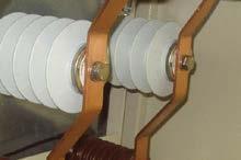


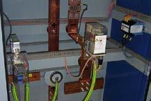
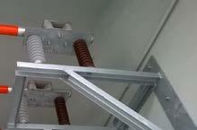

34 Reference Photo of installation 33
35 Notes 34
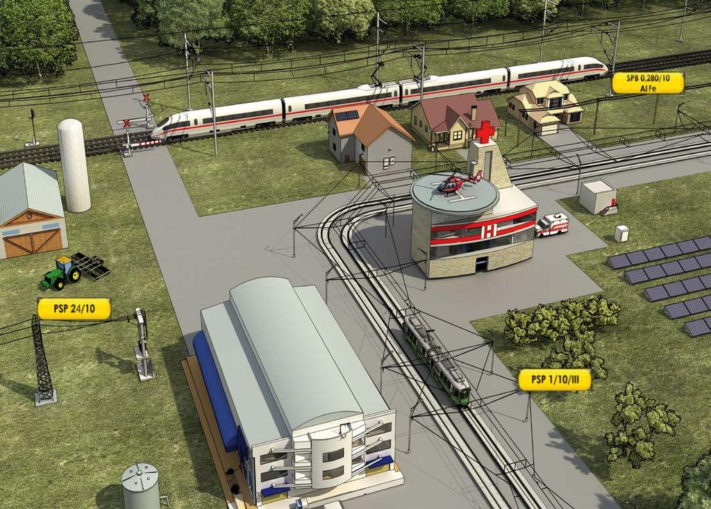


36
CONTENT OF THE CATALOGUE
 CONTENT OF THE CATALOGUE Page COMPANY PROFILE ACER VOLTAGE 2 OVERVOLTAGE DEFINITIONS, OVERVOLTAGE LIMITERS ZnO 3 DIMENSIONING OF OVERVOLTAGE LIMITERS 4 CONNECTING OF THE OVERVOLTAGE LIMITERS, THEIR MAINTENANCE
Voltage limiting device HVL
 Datasheet Voltage limiting device HVL 120-0.3 1 2 3 3 Equivalent circuit of voltage limiting device Type HVL 120-0.3 1 MO-surge arrester 2 Trigger electronics 3 Thyristor Product Description The HVL 120-0.3
Voltage limiting device HVL
 Datasheet Voltage limiting device HVL 60-0.3 1 2 3 3 Equivalent circuit of voltage limiting device Type HVL 60-0.3 1 MO-surge arrester 2 Trigger electronics 3 Thyristor Product Description The HVL 60-0.3
Surge arrester POLIM-H..SD
 Data sheet Surge arrester POLIM-H..SD Technical data Classification according to EN 50526-1 and IEC 62848-1 Nominal discharge current I n (8/20 µs) 10 ka peak Class DC-B High current impulse I hc (4/10
Surge arrester POLIM-H.. ND
 DATA SHEET Surge arrester POLIM-H.. ND Technical data Classification according to EN 50526-1 and IEC 62848-1 Nominal discharge current I n (8/20 µs) 10 ka peak Class DC-B High current impulse I hc (4/10
Surge arrester POLIM-C.. HD
 DATA SHEET Surge arrester POLIM-C.. HD Technical data Classification according to EN 50526-1 and IEC 62848-1 Nominal discharge current I n (8/20 µs) 10 ka peak Class DC-A High current impulse I hc (4/10
CONTENTS About the company 1. Low-voltage arresters LVA type 2. Metal-oxide surge arresters for distribution systems. 3.
 CONTENTS About the company 4 1. Low-voltage arresters LVA type 5 2. Metal-oxide surge arresters for distribution systems. 6 2.1 PA-DM type 6 Dimensions of arresters of PA-DM 9 2.2 PA-DH types 10 Dimensions
MEDIUM VOLTAGE NETWORKS
 MEDIUM VOLTAGE NETWORKS LIGHTNING ARRESTERS & INSULATORS SICAME GROUP OUR EXPERIENCE With 25 years of experience in the field of over protection for medium lines, DERVASIL designs and manufactures zinc
HIGH VOLTAGE SURGE ARRESTER SPECIFICATION
 HIGH VOLTAGE SURGE ARRESTER SPECIFICATION Applications: (Polymer housed MOA for 110kv) (The polymer housed MOA for 10kv) (Porcelain housed MOA for 220kv) (35kv MOA without gaps for middle phase) (110kv
Independent Testing Laboratory for High Voltage Equipment
 T E S T I N G L A B O R A T O R Y Independent Testing Laboratory for High Voltage Equipment 1 CHALLENGING ENVIRONMENT The primary concern for utilities is to ensure grid reliability, efficiency, and security.
Energy Division. PCA Single Column Polymeric Surge Arrester
 Energy Division PCA Single Column Polymeric Surge Arrester Bowthorpe EMP pioneered the development of the polymeric composite housed surge arrester in the early 1980 s and since 1986 has a proven service
3EQ Composite Housed Surge Arresters Saving Money and Space, Gaining Reliability
 3EQ Composite Housed Surge Arresters Saving Money and Space, Gaining Reliability Power Transmission and Distribution 1 A perfect Combination of Cost-Savings, Safety and Reliability 3EQ Surge Arresters:
INTRODUCTION. The plug-in connection on the cables and lightning arrestors, allows for easy installation and replacement.
 INTRODUCTION The Power Systems 44 kv MiniSub TM is the most compact system at this voltage available. Utilizing a deadfront termination and lightning arrestor setup, it eliminates the line top or side
Surge Arresters. Supply Program. Answers for energy.
 Surge Arresters Supply Program www.siemens.com/energy/arrester Answers for energy. Always the Best Solution We offer an extensive range of surge arresters suitable for every application economical and
3EK7 Distribution Class Surge Arresters. Answers for energy.
 3EK7 Distribution Class Surge Arresters Answers for energy. Siemens at Your Service As a global leader of the electronics industries, Siemens has been active in the fields of power transmission and distribution
3EQ Composite Housed Surge Arresters
 Power Transmission and Distribution 3EQ Composite Housed Surge Arresters Saving Money and Space, Gaining Reliability A perfect Combination of Cost-Savings, Safety and Reliability 3EQ Surge Arresters: Your
3EK7 Distribution Class Surge Arresters. Answers for energy.
 3EK7 Distribution Class Surge Arresters Answers for energy. Siemens at Your Service As a global leader of the electronics industries, Siemens has been active in the fields of power transmission and distribution
Zinc Oxide Surge Arrester EXLIM R
 Zinc Oxide Surge Arrester EXLIM R Protection of switchgear, transformers and other equipment in high systems against atmospheric and switching overs. For use when requirements of lightning intensity, energy
Surge arresters Product overview
 Surge arresters Product overview abb Surge arresters from ABB Switzerland ABB Switzerland Ltd has been developing and manufacturing for over a century, metal-oxide (MO) resistors and MO arresters for worldwide
High Voltage Surge Arresters Station Class
 Power Transmission and Distribution High Voltage Surge Arresters Station Class Product Overview High Voltage High Protection Just as the Golden Gate Bridge has successfully defied all winds, weather and
ABB Switzerland Ltd Phone Surge arresters Telefax:
 Operating Manual Publication number 1HC0023892 Low Voltage Limiter Type HVL 120-0.3 With metal oxide varistor and thyristors from ABB Silicon housing material for indoor and outdoor applications Transport,
3EK7 Medium Voltage Silicone Insulated Surge Arresters
 3EK7 Medium Voltage Silicone Insulated Surge Arresters Power Transmission and Distribution Setting new Standards The 3EK7 s mechanical features: Glass-collared MOV, Silicone rubber housing, FRP rods and
Silicone Suspension/Tension Insulator 120kN. up to LIWV 450kV (BIL)
") Silicone Suspension/Tension Insulator 120kN up to LIWV 450kV (BIL) CABLE SYSTEMS FOR ENERGY & ROLLING STOCK APPLICATIONS MV Silicone Tension Insulators The high tensile strength of glass fibre has been
Silicone Suspension/Tension Insulator 120kN up to LIWV 450kV (BIL) CABLE SYSTEMS FOR ENERGY & ROLLING STOCK APPLICATIONS MV Silicone Tension Insulators The high tensile strength of glass fibre has been
Surge arresters for railway applications. Product guide. Siemens HP-AR 41. siemens.com/arresters
 Surge arresters for railway applications Product guide HP-AR 41 Siemens 2017 siemens.com/arresters Siemens surge arresters for railway applications reliable, stable and safe over protection electrification.
Zinc Oxide Surge Arrester PEXLIM Q
 Zinc Oxide Surge Arrester Protection of switchgear, transformers and other equipment in high voltage systems against atmospheric and switching overvoltages. in areas with high lightning intensity and high
Overview Overvoltage protection
 A P P L I C AT I O N N OT E 1.0 Overview Overvoltage protection The APPLICATION NOTES (AN) are intended to be used in conjunction with the APPLICATION GUIDELINES Overvoltage protection Metal-oxide surge
Shielded surge arresters
 Shielded surge arresters Nexans, worldwide leader for the cable industry Total sales of billion euros in 2009 The most complete range of cables and cabling systems Plants in 39 countries 22,700 employees
3EP1 Surge Arrester. Metal-oxide surge arrester without series gaps for high-voltage systems up to U m. = 170 kv
 3EP1 Surge Arrester Metal-oxide surge arrester without series gaps for high-voltage systems up to U m = 170 kv Rated voltage up to 180 kv Nominal discharge current 10 ka, 8/20 µs Line discharge class LD1,
Type HS PEXLIM-P Surge Arresters Maximum System Voltage 123 kv to 800 kv
 Type HS PEXLIM-P Surge Arresters Maximum System Voltage 123 kv to 800 kv HS PEXLIM-P Metal Oxide Surge Arrester HS PEXLIM-P Surge Arresters are used for the protection of switchgear, transformers and other
Zinc-Oxide Surge Arrester TEXLIM Q-C
 Zinc-Oxide Surge Arrester TEXLIM Q-C Protection of switchgear, transformers and other equipment in high systems against atmospheric and switching overs. in areas with very high lightning intensity where
Directly Molded Polymer Surge Arresters
 Directly Molded Polymer Surge Arresters Ideal means to reduce environmental impact Up to 420kV, Comply with IEC60099-4, Line discharge class 2-4 l Long-life performance (Hydrophobic silicone rubber) l
Surge Arresters. UltraSIL Housed VariSTAR Station Class Surge Arresters GENERAL CONSTRUCTION
 Surge Arresters UltraSIL Housed VariSTAR Station Class Surge Arresters Electrical Apparatus 235-88 GENERAL Cooper Power Systems has set a new standard of excellence for polymerhoused station class surge
SLOVAK UNIVERSITY OF TECHNOLOGY Faculty of Material Science and Technology in Trnava ELECTRICAL ENGINEERING AND ELECTRONICS.
 SLOVAK UNIVERSITY OF TECHNOLOGY Faculty of Material Science and Technology in Trnava ELECTRICAL ENGINEERING AND ELECTRONICS Róbert Riedlmajer TRNAVA 2007 Unit 14 - Fundamentals of power system protection
Type SIMOPRIME A4, up to 24 kv, Air-Insulated Medium-Voltage Switchgear
 Circuit-Breaker www.siemens.com/energy Switchgear Type SIMOPRIME A4, up to 24 kv, Air-Insulated Medium-Voltage Switchgear s Technology Circuit-Breaker Switchgear Type SIMOPRIME, up to 17.5 kv, Air-Insulated
Surge-Trap Pluggable STPT2 Series - 40kA
 Surge-Trap Pluggable STPT2 Series - 40kA SURGE PROTECTION FOR POWER LINES DIN-RAIL IEC TYPE 2 / CLASS II FEATURES & BENEFITS Maximum discharge current (8/20μs): 40kA per phase Nominal discharge current
High Voltage Surge Arresters Buyer s Guide Section Transmission Line Arrester PEXLINK
 High Voltage Surge Arresters Buyer s Guide Section Transmission Line Arrester PEXLINK Definitions Transmission Line Arresters Backflashover Occurs when lightning strikes the tower structure or overhead
Domae. The right solution for distribution boards
 Domae The right solution for distribution boards Guaranteed quality and adapted solutions Domae : SIRIM approved The quality marks prove product conformity to their reference standard. They guarantee:
BOWTHORPE EMP MEH SURGE ARRESTERS (IEC) ENERGY /// MEH SURGE ARRESTERS IEC
 ENERGY /// MEH SURGE ARRESTERS IEC") BOWTHORPE EMP MEH SURGE ARRESTERS (IEC) GENERIC TECHNICAL DATA Maximum system voltage U m 800 System voltage U s 750 Nominal discharge current ka 20 High current impulse (4/10 µs) ka 100 Arrester class
BOWTHORPE EMP MEH SURGE ARRESTERS (IEC) GENERIC TECHNICAL DATA Maximum system voltage U m 800 System voltage U s 750 Nominal discharge current ka 20 High current impulse (4/10 µs) ka 100 Arrester class
Surge arrester POLIM-H..N
 Data sheet Surge arrester POLIMH..N Technical data Arrester class SH, Station High Line discharge class (LD) 4 Nominal discharge current I n (8/20 µs) 20 ka peak Repetitive charge transfer rating Q rs
FUSES. Safety through quality
 Safety through quality HH HIGH VOLTAGE Over many decades SIBA has developed a global product line of High Voltage Fuses that are comprehensive for any and all applications. Superior engineering, advanced
Contactors. CH1130/02 Series Single pole high-voltage contactor up to 3 kv Catalogue C170.en. Connect - Contact - Control
 Connect - Contact - Control 3 Contactors CH1130/02 Series Single pole high-voltage contactor up to 3 kv Catalogue C170.en More information at: schaltbau-gmbh.com 42 CH1130/02 Single pole high-voltage contactor
THP145 HYBRID GAS INSULATED SWITCHGEAR (HGIS) Energy, Fast! tgood.com
 Energy, Fast! tgood.com") THP145 HYBRID GAS INSULATED SWITCHGEAR (HGIS) Energy, Fast! tgood.com TGOOD produces over 5000 switchgear units annually for projects around the globe SOLUTION OVERVIEW For use in affordable air insulated
THP145 HYBRID GAS INSULATED SWITCHGEAR (HGIS) Energy, Fast! tgood.com TGOOD produces over 5000 switchgear units annually for projects around the globe SOLUTION OVERVIEW For use in affordable air insulated
Transformer bushings, type GOH. Technical guide
 Transformer bushings, type GOH Technical guide This Technical Guide has been produced to allow transformer manufacturers, and their designers and engineers, access to all the technical information required
Bowthorpe EMP LV/MV Outdoor Surge Arresters
 Bowthorpe EMP LV/MV Outdoor Surge Arresters Bowthorpe EMP LV/MV Surge Arresters for Outdoor Applications Table of Contents Product Classification Voltage Range Page DA Series Distribution Metal Oxide Surge
power cable accessories
 power cable accessories kv up to 4 kv Completing the picture based on experience is the future nkt cables GmbH NKT was established in 89 as cable manufacturer. In 999 NKT A/S Denmark merged with Felten
1ZSE en, Rev. 3. Wall bushings, type GSA-AA Technical guide
 1ZSE 2750-112 en, Rev. 3 Wall bushings, type GSA-AA Technical guide Original instruction The information provided in this document is intended to be general and does not cover all possible applications.
045 : 2000 CEB STANDARD
 045 : 2000 CEB STANDARD LOW VOLTAGE FUSE SWITCH DISCONNECTOR CEYLON ELECTRICITY BOARD SRI LANKA Specification for LOW VOLTAGE FUSE SWITCH DISCONNECTOR CEB Standard 045 : 2000 CEYLON ELECTRICITY BOARD No.
Surge Arrester 3EL2 superior protection up to 550 kv
 Certified according to IEC 60099-4 Edition 2.1 (2006) Surge Arrester 3EL2 superior protection up to 550 Light weight. Strong performance. Answers for energy. Simply irresistible. By resisting wear in any
Medium-voltage fuses 3 kv 40.5 kv, 0.4 A 315 A
 DISTRIBUTION SOLUTIONS Medium-voltage fuses 3 kv 40.5 kv, 0.4 A 315 A Continuous protection and reliable operation Proven design and compliance with newest fuses standards Compatibility with other ABB
BOWTHORPE EMP MCA/MDA SURGE ARRESTERS (IEC) ENERGY /// MCA/MDA SURGE ARRESTERS IEC
 ENERGY /// MCA/MDA SURGE ARRESTERS IEC") BOWTHORPE EMP MCA/MDA SURGE ARRESTERS (IEC) GENERIC TECHNICAL DATA MCA MDA Maximum system voltage U m 420 550 System voltage U s 400 500 Nominal discharge current ka 10 20 High current impulse (4/10 µs)
BOWTHORPE EMP MCA/MDA SURGE ARRESTERS (IEC) GENERIC TECHNICAL DATA MCA MDA Maximum system voltage U m 420 550 System voltage U s 400 500 Nominal discharge current ka 10 20 High current impulse (4/10 µs)
VariSTAR Type AZE station-class surge arresters for systems through 345 kv IEEE certified
 Surge s Catalog Data CA235022EN Supersedes TD235009EN September 2014 COOPER POWER SERIES VariSTAR Type AZE station-class surge arresters for systems through 345 kv IEEE certified General Eaton s Cooper
Circuit-Breaker Switchgear Type SIMOPRIME, up to 17.5 kv, Air-Insulated Medium-Voltage Switchgear.
 Circuit-Breaker Switchgear Type SIMOPRIME, up to 17.5 kv, Air-Insulated Medium-Voltage Switchgear www.siemens.com/energy Technology s Contents Application Page Benefits 2 Typical uses 2 and 3 Technical
1ZSE EN, REV. 4. Wall bushings type GSA-AA Technical guide
 1ZSE 2750-112 EN, REV. 4 Wall bushings type GSA-AA Technical guide Original instruction The information provided in this document is intended to be general and does not cover all possible applications.
power pazifik Metal Oxide Surge Arrester with composite polymer insulator Type series SBK-I to IV /10.3
 Manufactured by: Metal Oxide Surge Arrester with composite polymer insulator Type series SBK-I to IV-6... 150/10.3 BT-A3/8 Surge Arresters housed in polymer housing, developed to protect switchgear, over
The University of New South Wales. School of Electrical Engineering and Telecommunications. Industrial and Commercial Power Systems Topic 2
 The University of New South Wales School of Electrical Engineering and Telecommunications Industrial and Commercial Power Systems Topic 2 SWITCHBOARDS Overview Also called Switchgear and Controlgear Assembly
Switchgear Type 8BT1, up to 24 kv, air-insulated. Medium Voltage Switchgear Catalog HA 26.
 www.siemens.com/medium-voltage-switchgear Switchgear Type 8BT1, up to 24 kv, air-insulated Medium Voltage Switchgear Catalog HA 26.31 2012 Answers for infrastructure and cities. R-HA26-013. eps Contents
MEDIUM VOLTAGE PRODUCTS. Fault Current Limiters I S. -limiter and FC-Protector The worldʼs fastest switching devices
 MEDIUM VOLTAGE PRODUCTS The worldʼs fastest switching devices 2 FAULT CURRENT LIMITERS THE WORLDʼ S FASTETST SWITCHING DEVICES The worldʼs fastest switching devices ABBʼs fault current limiters disconnect
VEIKI-VNL Electric Large Laboratories Ltd. H-1158-Budapest, Vasgolyó utca 2-4. HUNGARY
 VEIKI-VNL Electric Large Laboratories Ltd. H-1158-Budapest, Vasgolyó utca 2-4. HUNGARY VEIKI-VNL Ltd. VEIKI-VNL Electric Large Laboratories Ltd. is an independent accredited testing member laboratory of
I Surge Arresters. UltraSIL Polymer-Housed VariSTAR Type U3 Surge Arrester for Systems through 275 kv IEC 10 ka; Line Discharge Class 3 GENERAL
 Surge Arresters UltraSIL Polymer-Housed VariSTAR Type U3 Surge Arrester for Systems through 275 kv IEC 10 ka; Line Discharge Class 3 Electrical Apparatus I235-93 GENERAL UltraSIL Polymer-Housed VariSTAR
Resin Impregnated Paper Bushing, Oil to Air, Type GSB Technical guide
 1ZSC000563-AAC en, Rev. 2 Resin Impregnated Paper Bushing, Oil to Air, Type GSB Technical guide This Technical Guide has been produced to allow transformer manufacturers, and their designers and engineers,
GENERAL. CONSTRUCTION External
 Surge Arresters VariSTAR Type AZG4 Surge Arresters for Systems through 400 kv IEC 20-kA; Line Discharge Class 4 Electrical Apparatus I235-84 GENERAL VariSTAR AZG4 Surge Arresters incorporate the latest
Major changes within the New 18 th Edition Wiring Regulations announced by The IET
 Major changes within the New 18 th Edition Wiring Regulations announced by The IET BS 7671:2018 Requirements for Electrical Installations will be issued on 2 nd July 2018 and is intended to come into effect
Product presentation CPT tech Jason Evershed, ABB Transformer Components, May 21st Dry-type transformers Innovative Technology
 Product presentation CPT tech Jason Evershed, ABB Transformer Components, May 21st 2014 Dry-type transformers Innovative Technology What is a dry transformer? ABB manufactures a transformer which does
Benefits, typical uses
 R-HA26-013. eps Switchgear Type 8BT1, up to 24kV,Air-Insulated Contents Application Page Application Benefits 2 Typical uses 2 and 3 Technical Data Ratings 4 Classification, dimensions, 5 room planning
CAST RESIN DISTRIBUTION TRANSFORMERS 2016 EDITION
 CAST RESIN DISTRIBUTION TRANSFORMERS 2016 EDITION TMC TRANSFORMERS - GLOBAL NETWORK UK & IRELAND SPAIN NORTH AMERICA & CANADA GERMANY SWITZERLAND BENELUX & AUSTRIA ITALY POLAND INDIA CENTRAL & SOUTH AMERICA
Step 1: Collection of required data
 Step 1: Collection of required data If the relevant parameters of the interfaces are known, it is possible to dimension ASSEMBLIES 3 Installation and environmental conditions 4 Operating and servicing
Characteristics of LV circuit breakers Releases, tripping curves, and limitation
 Characteristics of LV circuit breakers Releases, tripping curves, and limitation Make, Withstand & Break Currents A circuit breaker is both a circuit-breaking device that can make, withstand and break
Range 16A to 63A. Sensitivity 30mA, 100mA, 300mA, 500mA. Execution Double Pole, Four Pole. Specification IEC / IS : 2000
 The flow of current through electrical facilities always involves risks. Poorly insulated equipment, faulty wires and incorrect use of an electrical devise cause currents to flow through the wrong path
Title High Voltage and 1500 System Earthing References and Definitions. Reference Number PDS 02 (RIC Standard: EP SP)
") Discipline Engineering Standard NSW Category Electrical Title High Voltage and 1500 System Earthing References and Definitions Reference Number PDS 02 (RIC Standard: EP 12 00 00 01 SP) Document Control
Discipline Engineering Standard NSW Category Electrical Title High Voltage and 1500 System Earthing References and Definitions Reference Number PDS 02 (RIC Standard: EP 12 00 00 01 SP) Document Control
NXPLUS C Single busbar. Maintenance-free for lifetime
 NXPLUS C Single busbar Maintenance-free for lifetime Energy Distribution Welcome! Page 2 Content Overview Technical data Typicals Panel design Circuit-Breaker panel Busbar Operation Metering Low-voltage
Eskom s unique type test requirements for lightning surge arrester ground lead disconnectors
 Eskom s unique type test requirements for lightning surge arrester ground lead disconnectors Author & Presenter: R Theron M.Eng Chief Engineer Co-author: H Geldenhuys Phd Corporate Specialist (Technology
Type POLIM-S Surge Arresters Maximum System Voltage 2.52 to 245 kv
 Type POLIM-S Surge Arresters Maximum System Voltage 2.52 to 245 kv POLIM-S Metal Oxide Gapless Surge Arresters POLIM-S Surge Arresters are used for the protection of switchgear, transformers and other
RESIDUAL CURRENT CIRCUIT BREAKER
 Quality Features Mid Trip - Different knob position to indicate whether the device is Switched OFF by a fault or Switched OFF manually Inscription Window - Ensures circuit identification and hence reduces
Changing of the guard Polymer replaces porcelain for surge arresters
 Changing of the guard Polymer replaces porcelain for surge arresters Torbjörn Skytt, Hans E. G. Gleimar Standing guard may be the best description of what surge arresters do, but it says nothing about
Grounding systems for power supply facilities
 MATEC Web of Conferences 141, 01052 (2017) Grounding systems for power supply facilities Vladimir Konusarov 1,*, and Ekaterina Tarasova 2 1 National Research Tomsk Polytechnic University, 634050 Tomsk,
B kv Gas-insulated Substations
 72.5 145 kv Gas-insulated Substations The increasing demand for electrical power in cities and industrial centres requires the installation of a compact and efficient distribution and transmission network.
SF 6 Gas Insulated Switchgear Type SDH714 for 72.5 to 145 kv
 Three-phase Encapsulated Type SF 6 Gas Insulated Switchgear Type SDH714 for 72.5 to 145 kv 06B1-E-0020 Small Space Requirement, High Reliability and Safety ー 72.5 to 145kV GIS, SDH714 The number of application
Technical Information Solid State Relays. Glossary. Solid State Relays
 Glossary Terms Meaning Circuit functions Photocoupler Transfers the input signal and insulates inputs and outputs as well. Photoctriac coupler Zero cross circuit Trigger circuit Snubber circuit A circuit
Resin Impregnated Paper Bushing, Oil to SF 6. , Type GSBK
 1ZSC563-AAA en, Rev. 2 Resin Impregnated Paper Bushing, Oil to SF 6, Type GSBK Technical guide This Technical Guide has been produced to allow transformer manufacturers, and their designers and engineers,
Rolling Stock Cables Supplement to Prysmian Group General Catalogue (CEE Region)
") Rolling Stock Cables Supplement to Prysmian Group General Catalogue (CEE Region) Rolling Stock Cables Supplement to Prysmian Group General Catalogue (CEE Region) Linking the Future As the worldwide leader
Rolling Stock Cables Supplement to Prysmian Group General Catalogue (CEE Region) Rolling Stock Cables Supplement to Prysmian Group General Catalogue (CEE Region) Linking the Future As the worldwide leader
023 : 2006 CEB STANDARD. 12kV & 36kV LOAD BREAK SWITCHES CEYLON ELECTRICITY BOARD SRI LANKA
 023 : 2006 CEB STANDARD 12kV & 36kV LOAD BREAK SWITCHES CEYLON ELECTRICITY BOARD SRI LANKA Specification for 12kV & 36kV LOAD BREAK SWITCHES CEB Standard 023 : 2006 CEYLON ELECTRICITY BOARD No. 50, Sir
B kv T&D GAS INSULATED SWITCHGEAR
 GAS INSULATED SWITCHGEAR B 105 170 300 kv The increasing demand for electrical power in cities and industrial centers necessitates the installation of a compact and efficient distribution and transmission
High Voltage Surge Arresters Buyer s Guide Section PEXLIM R
 High Voltage Surge Arresters Buyer s Guide Section PEXLIM R Zinc Oxide Surge Arrester PEXLIM R Protection of switchgear, transformers and other equipment in high systems against atmospheric and switching
Miniature Circuit-Breakers (MCBs)
") Product Overview Miniature Circuit-Breakers (MCBs) Design Tripping characteristics Rated current I n Rated breaking capacity Power supply company product range 5SP3 E 16 - A Standard product range 5SQ2
Product Overview Miniature Circuit-Breakers (MCBs) Design Tripping characteristics Rated current I n Rated breaking capacity Power supply company product range 5SP3 E 16 - A Standard product range 5SQ2
All rights reserved. Neither this catalogue nor any part of it may be copied using any method or for any purposes. Most studies are legally protected.
 Issued: January 2013 Copyright by ZPUE Katowice S.A. All rights reserved. Neither this catalogue nor any part of it may be copied using any method or for any purposes. Most studies are legally protected.
Electronic Ballast EVG 2000-T
 Electronic Ballast EVG 2000-T Operating Manual Table of contents 1 Description 1.1 Advantages of this ballast... 3 1.2 Functional principle... 3 1.3 Energization... 4 1.4 Visualization... 5 1.5 Indications
Our brand POWER DYNAMIC PASSION COMMITMENT CREATIVITY. A strong brand for strong products: 8PU Premium. MV Energy
 Our brand A strong brand for strong products: The ENERGOLINE brand represents our product portfolio of INDUSTRIAL SWITCHGEAR SYSTEMS. Our products are characterized by a high degree of safety, flexibility
Medium voltage fuses - European Fuses
 HV Back-up Fuse-Links according to IEC 60 282- HV fuse-links have been used for reliable protection in medium-voltage switchgear and controlgear and systems for decades. They protect apparatus and equipment
KEWTECH. KT56 digital multi function tester. Instruction manual
 KEWTECH KT56 digital multi function tester Instruction manual Contents 1 Safety Notice 1 2 Features and Principles of Measurement 3 3 Introduction 6 4 Specifications 7 5 Instrument layout 9 6 Operating
ENERGY /// TRANSMISSION LINE SURGE ARRESTERS IEC. Bowthorpe EMP Transmission Line Surge Arresters (IEC)
") ENERGY /// TRANSMISSION LINE SURGE ARRESTERS IEC Bowthorpe EMP Transmission Line Surge Arresters (IEC) TRANSMISSION LINE SURGE ARRESTERS Numerous technical publications have stated that lightning is responsible
ENERGY /// TRANSMISSION LINE SURGE ARRESTERS IEC Bowthorpe EMP Transmission Line Surge Arresters (IEC) TRANSMISSION LINE SURGE ARRESTERS Numerous technical publications have stated that lightning is responsible
1ZSC AAA en, Rev. 6. Resin impregnated paper bushing, oil to SF 6., type GSBK Technical guide
 1ZSC563-AAA en, Rev. 6 Resin impregnated paper bushing, oil to SF 6, type GSBK Technical guide Original instruction The information provided in this document is intended to be general and does not cover
Earthing Principles. Symmetra PX 250/500 kw
 Earthing Principles Symmetra PX 250/500 kw Table of Contents Earthing Principles... 1 Decoding the Earthing Types... 1 TN Systems... 2 Characteristics... 2 Reference to IEC/EN 60364-4-41 413.1.3... 2
MINI MCR-SL-UI-UI(-SP)(-NC)
(-NC)") Configurable 3-Way Isolating Amplifier Data Sheet 04/2005 Functions Features The configurable 3-way isolating amplifier MINI MCR-SL-UI-UI(-SP)(-NC) is used to electrically isolate, condition, amplify,
Configurable 3-Way Isolating Amplifier Data Sheet 04/2005 Functions Features The configurable 3-way isolating amplifier MINI MCR-SL-UI-UI(-SP)(-NC) is used to electrically isolate, condition, amplify,
Key elements of the AS3000 Wiring standards and some of the recent changes.
 Key elements of the AS3000 Wiring standards and some of the recent changes. Dean of Engineering Steve Mackay Worked for 30 years in Industrial Automation 30 years experience in mining, oil and gas, electrical
ELECTRIC TRACTION.
 ELECTRIC TRACTION www.koncar.hr MODERNISATION ELECTRIC TRACTION VEHICLES Company KON AR - ELECTRIC VEHICLES Inc. upgrades electric locomotives, electric multiple unit and electric tramcars. Upgrading proceedings
3 RD RAIL SWITCH FHT-KS 4000 DISCONNECTOR
 3 RD RAIL SWITCH FHT-KS 4000 DISCONNECTOR www.kraus.com www.kraus.com KRAUS RAILWAY TECHNOLOGY PRODUCT LINE Pantograph Switches Trackside Disconnectors Disconnectors & Earthing Switches Pneumatic Interlock
CPG.1 Gas insulated, single busbar cubicle range Up to 27 kv / 2000 A / 31.5 ka Up to 38 kv / 2000 A / 31.5 ka IEEE Standards
 Medium Voltage Switchgear Primary Distribution CPG.1 Gas insulated, single busbar cubicle range Up to 27 kv / 2000 A / 31.5 ka General description Presentation Ormazabal s CPG System includes the CPG.1
KYN28-12(GZSI-12Z)Armoured Middle-Mounted Metal. Enclosed Switch. 1.General. 2.Model Definition
Armoured Middle-Mounted Metal. Enclosed Switch. 1.General. 2.Model Definition") KYN28-12(GZSI-12Z)Armoured Middle-Mounted Metal Enclosed Switch 1.General KYN28-12 armoured middle-mounted metal enclosed switchgear (hereinafter referred to as switchgear) is a new product with own design
KYN28-12(GZSI-12Z)Armoured Middle-Mounted Metal Enclosed Switch 1.General KYN28-12 armoured middle-mounted metal enclosed switchgear (hereinafter referred to as switchgear) is a new product with own design
Solid State Relays, 3-phase
 PMA Prozeß- und Maschinen-Automation GmbH Solid State Relays, 3-phase Zero-Point switching, heatsink integrated Main Characteristics: Three-phase controlled Zero switching LED display Various connection
Electrical Test of STATCOM Valves
 21, rue d Artois, F-75008 PARIS 619 CIGRE 2016 http : //www.cigre.org Electrical Test of STATCOM Valves Baoliang SHENG 1, Christer DANIELSSON 1, Rolf NEUBERT 2, Juha TURUNEN 3, Yuanliang LAN 4, Fan XU