CONTENT OF THE CATALOGUE
|
|
|
- Marcia Ramsey
- 5 years ago
- Views:
Transcription
1 CONTENT OF THE CATALOGUE Page COMPANY PROFILE ACER VOLTAGE 2 OVERVOLTAGE DEFINITIONS, OVERVOLTAGE LIMITERS ZnO 3 DIMENSIONING OF OVERVOLTAGE LIMITERS 4 CONNECTING OF THE OVERVOLTAGE LIMITERS, THEIR MAINTENANCE AND CONTROL 5 OVERVOLTAGE LIMITERS, AC NETWORK, SERIES PSP */5 ka - DISCHARGE CLASS 1 6 INDOOR AND OUTDOOR USE OVERVOLTAGE LIMITERS, AC NETWORK, SERIES PSP */10 ka - DISCHARGE CLASS 1 7 INDOOR AND OUTDOOR USE OVERVOLTAGE LIMITERS, DC NETWORK, SERIES PSP */10/III - DISCHARGE CLASS 3 8 INDOOR AND OUTDOOR USE OVERVOLTAGE LIMITERS, DC NETWORK, SERIES PSPI */10/III - DISCHARGE CLASS 3 9 INDOOR USE OVERVOLTAGE LIMITERS, DC NETWORK, SERIES PSP */20/IV - DISCHARGE CLASS 4 10 INDOOR AND OUTDOOR USE OVERVOLTAGE LIMITERS, DC NETWORK, SERIES PSPI */20/IV - DISCHARGE CLASS 4 11 INDOOR USE OVERVOLTAGE LIMITERS, AC NETWORK, SERIES PSPI */10 - DISCHARGE CLASS 1 12 INDOOR USE OVERVOLTAGE LIMITERS, AC NETWORK, SERIES PSPN */10/III - DISCHARGE CLASS 3 13 INDOOR USE UNIVERSAL SURGE ARRESTER AC AND DC NETWORKS SERIES SPDXXXFM TYPE 2 + TYPE 3 14 INDOOR USE SPDXXXFM, SUMMARY OF PRODUCED TYPES 15 - AC NETWORK U N = VAC - DC NETWORK U N = VDC P60G AND P120G, LOW VOLTAGE LIMITERS FOR RAILWAY APPLICATIONS 16 INDOOR AND OUTDOOR USE P400G AND P250G, POWER GAS DISGARGE TUBES FOR POTENTIAL EQUALISATION 17 ON METAL PARTS OF INDUSTRIAL TECHNOLOGY INDOOR AND OUTDOOR USE P600G, POWER GAS DISGARGE TUBES FOR POTENTIAL EQUALISATION 18 ON METAL PARTS OF INDUSTRIAL TECHNOLOGY INDOOR AND OUTDOOR USE SURGE ARRESTERS SPB */10 PP ON FLAT BUSBARS 19 INDOOR AND OUTDOOR USE SURGE ARRESTERS SPB */10 AlFe ON BARE OVERHEAD CONDUCTORS 20 INDOOR AND OUTDOOR USE SURGE ARRESTERS SPB */10 S ON INSULATED OVERHEAD CONDUCTORS 21 INDOOR AND OUTDOOR USE CHARACTERISTICS AND PERRORMANCE OF SURGE ARRESTERS SPB */10 22 NOTES 23 REFERENCE, PHOTOS 24 1


2 A satisfied customer is our aim at all times Professional surge arresters and overvoltage limiters Protection of the power supply of trolley lines, distribution transformers and LV electrical equipment in AC networks... Applications for transport companies and railways Protection of converter stations and DC networks of electric traction systems linked to them, electrical equipment of trolleybuses, trams and electric locomotives... Protection against atmospheric and switching overvoltage Protection of HV transmission networks, transformers, switchgear and HV cable distribution systems... COMPANY PROFILE ACER VOLTAGE Ltd. was founded in 1992 in Hradec Kralove, originally called ACER. It is a purely Czech company which is engaged in the development and production of surge arresters and overvoltage limiters for the protection of LV and HV power distribution networks and protect equipment against lightning and switching overvoltage. Furthemore, it also focuses on the production of composite insulators. Products of ACER VOLTAGE company protects of its customers equipment from the devastating effects of the surge. This company acted since 2006 under the name ACER HK Ltd. and in the end 2014 moved into a new place of work, where it remains. In 2016, the company renamed to its current name ACER VOLTAGE Ltd. that better reflects its focus and activities. In the past, the company developed and manufactured varistors based on ZnO surge arresters in the LV applications and then another surge arresters made from them. The first type was a surge arrester SP / 10, which has been improved and is now produced only in design SPB * / 10 in various voltage levels acc. to type of installation. Production of ZnO varistors was abolished in 2006, and for current and surge arresters are only used varistors from external suppliers. Another significant part of production program are polymeric arresters for HV networks of 1-39 kv for AC or DC networks. They consist of the entire model range, which is constantly expanding. In addition, it is possible to produce nonstandard types according to customer requirements and specifications. Details about today s sortiment ACER VOLTAGE can be found at our catalog or website. Recently was expanded assortment of products with gas-filled power arresters. The Company has acquired and regularly renews certification according to DIN EN ISO 9001 certified. ACER VOLTAGE is a leading company supplying technology for power and automation that enable energy and industry could increase its efficiency while reducing their impact on the environment. ACER VOLTAGE products are delivered to 42 countries and are always close to its customers. With superior technology, global scale, deep industry expertise and local knowledge, we can offer our customers products, system solutions and services that help improve the reliability of their transmission networks. Due to focus and strengths in technologies for power and automation, we strive for organic growth. Our global manufacturing base ensures consistent products and systems of the highest quality produced in the ACER VOLTAGE for customers worldwide. Our customers have easy access to a full range of products, either directly with us as the manufacturer, or through a network of distributors or wholesalers, which is constantly expanding.to ensure the quality of products the company ACER VOLTAGE performs 100% inspection at production testing equipment. With these devices are controlled precise technical specifications throughout the production company ACER VOLTAGE. 2
3 Overvoltage definition DEFINITION OF OVERVOLTAGE Overvoltage is voltage that exceeds the maximum value of operating voltage in an electric circuit. Pulse overvoltage, its formation and division Pulse overvoltage is short-term overvoltage, lasting in the order of nanoseconds up to milliseconds. It is one of the most noticeable and most harmful manifestations of electromagnetic interference (perturbing influences) and it poses a threat especially to electronic equipment containing semiconductor components. According to its origin, pulse overvoltage is classified into: - atmospheric overvoltage (LEMP Lighting ElektroMagnetic Pulse) - switching overvoltage (SEMP Switching ElektroMagnetic Pulse) - overvoltage formed during discharges of static electricity (ESD ElektroStatic Discharge) - overvoltage due to nuclear explosions (NEMP Nuclear ElektroMagnetic Pulse) Atmospheric overvoltage (LEMP) The most dangerous overvoltage which is induced primarily by thunderstorms with lightning discharges. Overvoltage may occur between a phase and the earth or between phase conductors. It is caused primarily by thunderstorm activity, specifically by lightning discharges, namely to overhead lines and in sections of unshilded cables. Atmospheric overvoltage may be generated by a direct or near strike of lightning into a overhead line, lightning rod, some metal structure, cable, etc. The destructive effect of lightning current is given by its high energy released in a short time, which creates conditions for inducing stress in loops accompanied by adverse changes of earth resistance. Switching overvoltage (SEMP) They are very frequent overvoltage that occurs in both low-voltage and high-voltage networks. Switching overvoltage is generated by industrial activities: - when great loads, especially inductive ones, are switched on and off, e.g. transformers or electric motors or even small household appliances, e.g. refrigerators, freezers - in the event of short circuits in a distribution network and the like. Invisible voltage pulses that are immeasurable by usual means last only several millionths or thousandths of a second, yet they can cause the destruction mainly of electronic equipment, sometimes even a short circuit and subsequent fire. ZnO overvoltage limiters Currently for the construction of surge arresters are usually used voltage dependent resistors with metal-oxide ZnO varistors, which excel symmetrical currentvoltage characteristics and a zero followed current after shock subside the surge.these basic properties allow the use of these resistors as ZnO surge limiters (arresters) without spark gaps. The parameters on the basis of which we design the limiters are as follows: - Continuous operating voltage of the limiter U C it represents the maximum value of voltage connected permanently to limiter terminals at mains frequency. - Rated voltage of the limiter U R it represents the maximum effective value of voltage for which the limiter is designed while the correct function under conditions of temporary overvoltage at mains frequency is maintained. Such voltage is defined as voltage to which the limiter is exposed for 10 seconds following previous stress. - Protective level of the limiter U P is voltage on terminals at a given shape and peak value of current passing though. - Nominal discharge current I n the peak value of an atmospheric current pulse that is used for the classification of overvoltage limiters. - Residual voltage U RES it represents residual voltage on the overvoltage limiter. It is actually the peak value of voltage that appears between terminals of the overvoltage limiter when discharge current is passing through it. - Working temperature J it represents the range of permissible ambient temperatures stated by the manufacturer for the limiter to work properly. - Line discharge class a number expressing the ability of the overvoltage limiter to absorb energy in the event that long lines are discharged. Overvoltage resistance of ZnO limiters By the magnitude of permissible energy, the overvoltage limiters are divided into five classes. The higher the class, the higher is the energy capacity of the limiter. The energy that the limiter has to absorb during overvoltage rises with the voltage of the network in which it is used. Voltage rises slower than energy. Limiters in networks with higher voltage must have a greater energy capacity than limiters in networks with lower voltage. The selection of the energy class and of the rated discharge current is based on the frequency at which the energy capacity is exceeded in the given application. An energy class expresses the ability of the limiter to absorb both atmospheric and switching overvoltage. It is stated in the units kj/kv of the limiter s voltage and is independent of nominal voltage. Energy classes 1 to 5 divide the limiters into groups according to the magnitude of the permissible energy of overvoltage that they are able to absorb without being degraded or without losing heat stability at operating voltage. The higher the class, the greater is the energy capacity of the limiter. The energy classes and an example of their use Class 1 use in HV networks without classification of class (5kA) or class 1 or 2 (10 ka) Class 2 use in 110 kv networks Class 3 use for kv networks and for cable networks Class kv long network lines Class 5 extremely extensive 750 kv cable networks 3
4 Dimensioning of the overvoltage limiters Dimensioning of the overvoltage limiters The overvoltage limiters are sized based on a particular position in the network, i.e. whether they are to protect e.g. a line outlet, a line transition into a cable or transformer. Whatever their position, they have specific conditions for protection and overvoltage stress. The design of these protective equipments for given application always project-designer decides. Selecting the operating voltage U C of limiters The operating voltage, voltage-current characteristics and all voltage parameters of the limiter are dependent upon the height of column of blocks. By contrast, all voltage parameters are set by the selection of operating voltage U C. Incorrect selection of voltage U C may have a considerably negative effect on the limiter s function. If a low U C is selected, the protective level U RES and also the risk of failure of the protected device associated with it will be favourably low. On the other hand, however, there will be a risk of thermal stress on the limiters caused by temporary overvoltage, so the probability of them failing will be high. If a high U C is selected, the risk of failure of the limiters owing to temporary overvoltage will be insignificant but a high protective level U RES will imply a higher probability of the protected devices being destroyed. The correct selection of continuous voltage U C of the limiters should mean optimum parameters of protection, hence a balanced risk of reliability of the supply for both causes. The protection parameters can be improved by connecting the limiters as close to the protected device as possible with as short interconnecting wires as possible! The limiters limit voltage to a limiter s protective level U P. A limiter s protective level U P is voltage on terminals with a given shape and peak value of current passing through. Values characterising a limiter s protective level can be found in our catalogue. It is a limiter s residual voltage U RES. Characteristics of overvoltage protection of LV and HV networks In LV and HV distribution networks with overhead lines, it is necessary to protect equipment primarily from atmospheric overvoltage. Switching overvoltage reaches substantially lower current and voltage levels than atmospheric. The greatest overvoltage in cable networks without connected overhead lines is caused by short circuits and/or switching. The primary task of protective measures which are economically fully justified is to protect the equipment of LV networks from destruction by atmospheric overvoltage by installing surge arresters and, at the same time, to enable the protection of installation by adequately reducing overvoltage in the network. Principles for positioning and wiring in low voltage networks Overvoltage limiters or surge arresters can be used in 1-phase and 3-phase networks TNC, TNS, IT and TT. typically, their connections is recommended to make between phase and grounding conductor E (or PEN with TNC networks in place of his ground). In the event that the grounding conductor is not accessible, it is necessary to use a suitable grounding electrode rod with a length at least 1 m. When designing and implementing of grounding is recommend to proceed according to PNE and PNE Generally applicable rules for connecting of overvoltage limiters 1) The overvoltage limiters and the device that is to be protected must be earthed to a common earthing system. The galvanic interconnection between the earthing terminals of the limiters and the earthing of the protected device must be as short as possible. 2) The total length of conductors a and b of connection of the limiters to the protected device must be as short as possible. 3) It is always recommended that conductor b should be as short as possible or at least shorter than conductor a. 4) Strip conductors are more suitable for connection than those with circular cross-section as with the same cross-section, becase strip conductors have smaller inductance and pulse losses of overvoltage in them are smaller. The minimum size of a connecting conductor is 6 mm. The minimum width of a strip conductor is 12 mm 2. Above all, the installation of overvoltage limiters in every application is prevention of possible damage. A seemingly considerable cost of such protections tend to be only a fraction of a per cent of the acquisition value of the technology protected and a negligible sum for possible damage caused by breakdowns and destruction of technological equipment. Unprotected electric distribution systems, computer and data networks always poses a considerable risk to their users. One-line diagram of protection with the marking of sections of conductor a and conductor b overvoltage wave 4
5 Connection of the limiters to the transformer DEFINITION OF OVERVOLTAGE overvoltage limiter Transformer 110/22 kv grounding network Ground plan of the earthing network of limiters at the transformer limiters Transformer Connection of the limiter: (a) correct connection, (b) incorrect connection Maintenance and inspection of overvoltage limiters Complexly recommendations for maintenance and inspection of overvoltage limiters ZnO are specified in EN , where such control is divided into visual inspection.alternatively complete revision include important electrical measurements. Especially this control is recommended to make: - After any changes in protective elements belonging to the system installation - Periodically, at least 1 year - After direct strike to the protected instalation 5


6 PSP */5kA - OVERVOLTAGE LIMITER - LINE DISCHARGE CLASS 1 The limiters are suitable for both outdoor and indoor use OVERVOLTAGE LIMITER PSP */5kA LINE DISCHARGE CLASS 1 AC NETWORKS PSP */5kA - OVERVOLTAGE LIMITER - LINE DISCHARGE CLASS 1 Protection of high-voltage AC networks against lightning and switching surges and fast transients. Suitable for protection of transformers, cables, motors, switchgears, and other high-voltage equipment. PSP */5kA energy class 1 overvoltage limiters designed for protecting of high-voltage transmission networks; transformers, switchgears and HV cable distribution systems against of atmospheric and switching overvoltage effects. The functional part of the limiters consists a column of varistors sized for max. continuous operating voltage U C, the outer insulating shell is made from silicon material (grey colour). The material of the shell shows high resistance to the effects of surface leakage currents and to electric arc, possesses hydrophobic properties and shows excellent resistance to weather effects, pollution and UV radiation. The cover caps, connecting screws, nuts and terminals are made of stainless steel. With their design and technical parameters, the overvoltage limiters of the PSP series conform to the standards ČSN EN and IEC Technical data PSP 7/5 PSP 10/5 PSP 12/5 PSP 14/5 PSP 17/5 PSP 22/5 PSP 24/5 PSP 25/5 PSP 30/5 PSP 32/5 PSP 36/5 PSP 39/5 Max. continuous operating voltage U c 7 kv 10 kv 12 kv 14,5 kv 17 kv 22 kv 24 kv 25 kv 29 kv 32 kv 36 kv 39 kv Nominal voltage U r 9 kv 12 kv 15 kv 18 kv 21 kv 27 kv 30 kv 30 kv 36 kv 39 kv 45 kv 48 kv Nominal discharge current I n 5 ka 5 ka 5 ka 5 ka 5 ka 5 ka 5 ka 5 ka 5 ka 10 ka 5 ka 5 ka High impulze current (4/10) 2x65 ka 2x65 ka 2x65 ka 2x65 ka 2x65 ka 2x65 ka 2x65 ka 2x65 ka 2x65 ka 2x65 ka 2x65 ka 2x65 ka Long current impulse (2ms) 150 A 150 A 150 A 150 A 150 A 150 A 150 A 150 A 150 A 150 A 150 A 150 A Discharge class acc. to EN Residual voltage at In U res 27 kv 35 kv 45 kv 52,2 kv 62 kv 79 kv 88 kv 88 kv 108 kv 117 kv 131 kv 140 kv Height h 135 mm 157 mm 175 mm 196 mm 220 mm 262 mm 280 mm 280 mm 325 mm 340 mm 380 mm 400 mm Operating temperature range -40 C + 55 C Weight m 0,9 kg 1 kg 1,1 kg 1,3 kg 1,4 kg 1,7 kg 1,9 kg 1,9 kg 2,15 kg 2,3 kg 2,5 kg 2,7 kg Article number Note: The height and weight are indicative only and may vary. We can send accurate dat. Transport and storage The overvoltage limiters may not be exposed to strong shocks and impacts during transport. They should be stored in the long term in an indoor store. Maintenance No testing of the function or maintenance such as cleaning is necessary during the anticipated life of the limiter. 6

7 PSP */10kA - OVERVOLTAGE LIMITER - LINE DISCHARGE CLASS 1 The limiters are suitable for both outdoor and indoor use OVERVOLTAGE LIMITER PSP */10kA LINE DISCHARGE CLASS 1 AC NETWORKS 110 PSP */10kA - OVERVOLTAGE LIMITER - LINE DISCHARGE CLASS 1 Protection of high-voltage AC networks against lightning and switching surges and fast transients. Suitable for protection of transformers, cables, motors, switchgears, and other high-voltage equipment. PSP */10kA energy class 1 overvoltage limiters designed for protecting of high-voltage transmission networks; transformers, switchgears and HV cable distribution systems against of atmospheric and switching overvoltage effects. The functional part of the limiters consists a column of varistors sized for max. continuous operating voltage U C, the outer insulating shell is made from silicon material (grey colour). The material of the shell shows high resistance to the effects of surface leakage currents and to electric arc, possesses hydrophobic properties and shows excellent resistance to weather effects, pollution and UV radiation. The cover caps, connecting screws, nuts and terminals are made of stainless steel. With their design and technical parameters, the overvoltage limiters of the PSP series conform to the standards ČSN EN and IEC Technical data PSP 7/10 PSP 10/10 PSP 12/10 PSP 14/10 PSP 17/10 PSP 22/10 PSP 24/10 PSP 25/10 PSP 30/10 PSP 32/10 PSP 36/10 PSP 39/10 Max. continuous operating voltage (AC) U C 7 kv 10 kv 12 kv 14 kv 17 kv 22 kv 24 kv 25 kv 29 kv 32 kv 36 kv 39 kv Nominal voltage (AC) U r 9 kv 12 kv 15kV 18 kv 21kV 27 kv 30 kv 30 kv 36 kv 39 kv 45 kv 48 kv Nominal discharge current I n 10 ka 10 ka 10 ka 10 ka 10 ka 10 ka 10 ka 10 ka 10 ka 10 ka 10 ka 10 ka High impulze current (4/10) 2 x 100 ka 2 x 100 ka 2 x 100 ka 2 x 100 ka 2 x 100 ka 2 x 100 ka 2 x 100 ka 2 x 100 ka 2 x 100 ka 2 x 100 ka 2 x 100 ka 2 x 100 ka Long current impulse (2ms) 400 A 400 A 400 A 400 A 400 A 400 A 400 A 400 A 400 A 400 A 400 A 400 A Discharge class acc. to EN Residual voltage at I n U res 27 kv 36 kv 45 kv 54 kv 63 kv 81 kv 90 kv 90 kv 108 kv 117 kv 135 kv 144 kv Height h 135 mm 154 mm 175 mm 190 mm 220 mm 253 mm 280 mm 280 mm 313 mm 335 mm 380 mm 400 mm Operating temperature range -40 C + 55 C Weight m 1,3 kg 1,45 kg 1,7 kg 1,9 kg 2,2 kg 2,6 kg 2,8 kg 2,8 kg 3,2 kg 3,45 kg 3,9 kg 4,2 kg Article number Note: The height and weight are indicative only and may vary. We can send accurate dat. Transport and storage The overvoltage limiters may not be exposed to strong shocks and impacts during transport. They should be stored in the long term in an indoor store. Maintenance No testing of the function or maintenance such as cleaning is necessary during the anticipated life of the limiter. 7


8 PSP */10/III - OVERVOLTAGE LIMITERS - LINE DISCHARGE CLASS 3 The limiters are suitable for both outdoor and indoor use OVERVOLTAGE LIMITER PSP */10/III LINE DISCHARGE CLASS 3 DC NETWORKS PSP */10/III - OVERVOLTAGE LIMITERS - LINE DISCHARGE CLASS 3 PSP */10/III overvoltage limiters designed to protect converter stations and DC networks of electric traction systems linked to them from the effects of atmospheric and switching overvoltage. They are used for protecting traction lines, electrical equipments of trolleybuses and trams. They do not require any maintenance during their traffic lite. The PSP */10/III series is intended for outdoor and indoor applications. The functional part of the limiters consists of a column of varistors sized for continuous operating voltage U C ; the outer insulating shell is composed from silicon material (grey colour). The material of the shell shows high resistance to the effects of surface leakage currents and to electric arc, possesses hydrophobic properties and shows excellent resistance to weather effects, pollution and UV radiation. The cover caps, connecting screws, nuts and terminals are made of stainless steel. With their design and technical parameters, the overvoltage limiters of the PSP series conform to the standards ČSN EN , IEC , ČSN EN and EN Technical data PSP 1/10/III PSP 1/10/III SL PSP 2/10/III PSP 3/10/III PSP 4/10/III Continuous operating voltage (DC) U C (= U r ) * 1,25 kv 1 kv 2,5 kv 3,75 kv 4,2 kv Nominal discharge current I n 10 ka 10 ka 10 ka 10 ka 10 ka Use in power net 600/750 V 600/750 V 1500 V special application 3000 V High impulze current (4/10) 2 x 100 ka 2 x 70 ka 2 x 100 ka 2 x 100 ka 2 x 100 ka Long current impulse (2ms) 850 A 850 A 850 A 850 A 850 A Discharge class acc. to EN Residual voltage at I n U res 3,5 kv 2,5 kv 7 kv 10,5 kv 10,7 kv Height h 83 mm 83 mm 90 mm 102 mm 110 mm Operating temperature range J -40 C + 55 C -40 C + 55 C -40 C + 55 C -40 C + 55 C -40 C + 55 C Weight m 1,7 kg 1,7 kg 1,9 kg 2,3 kg 2,5 kg Article number /SL * The rated voltage U r of the arrester coincides with the continuous operating voltage U c. Note: The height and weight are indicative only and may vary. We can send accurate dat. Transport and storage The overvoltage limiters may not be exposed to strong shocks and impacts during transport. They should be stored in the long term in an indoor store. Maintenance No testing of the function or maintenance such as cleaning is necessary during the anticipated life of the limiter. Advantages High absorption capacity Resistance to ageing Design resistant to explosion and bursting Resistance to pollution and UV radiation Resistance of the shell to rough handling Maintenance-free design Resistance to shocks and vibrations High mechanical resistance 8


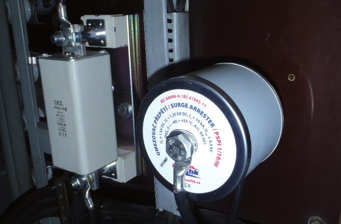
9 PSPI */10/III - OVERVOLTAGE LIMITERS - LINE DISCHARGE CLASS 3 Limiters for indoor use OVERVOLTAGE LIMITER PSPI */10/III LINE DISCHARGE CLASS 3 DC NETWORKS PSPI */10/III - OVERVOLTAGE LIMITERS - LINE DISCHARGE CLASS 3 PSPI */10/III overvoltage limiters designed to protect converter stations and DC networks of electric traction systems linked to them from the effects of atmospheric and switching overvoltage. They are used for protecting traction lines, electrical equipments of trolleybuses and trams. They do not require any maintenance during their traffic lite. The PSPI */10/III series is intended for indoor applications. The functional part of the limiters consists of a column of varistors sized for continuous operating voltage U C ; the outer insulating shell is composed from silicon material (grey colour). The material of the shell shows high resistance to the effects of surface leakage currents and to electric arc, possesses hydrophobic properties and shows excellent resistance to weather effects, pollution and UV radiation. The cover caps, connecting screws, nuts and terminals are made of stainless steel. With their design and technical parameters, the overvoltage limiters of the PSPI series conform to the standards ČSN EN , IEC , ČSN EN and EN Technical data PSPI 1/10/III PSPI 1/10/III SL PSPI 2/10/III PSPI 3/10/III PSPI 4/10/III PSPI 5/10/III PSPI 6/10/III Continuous operating voltage (DC) U C (= U r ) * 1,25 kv 1 kv 2,5 kv 3,75 kv 4,2 kv 5,5 kv 6,7 kv Nominal discharge current I n 10 ka 10 ka 10 ka 10 ka 10 ka 10 ka 10 ka Use in power net 600/750 V 600/750 V 1500 V special application 3000 V special application special application High impulze current (4/10) 2 x 100 ka 2 x 70 ka 2 x 100 ka 2 x 100 ka 2 x 100 ka 2 x 100 ka 2 x 100 ka Long current impulse (2ms) 850 A 850 A 850 A 850 A 850 A 850 A 850 A Discharge class acc. to EN Residual voltage at I n U res 3,5 kv 2,5 kv 7 kv 10,5 kv 10,7 kv 14,2 kv 17,7 kv Height h 83 mm 83 mm 88 mm 106 mm 115 mm 123 mm 125 mm Operating temperature range -40 C + 55 C -40 C + 55 C -40 C + 55 C -40 C + 55 C -40 C + 55 C -40 C + 55 C -40 C + 55 C Weight m 1,5 kg 1,5 kg 1,6 kg 1,9 kg 2,1 kg 2,3 kg 2,6 kg Article number /SL * The rated voltage U r of the arrester coincides with the continuous operating voltage U c. Note: The height and weight are indicative only and may vary. We can send accurate dat. Transport and storage The overvoltage limiters may not be exposed to strong shocks and impacts during transport. They should be stored in the long term in an indoor store. Maintenance No testing of the function or maintenance such as cleaning is necessary during the anticipated life of the limiter. Advantages High absorption capacity Resistance to ageing Design resistant to explosion and bursting Resistance to pollution and UV radiation Resistance of the shell to rough handling Maintenance-free design Resistance to shocks and vibrations High mechanical resistance 9


10 PSP */20/IV - OVERVOLTAGE LIMITERS - LINE DISCHARGE CLASS 4 The limiters are suitable for both outdoor and indoor use OVERVOLTAGE LIMITER PSP */20/IV LINE DISCHARGE CLASS 4 DC NETWORKS PSP */20/IV - OVERVOLTAGE LIMITERS - LINE DISCHARGE CLASS 4 PSP */20/IV overvoltage limiters designed to protect converter stations and DC networks of electric traction systems linked to them from the effects of atmospheric and switching overvoltage. They are used for protecting traction lines, electrical equipments of trolleybuses and trams. They do not require any maintenance during their traffic lite. The PSP */20/IV series is intended for outdoor and indoor applications. The functional part of the limiters consists of a column of varistors sized for continuous operating voltage U C ; the outer insulating shell is composed from silicon material (grey colour). The material of the shell shows high resistance to the effects of surface leakage currents and to electric arc, possesses hydrophobic properties and shows excellent resistance to weather effects, pollution and UV radiation. The cover caps, connecting screws, nuts and terminals are made of stainless steel. With their design and technical parameters, the overvoltage limiters of the PSP series conform to the standards ČSN EN , IEC , ČSN EN and EN Technical data PSP 1/20/IV PSP 2/20/IV PSP 3/20/IV PSP 4/20/IV Continuous operating voltage (DC) U C (= U r ) * 1,2 kv 2,35 kv 3,5 kv 4,7 kv Nominal discharge current I n 20 ka 20 ka 20 ka 20 ka Use in power net 600/750 V 1500 V special application 3000 V High impulze current (4/10) 2 x 100 ka 2 x 100 ka 2 x 100 ka 2 x 100 ka Long current impulse (2ms) 1350 A 1350 A 1350 A 1350 A Discharge class acc. to EN Residual voltage at I n U res 3,1 kv 6,2 kv 9,3 kv 12,4 kv Height h 85 mm 102 mm 117 mm 134 mm Operating temperature range -40 C + 55 C -40 C + 55 C -40 C + 55 C -40 C + 55 C Weight m 2 kg 2,5 kg 3,1 kg 3,65 kg Article number *The rated voltage U r of the arrester coincides with the continuous operating voltage U c. Note: The height and weight are indicative only and may vary. We can send accurate dat. Transport and storage The overvoltage limiters may not be exposed to strong shocks and impacts during transport. They should be stored in the long term in an indoor store. Maintenance No testing of the function or maintenance such as cleaning is necessary during the anticipated life of the limiter. Advantages High absorption capacity Resistance to ageing Design resistant to explosion and bursting Resistance to pollution and UV radiation Resistance of the shell to rough handling Maintenance-free design Resistance to shocks and vibrations High mechanical resistance 10


11 PSPI */20/IV - OVERVOLTAGE LIMITERS - LINE DISCHARGE CLASS 4 Limiters for indoor use OVERVOLTAGE LIMITER PSPI */20/IV LINE DISCHARGE CLASS 4 DC NETWORKS PSPI */20/IV - OVERVOLTAGE LIMITERS - LINE DISCHARGE CLASS 4 PSPI */20/IV overvoltage limiters designed to protect converter stations and DC networks of electric traction systems linked to them from the effects of atmospheric and switching overvoltage. They are used for protecting traction lines, electrical equipments of trolleybuses and trams. They do not require any maintenance during their traffic lite. The PSPI */20/IV series is intended for indoor applications. The functional part of the limiters consists of a column of varistors sized for continuous operating voltage U C ; the outer insulating shell is composed from silicon material (grey colour). The material of the shell shows high resistance to the effects of surface leakage currents and to electric arc, possesses hydrophobic properties and shows excellent resistance to weather effects, pollution and UV radiation. The cover caps, connecting screws, nuts and terminals are made of stainless steel. With their design and technical parameters, the overvoltage limiters of the PSPI series conform to the standards ČSN EN , IEC , ČSN EN and EN Technical data PSPI 1/20/IV PSPI 2/20/IV PSPI 3/20/IV PSPI 4/20/IV PSPI 5/20/IV Continuous operating voltage (DC) U C (= U r ) * 1,2 kv 2,35 kv 3,5 kv 4,7 kv 5,85 kv Nominal discharge current I n 20 ka 20 ka 20 ka 20 ka 20 ka Use in power net 600/750 V 1500 V special application 3000 V special application High impulze current (4/10) 2 x 100 ka 2 x 100 ka 2 x 100 ka 2 x 100 ka 2 x 100 ka Long current impulse (2ms) 1350 A 1350 A 1350 A 1350 A 1350 A Discharge class acc. to EN Residual voltage at I n U res 3,1 kv 6,2 kv 9,3 kv 12,4 kv 15,5 kv Height h 85 mm 102 mm 117 mm 134 mm 151 mm Operating temperature range -40 C + 55 C -40 C + 55 C -40 C + 55 C -40 C + 55 C -40 C + 55 C Weight m 1,9 kg 2,3 kg 2,9 kg 3,4 kg 4 kg Article number *The rated voltage U r of the arrester coincides with the continuous operating voltage U c. Note: The height and weight are indicative only and may vary. We can send accurate dat. Transport and storage The overvoltage limiters may not be exposed to strong shocks and impacts during transport. They should be stored in the long term in an indoor store. Maintenance No testing of the function or maintenance such as cleaning is necessary during the anticipated life of the limiter. Advantages High absorption capacity Resistance to ageing Design resistant to explosion and bursting Resistance to pollution and UV radiation Resistance of the shell to rough handling Maintenance-free design Resistance to shocks and vibrations High mechanical resistance 11

.")
12 PSPI */10 - OVERVOLTAGE LIMITER - LINE DISCHARGE CLASS 1 Limiters for indoor use OVERVOLTAGE LIMITER PSPI */10 LINE DISCHARGE CLASS 1 AC NETWORKS PSPI */10 - OVERVOLTAGE LIMITER - LINE DISCHARGE CLASS 1 PSPI */10 is an overvoltage limiter designed for internal use to protect high-voltage transmission networks; transformers, switchgears, HV cable distribution systems and, in particular, cable heads of enclosed substations from the effects of atmospheric and switching overvoltage. The functional part of the limiters consists a column of varistors sized for max. continuous operating voltage U C, the outer insulating shell is made from silicon material (grey colour). The material of the shell shows high resistance to the effects of surface leakage currents and to electric arc, possesses hydrophobic properties and shows excellent resistance to weather effects, pollution and UV radiation. The cover caps, connecting screws, nuts and terminals are made of stainless steel. With their design and technical parameters, the overvoltage limiters of the PSPI series conform to the standards ČSN EN and IEC Technical data PSPI 0,280/10 PSPI 0,440/10 PSPI 0,8/10 PSPI 1/10 PSPI 1,6/10 Max. continuous operating voltage (AC) U C 0,28 kv 0,44 kv 0,8 kv 1 kv 1,6 kv Nominal voltage (AC) U r 0,33 kv 0,55 kv 1 kv 1,25 kv 2 kv Nominal discharge current I n 10 ka 10 ka 10 ka 10 ka 10 ka Max. discharge current (8/20) I max 40 ka 40 ka 40 ka 40 ka 40 ka Long current impulse (2ms) 300 A 300 A 300 A 300 A 300 A Discharge class acc. to EN Residual voltage at I n U res 1,25 kv 1,8 kv 3,3 kv 3,7 kv 5,5 kv Height h 65 mm 67 mm 69 mm 73 mm 75 mm Operating temperature range -40 C + 55 C -40 C + 55 C -40 C + 55 C -40 C + 55 C -40 C + 55 C Weight m 425 g 445 g 470 g 490 g 520 g Article number Note: The height and weight are indicative only and may vary. We can send accurate dat. Transport and storage The overvoltage limiters may not be exposed to strong shocks and impacts during transport. They should be stored in the long term in an indoor store. Maintenance No testing of the function or maintenance such as cleaning is necessary during the anticipated life of the limiter. Advantages High absorption capacity Resistance to ageing Design resistant to explosion and bursting Resistance to pollution and UV radiation Resistance of the shell to rough handling Maintenance-free design Resistance to shocks and vibrations High mechanical resistance 12


13 PSPN */10/III - OVERVOLTAGE LIMITER - LINE DISCHARGE CLASS 3 PSPN */10/III Limiters for indoor use OVERVOLTAGE LIMITER PSPN */10/III LINE DISCHARGE CLASS 3 AC NETWORKS PSPN 1/10/III to PSPN 3/10/III PSPN 4/10/III to PSPN 7/10/III TERMINATION KL TERMINATION KL PSPN */10/III - OVERVOLTAGE LIMITER - LINE DISCHARGE CLASS 3 CABLE LENGTH CABLE H07V-K, CYA 50 CABLE LENGTH CABLE H07V-K, CYA 50 PSPN */10/III is an overvoltage limiter designed for internal use to protect high-voltage transmission networks; transformers, switchgears, HV cable distribution systems and, in particular, cable heads of enclosed substations from the effects of atmospheric and switching overvoltage. The functional part of the limiters consists a column of varistors sized for max. continuous operating voltage U C, the outer insulating shell is made from silicon material (grey colour). The material of the shell shows high resistance to the effects of surface leakage currents and to electric arc, possesses hydrophobic properties and shows excellent resistance to weather effects, pollution and UV radiation. The cover caps, connecting screws, nuts and terminals are made of stainless steel. With their design and technical parameters, the overvoltage limiters of the PSPN series conform to the standards ČSN EN and IEC NUT M12 X 20 NUT M12 X 20 Standard cable length 0.5 metres. Other lengths are also possible at the customer s request. Technical data PSPN 1/10/III PSPN 2/10/III PSPN 3/10/III PSPN 4/10/III PSPN 5/10/III PSPN 6/10/III PSPN 7/10/III Max. continuous operating voltage (AC) U C 0,88 kv 1,75 kv 3 kv 3,9 kv 4,75 kv 6 kv 6,9 kv Nominal voltage (AC) U r 1,1 kv 2,2 kv 3,75 kv 4,8 kv 6 kv 7,5 kv 8,6 kv Nominal discharge current I n 10 ka 10 ka 10 ka 10 ka 10 ka 10 ka 10 ka High impulze current (4/10) 2 x 100 ka 2 x 100 ka 2 x 100 ka 2 x 100 ka 2 x 100 ka 2 x 100 ka 2 x 100 ka Long current impulse (2ms) 850 A 850 A 850 A 850 A 850 A 850 A 850 A Discharge class acc. to EN Residual voltage at I n U res 3,5 kv 7 kv 10,7 kv 14,5 kv 18,3 kv 21,4 kv 25 kv Height h 95 mm 95 mm 95 mm 130 mm 130 mm 130 mm 130 mm Operating temperature range -40 C + 55 C -40 C + 55 C -40 C + 55 C -40 C + 55 C -40 C + 55 C -40 C + 55 C -40 C + 55 C Weight m 1,6 kg 1,6 kg 1,6 kg 2,3 kg 2,3 kg 2,3 kg 2,3 kg Article number Note: The height and weight are indicative only and may vary. We can send accurate dat. Transport and storage The overvoltage limiters may not be exposed to strong shocks and impacts during transport. They should be stored in the long term in an indoor store. Maintenance No testing of the function or maintenance such as cleaning is necessary during the anticipated life of the limiter. Advantages High absorption capacity Resistance to ageing Design resistant to explosion and bursting Resistance to pollution and UV radiation Resistance of the shell to rough handling Maintenance-free design Resistance to shocks and vibrations High mechanical resistance 13

14 POWER SUPPLY SYSTEMS UP TO 1000V Protection Device TYPE 2 + TYPE 3 acc. to EN IP65 - CE Limiters for indoor use UNIVERSAL SURGE ARRESTER - AC NETWORK U N = VAC - DC NETWORK U N = VDC SPD17FM SPD510FM Standartní délka vodičů Standard 200mm lenght 200mm ((possible možnost another vlastní lenght délky on base na of request) vyžádání) SPD275FM is basic representative of a broad series of varistor surge protection devices TYPE 2 + 3, designed acc. to EN , EN , IEC and EN for general use in both AC and DC distribution networks. Can be applied without the use of DIN rails even in places where the confined installation space as well as an additional montage-action in applications where the overvoltage occurence during operation makes a problems. They have a high absorptive capacity. All models are equipped with two internal disconnecting contacts that are activated when built-in varistor is overheating above 136ºC. First internal disconnection contact serves for disconnection alternativelly overloaded varistor units, second internal disconnection contact is used for remote reporting of FAILURE status (Fail Monitoring). Form of connecting of SPD to given application is solved by cords in the length of 20cm. The efficiency of this additional protection is about 10 meters from the point of its application. This connecting is recommended to make as close to the protected line section or protected appliances. The customer has the possibility to specify in order a dimensioning of inbuilt varistor acc. kind of his application (Tab. 1 on the other side of this data sheet) for AC or DC system, also can specify the color of power terminals acc. to the connection method of the arrester to the protected network. According to this choice, it is then possible to apply the chosen type of SPD: FM max 230V/0,5A H07V-K 1,5 m (z/ž,č) TVB 0,35 (f) TVB 0,35 (f) H07V-K 1,5 č (r,m) 136 C VA - in the AC low-voltage distribution nets from 17 VAC to 510VAC between phase and neutral conductor, between phase and phase, between phase and neutral conductor or betwen neutral conductor and PE - in DC low voltage distribution nets from 22 VDC to 670VDC (for example data, communication, measurement and control lines) between + conductor and - conductor, between + conductor PE or between - conductor and PE TYPE SPD275FM Classification acc. to EN ed.2 and IEC TYPE Nominal operating voltage U N 230 VAC Max. continuous operating voltage U C 275 VAC Max. discharge current (8/20) I max 25 ka Nominal discharge current (8/20) I n 10 ka Combined impulse U OC < 10 kv Voltage protection level at I n U P < 1 kv Voltage protection level at U OC U P < 1,2 kv Response time t A < 25 nsec TOV endurability U T 335 V/5s Max. back-up fuse 25 A Failure monitoring by potential-free contact FM max. 230 VAC/0,5 A Life time min hod. Covering IP IP 65 Weight/dimensions m ca 30g / 43x32x22 mm Load lenght l 200 mm, wires 1,5 mm 2 and 0,35 mm 2 Operating position Article number arbitrary (see Tab. 1 item) 14
15 UNIVERSAL SURGE ARRESTER - AC NETWORK U N = VAC - DC NETWORK U N = VDC TAB. 1: SUMMARY OF PRODUCED TYPES TYPE Max. continuous operating Varistor voltage Clamping voltage Discharge current Measure limiting voltage Maximum voltage U C energy 10/1000 AC DC V 1mA V C at I P I n I max U P at I P µsec V V min max V A ka V ka J SPD17FM SPD20FM SPD25FM SPD30FM Article number SPD35FM SPD40FM SPD50FM SPD60FM SPD75FM SPD95FM SPD115FM SPD130FM SPD210FM SPD230FM SPD250FM SPD275FM SPD140FM SPD150FM SPD175FM SPD190FM SPD300FM SPD320FM SPD350FM SPD385FM SPD420FM SPD460FM SPD510FM Note. 1: Depending on the application, it is necessary in order to specify the exact size of max. continuous operating voltage UC according to Tab. 1, then the desired color of power outlets wires AC applications... colours...black/blue, black/black, black/green+yelow, blue/green+yelow DC applications... colours...red/blue, red/green+yelow, blue/green+yelow Note 2: Signalling failure (FM) wires are uniform with purple colours (all versions) Note 3: Example orders: SPD460FM, black/black... AC network U N = 3x400VAC, connection between phase and phase SPD275FM, black/blue...ac network U N = 1x230VAC, connection between phase and neutral SPD25FM, red/blue... DC network U N = 24V, connection between + conductor and - conductor SPD95FM, red/green+yelow... DC network U N = 110V, connection between + conductor and PE 15
16 LOW VOTAGE LIMITER FOR RAILWAY APPLICATIONS Voltage limiter device TYPE 1 (VLD-F) acc.to EN IP67 - CE Limiters for both outdoor and indoor use VOLTAGE LIMITER DEVICE TYPE 1, VLD-F APPLICATION IN AC AND DC TRACTION POWER SYSTEMS P120G, P60G P60G and P120G are a new types of low voltage limiters (voltage limiter devices type 1... VLD-F) based on requirements of EN , which are designed to protect the non-live parts of metallic structures in DC ev. AC traction power supply systems. They are used to effectively protect persons who may come into contact with these parts during lightning strikes or a defect of the tractive overhead line. The limiter has a high internal resistance when voltage on it is less than the nominal level its spark over voltage U VDC and becomes conductive when this level is exceeded. In case of failure arising from a contact between live parts of the power system and traction conductive portion unintentionally associated with return path limiter protects illegal contact voltage that becomes conductive and causes the power is turned off. According to EN , this type of limiter is recommended primarily for connection between the protected area and return circuit in overhead line areas (or pantograph areas) that may be in contact with live conductors or damaged current collector, then the support structures pylons which can become live due to a fault isolation. After re-applied voltage drops below of its nominal level spark over voltage U VDC the limiter returns to the non-conducting state again. 12,5 2x M12x20 51,5 112,5 170,5 3 12, Type P120G P60G Classification acc. EN and EN Type 1 (VLD-F) / Type 1 DC sparkover voltage U VDC 120V 60V Service life 5 operations 50/60Hz, 1sec 1 operation 50/60Hz, 0,5sec 1 operation 50/60Hz, 0,25sec, max. load 20 operations 8/20 µsec 1) 3 operations 10/350 µsec Functional part P120G (P60G) is made using a special gas-filled gas discharge tube (GDT) with shortened response time 20 nsec, rated for up to 3 consecutive strikes of lightning current 50kA (10/350). On the outer insulating cover is used a light blue silicone rubber. Working chamber of built GDT is equipped with technically sophisticated fail-save mode hardware that provides an automatically transition to short-circuit mode in the event of longtime overloads above 500A DC (AC) (this state is non-reversible). On the outer insulating cover is used a blue silicone rubber, which is hydrophobic and has excellent resistance against weathering, pollution and UV rays. Cover caps, connecting bolts and nuts are made from stainless steel, suitable for connection of conductors with cross section mm 2 Fe (Cu). The product is delivered with an integrated bracket, allowing direct mounting of P120G (P60G) to the protected metal structure (pillar, wall or flange). Recommended mounting position is vertical bracket up. Limiter is installed directly to a protected building construction (using two bolts M12), so that in the event of its activation was generated a conductive connection between this structure and the return path. The limiter can be activated either by lightning current ev. current resulting from contact protected metallic structure with a fallen overhead line. In such a case occurs between these parts of the occurrence of a potential difference of more than 120V (valid for P120G), ev. 60V (valid for P60G). Built-in GDT ignites instantly (response time is typically 20 nsec) and for a transitional period of both parts electrically interconnects (typical internal resistance initialized P120G (P60G) is 0,001 0,002 Ω). The duration of this transient process is automatically broken up by potential equalization between the protected structures and a return path, when it comes to an automatic switching off GDT due to recombination its gas filling. Advantages: I n I imp Impulse spark-over voltage at 1kV/µsec U res <800V <700V Protection level at I imp =50kA 2) U p <500V Fail-save reliability test 1 operation 50/60Hz, 120sec 100A Insulation resistance R isol >2GΩ at 50V >2GΩ at 25V Breakdown time 2) Covering IP 67 1) P60G and P120G limiters are maintenance free, have very little reaction time (<20nsec), high insulation resistance (> 2GΩ), high protective capacity and are equipped with fail-save hardware, which makes their diagnostic easy. They are resistant to harsh treatment, acid rain and mechanical damage. 2) To perform diagnostics it is recommended to use measuring instrument G-TESTER (supplier ACER VOLTAGE s. r. o.). This device allows to control the one hand, the DC spark over voltage (U VDC ) of the buit GDT, then the insulation resistance value R isol (from 25V DC up to 1000V DC ) A 200A 4kA 100kA 50kA <20nsec Operating temperatureteplota -40 to + 90 C Weight Encapsulation 580g silicon rubber Article number ) R izol >10 7 Ω after completion of loading sequence 2 ) Typical value
 designed for potential equalization on the installation")
17 POTENTIAL EQUALISATION ON METAL PARTS OF INDUSTRIAL TECHNOLOGY Power gas discharge tube LPZ 0 B 1 IP67 - CE Limiters for both outdoor and indoor use POTENTIAL EQUALISATION ON METAL PARTS OF INDUSTRIAL TECHNOLOGY PIPELINE, RAILWAY, TELECOMUNICATION P400G, P250G 2x M12x20 P400G and P250G are a power gas discharge tubes (GDT) designed for potential equalization on the installation components of buildings or technological units, which are not electrically connected to each other (according to EN ed. 2). It is recommended primarily for bridging of insulated flanges and insulated threaded joints in the pipeline cathodic protected parts of industrial technology. If between these parts arise some potential difference greater than its DC spark over voltage (U VDC ), GDT immediatelly ignited for a transitional period and both parth electrically interconnects (typical internal resistance initialized of inbuilt GDTs is 0,001 0,002 Ω). P400G (P250G) installation can be done both inside and outside buildings, in damp and underground spaces. P400G (P250G) functional part are made using a special gas discharge tube with shortened response time 20 nsec, designed for lightning current 100 ka (10/350). On the outer insulating cover is used a blue silicone rubber, which is hydrophobic and has excellent resistance against weathering, pollution and UV rays. Cover caps, connecting bolts and nuts are made from stainless steel, suitable for connection of conductors with cross section mm 2 Fe (Cu). The product is delivered with an integrated bracket, allowing direct mounting of P400G (P250G) to the protected metal structure (pillar, wall or flange). Recommended mounting position is vertical bracket up. 12,5 51, , Type P400G P250G Classification acc. EN a IEC Type 1 DC sparkover voltage U VDC 300V 500V 250V 300V Max. continuous operating voltage 50/60Hz U c 155V 125V Nominal discharge current (8/20) I n 100kA Impulse current(10/350) I imp 100kA -charge Q 50Asec -specific energy W/R 2500kJ/Ω Follow current interrupting rating at U c I fi 100A Protection level at I n and I imp 1) U p <1kV DC discharge current, 1 operation AC discharge current at 1200V (TOV)2),1 operation Advantages: 400A/0,5sec 300A/0,2sec Breakdown time 1) t A <20ns Insulation resistance at 100V DC R isol >1GΩ Covering Operation temperature 1) Products P400G (P250G) are maintenance-free, have very little reaction time (20nsec), high insulation resistance (> 1GΩ) and high protective ability. Next is this product resistant against to harsh treatment, acid rain and mechanical damage. 2) To perform diagnostics it is recommended to use measuring instrument G-TESTER (supplier ACER VOLTAGE s. r. o.). This device allows to control the one hand, the DC spark over voltage of the built GDT, then the value of the insulation resistance R isol (from 25V DC up to 1000V DC ). IP67-40 to +90 C Weight m 620g Encapsulation Life time silicon rubber min hod Article number ) Typical value 2) TOV Temporary over voltage 17
 designed for potential equalisation on the installation components of buildings or")
18 POTENTIAL EQUALISATION ON METAL PARTS OF INDUSTRIAL TECHNOLOGY Power gas discharge tube LPZ 0 B 1 IP67 - CE Limiters for both outdoor and indoor use POTENTIAL EQUALISATION ON METAL PARTS OF INDUSTRIAL TECHNOLOGY PIPELINE, RAILWAY, TELECOMUNICATION P600G 2x M12x20 P600G is a power gas discharge tube (GDT) designed for potential equalisation on the installation components of buildings or technological units, which are not electrically connected to each other (according to EN ed. 2). It is recommended primarily for bridging of insulated flanges and insulated threaded joints in the pipeline cathodic protected parts of industrial technology. If between these parts arise some potential difference greater than 600V, GDT immediatelly ignited for a transitional period and both parth electrically interconnects (typical internal resistance initialized P600G is 0,001 0,002 Ω). P600G installation can be done both inside and outside buildings, in damp and underground spaces. P600G functional part is made using a special gas dischage tube with shortened response time 20 nsec, designed for lightning current 100 ka (10/350). On the outer insulating cover is used a blue silicone rubber, which is hydrophobic and has excellent resistance against weathering, pollution and UV rays. Cover caps, connecting bolts and nuts are made from stainless steel, suitable for connection of conductors with cross section mm 2 Fe (Cu). The product is delivered with an integrated bracket, allowing direct mounting of P600G to the protected metal structure (pillar, wall or flange). Recommended mounting position is vertical bracket up. 12,5 51, , Type P600G Classification acc. EN a IEC Type 1 DC sparkover voltage U VDC 600V 1000V Max. continuous operating voltage 50/60Hz U c 255V Nominal discharge current (8/20) I n 100kA Impulse current(10/350) I imp 100kA -charge Q 50Asec -specific energy W/R 2500kJ/Ω Follow current interrupting rating at U c I fi 100A Protection level at I n and I imp 1) U p <1kV DC discharge current, 1 operation 400A/0,5sec AC discharge current at 1200V rms (TOV) 2), 1 operation 300A/0,2sec Breakdown time 1) t A <20ns Insulation resistance at 100V DC R isol >1GΩ Covering IP67 Operation temperature -40 to +90 C Weight m 620g Encapsulation silicone rubber Life time min hours Article number ) Typical value 2) TOV Temporary over voltage Advantages: 1) Product P600G is maintenance-free, has very little reaction time (20nsec), high insulation resistance (> 1GΩ) and high protective ability. Next is this product resistant against to harsh treatment, acid rain and mechanical damage. 2) To perform diagnostics it is recommended to use measuring instrument G-TESTER (supplier ACER VOLTAGE s. r. o.). This device allows to control the one hand, the DC spark over voltage of the built GDT, then the value of the insulation resistance R isol (from 25V DC up to 1000V DC ). 18


19 SURGE ARRESTER SPB */10 PP* On flat busbars - AC NETWORKS Arresters for both outdoor and indoor use NUT M8 fun type washer SURGE ARRESTER SPB */10 PP* LV POWER PROTECTION On flat busbars CABLE CSA [1000] SURGE ARRESTER SPB */10 PP* SPB is a surge arrester as per EN with a nominal discharge current of 10kA and a maximum continuous operating voltage of U C = 280V, 440V, 500V, 660V or 900V. They provide protection against low-voltage overvoltage, they protect in low-voltage overhead power distribution systems electrical equipment, instruments, switchgear of distribution transformers and reduce the risk of damage to in-house networks and their equipment by atmospheric and switching overvoltage in AC networks with a frequency of Hz. The SPB surge arresters protect against the destructive effects of lightning and switching overvoltage. It is recommended to use them in places secured against contact, e.g. by a position or barrier. The SPB surge arresters do not require any special maintenance, only a check after thunderstorms with atmospheric discharges. The destruction of arresters due to great overloading is indicated by the lifting-off of a red signalling cap. These arresters should be replaced by new ones. Considering the fact that an arrester is not destroyed in the event of its excessive overloading above guaranteed limits and subsequent thermal breakdown, this arrester can be mounted into switchboards directly on the buses of a power circuit-breaker. An SPB can be connected to all types of overhead conductor lines, including insulated lines to where it is supplied with an insulated piercing terminal. The connection with an insulated terminal makes it possible to connect a branch line to the protected structure and to mount and dismount the live arrester without the risk of contact with live parts under voltage. The SPBs are supplied in three basic modifications according to the method of mounting: SPB */10 PP * - on flat busbars in switchboards with a serrated lock washer and nut Technical data SPB 0,280/10 PP * SPB 0,440/10 PP * SPB 0,500/10 PP * SPB 0,660/10 PP * SPB 0,900/10 PP * Category tested in accordance with EN TYPE 2 Max. continuous operating voltage U C 280 V AC / 350 V DC 440 V AC / 585 V DC 500 V AC / 670 V DC 660 V AC / 895 V DC 900 V AC / 1200 V DC Nominal discharge current (8/20) I n 10 ka Max. discharge current (8/20) I max 40 ka Voltage protection level at I N U P < 1,25 kv < 1,8 kv < 2,2 kv < 2,5 kv < 3,6 kv Response time t A < 25 ns Operating temperature range -40 C + 80 C Operating position vertically with max. departure ± 45 C Covering IP65 Protection internal thermal disconnector Weight m 230 g 235 g 250 g 270 g 300 g * : conductor lenght and color Article number 100gy : 100cm, green-yellow č : 100cm, black gy : 80cm, green-yellow č : 80cm, black gy : 65cm, green-yellow č : 65cm, black


20 SURGE ARRESTER SPB */10 AlFe* On bare overhead conductors - AC NETWORKS Arresters for both outdoor and indoor use NUT M8 stainless cleat SURGE ARRESTER SPB */10 AlFe* LV POWER PROTECTION ON BARE OVERHEAD CONDUCTORS CABLE CSA [1000] SURGE ARRESTER SPB */10 AlFe* SPB is a surge arrester as per EN with a nominal discharge current of 10kA and a maximum continuous operating voltage of U C = 280V, 440V, 500V, 660V or 900V. They provide protection against low-voltage overvoltage, they protect in low-voltage overhead power distribution systems electrical equipment, instruments, switchgear of distribution transformers and reduce the risk of damage to in-house networks and their equipment by atmospheric and switching overvoltage in AC networks with a frequency of Hz. The SPB surge arresters protect against the destructive effects of lightning and switching overvoltage. It is recommended to use them in places secured against contact, e.g. by a position or barrier. The SPB surge arresters do not require any special maintenance, only a check after thunderstorms with atmospheric discharges. The destruction of arresters due to great overloading is indicated by the lifting-off of a red signalling cap. These arresters should be replaced by new ones. Considering the fact that an arrester is not destroyed in the event of its excessive overloading above guaranteed limits and subsequent thermal breakdown, this arrester can be mounted into switchboards directly on the buses of a power circuit-breaker. An SPB can be connected to all types of overhead conductor lines, including insulated lines to where it is supplied with an insulated piercing terminal. The connection with an insulated terminal makes it possible to connect a branch line to the protected structure and to mount and dismount the live arrester without the risk of contact with live parts under voltage. The SPBs are supplied in three basic modifications according to the method of mounting: SPB */10 AlFe * - on a bare AlFe conductor with a stinless clip and nut Technical data SPB 0,280/10 AlFe * SPB 0,440/10 AlFe * SPB 0,500/10 AlFe * SPB 0,660/10 AlFe * SPB 0,900/10 AlFe * Category tested in accordance with EN TYPE 2 Max. continuous operating voltage U C 280 V AC / 350 V DC 440 V AC / 585 V DC 500 V AC / 670 V DC 660 V AC / 895 V DC 900 V AC / 1200 V DC Nominal discharge current (8/20) I n 10 ka Max. discharge current (8/20) I max 40 ka Voltage protection level at I N U P < 1,25 kv < 1,8 kv < 2,2 kv < 2,5 kv < 3,6 kv Response time t A < 25 ns Operating temperature range -40 C + 80 C Operating position vertically with max. departure ± 45 C Covering IP65 Protection internal thermal disconnector Weight m 248 g 255 g 270 g 290 g 320 g * : conductor lenght and color Article number 100gy : 100cm, green-yellow č : 100cm, black gy : 80cm, green-yellow č : 80cm, black gy : 65cm, green-yellow č : 65cm, black


21 SURGE ARRESTER SPB */10 S* On insulated overhead conductors - AC NETWORKS Arresters for both outdoor and indoor use SURGE ARRESTER SPB */10 S* LV POWER PROTECTION ON INSULATED OVERHEAD CONDUCTORS s SURGE ARRESTER SPB */10 S* SPB is a surge arrester as per EN with a nominal discharge current of 10kA and a maximum continuous operating voltage of U C = 280V, 440V, 500V, 660V or 900V. They provide protection against low-voltage overvoltage, they protect in low-voltage overhead power distribution systems electrical equipment, instruments, switchgear of distribution transformers and reduce the risk of damage to in-house networks and their equipment by atmospheric and switching overvoltage in AC networks with a frequency of Hz. The SPB surge arresters protect against the destructive effects of lightning and switching overvoltage. It is recommended to use them in places secured against contact, e.g. by a position or barrier. The SPB surge arresters do not require any special maintenance, only a check after thunderstorms with atmospheric discharges. The destruction of arresters due to great overloading is indicated by the lifting-off of a red signalling cap. These arresters should be replaced by new ones. Considering the fact that an arrester is not destroyed in the event of its excessive overloading above guaranteed limits and subsequent thermal breakdown, this arrester can be mounted into switchboards directly on the buses of a power circuit-breaker. An SPB can be connected to all types of overhead conductor lines, including insulated lines to where it is supplied with an insulated piercing terminal. The connection with an insulated terminal makes it possible to connect a branch line to the protected structure and to mount and dismount the live arrester without the risk of contact with live parts under voltage. The SPBs are supplied in three basic modifications according to the method of mounting: SPB */10 S * - on an insulated line with an insulated terminal Technical data SPB 0,280/10 S * SPB 0,440/10 S * SPB 0,500/10 S * SPB 0,660/10 S * SPB 0,900/10 S * Category tested in accordance with EN TYPE 2 Max. continuous operating voltage U C 280 V AC / 350 V DC 440 V AC / 585 V DC 500 V AC / 670 V DC 660 V AC / 895 V DC 900 V AC / 1200 V DC Nominal discharge current (8/20) I n 10 ka Max. discharge current (8/20) I max 40 ka Voltage protection level at I N U P < 1,25 kv < 1,8 kv < 2,2 kv < 2,5 kv < 3,6 kv Response time t A < 25 ns Operating temperature range -40 C + 80 C Operating position vertically with max. departure ± 45 C Covering IP65 Protection internal thermal disconnector Weight m 337 g 345 g 370 g 390 g 420 g * : conductor lenght and color Article number 100gy : 100cm, green-yellow č : 100cm, black gy : 80cm, green-yellow č : 80cm, black gy : 65cm, green-yellow č : 65cm, black
22 Characteristics and performance Predominantly capacitative current in the order of hundreds of µa passes through the surge arrester at continuous operating voltage. The active component of the current is negligible. When the terminal voltage of the surge arrester increases, the surge arrester changes smoothly to an on-state and limits all types of overvoltage. The response time is very small (in the order of 100 ns) so the surge arrester reliably limits even steep surges of atmospheric overvoltage. The surge arrester consists of a plastic housing with connecting leads, a separately enclosed watertight and electrically isolated varistor encapsulated in silicon caoutchouk, thermal disconnector and a signalling cap in the bottom part of the housing. Easy assembly is an advantage as well. The plastic of the housing is resistant to UV radiation, weather effects and is flame-retardant Class V0. The connecting screws and terminals are made of stainless steel. The surge arrester is fitted with an earthing cable with an end green-yellow or black in colour as required by the customer, with a length of 0.65 m, 0.8 m or 1.0 m, or with other lengths as agreed with the customer. The built-in disconnector is used to disconnect the limiter from the mains in the event of its overloading, which may occur owing to the limit parameters of the varistor being exceeded (absorption of greater energy, e.g. due to a long-term increase in the operating voltage above Uc, or due to great voltage induced by a lightning strike in the immediate vicinity). The maximum current of the varistor is 100 ka, 4/10 μs. In the event of two consecutive pulses of 65 ka, 4/10 μs, the varistor temperature may reach a value at which the disconnector gets disconnected.. Disconnection is signalled in such a way that the red cap of the surge arrester in the bottom SURGE ARRESTER SPB */10 PP; AlFe; S LV POWER PROTECTION part of the housing is lifted off. In the event of varistor breakdown (e.g. when the maximum current is exceeded owing to a steep pulse), the enclosed varistor may be carried up from the housing by short-circuit current without the outer shell of the surge arrester being damaged or destroyed. This will ensure that the surge arrester is disconnected from the mains without potential damage to surrounding objects (except the bottom part) or a flashover between busbars in the switchgear. The disconnection is again indicated by the lifting off of the cap. When an insulated terminal is used, all the live parts remain sufficiently insulated and protected against accidental contact. Operation Failure Disconnection is signalled in such a way that the red cap of the limiter in the bottom part of the housing is lifted off. Transport, handling and storage requirements The surge arresters shall be packed individually in a polyethylene bag and transported in non-returnable cardboard boxes. Other packaging is possible by agreement with the customer. The surge arresters shall be stored in cartons in indoor closed stores at a temperature from 30 C to +30 C. Foam or water may be used as extinguishing agents. During transport it is necessary to handle the product with care so as not to damage the carton packaging. Effect on the environment There is no risk of a negative influence on the environment during the transport, handling, storage and use of the product. The disposal of damaged products shall be carried out by taking them to a waste dump. The waste catalogue number is
23 Notes 23


24 Reference Photo of installation 24
surge arresters overvoltage limiters Low voltage limiters catalogue 2017
 catalogue 2017 surge arresters overvoltage limiters Low voltage limiters CONTENT OF THE CATALOGUE COMPANY PROFILE ACER VOLTAGE 2 OVERVOLTAGE DEFINITIONS, OVERVOLTAGE LIMITERS ZnO 3 DIMENSIONING OF OVERVOLTAGE
Voltage limiting device HVL
 Datasheet Voltage limiting device HVL 120-0.3 1 2 3 3 Equivalent circuit of voltage limiting device Type HVL 120-0.3 1 MO-surge arrester 2 Trigger electronics 3 Thyristor Product Description The HVL 120-0.3
Voltage limiting device HVL
 Datasheet Voltage limiting device HVL 60-0.3 1 2 3 3 Equivalent circuit of voltage limiting device Type HVL 60-0.3 1 MO-surge arrester 2 Trigger electronics 3 Thyristor Product Description The HVL 60-0.3
CONTENTS About the company 1. Low-voltage arresters LVA type 2. Metal-oxide surge arresters for distribution systems. 3.
 CONTENTS About the company 4 1. Low-voltage arresters LVA type 5 2. Metal-oxide surge arresters for distribution systems. 6 2.1 PA-DM type 6 Dimensions of arresters of PA-DM 9 2.2 PA-DH types 10 Dimensions
MEDIUM VOLTAGE NETWORKS
 MEDIUM VOLTAGE NETWORKS LIGHTNING ARRESTERS & INSULATORS SICAME GROUP OUR EXPERIENCE With 25 years of experience in the field of over protection for medium lines, DERVASIL designs and manufactures zinc
INTRODUCTION. The plug-in connection on the cables and lightning arrestors, allows for easy installation and replacement.
 INTRODUCTION The Power Systems 44 kv MiniSub TM is the most compact system at this voltage available. Utilizing a deadfront termination and lightning arrestor setup, it eliminates the line top or side
Surge arrester POLIM-H.. ND
 DATA SHEET Surge arrester POLIM-H.. ND Technical data Classification according to EN 50526-1 and IEC 62848-1 Nominal discharge current I n (8/20 µs) 10 ka peak Class DC-B High current impulse I hc (4/10
Independent Testing Laboratory for High Voltage Equipment
 T E S T I N G L A B O R A T O R Y Independent Testing Laboratory for High Voltage Equipment 1 CHALLENGING ENVIRONMENT The primary concern for utilities is to ensure grid reliability, efficiency, and security.
SLOVAK UNIVERSITY OF TECHNOLOGY Faculty of Material Science and Technology in Trnava ELECTRICAL ENGINEERING AND ELECTRONICS.
 SLOVAK UNIVERSITY OF TECHNOLOGY Faculty of Material Science and Technology in Trnava ELECTRICAL ENGINEERING AND ELECTRONICS Róbert Riedlmajer TRNAVA 2007 Unit 14 - Fundamentals of power system protection
3EQ Composite Housed Surge Arresters Saving Money and Space, Gaining Reliability
 3EQ Composite Housed Surge Arresters Saving Money and Space, Gaining Reliability Power Transmission and Distribution 1 A perfect Combination of Cost-Savings, Safety and Reliability 3EQ Surge Arresters:
Surge arrester POLIM-H..SD
 Data sheet Surge arrester POLIM-H..SD Technical data Classification according to EN 50526-1 and IEC 62848-1 Nominal discharge current I n (8/20 µs) 10 ka peak Class DC-B High current impulse I hc (4/10
HIGH VOLTAGE SURGE ARRESTER SPECIFICATION
 HIGH VOLTAGE SURGE ARRESTER SPECIFICATION Applications: (Polymer housed MOA for 110kv) (The polymer housed MOA for 10kv) (Porcelain housed MOA for 220kv) (35kv MOA without gaps for middle phase) (110kv
Energy Division. PCA Single Column Polymeric Surge Arrester
 Energy Division PCA Single Column Polymeric Surge Arrester Bowthorpe EMP pioneered the development of the polymeric composite housed surge arrester in the early 1980 s and since 1986 has a proven service
Zinc Oxide Surge Arrester EXLIM R
 Zinc Oxide Surge Arrester EXLIM R Protection of switchgear, transformers and other equipment in high systems against atmospheric and switching overs. For use when requirements of lightning intensity, energy
ABB Switzerland Ltd Phone Surge arresters Telefax:
 Operating Manual Publication number 1HC0023892 Low Voltage Limiter Type HVL 120-0.3 With metal oxide varistor and thyristors from ABB Silicon housing material for indoor and outdoor applications Transport,
Surge arrester POLIM-C.. HD
 DATA SHEET Surge arrester POLIM-C.. HD Technical data Classification according to EN 50526-1 and IEC 62848-1 Nominal discharge current I n (8/20 µs) 10 ka peak Class DC-A High current impulse I hc (4/10
3EP1 Surge Arrester. Metal-oxide surge arrester without series gaps for high-voltage systems up to U m. = 170 kv
 3EP1 Surge Arrester Metal-oxide surge arrester without series gaps for high-voltage systems up to U m = 170 kv Rated voltage up to 180 kv Nominal discharge current 10 ka, 8/20 µs Line discharge class LD1,
3EQ Composite Housed Surge Arresters
 Power Transmission and Distribution 3EQ Composite Housed Surge Arresters Saving Money and Space, Gaining Reliability A perfect Combination of Cost-Savings, Safety and Reliability 3EQ Surge Arresters: Your
Surge Arresters. UltraSIL Housed VariSTAR Station Class Surge Arresters GENERAL CONSTRUCTION
 Surge Arresters UltraSIL Housed VariSTAR Station Class Surge Arresters Electrical Apparatus 235-88 GENERAL Cooper Power Systems has set a new standard of excellence for polymerhoused station class surge
Type HS PEXLIM-P Surge Arresters Maximum System Voltage 123 kv to 800 kv
 Type HS PEXLIM-P Surge Arresters Maximum System Voltage 123 kv to 800 kv HS PEXLIM-P Metal Oxide Surge Arrester HS PEXLIM-P Surge Arresters are used for the protection of switchgear, transformers and other
Directly Molded Polymer Surge Arresters
 Directly Molded Polymer Surge Arresters Ideal means to reduce environmental impact Up to 420kV, Comply with IEC60099-4, Line discharge class 2-4 l Long-life performance (Hydrophobic silicone rubber) l
3EK7 Medium Voltage Silicone Insulated Surge Arresters
 3EK7 Medium Voltage Silicone Insulated Surge Arresters Power Transmission and Distribution Setting new Standards The 3EK7 s mechanical features: Glass-collared MOV, Silicone rubber housing, FRP rods and
Medium-voltage fuses 3 kv 40.5 kv, 0.4 A 315 A
 DISTRIBUTION SOLUTIONS Medium-voltage fuses 3 kv 40.5 kv, 0.4 A 315 A Continuous protection and reliable operation Proven design and compliance with newest fuses standards Compatibility with other ABB
KEWTECH. KT56 digital multi function tester. Instruction manual
 KEWTECH KT56 digital multi function tester Instruction manual Contents 1 Safety Notice 1 2 Features and Principles of Measurement 3 3 Introduction 6 4 Specifications 7 5 Instrument layout 9 6 Operating
Surge-Trap Pluggable STPT2 Series - 40kA
 Surge-Trap Pluggable STPT2 Series - 40kA SURGE PROTECTION FOR POWER LINES DIN-RAIL IEC TYPE 2 / CLASS II FEATURES & BENEFITS Maximum discharge current (8/20μs): 40kA per phase Nominal discharge current
High Voltage Surge Arresters Station Class
 Power Transmission and Distribution High Voltage Surge Arresters Station Class Product Overview High Voltage High Protection Just as the Golden Gate Bridge has successfully defied all winds, weather and
LIGHTNING EQUIPOTENTIAL BONDING ISOLATING SPARK GAPS. EXFS L / EXFS KU for explosive Areas
 EXFS L / for explosive Areas For indirect connection/earthing of functionally separate system parts at lightning strikes Unit for lightning equipotential bonding according to IEC 61024-1 for hazardous
FUSES. Safety through quality
 Safety through quality HH HIGH VOLTAGE Over many decades SIBA has developed a global product line of High Voltage Fuses that are comprehensive for any and all applications. Superior engineering, advanced
Type SIMOPRIME A4, up to 24 kv, Air-Insulated Medium-Voltage Switchgear
 Circuit-Breaker www.siemens.com/energy Switchgear Type SIMOPRIME A4, up to 24 kv, Air-Insulated Medium-Voltage Switchgear s Technology Circuit-Breaker Switchgear Type SIMOPRIME, up to 17.5 kv, Air-Insulated
3EK7 Distribution Class Surge Arresters. Answers for energy.
 3EK7 Distribution Class Surge Arresters Answers for energy. Siemens at Your Service As a global leader of the electronics industries, Siemens has been active in the fields of power transmission and distribution
LED Driver Linear / area fixed output
 Driver LC 65W 4-7mA flexc lp ANCED series Product description Built-in constant current LED Driver Adjustable output current between 4 and 7 ma Max. output power 65 W Up to 94 % efficiency Nominal life-time
VariSTAR Type AZE station-class surge arresters for systems through 345 kv IEEE certified
 Surge s Catalog Data CA235022EN Supersedes TD235009EN September 2014 COOPER POWER SERIES VariSTAR Type AZE station-class surge arresters for systems through 345 kv IEEE certified General Eaton s Cooper
Surge arresters Product overview
 Surge arresters Product overview abb Surge arresters from ABB Switzerland ABB Switzerland Ltd has been developing and manufacturing for over a century, metal-oxide (MO) resistors and MO arresters for worldwide
Bowthorpe EMP LV/MV Outdoor Surge Arresters
 Bowthorpe EMP LV/MV Outdoor Surge Arresters Bowthorpe EMP LV/MV Surge Arresters for Outdoor Applications Table of Contents Product Classification Voltage Range Page DA Series Distribution Metal Oxide Surge
THP145 HYBRID GAS INSULATED SWITCHGEAR (HGIS) Energy, Fast! tgood.com
 Energy, Fast! tgood.com") THP145 HYBRID GAS INSULATED SWITCHGEAR (HGIS) Energy, Fast! tgood.com TGOOD produces over 5000 switchgear units annually for projects around the globe SOLUTION OVERVIEW For use in affordable air insulated
THP145 HYBRID GAS INSULATED SWITCHGEAR (HGIS) Energy, Fast! tgood.com TGOOD produces over 5000 switchgear units annually for projects around the globe SOLUTION OVERVIEW For use in affordable air insulated
Surge Arrester 3EL2 superior protection up to 550 kv
 Certified according to IEC 60099-4 Edition 2.1 (2006) Surge Arrester 3EL2 superior protection up to 550 Light weight. Strong performance. Answers for energy. Simply irresistible. By resisting wear in any
GUIDELINES ON ELECTRICAL SAFETY AT WORKPLACES
 MINISTRY OF LABOUR, INDUSTRIAL RELATIONS AND EMPLOYMENT GUIDELINES ON ELECTRICAL SAFETY AT WORKPLACES Occupational Safety & Health Inspectorate These guidelines should be used with approved standards:
Earthing Principles. Symmetra PX 250/500 kw
 Earthing Principles Symmetra PX 250/500 kw Table of Contents Earthing Principles... 1 Decoding the Earthing Types... 1 TN Systems... 2 Characteristics... 2 Reference to IEC/EN 60364-4-41 413.1.3... 2
Range 16A to 63A. Sensitivity 30mA, 100mA, 300mA, 500mA. Execution Double Pole, Four Pole. Specification IEC / IS : 2000
 The flow of current through electrical facilities always involves risks. Poorly insulated equipment, faulty wires and incorrect use of an electrical devise cause currents to flow through the wrong path
IEC Low Voltage General Purpose Protection
 , 6A, 0/400VAC (/440VAC) Complying with DIN VDE 0660 Part 07 EN / IEC 60947- DIN VDE 066 Part IEC 6069- DIN VDE 068 DIN VDE 4880 The D0-LINOCUR is a combination of switch-disconnector-fuse and NEOZED 6
RESIDUAL CURRENT CIRCUIT BREAKER
 Quality Features Mid Trip - Different knob position to indicate whether the device is Switched OFF by a fault or Switched OFF manually Inscription Window - Ensures circuit identification and hence reduces
020: 2013 CEB SPECIFICATION MINIATURE CIRCUIT BREAKER (MCB)
") 020: 2013 CEB SPECIFICATION MINIATURE CIRCUIT BREAKER (MCB) CEYLON ELECTRICITY BOARD SRI LANKA Telephone: +94 11 232 0953 Fax: +94 11 232 3935 CONTENTS Page 1.0 Scope 3 2.0 System Parameters 3 3.0 Service
020: 2013 CEB SPECIFICATION MINIATURE CIRCUIT BREAKER (MCB) CEYLON ELECTRICITY BOARD SRI LANKA Telephone: +94 11 232 0953 Fax: +94 11 232 3935 CONTENTS Page 1.0 Scope 3 2.0 System Parameters 3 3.0 Service
power pazifik Metal Oxide Surge Arrester with composite polymer insulator Type series SBK-I to IV /10.3
 Manufactured by: Metal Oxide Surge Arrester with composite polymer insulator Type series SBK-I to IV-6... 150/10.3 BT-A3/8 Surge Arresters housed in polymer housing, developed to protect switchgear, over
CPG.1 Gas insulated, single busbar cubicle range Up to 27 kv / 2000 A / 31.5 ka Up to 38 kv / 2000 A / 31.5 ka IEEE Standards
 Medium Voltage Switchgear Primary Distribution CPG.1 Gas insulated, single busbar cubicle range Up to 27 kv / 2000 A / 31.5 ka General description Presentation Ormazabal s CPG System includes the CPG.1
NFC. (Varistor Type NFC)
") NFC (Varistor Type NFC) Type NFC Varistors are made of semiconductor ceramic materials composed mainly of zinc oxide. They have nonlinear resistance that changes as a function of applied voltage. It has
NFC (Varistor Type NFC) Type NFC Varistors are made of semiconductor ceramic materials composed mainly of zinc oxide. They have nonlinear resistance that changes as a function of applied voltage. It has
Zinc-Oxide Surge Arrester TEXLIM Q-C
 Zinc-Oxide Surge Arrester TEXLIM Q-C Protection of switchgear, transformers and other equipment in high systems against atmospheric and switching overs. in areas with very high lightning intensity where
High Voltage Surge Arresters Buyer s Guide Section Transmission Line Arrester PEXLINK
 High Voltage Surge Arresters Buyer s Guide Section Transmission Line Arrester PEXLINK Definitions Transmission Line Arresters Backflashover Occurs when lightning strikes the tower structure or overhead
The University of New South Wales. School of Electrical Engineering and Telecommunications. Industrial and Commercial Power Systems Topic 2
 The University of New South Wales School of Electrical Engineering and Telecommunications Industrial and Commercial Power Systems Topic 2 SWITCHBOARDS Overview Also called Switchgear and Controlgear Assembly
Medium voltage fuses - European Fuses
 HV Back-up Fuse-Links according to IEC 60 282- HV fuse-links have been used for reliable protection in medium-voltage switchgear and controlgear and systems for decades. They protect apparatus and equipment
3EK7 Distribution Class Surge Arresters. Answers for energy.
 3EK7 Distribution Class Surge Arresters Answers for energy. Siemens at Your Service As a global leader of the electronics industries, Siemens has been active in the fields of power transmission and distribution
I Surge Arresters. UltraSIL Polymer-Housed VariSTAR Type U3 Surge Arrester for Systems through 275 kv IEC 10 ka; Line Discharge Class 3 GENERAL
 Surge Arresters UltraSIL Polymer-Housed VariSTAR Type U3 Surge Arrester for Systems through 275 kv IEC 10 ka; Line Discharge Class 3 Electrical Apparatus I235-93 GENERAL UltraSIL Polymer-Housed VariSTAR
Surge arresters for railway applications. Product guide. Siemens HP-AR 41. siemens.com/arresters
 Surge arresters for railway applications Product guide HP-AR 41 Siemens 2017 siemens.com/arresters Siemens surge arresters for railway applications reliable, stable and safe over protection electrification.
Surge Arresters. Supply Program. Answers for energy.
 Surge Arresters Supply Program www.siemens.com/energy/arrester Answers for energy. Always the Best Solution We offer an extensive range of surge arresters suitable for every application economical and
Type POLIM-S Surge Arresters Maximum System Voltage 2.52 to 245 kv
 Type POLIM-S Surge Arresters Maximum System Voltage 2.52 to 245 kv POLIM-S Metal Oxide Gapless Surge Arresters POLIM-S Surge Arresters are used for the protection of switchgear, transformers and other
Zinc Oxide Surge Arrester PEXLIM Q
 Zinc Oxide Surge Arrester Protection of switchgear, transformers and other equipment in high voltage systems against atmospheric and switching overvoltages. in areas with high lightning intensity and high
Electronic Ballast EVG 2000-T
 Electronic Ballast EVG 2000-T Operating Manual Table of contents 1 Description 1.1 Advantages of this ballast... 3 1.2 Functional principle... 3 1.3 Energization... 4 1.4 Visualization... 5 1.5 Indications
power cable accessories
 power cable accessories kv up to 4 kv Completing the picture based on experience is the future nkt cables GmbH NKT was established in 89 as cable manufacturer. In 999 NKT A/S Denmark merged with Felten
045 : 2000 CEB STANDARD
 045 : 2000 CEB STANDARD LOW VOLTAGE FUSE SWITCH DISCONNECTOR CEYLON ELECTRICITY BOARD SRI LANKA Specification for LOW VOLTAGE FUSE SWITCH DISCONNECTOR CEB Standard 045 : 2000 CEYLON ELECTRICITY BOARD No.
1489-M Circuit Breakers
 Dual terminals provide wiring/bus bar flexibility and clamp from both sides to improve connection reliability Terminal design helps prevent wiring misses Scratch- and solventresistant printing Suitable
ATyS S - ATyS d S Remotely operated Transfer Switching Equipment from 40 to 125 A
 Transfer switches The solution for > Genset < 90 kva > Heating systems > Climate control > Ventilation systems > Telecommunications atys-s_018_a Strong points Function products are 4 pole remotely operated
Overview Overvoltage protection
 A P P L I C AT I O N N OT E 1.0 Overview Overvoltage protection The APPLICATION NOTES (AN) are intended to be used in conjunction with the APPLICATION GUIDELINES Overvoltage protection Metal-oxide surge
Key elements of the AS3000 Wiring standards and some of the recent changes.
 Key elements of the AS3000 Wiring standards and some of the recent changes. Dean of Engineering Steve Mackay Worked for 30 years in Industrial Automation 30 years experience in mining, oil and gas, electrical
Medium voltage products. Fuses
 Medium voltage products Fuses Index Introduction... 3 Main definitions... 4 ABB HV Fuses with Temperature Control Unit... 5 General principles for fuse link selection... 6 CEF... 8 CEF-S... 16 CEF-VT...
Product presentation CPT tech Jason Evershed, ABB Transformer Components, May 21st Dry-type transformers Innovative Technology
 Product presentation CPT tech Jason Evershed, ABB Transformer Components, May 21st 2014 Dry-type transformers Innovative Technology What is a dry transformer? ABB manufactures a transformer which does
Domae. The right solution for distribution boards
 Domae The right solution for distribution boards Guaranteed quality and adapted solutions Domae : SIRIM approved The quality marks prove product conformity to their reference standard. They guarantee:
Soft Starter. Types RSBD. Product Description. Type Selection. Ordering Code RSB D E V 61 HP
 Soft Starter Three-Phase Scroll Compressor Soft Starter Types RSBD Soft starting of 3-phase scroll compressors up to 95Amp Patented auto-adaptive algorithm for optimum inrush current reduction (No user
Transformer bushings, type GOH. Technical guide
 Transformer bushings, type GOH Technical guide This Technical Guide has been produced to allow transformer manufacturers, and their designers and engineers, access to all the technical information required
Functions provided by measuring relays in railway equipment
 Functions provided by measuring relays in railway equipment 1-Current relays -Minimum current relays (During normal operation, if the current is present these relays are in operating position and switch
Miniature Circuit-Breakers (MCBs)
") Product Overview Miniature Circuit-Breakers (MCBs) Design Tripping characteristics Rated current I n Rated breaking capacity Power supply company product range 5SP3 E 16 - A Standard product range 5SQ2
Product Overview Miniature Circuit-Breakers (MCBs) Design Tripping characteristics Rated current I n Rated breaking capacity Power supply company product range 5SP3 E 16 - A Standard product range 5SQ2
LED Driver Linear / area dimming industry. Driver LC 150W mA IND sl EXC EXCITE series
 Driver LC 150W 200 1050mA IND sl EXC EXCITE series Product description Constant current built-in Driver for LED, particularly suitable for industrial applications in tough environments such as cold warehouses
Characteristics of LV circuit breakers Releases, tripping curves, and limitation
 Characteristics of LV circuit breakers Releases, tripping curves, and limitation Make, Withstand & Break Currents A circuit breaker is both a circuit-breaking device that can make, withstand and break
LED Driver Linear / area fixed output industry. Driver LCI 100W 350mA 900mA TOP INDUSTRY sl TOP series
 Driver LCI 100W 350mA 900mA TOP INDUSTRY sl TOP series Product description Fixed output constant current built-in LED Driver, particularly suitable for industrial applications in tough enviromments such
SD, SE, SDE, SCO series Multipole switchgear for rail vehicles: Disconnecting switches, Earthing Switches, Disconnector with Earthing Switches,
 4 Electrics for Rolling Stock Multipole switchgear for rail vehicles: Disconnecting switches, Earthing Switches, Disconnector with Earthing Switches, Change-Over-Switches 600 V to 3 kv Catalogue F84.en
Title High Voltage and 1500 System Earthing References and Definitions. Reference Number PDS 02 (RIC Standard: EP SP)
") Discipline Engineering Standard NSW Category Electrical Title High Voltage and 1500 System Earthing References and Definitions Reference Number PDS 02 (RIC Standard: EP 12 00 00 01 SP) Document Control
Discipline Engineering Standard NSW Category Electrical Title High Voltage and 1500 System Earthing References and Definitions Reference Number PDS 02 (RIC Standard: EP 12 00 00 01 SP) Document Control
BOWTHORPE EMP MEH SURGE ARRESTERS (IEC) ENERGY /// MEH SURGE ARRESTERS IEC
 ENERGY /// MEH SURGE ARRESTERS IEC") BOWTHORPE EMP MEH SURGE ARRESTERS (IEC) GENERIC TECHNICAL DATA Maximum system voltage U m 800 System voltage U s 750 Nominal discharge current ka 20 High current impulse (4/10 µs) ka 100 Arrester class
BOWTHORPE EMP MEH SURGE ARRESTERS (IEC) GENERIC TECHNICAL DATA Maximum system voltage U m 800 System voltage U s 750 Nominal discharge current ka 20 High current impulse (4/10 µs) ka 100 Arrester class
3NP1 Fuse Switch Disconnectors up to 630 A
 Switch Disconnectors 3NP1 Fuse Switch Disconnectors up to 630 A Introduction Overview All key product features at a glance available for all sizes Connection of circular conductors and laminated conductors
MEDIUM VOLTAGE PRODUCTS. Fault Current Limiters I S. -limiter and FC-Protector The worldʼs fastest switching devices
 MEDIUM VOLTAGE PRODUCTS The worldʼs fastest switching devices 2 FAULT CURRENT LIMITERS THE WORLDʼ S FASTETST SWITCHING DEVICES The worldʼs fastest switching devices ABBʼs fault current limiters disconnect
Fuse-links type CEF-VT Rated voltages 3/7.2 kv - 10/24 kv Rated current 0.5 A 6.3 A
 DISTRIBUTION SOLUTIONS Fuse-links type CEF-VT Rated voltages 3/7.2 kv - 10/24 kv Rated current 0.5 A 6.3 A Efficient protection of voltage transformer circuits Extending the lifetime of installed electrical
Switchgear Type 8BT1, up to 24 kv, air-insulated. Medium Voltage Switchgear Catalog HA 26.
 www.siemens.com/medium-voltage-switchgear Switchgear Type 8BT1, up to 24 kv, air-insulated Medium Voltage Switchgear Catalog HA 26.31 2012 Answers for infrastructure and cities. R-HA26-013. eps Contents
CPG.0 Single busbar gas-insulated cubicles
 MV Switchgear Primary Distribution CPG.0 Single busbar gas-insulated cubicles Up to 36 kv CPG System The quality of products designed, manufactured and installed by Ormazabal is underpinned by the implementation
Effective discrimination of protective devices
 Effective discrimination of protective devices In the event of a fault occurring on an electrical installation only the protective device nearest to the fault should operate,leaving other healthy circuits
Catalog HA Edition up to 24 kv, Air-Insulated, Extendable. Medium-Voltage Switchgear. siemens.com/simosec
 Catalog HA 41.43 Edition 2018 Switchgear Type SIMOSEC, up to 24 kv, Air-Insulated, Extendable Medium-Voltage Switchgear siemens.com/simosec Application Typical uses R-HA41-135.tif R-HA40-112.tif R-HA41-115.tif
DATASHEET - DILMC9-10(24VDC) Technical data General. Contactor, 3p+1N/O, 4kW/400V/AC3. Catalog No Eaton Catalog No. XTCEC009B10TD.
 Technical data General. Contactor, 3p+1N/O, 4kW/400V/AC3. Catalog No Eaton Catalog No. XTCEC009B10TD.") DATASHEET - DILMC9-10(24VDC) Technical data General Contactor, 3p+1N/O, 4kW/400V/AC3 Part no. DILMC9-10(24VDC) Catalog No. 277468 Eaton Catalog No. XTCEC009B10TD EL-Nummer 4110305 (Norway) Standards IEC/EN
DATASHEET - DILMC9-10(24VDC) Technical data General Contactor, 3p+1N/O, 4kW/400V/AC3 Part no. DILMC9-10(24VDC) Catalog No. 277468 Eaton Catalog No. XTCEC009B10TD EL-Nummer 4110305 (Norway) Standards IEC/EN
HHD HIGH VOLTAGE FUSES GERMAN DIN STANDARD. The temperature limiting function of the fuse striker pin. Design and construction.
 HHD HIGH VOLTAGE GERMAN DIN STANDARD FOR AIR & GAS INSULATED SWITCHGEARS OUTDOOR SWITCHGEARS The striker pin system is connected by means of a high resistance parallel conductor. After melting the main
LED Driver Linear / area fixed output industry. Driver LCI 65W 150mA 400mA TOP INDUSTRY sl TOP series
 Driver LCI 65W 150mA 400mA TOP INDUSTRY sl TOP series Product description Fixed output constant current built-in LED Driver, particularly suitable for industrial applications in tough enviromments such
Circuit-Breaker Switchgear Type SIMOPRIME, up to 17.5 kv, Air-Insulated Medium-Voltage Switchgear.
 Circuit-Breaker Switchgear Type SIMOPRIME, up to 17.5 kv, Air-Insulated Medium-Voltage Switchgear www.siemens.com/energy Technology s Contents Application Page Benefits 2 Typical uses 2 and 3 Technical
Contactors. CH1130/02 Series Single pole high-voltage contactor up to 3 kv Catalogue C170.en. Connect - Contact - Control
 Connect - Contact - Control 3 Contactors CH1130/02 Series Single pole high-voltage contactor up to 3 kv Catalogue C170.en More information at: schaltbau-gmbh.com 42 CH1130/02 Single pole high-voltage contactor
Fuse-links type CEF-S Rated voltages: 6/12 kv 30/40.5 kv Rated currents: 6.3 A 63 A
 DISTRIBUTION SOLUTIONS Fuse-links type CEF-S Rated voltages: 6/12 kv 30/40.5 kv Rated currents: 6.3 A 63 A Superior performance versus standard fuses ensuring up to 40% faster protection in case of low
Changing of the guard Polymer replaces porcelain for surge arresters
 Changing of the guard Polymer replaces porcelain for surge arresters Torbjörn Skytt, Hans E. G. Gleimar Standing guard may be the best description of what surge arresters do, but it says nothing about
HV DIN FUSE-LINKS FOR TRANSFORMER PROTECTION. March 2017
 HV DIN FUSE-LINKS FOR TRANSFORMER PROTECTION March 2017 HV FUSE-LINKS IN THE WORLD UL STANDARD E OR R RATED: AMERICAN STANDARD DIN STANDARD: GERMAN STANDARD FR STANDARD: FRENCH STANDARD BS STANDARD: BRITISH
GENERAL. CONSTRUCTION External
 Surge Arresters VariSTAR Type AZG4 Surge Arresters for Systems through 400 kv IEC 20-kA; Line Discharge Class 4 Electrical Apparatus I235-84 GENERAL VariSTAR AZG4 Surge Arresters incorporate the latest
CABLE SYSTEMS. Accessories and Systems for Medium and High-Voltage Cables up to 300 kv.
 MV-CONNEX, HV-CONNEX, IXOSIL Terminations, IXOSIL MSA Slip-on Joint Boxes CABLE SYSTEMS Accessories and Systems for Medium and High-Voltage Cables up to 300 kv. Welcome to the CABLE SYSTEMS Centre of Competence.
023 : 2006 CEB STANDARD. 12kV & 36kV LOAD BREAK SWITCHES CEYLON ELECTRICITY BOARD SRI LANKA
 023 : 2006 CEB STANDARD 12kV & 36kV LOAD BREAK SWITCHES CEYLON ELECTRICITY BOARD SRI LANKA Specification for 12kV & 36kV LOAD BREAK SWITCHES CEB Standard 023 : 2006 CEYLON ELECTRICITY BOARD No. 50, Sir
(with Class-1 AC resistive load) 3. G3PB-215B-2N-VD kW max. (25 A) G3PB-225B-3N-VD 2. G3PB-225B-2N-VD kw max. (35 A) G3PB-235B-3N-VD 2
 3. G3PB-215B-2N-VD kW max. (25 A) G3PB-225B-3N-VD 2. G3PB-225B-2N-VD kw max. (35 A) G3PB-235B-3N-VD 2") Solid-state Contactor (New Heat Sink Construction) G3PB Space and working time saved with new heat sink construction. Series now includes 480-VAC models to allow use in a greater range of applications.
Solid-state Contactor (New Heat Sink Construction) G3PB Space and working time saved with new heat sink construction. Series now includes 480-VAC models to allow use in a greater range of applications.
LED Driver Linear / area dimming
 Driver LC W 0 1050mA 50V IOTr lp PRE UNV PREMIUM series SELV (US applications) Product description Constant current LED Driver Dimming range 1 100 % Adjustable output current between 0 and 1,050 ma via
Contactors. Brochure. Contactors for industry, rolling stock and battery-powered vehicles Emergency disconnect switches
 3 Brochure Contactors Contactors for industry, rolling stock and battery-powered vehicles Emergency disconnect switches More information here: schaltbau-gmbh.com WE CONTROL ELECTRIC ARCS RELIABLY The quality
Power Conversion Systems 2005/2006. Schaefer the Power to make it happen.
 Power Conversion Systems 2005/2006 Schaefer the Power to make it happen. Company profile workforce experience customer orientation flexibility reliability Schaefer Elektronik, founded in 1969, has grown
BOWTHORPE EMP MCA/MDA SURGE ARRESTERS (IEC) ENERGY /// MCA/MDA SURGE ARRESTERS IEC
 ENERGY /// MCA/MDA SURGE ARRESTERS IEC") BOWTHORPE EMP MCA/MDA SURGE ARRESTERS (IEC) GENERIC TECHNICAL DATA MCA MDA Maximum system voltage U m 420 550 System voltage U s 400 500 Nominal discharge current ka 10 20 High current impulse (4/10 µs)
BOWTHORPE EMP MCA/MDA SURGE ARRESTERS (IEC) GENERIC TECHNICAL DATA MCA MDA Maximum system voltage U m 420 550 System voltage U s 400 500 Nominal discharge current ka 10 20 High current impulse (4/10 µs)
Switchgear Type SIMOSEC, up to 24 kv, Air-Insulated, Extendable
 www.siemens.com/medium-voltage-switchgear Switchgear Type SIMOSEC, up to 24 kv, Air-Insulated, Extendable Medium-Voltage Switchgear Catalog HA 41.43 2012 Answers for infrastructure and cities. Neue Bilder
Model Number Structure
 Solid State Relays (Single-phase) G3PB New Single-phase Solid State Relays with Compact Size for Heater Control Slim models with a thickness of only 22.5 mm are also available. Compact design achieved