Positioning Systems Linear Motor Systems
|
|
|
- Geoffrey Skinner
- 5 years ago
- Views:
Transcription


1 Positioning Systems Linear Motor Systems
2 HIWIN GmbH Brücklesbünd 2 D Offenburg Phone +49 (0) Fax +49 (0) info@hiwin.de All rights reserved. Complete or partial reproduction is not permitted without our permission. Note: The technical data in this catalog may be changed without prior notice.
3 Welcome to HIWIN HIWIN positioning systems facilitate positioning that is accurate in terms of time and location. These positioning systems are designed as direct drives and are suitable for installation in a horizontal or vertical position. Due to the direct drive, they are free of backlash, very dynamic and are low maintenance. They can be supplied as a complete solution including a drive amplifier on request. 3
4 Positioning Systems Contents
5 Contents 1. General information Glossary Typical parameters 8 2. Linear motor axes Product overview Typical properties of linear motor axes Scope of delivery Drive amplifiers for linear motor axes System configuration Article numbers for linear motor axes LMX1E linear motor axes LMX1L-S linear motor axis LMV1L linear motor axis LMH1L linear motor axis Cross tables Gantry systems Customized positioning systems Examples Planar servo motors and planar motors LMSP planar servo motor 59
6 Positioning Systems Customized Positioning Systems 1. General information 1.1 Glossary Acceleration This is the speed change per time unit, i.e. acceleration = speed / time or a = v / t. Acceleration time This is defined as the time that a drive requires to reach maximum speed from standstill. Accuracy (absolute accuracy) This, or the actual inaccuracy, corresponds to the deviation between a targeted position and the actual position. The accuracy along an axis is defined as the difference between the actual and target positions after all other linear deviations that can be eliminated have been excluded. Such systematic and linear deviations are the result, for example, of cosine errors, angle deviations, shaft pitch errors, thermal expansion etc. Accuracy is calculated for all relevant target positions of an application using to the following formula: Maximum of all sums of systematic target-actual deviations + 2 sigma (standard deviation). Accuracy must not be confused with > repeatability. Eccentricity This is the deviation of the center point of rotation of rotary tables from its position during rotation. It is created by centering and bearing tolerances. Flatness This is a measure for the vertical straightness of a movement on the Axis X. A deviation from the absolute levelness is a shift on the Axis Z when moving on the Axis X. Force, torque Force (in linear movements) or torque (in rotational movements) is given for defined conditions, e.g. as continuous force or torque at: 25 C ambient temperature T max winding temperature 100 % operating time for linear motors and torque motors 50 % operating time for rotary tables or as peak force or peak torque. Attraction force F a This force is created between the primary and secondary parts of iron-core linear motors, by biasing voltage of the drive system, which must then be taken up by the guide. Back EMF constant (see Page 8, K u ) This is the relation between the back EMF voltage (rms) and the motor rotational speed or speed (rpm or m/s). Back EMF is the electromagnetic force that is created during the movement of windings in the magnetic field of permanent magnets, e.g. in a servo motor. Continuous torque, continuous force (see Page 8, F c ) A motor can produce continuous torque or nominal torque (with rotational movements) and continuous force or nominal force (with linear movements) in continuous operation (duty cycle = 100 %). Continuous current I c (see Page 8, I c ) This is the current supplied over a longer period; the maximum permitted continuous current per winding is referred to as the nominal current. The continuous current is characterized by the fact that the dissipation power only results in motor warming of T max. Force constant K f (see Page 8, K f ) This is the winding-specific parameter used to calculate the resultant force as F = I K f by multiplication with the input current. Guide deviation This is the linear deviation from the stroke axis. It is dependent on straightness (thus the accuracy at the level of the table) and levelness (the accuracy external to the level of the table). Increment This, or the smallest increment, is the minimum stroke that a linear drive can travel repeatedly. It is determined by the >resolution of the linear drive plus the increment of the motor and all errors in the drive line (reverse play, winding etc.) Motor constant K m (see Page 8, K m ) This designates the ratio of generated power and dissipation power and consequently is a measure for efficiency of a motor. Multi-Index One incremental track is arranged on the scale. The sensor in the encoder head reads out 3 signals: incremental tracks A and B and Z-track for the internal reference signal. Each reference mark on the scale creates a reference signal (multi-index). An external reference switch is essential to trigger the reference signal. After operating the external reference switch the next reference mark on the magnetic scale defines the reference signal. 6
7 Peak current I p (see Page 8, I p ) It is used for short-term generation of peak power. HIWIN defines peak current as follows: Iron-core motors and coreless motors have three times the permitted continuous current as I p. The maximum permitted length of peak current is one second. Thereafter, the motor must cool down to the nominal temperature before peak current can be supplied again. Peak torque, peak force F p The peak torque (for rotational movements) or the peak force (for linear movements) is the maximum force that a motor can generate for approximately one second. With HIWIN, it is at the end of the linear modulation range at peak current I p and is significant especially during acceleration and braking. Repeatability This may not be confused with absolute preciseness. A linear axis can have slight preciseness, but high repeatability. The uni-directional repeatability is measured when there is movement to a target position from an appropriately large stroke in the same direction several times; doing this the other way around does not work. In the measurement of bi-direction repeatability, there is movement to a target position is driven from different movement directions; doing this the other way around does not work. Resolution This is the smallest stroke that can be detected by the distance measuring system in use. The achievable > increment is usually higher than the resolution due to additional factors. Torque This is the dimension which causes a rotation movement in a body and consequently a vectorial dimension, which can be expressed in the following cross product: M = r x F 1 The torque is expressed physically in the unit Nm = kgm²/s². Wobbling This is the angle deviation in the rotation axis from rotary tables during rotational movements, i.e. tipping of the surface of a rotary table. The causes are mainly tolerances in the bearing. Winding resistance R 25 This is the winding-specific dimension that is produced by the winding resistance at 25 C winding temperature. At 80 C winding temperature, the winding resistance increases to approximately 1.2 R 25. Winding temperature T max (see Page 8, T) This is the permitted winding temperature. The actual motor temperature is dependent on the installation, cooling and operating conditions and consequently can only be determined in an actual case and cannot be calculated. Rigidity This corresponds to the mechanical deformation resistance that a component or assembly has against a static external load in a steady-state, static state (static rigidity) or the elastic deformation resistance that a component or assembly has against a dynamic force working from the outside (dynamic rigidity). Single-Index The magnetic scale is split in two tracks, incremental track and reference-track. Depending on the specification one or several reference marks are on the index rack are arranged on scale. In the sensor are two sensor heads integrated. One for the tracks A and B and one for the reference track. Single-index-scales are always custom-made. Straightness This is a measure for the horizontal straightness of a movement on the Axis X. A deviation from the absolute straightness is a shift on the Axis Y when moving on the Axis X. 7
8 Positioning Systems Customized Positioning Systems 1.2 Typical parameters Winding-independent parameters Winding-independent parameters F a F c F p Relative constant force between primary and secondary part (magnetic basis) that must be handled by a mechanical guide. Motor power, which is available in nominal operation as continuous force and which results in warming to T max. Motor power that can be generated for a short time, which is reached at I p at the end of the linear modulation range and results in substantial heating up when there is no cooling. I c I p K f K u For generating the current connected for continuous force For short-term generation of the peak force of connected peak current Winding dimension, which produces the created force with the current: F = I K f Winding dimension, which results dependent on the speed created in the motor terminals-in generator operation: U g = K u v K m Motor constant, which expresses the ratio of generated power and dissipation power and consequently the degree of effectiveness. R 25 Winding resistance at 25 C; this increases to approx. 1.2 times the value at 80 C. P v The heat output created in the motor winding, which results in a time-dependent temperature rise dependent on the operating mode (current) and the ambient conditions (cooling) In the upper control P v is especially high in the upper modulation range (at I p ) due to the quadratic dependency of current, while only relatively slight warming occurs in the range of the nominal current. P v is calculated using the motor constant K m for a movement section with the required force F: P v = F / K m 2 P vp Peak dissipation power at I p P c Dissipation power at I c T Permissible winding temperature, which is recorded by sensors or thermal circuit breakers; the created motor surface temperature is dependent on the actual installation conditions (table size) the heat dissipation conditions (cooling) the operating mode and consequently the mean performance entry can only be determined if these variables are known. 8


9 2. Linear motor axes Product overview Typical properties of linear motor axes Scope of delivery Drive amplifiers for linear motor axes System configuration Article numbers for linear motor axes LMX1E linear motor axes LMX1L-S linear motor axis LMV1L linear motor axis LMH1L linear motor axis Cross tables Gantry systems
10 Positioning Systems Linear motor axes 2. Linear motor axes 2.1 Product overview LMX1E Page 19 Complete axis with coreless motor, type LMC Ideal for applications with a high degree of synchronization requirements Optional enclosure by metal cover or bellow cover Also for use as a cross table Stroke is measured via optical distance measuring system incrementally or absolutely Total length up to 4000 mm LMX1L-S Page 28 Complete axis with iron-core motor, type LMS Ideal for applications with high continuous power requirements Optional enclosure by metal cover or bellow cover Also for use as a cross table Stroke is measured via optical or magnetic distance measuring system incrementally or absolutely depending on requirements Total length up to 4000 mm LMV1L Page 41 Complete axis with iron-core motor, type LMS Use as a vertical axis For applications with gripper connection Stroke is measured via optical or magnetic distance measuring system incrementally or absolutely depending on requirements 10

11 LMH1L Page 43 Complete axis with iron-core motor, type LMS Stroke is measured incrementally via magnetic encoders Ideal for applications with long stroke (up to 30 m) Enclosure possible Cross tables Page 45 Combination of axis from the LMX series With coreless or iron-core motors Gantry systems Page 51 Standardized gantry systems with coreless motors or iron-core motors 11

12 Positioning Systems Linear motor axes 2.2 Typical properties of linear motor axes HIWIN linear motor axes are directly driven axes with linear motors, which are designed as a plug and play solution. Standardized energy chains and customized cable guides are available as an option. These are suspended complete axes with distance measuring system, guides, limit switches and optionally with covers as protection against environmental influences. An arresting brake can be built in optionally. Due to the direct drive, the linear axes are free from backlash, very dynamic, low maintenance and can also be equipped with several forcers. The linear axes are supplied as a complete solution including drive amplifier on request. Customers can select the drive manufacturer of their wish. We supply the required electronic parameters for adaptation of the linear motors. Several forcers per axis Can be combined with other axes No realignment Low maintenance Long operating life and high reliability Extremely precise and fast positioning Smooth running High stroke speed Compact design, consequently small space requirements Optimum accuracy 12
 The suitable drive amplifier is selected according to the customer s applications and parameterized in line with the linear motor axis to be supplied.")
13 2.3 Scope of delivery Positive (+) movement direction The movement direction is defined via the position of the reference switch. As a standard, it is on the same side as the limit switch plug (1). Drive amplifier (see Page 14) The suitable drive amplifier is selected according to the customer s applications and parameterized in line with the linear motor axis to be supplied. This ensures the dynamic running properties of the respective linear motor axis. +Richtung Possible Interfaces Profibus CANopen Sercos Serial via RS V analogue Pulse/direction Others on request (1) Power feed Standard type or designed customer-specific and adapted to local conditions Different dimensions for additional cables possible Different screw-on positions possible Three cables Output cable Encoder cable Limit switch cable Standard lengths each L = 2 m, optional to L max = 10 m from the end of the cable chain possible; the cables are certified according to CE and UL regulations. Standard linear motor axis Different types: see from Page


14 Positioning Systems Linear motor axes 2.4 Drive amplifiers for linear motor axes HIWIN selects the drive amplifier suitable for the respective application or according to customer request. Our system partners for drive amplifiers include: ESR Pollmeier GmbH 14

15 2.5 System configuration 1 Fixing of the power feed 2 Motor plug 3 Distance measuring system plug (encoder) 4 Power feed 5 optional: Distance plate for cover 6 Glider (forcer plate) 7 Cam switch 8 Forcer 9 Linear guideway block 10 Distance measuring system MAGIC-PG 11 Rail with magnet scale for MAGIC-PG 12 Rail 13 Stator 14 Stopping buffer 15 optional: Distance plate for cover 16 End cap 17 Plug for limit- and reference switch 18 Limit- and reference switch incl. fixing bracket 19 Fixing of the power feed 20 Basic profile Table 2.1 General specifications for linear motor axes Name Motor type v max [m/s] a max [m/s 2 ] Total length L max Repeatability Accuracy 5) [mm/300 mm] Straightness 1) [mm/300 mm] Flatness [mm/300 mm] LMX1E-... LMC ) 4000 ± ) ± ) ± 0.01 ± 0.01 Page 19 LMX1L-S... LMS ) 4000 ± ) ± ) ± 0.01 ± 0.01 Page 28 LMV1L-... LMS ± ) ± ) ± 0.01 ± 0.01 Page 41 LMH1L-... LMS ± ) ± ) ± 0.03 ± 0.03 Page 43 1) Values apply only with an appropriate specified base frame. 2) Values apply to the optical incremental distance measuring system with 40 µm periods of the sin/cos signal. 3) Values apply to the HIWIN-MAGIC optical incremental distance measuring system with a sinus/cosinus signal (see catalogue Linear Guideways ). 4) If bellow covers are used, the maximum acceleration could be restricted. 5) At 20 C See The distance measuring system is optical or magnetic, depending on the linear axis type or the customer s requirements. As standard, sin/cos 1 V pp is processed as an output signal; a TTL signal is also possible. The maximum operating voltage depends on the linear motor type in use. For motor types LMS and LMT (iron-core motors), the maximum permissible operating voltage is 400 VAC. For the LMC motor series (coreless motors), the maximum operating voltage is 230 VAC. 15
16 Positioning Systems Linear motor axes 2.6 Article numbers for linear motor axes Article numbers for single linear motor axes LM X 1 L S A XXX Linear motor axis Axis type: X: horizontal axis V: vertical axis H: portal axis Number of axis: 1: single axis Guide rails: L: standard for iron-core motors (LMS) E: standard for coreless motors (LMC) F: flat design for coreless motors, max. length 1 m C: customised Motor type: Sxx: iron-core linear motor Cxx: coreless linear motor Number of forcers Cover: 0: none (standard) A: metal cover B: bellow cover Limit switch: 0: none 1: inductive, PNP (standard) 2: optical, NPN Power feed size: 0: standard for LMC axis 1: standard for LMS axis 2: standard for LMH axis C: customised Power feed alignment: 0: none (standard) 1: for horizontal alignment 2: for vertical alignment C: customised Job number of drawing. Several forcers, hall sensor, mass compensation, brake, special fixing holes 1) For LMH axes distance measuring system D is obligatory Stroke Positioning measurement system 1) : A: optical, period 40 µm, analogous 1 V pp sin/cos B: optical, period 20 µm, analogous 1 V pp sin/cos C: HIWIN-MAGIC: magnetic, period 1 mm, 1 V pp sin/cos D: HIWIN-MAGIC-PG: magnetic, period 1 mm, 1 V pp sin/cos magnetic way integrated in the guide rails (standard) E: optical, absolute, enclosed, with ENDAT interface F: optical, incremental, 4 µm periods, glass scale G: optical, digital TTL, resolution 1 µm All encoders with individual reference signal at the start of the axis 16
17 2.6.2 Article numbers for cross tables LM X 2 L S23 S A 1 XXX Linear motor axis Axis type: X: Horizontal axis Number of axes: 2: two axes Guide rails: L: standard for iron-core motors (LMS) E: standard for coreless motors (LMC) C: customised Motor type of upper axis: Sxxxx: iron-core linear motor Cxxxx: coreless linear motor Limit switch: 0: none 1: inductive, PNP (standard) 2: optical, NPN Positioning measurement system: A: optical, period 40 µm, analogous 1 V pp sin/cos B: optical, period 20 µm, analogous 1 V pp sin/cos C: HIWIN-MAGIC: magnetic, period 1 mm, 1 V pp sin/cos D: HIWIN-MAGIC-PG: magnetic, period 1 mm, 1 V pp sin/cos magnetic way integrated in the guide rails (standard) E: optical, absolute, enclosed, with ENDAT interface F: optical, incremental, 4 µm periods, glass scale G: optical, digital TTL, resolution 1 µm All encoders with individual reference signal at the start of the axis Stroke of lower axis Job number of drawing. Several forcers, hall sensor, mass compensation, brake, special fixing holes Stroke of upper axis Motor type of lower axis: Sxxxx: iron-core linear motor Cxxxx: coreless linear motor 17
18 Positioning Systems Linear motor axes Article numbers for gantry systems LM G 2 A S13 S A 2 XXX Linear motor axis Axis type: G: Gantry system Number of axes: 2: two axes Guide rails: A: Type A (standard) C: Customised Motor type of upper axis: Sxxxx: iron-core linear motor Cxxxx: coreless linear motor Limit switch: 0: none 1: inductive, PNP (standard) 2: optical, NPN Positioning measurement system: A: optical, period 40 µm, analogous 1 V pp sin/cos B: optical, period 20 µm, analogous 1 V pp sin/cos C: HIWIN-MAGIC: magnetic, period 1 mm, 1 V pp sin/cos D: HIWIN-MAGIC-PG: magnetic, period 1 mm, 1 V pp sin/cos magnetic way integrated in the guide rails (standard) E: optical, absolute, enclosed, with ENDAT interface F: optical, incremental, 4 µm periods, glass scale G: optical, digital TTL, resolution 1 µm All encoders with individual reference signal at the start of the axis Stroke of lower axis Job number of drawing. Several forcers, hall sensor, mass compensation, brake, special fixing holes Stroke of upper axis Motor type of lower axis: Sxxxx: iron-core linear motor Cxxxx: coreless linear motor 18
19 2.7 LMX1E linear motor axes LMX1E linear motor axes are equipped with a coreless motor and are well suited for applications with a high degree of synchronous operational requirements. They can also be used in cross tables. They are distinguished by their very flat design. The stroke is measured incrementally or absolutely via optical encoders. The LMX1E linear motor axes have very high dynamics and are available in overall lengths up to 4,000 mm. Max. acceleration 100 m/s2 Max. speed 5 m/s Up to 4,000 mm long C Bi B D Hi D B Bi C A Power feed horizontal C A Power feed vertical Hi Table 2.2 Dimensions of power feed Power feed alignment C D Internal dimensions B i H i Vertical Horizontal Table 2.3 Technical data of LMX1E Name (article number) xxxx = stroke Motor type F c [N] F p [N] Weight of glider [kg] Length of glider v max [m/s] a max [m/s 2 ] Dimension A Dimension B LMX1E-CB5-1-xxxx-C100 LMC B LMX1E-CB6-1-xxxx-C100 LMC B LMX1E-CB8-1-xxxx-C100 LMC B LMX1E-CB5-1-xxxx-C1A0 LMC B /105* LMX1E-CB6-1-xxxx-C1A0 LMC B /105* LMX1E-CB8-1-xxxx-C1A0 LMC B /105* Notes: F c = Continuous power, 100 % operating time (ED) at 100 C winding temperature F p = Peak force (1 s) Electrical parameters for linear motors see catalogue Linear Motors * See dimensional tables Page 20 till Page 27 19
20 Positioning Systems Linear motor axes LMX1E without cover Dimensions and weight of the LMX1E-CB5 linear motor axis without cover + Direction Effective Stroke ,5 () M6 1,0P 12 DP Limit switch 105 (89) Ø6H7 THRU (68) a 2 (N+1)- Ø6,5 THRU, Ø11 8,5 DP 15 L1 N 150 L-30 L All values in mm Table 2.4 Dimensions and weight of LMX1E-CB5 without cover Stroke Total length L L N 1* Weight [kg] * When stroke = 100 mm the mounting hole distance increases from 150 to 300 mm 20
21 Dimensions and weight of the LMX1E-CB6 linear motor axis without cover + Direction =140 Effective Stroke () 36,5 Limit switch 6 - M6 1,0P 12DP Ø6H7 THRU (68) 2 (N+1) - Ø6,5 THRU, Ø11 8,5DP 15 L1 N 150 L-30 L All values in mm Table 2.5 Dimensions and weight of LMX1E-CB6 without cover Stroke Total length L L N 1* Weight [kg] * When stroke = 100 mm the mounting hole distance increases from 150 to 300 mm 21
22 Positioning Systems Linear motor axes Dimensions and weight of the LMX1E-CB7 linear motor axis without cover + Direction =210 Effective Stroke 80 36,5 () M6 1,0P 12DP Limit switch 105 (89) 178 (68) Ø6H7 THRU 2 (N+1) - Ø6,5 THRU, Ø11 8,5DP 15 L1 N 150 L-30 L All values in mm Table 2.6 Dimensions and weight of LMX1E-CB7 without cover Stroke Total length L L N 1* Weight [kg] * When stroke = 100 mm the mounting hole distance increases from 150 to 300 mm
23 Dimensions and weight of the LMX1E-CB8 linear motor axis without cover +Direction Effective stroke = () ,5 8 - M6 1,0P 10DP Limit switch 105 (89) Ø6H7 THRU (68) 2 (N+1) - Ø6,5 THRU, Ø11 8,5DP 15 L1 N 150 L-30 L All values in mm Table 2.7 Dimensions and weight of LMX1E-CB8 without cover Stroke Total length L L N 1* Weight [kg] * When stroke = 100 mm the mounting hole distance increases from 150 to 300 mm 23
24 Positioning Systems Linear motor axes LMX1E with cover Dimensions and weight of the LMX1E-CB5 linear motor axis with cover + Direction Effective Stroke H () ,5 4 - M6 1,0P 12DP Limit switch 105 (89) Ø6H7 THRU (68) 2 (N+1) - Ø6,5 THRU, Ø11 8,5DP 15 L1 N 150 L-30 L All values in mm Table 2.8 Dimensions and weight of LMX1E-CB5 with cover Stroke Total length L L N 1* Weight [kg] H * When stroke = 100 mm the mounting hole distance increases from 150 to 300 mm 24
25 Dimensions and weight of the LMX1E-CB6 linear motor axis with cover + Direction Effective Stroke =140 H () ,5 6 - M6 1,0P 12DP Limit switch 105 (89) Ø6H7 THRU (68) 2 (N+1) - Ø6,5 THRU, Ø11 8,5DP 15 L1 N 150 L-30 L All values in mm Table 2.9 Dimensions and weight of LMX1E-CB6 with cover Stroke Total length L L N 1* Weight [kg] H * When stroke = 100 mm the mounting hole distance increases from 150 to 300 mm 25
26 Positioning Systems Linear motor axes Dimensions and weight of the LMX1E-CB7 linear motor axis with cover + Direction Effective Stroke =210 H () ,5 8 - M6 1,0P 12DP Limit switch 105 (89) Ø6H7 THRU (68) 2 (N+1) - Ø6,5 THRU, Ø11 8,5DP 15 L1 N 150 L-30 L All values in mm Table 2.10 Dimensions and weight of LMX1E-CB7 with cover Stroke Total length L L N 1* Weight [kg] H * When stroke = 100 mm the mounting hole distance increases from 150 to 300 mm 26
27 Dimensions and weight of the LMX1E-CB8 linear motor axis with cover + Direction Effective Stroke =210 H () ,5 8 - M6 1,0P 10DP Limit switch 105 (89) Ø6H7 THRU (68) 2 (N+1) - Ø6,5 THRU, Ø11 8,5DP 15 L1 N 150 L-30 L All values in mm Table 2.11 Dimensions and weight of LMX1E-CB8 with cover Stroke Total length L L N 1* Weight [kg] H * When stroke = 100 mm the mounting hole distance increases from 150 to 300 mm 27

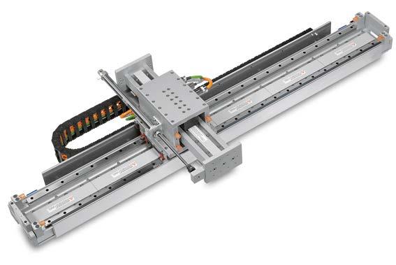
28 Positioning Systems Linear motor axes 2.8 LMX1L-S linear motor axis LMX1L linear motor axis are equipped with an iron-core motor, which provides substantial continuous force. They can also be used in cross tables. The stroke is measured via the optical or magnetic distance measuring systems incrementally or absolutely. The LMX1L-S linear motor axis have a very compact design and are available in overall lengths up to 4,000 mm. Max. acceleration 50 m/s 2 Max. speed 4 m/s Up to 4,000 mm long Hi C Bi D Table 2.12 Dimensions of power feed B Power feed vertical Power feed alignment C D Internal dimensions B i H i A C D Vertical Horizontal B Bi C Table 2.13 Technical data of LMX1L-S linear motor axis A Hi Power feed horizontal Name (article number) xxxx = stroke Motor type F c [N] F p [N] Weight of glider [kg] Length of glider v max [m/s] a max [m/s 2 ] Dimension A Dimension B LMX1L-S23-1-xxxx-D100 LMS LMX1L-S27-1-xxxx-D100 LMS LMX1L-S37-1-xxxx-D100 LMS * LMX1L-S37L-1-xxxx-D100 LMS 37L LMX1L-S47-1-xxxx-D100 LMS * LMX1L-S47L-1-xxxx-D100 LMS 47L LMX1L-S57-1-xxxx-D100 LMS * LMX1L-S57L-1-xxxx-D100 LMS 57L LMX1L-S67-1-xxxx-D100 LMS * LMX1L-S67L-1-xxxx-D100 LMS 67L LMX1L-S23-1-xxxx-D1A0 LMS /111 LMX1L-S27-1-xxxx-D1A0 LMS /111 LMX1L-S37-1-xxxx-D1A0 LMS * /116 LMX1L-S37L-1-xxxx-D1A0 LMS 37L /116 LMX1L-S47-1-xxxx-D1A0 LMS * /116 LMX1L-S47L-1-xxxx-D1A0 LMS 47L /116 LMX1L-S57-1-xxxx-D1A0 LMS * /121 LMX1L-S57L-1-xxxx-D1A0 LMS 57L /121 LMX1L-S67-1-xxxx-D1A0 LMS * /121 LMX1L-S67L-1-xxxx-D1A0 LMS 67L /121 Notes: F c = Continuous power, 100 % operating time (ED), at 120 C winding temperature F p = Peak force (1 s) Electrical parameters of LMS linear motors: see catalogue Linear Motors * Limited by back-emf of the motor winding 28
29 2.8.1 LMX1L-S linear motor axis without cover Dimensions and weight of the LMX1L-S23 linear motor axis without cover Direction = Effective Stroke () 42,5 4-Ø9H7 2,1DP;M6 1P 12DP 6-M6 1P 12DP Limit switch 92,5 2 2-Ø6H7 THRU 2 (N+1)-Ø6,5 THRU;Ø11 8,5DP (78) L1 N L-30 L All values in mm Table 2.14 Dimensions and weight of LMX1L-S23 without cover Stroke Total length L L N 1* Weight [kg] * When stroke = 100 mm the mounting hole distance increases from 150 to 300 mm 29
30 Positioning Systems Linear motor axes Dimensions and weight of the LMX1L-S27 linear motor axis without cover + Direction = Effective Stroke () ,5 Limit switch 8-M6 1P 12DP 4-Ø9H7 2,1DP; M6 1P 12DP (L3) 2 2-Ø6H7 THRU 2 (N+1)-Ø6,5 THRU; Ø 11 8,5DP (78) L1 N L-30 L All values in mm Table 2.15 Dimensions and weight of LMX1L-S27 without cover Stroke Total length L L N 1* Weight [kg] * When stroke = 100 mm the mounting hole distance increases from 150 to 300 mm 30
31 Dimensions and weight of the LMX1L-S37 and LMX1L-S37L linear motor axes without cover 11 + Direction = Effective Stroke 95 () ,5 2 2-Ø6H7 THRU 4-Ø9H7 2,1DP;M6 1P 12DP 8-M8 1,25P 16DP 2 (N+1)-Ø9THRU;Ø14 10DP Limit switch (80) 92,5 L1 N L-30 L All values in mm Table 2.16 Dimensions and weight of LMX1L-S37 and LMX1L-S37L without cover Stroke Total length L L N 1* Weight [kg] * When stroke = 100 mm the mounting hole distance increases from 150 to 300 mm 31
32 Positioning Systems Linear motor axes Dimensions and weight of the LMX1L-S47 and LMX1L-S47L linear motor axes without cover 11 + Direction = Effective Stroke ,5 () 4-Ø9H7 2,1DP;M6 1P 12DP Limit switch 92,5 2 2-Ø6H7THRU 8-M8 1,25P 16DP 2 (N+1)-Ø9THRU;Ø14 10DP (78) L1 N L-30 L All values in mm Table 2.17 Dimensions and weight of LMX1L-S47 and LMX1L-S47L without cover Stroke Total length L L N 1* Weight [kg] * When stroke = 100 mm the mounting hole distance increases from 150 to 300 mm 32
33 Dimensions and weight of the LMX1L-S57 and LMX1L-S57L linear motor axes without cover + Direction =210 Effective Stroke 100 () 92, , M8 1,25P 16DP Limit switch 2 2-Ø6H7 THRU 2 (N+1)-Ø9 THRU;Ø14 10DP (78) L1 N L-30 L All values in mm Table 2.18 Dimensions and weight of LMX1L-S57 and LMX1L-S57L without cover Stroke Total length L L N 1* Weight [kg] * When stroke = 100 mm the mounting hole distance increases from 150 to 300 mm 33
34 Positioning Systems Linear motor axes Dimensions and weight of the LMX1L-S67 and LMX1L-S67L linear motor axes without cover + Direction =210 Effective Stroke 100 () 92, , M8 1,25P 16DP Limit switch 2 2-Ø6H7THRU 2 (N+1)-Ø9THRU;Ø14 10DP (78) L1 N L-30 L All values in mm Table 2.19 Dimensions and weight of LMX1L-S67 and LMX1L-S67L without cover Stroke Total length L L N 1* Weight [kg] * When stroke = 100 mm the mounting hole distance increases from 150 to 300 mm 34
35 2.8.2 LMX1L-S linear motor axis with cover Dimensions and weight of the LMX1L-S23 linear motor axis with cover Direction = Effective Stroke H () 42,5 4-Ø9H7 2,1DP;M6 1P 12DP Limit switch 92,5 2 2-Ø6H7THRU 6-M6 1P 12DP 2 (N+1)-Ø6,5THRU;Ø11 8,5DP (78) L1 N L-30 L All values in mm Table 2.20 Dimensions and weight of LMX1L-S23 with cover Stroke Total length L L N 1* Weight [kg] H * When stroke = 100 mm the mounting hole distance increases from 150 to 300 mm 35
36 Positioning Systems Linear motor axes Dimensions and weight of the LMX1L-S27 linear motor axis with cover 11 + Direction 280 Effective Stroke =210 H ,5 () 8-M6 1P 12DP Limit switch 4-Ø9H7 2,1DP;M6 1P 12DP 92,5 2 2-Ø6H7THRU 2 (N+1)-Ø6,5THRU;Ø11 8,5DP (78) L1 N L-30 L All values in mm Table 2.21 Dimensions and weight of LMX1L-S27 with cover Stroke Total length L L N 1* Weight [kg] H * When stroke = 100 mm the mounting hole distance increases from 150 to 300 mm 36
37 Dimensions and weight of the LMX1L-S37 and LMX1L-S37L linear motor axes with cover Direction = Effective Stroke H ,5 () 2 2-Ø6H7THRU Limit switch 4-Ø9H7 2,1DP;M6 1P 12DP 8-M8 1,25P 16DP 2 (N+1)-Ø9THRU;Ø14 10DP (78) 92,5 L1 N L-30 L All values in mm Table 2. Dimensions and weight of LMX1L-S37 and LMX1L-S37L with cover Stroke Total length L L N 1* Weight [kg] H * When stroke = 100 mm the mounting hole distance increases from 150 to 300 mm 37
38 Positioning Systems Linear motor axes Dimensions and weight of the LMX1L-S47 and LMX1L-S47L linear motor axes with cover Direction = Effective Stroke H ,5 () 2 2-Ø6H7THRU 4-Ø9H7 2,1DP;M6 1P 12DP 8-M8 1,25P 16DP 2 (N+1)-Ø9THRU;Ø14 10DP Limit switch (78) 92,5 L1 N L-30 L All values in mm Table 2.23 Dimensions and weight of LMX1L-S47 and LMX1L-S47L with cover Stroke Total length L L N 1* Weight [kg] H * When stroke = 100 mm the mounting hole distance increases from 150 to 300 mm 38
39 Dimensions and weight of the LMX1L-S57 and LMX1L-S57L linear motor axes with cover + Direction =210 Effective Stroke H () 92, , M8 1,25P 16DP Limit switch 2 2-Ø6H7THRU 2 (N+1)-Ø9 THRU;Ø14 10DP (78) 150 L1 N L-30 L All values in mm Table 2.24 Dimensions and weight of LMX1L-S57 and LMX1L-S57L with cover Stroke Total length L L N 1* Weight [kg] H * When stroke = 100 mm the mounting hole distance increases from 150 to 300 mm 39
40 Positioning Systems Linear motor axes Dimensions and weight of the LMX1L-S67 and LMX1L-S67L linear motor axes with cover 11 + Direction =210 Effective Stroke H () ,5 8-M8 1,25P 16DP Limit switch 92,5 2 2-Ø6H7THRU 2 (N+1)-Ø9THRU;Ø14 10DP (78) L1 N L-30 L All values in mm Table 2.25 Dimensions and weight of LMX1L-S67 and LMX1L-S67L with cover Stroke Total length L L N 1* Weight [kg] H * When stroke = 100 mm the mounting hole distance increases from 150 to 300 mm 40

41 2.9 LMV1L linear motor axis LMV1L linear motor axis are equipped with an iron-core motor, which provides substantial continuous force. These axis are equipped with pneumatic weight compensation as a standard to ensure high dynamics in a vertical direction. The moving distance is measured incrementally or absolutely via optical or magnetic encoders depending on requirements. LMV1L linear motor axis are ideal for applications with a gripper connection, in which the gripper extends completely out of the transfer area. The moved working load is approx. 20 kg. Max. acceleration 30 m/s 2 Max. speed 1.8 m/s Table 2.26 Technical data of LMV1L linear motor axis Name (Article number) Motor type F c [N] F p [N] Weight of glider [kg] LMV1L-S A100 LMS LMV1L-S A100 LMS LMV1L-S A100 LMS LMV1L-S A100 LMS Notes: F c = Continuous power, 100 % operating time (ED), at 120 C winding temperature F p = Peak force (1 s) Electrical parameters for linear motors: see catalogue Linear Motors v max [m/s] a max [m/s 2 ] Stroke 41
42 Positioning Systems Linear motor axes Dimensions of the LMV1L linear motor axis 12-Ø11 12DP; Ø6.5THRU (50) Ø9H7 Limit switch Positioning measurement system (Encoder) 15 Encoder connector Limit switch connector Motor connector Housing M6 1P 12DP Ø5THRU 3 30=90 Ø9H7 2.1DP; M6 1P 12DP All values in mm Ø9H7 2.1DP; M6 1P 12DP Table 2.27 Total length and weight of LMV1L Article number Stroke Total length L LMV1L-S A LMV1L-S A LMV1L-S A LMV1L-S A Weight [kg] 42
43 2.10 LMH1L linear motor axis Linear guideways and linear motor rare integrated in the Al-profile of the LMH axis. This enables a very compact construction. The linear motor axes LMH1L are available in two profile sizes of 160 and 200 mm width. The T-slots that are attached to the profile allow a very flexible mounting of the LMH axis and customer specific strokes LMH1L-S1 The LMH1L-S1 portal axis equipped with linear motors is designed as a complete axis with strokes up to 30 m. Several gliders can be positioned independently of each other using the linear motor technology. The distance is measured incrementally and enables positioning accuracy up to 0.05 mm. An absolute measuring system can be built in as an option. Max. acceleration 50 m/s² Max. speed 4 m/s Up to 30 m stroke C Bi Connection dimensions for the LMH1L-S1 linear motor axis Installation notes: The axis is attached to the machine bed using T-slots. The customer mechanism is also attached using T-slots on the glider. D Hi Forcer Linear motor 130 For M8 Linear guideway C Power feed vertical 7 D Stator Girder section 90 Für For 160 M8 Table 2.28 Dimensions of power feed M6 All values in mm (14) Power feed horizontal Hi Bi C Power feed alignment C D Internal dimensions B i H i Vertical Horizontal Table 2.29 Technical data of LMH1L-S1 linear motor axis Name (article number) xxxx = stroke Motor type F c [N] F p [N] Weight of glider [kg] Length of glider v max [m/s] a max [m/s 2 ] LMH1L-S13-1-xxxx-C000 LMS LMH1L-S17-1-xxxx-C000 LMS LMH1L-S17D-1-xxxx-C000 LMS 17D Notes: F c = Continuous power, 100 % operating time (ED), at 120 C winding temperature F p = Peak force (1 s) Electrical parameters for linear motors: see catalogue Linear Motors Weight of girder [kg/m] 43

44 Positioning Systems Linear motor axes/cross tables LMH1L-S2 The LMH1L-S2 portal axis equipped with linear motors is designed as a complete axis with strokes up to 30 m. Several gliders can be positioned independently of each other using the linear motor technology. The distance is measured incrementally and enables positioning accuracy up to 0.05 mm. An absolute measuring system can be built in as an option. Max. acceleration 50 m/s² Max. speed 4 m/s Up to 30 m stroke Connection dimensions for LMH1L-S2 linear motor axis Installation notes: The axis is attached to the machine bed using T-slots. The customer mechanism is also attached using T-slots on the glider. C Bi Hi Forcer Linear motor 160 Linear guideway For M10 D Power feed vertical Stator C Girder section For M10 For M8 D All values in mm Bi C Table 2.30 Dimensions of power feed Power feed alignment C D Internal dimension B i H i Vertical Horizontal Power feed horizontal Hi Table 2.31 Technical data for LMH1L-S2 linear motor axis Name (article number) xxxx = stroke Motor type F c [N] F p [N] Weight of glider [kg] Length of glider LMH1L-S23-1-xxxx-D000 LMS LMH1L-S27-1-xxxx-D000 LMS LMH1L-S27D-1-xxxx-D000 LMS 27D Notes: F c = Continuous power, 100 % operating time (ED), at 120 C winding temperature F p = Peak force (1 s) Electrical parameters for linear motors: see catalogue Linear Motors v max [m/s] a max [m/s 2 ] Weight of girder [kg/m] 44
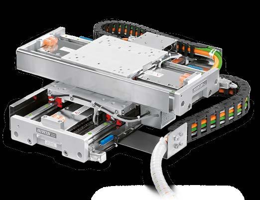
45 2.11 Cross tables The linear motor axis of the LMX series can be combined to form cross tables. The structure of the model number shows that almost any combination of LMX axis X is possible. A cross table with LMX2E axis is shown in Chapter Chapter shows a cross table with LMX2L axis LMX2E-CB5-CB8 cross table Equipped with coreless linear motors Slight inertia and fast acceleration No cogging Extremely stiff aluminium frame with low profile Simple assembly Table 2.32 Technical data for LMX2E-CB5-CB8 cross table Name (article number) xxxx = stroke Orthogonality [arc-sec] Repeatability v max [m/s] a max [m/s 2 ] Motor type Fc [N] Fp [N] Weight of glider [kg] LMX2E-CB5 CB8-xxxx-xxxx-A1 ± 10 ± Upper axis: LMC B Lower axis: LMC B Weight upper axis Notes: F c = Continuous power, 100 % operating time (ED), at 100 C winding temperature F p = Peak force (1 s) Electrical parameters for linear motors: see catalogue Linear Motors 45
46 Positioning Systems Cross tables Dimensions and weight of the LMX2E-CB5-CB8 cross table without cover Y-Axis +Direction Cable chain of Y-axis X-Axis +Direction Cable chain of X-axis Limit switch LX 4-M6 1,0P 10DP 11 LX/2 ½ Effective Stroke ½ Effective Stroke (148) 36, L2 LY/2 ½ Effective Stroke ½ Effective Stroke 160 L1 N (45,4) LY-30 LY 2 2-Ø6H7THRU 2 (N+1)-Ø6,5THRU;Ø11 8,5DP All values in mm Table 2.33 Dimensions and weight of LMX2E-CB5-CB8 without cover Stroke Total length L1 L2 N Weight of glider Weight of glider Total weight cross table Axis X Axis Y LX LY Axis X [kg] Axis Y [kg] [kg] * * When stroke = 100 mm the mounting hole distance increases from 150 to 300 mm 46
47 Dimensions and weight of the LMX2E-CB5-CB8 cross table with cover Y-Axis +Direction Cable chain of Y-axis X-Axis +Direction Cable chain of X-axis LY/2 ½ Effective Stroke ½ Effective Stroke Limit switch M6 1,0P 10DP LX ½ Effective Stroke LX/2 ½ Effective Stroke 36, (148) L2 L1 N LY-30 2 (N+1)-Ø6,5THRU,Ø11 8,5DP (45,4) LY 2 2-Ø6H7THRU All values in mm Table 2.34 Dimensions and weight of LMX2E-CB5-CB8 with cover Stroke Total length L1 L2 N Weight of glider Weight of glider Total weight cross table Axis X Axis Y LX LY Axis X [kg] Axis Y [kg] [kg] * * When stroke = 100 mm the mounting hole distance increases from 150 to 300 mm 47

48 Positioning Systems Cross tables LMX2L-S23-S27 cross table Equipped with iron-core linear motors Higher force and fast acceleration Extremely stiff aluminium frame with low profile Simple assembly Table 2.35 Technical data of LMX2L-S23-S27 cross table Name (article number) xxxx = stroke Orthogonality [arc-sec] Repeatability v max [m/s] a max [m/s 2 ] Motor type Fc [N] Fp [N] Weight of glider [kg] LMX2L-S23 S27-xxxx-xxxx-A1 ± 10 ± Upper axis: LMS ,5 Lower axis: LMS Weight upper axis + 9,5 Notes: Fc = Continuous power, 100 % operating time (ED), at 120 C winding temperature Fp = Peak force (1 s) Electrical parameters for linear motors: see catalogue Linear Motors 48
49 Dimensions and weight of the LMX2L-S23-S27 cross table without cover Y-Axis +Direction Cable chain of Y-axis X-Axis +Direction Cable chain of X-axis Limit switch 6-M6 1,0P 12DP LX LX/2 ½ Effective Stroke ½ Effective Stroke ,5 (148) L LY/2 ½ Effective Stroke ½ Effective Stroke Ø6H7THRU L1 N LY-30 (30,4) LY 2 (N+1)-Ø6,5THRU,Ø11 8,5DP All values in mm Table 2.36 Dimensions and weight of LMX2L-S23-S27 without cover Stroke Total length L1 L2 N Weight of glider Weight of glider Total weight cross table Axis X Axis Y LX LY Axis X [kg] Axis Y [kg] [kg] * * When stroke = 100 mm the mounting hole distance increases from 150 to 300 mm 49
50 Positioning Systems Cross tables/gantry systems Dimensions and weight of the LMX2L-S23-S27 cross table with cover Y-Axis +Direction Cable chain of Y-axis X-Axis +Direction Cable chain of X-axis Limit switch 6-M6 1,0P 12DP LX LX/2 ½ Effective Stroke ½ Effective Stroke ,5 (148) L LY/2 ½ Effective Stroke ½ Effective Stroke Ø6H7THRU L1 N LY-30 (30,4) LY 2 (N+1)-Ø6,5THRU,Ø11 8,5DP All values in mm Table 2.37 Dimensions and weight of LMX2L-S23-S27 with cover Stroke Total length L1 L2 N Weight of glider Weight of glider Total weight cross table Axis X Axis Y LX LY Axis X [kg] Axis Y [kg] [kg] * * When stroke = 100 mm the mounting hole distance increases from 150 to 300 mm 50

51 2.12 Gantry systems The standardized gantry systems of the LMG2A series are systems with one-sided step bearings. The LMG2A-C type has coreless linear motors. The LMG1A-S type is driven by iron-core linear motors LMG2A-CB6 CC8 gantry system Equipped with coreless linear motors Slight inertia and fast acceleration No cogging Stiff aluminium bridge Simple assembly Table 2.38 Technical data of LMG2A-CB6 CC8 gantry system Name (article number) xxxx = stroke Orthogonality [arc-sec] Repeatability v max [m/s] a max [m/s 2 ] Motor type Fc [N] Fp [N] Weight of glider [kg] LMG2A-CB6 CC8-xxxx-xxxx-A1 ± 10 ± / Upper axis: LMC B ,0 Lower axis: LMC C Weight upper axis + 3,5 Notes: Fc = Continuous power, 100 % operating time (ED), at 100 C winding temperature Fp = Peak force (1 s) Electrical parameters for linear motors: see catalogue Linear Motors 51
52 Positioning Systems Gantry systems Dimensions and weight of the LMG2A-CB6 CC8 gantry system Limit switch X-Axis + Direction ½ Effective stroke ½ Effective stroke 59,5 280 Y-Axis + Direction Limit switch ½ Effective stroke = ½ Effective stroke 6-M6 1P 12DP , ,5 2-Ø6H7 10DP W3 2 W3 140 L1 150 W1 150 W 77 (W2) 3 (N+1)-M6 1P 12DP 2 (N+1)-Ø11 THRU;Ø18 12DP 200 N 200 (L1) L Table 2.39 Dimensions and weight of LMG2A-CB6 CC8 All values in mm Axis X (top) Stroke W W1 W2 W3 Weight of glider [kg] Axis Y (below) Stroke N L L1 Weight of glider [kg] Total weight Axis X Total weight Axis X Total weight Axis X Total weight Axis X Total weight Axis X + 6 Total weight Axis X [kg] 52
53 LMG2A-S13 S27 gantry system Equipped with iron-core linear motors Higher force and fast acceleration Less cogging and constant speed Stiff aluminium bridge Simple assembly Table 2.40 Technical data of LMG2A-S13 S27 gantry system Name (article number) xxxx = stroke Orthogonality [arc-sec] Repeatability v max [m/s] a max [m/s 2 ] Motor type Fc [N] Fp [N] Weight of glider [kg] LMG2A-S13 S27-xxxx-xxxx-A1 ± 10 ± / Upper axis: LMS Lower axis: LMS Weight upper axis + 7 Notes: Fc = Continuous power, 100 % operating time (ED), at 120 C winding temperature Fp = Peak force (1 s) Electrical parameters for linear motors: see catalogue Linear Motors 53
54 Positioning Systems Gantry systems Dimensions and weight of the LMG2A-S13 S27 gantry system X-Axis + Direction 280 ½ Effective stroke Y-Axis + Direction ½ Effective stroke ½ Effective stroke 43, = ½ Effective stroke 6-M6 1P 12DP Limit switch , ,5 2-Ø6H7 10DP W3 2 W W1 150 W 102 L1 (W2) 3 (N+1)-M6 1P 12DP 2 (N+1)-Ø11THRU;Ø18 12DP 200 N 200 (L1) L Table 2.41 Dimensions and weight of LMG2A-S13 S27 All values in mm Axis X (top) Stroke W W1 W2 W3 Weight of glider [kg] Axis Y (below) Stroke N L L1 Weight of glider [kg] Total weight Axis X Total weight Axis X Total weight Axis X Total weight Axis X Total weight Axis X + 8 Total weight Axis X [kg] 54


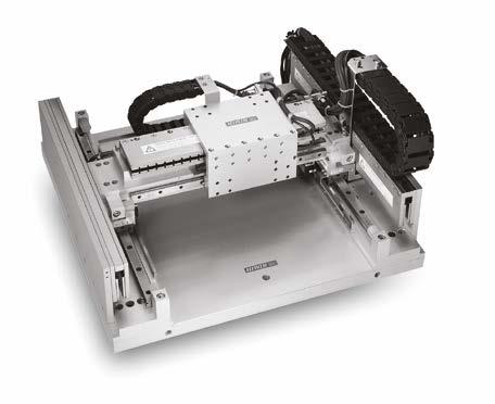
55 3. Customized positioning systems The standardized positioning stages shown in this catalogue are designed to handle many different kinds of positioning tasks. For positioning tasks that cannot be solved using standard stages, application engineers are available to work out an optimized solution. A few customized solutions are shown on the next four pages. Sometimes only the mechanics are customized. In the planar motor example, the customized solution used special software for optimum integration of the positioning system in the production process. 3.1 Examples Economic installation and inspection XY gantry systems make many applications extremely economical. Setup of the gantry from standard components. Standard axis of the LMX1L series Repeatability ± 2 µm Supplied with machine bed Micro shapes and macro shapes Milling and microstructures with cutting tools and lasers are application areas in which gantry systems can deliver a number of benefits. They are also an excellent buy for your money. Coreless LMC motors Repeatability ± 2 µm Tried and tested technology with high output Planar motors Servo-planar motors offer an excellent technological platform for inspection tasks. In inspection of printed circuit boards, they have an optical sensor for complete monitoring of printed conductive tracks and SMD components. Air-cushion bearing ensures minimum wear Guaranteed levelness for the complete stroke (up to 1000 mm 1000 mm) Repeatability ± 3 µm 55


56 Positioning Systems Customized positioning systems Wafer quality control at the highest level High precision X-Y Stages with air-cushions are the prerequisites for surface monitoring, which even find the smallest errors, for example, in wafer production for the electronics and chip industries. Flatness ± 2 µm Repeatability ± 2 µm Accuracy ± 5 µm Resolution 5 nm Microsystem technology and wafer processing Absolute precision and suitability for clean room conditions are the prerequisites for every drive in microsystem technology and wafer processing. Linear motor X-Y Stages are ideal for these tasks. Stroke 200 mm 200 mm, optional 300 mm 300 mm Flatness ± 4 µm across the complete stroke Repeatability ± 1 µm across both axes Accuracy ± 4 µm across both axes Clean room suitability class 100, optional class 10 Optionally suitable for vacuums up to 10-3 mbar Overview for laser scanners High degree of synchronization and extended operating lives are a must for optical inspection systems such as laser scanners. Linear motors with air bearings fulfil these requirements. No friction thanks to air bearings No cogging thanks to coreless linear motors Stroke up to 1,500 mm Photovoltaic-panel assembly High dynamic positioning of silicium cells for 24 hours each day. Linear motors also in vertical axes enable a long durability Vertical axes with adjustable mass compensation and clamping element for emergency-stop. 56


57 X-ray-inspection of printed circuit boards Delivery of the whole linear-motor-system consisting of Linear motor axis, drives, cables for an inline inspection machine. System with coreless LMC components High dynamism in spite of 100 kg mass to move Stroke: mm Repeatability: ± 1µm Automatic assembly Dynamic Assembly of circuit boards in fully automated assembly lines. Gantry system with LMS components and KK-stage (axis Z) Stroke: mm Acceleration: 20 m/s² Flatness: ± 20 µm Rectangularity: 0.01 Interferometrical survey of the axis Delivery ready assembled in the base frame Moveable Saw Linear motor axis enables the cutting during the transport of bars. Customised LM-system with LMS47D Cycle time approx. 1.3 s (mass: 55 kg, Stroke: 1.5 m) Speed: 3 m/s Acceleration: m/s² Film transport Compact and flat linear motor axis with high power density integrated in the production line. Two parallel LMC-axes Stroke: 300 mm All components assembled on a customised base frame mm 57


58 Positioning Systems Planar servo motors and planar motors Laser trimming Optimal results make a high demand on evenness and rectangularity on a large stroke. The metal particles of the laser machining necessitate the bellow cover. Cross table with bellow cover Stroke: mm Repeatability: ± 2 µm Flatness: ± 0.01 / 300 mm Rectangularity: ± 5 arcsec Dispenser Highest requirements on the flatness. Stroke of cross table: mm High rigidity of the lower axis due to the steel frame Upper axis stiffened by aluminium profile Creation of a calibration chart to compensate the deviation of the flatness Flatness: ± 10 µm / 300 mm Repeatability: 5 µm Laser scripting High accuracy due the use of glass scales. Customised LMC linear motor system Lower axis positions the workpiece. Upper axis operates the laser Stroke: mm Repeatability: ± 1µm Rectangularity: 8 µm Flatness: ± 5 µm Laser exposure Excellent results enabled due to the very smooth motion of the coreless linear motor axis. 4 forcers on each axis High degree of synchronization due to the use of special linear guideways Optimised adaptation of the axis profile to the existing machine frame 58
.")
59 4. Planar servo motors and planar motors XY movements with air suspension through a planar servo stepping motor with integrated stroke measurement. Can be operated above head and even in a vacuum. 4.1 LMSP planar servo motor LMSP planar servo motors are equipped with integrated stroke measurement sensors and work with position control (closed loop). XY table Closed loop thanks to integrated positioning measurement Stepping motor facilitates the use of simple drive electronics Air suspension free of wear No externally measurable magnetic fields Practically no heating up Can be built in above head Stator area up to mm Can be used in vacuums Configuration of LMSP with LMDX servo driver LMSP forcer Stator LMSP LMDX drive amplifier (see Page 62) Connection block Air connection 3 4 bar If required, 24 V supply voltage for the I/O of the control card PCI4P control card built into PC 59
60 Positioning systems Planar servo motors and planar motors Technical data of the LMSP planar servo motor Connection dimensions of the LMSP planar servo motor (For values W f see Table 4.1, for values W s see Table 4.2) LMSP Stator (W s + 53) W s B s 6-M10 1.5P/10DP Air connection Ø 1/4 (Ø 6 mm) (86 + Hs) Hs Hf Power feed LMSPX1 Forcer W f B f (Ls + 16) Ls As As 72 Af Lf D-SUB 15-pin D-SUB 25-pin B f W f B f LMSPX2 Forcer Af Af Lf 6-M5 0.8P/10DP Table 4.1 Technical data of LMSP All values in mm Forcer Performance Symbol Unit LMSPX1 LMSPX2 Maximum feed force T m N 140 Resolution R s mm Repeatability R p mm Accuracy A c mm ± ± Maximum speed V m/s 0.9 0,8 Maximum load kg Length L f mm Width W f mm Height H f mm Air pressure P a kg/cm Air flow rate F a l/min Weight M f kg Mounting hole distance A f B f mm mm
61 Table 4.2 Dimensions and weight of stators LMSP-P1 to LMSP-P6 Unit P1 P2 P3 P4 P5 P6 Stator dimensions L S W S mm Max. stroke LMSPX1 mm (one forcer) LMSPX2 mm Stator height mm Stator weight kg Mounting hole distance A S B S mm ( ) Number of mounting holes n Article numbers for LMSP planar servo motors LMSP X1 1 P3 Planar servo motor Stator type (see Table 4.2) P1, P2, P3, P4, P5, P6 Forcer type (see Table 4.2) X1, X2 Number of forcers 61

62 Positioning systems Planar servo motors and planar motors LMDX servo driver The servo driver for the LMSP planar servo motor is available in two different voltage versions and with a digital I/O interface card. Dimensions of the LMDX servo driver 432 All values in mm Ø116 PCDØ (5) Table 4.3 Technical data of LMDX Unit Power supply Voltage V AC (article number LMDX1) (article number LMDX2) Frequency H z 50/60 Power V A 500 (max.) Output current A 3 (max.) Interface Parameterisation: RS baud, 8 data bits, 2 stop bits, unequal parity Digital I/O signal DXIO modular card: 8 inputs: including HOME and RESET 6 outputs: including IN-POSITION, ALARM, SVON DXIO16 modular card (optional): 16 inputs, 16 outputs Pulse Pulse STEP/DIRECTION Resolution µm/pulse up to min. 1 (configurable) Weight kg 13.3 Max. operating temperature C 50 Value 62
63
 7 81 9 32 78-0 Fax +49 (0) 7 81 9 32 78-90 info@hiwin.de www.hiwin.de Taiwan Headquarters HIWIN Technologies Corp. No.")

 Phone +39 0 2 93 90 09 41 Fax +39 0 2 93 46 93 24 info@hiwin.it www.hiwin.it Poland HIWIN GmbH ul.")
 55 5 00 25 Fax +41 (0) 55 5 00 20 info@hiwin.")

64 Linear Guideways Ballscrews Linear Motor Systems Linear Axes with Ballscrews Linear Actuators Ball Bearings Linear Motor Components Rotary Tables Drives Germany HIWIN GmbH Brücklesbünd 2 D Offenburg Phone +49 (0) Fax +49 (0) info@hiwin.de Taiwan Headquarters HIWIN Technologies Corp. No. 7, Jingke Road Nantun District Taichung Precision Machinery Park Taichung 40852, Taiwan Phone Fax business@hiwin.com.tw Taiwan Headquarters HIWIN Mikrosystem Corp. No. 6, Jingke Central Road Nantun District Taichung Precision Machinery Park Taichung 40852, Taiwan Phone Fax business@hiwinmikro.tw Italy HIWIN Srl Via De Gasperi, 85 I Rho (MI) Phone Fax info@hiwin.it Poland HIWIN GmbH ul. Puławska 405a PL Warszawa Phone +48 (0) Fax +48 (0) info@hiwin.pl Czechia HIWIN s.r.o. Medkova 888/11 CZ BRNO Phone Fax info@hiwin.cz Slovakia HIWIN s.r.o., o.z.z.o. Mládežnicka 2101 SK Považská Bystrica Phone Fax info@hiwin.sk Switzerland HIWIN Schweiz GmbH Eichwiesstrasse 20 CH-8645 Jona Phone +41 (0) Fax +41 (0) info@hiwin.ch France HIWIN France s.a.r.l. 20 Rue du Vieux Bourg F Echauffour Phone +33 (2) Fax +33 (2) info@hiwin.fr Austria HIWIN GmbH info@hiwin.at Hungary HIWIN GmbH info@hiwin.hu Netherlands HIWIN GmbH info@hiwin.nl Japan HIWIN Corp. mail@hiwin.co.jp USA HIWIN Corp. info@hiwin.com China HIWIN Corp. Korea HIWIN Corp. Singapore HIWIN Corp. PS-06-2-EN-1412-K
Positioning Systems Linear Motor Systems
 www.hiwin.de Positioning Systems HIWIN GmbH Brücklesbünd 2 D-77654 Offenburg Phone +49 (0) 7 81 9 32 78-0 Fax +49 (0) 7 81 9 32 78-90 info@hiwin.de www.hiwin.de All rights reserved. Complete or partial
Positioning Systems Linear Motor Systems
 www.hiwin.de Positioning Systems Linear Motor Systems HIWIN GmbH Brücklesbünd 2 D-77654 Offenburg Phone +49 (0) 7 81 9 32 78-0 Fax +49 (0) 7 81 9 32 78-90 info@hiwin.de www.hiwin.de All rights reserved.
Positioning Systems.
 Positioning Systems www.hiwin.de HIWIN GmbH Brücklesbünd 2 D-77654 Offenburg Telephone +49 (0) 781 9 32 78-0 Telefax +49 (0) 781 9 32 78-90 info@hiwin.de www.hiwin.de All rights reserved. Reprinting of
Positioning Systems. Linear Motor Stages Product Overview. LMX1E-C Page 14. LMX1L-S Page 19.
 8 inear Motor Stages 2.1 Product Overview MX1E-C Page 14 Complete linear stage with coreless motor, type MC Excellent for applications with a high degree of synchronous operation requirements Also for
Linear Motor System. Technical Information.
 Linear Motor System Technical Information www.hiwinmikro.com.tw Customized Positioning Systems page 1 Linear Motor Stages page 7 Planar Motor page 35 Linear Motor Components page 41 Torque Motor Rotary
Linear Motor System. Technical Information.
 inear Motor System Technical Information www.hiwinmikro.com.tw igh speed igh precision Multifunctional integration Ecology first umanistic technology TAIWA EXCEECE GOD AWARD 20, 2009, 2008 TAIWA EXCEECE
Phone: Fax:
 www. hi wi n. c om HI WI NCor por at i on 1400Madel i nelane El gi n,i L60124 Phone:8478272270 Fax:8478272291 i nf o@hi wi n. c om www. hi wi n. c om Welcome to HIWIN Welcome to HIWIN Directly driven HIWIN
Innovation & Excellence. Index. Index. Innovation & Excellence. Introduction. Our Solutions 4-5. MLE / MLZ Series iron core motor
 Index Innovation & Excellence Introduction 3 Our Solutions 4-5 MLE / MLZ Series iron core motor 6-7 MLE 2 Linear Units 8-9 MLE 3 Linear Units 10-11 Index MLE 5 Linear Units MLE 7 Linear Units MLZ 2 Linear
Replace your belt, ball screw or rack and pinion mechanism with a simple and economical linear servo motor actuator
 LINEAR SERVO ECONO-SLIDE Ultimate Solution for High Throughput Precision Positioning Replace your belt, ball screw or rack and pinion mechanism with a simple and economical linear servo motor actuator
Precision Modules PSK
 Precision Modules PSK The Drive & Control Company Rexroth Linear Motion Technology Ball Rail Systems Roller Rail Systems Standard Ball Rail Systems Super Ball Rail Systems Ball Rail Systems with Aluminum
Mini-MAG Positioning Products
 Mini-MAG Positioning Products Miniature Linear Stage The Mini-MAG (MMX) line of miniature linear stages blends the ultimate in performance, reliability, and value, delivering nearly twice the accuracy
Compact Modules. with ball screw drive and toothed belt drive R310EN 2602 ( ) The Drive & Control Company
 The Drive & Control Company") with ball screw drive and toothed belt drive R310EN 2602 (2007.02) The Drive & Control Company Bosch Rexroth AG Linear Motion and Assembly Technologies Ball Rail Systems Roller Rail Systems Linear Bushings
with ball screw drive and toothed belt drive R310EN 2602 (2007.02) The Drive & Control Company Bosch Rexroth AG Linear Motion and Assembly Technologies Ball Rail Systems Roller Rail Systems Linear Bushings
EMC-HD. C 01_2 Subheadline_15pt/7.2mm
 C Electromechanical 01_1 Headline_36pt/14.4mm Cylinder EMC-HD C 01_2 Subheadline_15pt/7.2mm 2 Elektromechanischer Zylinder EMC-HD Short product name Example: EMC 085 HD 1 System = ElectroMechanical Cylinder
Linear Axes Technical Data Summary
 components Technical Data Summary Pneumatic Axes Electrical Axes LM 6 P LM 8 P LM 8 PV LM 10 P LM 6 PE LM 8 PE LM 8 PEV LM 10 PE Standard stroke lengths [mm]: h 0-150 Overall length [mm]: L 408 468 468
STAR Ball Rail Tables TKK
 before operating X4 X8 X3 X1 X2 S1 S2 12 4 13 5 14 6 15 7 16 8 1 2 3 9 10 11 1 2 3 4 5 6 8.8 S3 X30 Indramat DANGER! AC-CONTROLLER High voltage Danger of electrical shock Do not touch electrical connnections
CKR Compact Modules with Ball Rail Guides and Toothed Belt Drive. The Drive and Control Company
 CKR Compact Modules with Ball Rail Guides and Toothed Belt Drive The Drive and Control Company Bosch Rexroth Corp. Linear Motion and Assembly Technologies CKR RE 8 615 (03.006) Rexroth Linear Motion Technology
Javelin Series Motors
 IRONLESS Applimotion Motors & Actuators PRODUCT DATA SHEET Javelin Series Motors Low-Profile Linear Motors for the World s Machines and Robots The Javelin Series enables OEMs to design high performance,
Positioning Systems. Torque Motor Rotary Tables Product Overview and Application Areas
 62 M99TE5-15 5.1 Product Overview and Application Areas The extremely rigid connection between motor and load, and a servo-drive regulation ensures excellent acceleration capabilities and good uniformity
VRG Series. Versatile Robust H and T Drive Gantry. core motors (ACM series) or ironless motors (AUM series)
 or ironless motors (AUM series)") VRG Series Versatile Robust H and Drive Gantry Direct drive, zero backlash linear motor Versatile gantry with drive or H drive configuration, with options of various iron core motors (ACM series) or ironless
VRG Series Versatile Robust H and Drive Gantry Direct drive, zero backlash linear motor Versatile gantry with drive or H drive configuration, with options of various iron core motors (ACM series) or ironless
Precision Modules PSK
 Precision Modules PSK 2 Bosch Rexroth AG Precision Modules PSK R999000500 (2015-12) Identification system for short product names Short product name Example:: P S K - 050 - N N - 1 System = Precision Module
Extruded Positioning Stage
 Extruded Positioning Stage Single-axis stage Turnkey operation Modular aluminum construction with integral brushless linear motor, linear encoder, limit switches, cable carrier, linear bearings and bellows
Contents. Page. 1. Product description. 2. The AXC line of linear axes. 3. AXLT line of linear tables. AXC and AXS product overview...
 SNR Industry Contents Page 3 1. Product description AXC and AXS product overview... 6-8 Dynamic load ratings of the linear motion systems... 9 Compact modules... 10-11 Linear tables... 12 Telescopic axes...
Ball Rail Systems RE / The Drive & Control Company
 Ball Rail Systems RE 82 202/2002-12 The Drive & Control Company Rexroth Linear Motion Technology Ball Rail Systems Roller Rail Systems Standard Ball Rail Systems Super Ball Rail Systems Ball Rail Systems
Actuator Units NEW All-in-one-solution
 Actuator Units NEW All-in-one-solution Axis Servo Motor Amplifier Actuator Units Economy Series ES4 p. 06-07 ES6 p. 08-09 EC3 p. 10-11 EC4 p. 12-13 LM Guide Actuator KR26 p. 16-17 KR33 p. 18-19 Linear
Linear Motors & Servo Drives 3x400VAC. Linear Motor Series P The linear motor technology for industrial applications. Peak force up to 2 500N
 Linear Motors & Servo Drives 3x400VAC Linear Motor Series P10- Peak force up to 2 500N Velocity up to 5m/s Acceleration up to 100g Free positioning Long life: Linear direct drive The linear motor technology
Positioning Systems Linear Axes with Ballscrew Accessories
 www.hiwin.de Positioning Systems Linear xes with allscrew ccessories HIWIN GmbH rücklesbünd 2 D-77654 Offenburg Telephone +49 (0) 7 8 9 78-0 Fax +49 (0) 7 8 9 78-90 info@hiwin.de www.hiwin.de ll rights
Mini-MAG (MMG) Positioning Products Ultra Compact Linear Motor Stages
 Positioning Products Ultra Compact Linear Motor Stages") Mini-MAG (MMG) Positioning Products Ultra Compact Linear Motor Stages The Mini-MAG (MMG) line of positioning stages blends the ultimate in performance, reliability, and value, delivering nearly twice the
Mini-MAG (MMG) Positioning Products Ultra Compact Linear Motor Stages The Mini-MAG (MMG) line of positioning stages blends the ultimate in performance, reliability, and value, delivering nearly twice the
ROTARY TABLES SERIE TC TECHNOLOGY THAT INSPIRES
 ROTARY TABLES SERIE TC TECHNOLOGY THAT INSPIRES TC FIXED-STATION ROTARY INDEXING TABLES TC ROTARY INDEXING TABLE TC ROTARY INDEXING TABLE: RELIABILITY FOR A LIFETIME EXTENDED WARRANTY Using our rotary
Portal modules.
 Portal modules www.comoso.com www.comoso.com Portal modules PORTAL MODULES Series Size Page Portal modules PMP 114 PMP 16 118 PMP 25 124 EPM 130 EPM 37 138 EPM 48 146 The SCHUNK program offers linear technology
USER-PROGRAMMABLE AND ROBUST
 NC FREELY PROGRAMMABLE ROTARY TABLES NC ROTARY TABLE NC ROTARY TABLE: USER-PROGRAMMABLE AND ROBUST OPTIMISED BEARINGS To achieve maximum quality and reliability, even when under load, all roller bearings
PRO165LM Series. Mechanical Bearing, Linear Motor Stage. Improved second-generation design. Rugged mechanical construction
 Linear Stages Mechanical Bearing, Linear Motor Stage Improved second-generation design Rugged mechanical construction Direct-drive linear motor for ultra-precise motion Ten models with travels from 100
Product overview. 10 Bosch Rexroth Corporation Compact Modules R310A 2602 ( ) Compact Modules CKK. Compact Modules with ball screw drive (CKK)
 Compact Modules CKK. Compact Modules with ball screw drive (CKK)") 10 Bosch Rexroth Corporation R310A 2602 (2008.09) CKK with ball screw drive (CKK) Product overview are precision, ready-to-install linear motion systems characterized by their high performance and compact
10 Bosch Rexroth Corporation R310A 2602 (2008.09) CKK with ball screw drive (CKK) Product overview are precision, ready-to-install linear motion systems characterized by their high performance and compact
ST AND SW TORQUE ROTARY UNITS
 ST/SW ROTATING UNITS ST/SW TORQUE ROTARY UNIT ST AND SW TORQUE ROTARY UNITS CABLE CONNECTION Compact connector for any orientation of cable connection WEISS APPLICATION SOFTWARE Fast, easy and secure setting
Product Description. Characteristic features R310A 2402 ( ) Linear Modules MLR
 Linear Modules MLR") 9 Bosch Rexroth Corporation R310A 40 (1.11) MLR Product Description Characteristic features MLR...: with Cam Roller Guide and Toothed Belt Drive for high-speed applications (up to 10 m/s) with Cam Roller
9 Bosch Rexroth Corporation R310A 40 (1.11) MLR Product Description Characteristic features MLR...: with Cam Roller Guide and Toothed Belt Drive for high-speed applications (up to 10 m/s) with Cam Roller
Positioning Systems Linear Axes with Ballscrew Accessories
 www.hiwin.de Positioning Systems Linear xes with allscrew ccessories HIWIN GmbH rücklesbünd 2 77654 Offenburg Germany Tel. +49 (0) 7 8 9 78-0 Fax +49 (0) 7 8 9 78-90 info@hiwin.de www.hiwin.de ll rights
PIglide RM Rotation Stage with Air Bearings
 PIglide RM Rotation Stage with Air Bearings Friction-Free, Ideal for Indexing, Positioning, Scanning, Measuring Technology A-62x Cleanroom compatible Motion platform diameter from 50 mm to 300 mm Load
PRO225LM Series. Mechanical Bearing, Linear Motor Stage. Improved second-generation design. Rugged mechanical construction
 Linear Stages Mechanical Bearing, Linear Motor Stage Improved second-generation design Rugged mechanical construction Direct-drive linear motor for ultra-precise motion Twelve models with travels from
Берг АБ Тел. (495) , факс (495)
 , факс (495)") AUTOMATION Linear- and Rotary Modules Table of Contents 1 Product Overview............................................. 4 1.1 Selection of the Linear Modules................................. 8 1.2 Selection
AUTOMATION Linear- and Rotary Modules Table of Contents 1 Product Overview............................................. 4 1.1 Selection of the Linear Modules................................. 8 1.2 Selection
Standard Street, El Segundo CA BRUSHLESS SERVO MOTORS
 BRUSHLESS SERVO MOTORS To accommodate your complete servo system requirements, Glentek manufactures four complete series (GMB, GMBF, GMBM and GMBN) of high performance, permanent magnet brushless servo
The Advantages of Linear Direct Drives
 Linear Direct Drives High throughput, high precision, and maintenance-free: Linear direct drives from Kollmorgen set the standard for performance and effectiveness. These are brushless 3-phase servo motors
Ultra Series: Crossed Roller Ultra Precision Stages
 Ultra Series: Crossed Roller Ultra Precision Stages Bayside Motion Group, has developed Ultra Positioning Stages for applications requiring the ultimate in accuracy. Available with a linear motor, ball
PRO280LM Series. Mechanical Bearing, Linear Motor Stage. Improved second-generation design. Rugged mechanical construction
 Linear Stages Mechanical Bearing, Linear Motor Stage Improved second-generation design Rugged mechanical construction Direct-drive linear motor for ultra-precise motion Eight models with travels from 300
Motion without compromise
 Toothed belt and spindle axes ELGA Clean, protected, strong Motion without compromise Highlights Protected: insensitive to harsh ambient conditions Clean: virtually no particle emissions for use in cleanrooms
Siemens AG SIMOTICS T-1FW3 Torque Motors. The Powerful Torque Motors. Edition February Brochure. siemens.
 SIMOTICS T-1FW3 Torque Motors The Powerful Torque Motors Brochure Edition February 2017 siemens.com/torquemotors The powerful torque motors Overview The right torque at the right moment this is decisive
PKS-PRO - E A - J P 2 2
 PKS-PRO-E-10 - Servo System FEATURES Input Voltage Range of 170-253 VAC of 450 oz-in 1.0 kwatt Power Rating 2,500 PPR Incremental Encoder Fully Enclosed and Self-Cooled Oil Seal and Optional Brake High
AC-synchronous motors. Series LSM-36. Catalogues
 Direct Drive Systems AC-synchronous motors Series LSM-36. Catalogues Motor Magnet way Minsk 2008 Rev. Nov. 2008 Ruchservomotor Ltd. BY-220019, Montazhnikov 5, Minsk, Republic of Belarus tel. +375(17)254-04-43
Any reproduction, even partial, is allowed only by written permission by Rollco.
 LINEAR UNIT E-SMART Every care has been taken to ensure the accuracy of the information contained in this catalogue, but no liability can be accepted for any errors or omissions. We reserve the right to
A5 BELT-DRIVEN RODLESS ELECTRIC AXIS, SERIES ELEKTRO BK
 BELT-DRIVEN RODLESS ELECTRIC AXIS, SERIES ELEKTRO BK Belt-driven rodless electric axis with a V-Lock interface. The structure features an extremely lightweight yet high-strength anodised aluminium extruded
SGL Series. Single Guide Linear Motor Stage. Zero cogging and backlash ironless linear motor actuator. High speed and high acceleration
 SGL Series Single Guide Linear Motor Stage Direct drive Zero cogging and backlash ironless linear motor actuator High speed and high acceleration Fast response and quick settling time Smooth motion at
Catalogue. Portal Axes PAS
 Catalogue Portal xes PS Portal xes PS Table of Content Product Description............................... 2 Ballscrew axes.................................... Product description.............................
premo servo actuators
 servo actuators 20 21 the powerful servo actuator platform Absolute precision meets perfect motion: combines precision with motion more efficiently than ever. The central idea behind the first fully scalable
HBI 22. Integrated Three-phase Synchronous Drive
 HBI 22 Integrated Three-phase Synchronous Drive positioning capability up to 9 Watts rated output power with linear hall sensor system with or without parking brake Motor type Dimension L1 L2 HBI 223 125
PRO115LM Series. Mechanical Bearing, Linear Motor Stage. Aerotech s smallest sealed linear motor stage. Rugged mechanical construction
 Linear Stages Mechanical Bearing, Linear Motor Stage Aerotech s smallest sealed linear motor stage Rugged mechanical construction High-performance in a cost-effective package Direct-drive linear motor
V SWISS MADE LINEAR TECHNOLOGY
 Compact units Excerpt from main catalogue SWISS MADE LINEAR TECHNOLOGY V 11-15 Line Tech compact units Table of contents Product overview 106 107 Design fundamentals / Lubrication / Maintenance 108 Profile
ELECTRIC ACTUATOR - RODLESS ELEKTRO SK SERIES ACTUATORS
 ELECTRIC ACTUATOR - RODLESS ELEKTRO SK SERIES 1 ELECTRIC AXIS - RODLESS ELEKTRO SK SERIES Electric axis without screw piston rod, with V-Lock interface. The cylinder frame is made of anodized extruded
Compact Modules CKK/CKR 9-70
 Compact Modules CKK/CKR 9-70 (with Ball Rail System, Ball Screw Drive or Toothed Belt Drive) R310EN 2624 (2008.10) The Drive & Control Company Bosch Rexroth AG Linear Motion and Assembly Technologies Ball
Symbol Unit LMCA2 LMCA3 LMCA4 LMCA5 LMCA6 LMCB2 LMCB3 LMCB4 LMCB5 LMCB6 LMCB7 LMCB8 LMCBA LMCC7 LMCC8
 58 M99TE6-122 Positioning Systems Linear Motor Components 4.3 Linear Motors, LMC Series 4.3.1 Linear Motors, LMCA, LMCB, LMCC Series HIWIN synchronous linear motors LMC are the born sprinters. They are
Omni Series Motors. Applimotion Motors & Actuators TORQUE. Low-Profile Direct Drive Motors for the World s Machines and Robots PRODUCT DATA SHEET
 TORQUE Motors & Actuators PRODUCT DATA SHEET Omni Series Motors Low-Profile Direct Drive Motors for the World s Machines and Robots The Omni Series enables OEMs to design high performance, reliable, small
ATS100 Series. Mechanical Bearing, Ball-Screw Stage. Long life linear motion guide bearing system. Ultra-fine resolution. Integral bellows waycovers
 ATS100 Series Mechanical Bearing, Ball-Screw Stage Long life linear motion guide bearing system Ultra-fine resolution Integral bellows waycovers Low profile, compact design Linear Stages ATS100 Series
ServoTube. Linear Motors Linear Actuators Modules Gantries. A Division of Analogic Corporation
 ServoTube Linear Motors Linear Actuators Modules Gantries A Division of Analogic Corporation Tubular Motor Technology Motor Technology Comprising just two parts, a rod and forcer, the tubular linear motor
The Latest Sensor Trends
 Sensing & Feedback Technologies The Latest Sensor Trends Agenda Miniature sensors open up new applications Alternatives to Fiber optics Pneumatic cylinder sensing: Dual systems, analog and lifetime warranties
ALS20000 Series. Mechanical Bearing, Linear Motor Stage. Protective metal waycover. Integral cable management system
 ALS20000 Series Mechanical Bearing, Linear Motor Stage Protective metal waycover Integral cable management system Ideally suited for clean-room applications Compact, high-performance, linear motor stage
1. Product overview Basic-Line-Module AXN Product description Basic-Line-Module AXN 4-5. Guide system Roller guide 6 Drive system Gear belt 7
 Directory Page 1. Product overview Basic-Line-Module AXN 3 2. Product description Basic-Line-Module AXN 4-5 Guide system Roller guide 6 Drive system Gear belt 7 3. Basic-Line-Modul AXN 45-Z 8-9 AXN 65-Z
ECO225LM Series. Mechanical Bearing, Linear-Motor Stage. High-performance in a cost-effective, economic package. Rugged mechanical design
 Linear Stages Mechanical Bearing, Linear-Motor Stage High-performance in a cost-effective, economic package Rugged mechanical design Direct-drive linear motor for precision motion Nine models with travels
Screw Driven automation tables
 automation tables Precise multi-axis positioning systems play an integral part in today s semiconductor, computer peripheral, solar power, flat panel, life sciences, lab automation, biomedical and electronics
Precision Modules PSK. The Drive & Control Company
 Precision Modules PSK The Drive & Control Company 2 Bosch Rexroth Coporation Precision Modules PSK R310A 2414 (2008.07) Linear Motion and Assembly Technologies Ball Rail Systems Roller Rail Systems Linear
Miniature Linear Modules MKK/MKR The Drive & Control Company
 Miniature Linear Modules MKK/MKR 12-40 The Drive & Control Company 2 Miniature Linear Modules R310A 2418 (2009.05) Linear Motion and Assembly Technologies Ball Rail Systems Roller Rail Systems Linear Bushings
MAXXMILL Vertical milling center for 5-sided machining MILLING
 MAXXMILL 400 630 750 Vertical milling center for 5-sided machining MILLING EMCO-WORLD.COM MAXXMILL 400 Compact vertic 1 MACHINE BED Machine bed and slide systems made of solid welded steel and cast iron
RESM rotary scale. System features
 L-9517-9154-08-A The RESM is a one piece stainless steel ring with 20 or 40 µm scale marked directly onto the periphery, featuring the IN TRAC auto phase optical reference mark. The RESM offers impressive
MAKES LIGHT WORK OF HEAVY LOADS
 CR/TH FREELY PROGRAMMABLE ROTARY TABLES CR/TH HEAVY DUTY ROTARY TABLE CR/TH HEAVY DUTY ROTARY TABLE: MAKES LIGHT WORK OF HEAVY LOADS FOR HORIZONTAL AXES User-programmable rotary barrel drive of the TH
AC-synchronous motors. Series LSM-24. Catalogue
 AC-synchronous motors Direct Drive Systems Series LSM-24. Catalogue Motor Magnet way Minsk 2011 Rev. Nov. 2011 Ruchservomotor Ltd. BY-220019, Montazhnikov 5, Minsk, Republic of Belarus tel. +375(17) 254-04-43
stage from resolution accuracies is 400 peak) and the from an to outpu positioning (as shown N] continuous continuous needs
![stage from resolution accuracies is 400 peak) and the from an to outpu positioning (as shown N] continuous continuous needs](/thumbs/80/81553844.jpg "stage from resolution accuracies is 400 peak) and the from an to outpu positioning (as shown N] continuous continuous needs") Earthquake Simulation Using Single or Dual-Axis Linear Motion Stages With the goal of safer buildings and saving lives, scientists and engineers, through the simulation of many recent earthquakes, need
Earthquake Simulation Using Single or Dual-Axis Linear Motion Stages With the goal of safer buildings and saving lives, scientists and engineers, through the simulation of many recent earthquakes, need
ALAR Series Direct Drive, Large-Aperture, Rotary Stage
 ALAR Series Direct Drive, Large-Aperture, Rotary Stage 5 different aperture sizes: 100 mm, 150 mm, 200 mm, 250 mm, 325 mm Continuous or limited travel Axial load capacity up to 595 kg Rotary Stages ALAR
Profi le rail guides LLR
 Profi le rail guides LLR Content The SKF brand now stands for more than ever before, and means more to you as a valued customer. While SKF maintains its leadership as the hallmark of quality bearings throughout
Product Information. Universal rotary unit ERS
 Product Information ERS ERS Compact. Flexible. Fast. ERS Electrical rotary unit with torque motor and angle of rotation > 360 as well as the pneumatic holding brake and rotary feed-through options, and
mechanics Rotational units made by isel Torquemotor ird B-90 RDH-M RDH-S RDH-XS DSH-S RF 1 Rotary tilting unit Indexing table B-88 B-92 B-94 B-96 B-98
 Overview Torquemotor ird B-90 RDH-M Indexing table / Rotary unit B-92 RDH-S Indexing table / Rotary unit B-94 RDH-XS Indexing table / Rotary unit B-96 DSH-S Rotary tilting unit B-98 RF 1 Indexing table
Any reproduction, even partial, is allowed only by written permission by Rollco.
 EASYSLIDE Every care has been taken to ensure the accuracy of the information contained in this catalogue, but no liability can be accepted for any errors or omissions. We reserve the right to make changes
Rexroth Linear Motion Technology
 Linear Modules Robotic Erector System for Linear Modules RE 82 402/2003-10 The Drive & Control Company 1 RE 82 402/2003-10 Rexroth Linear Motion Technology Ball Rail Systems Roller Rail Systems Standard
ServoRings TM - integrated rotary tables with high torque servo ring motor, high resolution ring encoder and high accuracy ring bearing
 ServoRings TM - integrated rotary tables with high torque servo ring motor, high resolution ring encoder and high accuracy ring bearing Operating principle ServoRing TM rotary tables use segmented three
Rotary Indexing Table with Face Gear
 FIBROTAKT Rotary Indexing Table with Face Gear Product No. 1.001.00.00.00.01000 1 7975 006 4 08/007 Contents FIBRO The latest technology with a tradition of service /3 FIBROTAKT at a glance 4 Technical
Linear Motion Technology Handbook. The Drive & Control Company
 Linear Motion Technology Handbook The Drive & Control Company 1-2 Bosch Rexroth AG Linear Motion Technology Handbook R310EN 2017 (2006.07) Linear Motion and Assembly Technologies www.boschrexroth.com/brl
ROTARY MODULES. Rotary modules
 Rotary modules Rotary modules ROTARY MODULES Series Size Page Rotary modules RM swivel unit 156 RM 08 160 RM 10 162 RM 12 164 RM 15 168 RM 21 172 RM rotor 176 RM 50 180 RM 110 182 RM 200 184 RM 310 186
Driving Characteristics of Cylindrical Linear Synchronous Motor. Motor. 1. Introduction. 2. Configuration of Cylindrical Linear Synchronous 1 / 5
 1 / 5 SANYO DENKI TECHNICAL REPORT No.8 November-1999 General Theses Driving Characteristics of Cylindrical Linear Synchronous Motor Kazuhiro Makiuchi Satoshi Sugita Kenichi Fujisawa Yoshitomo Murayama
camoline Cartesian Motion Building System R310EN 2605 ( )
") camoline Cartesian Motion Building System R310EN 2605 (2009.08) The Drive & Control Company Modularity for best effectiveness Efficient Handling Solutions more than just a system Bosch Rexroth AG 2 Our
camoline Cartesian Motion Building System R310EN 2605 (2009.08) The Drive & Control Company Modularity for best effectiveness Efficient Handling Solutions more than just a system Bosch Rexroth AG 2 Our
Torque Motors.
 www.hiwin.de Torque Motors HIWIN GmbH Brücklesbünd 2 D-77654 Offenburg Phone +49 () 7 81 9 32 78 - Fax +49 () 7 81 9 32 78-9 info@hiwin.de www.hiwin.de All rights reserved. Complete or partial reproduction
Lexium integrated drives
 Description ILp for CANopen, PROFIBUS DP, RS ILE with brushless DC motor Description ILE comprise control electronics with a fieldbus interface for CANopen DS, PROFIBUS DP or RS and a brushless DC motor.
Extruded Positioning Stage
 Sold by Servo Systems Co. 53 Green Pond Road, Suite #2 Rockaway, NJ 07866 Toll Free: (800) 922-1103 Phone: (973) 335-1007 Fax: (973) 335-1661 www.servosystems.com Extruded Positioning Stage The Extruded
Swivel Unit. elektrical
 Swivel Unit elektrical Table of contents Swivel Units elektrical Order No. Swivel angle Torque Page [ ] [Nm] Product Information 6 DEF60 min. 30 - max. 330 1,6 10 Order No. Swivel angle Torque max. Page
BLMUC Series Linear Motors
 BLMUC Series Linear Motors Ultra-compact size for tight space constraints; 52.0 mm x 20.8 mm cross section Continuous force to 58.0 N (13.0 lb); peak force to 231.8 N (52.1 lb) Non-magnetic forcer coil
 www.motiontech.com.au Copyright SERVOMECH This catalogue contents are under publisher copyright and may not be reproduced unless permission is agreed. Every care has been taken to ensure the accuracy of
r) Technologies, Inc. Linear Stepper Motor Travel 144 inches [3.6 m] Velocity 80 inches / sec [2 m/s] Acceleration 1 G 1 G Peak Force 65 lbs [289 N] C
![r) Technologies, Inc. Linear Stepper Motor Travel 144 inches [3.6 m] Velocity 80 inches / sec [2 m/s] Acceleration 1 G 1 G Peak Force 65 lbs [289 N] C](/thumbs/90/102012632.jpg "r) Technologies, Inc. Linear Stepper Motor Travel 144 inches [3.6 m] Velocity 80 inches / sec [2 m/s] Acceleration 1 G 1 G Peak Force 65 lbs [289 N] C") Cs GROUP SIX LehriAG Avim SEI Ki CO LTD. Linear Stepper Motors - Single and Dual Axis Motors - Great Transport Motion Systems - Full, Half or Microstepping Contact Us! 800-433-3434 USA Email info@grp6.com
Cs GROUP SIX LehriAG Avim SEI Ki CO LTD. Linear Stepper Motors - Single and Dual Axis Motors - Great Transport Motion Systems - Full, Half or Microstepping Contact Us! 800-433-3434 USA Email info@grp6.com
mechanics LES functional overview LES 4 LES 6 LES 5
 LES functional overview LES 4 with spindle drive Overview 2-54 2-56 LES 6 2-58 with spindle drive LES 5 2-60 with spindle drive Calculations 2-62 Combination examples Motor modules Clutch housing Motor
mechanics RDH-M Indexing Table/Rotary Axis B 210 RDH-S Indexing Table/Rotary Axis B 212 RF 1 Indexing Table B 214 D 1 Indexing Table B 216
 Overview RDH-M Indexing Table/Rotary Axis B 210 RDH-S Indexing Table/Rotary Axis B 212 RF 1 Indexing Table B 214 D 1 Indexing Table B 216 D 2 Indexing Table B 218 MD 1 Midget Rotary Axis B 220 ZR 20 Indexing
Arm - TX series 40 family
 Arm - TX series 40 family Characteristics Stäubli Faverges 2005 D18327304A - 02/2005 The specifications contained in the present document can be modified without notice. Although all necessary precautions
Servo Motors SMH & MH - motors
 Servo Motors SMH & MH - motors Catalogue: 192-061011 N4 / GB Version 4, May 2004 Parker Synchronous Servo Motors SMH & MH Series The SMH and MH motor series developed and produced by Parker Hannifin EME
TELESCOPIC RAIL HEAVY
 TELESCOPIC RAIL HEAVY Every care has been taken to ensure the accuracy of the information contained in this catalogue, but no liability can be accepted for any errors or omissions. We reserve the right
Application. Multi-Headed Linear Positioning Enclosed Stage
 Multi-Headed Linear Positioning Enclosed Stage PBA Systems introduces OCTO, a multi-headed linear positioning enclosed stage ideal for applications that require independent control of multiple axes travelling
Precision Technology Overview
 Precision Technology Overview 2 Precision Automation Applications and industries integrating precision motion control have requirements that exceed most motion product capabilities - levels of accuracy,
series Linear guideways CG-serie 3.3 CG series
 series CG-serie 3.3 CG series 3.3.1 Properties of the linear guideways, series CG The HIWIN linear guideways of the CG series with O-arrangement of the ball tracks guarantee high torque loading capacity,
ALS20000 Series. Mechanical Bearing, Linear Motor Stage. Protective metal waycover. Integral cable management system
 ALS20000 Series Mechanical Bearing, Linear Motor Stage Protective metal waycover Integral cable management system Ideally suited for clean-room applications Compact, high-performance, linear motor stage