SYNCHRONOUS MOTORS.
|
|
|
- Cori James
- 6 years ago
- Views:
Transcription
1
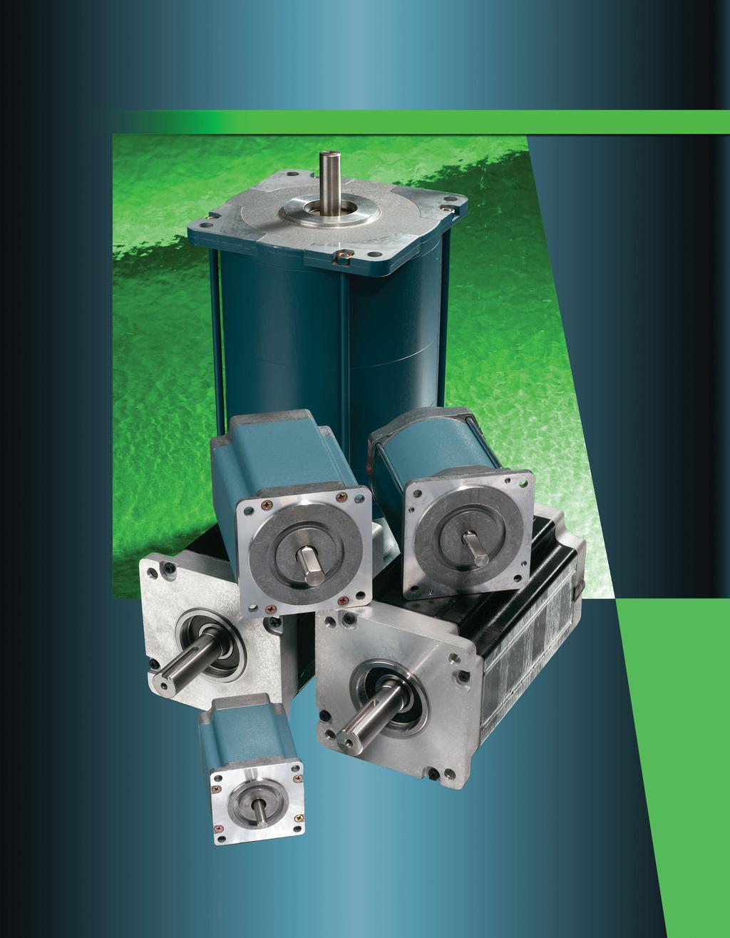
2 Danaher Motion and Superior Electric Superior Electric is a Danaher Motion brand, and is recognized worldwide as the leading manufacturer of synchronous motors. Over 40 years ago, Superior Electric developed and patented their synchronous motors. The Superior Electric family of automation products includes: Step Motors Step Motor Drives Motion Controls Synchronous Motors This catalog highlights the latest selection of high torque synchronous motors from Superior Electric. Our new line of NEMA size 4 high torque motors complements and extends the range of our size and 4 high torque motors. These motors provide worldclass performance, and represent the best value of any lineup ever offered by Superior Electric. They provide twice the torque (and in some cases more than twice the torque) of older conventional synchronous motors. Table of Contents Your partner in Motion Control Danaher Motion offers a comprehensive line of motors, drives, controls, and actuators designed to optimize the performance of motion control systems. These address a wide array of requirements, ranging from simple repetitive moves to complex multiaxis motion. Ongoing product development enables Danaher Motion to provide innovative, leading edge solutions to our customers. One of the best reasons to select a Superior Electric product is Danaher Motion's superior service and support. Our products are available globally through the industry s most extensive and experienced distributor network. These trained distributors provide valuable technical assistance, in addition to fast delivery and service. A team of application engineers backs our distributor network. The combined experience of this support system ensures that our customers receive prompt, quality attention to their needs, no matter where they are located. Danaher Motion has extensive experience customizing motors to meet specific design requirements. Our engineering staff will work with you to achieve your product performance goals. Further assistance and support is provided on the web at Visitors to this site will find product information, technical specifications, and information on our distribution network. Introduction to Synchronous Motors Synchronous Motor Characteristics 45 KS06, KS09, KS11 Series High Torque NEMA, 4, 4 69 SS40, SS4 Series NEMA Size Hazardous Duty Motors NEMA Sizes 4, Phase Shifting Components 17 Gearbox Kits & Gearmotors 180 Application Assistance 1 Conversion Factors


3 Introduction to Synchronous Motors These motors offer substantial advantages in applications needing their very unique capabilities. High Torque Motor Construction Rugged Square Frame Construction Reliable High Temperature Insulation Special All Copper Windings Leads Locked in Place Superior Electric synchronous motors are high pole count motors that naturally turn at slower speeds (7 or 60 rpm). They only need a resistor capacitor (RC) network to operate from singlephase AC utility power. For loads that operate at 7 RPM or slower, they are very cost effective and simple to use. Other motor technologies (induction, DC, servo and step motors) either need gear reducers, or electronic drives to match the speed of Superior Electric synchronous motors. The cost of just the gear reduction or the cost of the electronic drive will usually exceed the total cost of the Superior Electric synchronous motor. For even slower speeds planetary gear reducers are offered. Superior Electric synchronous motors produce very low speeds with only modest gear reductions. Performance Features 7 rpm motor speed (with 60 Hz voltage) 60 rpm motor speed (with Hz voltage) Constant speed does not vary with the load 10 volt or 40 volt AC models Torques: 70 to 1,0 ozin (1,069 Ncm) Gear reducers with ratios up to 15:1 and torques up to 5,000 ozin (,670 Ncm) UL and CE hazardous duty versions Fast starting, stopping, or reversing Can be stalled indefinitely without overheating Stainless Steel Shaft Long Life Double Shielded Ball Bearings Typical Applications Due to their ease of use and inherent slow speeds, Superior Electric synchronous motors are used in a wide variety of applications including: Stirring Valve operation Metering pumps Cryogenic pumps Simple position & process controls Linear actuators Edge guides Variable transformers Dampers Conveyor systems Table lifts Remote control of switches, antennas, etc. Robust Brushless Design Laminated Rotors with Permanent Magnets Screw for Ground Connection

4
5 Synchronous Motor Characteristics (Continued) Speed Versus Frequency Speed Frequency (Hertz) 7 rpm at 60 Hertz Models The speed of a synchronous motor is directly proportional to the applied frequency, as shown in the Speed vs. Frequency chart. However, because the winding impedance is also a function of frequency it is necessary to adjust the voltage, to provide a constant current and torque at different excitation frequencies. Holding Torque The permanent magnet construction of a Superior motor provides a small residual torque which helps hold the motor shaft in position when the motor is deenergized. When additional holding torque is required, DC current can be applied to one winding when the ac input is removed. DC current can also be applied to both windings if more holding torque is needed. The diagrams show typical connections for applying DC current to increase holding torque. Contact factory for voltage, current and holding torque specifications. Typical Connections for Applying DC Current to Increase Holding Torque CW OFF RED R 1 The voltage required at a specific frequency can be obtained from the Voltage vs. Frequency curve. When a twophase motor is operated from a twophase source or a threephase motor is operated from a threephase source, it is only necessary to change the voltage and frequency to obtain the desired synchronous speed. When operating from a singlephase source it is necessary to change the values of the phase shifting components at each new frequency to provide the required phase shift. VOLTS PER PHASE (10VOLT MOTORS) Typical Voltage Versus Frequency for a Superior Motor Speed (rpm) Frequency (hertz) VOLTS PER PHASE (40VOLT MOTORS) AC LINE DC SUPPLY CCW RELAY C BLACK WHITE

 Phase Shifting Components Torque (min) # Load Inertia Wiring Resistor(s) Capacitator (40 VAC) amps")

6 KS06, KS09, KS11 Series High Torque 60mm, 90mm, and 110mm Frame Sizes (NEMA Sizes, 4, 4) Latest high torque construction Motor torque up to 10 ozin (1059 Ncm) 7 60 Hz 60 Hz 10 and 40 volt AC versions Patented RRC network for smoother operation Leaded or terminal box connections Gearboxes available on KS09, NEMA 4 motors See pages 18 & 19 for ratings KS11 KS09 KS06 KS * Type Number L T L Leaded T Terminal box NEMA 09 NEMA 4 11 NEMA 4 10 Volt, 60 Hz, Single Phase, 7 RPM 1 # of Stacks IE Motor Length T1 T T1 10 Volts T 40 Volts W X Y W 60 Hz X Hz Y /60 Hz E Rear Shaft G Gearbox + Ratio (KS09 NEMA size 4 motors only) Phase Shifting Components Torque (min) # Load Inertia Wiring Resistor(s) Capacitator (40 VAC) amps ozin Ncm lbin kgcm Diagram Kit Number ohms watt Kit Number µf ^KS 061T1Y R/R/C KS 061T1Y R/C , KS 06T1Y R/C KS 06T1Y R/C KS 091T1Y R/C KS 09T1Y R/C KS 09T1Y R/C KS 111T1W R/C KS 11T1W 1, R/C KS 11T1W 1,0 1, R/C ^ Use this RRC phase shifting arrangement if very smooth operation is desired.
7 KS06, KS09, KS11 Series (Continued) KS11 KS09 KS06 40 Volt, 60 Hz, Single Phase, 7 RPM Phase Shifting Components * Type Number Torque (min) # Load Inertia Wiring Resistor(s) Capacitator (70 VAC) amps ozin Ncm lbin kgcm Diagram Kit Number ohms watt Kit Number µf KS 06TY R/R/C , KS 06TY R/R/C , KS 091TY R/R/C KS 09TY R/C , KS 09TY R/C KS 111TW R/C KS 11TW 1, R/C KS 11TW 1,0 1, R/C KS11 KS09 KS06 40 Volt, Hz, Single Phase, 60 RPM * Type Number Phase Shifting Components Torque (min) # Load Inertia Wiring Resistor(s) Capacitator (70 VAC) amps ozin Ncm lbin kgcm Diagram Kit Number ohm watt Kit Number µf KS 06TY R/R/C , KS 06TY R/R/C , KS 091TY R/R/C KS 09TY R/R/C KS 09TY R/R/C KS 111TX R/C KS 11TX 1, R/C KS 11TX 1,0 1, R/C # This is the maximum rigidly attached load inertia the motor will reliably start. If the load is attached to the motor with a coupling that has a 5º flex, the motors can start loads up to seven times listed. Connection Diagrams AC INPUT CW CCW R/C Connection C RED R 1 BLACK GROUND SCREW AC INPUT CW CCW R/R/C Connection R C R RED BLACK 1 GROUND SCREW WHITE NOTE: 1 Direction or rotation is determined when viewed from end opposite mounting surface. SinglePhase Operation WHITE Number in diagrams represent terminal connection when motors are supplied with terminal boards. TwoPhase Operation 7
8 KSL06 Leaded.4 [56.9] MAX [47.14] 4X 1.48 [7.6].7±.04 [19.1±1.1] 4 MTG HOLES Ø.05 [5.1] MAX. LENGTH KSL061 SERIES.1 [56.1] KSL06 SERIES.06 [77.7] KSL06 SERIES 4.06 [10.1].1 [5.].81±.0 [0.±.51].688±.010 [17.5±0.5] USABLE FLAT Ø.0 [6.].495 [6.7] Ø.0 [6.].495 [6.7] SEE NOTE.00 [.051] A Ø 1.0±.00 [8.10±0.06].00 [.077] A.95 (4.95].09 RAD MAX Ø.15 [7.98].10 [7.95] #440 GND SCREW WHEN APPLICABLE DOUBLE ENDED SHAFT 1" [05] MIN LEAD LENGTH # AWG P0.5MM ].05 [1.] NOTE: SEE SHAFT DETAIL FOR 6 SERIES.00 [.077] A 6 SHAFT DETAIL KST06 Terminal Box MAX. LENGTH KST061 SERIES.41 [86.6] KST06 SERIES 4.6 [108.] KST06 SERIES 5.6 [1.6] REMOVABLE COVER FOR ACCESS TO # AWG [0.5mm ] LEADS. 14 NPT Dimensions are shown in inches (mm) KSL11 Leaded 4 MTG HOLES ø.8 [8.] 4.5 [109.85].0 [88.90] KST11 Terminal Box 1.5 ±.06 [1.75 ± 1.5] ø.00 [1.700].4995 [1.687] DOUBLE ENDED SHAFT MAX. LENGTH KSL111 SERIES.89 [98.81] KSL11 SERIES 5.91 [1.1] KSL11 SERIES 7.9 [01.].48 [1.19] 1" [05] MIN LEAD LENGTH #18 AWG [ 0.96 mm ] MAX. LENGTH KST111 SERIES 5.0 [1.1] KST11 SERIES 7. [18.4] KST11 SERIES 9. [4.4].06 [1.5].19 [.6] 1.75 [4.9] ø [19.0] [19.07] ø.186 ±.00 [ø.54 ± 0.051] [1.08] [0.65] [4.76] [4.71] 8 Dimensions are shown in inches (mm)
9 KSL09 Leaded.65 [69.60] 1.19±.04 MAX. LENGTH 1.19±.0 [0.±1.1] KSL091 SERIES.57 [65.1] [0.±0.60].740 [69.60] KSL09 SERIES.77 [95.6] 1.00 KSL09 SERIES 4.97 [16.0] 4x.4 [5.4] [56.9].19 [4.8] USABLE 4 MTG. HOLES FLAT Ø. [5.66] R.09 [.9] #6 GND SCREW Ø.7 [9.].745 [9.51] DOUBLE ENDED SHAFT 1" [05] MIN LEAD LENGTH #18 AWG [0.96mm ] "C".06 [1.60].000 [.77] A "B".00 [.051] A Ø.875±.00 [7.0±0.06].000 [.77] A Motor Series KS 091 KS 09 KS 09 Shaft Dimensions "B" Dia. "C" Flat in mm in mm KST09 Terminal Box MAX. LENGTH KST091 SERIES.90 [100] KST09 SERIES 5.10 [10] KST09 SERIES 6.0 [161] REMOVABLE COVER FOR ACCESS TO #6 TERMINALS KS09 Gearmotors See pages 18 & 19 or gearbox information Motor Series KS 091 KS 09 KS 09 Gearbox Ratio :1 thru 5:1 9:1 thru 5:1 7:1 thru 15:1 :1 thru 5:1 9:1 thru 5:1 7:1 thru 15:1 :1 thru 5:1 9:1 thru 5:1 7:1 thru 15:1 Dimensions are shown in inches (mm) B NPT "A" MAX.0 [5.11] MIN Leaded Series KSL091 KSL09 KSL09 "B" MAX.5 MAX [6.5] #405 WOODRUFF KEY SUPPLIED.41 [10.49].0 [1.7].498 [1.64] C Leaded Motors A Ø.91 [7.9] MAX 1.10 [7.94] MIN LENGTH Ø (0)[1.7] 1.79±0.0 [45.47±0.77].56 [14.].57 [14.48].15 [.18].10 [.].001 [0.05] C.6 [8.81] MAX Ø.9 [86.11] MAX. X Ø 0. [5.66] THRU 180 APART ON A Ø.88 [98.] Terminal Box Motors Terminal A Motors KST091 KST09 KST www.DanaherMotion.com

10 SS40,SS4 Series 90mm Frame Size (NEMA Sizes, 4, 4) Motor torque up to 4 ozin (1059 Ncm) 7 60 Hz 60 Hz 10 and 40 volt AC versions Needs only a capacitor to operate from singlephase power Available with integral capacitor for single phase operation Operates directly from threephase power Leaded, connector or terminal box connections Planetary gearboxes available See pages 18 and 0 SS G Gearbox + Ratio Volt, 60 Hz, Single Phase, 7 RPM * Type Number voltage Torque in ozin, and Last # indicates Voltage 1 10 Volts 40 Volts SS41 = 40 ozin, 10 V SS45 = 4 ozin, 40 V L Leads Base offering T Terminal Box (blank) Connector on Leads C Covered Capacitor CT Capacitor in Terminal Box E Rear Shaft Phase Shifting Torque (min) # Load Inertia Wiring Capacitator ( VAC) amps ozin Ncm lbin kgcm Diagram Kit Number µf SS C SS C Volt, 60 Hz, Single Phase, 7 RPM * Type Number voltage Phase Shifting Torque (min) # Load Inertia Wiring Capacitator ( VAC) amps ozin Ncm lbin kgcm Diagram Kit Number µf SS4 08/ C 0108 SS45 08/ C Volt, Hz, Single Phase, 60 RPM * Type Number voltage Phase Shifting Torque (min) # Load Inertia Wiring Capacitator ( VAC) amps ozin Ncm lbin kgcm Diagram Kit Number µf SS C 0108 SS C SS45 0/ C
11 SS40, SS4 (Continued) Three Phase, Volt, 60 Hz, 7 RPM * Type Number voltage Torque (min) # Load Inertia Wiring amps ozin Ncm lbin kgcm Diagram SS4 08/ Ø SS Ø Three Phase, 08 Volt, Hz, 60 RPM * Type Number voltage Torque (min) # Load Inertia Wiring amps ozin Ncm lbin kgcm Diagram SS Ø SS Ø Connection Diagrams Terminations Lead Color Connector Motor Terminal Box Motor INPUT LINE SINGLE PHASE CW CCW C Connection OFF RED BLACK WHITE DIRECTION OF ROTATION DETERMINED WHEN VIEWED FROM NAMEPLATE END OF MOTOR. MOTOR FOR SINGLE PHASE OPERATION SinglePhase Operation Mating Connector with Leads Part number 501 Mating connectors with 6 (914mm) long leads are available for making connections to motors that have connectors. Red Pin # 7 Terminal # 1 Black Pin # 6 Terminal # White Pin # Terminal # PHASE A (RED) PHASE B (BLACK) PHASE C (WHITE*) INPUT LINE PHASE CONNECTOR AMP # TERMINAL AMP # " (914 mm) Ø Connection CCW CW RED BLACK WHITE DIRECTION OF ROTATION DETERMINED WHEN VIEWED FROM NAMEPLATE END OF MOTOR. * WHITE IS NOT "NEUTRAL". ThreePhase Operation
12 SS40, SS4 (Continued) Leaded Motor Motor Type SS41L SS41LE SS4L SS4LE SS451L SS451LE SS45L SS45LE A Terminal Box Motor Type SS41T SS4T SS451T SS45T Connector A Motor Type SS41 SS41E SS4 SS4E SS451 SS451E SS45 SS45E Dimensions are shown in inches (mm)
13 Covered Capacitor Motor Type SS41C SS4C SS451C SS45C A Capacitor in Terminal Box Motor Type SS41CT SS4CT SS451CT SS45CT A Gearmotors See pages 18 and 0 for gearbox information Motor Series SS40 SS4 Leaded & Connector Motors Terminaol Box Motors Covered Capacitor Motors Capacitor in Terminal Box Motors B Gearbox Ratio Connector A A A B Leaded Motors Motor Type Motor Type Motor Type Motors :1 thru 5: S41LG SS41G SS41TG SS41CG SS41CTG 9:1 thru 5: SS4LG SS4G SS4TG SS4CG SS4CTG 7:1 thru 15: :1 thru 5: SS451LG SS451G SS451TG SS451CG SS451CTG 9:1 thru 5: SS45LG SS45G SS45TG SS45CG SS45CTG 7:1 thru 15: Dimensions are shown in inches (mm)

14 Ex d IIC T5 11 G Ex d IIC T5
15 Hazardous Duty Motors (Continued) 10 Volt, 60 Hz, Single Phase, 7 RPM Phase Shifting * Type Number Torque (min) # Load Inertia Wiring Resistor Capacitor (0VAC) amps UL CE ozin Ncm lbin kgcm Diagram Kit Number ohms watts Kit Number µf X XCE RC X700 XCE RC X1100 XCE1100 1, RC X10 XCE10 1,0 1, RC Volt, 60 Hz, Single Phase, 7 RPM Phase Shifting * Type Number Torque (min) # Load Inertia Wiring Resistor Capacitor (660VAC) amps UL CE ozin Ncm lbin kgcm Diagram Kit Number ohms watts Kit Number µf X5 XCE RC XCE RC X110 XCE110 1, RC X1 XCE1 1,0 1, RC Volt, Hz, Single Phase, 60 RPM Phase Shifting * Type Number Torque (min) # Load Inertia Wiring Resistor Capacitor (660VAC) amps UL CE ozin Ncm lbin kgcm Diagram Kit Number ohms watts Kit Number µf X5 XCE RC XCE RC X110 XCE110 1, RC X1 XCE1 1,0 1, RC # This is the maximum rigidly attached load inertia the motor will reliably start. If the load is attached to the motor with a coupling that has a 5º flex, the motor can start loads up to seven times listed. Connection Diagram AC INPUT CW CCW R/C Connection WHITE C RED R 1 BLACK NOTE: 1 Direction or rotation is determined when viewed from end opposite mounting surface. SinglePhase Operation GROUND SCREW
16 Hazardous Duty Motor Dimensions X, X5, X700, XCE, XCE5, XCE700, XCE Motor Series A Max. B Max. C Max. X X XCE XCE X XCE700 XCE Dimensions are shown in inches (mm) X1100, X110, X10, X1, XCE1100, XCE110, XCE10, XCE1 16 Motor Series A Max. X1100 X XCE1100 XCE X10 X XCE10 XCE Dimensions are shown in inches (mm)
17 Phase Shifting Components Capacitor Kits PHASE SHIFTING COMPONENT DIMENSIONS D A B Resistor Kits A. [ 1.7 ] min. clearance required above terminals. B FIGURE C1 FIGURE C C.18 [ 4.6 ] dia. hole B C D Kit Number Figure µfd VAC C C C C C C C C C1 010 C C 0108 C C 0104 C C C 0106 C C C C C C C C C C C C Kit Number ohms watts * * * * * * , , , , A B C D in mm in mm in mm in mm A B C in mm in mm in mm * Kit contains two resistors. Dimensions shown are for one resistor.
18 Gearbox Kits & Gearmotors Ratios from :1 to 15:1 Up to 5,000 ozin (, Ncm) torque 1 lb (68 kg) radial load capacity 100 lb (45 kg) axial load capacity Typical output shaft backlash is (degrees) Maintenance free Kits for field installation to NEMA 4 motors Superior Electric gearmotors mate NEMA 4 synchronous motors with stepdown gearboxes for applications where slow shaft speeds or high torque are needed. The rugged gearbox developed for Superior gearmotors has been designed to allow high output torque ratings, while providing long life. The gearboxes are permanently lubricated and no scheduled maintenance is needed. Gearbox efficiency is 88% to 68% depending on the number of stages. The output shaft of the gear assembly is provided with a standard Woodruff key for easy and positive coupling to the load. Gearbox Kits Gearbox (G) Ratio Kit PartNumber "B" Body length.0 [5.11] MIN Typical Input Shaft Lost Motion * Note: Gearboxes for KS09 motors must be installed at the factory..5 MAX [6.5] #405 WOODRUFF KEY SUPPLIED.0 [1.7].498 [1.64] C Typical Output Shaft Backlash 1.10 [7.94] MIN LENGTH Ø (0)[1.7] 1.79±0.0 [45.47±0.77].56 [14.].57 [14.48] Reflected Momen of Inertia.15 [.18].10 [.].001 [0.05] C In mm Degrees Degrees LbIn KgCm : % 4: % 5: % 9: % 1: % 15: % 16: % 0: % 5: % 7: % 6: % 45: % 48: % 60: % 64: % 75: % 80: % 100: % 15: % "B" MAX.41 [10.49] Ø.91 [7.9] MAX.6 [8.81] MAX Ø.9 [86.11] MAX. X Ø 0. [5.66] THRU 180 APART ON A Ø.88 [98.] Efficiency
19 KS09 Gearmotor Ratings See pages 69 for motor information Gearmotor Model Gear Ratio Speed (RPM) Torque (min) Maximum Rigidly Attached Load Inertia 1 Phase, 60 Hz 1 Phase, Hz 10 Volt Hz ozin Ncm lbin kgcm lbin kgcm KSL091T1YG KSL091TYG : KSL091T1YG4 KSL091TYG4 4: KSL091T1YG5 KSL091TYG5 5: , KSL091T1YG9 KSL091TYG9 9: ,66 1, KSL091T1YG1 KSL091TYG1 1:1 6 5,18 1, , ,447 KSL091T1YG15 KSL091TYG15 15: ,77 1, , ,69 KSL091T1YG16 KSL091TYG16 16: ,957, ,86 880,574 KSL091T1YG0 KSL091TYG0 0:1.6,696,610 1,5,584 1,79 4,05 KSL091T1YG5 KSL091TYG5 5: ,60,6 1,914 5,60,1 6,06 KSL091T1YG7 KSL091TYG7 7: ,406,11 1,96 5,67,174 6,6 KSL091T1YG6 KSL091TYG6 6: ,000,,489 10,09,90 11,498 KSL091T1YG45 KSL091TYG45 45: ,000, 5,475 16,00 6,16 18,04 KSL091T1YG48 KSL091TYG48 48: ,000, 6,09 18,167 6,99 0,459 KSL091T1YG60 KSL091TYG60 60: ,000, 9,76 8,487 10,960,068 KSL091T1YG64 KSL091TYG64 64: ,000, 11,08,97 1,41 6,7 KSL091T1YG75 KSL091TYG75 75: ,000, 15,16 44,5 17,18,118 KSL091T1YG80 KSL091TYG80 80: ,000, 17,08,64 19,484 57,010 KSL091T1YG100 KSL091TYG : ,000, 7,0 79,149 0,4 89,098 KSL091T1YG15 KSL091TYG15 15: ,000, 4,66 1,671 47,579 19,15 KSL09T1YG KSL09TYG : , KSL09T1YG4 KSL09TYG4 4: ,584 1, KSL09T1YG5 KSL09TYG5 5: ,980 1, KSL09T1YG9 KSL09TYG9 9: ,119,0 49 1, ,49 KSL09T1YG1 KSL09TYG1 1: ,158,96 88,58 88,58 KSL09T1YG15 KSL09TYG15 15: ,000, 1,8 4,04 1,8 4,04 KSL09T1YG16 KSL09TYG16 16: ,000, 1,570 4,59 1,570 4,59 KSL09T1YG0 KSL09TYG0 0:1.6 5,000,,457 7,189,457 7,189 KSL09T1YG5 KSL09TYG5 5: ,000,,89 11,4,89 11,4 KSL09T1YG7 KSL09TYG7 7: ,000,,909 11,48,909 11,48 KSL09T1YG KSL09TYG : ,848 1, KSL09T1YG4 KSL09TYG4 4: ,464 1, KSL09T1YG5 KSL09TYG5 5: ,080, KSL09T1YG9 KSL09TYG9 9: ,851,46 804,51 866,54 KSL09T1YG1 KSL09TYG1 1: ,000, 1,47 4,04 1,548 4,59 19 Continued on next page.
20 SS40, SS4 Gearmotor Ratings See pages 101 for motor information Gearmotor Model Gear Ratio Speed (RPM) Torque (min) Maximum Rigidly Attached Load Inertia 1 Phase, 60 Hz 1 Phase, Hz Phase 10 Volt Hz ozin Ncm lbin kgcm lbin kgcm lbin kgcm SS41LG SS4LG : SS41LG4 SS4LG4 4: SS41LG5 SS4LG5 5: , SS41LG9 SS4LG9 9: ,66 1, SS41LG1 SS4LG1 1:1 6 5,18 1, SS41LG15 SS4LG15 15: ,77 1, , , SS41LG16 SS4LG16 16: ,957, , ,41 SS41LG0 SS4LG0 0:1.6,696,610 76, , SS41LG5 SS4LG5 5: ,60,6 1,19, ,77 1,19,489 SS41LG7 SS4LG7 7: ,406,11 1,18, ,85 1,18, SS41LG6 SS4LG6 6: ,000,,167 6,41 845,47,167 6,41 SS41LG45 SS4LG45 45: ,000,,409 9,976 1,44,9,409 9,976 SS41LG48 SS4LG48 48: ,000,,859 11,91 1,9 4,415,859 11,91 SS41LG60 SS4LG60 60: ,000, 6,064 17,74,9 6,998 6,064 17,74 SS41LG64 SS4LG64 64: ,000, 6,860 0,07,68 7,848 6,860 0,07 SS41LG75 SS4LG75 75: ,000, 9,478 7,74,741 10,946 9,478 7,74 SS41LG80 SS4LG80 80: ,000, 10,780 1,54 4,5 1,441 10,780 1,54 SS41LG100 SS4LG : ,000, 16,8 49,04 6,6 19,459 16,8 49,04 SS41LG15 SS4LG15 15: ,000, 6,9 77,08 10,91 0,405 6,9 77,08 SS451LG SS45LG : , SS451LG4 SS45LG4 4: ,584 1, SS451LG5 SS45LG5 5: ,980 1, SS451LG9 SS45LG9 9: ,119, SS451LG1 SS45LG1 1: ,158, , ,447 SS451LG15 SS45LG15 15: ,000, 949, ,00 775,69 SS451LG16 SS45LG16 16: ,000, 1,077, ,1 880,574 0 SS451LG0 SS45LG0 0:1.6 5,000, 1,687 4, ,78 1,79 4,05 SS451LG5 SS45LG5 5: ,000,,66 7,714 95,785,1 6,06 SS451LG7 SS45LG7 7: ,000,,670 7,81 95,76,174 6,6
21 Application Assistance Parallel Motor Operation Two or more Superior motors may be operated simultaneously from the same power source, if the total current requirement does not exceed the current capability of the supply. However, due to the motor starting characteristics, mechanical synchronization of the motors is not practical. As described under Starting And Stopping Characteristics, one motor may achieve running speed within 5 milliseconds while a second motor, because of its at rest position, may require 5 milliseconds to achieve running speed. Starting High Inertia Loads The motor charts show the maximum load inertia that each motor model can start. Inertial loads as high as five to ten times these ratings can be started if a flexible coupling is used between the motor shaft and the load. The coupling should allow approximately 5 of shaft rotation before the full load is applied to the shaft. Rubber couplings are often used, as are chain drives with sufficient slack to allow the necessary shaft motion. Timing belts are also used, and in most cases will provide adequate flexing while providing smooth and quiet transmission of power. Effects of Speed Reduction Gearing on Torque and Inertia The combination of reduction gearing and a Superior motor provides increased torque as well as a lower operating speed. Output speed is decreased and torque increased by the factor of the gear ratio used minus losses due to gear train inefficiency. Gear losses are typically around 10% per mesh. Stepdown gearing offers even greater gains in inertial load rating, since the inertia moving capability increases by the square of the gear ratio. Timing belts and pulleys can be used in place of gears for speed reduction and will provide the added benefit of a flexible coupling. Coupling Motor to Load Because of the extremely fast starting and stopping characteristics of a Superior AC synchronous motor, couplings, pulleys or other devices should be well secured to the motor shaft with the key provided, rollpins, or setscrews. If a coupling is to be pressfitted to the shaft, the motor must be held by the shaft (not by the gearbox or the motor case) when pressing the coupling in place. This will prevent damage to the motor bearings. The force used in pressing must not exceed the thrust force limit of the gearbox (100 pounds). Switch Contact Protection In some applications it may be desirable to protect the switch contacts from arcing and from transient voltages generated during switching. The most common method is the addition of resistors and capacitors across the switch contacts as shown in the diagram. Recommended values of the components are: resistor, 0 ohm, 1 watt; capacitor, 0.1 mfd, Vac. INPUT LINE CONTROL SWITCH CW OFF CCW RED BLACK WHITE 1 MOTOR SWITCH PROTECTION NETWORK FOR AC OPERATION OF STANDARD MODELS Temperature Considerations The motors are rated for a maximum freeair ambient temperature of 40 C (104 F). However, it is possible to operate in higher ambient temperatures or above rated voltages if the motors are mounted on metal plates or are forcedair cooled. Do not exceed the maximum motor case temperature of 100 C (1º F). Maximum Shaft Loads Motor Series Radial lb kg Maximum Shaft Loads Axial lb kg KS KS KS09 Gearmotors KS SS40, SS SS40, SS4 Gearmotors X, XCE 5 11 X700, XCE X1100, XCE X10, XCE
22 Application Assistance (continued) How to Select an AC Motor Gears and Pulleys To select a synchronous motor first determine the torque and moment of inertia characteristics of the load, as presenteed to the motor. The following examples show how to calculate these requirements in both standard U.S. and metric units. Once the requirements of the application including input voltage and frequency are known, refer to the ratings shown on the motor charts and select the motor which best suits these requirements. If additional information or technical assistance is needed, contact Superior Electric. A representative will be pleased to help you select the best motor for your application. Torque Torque (ozin) = Fr Where F = Force (in ounces) required to drive the load r = Radius (in inches) Force can be measured using a pull type spring scale. The scale may be attached to a string that is wrapped around a pulley or a hand wheel attached to the scale. If the scale reading is in pounds, it must be converted into ounces to obtain a torque rating in ounceinches. For example: A 4 diameter pulley requires a pound pull on the scale to rotate it. F = pounds x 16 = ounces r = 4" = " Torque = x = 64 ozin Torque (Ncm) = Fr Where F = Force (N) required to drive the load r = radius (in cm) Force can be measured using a pull type spring scale. If the scale reading is calibrated in kilograms, the scale reading must be multiplied by to obtain newtons. The scale should be attached to a string that is wrapped around a pulley or a hand wheel which is then attached to the load. For example, a 10 cm diameter pulley requires a 1.5 newton (0.15 kg) pull on the scale to rotate it. F = 1.5 newtons r = 5 cm Torque = 1.5 x 5 = 7.5 Ncm r When the load is driven through gears or pulleys, the required motor torque is changed by the overall ratio. For example, if the load is 90 ounceinches (6.6 Ncm) and the stepdown ratio is :1, the required torque would be 0 ounceinches (1. Ncm). Load inertia presented to the motor is changed by the square of the ratio. For example, with a load inertia of 4 poundinches (11.71 kgcm ) and a :1 stepdown ratio, the effective inertia would be 1 poundinch (.9 kgcm ) plus the inertia of the first gear or pulley. Inertia Moment of Inertia (lbin ) (lbin )= Where W = Weight in pounds r = Radius in inches For example: A load is a 8 diameter gear weighing 8 ounces W = 8 16 =.05 pounds r = 8" = 4" Moment Of Inertia = 0.5 x (4) = 4 lbin Moment Of Inertia (kgcm ) Where W = newtons r = cm For example: A load is a 0 cm diameter gear weighing 0.5 newtons. W =.5 newtons r = 10 cm Moment Of Inertia = 0.5 x 10 = 1.75 kgcm W Wr J= Wr for a disk for a disk or (lbin )= W (r1 r) for a cylinder or J = W (r 1 r ) for a cylinder W F r r 1 r
23 Conversion Factors Length* B A mm cm m inch feet mm ===== cm 10 ===== m ===== inch ===== 0.08 feet ===== *Multiply units of "A" by indicated factor to obtain units of "B". Force* B A g kg oz lb Newton g ===== kg 1000 ===== oz ===== lb ===== Newton ===== *Multiply units of "A" by indicated factor to obtain units of "B". Inertia* A B kgm kgcm gcm ozin ozinsec lbin lbinsec lbft lbftsec (slug ft) kgm ===== 1.00 x x x x x x 10 1 kgcm 1.00 x 10 4 ===== 1.00 x x x x x x 10 5 gcm 1.00 x x 10 ===== x x x x x ozin 1.89 x x x 10 =====.590 x x x x x 10 5 ozinsec 7.06 x x x 10 ===== x x x 10 lbin.96 x x x x 10 =====.590 x x x 10 4 lbinsec 1.10 x x x x x 10 ===== x 10 lbft 4.14 x x x x x x 10 1 =====.180 x 10 lbftsec (slug ft) x x x x x ===== *Multiply units of "A" by indicated factor to obtain units of "B". Torque* B A Nm Ncm dyn cm kgm* kgcm* gcm* ozin lbft lbin Nm ===== 1.00 x x x x x x Ncm x 10 ===== x x x x x x 10 dyn cm x x 10 5 ===== 1.00 x x x x x x 10 7 kgm** x x 10 7 ===== x x x kgcm** x x x 10 ===== x x x 10 1 gcm** x x x x x 10 ===== 1.89 x x x 10 4 ozin 7.06 x x x x x ===== 5.8 x x 10 lbft x x x x x 10 ===== 1 lbin 1.10 x x x x x 10 ===== *Multiply units of "A" by indicated factor to obtain units of "B". ** Sometimes written as kpm, kpcm, and pcm, respectively, to denote the force equivalent of the kg and g mass.

24 Distribution CoastToCoast and International The Superior Electric brand is a global leader in the engineering, manufacturing, and marketing of precision motion and control products for industrial applications. All Superior motors and controls are backed by highly specialized engineers and service people who can help solve your production challenges. Superior Electric s capabilities and products have improved operations for companies around the world. Through Danaher Motion's extensive authorized distributor network, Superior Electric products are available worldwide. These distributors provide convenient services by offering technical support, replacement parts, and literature, as well as an extensive inventory of models offtheshelf for the fastest possible delivery. Call Superior Electric customer service for ordering and application information or for the address of the nearest authorized distributor for Superior Electric products. Danaher Motion Customer Support Center 10J South Point Blvd. Charlotte, NC 87 Tel: Fax: Support sales@danahermotion.com Web: In Europe Danaher Motion GmbH & Co. KG RobertBoschStraße Weiterstadt, Germany Tel: +49 (0) Fax: +49 (0) Internet: 10J South Point Blvd. Charlotte, NC 87 U.S.A. TEL: FAX: Superior Electric Printed in U.S.A. SP15,00008/00 SUP010S101
Artisan Scientific is You~ Source for: Quality New and Certified-Used/Pre:-awned ECJuiflment
 Looking for more information? Visit us on the web at http://www.artisan-scientific.com for more information: Price Quotations Drivers Technical Specifications. Manuals and Documentation Artisan Scientific
AC Synchronous Motors
 AC Synchronous Motors A C S Y N C H R O N O U S M O T O R S AC Synchronous Motors Kollmorgen AC synchronous motors are high pole count motors that naturally turn at slower speeds (72 or 60 rpm). They only
CT Series Step Motors
 CT Series Step Motors CT Series Step Motors Table of Contents Introduction.................................................................................................. 4 Construction................................................................................................
Product Overview. Hansen Precision Electric Motors DC AC DC. Actuators. Stepper
 AC Hansen Precision Electric Motors Hansen s quality products are known around the world. These include: Synchron Motors, available with custom voltage, speed and power, durable brush motors, AC clock
Induction Motors. Standard AC Motors. Constant Speed Motors. Standard AC Motors C-19. Induction Motors
 Standard AC Introduction Induction Induction Standard AC Constant Speed Induction Reversible Electromagnetic Brake Clutch & Synchronous Brake Low-Speed Synchronous Watertight, Dust-Resistant Gearheads
SLM/SLG SERIES. SLM Series Motors/SLG Series Gearmotors BRUSHLESS AC OR DC SERVO MOTOR / INTEGRATED SERVO GEARMOTOR
 SLM Series Motors/SLG Series Gearmotors SLM/SLG SERIES BRUSHLESS AC OR DC SERVO MOTOR / INTEGRATED SERVO GEARMOTOR Compatible with virtually any manufacturer s servo drive Multiple frame size options 952.5.62
MOONS SM servo motors offer a great combination of Power, Precision and Value:
 MOONS SM Series of servo motors has been expanded and improved. The SM Series now includes a variety of standard windings, more feedback options, and more connection options. Some ratings have increased,
Reversible Motors. Standard AC Motors. Constant Speed Motors. Standard AC Motors C-75. Reversible Motors
 Standard AC Introduction Induction Standard AC Constant Reversible Reversible Reversible Electromagnetic Brake Clutch & Synchronous Brake Low- Synchronous Watertight, Dust-Resistant Torque Gearheads Linear
BMS Series. DC Brushless Torque Motors. Slotless, brushless stator design provides zerocogging torque for unsurpassed velocity control
 BMS Series Rotary Motors BMS Series DC Brushless Torque Motors Slotless, brushless stator design provides zerocogging torque for unsurpassed velocity control Smoother velocity than with standard DC brushtype
300 & 400 Series Positioning Tables
 300 & 400 Series Positioning Tables 300 Series Introduction L-2 400 Series Introduction L-3 Specifications L-5 300 Series Dimensions L-6 400 Series Dimensions L-7 300 Series Motor Couplings L-8 300 Series
BMS Series. DC Brushless Torque Motors. Slotless, brushless stator design provides zerocogging torque for unsurpassed velocity control
 BMS Series DC Brushless Torque Motors Slotless, brushless stator design provides zerocogging torque for unsurpassed velocity control Smoother velocity than with standard DC brushtype motors with the advantage
EXPERTS IN MOTION CONTROL I N D U S T R I A L P R O D U C T S
 EXPERTS IN MOTION CONTROL I N D U S T R I A L P R O D U C T S COMPANY-WIDE COMMITMENT TO QUALITY At Globe Motors, we re committed to providing customers with products and services that meet or exceed their
Introduction. Remark:
 M O T O R S B R U S H L E S S D C Introduction NMB Minebea is a world leader in the design and manufacture of precision brushless DC motors and stepping motors. The company offers a broad range of standard
Copeland Scroll TM compressors. for commercial applications
 Copeland Scroll TM compressors for commercial applications Contents Page Copeland Scroll TM Story.......................... 2 ZR84K to ZR190K Product Description............................. 5 Features........................................
Low-Speed. Constant Speed Motors. Standard AC Motors A-203. Standard AC Motors Introduction. Low-Speed Synchronous Motors.
 Standard C Constant Speed Low-Speed Synchronous Standard C Introduction Induction Reversible Electromagnetic Brake V Series Clutch & Brake Synchronous Low-Speed Synchronous Low-Speed Synchronous Watertight,
Rotary Series Rotary Series: Direct Drive Precision Stages
 Rotary Series Rotary Series: Direct Drive Precision Stages Parker Bayside s Direct Drive Rotary Stages feature a robust construction and high performance in a compact package, providing smooth, near-frictionless
!Linear & Rotary Positioning Stages. !Servo Motors & Drives. !Gearmotors & Gearheads. GM Series Stealth Planetary Gearmotor Product Manual
 !Linear & Rotary Positioning Stages!Servo Motors & Drives!Gearmotors & Gearheads GM Series Stealth Planetary Gearmotor Product Manual GM Series Stealth Planetary Gearmotor Product Manual Rev: 7.0 / 0305
Servo Motors. Unimotor hd, Unimotor fm, NT Series and XV Series lb-in ( Nm) 230 V 460 V
 230 V 460 V") Servo Motors Unimotor hd, Unimotor fm, NT Series and XV Series 0.9-1204 lb-in (0.11-136 Nm) 230 V 460 V Contents Introduction: A Servo Motor for Every Application... 1 Drive and Motor Selection... 3 Electronic
Servo Motors Unimotor hd, Unimotor fm, NT Series and XV Series 0.9-1204 lb-in (0.11-136 Nm) 230 V 460 V Contents Introduction: A Servo Motor for Every Application... 1 Drive and Motor Selection... 3 Electronic
AC Servo Motors and Servo Rated Gearheads
 AC Servo Motors and Servo Rated Gearheads for the automation industry Brushless Servo Motors 2 AC Servo Motors Baldor has been leading the way in energy efficient industrial motors since the 192 s. Baldor
FAN ENGINEERING. Application Guide for Selecting AC Motors Capable of Overcoming Fan Inertia ( ) 2
 2") FAN ENGINEERING Information and Recommendations for the Engineer Twin City Fan FE-1800 Application Guide for Selecting AC Motors Capable of Overcoming Fan Inertia Introduction Bringing a fan up to speed
FAN ENGINEERING Information and Recommendations for the Engineer Twin City Fan FE-1800 Application Guide for Selecting AC Motors Capable of Overcoming Fan Inertia Introduction Bringing a fan up to speed
M, N and A Series Brushless Servo Motors
 www.applied-motion.com M, N and A Series Brushless Servo Motors Applied Motion s M Series, N Series, and A Series brushless servo motors provide extremely high performance in one of the industry s most
TurboDisc Stepper Motors
 TurboDisc Stepper Motors P43 P532 P31 P11 P1 The TurboDisc provides exceptional dynamic performance unparalleled by any other stepper on the market. The unique thin disc magnet enables finer step resolutions
Gearmotors & Gearheads. Servo Motors & Drives. Linear & Rotary Positioning Stages. Direct Drive Rotary Table Product Manual
 Servo Motors & Drives Gearmotors & Gearheads Linear & Rotary Positioning Stages Direct Drive Rotary Table Product Manual Direct Drive Rotary Table Product Manual Rev: 3.2 / 1103 P/N: 12197009 Please check
ElectroCraft RapidPower Xtreme Brushless DC Servo Motors
 ElectroCraft RapidPower Xtreme Brushless DC Servo Motors Product Datasheets for RPX22 RPX32 RPX4 RPX52 About ElectroCraft is a global provider of dependable, application-engineered fractional-horsepower
High quality nut and screw materials are precisely formed to reduce backlash, increase life, support maximum force, and increase efficiency
 Linear Actuators owerlustechnology...03 Model Number System...04 Basic Styles Lead & Linear Travel...05 Optional Construction & Modifications...06 Size 8 -.8 - Lx08HY Series...07 Size -.8 - LxHS Series...0
Magnetic Particle Brakes and Clutches
 Magnetic Particle Brakes and Clutches Accurate torque control with instantaneous engagement! Available in a wide range of models and sizes Warner Electric s magnetic particle brakes and clutches are quiet
Quantum Series Size 17, 23, 34 and 56 Brushless Servo Motors Frameless and Housed Engineering Guide
 MACCON GmbH Kübachstr.9 D-81543 München Tel +49-89-65122()-21 Fax +49-89-655217 Quantum Series Size 17, 23, 34 and 56 Brushless Servo Motors Frameless and Housed Engineering Guide Selection Guide Quantum
TRAC-3 TENSION READOUT AND CONTROL
 Magnetic Power Systems, Inc. 1626 Manufacturers Drive. Fenton, MO 63026 Tel: 636.343.5550 Fax: 636.326.0608 magpowr@magpowr.com INSTRUCTION MANUAL TRAC-3 READOUT AND CONTROL For Control of Magnetic Particle
Kollmorgen Stepper Motor Overview
 Kollmorgen Stepper Motor Overview K O L L M O R G E N S T E P P E R M O T O R O V E R V I E W Kollmorgen offers a comprehensive range of stepper motor products including continous torque, high torque and
Electromagnetic. Brake Motors. Constant Speed Motors. Standard AC Motors A-109. Standard AC Motors Introduction. Brake Motors
 Standard AC Constant Speed Standard AC Introduction Induction Reversible V Series Clutch & Synchronous Low-Speed Watertight, Synchronous Dust-Resistant Gearheads Page Features and Types of A-11 General
planetroll Planetary Gearheads
 planetroll Planetary Gearheads www.diequa.com 630-980-1133 Overview Planetary Servo Gearheads by Planetroll German Engineered - Ecomically Priced The Planetdrive series of precision planetary servo gearheads
Standard AC Motors C-9
 Standard AC C-9 Overview, Product Standard AC Constant Speed Constant Speed Reversible Reversible Brake Brake Clutch & Brake Clutch & Brake Synchronous Synchronous Torque Watertight, Dust-Resistant Gearheads
Hybrid Stepper Motors
 DINGS Electrical & Mechanical Co., Ltd 3 Quality Performance Flexibility Price WHO IS DINGS? DINGS is a premier supplier of rotary and linear step motors. Based in the greater Shanghai, China area, we
1980 Rotating Cam Limit Switches. Ordering Guide & Technical Information
 1980 Rotating Cam Limit Switches Ordering Guide & Technical Information Features Precision Cam adjustment at any angular position of the Camshaft Speeds from 0 to 500 RPM in either direction No special
Ultra Series: Crossed Roller Ultra Precision Stages
 Ultra Series: Crossed Roller Ultra Precision Stages Bayside Motion Group, has developed Ultra Positioning Stages for applications requiring the ultimate in accuracy. Available with a linear motor, ball
Rotary Direct Drive Motor Cartridge DDR
 www.danahermotion.net Rotary Direct Drive Motor Cartridge DDR Driven by Edition 04.2004 english DDR (Direct Drive Rotary) What is direct drive? Very simply it is the direct coupling of a torque motor to
Standard Street, El Segundo CA BRUSHLESS SERVO MOTORS
 BRUSHLESS SERVO MOTORS To accommodate your complete servo system requirements, Glentek manufactures four complete series (GMB, GMBF, GMBM and GMBN) of high performance, permanent magnet brushless servo
HSI Stepper Motor Theory
 HI tepper Motor Theory Motors convert electrical energy into mechanical energy. A stepper motor converts electrical pulses into specific rotational movements. The movement created by each pulse is precise
Scroll down to view your document!
 Over 1 years cumulative experience 24 hour rush turnaround / technical support service Established in 1993 The leading independent repairer of servo motors and drives in North America. Visit us on the
Why a CanStack motor 118 What is a canstack motor 119 How to select your canstack motor 121 Where to apply your canstack motor 123 Specifications 124
 CANSTACK stepper motors 15M 20M 55M 42M 26M 35M Portescap can trace its roots back to the design team who invented the Permanent Magnet Stepper and AC Synchronous Motor. Today, this technology is found
Motion Solutions AC Induction Permanent Magnet DC Brushless DC
 Motion Solutions AC Induction Permanent Magnet DC Brushless DC Gearmotors Motors Controls bodine-electric.com Your Partner for Engineered Solutions and Optimized Delivery Programs 3D Modeling and Prototyping
Application Information
 Moog Components Group manufactures a comprehensive line of brush-type and brushless motors, as well as brushless controllers. The purpose of this document is to provide a guide for the selection and application
TRUE Planetary Gearheads
 TRUE Planetary Gearheads Danaher Motion - Helping you build a better machine, faster Danaher Corporation combined over 3 industry-leading brands such as Kollmorgen, Thomson, Dover, Pacific Scientific,
CHAPTER 3 DESIGN OF THE LIMITED ANGLE BRUSHLESS TORQUE MOTOR
 33 CHAPTER 3 DESIGN OF THE LIMITED ANGLE BRUSHLESS TORQUE MOTOR 3.1 INTRODUCTION This chapter presents the design of frameless Limited Angle Brushless Torque motor. The armature is wound with toroidal
1326AS Series 460V, Low Inertia, Brushless Servo Motors Product Data
 1326AS Series 46V, Low Inertia, Brushless Servo Motors Product Data This publication provides product information for the.49 to 49.3 N-m (4.33 to 436 lb-in.) 1326AS Series 46V, Low Inertia, Brushless Servo
TRUE Planetary Gearheads
 TRUE Planetary Gearheads Danaher Motion - Helping you build a better machine, faster Danaher Corporation combined over 3 industry-leading brands such as Kollmorgen, Thomson, Dover, Pacific Scientific,
SUB-FHP AC GEARMOTORS PARALLEL SHAFT GEARMOTORS
 SUB-FHP AC GEARMOTORS PARALLEL SHAFT GEARMOTORS 12-100 In-Lbs Single phase gearmotors, totally enclosed for continuous duty, general purpose applications. Permanent TEFC split capacitor designs are rated
Step Motor Drive Products
 Step Motor Drive Products Danaher Motion and Superior Electric Superior Electric is a Danaher Motion brand and is recognized worldwide as the leading manufacturer of step motor drives. Over 40 years ago,
209 Series. Magnetic Circuit Protectors
 29 Series Magnetic Circuit Protectors Introduction 249 Power Selector System Multi-Pole Configurations Operating Characteristics Delay Curves Specifications Decision Tables 73 75 77 79 8 82 85 87 29/29/229/249/279
Electromechanical Rotary Actuator
 Electromechanical Rotary Actuator TYPICAL APPLICATIONS Axis motion control for gimbal and pedestal systems Azimuth, elevation, fold / unfold, leveling control Suitable for airborne and ground based systems
Company Profile.
 SPUR OVOID GEARBOX Company Profile MOONS' is one of the largest integrated manufacturers of motion control products within China, using internationally proven scientific management tools along with the
Surepowr Series Sure 150
 RCS Acutators Surepowr Series Sure 50 Installation Manual Safety First In the maintenance and operation of mechanical equipment, safety is the basic factor which must be considered at all times. Through
Stearns Heavy Duty Clutches & Brakes... Rugged, Reliable
 Stearns Heavy Duty Clutches & Brakes... Rugged, Reliable Stearns heavy duty clutches and brakes represent over 75 years of design, engineering and on-the-job experience. Stearns products are backed by
Data Sheet. Size 1 and 2 Stepper Motors. 7.5 stepper motors Size 1 (RS stock no ) Size 2 (RS stock no ) Data Pack B
 Size 2 (RS stock no ) Data Pack B") Data Pack B Issued November 005 1504569 Data Sheet Size 1 and Stepper Motors 7.5 stepper motors Size 1 (S stock no. 33-947) Size (S stock no. 33-953) Two 7.5 stepper motors each with four 1Vdc windings
Data Pack B Issued November 005 1504569 Data Sheet Size 1 and Stepper Motors 7.5 stepper motors Size 1 (S stock no. 33-947) Size (S stock no. 33-953) Two 7.5 stepper motors each with four 1Vdc windings
Pretest Module 21 Units 1-4 AC Generators & Three-Phase Motors
 Pretest Module 21 Units 1-4 AC Generators & Three-Phase Motors 1. What are the two main parts of a three-phase motor? Stator and Rotor 2. Which part of a three-phase squirrel-cage induction motor is a
Current Controlled Electric Hysteresis Brakes Advantages The superior design of these hysteresis devices provides several inherent advantages over mag
 Current Controlled Hysteresis Brakes Electrically controlled No wearing parts Infinitely adjustable for precise torque/ tension control TRANSMITTING TORQUE THROUGH AIR Current Controlled Electric Hysteresis
KM SERIES HIGH TOR.
 SLO-S O-SYN KM SERIES HIGH TOR ORQUE STEP ORS KM SERIES Superior Electric SLO-SYN long recognized as the leader in step motor technology, has achieved new levels of performance with its high energy KM
with SERVOSTAR CD & 600 drives Systems Technical Publication
 with SERVOSTAR CD & 6 drives s Technical Publication The DDR (Direct Drive Rotary) Story Kollmorgen GOLDLINE DDR What is direct drive? Very simply it is the direct coupling of the torque motor (such as
FRACTIONAL HORSEPOWER MOTORS & ACCESSORIES
 TABLE OF CONTENTS Motor Information Guide Definitions And Abbreviations... page 2 Motor Identification Without A Nameplate What To Look For... page 3 Direct Drive Blower Motors: Two Speed... page 4 Three
SP1. Compact String Pot Voltage Divider Output SP1-25 SP1-50 SP SP1-50-3
 SP Compact String Pot Voltage Divider Output Linear Position to 50 inches (70 mm) Rugged Polycarbonate Enclosure IP67 Optional Mounting Bracket & Optional Sensor Cover w/connector IN STOCK for Quick Delivery!.9
VRX Vane rotary actuator
 VRX Vane rotary actuator Corrosion Resistant External Components MAXIMUM DURABILITY What You Expect from the pneumatic actuator Leader: Tolomatic offers a complete line of linear motion products. We offer
Standard AC Motors E-75
 Standard AC E-75 Overview Standard AC Three-Phase Reversible Electromagnetic Brake Clutch & Brake Low-Speed Synchronous IP67 Watertight, Dust-Resistant Brake Pack AC Speed Control AC input DSC E-75 E-76
EC Gold Series Synchronous permanent magnet motor
 PRODUCT CATALOG Synchronous permanent magnet motor Synchronous permanent magnet motor 2 EC GOLD SERIES SYNCHRONOUS PERMANENT MAGNET MOTOR Synchronous permanent magnet motor 3 High performance in compact
Brushless DC Motors with Integral Speed Drive KinetiMax 54 EB Series
 Brushless DC Motors with Integral Speed Drive KinetiMax 54 EB Series 54 mm diameter, 3/4 mnm cont. torque, up to 16 W output power The KinetiMax 54 EB brushless DC motor with integrated speed control drive
Unimotor fm 230 V 460 V Unimotor fm 230 V / 460 V
 Unimotor fm 230 V 460 V Unimotor fm 230 V / 460 V Flexible Configuration C Servo Motors Flexible Configuration C Servo Motors Unimotor fm is a high performance, brushless C Servo motor range matched for
BMS Series. DC Brushless Torque Motors. Slotless, brushless stator design provides zerocogging torque for unsurpassed velocity control
 BMS Series Rotary Motors BMS Series DC Brushless Torque Motors Slotless, brushless stator design provides zerocogging torque for unsurpassed velocity control Smoother velocity than with standard DC brushtype
COMPARISON OF PERFORMANCE FEATURES
 SERVODISC CATALOG A new dimension in performance If you are involved with high performance servomotor applications, there is an important motor technology which you should know about. It s the technology
COMPARING SLOTTED vs. SLOTLESS BRUSHLESS DC MOTORS
 COMPARING SLOTTED vs. SLOTLESS Authored By: Engineering Team Members Pittman Motors Slotless brushless DC motors represent a unique and compelling subset of motors within the larger category of brushless
Courtesy of Steven Engineering, Inc - (800) PATENTED
 PATENTED") PRECISION RING DRIVE SYSTEMS Based on Nexen s innovative Roller Pinion technology, Nexen Ring Drive Systems come complete with a precision grade, high capacity bearing and drive mechanism in a rigid housing.
PRECISION RING DRIVE SYSTEMS Based on Nexen s innovative Roller Pinion technology, Nexen Ring Drive Systems come complete with a precision grade, high capacity bearing and drive mechanism in a rigid housing.
209/219/229/249/279 Series Magnetic Circuit Protectors
 29/29/229/249/279 29/29/229/249/279 Series Magnetic Circuit Protectors Introduction 65 249 Power Selector System 67 Multi-Pole 69 Configurations 7 Operating Characteristics 73 Delay Curves 74 Specifications
SP1 SP1-4 SP1-12 SP1-25 SP1-50 SP1-4-3 SP SP SP Compact String Pot Voltage Divider Output
 SP Compact String Pot Voltage Divider Output Linear Position to 50 inches (70 mm) Rugged Polycarbonate Enclosure IP67 Optional Mounting Bracket & Optional Sensor Cover w/connector IN STOCK for Quick Delivery!.9
PMX TM. Series Stepper Motor. Selection Guide. with P-Series Stepper Positioning Drives
 PMX TM Series Stepper Motor Selection Guide with P-Series Stepper Positioning Drives Kollmorgen: Removing the Barriers of Design, Sourcing, and Time. At Kollmorgen, we know that OEM engineers can achieve
VCE Systems Engineering
 VCE Systems Engineering Mechanical formula and Electrotechnology formula and worked examples - speed (m/s) or (ms distance (m) metre time (s) second ) metre per second speed = distance time A car travels
K Series Kit Motor Reliable and Compact Approach: Build your own high-performance motor
 Frameless K Series Kit Overview K Series Kit Motor Reliable and Compact Approach: Build your own high-performance motor Direct drive motion construction gives equipment designers the advantages of lower
Brake Pack SB50W. Standard AC Motors A-143. Standard AC Motors Intro duction. Brake Pack. AC Speed Control Motors Inverter.
 Standard AC SB5W Standard AC Intro duction Induction Reversible Right -Angle Gearheads SB5W AC Speed Control Inverter SB5W US ES2 FE1/FE2 Watertight, Dust-Resistant Torque Accessories Installation A-143
 --554-6 www.microngearheads.com Mechanical and Electro-Mechanical Product Solutions by Danaher Motion Danaher Motion engineers, manufactures and markets a select combination of the world s top brands of
Understanding NEMA Motor Nameplates
 Understanding NEMA Motor Nameplates Mission Statement is to be the best (as determined by our customers) marketers, designers and manufacturers of industrial electric motors, mechanical power transmission
Introduction. The high quality of our products is achieved by a continuous and permanent quality control.
 MOTORS B R U S H L E S S D C Introduction NMB Minebea is a world leader in the design and manufacture of precision brushless DC motors and stepping motors. The company offers a broad range of standard
Versatile Rotary Actuator Device VRAD 506 series (licenses available for manufacturing)
") APPLICATIONS Optical beam chopper/shutter Optical element positioning Vending machine actuator Office equipment actuator Air damper/door actuator Automobile actuator Fluid valve actuator FEATURES AND BENEFITS
APPLICATIONS Optical beam chopper/shutter Optical element positioning Vending machine actuator Office equipment actuator Air damper/door actuator Automobile actuator Fluid valve actuator FEATURES AND BENEFITS
Pretest Module 21 Units 1-3 AC Generators & Three-Phase Motors
 Pretest Module 21 Units 1-3 AC Generators & Three-Phase Motors 1. What are the two main parts of a three-phase 2. Which part of a three-phase squirrel-cage induction motor is a hollow core? 3. What are
QMOT Motor QBL4208 Manual 42mm QMOT BLDC motor family
 QMOT Motor QBL4208 Manual 42mm QMOT BLDC motor family Trinamic Motion Control GmbH & Co. KG Sternstraße 67 D 20357 Hamburg, Germany http://www.trinamic.com QBL4208 Manual (V1.01 / 2008-04-01) 2 Table of
Application Notes. Calculating Mechanical Power Requirements. P rot = T x W
 Application Notes Motor Calculations Calculating Mechanical Power Requirements Torque - Speed Curves Numerical Calculation Sample Calculation Thermal Calculations Motor Data Sheet Analysis Search Site
MODEL MSD MOTION CONTROL INSTALLATION AND OPERATION
 CONVEYOR COMPONENTS COMPANY 130 Seltzer Road, PO Box 167 Croswell, MI 48422 USA PHONE: (810) 679-4211 TOLL FREE (800) 233-3233 FAX: (810) 679-4510 Email: info@conveyorcomponents.com http://www.conveyorcomponents.com
Constant Speed Motors
 Standard AC Introduction Induction Induction Standard AC Constant Speed Reversible Brake Reversible Brake High-Strength, Long Life, Low Noise Clutch and Brake Synchronous Synchronous Clutch & Synchronous
Features IN THIS CHAPTER
 CHAPTER THREE 3Special Features IN THIS CHAPTER Motor Braking Regeneration Solutions Sharing the Power Bus: V Bus+ and V Bus- Current Foldback (I T Limit) Front Panel Test Points Resolver Alignment ➂ Special
MODEL CMS INSTALLATION INSTRUCTIONS A. INTRODUCTION 1. USAGE 2 2. HOW IT OPERATES 2 B. SPECIFICATIONS 1. ELECTRICAL 3 2.
 CONVEYOR COMPONENTS COMPANY 130 Seltzer Road, PO Box 167 Croswell, MI 48422 USA PHONE: (810) 679-4211 TOLL FREE (800) 233-3233 FAX: (810) 679-4510 Email: info@conveyorcomponents.com http://www.conveyorcomponents.com
Brushless servo motors as replacements for conventional disk armature motors
 MC 17-Bl MC 23-Bl Brushless servo motors as replacements for conventional disk armature motors 1 MOTOR TECHNOLOGY LTD MOTEC HOUSE, CHADKIRK BUSINESS PARK, STOCKPORT, CHESHIRE SK6 3NE ENGLAND TEL: +44 (0)161
Hardware Reference C H A P T E R ➆. ZX600 Electrical Specifications. ZX600 Motor/Drive Configuration. Input Power. Output Power
 C H A P T E R ➆ The information in this chapter will enable you to: ZX Electrical Specifications Input Power Output Power Hardware Reference Use this chapter as a quick- for system performance specifications
Electronic Sensors Solid State, Reed and Proximity Sensors Feedback Packages
 Electronic Solid State, Reed and Proximity Feedback Packages & Feedback Contents Hall Effect... 2 Reed Switches... 3 Cordsets... 4 Proximity... 5 Feedback Packages... 8 1 Sensor Specifications Solid State
Screw Driven automation tables
 automation tables Precise multi-axis positioning systems play an integral part in today s semiconductor, computer peripheral, solar power, flat panel, life sciences, lab automation, biomedical and electronics
TECHNICAL BROCHURE BC3WIRE-G2 R4
 FEATURES 304 SS casing and end bells for corrosion resistance 304 SS casing and end bells for corrosion resistance Kingsbury type, 3 shoe, thrust bearing, see chart for ratings. Stainless steel, 17-4 PH
The. PowerHub TM. Hollow. Harmonic Drive Servo Actuator. Shaft. Actuator. With. Concentrated. Power.
 The Hollow Shaft Actuator With PowerHub TM Harmonic Drive Servo Actuator Concentrated Power. POWERHUB HOLLOW SHAFT SERVO ACTUATOR Introducing the PowerHub hollow shaft servo actuator, one of the industry
Silencer Series Brushless DC Motors
 Silencer Series Brushless DC Motors Medical and Commercial / Industrial TYPICAL APPLICATIONS Medical equipment - handheld devices, drills and saws Robotic systems Test and measurement equipment Pumps Scanners
Motor/Drive Configuration
 ZX900 Electrical Specifications Input Power Output Power Electrical specifications for the ZX900 series drive's input and output power are provided in this section. Voltage (Nominal) Voltage (Range) Frequency
Sensorless Brushless DC-Servomotors
 Sensorless Brushless DC-Servomotors FAULHABER Brushless DC-Servomotors are built for extreme operating conditions. They are precise, have exceptionally long lifetimes and are highly reliable. Outstanding
The information in this chapter will enable you to: 90VAC to Low voltage fault below 85VAC
 C H A P T E R ➅ Hardware Reference Chapter Objectives Environmental Specifications Drive Temperature Motor Temperature Humidity The information in this chapter will enable you to: Use this chapter as a
Silencer Series Brushless DC Motors
 Silencer Series Brushless DC Motors Medical and Commercial / Industrial TYPICAL APPLICATIONS Medical equipment - handheld devices, drills and saws Robotic systems Test and measurement equipment Pumps Scanners
Series Gemco. Rotating Cam Limit Switches. Micro-Adjust Cams. Spec Tech Industrial 203 Vest Ave. Valley Park, MO Phone: 888 SPECTECH
 Series 1980 Gemco Rotating Cam Limit Switches Micro-Adjust Cams Spec Tech Industrial 203 Vest Ave. Valley Park, MO 63088 Phone: 888 SPECTECH Email: sales@spectechind.com www.spectechind.com FEATURING PRECISION
Note: All windings shown are standard configuration. Please contact Motion Technologies for availability of all others
 Table of content Theory 3 1) Brushless Motor MTFL22RBL Series 4 MTFL28BL Series 5 MTFL33BL Series 6 MTFL36RBL Series 7 MTFL42RBL Series 8 MTFL42BL Series 9 MTFL42BLSH Series 10 MTFL57BL Series 11 MTFL57BLSH
E180 DIAMETER FRAMES
 E18 DIAMETER FRAMES MODEL NUMBER CODE...E18 FRAME To construct a motor listing, select the combination of features required and put all the coded information in the proper sequence. Please account for