MAGNETIC WORKHOLDING WORKHOLDING WITH PRECISION AND PERFORMANCE. AMTC BV (+31)
|
|
|
- Angela Robertson
- 5 years ago
- Views:
Transcription


1 MGNETIC WORKHOLDING WORKHOLDING WITH PRECISION ND PERFORMNCE

2 PERM CHPTER OVERVIEW CHPTER 1 Page SV-RT.-No. POLE PITCH COMMENTS MCHINING OPERTION* PGE Permanent Magnetic Chucks ,9 mm magnet pallet mm power magnet pallet mm standard pallet mm standard pallet 21 MGNETIC TOMSTONES ND MGNETIC VERTICL CHUCKS ,9 mm permanent magnetic vertical chuck mm magnetic tombstone for horizontal machining 22 for horizontal machining 22 PERMNENT MGNET CHUCKS, RECTNGULR ,9 mm standard ,9 mm fine transverse poles mm extreme high holding force mm enhanced holding force 25 PERMNENT CIRCULR MGNETS, NEODYMIUM CIRCULR MGNETS ND LMINTED TOP PLTES parallel poles with enhanced magnet system St 3 mm Ms 1 mm for circular magnetic chucks mm parallel poles ,5 mm parallel poles / 11 mm parallel poles mm parallel poles radial poles radial poles radial poles for circular magnetic chucks mm extreme high holding force 30 flansche without mounting bolts with bayonet ring fixing with camlock fixing Ordering * Explanation example: of the icons on page 9 SV Spann- utomations- Normteiletechnik GmbH Chapter 1 17


3 Product pplications HSC machining with magnetic pallet SV Spark-erosion with Neodymium circular magnet. Circular grinding with permanent circular magnetic chuck. In this application upto 300 different workpieces can be machined using 4 sets of pole raisers. PERMNENT MGNETS DEVELOPED WITH THEIR PPLICTION IN MIND Permanent magnetic beam with high-energy magnetic system and mechanical actuation with roller bearings. With magnetic isolated stop for grinding of workpieces and 20 angle. 18 Catalogue I SV Workholding and utomation


4 PERM Product pplications SV-PLLET SYSTEMS Permanent magnet chucks With reference system and flushing channels. We supply clamping devices for EDM operations with all required adaptations. Permanent magnet chucks With reference system for use in a dielectric. The workpieces are set down away from the machine and the position measured. SV-UTOMTION SOLUTIONS SV Spann- utomations- Normteiletechnik GmbH Chapter 1 19
 Pole pate Technical Specifications: - Parallelism: < 0.")


5 Magnet Pallet SV Transverse pole pitch P = 2 mm For use with zero point clamping systems. daptable to the majority of systems. Material: luminium base with St 37 / stainless steel (V4) Pole pate Technical Specifications: - Parallelism: < 0.01 mm - Can be executed with threaded holes for side or angled stops - Magnetic field height: 4 mm - Pole plate wearing limit: 3 mm - Holding force: 80 N/cm2 - Pole pitch: 1.9 mm Switchable Weight C* D sections in kg / 2 19, , / 2 32, ,0 * Dimension C is a guideline value and can be determined exactly using the reference system. V4 0,5 1,5 2 2 St 37 V4 D C* Magnet Pallet SV x Reference system - daption - P Ordering key SV - No. - x - Switchable sections - Reference system - daption - ccuracy Power Magnet Pallet SV Transverse pole pitch P = 6 mm For use with zero point clamping systems. daptable to the majority of systems. Material: luminium base with St 37 / stainless steel (V4) Pole plate Technical Specifications: - Low weight with high holding force - Parallelism: < 0.01 mm - Pole plate wearing limit: 2 mm - Holding force: 140 N/cm2 - lso available in stainless steel - Can be executed with threaded holes for side or angled stops - Low magnetic field height 4 St E F C* Switchable Weight C* D E F sections in kg , , ,0 80,0 80,0 2 21, ,0 80,0 80,0 1/ 2 25,0/ 36,0 * Dimension C is a guideline value and can be determined exactly using the reference system. Power Magnet Pallet SV x Reference system - daption - P Ordering key SV - No. - x - Switchable sections - Reference system - daption - ccuracy 2 Ms D 20 Catalogue I SV Workholding and utomation


6 PERM PERMNENT MGNET PLLET SV Transverse pole P = 15 mm To clamp medium-size and large parts in grinding, milling and EDM operations. daptable to the majority of zero point clamping systems. Technical Specifications: - luminium housing, for attachment or installation - Stops on 3 sides - 2 Switching positions - Hexagon key - Operating instructions - Finely milled execution Pole pitch steel/brass: 11 / 4 mm Nominal holding force: 130 N/cm 2 Magnetic field height: 6 mm Pole plate wear limit: 6 mm Re-machining of the bottom face: up to 12 mm Parallelism: 0.03 mm 11 St C Weight C* D in kg , , , , * Exact dimension is determined using the reference system. Permanent Magnet Pallet SV x daption Ordering key SV - No. - x - daption 4 Ms D PERMNENT MGNET PLLET SV Transverse pole pitch P = 19 mm 5-face machining operations possible through the use of pole beams. Technical Specifications: - Steel body, for attachment or installation - Stops on 3 sides - 2 Switching positions - Threaded bores on all sides - Hexagon key and instructions - Finely milled execution Pole pitch steel/brass: 15 / 4 mm Nominal holding force: 140 N/cm 2 Magnetic field height: 8 mm Pole plate wear limit: 6 mm Re-machining of the bottom face: up to 4 mm Parallelism: 0.03 mm 15 St C Weight C* D in kg * Exact dimension is determined using the reference system. Permanent Magnet Pallet SV x daption Ordering key SV - No. - x - daption 4 Ms D SV Spann- utomations- Normteiletechnik GmbH Chapter 1 21


7 Permanent Magnetic Vertical Chuck SV With fine transverse pole pitch P = 1.9 mm Primarily for horizontal machining of workpieces. T-section block made from St 52-3 and supplied complete with permanent magnetic chuck SV Laminations 0.5 mm brass / 1.4 mm steel. The T-section can also be supplied with other permanent, electro or electro-permanent chucks. Parallelism and angularity: / 100 mm Nominal holding force: 80 N/cm 2 Magnetic field height: 6 mm Pole plate wearing limit: 8 mm Other sizes available on request. Weight C D E in kg , , , ,5 Permanent Magnetic Vertical Chuck SV Ordering key SV - No. - - Type of fixing E 9 D C MGNETIC TOMSTONES SV Precision milled workholding tombstones For horizontal milling and drilling operations. Tombstone made from St Precision milled. Complete with 4 permanent magnet chucks SV Enhanced high energy system, 15 mm pole pitch. Mounting holes available upon agreement. Rectangularity: 0.03 / 1000 mm Parallelism and angularity: 0.04 / 1000 mm Nominal holding force: 150 N/cm 2 Magnetic field height: 12 mm Pole plate wear limit: 5 mm F C Weight C D E F in kg , , ,0 D D E Permanent Magnet Tombstone SV x 300 Ordering key SV - No. - x 22 Catalogue I SV Workholding and utomation


8 PERM Permanent Magnetic Chuck SV With fine transverse pole pitch P = 1.9 mm For small, medium and large workpieces. Uninterrupted transverse pole arrangement. Constant holding force over the entire polesurface area and along the side faces. Laminations 0.5 mm brass / 1.4 mm steel. Nominal holding force: 80 N/cm 2 Magnetic field height: 6 mm Pole plate wearing limit: 8 mm Weight Weight C +0,5 D in kg 2 C +0,5 2 D in kg 140* , , , , , , , , , , , , , , , , , ,2 vailable with flushing channels for spark erosion applications. Permanent Magnetic Chuck SV x 200 Ordering key SV - No. - x 5 D 1,4 C 0,5 Permanent Magnetic Chuck SV With fine transverse pole pitch P = 1.9 mm Very suitable for thin parts. Extremely low height. ON-OFF switching from above. Laminations 0.5 mm brass / 1.4 mm steel. Flushing channel(s) available at a surcharge. Suitable for adaption on zero reference system on request. Nominal holding force: 80 N/cm 2 Magnetic field height: 6 mm Pole plate wearing limit: 6 mm Weight C +0,5 2 D in kg , , , , ,5 96 6, , , , , , , , , , ,0 Permanent Magnetic Chuck SV x 150 SV - No. - x 1,4 0,5 D C SV Spann- utomations- Normteiletechnik GmbH Chapter 1 23


9 Neodymium Magnetic Chuck SV With transverse pole pitch P=6 mm neodymium-iron-boron magnets, extremely high holding force For workpieces that are particularly difficult to clamp, such as ferrotic and hard metals containing cobalt, as well as very small workpieces. pplication: Suitable for grinding of workpieces that are particularly difficult to clamp magnetically and for hard milling. developed construction. Stable all-steel body. ON-OFF control on both end faces. Larger models - with power-operated switching mechanism - available on request. Laminations 4 mm St and 2 mm cast resin with NdFe magnets in the pole gaps. Nominal holding force: 180 N/cm 2 Magnetic field height: ca. 10 mm Pole plate wearing limit: 3 mm D D C Weight C +0,5 2 D in kg ,0 Neodymium Magnetic Chuck SV Ordering key SV - No. 24 Catalogue I SV Workholding and utomation


10 PERM Permanent Magnetic Chuck SV With transverse pole pitch, P = 15 mm, neodymium-magnets, enhanced holding force Heavy machining, such as milling and planing. The dense, concentrated magnetic field enables it to be used for small, medium and large workpieces, including those with rough or uneven surfaces. The magnetic field is without any stray fields, preventing magnetization of the tool. Exceptionally strong neodymium magnetic system. ON-OFF control by means of hand lever. In the OFF position, a weak opposing field eases the removal of the workpiece. The magnets are equipped with longitudinal and transverse stop rails. Laminations 3 mm brass / 12 mm steel. Suitable for use with laminated topplates: SV and SV Nominal holding force: 150 N/cm 2 Magnetic field height: ca. 12 mm Pole plate wearing limit: 5 mm Weight C +0,5 2 D in kg , , , , , , ,0 D C Permanent Magnetic Chuck SV x 300 Ordering key SV - No. - x SV Spann- utomations- Normteiletechnik GmbH Chapter 1 25

11 Permanent Magnetic Circular Chuck SV With parallel pole arrangement, enhanced magnetic system Sizes = 200 to 500 mm for turning and grinding, sizes 100 to 160 for grinding. Exceptional strong magnetic field. Concentric grooves simplify the centring of the workpiece. centre drilling of up to diameter E is permissible, depth of drilling must not exceed 8 mm for = 100 to 200 mm and 15 mm for = 250 to 500 mm. lso available with flange (see SV to ). Nominal holding force: 140 N/cm 2 (= 200 to 500 mm) 70 N/cm 2 (= 100 to 160 mm) Magnetic field height: 10 mm Pole plate wearing limit: 8 mm Pole pitch Switching Weight +0,5 2 C D E F G steel / brass positions in kg , x M 5 4 /1,5 2 /1,5 1 3, , x M 6 4 /1,5 2 /1,5 1 5, , x M 8 6 /1,5 2 /1,5 1 8, , x M 8 8 / , , x M 8 8 / , , x M 8 8 / , , x M 8 8 / , , x M 10 8 / , , x M 10 8 / , , x M 10 8 / ,0 Permanent Magnetic Circular Chuck SV Ordering key SV - No. - G Ø Ø E Ø C H7 Ø F D Laminated Circular Top SV For use on circular chucks with parallel pole arrangement Clamping of profiled workpieces on circular chucks with parallel pole arrangement. Silver brazed steel/brass construction. Can be machined to any required shape, or custom machined during manufacture. Connection to magnet to be agreed upon. Lamination must be parallel to magnetic chuck. Pole pitch: steel 3 mm, brass 1 mm Weight in kg , , ,0 Weight in kg , , ,0 Laminated Circular Top Plate SV Ordering key SV - No Ø 26 Catalogue I SV Workholding and utomation


.")

12 PERM Permanent Magnetic Circular Chuck SV With parallel pole pitch P = 7 mm, flat edition Small and medium-sized workpieces. Special magnetic configuration enabling the maximum holding force to be reached with workpieces as thin as 1 mm. ON-OFF control by means of a detachable socket wrench (radial adjustment). vailable with flange on request (see SV to ). Nominal holding force: 100 N/cm 2 Magnetic field height: 6 mm Pole plate wearing limit: 3 mm max. Drehzahl Weight +0,5 C D E in 1 /min 2 in kg , , , ,6 7 M5 ød øc H7 E ø Permanent Magnetic Circular Chuck SV Ordering key SV - No. - Permanent Magnetic Circular Chuck SV With fine parallel pole pitch P = 2.5 mm Clamping of small and thin to medium-sized workpieces. Extremely low height due to use of neodymiumiron-boron magnets. Pole pitch P = 2.5 mm. Holding force continuously variable. vailable with flange on request (see SV to ). Nominal holding force: 80 N/cm 2 Magnetic field height: 8 mm Pole plate wearing limit: 5 mm Weight +0,5 2 C D E F G in kg , , , , , , , , , ,0 C øe F ød G ø Permanent Magnetic Circular Chuck SV Ordering key SV - No. - SV Spann- utomations- Normteiletechnik GmbH Chapter 1 27
. Laminations 3 mm steel / 2 mm brass / 8 mm steel.")
13 Permanent Magnetic Circular Chuck SV With parallel pole arrangement P = 5 / 10 mm, enhanced magnet system For workpieces that are difficult to clamp. Extremely high holding force combined with slim construction. vailable with flange on request (see SV to ). Laminations 3 mm steel / 2 mm brass / 8 mm steel. Nominal holding force: 120 N/cm 2 Magnetic field height: 15 mm Top plate wearing limit: 10 mm Weight +0,5 2 C D E in kg M6 (4x) 4, M8 (4x) 7, M8 (4x) 12, M10 (4x) 18, M10 (4x) 29, M10 (4x) 47,0 Permanent Magnetic Circular Chuck SV Ordering key SV - No E 3 8 Ø C H7 Ø D Ø 4 Permanent Magnetic Circular Chuck SV Switchable s an auxiliary magnet to be used on a circular chuck for holding smaller, delicate workpieces. lso suitable for fixtures and as a holding magnet. Switchable permanent magnet, holding surface on the upper face. Ø Nominal holding force max. Weight in N RPM in kg +0,5 2 C D E x M , x M ,2 Permanent Magnetic Circular Chuck SV Ordering key SV - No. - Ø C H7 Ø D E 28 Catalogue I SV Workholding and utomation
 not magnetically active. vailable with flange on request (see SV 248.")
 10 mm (for = 350 to 400 mm) Number Weight +0,5 2 C D E F G H I J of poles in kg 100 48 14-51 6 76 - M 6 8 6 2,6")


14 PERM Permanent Magnetic Circular Chuck SV With radial pole arrangement For cylindrical and ring-shaped workpieces. High holding force. Concentric grooves to simplify workpiece alignment. Through hole possible up to maximum diameter D. Supplied as standard without through hole in centre. Central region (diameter C) not magnetically active. vailable with flange on request (see SV to ). For additional top plates see igger diameters available with T-slots on. request. Nominal holding force: 100 N/cm 2 Pole plate wearing limit: 5 mm (for = 150 to 300 mm) 10 mm (for = 350 to 400 mm) Number Weight +0,5 2 C D E F G H I J of poles in kg M , M , M , M , M , M , M , M , M ,0 Permanent Magnetic Circular Chuck SV Ordering key SV - No. - J Ø Ø C I Ø D Ø E H7 Ø G Ø H 4 mounting holes per pitch circle F Laminated Circular Top Plate SV For use on circular chuck with radial poles Can be machined to any required shape, or custom machined during manufacture. Suitable for SV Mounting to be agreed upon. Machinable depth: max. 8 mm For bigger profiling depth, available with size up to 25 mm. Number Weight of poles in kg , , , , , ,5 Larger sizes available on request Ø Laminated Circular Top Plate SV Ordering key SV - No. - SV Spann- utomations- Normteiletechnik GmbH Chapter 1 29


.")


 - 104 54-134 61 4,5 180 65 125 4 160 M 10 (4x) 124 84 64 134 97 61 6,5")
15 Neodymium Magnetic Circular Chuck SV For difficult workpieces, with parallel pole arrangement, P=6 mm For workpieces that are particularly difficult to clamp, such as ferrotic and hard metals containing cobalt, as well as very small workpieces. luminium housing, pole plate made from tool steel. Extremely high holding force through a specially developed construction using neodymium-iron-boron magnets. vailable with flange on request (see SV to ). Nominal holding force on induced steel surface: 180 N/cm 2 Magnetic field height: 4 mm Pole plate wearing limit: 3 mm vailable with adapters for reference system. lso suitable for small parts I H G ,8 mm thickness Pole configuration L K J Ø Weight +0,5 2 C D E F G H I J K L in kg M 6 (4x) , M 8 (4x) , M 10 (4x) , M 10 (4x) , M 10 (4x) ,5 Neodymium Magnetic Circular Chuck SV Ordering key SV - No. - 9,5 F Ø C H7 Ø E D 30 Catalogue I SV Workholding and utomation

.")


16 PERM Short Taper dapter SV To fit circular magnetic chucks to spindle nose Mounting of circular magnetic chucks or other clamping tools to short taper spindle noses of type DIN (55021) form and, ISO 702/I 1 and 2, S and 2. Mild steel adapter in accordance with DIN, ISO and S-standards. Fully prepared on spindle-side. Preparations for chuck side carried out in accordance with customer s requirements (please supply suitable drawing). Rotary magnets can be supplied ready fitted with adapter. Spindle nose size in mm 4* 82,6 4** 85, , , , , ,2 Sizes, C, and D as well as mounting holes pitch circle according requirements or customer specification. * For spindle nose type DIN ** For spindle nose type DIN Short Taper dapter without mounting bolts SV DIN and dimensions Ordering key SV - No. - Spindle nose size - Technical standard øc ø ød Short Taper dapter SV mit Stehbolzen und ajonettscheibe Mounting of circular magnetic chucks or other clamping tools to short taper spindle noses of type DIN (55022) and ISO 702/III Mild steel adapter in accordance with DIN, ISO and S-standards with studs and bayonet ring fixing. Fully prepared on spindle-side. Preparations for chuck side carried out in accordance with customer s requirements (please supply suitable drawing). Circular chucks can be supplied ready fitted with adapter. Stehbolzen- anzahl Spindelkopfgröße in mm 4* 82,6 3 4** 85, , , , , ,2 6 Sizes, C, and D as well as mounting holes pitch circle according requirements or customer specification. * For spindle nose type DIN ** For spindle nose type DIN Short Taper dapter with ayonet Ring Fixing SV DIN and dimensions Ordering key SV - No. - Spindle nose size - Technical standard øc ø ød SV Spann- utomations- Normteiletechnik GmbH Chapter 1 31

.")


17 Short Taper dapter SV with camlock fixing Mounting of circular magnetic chucks or other clamping tools to short taper spindle noses of type DIN 55029, ISO 702/II and S b5.9 D1. Mild steel adapter in accordance with DIN, ISO and S-standards. Fully prepared on spindleside. Preparations for chuck side carried out in accordance with customer s requirements (please supply suitable drawing). Circular chucks can be supplied ready fitted with adapter. Spindlenose size in mm Number of studs 4 82, , , , , ,2 6 Sizes, C, and D as well as mounting holes pitch circle according requirements or customer specification. ø C ø ø D Short Taper dapter with camlock fixing SV Ordering key SV - No. - Spindle nose size Morse Taper dapter SV to fit circular magnetic chucks to morse taper sockets Mounting of circular magnetic chucks or other clamping tools to morse taper sockets of type DIN 228. Mild steel adapter in accordance with DIN. Fully prepared on spindle-side. Preparations for chuck side carried out in accordance with customer s requirements (please supply suitable drawing). Circular chucks can be supplied ready fitted with adapter. Hardened and ground version made from case hardening steel available on request. Taper size C D MK 0 9,045 6,4 50,0 MK 1 12,065 9,4 M 6 53,5 MK 2 17,780 14,6 M 10 64,0 MK 3 23,825 19,8 M 12 81,0 MK 4 31,267 25,9 M ,5 MK 5 44,399 37,6 M ,5 MK 6 63,348 53,9 M ,0 Morse Taper dapter SV MK 6 and dimensions Ordering key SV - No. - Morse taper size Sizes according requirements or customer application. ø ø ø C D 32 Catalogue I SV Workholding and utomation
18 E CHPTER OVERVIEW CHPTER 2 Page SV-RT.-NO. Pole pitch COMMENTS MCHINING OPERTION* PGE Electro Magnetic Rectangular Chucks mm fine transverse poles mm fine logitudinal poles /18/25 mm transverse poles Electro Magnetic Circular Chucks radial poles for ring-shaped parts concentric poles for thin parts, multiple part loading parallel poles for thin parts, magnetically active centre 46 SLIDE SHOE MGNETS ring poles for slide shoe grinding of small, thin rings 47 ELECTRONIC POLRITY-REVERSING CONTROL UNIT, HND-HELD CONTROL UNIT ND RECTIFIER for holding force regulation and demagnetizing for manual control for general purpose and clamping magnets 51 Electrical connections to circular chucks for circular magnetic chucks for circular magnetic chucks compact electrical adapter plug 52 * Explanation of the icons on page 9 SV Spann- utomations- Normteiletechnik GmbH Kapitel 2 33


19 PPLICTIONS ELECTRO MGNETIC for automated grinding Dimensions: Diameter 740 mm Workpiece: Ferrite cores Machining operation: utomated parallel grinding Description: - Magnet with homogenous field for small workpieces - Rotating magnet, 16 Magnet segments Stationary for automated loading and unloading as well as for machining on segment-grinding lathes - Cooling water circulation in the centre ELECTRO MGNETIC CIRCULR CHUCK for soft turning operations Large magnet construction: - Solid mono-block design - Wear-free solid-state design - Machined from solid metal - Long-term stability due to the stress-free annealed body - ccuracy and stability due to the use of pole plate - High quality level of parallelism and evenness to specification ø 3500 mm, for soft turning operations with large takeoff of shavings 34 Katalog I SV Workholding and utomation


20 E PPLICTIONS ELECTRO MGNETIC EM Dimensions: 450 x 70 mm Workpiece: V-blocks/prisms Machining operation: Grinding Description: Enhanced electro magnet system for Workpieces which are difficult to magnetise ELECTRO MGNETIC CIRCULR CHUCK for slide shoe grinding Dimensions: Diameter 180 or 500 mm Workpiece: Rolling bearings with a small bearing face Machining operation: For high-precision slide shoe grinding Description: - axial workpiece clamping via the driver to transmit the rotary movement - highly precise workpiece positioning eccentrically above the stationary slide shoe Driver Workpiece Magnet Stationary slide shoe SV Spann- utomations- Normteiletechnik GmbH Kapitel 2 35
21 Electro Magnetic Chuck SV With fine transverse pole pitch P = 4 mm Electromagnetic system with very narrow pole pitch. Especially suitable for thin workpieces. Workpiece positioning in length direction of the chuck. - especially fine, uninterrupted transverse pole pitch, 3 mm steel and 1 mm brass - glued lamination with additional pull anchors cross to lamination - fine grid pole plate to body connection - 8 mm pole plate wearing limit - low magnetic field height of only 4 mm - mounting slots in both short faces - through holes in sizes over 1000 mm length on specification - robust and waterproof - sealed to IP 65 - suitable for continuous (100%) operation - for use with control unit type SV Nominal holding force: 100 N/cm 2, adjustable with control unit with encoded switch Nominal operating voltage: 24 V DC up to 118 W 110 V DC for all sizes uxiliary equipment: - sidestop rail on short and long face - connecting cable, 3 m, on the right-hand, short face - lifting bolts on larger models Clamping of thin, plate shaped workpieces with form and positional tolerances of 0.01 to 0.02 mm for workpiece positioning cross to pole pitch - for thin workpieces of min. 2 mm thick 2 Ordering - for flat workpieces example: with min. dimensions 40 x 40 mm Katalog I SV Workholding and utomation
 1 (rass) Power Weight Type of rating in kg control -1 C -1 0 D in W 450 175 87 397 106 51,0 E 1 400 200 87 349 118 52,0 E 1 500 200 87 453")
22 E Electro Magnetic Chuck SV With fine transverse pole pitch P = 4 mm D C 3 (Steel) 1 (rass) Power Weight Type of rating in kg control -1 C -1 0 D in W ,0 E ,0 E ,0 E ,0 E ,0 E ,0 E ,0 E ,0 E ,0 E ,0 E ,0 E ,0 E 4 Power Weight Type of rating C in kg control -1 0 D in W ,0 E ,0 E ,0 E ,0 E ,0 E ,0 E ,0 E ,0 E ,0 E ,0 E ,0 E 4 Other sizes and operating voltages available on request. Larger clamping surfaces can be made by flush mounting several units. Recommended controller and control unit: Type Control unit Hand-held control unit E 1 SV S-T-24/7/230 SV SE3 E 4 SV S-O-110/6/230 SV SE3 For built-in or combination control unit see page 48. Electro Magnetic Chuck SV x V Ordering key SV - No. - x - Nominal voltage Ordering example control unit: Electronic polarity-reversing control unit SV S-O-110/6/230 Hand-held control unit SV SE3 Ordering key SV - No. SV Spann- utomations- Normteiletechnik GmbH Kapitel 2 37
23 Electro Magnetic Chuck SV With fine longitudinal pole pitch P = 4 mm Electromagnetic system with very narrow pole pitch. Especially suitable for thin workpieces. Workpiece positioning in cross direction of the chuck. - especially fine, uninterrupted longitudinal pole pitch, 3 mm steel and 1 mm brass - glued lamination with additional pull anchors cross to lamination - fine grid pole plate to body connection - 8 mm pole plate wearing limit - low magnetic field height - mounting slots in both short faces - through holes for mounting in sizes over 1000 mm length on specification - robust and waterproof - sealed to IP 65 - suitable for continuous (100%) operation - for use with control unit type SV Nominal holding force: 100 N/cm 2, adjustable with control unit with encoded switch Nominal operating voltage: 24 V DC up to 118 W 110 V DC for all sizes uxiliary equipment: - sidestop rail on short and long face - connecting cable, 3 m, on the right-hand, short face - lifting bolts on larger models Clamping of thin, plate shaped workpieces with form and positional tolerances of 0.01 to 0.02 mm. - for workpiece positioning cross to pole pitch 90 - for thin workpieces of min. 2 mm thick - for flat workpieces with Ordering min. dimensions example: 40 x 40 mm Katalog I SV Workholding and utomation
 D 1 (rass) C Power Weight Type of Power Weight C 0 D in W in kg control -1 C -1 D in W in kg Type of control 200 100 87 53 30 13,0 E 1 600 350")

24 E Electro Magnetic Chuck SV With fine longitudinal pole pitch P = 4 mm 3 (Steel) D 1 (rass) C Power Weight Type of Power Weight C 0 D in W in kg control -1 C -1 D in W in kg Type of control ,0 E ,0 E ,0 E ,0 E ,0 E ,0 E ,0 E ,0 E ,0 E ,0 E ,0 E ,0 E ,0 E ,0 E ,0 E ,0 E ,0 E ,0 E ,0 E ,0 E ,0 E ,0 E ,0 E ,0 E ,0 E ,0 E ,0 E 4 Recommended controller and control unit: Type Control unit Hand-held control unit E 1 SV S-T-24/7/230 SV SE3 E 4 SV S-O-110/6/230 SV SE3 Other sizes and operating voltages available on request. Larger clamping surfaces can be made by flush mounting several units. For built-in or combination control unit see page 48. Electro Magnetic Chuck SV x V Ordering key SV - No. - x - Nominal voltage Ordering example Steuerung: Electronic polarity-reversing control unit SV S-O-110/6/230 Hand-held control unit SV SE3 Ordering key SV - No. SV Spann- utomations- Normteiletechnik GmbH Kapitel 2 39

25 Electro Magnetic Chuck SV With transverse pole pitch P = 13 mm, 18 mm and 25 mm This chuck is particularly notable for its high power, robust construction and long-life. The pole pitch gives real N and S-poles. For universal clamping of workpieces with form and positional tolerances of 0.01 to 0.02 mm. - for workpiece positioning cross to pole pitch - for workpieces with min. thickness = x: 4.5 mm at P = 13 mm 6.0 mm at P = 18 mm 8.5 mm at P = 25 mm - for flat workpieces with min. dimensions = a: 25 mm x 25 mm at P = 13 mm 32 mm x 32 mm at P = 18 mm 45 mm x 45 mm at P = 25 mm 90 x a - solid contructed pole plate with either 13 mm, 18 mm or 25 mm pole pitch - real magnetic (N/S) poles - water cooling system on request - air pressure release system on request for P = 18 or 25 mm - gap free construction of pole plate - fine grid pole plate to body connection - 8 mm pole plate wearing limit - mounting slots in both short faces - through holes in sizes over 1000 mm length on specification - robust and waterproof - sealed to IP 65 - suitable for continuous (100%) operation - for use with control unit type SV Nominal holding force: 90 N/cm 2, at pole pitch P = 13 mm 110 N/cm 2, at pole pitch P = 18 mm 115 N/cm 2, at pole pitch P = 25 mm adjustable with control unit with encoded switch Nominal operating voltage: 24 V DC up to 120 W 110 V DC for all sizes uxiliary equipment: - sidestop rail on short and long face - connecting cable, 3 m, on the right-hand, short face - lifting bolts on larger models 40 Katalog I SV Workholding and utomation
 15 (Steel) 20 (Steel) 3 (rass) 3 (rass) 5 (rass) P Recommended controller and control unit: Type Control unit Hand-held control")
26 E Electro Magnetic Chuck SV With transverse pole pitch P = 13 mm, 18 mm and 25 mm C D 10 (Steel) 15 (Steel) 20 (Steel) 3 (rass) 3 (rass) 5 (rass) P Recommended controller and control unit: Type Control unit Hand-held control unit E 1 SV S-T-24/7/230 SV SE3 E 4 SV S-O-110/6/230 SV SE3 E 5 SV S-O-110/16/230 SV SE3 For built-in or combination control unit see page 48. Power Weight Type of C -1 D P in W in kg control ,0 E ,0 E ,0 E ,0 E ,0 E ,0 E ,0 E ,0 E ,0 E ,0 E ,0 E ,0 E ,0 E ,0 E ,0 E ,0 E ,0 E ,0 E ,0 E 4 Power Weight Type of C -1 0 D P in W in kg control ,0 E ,0 E ,0 E ,0 E ,0 E ,0 E ,0 E ,0 E ,0 E ,0 E ,0 E ,0 E ,0 E ,0 E ,0 E ,0 E ,0 E ,0 E ,0 E ,0 E ,0 E 5 Other sizes and operating voltages available on request. Larger clamping surfaces can be made by flush mounting several units. Electro Magnetic Chuck SV x V Ordering key SV - No. - x - P - Nominal voltage Ordering example control unit: Electronic polarity-reversing control unit Hand-held control unit Ordering key SV S-O-110/16/230 SV SE3 SV - No. SV Spann- utomations- Normteiletechnik GmbH Kapitel 2 41

27 Electro Magnetic Circular Chuck SV With radial pole arrangement These circular electro magnets are notable for their very high holding force. Radial T-slots can be provided in the pole plates for added flexibility. Grinding of circular and ring-shaped workpieces on carrousel internal and external grinding machines. lso suitable for turning with form and position tolerances of 0.01 to 0.02 mm. - equal pole pitch within circle range; therefore very suitable for circular and ring shaped workpieces - for ring-shaped workpieces the minimum height is 35% of the pole pitch at the given circle segment - also for thin rings Nominal holding force: 120 N/cm 2, adjustable by control unit with encoded switch Nominal operating voltage: 24 V DC up to 90 W 110 V DC all sizes P = = 0,35 P di da < 0,9 - solid designed pole plate - radial pole arrangement, especially suitable for the use of pole raisers. This is absolutely essential for the runout of the tool or the grinding wheel at three side operation. Therefore available with T-slots (T) according DIN H10 on request. - pole plate wearing limit 8 mm - sealed to IP 65 - suitable for continuous (100%) operation - for use with control unit type available with adapter flange on request (SV to ) uxiliary equipment: - Lifting bolts for transportation on larger models. - T-slots and pole extensions not included as standard. - Terminals for electrical connection in middle of back side in standard execution. - Optional with integrated slip ring body for the bigger diameters. 42 Katalog I SV Workholding and utomation
28 E Electro Magnetic Circular Chuck SV With radial pole arrangement G I F number of pole pairs P Ø D Ø C H7 Ø E H Power Weight 0 * C D E F G H I P in W in kg -1 Type of control M8 (3x) ,0 E M10 (3x) ,0 E M10 (4x) ,0 E M12 (4x) ,0 E M12 (4x) ,0 E M12 (6x) ,0 E M12 (6x) ,0 E M16 (6x) ,0 E M16 (6x) ,0 E M16 (6x) ,0 E M16 (8x) ,0 E Rear detail as required ,0 E Rear detail as required ,0 E Rear detail as required ,0 E Rear detail as required ,0 E 5 Other sizes up to diameter = 5,5 mm available on request. * in execution with T-slots the height increases with 10 mm Recommended controller and control unit: Type Control unit Hand-held control unit E 1 SV S-T-24/7/230 SV SE3 E 4 SV S-O-110/6/230 SV SE3 E 5 SV S-O-110/16/230 SV SE3 For built-in or combination control unit see page 48. Electro Magnetic Circular Chuck SV T V Ordering key SV - No. - - Execution - Nominal voltage Ordering example control unit: Electronic polarity-reversing control unit SV S-O-110/6/230 Hand-held control unit SV SE3 Ordering key SV - No. SV Spann- utomations- Normteiletechnik GmbH Kapitel 2 43
29 Electro Magnetic Circular Chuck SV With concentric pole arrangement These circular electro magnets generate a strong, ring-shaped and low magnetic field. Mainly for grinding of disc shaped work pieces on internal and external grinders with rotary tables. Not suitable for thin rings. ecause of the concentric pole arrangement it is also suitable for holding groups of randomly placed workpieces. lso suitable for turning with form and position tolerances of 0.01 to 0.02 mm. - for circular grinding - uniform holding force distribution due to concentric pole arrangement; therefore suitable for thin and flat workpieces (e.g. saw blades) - multiple workpiece operation on segments possible - for workpieces with min. thickness = x: 2 mm at P = 4.5 mm 4 mm at P = 9.0 mm 8 mm at P = 18.0 mm - for flat workpieces with min. dimensions 45 mm x 45 mm x 45 - gap free construction of pole plate - fine grid poleplate to body connection - pole plate wearing limit 8 mm - sealed to IP 65 - suitable for continuous (100%) operation - for use with control unit type available with adapter flange on request (SV to ) uxiliary equipment: - Lifting bolts for transportation on larger models. - Terminals for electrical connection in middle of rear side in standard execution. - Optionally with integrated flat, slip ring body for diameters of 1000 mm and greater. - Controller and hand-held control unit not included in delivery. Nominal holding force: P = 4.5 mm: 80 N/cm 2 P = 9 mm: 100 N/cm 2 P = 18 mm: 110 N/cm 2 adjustable by control unit with encoded switch Nominal operating voltage: 24 V DC up to 90 W 110 V DC all sizes 44 Katalog I SV Workholding and utomation
 12 22 9 5,5 16 4,0 E 1 150 100 90 3 120 M10 (3x) 14")
30 E Electro Magnetic Circular Chuck SV With concentric pole arrangement G I Ø P F D Ø C H7 Ø E Ø H Power Weight 0 C D E F G H I P in W in kg -1 Type of control M8 (3x) ,5 16 4,0 E M10 (3x) ,5 30 9,0 E M10 (4x) , ,0 E M12 (4x) , ,0 E M12 (4x) , ,0 E M12 (6x) ,0 E M12 (6x) ,0 E M12 (6x) ,0 E M12 (6x) ,0 E M16 (6x) ,0 E M16 (8x) ,0 E M12 (6x) ,0 E M12 (6x) ,0 E M12 (6x) ,0 E M12 (6x) ,0 E M16 (6x) ,0 E M16 (8x) ,0 E Rear detail as required ,0 E Rear detail as required ,0 E Rear detail as required ,0 E Rear detail as required ,0 E Rear detail as required ,0 E Rear detail as required ,0 E Rear detail as required ,0 E Rear detail as required ,0 E 5 Recommended controller and control unit: Other sizes up to diameter = 5,5 mm available on request. Type Control unit Hand-held control unit E 1 SV S-T-24/7/230 SV SE3 E 4 SV S-O-110/6/230 SV SE3 E 5 SV S-O-110/16/230 SV SE3 For built-in or combination control unit see page 48. Electro Magnetic Circular Chuck SV V Ordering key SV - No. - - Pole pitch - Nominal voltage Ordering example Steuerung: Electronic polarity-reversing control unit SV S-O-110/6/230 Hand-held control unit SV SE3 Ordering key SV - No. SV Spann- utomations- Normteiletechnik GmbH Kapitel 2 45


31 ELECTRO MGNETIC CIRCULR CHUCKS SV With parallel pole pitch P=4 mm - Grinding of thin plates and thin, broad rings with a min. width of 40 mm - For workpieces of 2 mm and above - For flat workpieces with a min. surface area of 40 x 40 mm² Pole plate especially fine, uninterrupted pole pitch, 3 mm steel and 1 mm brass - Low build height - Glued laminations reinforced with additional pull anchors - High precision due to fine grid pole plate to body connection G - Low field height of 4 mm F - De-activation via the demagnetizing cycle - Fixing hole template for tapped holes on the rear or through holes upon agreement - 8 mm pole plate wear limit - Robust and waterproof - Protection classification IP 65 ø D ø C H7 ø E H - Suitable for use with control unit SV Nominal operating voltage: 110 V DC Nominal holding force: 100 N/cm 2, djustable using the holding force coding switch on the control unit uxiliary equipment: - Lifting bolts for transportation on larger models. - In the standard format the electrical connector is on the rear side, centred with clamps. - Controller and hand-held control unit not included in delivery. Power rating Weight in W in kg -1 0 C D E F G H Type of control M12 (4x) E M12 (6x) E M12 (6x) E M12 (6x) E M12 (6x) E M16 (6x) E 4 Electro magnetic circular chuck SV V Ordering key SV - No. - - Voltage Ordering example control unit: Ordering Electr.polarity-reversing example: control unit SV S-O-110/6/230 Hand-held control unit SV SE3 Ordering key SV - No. Recommended controller and control unit: Type Control unit Hand-held control unit E 4 SV S-O-110/6/230 SV SE3 For built-in control unit see page Katalog I SV Workholding and utomation


32 E SLIDE SHOE MGNETIC CHUCK SV With pot magnet system for a larger workpiece spectrum - To grind small rings with a small workpiece contact area - Extremely low wall thickness deviations due to eccentric clamping and positioning of workpiece over the stationary slide shoe - Easy changeovers due to the universal workpiece driver - Universally applicable for large diameter workpieces - To clamp workpieces of up to 500 mm diameter - Workpiece positioned eccentrically to the spindle - Magnet for rotary movement, precision through working-side slide shoes - Extreme magnetic field for grinding of a large workpiece spectrum - Supplied with drivers or adaptation to existing drivers upon agreement - Spindle adaptation upon agreement - Supplied with polarity-reversing pole plate for a large clamping range on request - Simple to automate for easy workpiece handling - Internal cooling water supply available - Controller and hand-held control unit not included in delivery. ø Nominal operating voltage: - 24 V DC up to 250 mm diameter V DC above 250 mm diameter Power Weight rating in kg -1 0 in W Type of control E E E E E E E 4 Recommended controller and control unit: Type Control unit Hand-held control unit E 1 SV S-T-24/7/230 SV SE3 E 4 SV S-O-110/6/230 SV SE3 For built-in control unit see page 48. Slide shoe magnetic chuck SV V Ordering key SV - No. - - Voltage Ordering example control unit: Electronic polarity-reversing control unit SV S-O-110/6/230 Hand-held control unit SV SE3 Ordering key SV - No. Circular magnet Driver Workpiece Stationary slide shoe SV Spann- utomations- Normteiletechnik GmbH Kapitel 2 47


33 Electronic Polarity-Reversing Control Unit SV With integrated microprocessor and holding force control For electro magnetic clamping systems. lso suitable for subsequent installation. pplication: Electronic polarity-reversing control units supply continuous DC-current to electro-magnetic chucks. For electro-permanent magnetic chucks this control unit is supplying the current impulse for switching the chuck on and off. The integrated, microprocessor controlled, pole reversing function demagnetizes the magnetic system and also eliminates the remanence magnetism in the workpiece. Due to this the workpieces can easily be released from the chuck, any chips are easy to remove, and, even more important, separate demagnetization of the workpiece is no longer required. dditional pole reversing programs are available for workpieces which are extremely difficult to (de)magnetize. When control unit and magnetic chuck are ordered as a set, it will be programmed with the most optimum settings in time and function. The control unit continuously monitors the main supply voltage / current, its outputs, all connecting cables and magnet coils. Status indications are presented on the LCD-display. This device complies with the following regulations: - Machinery Directive 93/68/EEC I No. L220 - Low Voltage Directive 93/68/EEC I No. L EMC Directive 92/31/EEC I No. L126 safety contact can be used in the control unit to prevent the machining of workpieces when the clamping device is not activated. Manual operation via illuminated push buttons. The optional connection to a CNC controller is achieved using a 24 Volt signal voltage. stepped-level, holding force regulator is installed as standard. It is adjusted by means of a coding switch. When using the lower step levels of the holding force regulator, it should be noted that the operational safety level may not comply with local accident prevention regulations e.g. German UUV. The clearance level can be altered and should be adjusted for each workpiece accordingly. Maximum ambient temperature: 45 C Input voltage: 230 / 400 Vac Frequency: 50 / 60 Hz Duty cycle for electro magnets: 100 % Power rating characteristics: - small and compact - fully closed (IP 54 with ox version S) and shock-proof - operator-friendly LCD display, indicating operation status and fault messages in text - foil covered keys for simple and easy setting of parameters Ordering - universal example: use for all magnet types and voltages - safe and reliable E L E C T R I C L D E T I L S For Electro Magnetic Chucks Magnet Magnet Ordering no. Type of control voltage DC in V current max. in Mains voltage C in V Max. magnet rating DC in W Fuse in Mains transformer required _- T-24 / 7 /230 E yes (T) _- T-24 /15/230 E ,3 yes (T) _- T-24 /25/230 E ,3 yes (T) _- O-110/ 6 /230 E no (O) _- O-110/16/230 E no (O) _ -O-110/30/230 E no (O) _- T-110/ 6 /400 E yes (T) _- T-110/16/400 E yes (T) _- T-110/30/400 E yes (T) 48 Katalog I SV Workholding and utomation
 - Demagnetizing cycle (fine) - Holding force")
34 E Electronic Polarity-Reversing Control Unit SV With integrated microprocessor and holding force control Magnet terminals LCD-Display: Indicates operation status and fault messages in text. Control signal Terminals Mains terminals Foil covered keys: For simple setting of parameters - Magnet type and voltage - Demagnetizing cycle (coarse) - Demagnetizing cycle (fine) - Holding force characteristic (1-16 steps) - Number of voltage impulses - Impulse length - Holding force value for machine clearance D I M E N S I O N S ox version (S) with protection IP54 uild-in version (E) with protection IP00 Ordering no. Type of control C D E F Weight in kg Ordering no. Type of control C D E F Weight in kg S-T-24 / 7 / 230 E ø10 14, E-T-24 / 7 / 230 E ø 5 2, S-T-24 / 15 / 230 E ø10 20, E-T-24 / 15 / 230 E ø 5 3, S-T-24 / 25 / 230 E ø10 32, E-T-24 / 25 / 230 E ø 5 6, S-O-110 / 6 / 230 E ø 8 10, E-O-110 / 6 / 230 E ø 5 2, S-O-110 / 16 / 230 E ø10 14, E-O-110 / 16 / 230 E ø 5 3, S-O-110 / 30 / 230 E ø10 16, E-O-110 / 30 / 230 E ø 8 8, S-T-110 / 6 / 400 E ø10 28, E-T-110 / 6 / 400 E ø 5 2, S-T-110 / 16 / 400 E ø10 38, E-T-110 / 16 / 400 E ø 5 3, S-T-110 / 30 / 400 E ø10 54, E-T-110 / 30 / 400 E ø 8 6,0 E F E C D Dimensional diagram for switching box version (S) Dimensional diagram for built-in version (E) D C Electronic Polarity-Reversing Control Unit SV E - O / 6 / 230 Ordering key SV No. - Version - Transformer - Magn. nom. voltage / Max. current / Mains voltage SV Spann- utomations- Normteiletechnik GmbH Kapitel 2 49

35 Control Unit SV For switching of direct current magnets in connection with polarity reversing unit type SV pplication: For switching of direct current magnets in connection with electronic polarity-reversing control unit SV The control unit is switched on by pushing the green and yellow keys. The polarity-reversing process is initiated by a red and yellow key. Possible fault indications as monitored by the polarityreversing unit are also presented to the red illuminated key by means of a coded blinking signal. Required holding force can set to 8 levels. (16 levels on request). Execution: In order to comply with accident prevention regulations for machine tools, the release of the machine feed through auxiliary contacts can only be authorised when magnet is switched on and when the on position is indicated by a signal light. This control unit complies with these regulations. The signal lamp is integrated into the foil covered keys of the control unit. The auxiliary contacts (interlock) for the machine feed are integrated in the polarity-reversing control unit. Coding switch SE clamping / unclamping 60 Technical data: Housing dimensions (LxWxH): 130 x 60 x 60 mm Operating voltage: 24 V Protection classification: IP 63 Protection class: III Control unit type SE3 With coding switch for holding force setting in 8 levels using inverse CD-coding, including 2 integrated signal lamps and 2 m coded cable, 9 pole. dditional coded cable against price adder. M ø 15 ø holding force regulation 40 Coding switch SE2-1 Illuminated push button, green SE2-2 Illuminated push button, red SE2-3 uild-in version type SE2-1 to SE2-3 Consisting of 2 signal push buttons and coding switch for holding force setting in 8 levels using inverse CDcoding. Complete set can be ordered under type SE2-S. Control Unit SV SE3 Ordering key SV No. - Type 50 Katalog I SV Workholding and utomation

 protection class IP00. In standard version switching by mains supply. Optional available with control element in box door ().")
 E F D C box version (S) Magnetic nom. Max. magnet Mains Max.")

36 E Rectifier Unit SV For general purpose and clamping magnets For power supply of general purpose and clamping magnets. For electro magnets as low-cost alternative for polarity-reversing controls in case holding force control and demagnetizing are not required. Execution: With silicon bridge rectifier and transformer with insulated separate windings. Version in switching box for wall assembly (S) protection class IP54. lso available in buildin version (E) protection class IP00. In standard version switching by mains supply. Optional available with control element in box door (). The dimensions for build-in version differ slightly from table. mbient temp. max: 35 C Power supply, switchable: 230 V C / 400 V C Frequency: 50 / 60 Hz build-in version (E) E F D C box version (S) Magnetic nom. Max. magnet Mains Max. power at voltage DC current voltage the magnet DC Weight in V in in C in W in kg C D E F 24 4,5 230 / , / , / , / , ,5 230 / , / , / , / , Rectifier Unit SV E V / 30 / 230 V - Ordering key SV No. - ox. / Nom. Magnet voltage / Max. current / Mains voltage SV Spann- utomations- Normteiletechnik GmbH Kapitel 2 51


37 Slip-Ring ody SV For electric power supply to circular electromagnetic chucks To supply electrical current to rotating, circular electro magnetic chucks. For separate installation to the lathe s hollow spindle. The electrically insulated parts must not come into contact with fluids. It should be ensured that the electrically conducting parts are protected by a shock-proof cover. The power supply is connected to the support nuts using cable eyes. Mounting: shrinking at 130 C, pressing with 0.5 mm oversize, glueing. Execution: The slip-ring body is supplied with a small through hole only. The required adapter through-bore is to be machined in accordance with the machine spindle dimensions and taking the maximum size E into account. For circular magnet - Ø Chuck voltage in V Number of contacts Max. Weight C D E r.p.m. in kg to ,0 20 M ,1 to ,5 22 M ,0 to ,0 25 M ,5 Slip Ring ody SV V Ordering key SV - No. - Max. circular chuck diameter C Ø Ø E D Carbon rush Holder SV For electric power supply to circular electromagnetic chucks Transmits the electrical current to the slip ring body. Execution: Carbon contacts, spring-loaded. It is fixed at a distance G from the mounting rod. For circular Chuck Number magnet - Ø voltage of Weight in V contacts C D E F G in kg to M8 12,5 6, ,0 0,10 to M8 12,5 6, ,0 0,17 to M8 20 8, ,5 0,20 Ø C Ø G E Carbon rush Holder SV V Ordering key SV - No. - Max. chuck size - Operating voltage D F COMPCT ELECTRICL DPTER PLUG SV For use in electro magnetic circular chuck power supplies For fitting to the spindle end. lternatively in the magnet centre for custom designs. Compact design, encapsulated, maintenance-free. No. of contacts max. continuous current in Voltage in V (C/DC) max. RPM Technical Specifications: - Protection rating IP 51 - Low transfer resistance Fixing: y radial clamping around Diameter D. C D ,6 46,2 27,9 15, , ,70 Ordering example for plug see chapter 3, page 93 Compact electrical adapter plug SV Ordering key SV - No. - No. of contacts C D 52 Katalog I SV Workholding and utomation
38 EP CHPTER OVERVIEW CHPTER 3 Page SV-RT.-NO. Pole pitch COMMENTS MCHINING OPERTION* PGE Electro-Permanent Magnetic Rectangular Chucks /18/25 mm Transverse poles mm Fine longitudinal poles mm With magnetically active stops mm Fine transverse poles /65/85 mm With demagnetisation, for hard milling /65 mm With demagnetisation, for hard milling ,5 mm Fine transverse poles mm For univ. applications with poles shoes mm For thick workpieces with poles shoes Pole extensions cubic / round RIL For machining of rails 74 ELECTRO PERMNENT MGNETIC CHUCKS / PLLETS Hexagonalpol for univ. use, with pole shoes Hexagonapol for univ. machining, HSC-milling 76 TOMSTONES WITH ELECTRO PERMNENT MGNETIC CHUCKS Tombstone for horizontal machining operations 77 ELECTRO PERMNENT MGNETIC CIRCULR CHUCKS Radial pole arra. for thin rings Radial pole arra. for hard turning of thin rings Conc.pole arra. for thin parts, multiple part loading Parall. pole pitch for thin parts, magnetically active centre 86 ELECTRONIC POLRITY-REVERSING CONTROL UNITS / POWER SWITCHING UNITS For the electronic control of EP-chucks To switch DC magnets 91 CRON CONTCT HOLDER / SLIP RING ODY Carbon contact holder Separate slip ring body Compact electrical adapter plug 93 * Explanation of the icons on page 9 SV Spann- utomations- Normteiletechnik GmbH Kapitel 3 53


39 Product pplications ELECTRO PERMNENT MGNET CUE Dimensions: 1400 x 1400 mm Workpiece: Castings for crankshafts Machining operation: Hard milling of mould cavities Description: - 4 Magnet sides, each with 2 active magnets - Wear protection with pole beams - Electrical connection with industrial plug for index tables ELECTRO PERMNENT MGNETIC PLLET Dimensions: 1000 x 1000 mm Workpiece: Castings for gear box covers Machining operation: Drilling and milling of the sealing faces Description: - Initial clamping using movable pole shoes and support elements - Second clamping using fixed pole beams to achieve exact parallelism 54 Katalog I SV Workholding and utomation


40 EP Product pplications HIGH ENERGY MGNET MILLING CHUCK Dimensions: 1900 x 750 mm Workpiece: Front plates for forklift trucks Machining operation: Milling operations on 5 sides incl. the apertures Description: - Powerful neodymium magnet system - Full workpiece access with pole beams - Retractable side stops with position monitoring ELECTRO PERMNENT MGNETIC FIXTURE Dimensions: Length 1000 mm Workpiece: Moulds/tools for hydraulic press brakes Machining operation: Grinding of contours and feet Description: - ridge on indexer with rotational parallelism of 0.01/1000 mm - Workpiece holding using pole blocks with either longitudinal or transverse poles SV Spann- utomations- Normteiletechnik GmbH Kapitel 3 55


41 Product pplications ELECTRO PERMNENT MGNETIC CHUCK with adapter pole beams Dimensions: 4000 x 180 mm Workpiece: Linear guides Machining operation: Grinding of the guide surfaces Description: - With longitudinal poles for a homogenous magnetic field over the full length - Made from a single piece - High energy system - Full workpiece access with adapter pole plates ELECTRO PERMNENT MGNETIC PLLETS Dimensions: 2310 x 260 mm Workpiece: Linear guides Machining operation: Grinding of the guide surfaces Description: - 2 magnets in pallet operation per machine - utomatic docking of electrical connection 56 Katalog I SV Workholding and utomation


42 EP Product pplications ELECTRO PERMNENT MGNETIC CIRCULR CHUCKS Magnets for large component machining: - 3-face machining operations - Minimal clamping and set-up times - Universal and precise - Extremely high holding forces even for heavy machining operations - Chuck surface completely active - High accuracy and damping through surface proportional force transfer - Large magnetically active areas in the circumferential direction - Very small inactive range in the centre - Individual spindle adaption - Produced from a single piece - High RPM - Extremely large diameters e.g. 12 m in segment design ø 4000 mm, 2-part execution SV LRGE MGNET CONSTRUCTION ø 2800 mm, produced from a single piece SV Spann- utomations- Normteiletechnik GmbH Kapitel 3 57
43 Electro-Permanent Magnetic Chuck SV With continuous transverse pole arrangement P = 13, 18 and 25 mm This range of magnetic chucks belongs to the new generation of lectropermanent magnetic chucks and is notable for its very robust, homogeneous design and its precision. The magnetic force is produced by permanent magnets that are magnetized and demagnetized by short electric current pulses. This chuck is particularly notable for its high power and longlife. The pole pitch gives real N and S-poles. For universal clamping of precision workpieces. - for workpiece positioning cross to pole pitch - for workpiece with min. thickness = x 4.5 mm at P = 13 mm 6.0 mm at P = 18 mm 8.5 mm at P = 25 mm - for flat workpieces with min. dimensions = a: 25 mm x 25 mm at P = 13 mm 32 mm x 32 mm at P = 18 mm 45 mm x 45 mm at P = 25 mm Nominal holding force: 90 N/cm 2, at pole pitch P = 13 mm 110 N/cm 2, at pole pitch P = 18 mm 115 N/cm 2, at pole pitch P = 25 mm adjustable with control unit with encoded switch Nominal operating voltage: 210 V DC up to size x = 600 x V DC above size x = 450 x x a - solid contructed pole plate with either 13 mm, 18 mm or 25 mm transverse pole pitch - real magnetic (N/S) poles - switching off through demagnetizing cycle - heat treated tension free body - electro-permanent system, guaranteeing safe operation during power failure - air pressure release system on request for P = 18 or 25 mm - gap free construction of pole plate - fine grid pole plate to body connection - extra enhanced systems available on request - pole plate wearing limit 8 mm - pole plate exchangeable - mounting slots in both short faces - through holes for mounting in sizes over 1000 mm length on specification - robust and waterproof - sealed to IP 65 - for use with control unit type SV / SV uxiliary equipment: - Sidestop rail on a short and long face. - Connecting cable, 3 m, on the right-hand, short face at the rear. - With industrial watertight plug-in type connector on request - Lifting bolts for transportation on larger models. - Controller and hand-held control unit not included in delivery. 58 Katalog I SV Workholding and utomation
44 EP Electro-Permanent Magnetic Chuck SV With continuous transverse pole arrangement P = 13, 18 and 25 mm C P D 10 (Steel) 15 (Steel) 20 (Steel) 3 (rass) 3 (rass) 5 (rass) Other sizes and operating voltages available on request. Larger clamping surfaces can be made by flush mounting several units. Please refer to SV to SV , for details regarding suitable control units, based on max. current or control voltage Weight Chuck Type of voltage C 0 D P in kg in V control ,0 210 EP ,0 210 EP ,0 210 EP ,0 210 EP ,0 210 / 360 EP ,0 210 / 360 EP ,0 210 / 360 EP ,0 210 / 360 EP ,0 210 / 360 EP ,0 210 / 360 EP ,0 210 / 360 EP ,0 210 / 360 EP ,0 210 / 360 EP ,0 210 / 360 EP ,0 210 / 360 EP ,0 210 / 360 EP 1 Weight C 0 D P in kg Chuck voltage in V Type of control ,0 210 / 360 EP ,0 360 EP ,0 360 EP ,0 360 EP ,0 360 EP ,0 360 EP ,0 360 EP ,0 360 EP ,0 360 EP ,0 360 EP ,0 360 EP ,0 360 EP ,0 360 EP ,0 360 EP ,0 360 EP ,0 360 EP ,0 360 EP ,0 360 EP ,0 210 / 360 EP ,0 360 EP ,0 210 / 360 EP ,0 360 EP ,0 210 / 360 EP ,0 360 EP 3 Recommended controller and control unit: Type Control unit Hand-held contr. unit EP 1 SV S-O-210/30/230 SV SE3 EP 2 SV S-O-360/30/400 SV SE3 EP 3 SV S-O-360/60/400 SV SE3 For built-in or combination control unit see page 88. Electro-Permanent Magnetic Chuck SV x V Ordering key SV - No. - x - Pole pitch - Chuck voltage Ordering example Steuerung: Electronic polarity-reversing control unit SV S-O-360/60/400 Hand-held control unit SV SE3 Ordering key SV - No. SV Spann- utomations- Normteiletechnik GmbH Kapitel 3 59
45 Electro-Permanent Magnetic Chuck SV With fine longitudinal pole pitch P = 4 mm Electro-permanent magnetic system with very small pole pitch. The magnetic force is produced by permanent magnets that are magnetized and demagnetized by short electric current pulses. This chuck is particularly notable for its high power, robust construction and longlife. Especially suitable for thin parts; workpieces cross to length of chuck. For clamping of thin and flat high precision workpieces. - for workpiece positioning cross to pole pitch - for thin workpieces of min. 2 mm thick - for flat workpieces with min. dimensions of 40 mm x 40 mm Nominal holding force: 100 N/cm 2, adjustable with control unit with encoded switch Nominal operating voltage: 210 V DC up to size x = 600 x V DC above to size x = 600 x high precision due to fine grid poleplate to body connection - switching off through demagnetizing cycle - pole plate wearing limit 8 mm - low magnetic field height - heat treated tension-free body - electro-permanent system, guaranteeing safe operation during power failure - mounting slots in both short faces - extra enhanced systems available on request - through holes for mounting in sizes over 1000 mm length on specification - robust and waterproof - sealed to IP 65 - for use with control unit type SV SF0-EP up to size x = 400 x 150 / SV above size x = 400 x pole plate with very small longitudinal pole pitch of 3 mm steel and 1 mm brass - glued lamination with additional pull anchors in length direction of chuck - gap free construction of pole plate uxiliary equipment: - side stop rail on short and long face - connecting cable, 3 m, on the right-hand, short face - with industrial watertight plug-in type connector on request - lifting bolts on larger models 60 Katalog I SV Workholding and utomation


46 EP Electro-Permanent Magnetic Chuck SV With fine longitudinal pole pitch P = 4 mm C Other sizes and operating voltages available on request. Larger clamping surfaces can be made by flush mounting several units. Please refer to SV to SV , for details regarding suitable control units, based on max. current or control voltage. 3 (Steel) D 1(rass) Chuck Weight voltage C 0 D in kg -1 in V Type of control ,0 210 EP ,0 210 EP ,0 210 EP ,0 210 EP ,0 210/ 360 EP ,0 210/ 360 EP ,0 210/ 360 EP ,0 210/ 360 EP ,0 210/ 360 EP ,0 210/ 360 EP ,0 210/ 360 EP ,0 360 EP 3 Chuck Weight voltage C 0 D in kg in V -1 Type of control ,0 360 EP ,0 360 EP ,0 360 EP ,0 360 EP ,0 360 EP ,0 360 EP ,0 360 EP ,0 360 EP ,0 360 EP ,0 360 EP ,0 360 EP ,0 360 EP ,0 360 EP ,0 360 EP ,0 360 EP 3 Recommended controller and control unit: Type Control unit Hand-held control unit EP 1 SV S-O-210/30/230 SV SE3 EP 2 SV S-O-360/30/400 SV SE3 EP 3 SV S-O-360/60/400 SV SE3 For built-in or combination control unit see page 88. Electro-Permanent Magnetic Chuck SV x V Ordering key SV - No. - x - Chuck voltage Ordering example Steuerung: Electronic polarity-reversing control unit Hand-held control unit Ordering key SV S-O-260/60/400 SV SE3 SV - No. SV Spann- utomations- Normteiletechnik GmbH Kapitel 3 61

47 Electro-Permanent Magnetic Chuck SV With fine longitudinal pole pitch P = 4 mm and magnetizable stop rails This newly developed clamping system with magnetic stop rails provides a simple, reliable and secure method for positioning and clamping workpieces for machining. This helps to avoid positioning errors, particularly when used in multi-shift operation. The magnetic force is produced by permanent magnets that are magnetized and demagnetized by short electric current pulses. Especially suitable for thin parts. est suited for precision grinding of mass production components. For toolmaking, the system facilitates μm-precise machining with respect to the datum edge. lso for light milling. - control of magnetizable side stops can be operated in time sequence - for thin workpieces of up to 12 mm thick. (depends on heigth of stoppers) - for flat workpieces with min. dimensions 40 mm x 40 mm Nominal holding force: 100 N/cm 2, adjustable with control unit with encoded switch Nominal operating voltage: 360 V DC - 2 strong bipolar magnets for the stop rails and 2 longitudinal pole magnets to provide accurate and secure alignment of the workpieces - the magnetization of the stop rails takes place prior to that of the main clamping surface, using a special control routine. The workpiece is thus pulled firmly into the lower edge of the stop rail - especially fine, uninterrupted longitudinal pole arrangement - glued lamination with additional pull anchors in length direction of chuck - gap free construction of pole plate - Ordering high precision example: due to fine grid pole plate to body connection - switching off through demagnetizing cycle - pole plate wearing limit 8 mm - low magnetic field height - heat treated tension free body - electro-permanent system, guaranteeing safe operation during power failure - mounting slots in both short faces - extra enhanced systems available on request - robust and waterproof - sealed to IP 65 - for use with control unit type SV Standard equipment: - 1 or 2 magnetizable stop rails - connecting cable, 3 m, on the right-hand, short face - with industrial watertight plug-in type connector on request - lifting bolts on larger models 62 Katalog I SV Workholding and utomation


48 EP Electro-Permanent Magnetic Chuck SV With fine longitudinal pole pitch P = 4 mm and magnetizable stop rails The magnetizing cycle starts with magnetizing just the stop rails. The workpiece is thus pulled with a force F, at an angle of 45, into the corner between the stop rail and the chuck surface. pproximately 1 second later, the main chuck surface is switched on to generate the main clamping force F H. F H F F H F C D 3(Steel) 1(rass) Number of Weight stop rails C 0 D* in kg -1 Type of control ,0 EP ,0 EP ,0 EP ,0 EP ,0 EP ,0 EP ,0 EP ,0 EP 4 * Other heights on request. The table gives a summary of the standard sizes available. Custom-made versions are available on request. Please refer to SV for control unit details. Recommended controller and control unit: Type Control unit Hand-held control unit EP 4-1 SV S-O-360/30x2/400 SV SE3 For built-in or combination control unit see page 88. Electro-Permanent Magnetic Chuck SV x V Ordering key SV - No. - x - Chuck voltage Ordering example control unit: Electronic polarity-reversing control unit SV S-O-300/30x2/400 Hand-held control unit SV SE3 Ordering key SV - No. SV Spann- utomations- Normteiletechnik GmbH Kapitel 3 63
49 Electro-Permanent Magnetic Chuck SV With fine transverse pole pitch P = 4 mm Electro-permanent magnetic system with very small pole pitch. The magnetic force is produced by permanent magnets that are magnetized and demagnetized by short electric current pulses. Especially suitable for thin parts; workpiece positioning in length direction of chuck. For clamping of thin and flat high precision workpieces. - for workpiece positioning cross to pole pitch - for thin workpieces of min. 2 mm thick. - for flat workpieces with min. dimensions of 40 mm x 40 mm. Nominal holding force: 100 N/cm 2, adjustable with control unit with encoded switch gap free construction of pole plate - high precision due to fine grid pole plate to body connection - switching off through demagnetizing cycle - pole plate wearing limit 8 mm - low magnetic field height - heat treated tension free body - electro-permanent system, guaranteeing safe operation during power failure - mounting slots in both short faces - extra enhanced systems available on request - through holes for mounting in sizes over 1000 mm length on specification - robust and waterproof - sealed to IP 65 - for use with control unit type SV SF0-EP up to size x = 600 x 300 SV above size x = 600 x 300 Nominal operating voltage: 210 V DC up to size x = 600 x V DC above size x = 600 x pole plate with very small longitudinal pole pitch of 3 mm steel and 1 mm brass - glued lamination with additional pull anchors in length direction of chuck uxiliary equipment: - side stop rail on short and long face - connecting cable, 3 m, on the right-hand, short face - with industrial watertight plug-in type connector on request - lifting bolts on larger models 64 Katalog I SV Workholding and utomation

50 EP Electro-Permanent Magnetic Chuck SV With fine transverse pole pitch P = 4 mm 3(Steel) 1(rass) Other sizes and operating voltages available on request. Larger clamping surfaces can be made by flush mounting several units. Please refer to SV to SV , for details regarding suitable control units, based on max. current or control voltage D C Weight Chuck voltage Type of in V C 0 D in kg control ,0 210 / 360 EP ,0 210 / 360 EP ,0 210 / 360 EP ,0 210 / 360 EP ,0 360 EP ,0 210 / 360 EP ,0 210 / 360 EP ,0 360 EP ,0 210 / 360 EP ,0 210 / 360 EP ,0 360 EP ,0 360 EP 3 Weight Chuck voltage Type of in V C 0 D in kg control ,0 360 EP ,0 360 EP ,0 360 EP ,0 360 EP ,0 360 EP ,0 360 EP ,0 360 EP ,0 360 EP ,0 360 EP ,0 360 EP ,0 360 EP 3 Electro-Permanent Magnetic Chuck SV x V Ordering key SV - No. - x - Chuck voltage Ordering example control unit: Electronic polarity-reversing control unit SV S-O-360/60/400 Hand-held control unit SV SE3 Ordering key SV - No. Recommended controller and control unit: Type Control unit Hand-held control unit EP 1 SV S-O-210/30/230 SV SE3 EP 2 SV S-O-360/30/400 SV SE3 EP 3 SV S-O-360/60/400 SV SE3 For built-in or combination control unit see page 88. SV Spann- utomations- Normteiletechnik GmbH Kapitel 3 65
, Version 243.76 rectangular. SV 220.76 SV 243.")
51 ELECTRO PERMNENT MGNETIC CHUCKS with continuous transverse pole pitch P=35, 65, 85 SV SV Enhanced magnet system with demagnetisation cycle. Optimised system for high holding forces. Fully magnetically saturated system through flux concentration. Version quadratic (Pallet), Version rectangular. SV SV Pole pitch 35, 65 Pole pitch 35, 65, 85 Heavy machining operations also on adapter pallet systems. With demagnetisation cycle, therefore also for high alloy materials or hardened materials. - for workpieces to a min. thickness x: 8.0 mm at P=35 mm 20.0 mm at P=65 mm 32.0 mm at P=85 mm - for flat workpieces min. area: 70 mm x 70 mm at P=35 mm 130 mm x 130 mm at P=65 mm 180 mm x 180 mm at P=85 mm Nominal holding force: 80 N/cm 2 at P=35 mm 100 N/cm 2 at P=65 mm 160 N/cm 2 at P=85 mm regulated by use of the holding force coding switch on the control unit Nominal operating voltage: 210 V - Optimised holding force system with demagnetisation cycle - Complete surface is magnetically active, no dead zones - Solid monoblock design - True pole spacings N/S - Electro permanent system for absolute safety in the case of a power cut - Electrical connection with industrial plug on front right side - Pole gap with brass, wear protected - 8 mm pole plate wear limit - Optionally with grid tapped-hole pattern for pole beams or pole shoes possible (M) - Pole pitches 65 mm and 85 mm optionally available with T-slots DIN H10 (T) - Mounting slots on the short faces - The quadratic design SV optionally available with zero point clamping system upon agreement - Robust and waterproof - Protection rating IP65 - Suitable for use with control unit SV Scope of delivery: - Electrical connection with industrial plug - daption for zero point reference system upon agreement at a surcharge - Lifting bolts for transportation on larger models. - Robot flange on request 66 Katalog I SV Workholding and utomation
52 EP ELECTRO PERMNENT MGNETIC CHUCKS with continuous transverse pole pitch for hard milling SV SV SV Weight Control unit in kg max. imp. C -1 0 P current in C P SV Weight Control unit in kg max. imp. C -1 0 P current in x x 2 R40 Radius only with SV SV Weight Control unit in kg max. imp. C -1 0 P current in C P SV Weight Control unit in kg max. imp. C -1 0 P current in C P SV Weight Control unit in kg max. imp. C -1 0 P current in For use with control unit SV Electro Permanent Magnetic Chuck SV x V - T Ordering key SV - No. - x - Pole pitch - Nominal voltage - Option SV Spann- utomations- Normteiletechnik GmbH Kapitel 3 67


53 Electro-Permanent Magnetic Chuck SV With transverse pole arrangement, suitable for milling work This clamping system with neodymium-iron-boron magnets was developed in accordance with the most modern standards in magnet technology. Exceptionally high holding forces arise through the use of lnico/ Neodymium magnets in an electro-permanent magnetic configuration. Magnetization and demagnetization are achieved through short electric current pulses. special edition with total transversal pole-pitch and pole-beams Industrial plug with quick-lock action optional at a surcharge Easy to use plug connection For heavy milling work with coarse chip removal. Ideal for use on indexing palette systems - for workpiece with min. thickness = x: 8.0 mm at P = 27.5 mm 20.0 mm at P = 55.0 mm 35.0 mm at P = 85.0 mm - for flat workpieces with min. dimensions a: 45 x 45 mm2 at P = 27.5 mm 95 x 95 mm2 at P = 55.0 mm 150 x 150 mm2 at P = 85.0 mm Nominal holding force: 195 N/cm 2 on full induceable steel load 110 N/cm 2 at P = 27.5 mm 150 N/cm 2 at P = 55.0 mm 170 N/cm 2 at P = 85.0 mm adjustable with control unit with encoded switch Nominal operating voltage: 360 V DC - Optimised high energy magnet system - Holding forces at maximum physically possible level - Ordering The deep example: field magnet system even bridges large air gaps x a - Complete surface is magnetically active, no dead zones - Solid monoblock design - True pole spacings N/S - Electro permanent system for absolute safety in the case of a power cut - Pole gap with brass in-lays for optimal wear protection - 8 mm pole plate wear limit - Optionally with grid tapped-hole pattern for pole beams or movable pole shoes possible (M) - Mounting slots on both short faces - For lengths greater than 1000 mm with drilled through holes for fixing, upon agreement - Robust and waterproof - Protection rating IP65 - Suitable for use with control unit SV Scope of delivery: - connecting cable, 3 m, on the right-hand, short face - with industrial watertight plug-in type connector on request - lifting bolts on larger models 68 Katalog I SV Workholding and utomation
 D C 27,5 Nom.")
54 EP Electro-Permanent Magnetic Chuck SV with continuous transverse pole pitch for milling SV ,5 Small transverse pole arrangement Heavy milling of thin plates - min. thickness of workpiece: 5-8 mm - min. size of workpiece: 45 x 45 mm 2 - nominal holding force: 110 N/cm 2 P M8 (option M) D C 27,5 Nom. holding force Optional number fully loaded of threads per Number of Number of Weight C in dan pole M poles M threads total M in kg -1 0 D P Type of control , ,0 EP , ,0 EP , ,0 EP , ,0 EP , ,0 EP , ,0 EP , ,0 EP , ,0 EP , ,0 EP , ,0 EP , ,0 EP , ,0 EP 6 Ordering example Steuerung: Ordering Electronic example: polarity-reversing control unit SV S-O-360/60x3/400 Hand-held control unit SV SE3 Ordering key SV - No. Recommended controller and control unit: Type Control unit Hand-held control unit EP 2 SV S-O-360/30/400 SV SE3 EP 3 SV S-O-360/60/400 SV SE3 EP 5 SV S-O-360/60x2/400 SV SE3 EP 6 SV S-O-360/60x3/400 SV SE3 For built-in or combination control unit see page 88. Electro-Permanent Magnetic Chuck SV x ,5-360 V - M Ordering key SV - No. - x - Pole pitch - Chuck voltage - Option SV Spann- utomations- Normteiletechnik GmbH Kapitel 3 69
55 Electro-Permanent Magnetic Chuck SV with continuous transverse pole pitch for milling SV Middle transverse pole arrangement For universal maching and heavy milling. - min. thickness of workpiece: 20 mm - min. size of workpiece: 95 x 95 mm 2 - nominal holding force: 150 N/cm 2 M8 (option M) D C P 55 Nom. holding force fully loaded Optional number of Number of Number of threads C in dan threads per pole M poles M total M -1 0 D P Weight in kg Type of control ,0 EP ,0 EP ,0 EP ,0 EP ,0 EP ,0 EP ,0 EP ,0 EP ,0 EP ,0 EP ,0 EP ,0 EP ,0 EP ,0 EP 5 Electro-Permanent Magnetic Chuck SV x V - M Ordering key SV - No. - x - Pole pitch - Chuck voltage - Option Ordering example Steuerung: Ordering Electronic example: polarity-reversing control unit SV S-O-360/60x3/400 Hand-held control unit SV SE3 Ordering key SV - No. Recommended controller and control unit: Type Control unit Hand-held control unit EP 2-1 SV S-O-360/30/400 SV SE3 EP 3 SV S-O-360/60/400 SV SE3 EP 5 SV S-O-360/60x2/400 SV SE3 EP 6 SV S-O-360/60x3/400 SV SE3 For built-in or combination control unit see page Katalog I SV Workholding and utomation
 (option T) D C P 85 Nom.")


56 EP Electro-Permanent Magnetic Chuck SV with continuous transverse pole pitch for milling SV Large transverse pole arrangement For heavy milling of large and thick workpieces. For large air gaps. - min. thickness of workpiece: 35 mm - min. size of workpiece: 150 x 150 mm 2 - nominal holding force: 170 N/cm 2 M8 10 H10 (option M) (option T) D C P 85 Nom. holding force fully loaded Optional number of Number of Number of threads Weight C in dan threads per pole M poles M total M in kg -1 0 D P Type of control ,0 EP ,0 EP ,0 EP ,0 EP ,0 EP ,0 EP ,0 EP ,0 EP ,0 EP ,0 EP ,0 EP ,0 EP ,0 EP 5 Recommended controller and control unit: Type Control unit Hand-held control unit EP 2 SV S-O-360/30/400 SV SE3 EP 3 SV S-O-360/60/400 SV SE3 EP 5 SV S-O-360/60x2/400 SV SE3 EP 6 SV S-O-360/60x3/400 SV SE3 For built-in or combination control unit see page 88. Electro-Permanent Magnetic Chuck SV x V - T Ordering key SV - No. - x - Pole pitch - Chuck voltage - Option Ordering example Steuerung: Electronic polarity-reversing control unit SV S-O-360/60x3/400 Hand-held control unit SV SE3 Ordering key SV - No. SV Spann- utomations- Normteiletechnik GmbH Kapitel 3 71


57 applications SV POLE EM TECHNOLOGY / TOP-TOOLING for parallel poles Mechanical or hydraulic stops Mechanical stop with pressure control monitoring Hydraulic retractable stop dapter pole plate 4 mm transverse pole pitch to mill thin beams dapter top plates - Movable for 5-face machining - utomatable - With positional monitoring - For mechanical part positioning Electro permanent magnet With profiled special adapter top plate - Recesses to drill through-holes in the workpiece are possible - Wear protection - Easy cleaning of chips through automation - No magnetic short-circuit through chips - Positioning of parts and heavy machining through mechanical/magnetic stops Pole beams Electro permanent magnet With pole beams Electro permanent magnet With magnetically active stop rails for small parts - 5-face machining possible - Recesses to drill through-holes in the workpiece are possible - Construction with magnetically active stop - Wear protection - Simple and low-cost - Easy to clean - Short set-up times 72 Katalog I SV Workholding and utomation


58 EP POLE EXTENSIONS CUIC SV for adjustment to the geometry of the workpiece s a raised support for workpieces on a magnetic chuck. Only useable on magnetic chucks SV and SV Made of cold-drawn steel, the pole raisers can be machined to any shape. The table shows an extract from our standard range. Can be supplied with specific machined dimensions, prepared for costumer s workpiece dimension. Custom designs available on request. Type C Execution Weight in kg PVS ,5 Rigid 0,8 PVF ,0 Flexible 0,8 Type C Execution Weight in kg PVS ,5 Rigid 3,3 PVF ,0 Flexible 3,5 ø 8,5 C stroke 5 mm ø 8,5 C Pole Raisers SV PVS 3 Ordering key SV - No. - - Type Type PVS 3 and PVS 4: Rigid, for fixed support. Type PVF 3 and PVF 4: Mechanically flexible, for light components. POLE EXTENSIONS ROUND for adjustment to the geometry of the workpiece s a raised support for workpieces on a magnetic chuck. Only for use with magnetic chucks SV and SV SV Made of cold-drawn steel, the pole extensions can be machined to any shape. The table shows an extract from our standard range. Can be supplied with specific machined dimensions, prepared for customer s workpiece dimensions. Custom designs available on request. Pole raiser full Pole raiser half Pole raiser movable Typ Execution Weight in kg PVS-RV Rigid, full 1.8 PVS-RH Rigid, half 1.4 PVF-RV Flexible, full 1.5 Pole Raisers SV PVF - RV Ordering key SV - No. - - Type SV Spann- utomations- Normteiletechnik GmbH Kapitel 3 73


59 ELECTRO PERMNENT MGNETIC CHUCK SV RIL Clamping at the web and foot, single-side for rail and switch machining pplications: For heavy chip removal of gauge line, feet and fishplate area of rail. In the first stage the double acting magnetic system aligns in the transverse direction (F ). fter this the main magnet in the base is activated (F H ). - Double magnet, high energy system - Holding forces at maximum physically possible level - The deep field magnet system also bridges large air gaps up to 10 mm - Solid mono-block design - Pole gap with brass in-lays for optimal wear protection F F H - F for transverse alignment of the workpieces. - F H produced by the base magnet in the second stage. F - For milling of the gauge line and feet - In 2-row execution F H F H F F H - Compact design, suitable for tongue rails and standard rail cross-sections - Pole gap with brass in-lays for optimal wear protection Nominal operating voltage: 360 V DC Nominal holding force: Ordering 195 N/cm example: 2 on inductive steel surfaces 74 Katalog I SV Workholding and utomation


60 EP Electro-Permanent Magnetic Chuck SV With hexagonal poles for milling - Optimised high energy magnet system - Low build height - Electro permanent system for absolute safety in the case of a power cut - Optionally with Grid tapped-hole pattern for optional pole shoes - Protection rating IP65-8 mm pole plate wear limit - For milling operations, especially for universal machining with high level of chip removal - HSC-milling - lso for large air gaps - Minimum workpiece thickness 15 mm - Minimum workpiece size 100 x 100 mm Technische ngaben: Nominal holding force: - On the workpiece 150 N/cm 2 - Per pole pair 900 dan Chuck voltage: V DC Magnet voltage V C Power supply Due to the magnetic clamping and the free access from the sides, by using pole shoes it is possible to machine the workpiece on 5-sides. See also SV ; P. 73 bottom. Industrial plug with quick-lock action optional at a surcharge Easy to use plug connection No. of Weight C 0-1 poles in kg Type of control EP EP EP EP EP EP 3 Recommended controller and control unit: Type Control unit Hand-held control unit EP 2-1 SV S-O-360/30/400 SV SE3 EP 3 SV S-O-360/60/400 SV SE3 EP 5 SV S-O-360/60x2/400 SV SE3 For built-in or combination control unit see page 88. C Electro Permanent Magnetic Chuck SV x Ordering key SV - No. - x - No. of poles - Nominal voltage Ordering example control unit: Ordering Electronic example: polarity-reversing control unit SV S-O-360/60x2/400 Hand-held control unit SV SE3 Ordering key SV - No. SV Spann- utomations- Normteiletechnik GmbH Kapitel 3 75


: 0.03 fine milled Precision (P): 0.")

61 ELECTRO PERMNENT MGNETIC PLLET CHUCK SV with hexagonal pole pitch - For milling operations, especially for universal machining with high level of chip removal - HSC-milling - lso for large air gaps - Minimum workpiece thickness 15 mm - Minimum workpiece size 100 x 100 mm - Optimised high energy magnet system - Low build height - lso bridges large air gaps - Electro permanent system for absolute safety in the case of a power cut - With grid tapped-hole pattern for optional pole shoes. See also SV ; P. 73 bottom. - Electrical connection supplied with industrial plug Technische ngaben: - Nominal holding force Per pole pair 800 dan - Nominal holding force on the workpiece 140 N/cm 2 - Pole plate wear limit: 6 mm - Parallelism in the executions: Standard (S): 0.03 fine milled Precision (P): 0.01 ground Chuck voltage empfohlen: V DC Magnet voltage V C Power supply No. of Weight Type of C * poles in kg control ,4 EP EP EP , , EP EP EP 3 * without reference system C daptation examples Zero point system Electro Permanent Magnetic Pallet SV x V - Clamping system - daption - P Ordering key SV - No. - x - No. of poles - Nominal voltage - Clamping system - daption - ccuracy 76 Katalog I SV Workholding and utomation

62 EP PERMNENT MGNET TOMSTONES, NGLE PLTES SV Tombstones, precision milled For horizontal milling and drilling operations Tombstones made from St52-3, precision milled. With electro permanent magnetic chucks SV Electrical connection with industrial plug Mounting holes available upon agreement. Rectangularity: 0.03/1000 mm Parallelism: 0.04/1000 mm Nominal holding force: 150 N/cm 2 Magnet field height: 12 mm Pole plate wear limit: 5 mm Technical data on magnets - see SV Chuck voltage: - 360V DC Magnet voltage - 400V C Power supply uxiliary equipment: - Tombstone with industrial connector plug - For use with control unit SV Control unit not included in delivery. C F D ngle plate SV with 2 magnets Type SV C D E F Pole pitch Weight in kg Other executions and dimensions on request. E D ngle plate SV with 4 magnets Type SV C F C D E F Pole pitch Weight in kg E D Electro Permanent Magnetic Tombstone SV x V Ordering key SV - No. - x - Pole pitch Magnet voltage D SV Spann- utomations- Normteiletechnik GmbH Kapitel 3 77


63 Electro-Permanent Magnetic Circular Chuck SV With radial pole arrangement These circular electro magnets are not able for their very strong, evenly distributed holding force. The magnetic force is produced by permanent magnets which are magnetized and demagnetized by short electric current pulses. Mainly for precision grinding of small to large workpieces on rotary tables and circular grinders. - for circular grinding and turning - equal pole pitch within circle range; therefore very suitable for circular workpieces - the minimum workpiece height; 35% of the pole pitch at the given circle segment - also for thin rings Nominal holding force: 120 N/cm 2, adjustable by control unit Nominal operating voltage: 210 V DC up to 250 mm diameter 360 V DC above to 250 mm diameter - solid designed pole plate - switching off through demagnetizing cycle P = = 0,35xP di da 0,9 - electro-permanent magnetic system, guaranteeing safe operation during power failure - high precision due to fine grid pole-plate-to-body connection - pole separation with brass in-lays for optimal wear behaviour - pole plate exchangeable - radial pole arrangement, especially suitable for the use of pole raisers. This is absolutely essential for the runout of the tool or the grinding wheel at three side operation. Therefore available with T-slots (T) according DIN H10 on request. - pole plate wearing limit 8mm - sealed to IP 65 - suitable for use with control unit type available with adapter flange on request (SV to , see chapter 01) Scope of supply: - Lifting bolts for transportation on larger models. - Standard execution without T-slots and pole shoes. - Terminals for electrical connection in middle of rear side in standard execution. - Optionally with integrated flat, slip ring body for diameters of 1000 mm and greater. - With industrial watertight plug-in type connector on request - Controller and hand-held control unit not included in delivery. 78 Katalog I SV Workholding and utomation
64 EP Electro-Permanent Magnetic Circular Chuck SV With radial pole arrangement G F I number of pole pairs P Ø D Ø C H7 Ø E H Chuck Weight voltage in Vdc -1 C D E F G H I P in kg Type of control M8 (3x) ,0 210 EP M10 (3x) ,0 210 EP M10 (4x) ,0 210 EP M12 (4x) ,0 210 EP M12 (4x) ,0 210 / 360 EP M12 (6x) ,0 210 / 360 EP M12 (6x) ,0 360 EP M16 (6x) ,0 360 EP M16 (6x) ,0 360 EP M16 (6x) ,0 360 EP M16 (8x) ,0 360 EP Rear detail as required ,0 360 EP Rear detail as required ,0 360 EP Rear detail as required ,0 360 EP Rear detail as required ,0 360 EP 4 * For execution with T-slots, the height increases with 10 mm. igger sizes up to = 5,5 m available on request. The assignment of the correct control unit depends upon the power consumption, SV Recommended controller and control unit: Type Control unit Hand-held control unit EP 1-1 SV S-O-210/30/230 SV SE3 EP 2 SV S-O-360/30/400 SV SE3 EP 3 SV S-O-360/60/400 SV SE3 EP 5 SV S-O-360/60x2/400 SV SE3 For built-in or combination control unit see page 88. Electro-Permanent Magnetic Circular Chuck SV T V Ordering key SV - No. - - Execution - Chuck voltage Ordering example control unit: Electronic polarity-reversing control unit SV S-O-360/60x2/400 Hand-held control unit SV SE3 Ordering key SV - No. SV Spann- utomations- Normteiletechnik GmbH Kapitel 3 79

65 Electro-Permanent Magnetic Circular Chuck SV Enhanced magnetic system with radial pole arrangement and exceptional holding force This new design of circular magnet, using high-energy magnetic materials, provides extremely high holding forces. Magnetization and demagnetization through a short electric direct current pulse. The homogeneous nature and precision of this circular magnet makes it suitable for turning hardened steels as well as general heavy cutting. Turning of hardened steel and heavy cutting of small to large workpieces. lso for highest precision grinding. - for turning and hard turning - equal pole pitch within circle range; therefore very suitable for circular and ring-shaped workpieces - the minimum workpiece height is 35% of the pole pitch at the given circle segment - also for thin rings Nominal holding force: 170 N/cm 2, adjustable by control unit with encoded switch. Nominal operating voltage: 360 V - evenly distributed strong magnetic field - solid constructed pole plate - switching off through demagnetizing cycle P = = 0,35xP di da 0,9 - electro-permanent magnetic system, guaranteeing safe operation during power failure - high precision due to fine grid pole-plate-to-body connection - pole separation with brass in-lays for optimal wear behaviour - pole plate exchangeable - radial pole arrangement, especially suitable for the use of pole raisers. This is absolutely essential for the runout of the tool or the grinding wheel at three side operation. Therefore available with T-slots (T) according DIN H10 on request. - pole plate wearing limit 8mm - sealed to IP 65 - suitable for use with control unit type available with adapter flange on request (SV to , see chapter 01) Scope of supply: - Lifting bolts for transportation on larger models. - T-slots and pole extensions not included as standard. - Terminals for electrical connection in middle of back side in standard execution. - Optional with integrated slip ring body for the bigger diameters. - With industrial watertight plug-in type connector on request. 80 Katalog I SV Workholding and utomation

66 EP Electro-Permanent Magnetic Circular Chuck SV Enhanced magnetic system with radial pole arrangement and exceptional holding force G I F number of pole pairs P Ø D Ø C H7 Ø E H Chuck Weight voltage Type of in V control 0 * C D E F G H I P in kg M10 (4x) ,0 360 EP M12 (4x) ,0 360 EP M12 (4x) ,0 360 EP M12 (6x) ,0 360 EP M12 (6x) ,0 360 EP M16 (6x) ,0 360 EP M16 (6x) ,0 360 EP M16 (6x) ,0 360 EP M16 (8x) ,0 360 EP Rear detail as required ,0 360 EP Rear detail as required ,0 360 EP Rear detail as required ,0 360 EP Rear detail as required ,0 360 EP 3 igger sizes up to = 5,5 m available on request. Please refer to SV , for details regarding suitable control units, based on the power rating. * For execution with T-slots, the height increases with 10 mm. Industrial plug with quick-lock action optional at a surcharge Easy to use plug connection Recommended controller and control unit: Typ Control unit Hand-held control unit EP 2 SV S-O-360/30/400 SV SE3 EP 3 SV S-O-360/60/400 SV SE3 EP 5 SV S-O-360/60x2/400 SV SE3 For built-in or combination control unit see page 88. Electro permanent magnetic circular chuck SV T V Ordering key SV - No. - - Execution - Nom. voltage Ordering example control unit: Ordering Electronic example: polarity-reversing control unit SV S-O-360/60x2/400 Hand-held control unit SV SE3 Ordering key SV - No. SV Spann- utomations- Normteiletechnik GmbH Kapitel 3 81


67 applications SV TOP-TOOLING CIRCULR MGNETS POLE EXTENSIONS Hard turning of thin, rolling bearing rings on 3 sides with fixed and movable pole shoes. - Pole extensions in segment design allow the free-running of the tool to enable thin rings to be machined on 3-faces. - larger diameter range can be covered due to the radial adjustability. - Machined recesses for non-planar workpieces or for through holes are possible. - Depending on the workpiece rigidity, flexible pole shoes available for uneven contact surfaces. - The pole shoes for circular magnets must be individually adapted. Workpiece Pole shoe Tools - We dimension and produce pole shoes for special applications on request. Magnet body T-slot Workpiece Pole shoe Magnet Fixed pole shoes with positioning flange Spring-loaded, movable pole shoe for initial tensioning 82 Katalog I SV Workholding and utomation


68 applications EP SV TOP-TOOLING CIRCULR MGNETS DPTER TOP PLTES - No loss of workpiece contact area - Good holding forces even with small diameters - Easy to exchange - Good chip removal, easy to clean - Preliminary set-up of pole shoes away from the machinery - Exchange of pole plates can be automated - lso with T-slots for pole extensions POLE EMS - s wear protection of the magnet pole plate - Easy to clean - With T-slots on request - Toothing to aid the positioning of heavy rings possible DPTER POLE RINGS - Up to diameter 650 mm - No loss of workpiece contact area - Good holding forces even with small diameters - Easy to exchange - Low cost SV Spann- utomations- Normteiletechnik GmbH Kapitel 3 83

69 Electro-Permanent Magnetic Circular Chuck SV With concentric pole arrangement These circular magnets with concentric magnetic poles permit the clamping of several workpieces outside the central region. The strong magnetic field is distributed evenly over the entire surface. Mainly for precision grinding of small to large workpieces on rotary tables and cylindrical grinders. ecause of the concentric pole arrangement it is also suitable for holding groups of randomly placed mass-production pieces. - uniform holding force distribution due to concentric pole arrangement; therefore suitable for thin and flat workpieces (e.g. saw blades) - multiple workpiece operation on segments possible - for workpieces with min. thickness x: 2 mm at P = 4,5 mm 4 mm at P = 9,0 mm 8 mm at P = 18 mm - for flat workpieces with min. dimensions 45 mm x 45 mm Nominal holding force: 100 N/cm 2, adjustable by control unit with encoded switch x 45 - gap free construction of pole plate - evenly distributed, strong magnetic field - solid constructed pole plate - switching off through demagnetizing cycle - electro-permanent system, guaranteeing safe operation during power failure - high precision due to fine grid pole-plate-to-body connection - pole separation with brass in-lays for optimal wear behaviour - pole plate exchangeable - pole plate wearing limit 8 mm - sealed to IP 65 - suitable for use with control unit type available with adapter flange on request (SV to , see chapter 01) Scope of supply: - Lifting bolts for transportation on larger models. - Terminals for electrical connection in middle of backside in standard execution. - Optional with integrated slip ring body for the bigger diameters. Nominal operating voltage: 210 V DC up to 500 mm diameter Ordering 360 V DC example: above to 500 mm diameter 84 Katalog I SV Workholding and utomation
 16 76 16 5,5 52.")
70 EP Electro-Permanent Magnetic Circular Chuck SV With concentric pole arrangement G I F Ø P D Ø C H7 Ø E H Chuck Weight voltage Type of in V control 0 C D E F G H I P in kg M12 (4x) , EP M12 (6x) EP M12 (6x) EP M12 (6x) EP M12 (6x) EP M16 (6x) EP M16 (8x) EP M12 (6x) EP M12 (6x) EP M12 (6x) EP M12 (6x) EP M16 (6x) EP M16 (8x) EP Rear detail as required EP Rear detail as required EP Rear detail as required EP Rear detail as required EP Rear detail as required EP Rear detail as required EP Rear detail as required EP Rear detail as required EP 4 Larger sizes on request. Please refer to SV , for details regarding suitable control units, based on the power rating. Recommended controller and control unit: Typ Control unit Hand-held control unit EP 1 SV S-O-210/30/230 SV SE3 EP 2 SV S-O-360/30/400 SV SE3 EP 3 SV S-O-360/60/400 SV SE3 EP 5 SV S-O-360/60x2/400 SV SE3 For built-in or combination control unit see page 88. Electro permanent magnetic circular chuck SV x V Ordering key SV - No. - x Pole pitch Nom. voltage Ordering example control unit: Electronic polarity-reversing control unit SV S-O-360/60x2/400 Hand-held control unit SV SE3 Ordering key SV - No. SV Spann- utomations- Normteiletechnik GmbH Kapitel 3 85


71 Electro-Permanent Magnetic Circular Chuck SV With parallel pole pitch P=4 mm Grinding of thin plates, wide rings with small thickness and minimum width of 40 mm - suitable for simultaneous loading with several small parts - for workpieces with minimum thickness X = 2 mm - for flat workpieces with min. dimensions of a = 40 x 40 mm² 40 2 Execution: - pole plate with very small pole pitch, 3 mm steel and 1 mm brass - low height - laminations glued and reinforced with tie bars - high precision due to fine grid pole plate to body connection - low magnetic field height - switching off through demagnetizing cycle - heat treated tension free body - threaded mounting holes in backside. Through holes on request. - electro-permanent magnetic system for absolute safe operation during power failure - pole plate surface wearing limit 8 mm - robust und waterproof - sealed to IP 65 - for use with control unit type SV ø Nominal operating voltage: 360 V DC Nominal holding force: 100 N/cm 2, adjustable with control unit with encoded switch G D F ø C H7 ø E H uxiliary equipment: - Lifting bolts for transportation on larger models. - Terminals for electrical connection in middle of rear side in standard execution. - With industrial watertight plug-in type connector on request - Controller and hand-held control unit not included in delivery. Ordering example Steuerung: Ordering Electronic example: polarity-reversing control unit Hand-held control unit Ordering key Recommended controller and control unit: Electro permanent magnetic circular chuck SV V Ordering key SV - No. - - Magnet voltage Weight Type of control 0 C D E F G H in kg M12 (4x) EP M12 (6x) EP M12 (6x) EP M12 (6x) EP M12 (6x) EP M16 (6x) EP 2 Typ Control unit Hand-held control unit EP 2 SV S-O-360/30/400 SV SE3 EP 3 SV S-O-360/60/400 SV SE3 For built-in or combination control unit see page 88. SV S-O-360/30/400 SV SE3 SV - No. 86 Katalog I SV Workholding and utomation


72 applications EP Electro-Permanent Magnetic Circular Chuck Possible electrical connections Power Supply to Circular Magnets with external Slip-Ring ody and carbon brushes Machine Spindle Slip-Ring ody Circular Magnet Carbon rush Holder Flange E-Connection Power Supply to Circular Magnets with integrated flat Slip-Ring ody for vertical spindles Pole Plate Removable Cover xial Carbon rushes Magnetic Chuck Housing Flat Slip-Ring ody SV Spann- utomations- Normteiletechnik GmbH Kapitel 3 87

73 ELECTRONIC POLRITY-REVERSING CONTROL UNIT SV With integrated microcontroller and holding force control For electro permanent magnet systems with 210 V or 360 V magnet voltage. lso suitable for subsequent installation. Operation via hand held control unit SV SE3, The operating controls are built-in or PLC signals to the machinery. Funktion: - s impulse control for the magnetisation of electro permanent magnetic chucks - Control of the demagnetisation cycle - Optimised for all SV electro permanent magnetic chucks - Monitoring of the mains voltage, the power components and all cables, including the magnet coil. Some internal components are provided redundantly. - Machinery enabling via two channel safety contact. - Clamping and release via redundant input signals with feedback following magnetisation and demagnetisation. - Holding force regulation according to inverse CDcoding, 8- or 16-stage - Small and compact - Easily integrated into any machine - User-friendly through LCD-plain text display German/English - Foil keypad allows easy menu selection - Signal input and outputs indicated via SMD-LED s - Plug for signal input and outputs - Magnet connection with potential-free switching - Safe to operate and reliable - The switching box version has an isolating switch, terminal block and automatic circuit breaker enefits: - Short-circuit proof - Fully electronic control and power circuit boards - dditional potential-free switching relays for magnet connection - Extended diagnostics - Earth short circuit test - Very compact design - Pre-programmed settings - Individually programmable - Short demagnetisation cycle - High level of demagnetisation quality for single magnet systems - utomatic mains frequency recognition - Functional arrangement and user interface CE-compliant ccording to Machinery Directive Low Voltage Directive EMC-Directive ROH- compliant 2006/42/EG 2006/95/EG 2004/108/EG Industrial plug with quick-lock action optional at a surcharge Easy to use plug connection Optional: The control unit in the switching box can be supplied with an industrial plug. Socket with cover on the magnet, 5 m cable with plug on the control unit. The cable assemblies are 8-poled, to fit the control unit sizes maximum 60x2. Ordering key: SV SS9 Control unit in switching box Optional: If the control unit and magnet are used for palleting operations, an optional park station prohibits the movement of pallets if the plug is plugged in. Ordering key: SV PS9 88 Katalog I SV Workholding and utomation
74 EP ELECTRONIC POLRITY-REVERSING CONTROL UNIT SV With integrated microcontroller and holding force control Order number Magnet voltage DC in V ELECTRICL DT Magnet current max. in Input voltage C in V max. Magnet power DC in kw Mains side line fuse in (slow-blow) Connecting cable cross section in mm E-O-210/30/ / L1 N PE E-O-210/30/ / L1 L2 PE E-O-360/30/ / L1 L2 PE E-O-360/30x2/ x2 400 / L1 L2 PE 10.8x E-O-360/60/ / L1 L2 PE E-O-360/60x2/ x2 400 / L1 L2 PE 21.6x E-O-360/60x3/ x3 400 / L1 L2 PE 21.6x Switching box version (S) GEOMETR IC DT () uilt-in version (E) Order number Type of Weight Weight Control C D E F Order number Type of in kg Control C D E F in kg S-O-210/30/230 EP E-O-210/30/230 EP S-O-210/30/ E-O-210/30/400 EP S-O-360/30/400 EP E-O-360/30/400 EP S-O-360/30x2/400 EP E-O-360/30x2/400 EP S-O-360/60/400 EP E-O-360/60/400 EP S-O-360/60x2/400 EP E-O-360/60x2/400 EP S-O-360/60x3/400 EP E-O-360/60x3/400 EP E F E C D Dimensional diagram for switching box version (S) Dimensional diagram for built-in version (E) D C To comply with European standards, a mains filter must be installed in the power supply: Order number Magnet voltage DC in V Magnet current max. in Input voltage C in V ca. Length Width Height EPF-210/30/ / L1 N PE EPF-210/30/ / L1 L2 PE EPF-360/30/ / L1 L2 PE EPF-360/60/ / L1 L2 PE Electronic polarity-reversing control unit SV S-O-360/60x2/400 Ordering key SV - Np. - Version - Transformer - Magnet voltage - max. Magnet current - Mains voltage Mains filter SV EPF-360/60/400 Ordering key SV - No. - Execution - Magnet voltage - max. Magnet current - Mains voltage SV Spann- utomations- Normteiletechnik GmbH Kapitel 3 89


75 ELECTRONIC POLRITY-REVERSING CONTROL UNIT With integrated microcontroller and holding force control Magnet Plug-in terminal block Clear text display German/English for operating status and error messages Machine Interface NC-Masse / pic ground Hand-held control unit SV SE3 03 Freig. Sig / release input 04 Ende Entmag. / end demag 05 Leuchte rot / lamp red 06 Freigabe / release Eingang / input 24 V Freigabe / release 24 V Leuchte grün / lamp green 24 V NC-Masse / pic ground Simple menu navigation via plastic foil keypad Hand held control unit Imp. Mag. / imp. mag. Imp. Entmag. / imp. demag Kraft it 3 / force bit 3 Kraft it 2 / force bit 2 Kraft it 1 / force bit 1 Kraft it 0 / force bit 0 Mains Panel suitable for installation in the machine console. CE-compliant ccording to Machinery Directive 2006/42/EG Low Voltage Directive 2006/95/EG EMC-Directive 2004/108/EG ROH- compliant Short-circuit proof Earth short-circuit test 90 Katalog I SV Workholding and utomation
76 EP Control Unit SV For switching of direct current magnets in connection with polarity reversing unit type SV pplication: For switching of direct current magnets in connection with electronic polarity-reversing control unit SV The control unit is switched on by pushing the green and yellow keys. The polarity-reversing process is initiated by a red and yellow key. Possible fault indications as monitored by the polarityreversing unit are also presented to the red illuminated key by means of a coded blinking signal. Required holding force can set to 8 levels. (16 levels on request). Execution: In order to comply with accident prevention regulations for machine tools, the release of the machine feed through auxiliary contacts can only be authorised when magnet is switched on and when the on position is indicated by a signal light. This control unit complies with these regulations. The signal lamp is integrated into the foil covered keys of the control unit. The auxiliary contacts (interlock) for the machine feed are integrated in the polarity-reversing control unit. Coding switch SE clamping / unclamping 60 Technical data: Housing dimensions (LxWxH): 130 x 60 x 60 mm Operating voltage: 24 V Protection classification: IP 63 Protection class: III Control unit type SE3 With coding switch for holding force setting in 8 levels using inverse CD-coding, including 2 integrated signal lamps and 2 m coded cable, 9 pole. dditional coded cable against price adder. M ø 15 ø holding force regulation 40 Coding switch SE2-1 Illuminated push button, green SE2-2 Illuminated push button, red SE2-3 uild-in version type SE2-1 to SE2-3 Consisting of 2 signal push buttons and coding switch for holding force setting in 8 levels using inverse CDcoding. Complete set can be ordered under type SE2-S. Control Unit SV SE3 Ordering key SV - No. - Type SV Spann- utomations- Normteiletechnik GmbH Kapitel 3 91


77 Carbon rush Holder SV For electric power supply to Electro-Magnetic Circular Chucks The illustrated carbon contacts transmit the electrical current to the slip ring body used with electro permanent circular magnetic chucks. They are available in 3 sizes, including fixing bolts. Carbon contacts, spring-loaded. Fixing is by means of threaded pins. G E Ø C Ø Distance G to slip-ring body D F For circular Control unit Chuck Number max. current of Weight magnet-ø voltage in V in contacts C D E F G in kg to / M to M to x M Carbon rush Holder SV Ordering key SV - No. - Max. circular chuck diameter Slip-Ring ody SV For electric power supply to Electro-Magnetic Circular Chucks Slip-ring bodies are used in connection with carbon brushes to supply power to circular electro-permanent magnets. The slip-ring body can be mounted separately to the hollow machine spindle. While installing it must be assured that the insulation components do not come into contact with coolant or other fluids. Suitable protection must be provided to prevent contact with live components. Mounting method: - shrinking at 130 oc - pressing with 0.5 mm oversize - gluing The slip-ring bodies are delivered with only one small centredrilling. This has to be machined to suit the spindle of the machine, within range E. D For circular Control unit Chuck Number max. current of Weight magnet-ø voltage in V in contacts C D E F G in kg to / M to M to x M Ø Slip Ring Holder SV Ordering key SV - No. - Max. circular chuck diameter C Ø E 92 Katalog I SV Workholding and utomation


78 EP COMPCT ELECTRICL DPTER PLUG SV For use in electro permanent magnetic circular chuck power supplies - Compact design - Encapsulated - Maintenance-free - For fitting to the spindle end. - lternatively in the magnet centre for custom designs. Technical data: - Protection rating IP 51 - Low transfer resistance Fixing: - y radial clamping around diameter D. C D Electrical adapter plug max. continuous No. of contacts current in Voltage in V (C/DC) max. RPM C D E Plug No. of contacts E 3-S S 65.8 Installation examples: 4,8 Compact electrical adapter plug SV Ordering key SV - No. - No. of contacts Stecker: Plug SV S Ordering key SV - No. - Type No. of contacts SV Spann- utomations- Normteiletechnik GmbH Kapitel 3 93


79 MGNETIC LIFTING Please request our SV-catalogue VI MGNETIC LIFTING. SV-Lifting The product spectrum covers the comprehensive area of magnetic lifting, workholding and handling. Our main focus is on standard and specific, individual customer solutions. The area of SV-Lifting covers: - Heavy lifting systems, electro- and electro-permanent - attery-powered lifting systems, electro- and electro-permanent - Pneumatic, switchable permanent-lifting systems - Manual, switchable permanent-lifting systems - Magnetic handling aids Our product overview offers you a wide range of application examples to promote ideas and highlight the range of possibilities available to you. These specific solutions help you to find a concept for your lifting operations. We will be happy to assess your requirements. We will naturally take into account and calculate all the technical parameters required to supply you with a detailed offer. 94 Katalog I SV Workholding and utomation

80 CHPTER OVERVIEW CHPTER 4 Page COMINED SOLUTIONS PGE Criteria for combined solutions 96 Electro permanent magnetic fixture with pneumatic clamps 97 Electro permanent magnetic system with hydraulic stops 98 High energy milling magnet with hydraulic stop 98 Multi-function clamping fixture 99 Magnetic hydraulic clamping system 100 Electro permanent magnetic chuck with zero point system 100 Magnetic vacuum pole beam 101 Magnetic pneumatic hydraulic fixture 101 Combination fixture for clamping rail tracks 102 Magnetic hydraulic fixture 104 Mechatronic chucks 106 Special combination chuck 107 Combined chucks 108 Electro permanent circular chuck with centring fixture 108 SV Spann- utomations- Normteiletechnik GmbH Kapitel 4 95

 - high normal force, low tangential force -")
 - residual magnetism in the workpiece - multi-sided")


81 CRITERI FOR COMINED SOLUTIONS Different clamping methods have different advantages and disadvantages. Through differentiated combinations even difficult workholding problems can be solved, the range of possible machining operations broadened the spectrum of workpieces that can be machined extended. Characteristics - magnetic: - only for ferro-magnetic workpieces - the holding force is limited (physically limited) - high normal force, low tangential force - force transmission across the whole surface - holding of thin, uneven workpieces - high damping level - good access, cleanability and automation - large workpiece spectrum - distortion-free workholding - complete support of the workpiece (high damping, high precision) - residual magnetism in the workpiece - multi-sided machining in one clamping operation - compact build design - short set-up times - ergonomic and safe to operate, wear-free - economical in comparison to power actuated clamping Characteristics hydraulic / mechanical: - suitable for all workpieces - high to very high energy density - point transmission of force - high energy density - low distortion clamping of blanks - also suitable for non-magnetic workpieces - low damping levels - access and cleanability restricted - risk of workpiece deformation / damage - limited workpiece spectrum - more complex systems with the corresponding energy supply Characteristics vacuum: - also suitable for non-magnetic workpieces - force transmission across the whole surface - lower energy density, holding force physically limited - good damping - multi-sided machining possible - easy to clean - safe to operate, wear-free Characteristics - pneumatic:: - point transmission of force - lower energy density compared to hydraulic systems - low distortion clamping of blanks - also suitable for non-magnetic workpieces - low damping levels - access and cleanability restricted - limited workpiece spectrum - large clamping elements - more complex systems, simpler power supply compared to hydraulic systems - lower cost than hydraulic systems Characteristics - electrical: - very flexible and easy to control - wide range of automation possibilities - no second media supply in combination with magnet 96 Katalog I SV Workholding and utomation


82 PPLICTIONS MGNETIC PNEUMTIC FIXTURE for laser welding Dimensions: 1320 x 1100 mm Workpiece: Thin sheets Machining operation: Laser welding Description: - enhanced electro-magnet system - with compressed air lifting - pneumatic clamping jaws around the circumference - on a mobile base fixture SV Spann- utomations- Normteiletechnik GmbH Kapitel 4 97


83 PPLICTIONS ELECTRO PERMNENT MGNETIC SYSTEM with hydraulic stops Dimensions: 2000 x 157 mm Workpiece: Linear guides Machining operation: Grinding of the rail guide surfaces Description: - 2 x 3 magnets on the horizontal indexer - with hydraulic swing clamps for workpiece positioning - adapter pole beams for full workpiece access HIGH ENERGY MILLING MGNET with pole plate and hydraulic stop Dimensions: 1725 x 300 mm Workpiece: Scrapers for printing machines Machining operation: Milling of thin parts Description: - High energy magnet with 33 mm transverse pole pitch - profiled top plate with fine lamination for low field heights - hydraulic retractable stop Hydraulic retractable side stop dapter pole plate 4 mm transverse pole pitch for milling thin parts 98 Katalog I SV Workholding and utomation


84 PPLICTIONS MULTI-FUNCTION CLMPING FIXTURE Dimensions: 2800 x 1030 mm Workpiece: Workpieces for packaging machines Machining operation: Milling Description: - Magnetic hydraulic - mechanical vacuum combination - Hydraulic vices with a large clamping stroke - Grid clamping system for fixture blocks - Grid vacuum chuck - Multi-function control panel SV Spann- utomations- Normteiletechnik GmbH Kapitel 4 99


85 PPLICTIONS MGNETIC HYDRULIC CLMPING SYSTEM Dimensions: 1000 x 1000 mm Workpiece: P-Plates Machining operation: Surface and face heavy milling in chip removal Description: - Magnetic hydraulic combination - High energy magnetic blocks, height adjustable, hydraulically clamped - dditional hydraulic supports and side clamping - eam design, adjustable longitudinally ELECTRO PERMNENT CHUCK WITH ZERO POINT SYSTEM Dimensions: 400 x 230 mm Workpiece: Rib-shaped pushers for textile machines Machining operation: Grinding of needle contours Description: - Magnetic system with integrated zero point reference system - Workpiece support in profiled adapter pole plate - Weight optimised pallet, can be loaded away from the machine 100 Katalog I SV Workholding and utomation

86 PPLICTIONS MGNETIC VCUUM POLE EMS Dimensions: 750 x 100 mm Workpiece: Hard metal knives Machining operation: Grinding Description: - High energy magnetic system with longitudinal poles - Vacuum in pole gap MGNETIC PNEUMTIC HYDRULIC FIXTURE Dimensions: Length 800 mm Workpiece: Thin knives Machining operation: Grinding Description: - Damping with fine pole magnet - Pneumatic actuation - Hydraulic clamping and locking SV Spann- utomations- Normteiletechnik GmbH Kapitel 4 101


 Welding")


87 PPLICTIONS COMINTION FIXTURE magnetic - hydraulic electro actuated Dimensions: Length 24 m Workpiece: - Switch and stock rails - Heart sections - lock sections Machining operation: Milling for switch manufacture Description: - Set up for extreme chip removal - Combination of magnetic, hydraulic and electro actuated principles - Remote, touch-screen control - Machine power 2x 100kW C) Finishing of the heart sections and milling of block sections - each 3 centric clamps with exchangeable jaws - each 3 milling magnets for rail foot clamping ) Welding preparation of heart sections - Each 1.25 m fixed and 3.75 m motorised angle setting - Magnetic clamping to foot and shoulder - Hydraulic support of foot for high chip removal ) Milling of the switch and stock rails - Each 24 m magnet clam ping - Separate control of side stop and base 102 Katalog I SV Workholding and utomation

 Welding")


88 PPLICTIONS ) Milling of the switch and stock rails to length 2 x 24 m - Enhanced high-energy system - Exchangeable pole beams - Pole blocks for head support - Head, foot and drilling operations ) Welding preparation of heart sections to length 2 x 5 m - Electrical angle setting - High-energy system for extreme chip removal (half of rail section) - Hydraulic supports in special execution to support the rail foot C) Finishing of the heart sections - Hydraulic vices in special execution with high throat depth - Jaws with quick-exchange system - Magnetic system for clamping at the foot SV Spann- utomations- Normteiletechnik GmbH Kapitel 4 103


89 PPLICTIONS MGNETIC HYDRULIC FIXTURE with pole plate for thin parts Dimensions: System length 12 m Workpiece: V-lock sections Machining operation: Very heavy milling operations Description: - Clamping and damping with high-energy magnets - Centring and clamping of thin sections with hydraulic vices, centred and floating Electro permanent magnet with adapter pole plate Hydraulic clamp, centric/floating, adjustable 104 Katalog I SV Workholding and utomation


90 PPLICTIONS MGNETIC HYDRULIC FIXTURE Dimensions: System length 8.5 m Workpiece: Switch and stock rails Machining operation: Extreme milling operations Description: - Magnetic clamping at the foot, downward and sideways - Optional sideways clamping at the web with adapter pole beam - Solid hydraulic swing clamp in special execution for clamping at the foot or web - Chip removal in one cut with a Cross-section 60 x 35 mm - Machine power 2 x 75 kw SV Spann- utomations- Normteiletechnik GmbH Kapitel 4 105
91 PPLICTIONS MECHTRONIC CHUCKS SV For automation - Precise centering, reproducible with high accuracy - High power chip removal and finishing - Combination of first and second clamping set-up - Radial and/or axial clamping - Clamping of eccentric parts Combination circular magnet electric linear axes: - Servo drive with integrated brakes dan clamping force per actuator at D 1000 mm - Direct measurement system with a 0.001mm resolution - 50 mm clamping stroke with quick-change jaws - Electronic centrifugal force compensation - Enhanced magnetic system with optimized pole division - Magnetic material under each pole for minimal field heights mm minimal magnetic area - Smallest available chuck diameter 800 mm at 100 dan clamping force per jaw - With 165 mm minimum height Patent granted! Patent-No Variant - 3 axis centred - 3 axes engage internally or externally Variant - 6 axis centred - Internal or external engagement Variant C Clamping of oval parts Variant D - Manual workpiece positioning with dial gauge - Magnetic pre-clamping - 6 axis independent engagement and clamping Variant E Centred per 2 opposing axes Variant F Clamping of eccentric parts at changing orientations to the spindle 106 Katalog I SV Workholding and utomation


92 PPLICTIONS SPECIL COMINTION CHUCK Dimensions: ø 1500 mm Workpiece: Seal ring bushings Machining operation: Grinding Description: - Electro permanent circular chuck with hydraulic couplers as table - Hydraulic support fixture with large setting range - Combination clamping axial and/or radial - Sensitive axial supports - 64 channel oil distribution SV Spann- utomations- Normteiletechnik GmbH Kapitel 4 107


93 PPLICTIONS COMINTION CHUCKS Dimensions: Diameter 350 mm Workpiece: Truck gearbox parts Machining operation: Circular grinding Description: - Sensitive centring at the centre of area - Clamping via electro permanent circular chuck - Free workpiece access with pole shoes ELECTRO PERMNENT CIRCULR CHUCK with centring fixture Dimensions: Diameter 640 mm Workpiece: Rings for high-precision aircraft bearings Machining operation: Hard turning Description: - 3 point centring fixture - Levelling via sensitive, movable pole shoes, individually clampable 108 Katalog I SV Workholding and utomation

94 CHPTER OVERVIEW CHPTER 5 Page PLTE DEMGNETISERS SV-RT.-NO. COMMENTS MCHINING OPERTION* PGE for use in measuring rooms, workshops and production lines Tesla meter TUNNEL-Entmagnetisiergeräte for demagnetising of thin-walled batch workpieces with a large surface area for automatic demagnetising of workpieces on the production lines HND-Entmagnetisiergeräte for demagnetising the surface of large workpieces, mobile use for demagnetising of workpieces, tools, stamps, milling tools etc PRÜFGERÄTE Mini-Gauss meter Holding force tester 114 * Explanation of the icons on page 9 SV Spann- utomations- Normteiletechnik GmbH Kapitel 5 109


95 pplications DEMGNETISER WITH ELT FOR ROLLING ERINGS Dimensions: elt width 800 mm Workpiece: Rolling bearing rings Machining operation: Demagnetising Description: - Demagnetiser with two vertically opposing plates - Variable height top plate - Conveyor belt with optical barrier control - Low frequency generator for low residual remanence DEMGNETISING TLE Dimensions: Width of opening 400 x 350 mm Workpiece: Cylinders Machining operation: Demagnetising Description: - Workpiece positioning on V-blocks - Tunnel demagnetiser, lengthwise travelling carriage TLE DEMGNETISER WITH ELT Dimensions: elt width 250 mm Workpiece: utomotive parts Machining operation: Demagnetising Description: - djustable table height and angle - High energy level with a low frequency generator for low residual remanence levels 110 Katalog I SV Workholding and utomation


96 DEMGNETISING UNITs SV Standard Unit The demagnetising units are suitable for use in measuring rooms, workshops and production lines and exhibit a strong effect in the demagnetising of bearing rings, punches, dies and other tools. Power supply: 230 V/50 Hz C Protection rating: IP 20 Duty cycle: 100 ED Power consumption: max. 920 W Penetration depth: ca. 50 mm Weight Power C D in kg in V C D Demagnetising unit SV Ordering key SV - No. - D=active width Tesla Meter SV Compact device with large measurement range For residual remanence measurement on workpieces and tools, in drillings and fixtures. Suitable for both micro-magnetic and very strong magnetic fields. lso for measuring magnetic flux and field structure on magnetic chucks. Design: Light and compact design. Dirt protective housing. Economized energy use for long battery life. Liquidcrystal display with digital reading. Sensor can easily be exchanged and ordered separately (SV S) - automatic ranging - display is either Tesla (T) of Gauss (G) - static and dynamic measurement - max. indication for dynamic measurement - pole indication (N/S) - zero setting Tesla Meter SV Ordering key SV - No. Measurement range static fields: mt Measurement range dynamic fields: mt Measurement accuracy: ± 5 % Operating temperature: 0-40 C Dimensions: 150 x 150 x 25 mm 3 Weight: 0.25 kg SV Spann- utomations- Normteiletechnik GmbH Kapitel 5 111


97 TUNNEL DEMGNETISER SV To demagnetise thin-walled parts with large surface areas n unwanted residual magnetism can remain after machining in steel and cast workpieces. If these parts must be demagnetised before being used for other purposes, in most cases this can be achieved without any problems by using the tunnel demagnetiser. The demagnetising coil is cast in polyurethane. Optionally With low frequency generator for workpieces which are difficult to demagnetise. Protection rating: IP 55 Mains voltage: 400V Mains frequency: 50 to 60 Hz Other voltages available on request. Power Weight C D E in V in kg D Tunnel demagnetiser SV x V Ordering key SV - No. - x - Mains voltage C E TUNNEL DEMGNETISER WITH CONVEYOR ELT SV To demagnetise thin-walled parts with large surface areas For automatic demagnetising on the production line through a continuously running plastic conveyor belt and drive motor. The workpieces are transported through the tunnel at a speed of ca. 0.2 m/sec. low frequency generator can be positioned in series for workpieces which are difficult to demagnetise. The demagnetising coil is cast in polyurethane. Optionally With low frequency generator for workpieces which are difficult to demagnetise. Conveyor belt and table versions upon agreement or according to workpiece dimensions and weights. Protection rating: IP 65 Mains voltage: 400V Mains frequency: 50 to 60 Hz Other voltages available on request. Power C D E F in V D C F Tunnel demagnetiser with belt SV x V Ordering key SV No. - x - Mains voltage 112 Kapitel 05 SV Workholding and utomation


98 Manual demagnetizer SV For individual use For demagnetizing the surfaces of bigger workpieces. Mobile use. Execution: Light-weight housing for easy use. 3 m cable with plug. Nom. voltage: 230 V / 50 Hz Rating: 220 V Protection rating: IP 42 utomatic shut-down at: > 50 C Duty cycle: 30% Type Size of the active zone Power consumption Depth of the Weight in kg magnetic field HD x 75 mm V / 50Hz 20 mm 1.9 kg HD x 95 mm V / 50Hz 40 mm 2.2 kg Manual demagnetizer SV HD 2 Ordering key SV No. - Type Manual demagnetizer For bar material and tools SV For demagnetizing of workpieces, tools, punches, cutters, etc. Execution: Stable, plastic housing, with high power. Usage also in rough environment. Not suitable for continuous duty! Including thermo-fuse and LED for operation mode. Hole diameter: Nominal voltage: Duty cycle: Max. operation time: 40 mm 230V / 50Hz 10 % ED 10 seconds Manual demagnetizer SV Ordering key SV No. SV Spann- utomations- Normteiletechnik GmbH Kapitel 5 113


99 Mini Gauss-Meter SV For measurement of fields with small flux density For residual remanence measurement on workpieces and tools. ttention: The device is only to be used for residual field measurement and not for concentrated magnetic fields. Measurement range: ± 50 Gauss ( ± 5 mt) Diameter:: 65 mm Weight: 0,14 kg Other measurement ranges available on request. Mini Gauss-Meter SV Ordering key SV No. Holding Force Tester SV For comparison of magnetic clamping systems For measuring the holding force of: - permanent magnetic chucks - electro magnetic chucks - electro permanent magnetic chucks pplication: y turning the screw clockwise with an llen key, the necessary pressure is built up. The built-in piston is displaced until the holding force limit is reached and the measuring cylinder is lifted from the magnetic plate. The indicated pressure given in ar corresponds to the comparative break-away force in dan/cm 2. Measurement range: 0 25 ar equals 0 25 dan/cm 2 Weight: 2.0 kg Holding Force Tester SV Ordering key SV No. 114 Katalog I SV Workholding and utomation
100 CHPTER OVERVIEW CHPTER 6 Page PRECISION SINE TLEs SV-RT.-NO. POLE PITCH COMMENTS MCHINING OPERTION* PGE P = 1,9 mm Swivel on longitudinal axis P = 1,9 mm Swivel on long./transv. axis P = 1,9 mm Swivel on transv. axis P = 1,9 mm Swivel on longitudinal axis P = 1,9 mm Swivel on transv. axis P = 1,9 mm Swivels about the centre axis to both sides P = 4; 13 mm Swivels about the longitudinal axis, fixed to the machining table P = 13;18;25mm Swivels about the longitudinal axis, fixed to the machining table P = 4 mm Swivels about the longitudinal axis, with switchable permanent magnet block SV P = 4 mm Swivels about the longitudinal axis, with switchable permanent magnet block SV * Explanation of the icons on page 9 SV Spann- utomations- Normteiletechnik GmbH Kapitel 6 115


101 PPLICTIONS HIGH PRECISION SINE TLE Dimensions: 1000 x 600 mm Workpiece: Thin plates Machining operation: Grinding Description: - Swivels about the short axis - With mechanical adjustment mechanism - Distortion-free clamping, hydraulic - Levelness and parallelism 1μm/100mm - Integrated length measuring system with resolution 1μm PRECISION MESUREMENT TLE Dimensions: 600 x 150 mm Workpiece: Turbine blades Machining operation: Measuring Description: - 3 swivel axes with adjustment mechanism - Rotation axis with angle scale and vernier - Transversal axis according to sine principle 116 Katalog I SV Workholding and utomation


102 PPLICTIONS PRECISION SINE TLE Dimensions: 1000 x 150 mm Workpiece: Knives Machining operation: Grinding Description: - Swivels about the centre axis +/-20 - Distortion-free clamping using Spieth-sleeves, both sides PRECISION SWIVELLING FIXTURE Dimensions: Length 12 m Workpiece: Carriages Machining operation: Milling and grinding on combination machine Description: - Swivelling fixture with electro permanent magnet and pole blocks, motor driven with rotary encoder - Direct measuring system - xes with hydrostatic bearings - With hydraulic clamping SV Spann- utomations- Normteiletechnik GmbH Kapitel 6 117
, black-finished and precision ground. High accuracy due to extreme flat construction.")

103 Precision Sine Table SV Swivels on the longitudinal axis Design: Swivel on the longitudinal axis. The base plate of the sine table is made of hardened steel (HRC 60), black-finished and precision ground. High accuracy due to extreme flat construction. Standard execution with permanent magnetic chuck. The sine tables are supplied in wooden storage cases up to and including size 450 x 150. With sine chart degrees / minutes in mm, precision long side stop and short side stop. ngle precision: ± 5 sec. Planar parallelism: ± / 100 mm Shimming measure at 0 : 3 mm ngle range: 0 to 45 Nominal holding force: 80 N/cm 2 Pole pitch: 1.9 mm Magnetic field height: 6 mm Pole plate wearing limit: 8 mm pplication: The angle is set according the sine principle, using an end-gauge. Fixation is achieved by side mounted pincers and by tightening the upper bearing clamps. E at 0 F D C Weight C D E -2 0 F in kg Other dimensions and executions also with electro magnetic or other magnetic system and all sizes of permanent magnetic chucks SV are available as sine table. Execution with flushing channel(s) available at a surcharge. Precision Sine Table SV x 150 Ordering key SV - No. - x 118 Katalog I SV Workholding and utomation
, black-finished and precision ground. High accuracy due to extreme flat type construction.")


104 Precision Sine Table SV Swivel about longitudinal and transverse axis, with fine pole chuck Design: Swivel about the longitudinal and transverse axis. The base plate of the sine table is made of hardened steel (HRC 60), black-finished and precision ground. High accuracy due to extreme flat type construction. Standard execution with permanent magnetic chuck. The sine tables are supplied in wooden storage cases with 2 sine charts degrees / minutes in mm, precision long side stop and short side stop. ngle precision: ± 5 sec. Planar parallelism: ± / 100 mm Shimming measure at 0 : 3 mm ngle range longitudinal axis: 0 to 45 ngle range transversal axis: 0 to 30 Nominal holding force: 80 N/cm 2 Pole pitch: 1.9 mm Magnetic field height: 6 mm Pole plate wearing limit: 8 mm pplication: The angle is set according the sine principle, using an end-gauge. Fixation is achieved by side mounted pincers and by tightening the upper bearing clamps. E at 0 D F F C Weight C D E -2 0 F in kg / , / , / , / , / ,0 Execution with flushing holes available against price adder. Other dimensions and executions also with electro magnetic or other magnetic system and all sizes of permanent magnetic chucks SV are available as sine table. Precision Sine Table SV Ordering key SV - No. - SV Spann- utomations- Normteiletechnik GmbH Kapitel 6 119
, black-finished and precision ground. High accuracy due to extremely flat construction.")
105 PRECISION SINE TLE SV Swivels about the transverse axis Design: Swivels about the transverse axis. The base plate of the sine table is made of hardened steel (HRC 60), black-finished and precision ground. High accuracy due to extremely flat construction. Standard execution with permanent magnetic chuck. Delivery in wooden storage case. With sine table in degrees / minutes in mm, precision long-side stop and transverse side stop. ngle precision: ± 5 sec. Planar parallelism: ± / 100 mm Shimming measure at 0 : 3 mm ngle range: 0 to 30 Nominal holding force: 80 N/cm 2 Pole pitch: 1.9 mm Magnetic field height: 6 mm Pole plate wearing limit: 8 mm pplication: The angle is set according the sine principle, using an end-gauge. Fixation is achieved by side mounted pincers and by tightening the upper bearing clamps. E at 0 F D C Weight C D E -2 0 F in kg Other dimensions and executions also with electro magnetic or other magnet systems and all standard sizes of the permanent magnet chuck SV (chapter 1) can be supplied as a sine table. Execution with flushing channel(s) available at a surcharge. Precision Sine Table SV Ordering key SV - No Katalog I SV Workholding and utomation
, black-finished and precision ground. High accuracy due to extreme flat construction.")
106 Precision Sine Table SV Swivel about longitudinal axis, with extreme low height Design: Swivel about the longitudinal axis. The base late of the sine table is made of hardened steel (HRC 60), black-finished and precision ground. High accuracy due to extreme flat construction. Standard execution with permanent magnetic chuck. ON/OFF-switching on top. The sine tables are supplied in wooden storage cases, with sine chart degrees / minutes in mm, precision long side stop and short side stop. ngle precision: ± 5 sec. Planar parallelism: ± / 100 mm Shimming measure at 0 : 3 mm ngle range: 0 to 45 Nominal holding force: 80 N/cm 2 Pole pitch: 1.9 mm Magnetic field height: 6 mm Pole plate wearing limit: 6 mm pplication: The angle is set according the sine principle, using an end-gauge. Fixation is achieved by side mounted pincers and by tightening the upper bearing clamps. E at 0 F C D Weight C D E -2 0 F in kg Execution with flushing holes available against price adder. Precision Sine Table SV Ordering key SV No. - SV Spann- utomations- Normteiletechnik GmbH Kapitel 6 121
, black-finished and precision ground. High accuracy due to extremely flat construction.")

107 PRECISION SINE TLE SV Swivels about the transverse axis Design: Swivels about the transverse axis. The base plate of the sine table is made of hardened steel (HRC 60), black-finished and precision ground. High accuracy due to extremely flat construction. Standard execution with permanent magnetic chuck. On/off switch on the top. Delivery in wooden storage case. With sine table in degrees / minutes in mm, precision long-side stop and transverse side stop. ngle precision: ± 5 sec. Planar parallelism: ± / 100 mm Shimming measure at 0 : 3 mm ngle range: 0 to 30 Nominal holding force: 80 N/cm 2 Pole pitch: 1.9 mm Pole plate wearing limit: 6 mm pplication: The angle is set according the sine principle, using an end-gauge. Fixation is achieved by side mounted pincers and by tightening the upper bearing clamps. E at 0 C F D Weight C D E -2 0 F in kg Execution with flushing channel(s) available at a surcharge. Precision Sine Table SV Ordering key SV - No Katalog I SV Workholding and utomation


108 Precision Sine Table SV Swivel about middle-axis to both sides For grinding and measuring precision workpieces in every angle position without the need to reclamp the parts. Design: Swivel about longitudinal axis. Sine table base plate and other parts made from tool steel. Hardened to HRC 60, black finished and precision ground. Standard execution with permanent magnetic chuck Highest accuracy and stability in every position. Delivery in wooden storage case up to dimension 350 x 150 mm. With sine table in of degrees / minutes in mm, precision long side stop and transverse side stop. ngle precision: ± 5 sec. Planar parallelism: ± / 100 mm ngle range: -90 to +90 Nom. holding force: 80 N/cm 2 Pole pitch: 1.9 mm Magnetic field height: 6 mm Pole plate wearing limit: 8 mm pplication: Setting of angles according sine principle, using an end-gauge up to 90. x F F E1 E2 E3 C x D Swivel 45 right C x D 0 - position C x D Swivel 90 left Weight C D E1 E2 E3 F in kg Other dimensions and executions also available with electro-magnet or other magnetic systems. High precision sine table SV Ordering key SV - No. - SV Spann- utomations- Normteiletechnik GmbH Kapitel 6 123
, black-finished and precision ground. Magnetic chuck housing stress-free annealed. High accuracy due to extreme flat construction.")
 or electro-permanent chuck (EP). ngle precision: ± 5 sec.")
109 Precision Sine Table SV Swivel about longitudinal axis, with electro or electro-permanent chuck Design: Swivel about the longitudinal axis. The base plate of the sine table is made of hardened steel (HRC 60), black-finished and precision ground. Magnetic chuck housing stress-free annealed. High accuracy due to extreme flat construction. 4-point support for optimal security. The delivery includes a lifting support and setting table degrees / minutes in mm. Fluting stones for fixing on the machine table on bottom side of base plate. Side stops on back and side face sides. This sine table is executed either with electromagnetic with integrated water cooling (EM) or electro-permanent chuck (EP). ngle precision: ± 5 sec. Planar parallelism: ± / 100 mm Shimming measure at 0 : 3 mm ngle range: 0 to 45 Nominal holding force: 100 N/cm 2 Pole pitch: 4 mm for Electro Permanent Chuck SV mm for Electro Magnetic Chuck SV pplication: The angle is set according the sine principle, using an end-gauge. E at 0 F C D Weight C D E -1 0 F in kg , , , , , ,0 The assignment of the correct control unit according to page 48 or 90. Other dimensions on request. lso available with other magnet systems. Precision Sine Table SV x EP Ordering key SV No. - x - Execution 124 Katalog I SV Workholding and utomation
 and precision ground. Stable construction with high accuracy. Depending on size fitted with mechanical adjusting gear or hydraulic swivel support.")
110 Precision Sine Table SV Swivel about longitudinal axis, firmly attached on the machine table Design: The base plate of the sine table is made of steel, stress-free annealed. ll built-on parts are hardened (HRC 60) and precision ground. Stable construction with high accuracy. Depending on size fitted with mechanical adjusting gear or hydraulic swivel support. High accuracy due to extreme flat construction. 4-point support for optimal security. vailable with angle gauge and additional fixation on request. This sine table is standard executed with electro-permanent chuck SV Delivery with sine chart with degrees / minutes in mm, precision long side stop and short side stop, 3 m connecting cable, lacquered magnet body. Shimming measure at 0 : 5 mm ngle range: 0 bis 45 ngle precision: ± 5 sec. Planar parallelism: ± 0,005 / 100 mm Pole Pitch: 13 / 18 / 25 mm Nominal holding force: 90 / 110 / 115 N/cm² Magnet voltage: 360V pplication: The angle is set according the sine principle, using an end-gauge. F D E at 0 C C D E -1 0 * F Weight Control unit in kg EP EP EP EP EP EP EP 2 *Depending on magnet type. The given heights refer to electro-permanent (EP) magnetic chuck SV Other sizes and executions on request. lso available with electro-magnet (E) or other magnetic systems. Please specify type of magnet when ordering. (see chapter 1, 2, 3) The assignment of the correct control unit according to page 48 or 90. Precision Sine Table SV x V Ordering key SV No. - x - Pole Pitch - Voltage SV Spann- utomations- Normteiletechnik GmbH Kapitel 6 125
, blackfinished and precision ground.")


111 PRECISION SINE TLE lso in tool-steel execution SV Swivels about the longitudinal axis, with switchable Permanent magnet block SV Design: Swivels about the longitudinal axis. The base plate of the sine table is made of hardened steel (HRC 60), blackfinished and precision ground. Delivery in wooden storage case. With sine table in degrees / minutes in mm, Tool steel execution (RF) can be supplied. ngle precision: ± 5 sec. Planar parallelism: ± 0,005 / 100 mm Shimming measure at 0 : 3 mm ngle range: 0 bis 45 Nominal holding force: 50 N/cm 2 Nominal holding force tool steel: 30 N/cm 2 pplication: The angle is set according the sine principle. The switchable magnet block is detachable and can be used without the sine table. ll four clamping surfaces of the magnet block are magnetically active. 64 Weight C D E -2 0 F in kg Precision Sine Table SV RF Ordering key SV - No. - Execution C E at 0 F D PRECISION SINE TLE lso in tool-steel execution SV Swivels about the transverse axis, with switchable Permanent magnet block SV Design: Swivels about the transverse axis. The base plate of the sine table is made of hardened steel (HRC 60), blackfinished and precision ground. Delivery in wooden storage case. With sine table in degrees / minutes in mm, Tool steel execution (RF) can be supplied. ngle precision: ± 5 sec. Planar parallelism: ± 0,005 / 100 mm Shimming measure at 0 : 3 mm ngle range: 0 bis 45 Nominal holding force: 50 N/cm 2 Nominal holding force tool steel: 30 N/cm 2 pplication: The angle is set according the sine principle. The switchable magnet block is detachable and can be used without the sine table. ll four clamping surfaces of the magnet block are magnetically active. 64 Weight C D E -2 0 F in kg Precision Sine Table SV RF Ordering key SV - No. - Execution E at 0 D F C 126 Katalog I SV Workholding and utomation
112 CHPTER OVERVIEW CHPTER 7 Page SV-RT.-NO. COMMENTS PGE Electro holding magnets Flat design, used primarily in handling applications With 2 types of electrical connection, pplications in fixtures and the production process Electro-magnetic holding beams with high holding forces Electrically deactivated permanent magnets Electrically deactivated permanent magnets 133 stroke magnets High power single stroke magnets Single stroke magnets Locking magnets Locking magnets ccessories 138 SV Spann- utomations- Normteiletechnik GmbH Kapitel 7 127


113 PPLICTIONS HOLDING MGNET SYSTEMS Special solutions Magnetic welding fixture in a special execution. For details, see below. Detail: Positioning using mechanical stops. The holding force is exerted by the electro magnetic holding beams SV , Type D. 128 Katalog I SV Workholding and utomation


114 ELECTRO HOLDING MGNETS SV Flat design Due to the extremely low construction design, these Holding magnets are used primarily in handling applications. When switched on, the active magnet enables the holding of ferro-magnetic workpieces. To reach the nominal holding force, the steel poles of the holding surface must be completely covered by the workpiece. The holding magnets consist of an electromagnetic holding system. Depending upon the area of application, the corresponding accident prevention regulations must be complied with. For devices in safety class 1, the user must ensure that the equipment grounding conductor corresponds with the provisions of VDE When using the devices, the technical notes (chapter 10) should be noted. Nominal Voltage: 24 V DC Duty cycle: 100 % ED Protection rating: IP 65 according to DIN Isolation class: E 120 G Notes to technical data: The maximum holding forces are given for St 37 and are based on optimal workpiece thickness, at an air gap L = 0 and 100% coverage of clamping surface. The values are given for 90% nominal voltage and at an operating state temperature (approx. 60 C over-temperature without additional heat transfer). If the application is based on other conditions, the holding force is reduced (see technical notes, chapter 10). For safety reasons and depending on the application, a safety factor is to be taken into account. The nominal power values in the table are intended to determine the correct electronic accessories and are based on 20 C excitation winding temperature at nominal voltage (VDE 0580/ ). During operation the power decreases in relation to the length of the duty cycle. The holding magnets are fixed from the front using cylinder screws. K 300 H ø øe ød øc ø 11 ø 6,6 F 6,8 K 300 ø øe ød øc ø 11 SV SV and -170 H F 6,8 øi ø 6,6 Nominal Optimum workpiece thickness Power Weight Force in N in mm in W in kg + 0,3 0,1 C D E F G H I K > > > Electro Holding Magnet SV Ordering key SV - No. - SV Spann- utomations- Normteiletechnik GmbH Kapitel 7 129


115 Electro Holding Magnet SV with 2 types of electrical connection Electro holding magnets can hold ferrous magnetic workpieces. Their application is found in steel construction, production and have significant advantages in handling small and medium mass products. To reach the nominal holding force, the steel poles of the holding surface must be completely covered by the workpiece. Notes to technical data: The maximum holding forces are given for St 37 and are based on optimal workpiecethickness, at airgap dl= 0 and 100% coverage of clamping surface. The values are given for 90% nominal voltage and warmed condition (approx. 60 K overtemperature without additional heat transfer). If the application is based on other conditions, the holding force is reduced. Nominal Voltage: 24 V DC Duty: 100 % Isolation class: E I G K ød øc ø F E H E 19 L SV with connecting wire SV , Type with stripped connecting wire SV , Type with connection terminals Nominal optimum workpiece thickness Type and Force Power Weight Dimensions in N in mm in W in kg C D E F G H I K L 01 18± M > / 02 25± M > / 03 32± M > / 04 40± M > / 05 50± M > / 06 63± M > / 08 80± M > ± M > ± M > ± M > ± M > Electro Holding Magnet SV Ordering key SV - No. - Type and Dimensions 130 Katalog I SV Workholding and utomation

116 Electro Magnetic Holding eam SV with high holding forces pplication: The apparatus type C is suitable for holding parts with straight surfaces, while Type D can be used for parts with rough or scaled surface. To reach the nominal holding force, the steel poles of the holding surface must be completely covered by the workpiece. Design: The electro magnetic holding beams are direct current holding systems.the magnetic circuit is open in switchedon position and makes it possible to hold ferrous magnetic workpieces. For mounting the magnets are provided with threaded holes in the bottom of the housing. Electrical connection through 2 connection bolts, which are fitted in the housing of the magnet and have easy access. Further a stud is available for mounting of a steel wire as stress release. These studs can be screwed on the side or bottom. When working with electromagnetic holding beams, one should follow the appropriate rules for the prevention of accidents. Nominal voltage: 24 V DC Protection: Housing IP 53 according DIN connection IP 00 Isolation class: E Duty: 100 % I 15 Pg 7 FxG H N E 2,5 1) D C 1) max. pole plate consumption M K L Notes to technical data: The nominal power values in the table above are intended to determine the correct electronic accessories and are based on 20 C winding temperature at nominal voltage (VDE 0580/ ). During operation the power decreases, depending on theduty. The pole pitch as well as their influence on the operation is described in the technical notes. The maximum holding forces FH are given for St 37 and are based on a plate thickness of > 8 mm for Type C and >10 mm for Type D. The forces are for an airgap dl=0 and 100% coverage of clamping surface, 90% Nominal voltage and warmed condition (approx. 50 K over-temperature) without additional heat transfer. If the application is based on other conditions, the holding force is reduced. Due to safety reasons and depending on the application a safety factor is to be taken into account. O Type and Pole Nominal Nominal Weight force Power Dimensions pitch in N in W in kg C D E F G H I K L M N O C M C M C M C M C M C M D M D M D M Electro Magnetic Holding eam SV D 09 Ordering key SV - No. - Type and Dimensions SV Spann- utomations- Normteiletechnik GmbH Kapitel 7 131


117 PERMNENT ELECTRO HOLDING MGNETS SV Electrically deactivated permanent magnets Due to the permanent magnetic holding system, which is effective in a de-energized state, these holding magnets are used primarily in applications where long holding periods are required and only for short periods or occasionally no holding force is required. dditionally, they are used as safety magnets in transport equipment and lifting gear as the load is reliably held in the case of a power failure. To reach the nominal holding force, the steel poles of the holding surface must be completely covered by the workpiece. The holding magnets consist of a permanent magnetic holding system to hold ferro-magnetic workpieces and an excitation winding, which neutralises the magnetic field on the holding surface when activated and allows the removal or setting down of loads. Depending upon the area of application, the corresponding accident prevention regulations must be complied with. When using the devices, the technical notes (chapter 10) should be noted. Nominal Voltage: 24 V DC Isolation class: E Protection rating: Housing IP 65 according to DIN Duty cycle: 25% at a cycle time of < 2 min or 40% at a cycle time of < 0.5 min The relative duty cycle is: rel. duty cycle = duty cycle 100 % cycle time dherence to the specified values for the duty cycle and cycle time and a nominal voltage of +5% or -10%, ensures that a reliable deactivation of the permanent magnetic system is achieved. This ensures the safe release of the load. The prevailing residual force then represents max. 3% of the nominal holding force. The holding magnet is not thermally overloaded during continuous operation. The thereby resulting over-temperature of the excitation winding however causes an increase in the residual force. 10 G E ød øc F ø H E ød øc F H G ø SV SV to SV Permanent Electro Holding Magnet SV Ordering key SV - No. - Nominal Force in N* Optimum workpiece thickness in mm Nominal power in W Inductivity unloaded in H Inductivity loaded in H C D E F G H M > M > M > M > M > M > M > * The nominal holding force values are based upon a 100 % loading of the contact surface with a St 37 workpiece, ground and of optimal loading thickness. Weight in kg 132 Katalog I SV Workholding and utomation


118 PERMNENT ELECTRO HOLDING MGNETS SV Electrically deactivated permanent magnets Due to the permanent magnetic holding system, which is effective in a de-energized state, these holding magnets are used primarily in applications where long holding periods are required and only for short periods or occasionally no holding force is required. dditionally, they are used as safety magnets in transport equipment and lifting gear as the load is reliably held in the case of a power failure. To reach the nominal holding force, the steel poles of the holding surface must be completely covered by the workpiece. The holding magnets consist of a permanent magnetic holding system to hold ferro-magnetic workpieces and an excitation winding, which neutralises the magnetic field on the holding surface when activated and allows the removal or setting down of loads. If the winding is switched in the same direction, this increases the nominal force. Depending upon the area of application, the corresponding accident prevention regulations must be complied with. When using the devices, the technical notes (chapter 10) should be noted. Nominal Voltage: 24 V DC Isolation class: E Protection rating: Housing IP 65 according to DIN Duty cycle: 100 % ED ø øc ød E G F H Notes to technical data: The maximum holding forces are given for St 37 and are based on optimal workpiece thickness, at an air gap L = 0 and 100% coverage of clamping surface. The values are given for an operating state temperature. There is no thermal overloading during continuous operation. However the thereby resulting over-temperature causes an increase in the residual force. If the application is based on other conditions, the nominal holding force is reduced (see technical notes, chapter 10). For safety reasons and depending on the application, a safety factor is to be taken into account. The nominal power values in the table are intended to determine the correct electronic accessories and are based on 20 C excitation winding temperature at nominal voltage (VDE 0580/ ). During operation the power decreases in relation to the length of the duty cycle. Nominal Optimum workpiece thickness voltage Switch off Force Power Weight in N in mm in V in W in kg C D E F G H M > Permanent Electro Holding Magnet SV Ordering key SV - No. SV Spann- utomations- Normteiletechnik GmbH Kapitel 7 133


119 HIGH POWER SINGLE STROKE MGNETS SV High power design The quadratic magnets (solenoids) are particularly notable due to their enormous stroke work density and modular design. They are used in applications where large forces are required in a restricted space, such as: - High power circuit breakers - Locking of train doors - utomation technologies - General types of actuating functions - Park systems - Modular construction Executions: Wires or DIN-plug Options: see accessories - The anchor is moved through the whole length of the stroke travel by electro magnetic force - Return from the stroke end position to the start position through external forces or by an internal return spring - Maximum stroke work through optimal magnetic circuit design - Can be installed in any position, axial force reduction (transversal forces lead to increased bearing wear) - Devices can be used in push or pull executions - Stroke limitation to stroke start and end positions (adjustable through optional screw nuts) S G O I I F 1 M N øe 1D **) L N ca.200 S **) The products and devices are constructed and tested according to DIN VDE 0580/ F 2 F 1 M K Standard voltage: 24 V DC Other non-standard values available at a surcharge. Thermal class: F (Limit temperature 155 C) S N P K øc øe 2 øe 1 **) R S **) ** ) Sealing ring on the side of axle (only size 0.3), Gaiter on cylinder side (with adapter), Return spring (integrated), Clevis on axle side Stroke Standard stroke Optional Weights in g s in mm C D E 1 E 2 F 1 F 2 G H I K L M N O P R stroke lengths s max nchor Total M M M M M M M10 20 M M Stroke s in mm Lifting power P 20 in W Nom. power P 20 in W Technical data without over-excitation 100 % Duty cycle 40 % Duty cycle 25 % Duty cycle 5 % Duty cycle Stroke work W in Ncm Pick-up time t 1 in ms Release time t 2 in ms Nom. power P 20 in W Stroke work W in Ncm Pick-up time t 1 in ms Release time t 2 in ms Nom. power P 20 in W Stroke work W in Ncm Pick-up time t 1 in ms Release time t 2 in ms Nom. power P 20 in W Stroke work W in Ncm Technical data with over-excitation Pick-up time t 1 in ms Release time t 2 in ms High Power Single Stroke Magnet SV Ordering key SV - No. - Hub 134 Katalog I SV Workholding and utomation

120 SINGLE STROKE MGNETS SV Compact design In these single stroke magnets, the stroke travel from the stroke end position to the start position is by means of electro magnetic force and the return through external forces. With increasing magnetic force progression. These magnets do not include a stroke limiter for the anchor. The limitation must be provided by the device that is to be attached. Can be installed in any position, the force reduction is only intended in the axial direction. For devices in safety class 1, the user must ensure that the equipment grounding conductor corresponds with the provisions of DIN VDE The products and devices are constructed and tested according to DIN VDE 0580/ Standard voltage: 24 V DC Other voltages up to max. 60 V DC and duty cycles not listed in the table are available at a surcharge. Protection rating: IP 20 Isolation class: F 1 2 nchor can be used in the opposite position (Winding K2 upwards). For pushing operations, insert plunger made of non-magnetic material (brass or similar). ca F 1 F 1 øk 1 K 2 G 1 I 2 H H E 1 C I E 2 G C E 1 E 2 F 1 G H I 2 K 1 K 2 l M M M M M M M M 4 50 Stroke s in mm Nom. power P N in W Magnet force, switching times and input power 100 % Duty cycle 40 % Duty cycle 25 % Duty cycle 5 % Duty cycle Weight Pick-up time t 1 in ms Release time t 2 in ms Nom. power P N in W Pick-up time t 1 in ms Release time t 2 in ms Nom. power P N in W Pick-up time t 1 in ms Release time t 2 in ms Nom. power P N in W Pick-up time t 1 in ms Release time t 2 in ms nchor ca. m in g Total ca. m in g Single Stroke Magnet SV ,5 Ordering key SV - No. - Hub - Nominal power SV Spann- utomations- Normteiletechnik GmbH Kapitel 7 135


121 LOCKING MGNETS SV für hohe Querkräfte, stromlos entriegelt Electro-magnetic locking unit especially for use in safety mechanisms on all types of machinery and automation systems. During development, particular importance was placed on a compact construction, universal range of fastening options and the integrated feedback of the locking function. These devices reliably fulfil the requirements of the accident prevention regulations. Magnet anchor and locking bolts are separately guided in maintenance-free bearings with a high resistance to wear. The built-in micro-switch signals the position of the locking bolt approx. 0.5 to 1mm after leaving the stroke start position and before reaching the stroke end position. The return of the locking bolt to the locked position is by means of an integrated return spring. In order to ensure a quick and safe electrical connection to the magnet and for the feedback signal, a built-in plug according to DIN has been used. 38 Fixing 42 ø29,5 For operation of the locking unit with a voltage of over 48 V DC, the magnet connection is via an additional plug, according to DIN EN (DIN 43650), mounted on the magnet housing. 50 ø M6x8 deep s=10mm The magnetic force values are achieved at 90% of the nominal voltage and at an operating state temperature in accordance with DIN VDE 0580/ and apply to a connection voltage of 24 V DC. Operating at 100% of the nominal voltage increases the magnetic forces by approx. 20%. For other connection voltages, the magnetic forces may lie above or below the stated values due to the differences in the copper fill factor. The release times apply to DC switching. In operation with an in-line rectifier and C switching, the release times are a factor of 2-3 higher ø14 ø48 Device plug sockets are not supplied as standard and must be ordered separately. Surface: Solenoid galvanized Housing: luminium Switching diagram and pin assignment on plug (Magnet - zero current) Technical data: - Thermal class according to DIN VDE 0580/ (F) - Duty cycle 100% - Protection rating according to IEC 60529: IP 64 - Initial force / locking bolts F = 7 N - Holding force / locking bolts F H = 35 N - Return force / locking bolts F R = 20 N - ttraction time t 1 = 120 msec - Release time t 2 = 100 msec - Radial force / static 3000 N s1 s2 s=10mm Ordering key Function (no current) Stroke in mm Power in W Locking bolts ø in mm Signaller H H E Weight in kg SV Released x x 1.4 Custom executions on request. Locking Magnet SV Ordering key SV - No. 136 Katalog I SV Workholding and utomation

122 LOCKING MGNETS SV For high transversal forces, locked in a de-energized state Electro-magnetic locking unit especially for use in safety mechanisms on all types of machinery and automation systems. During development, particular importance was placed on a compact construction, universal range of fastening options and the integrated feedback of the locking function. These devices reliably fulfil the requirements of the accident prevention regulations. Magnet anchor and locking bolts are separately guided in maintenance-free bearings with a high resistance to wear. The built-in micro-switch signals the position of the locking bolt approx. 0.5 to 1mm after leaving the stroke start position and before reaching the stroke end position. The return of the locking bolt to the locked position is by means of an integrated return spring. In order to ensure a quick and safe electrical connection to the magnet and for the feedback signal, a built-in plug according to DIN has been used. For operation of the locking unit with a voltage of over 48 V DC, the magnet connection is via an additional plug, according to DIN EN (DIN 43650), mounted on the magnet housing. 38 Fixing Manual release ø29,5 s=10mm The magnetic force values are achieved at 90% of the nominal voltage and at an operating state temperature in accordance with DIN VDE 0580/ and apply to a connection voltage of 24 V DC. Operating at 100% of the nominal voltage increases the magnetic forces by approx. 20%. For other connection voltages, the magnetic forces may lie above or below the stated values due to the differences in the copper fill factor. The release times apply to DC switching. In operation with an in-line rectifier and C switching, the release times are a factor of 2-3 higher ø M6x8deep ø14 Device plug sockets are not supplied as standard and must be ordered separately. Surface: Solenoid galvanized Housing: luminium Switching diagram and pin assignment on plug (Magnet - zero current) Technical data: - Thermal class according to DIN VDE 0580/ (F) - Duty cycle 100% - Protection rating according to IEC 60529: IP 64 - Initial force / locking bolts F = 7 N - Holding force / locking bolts F H = 35 N - Return force / locking bolts F R = 20 N - ttraction time t 1 = 120 msec - Release time t 2 = 100 msec - Radial force / static 3000 N s=10mm s1 s2 Ordering key Function (no current) Stroke in mm Power in W Locking bolts ø in mm Signaller Weight H H E in kg SV Locked 10 18,5 14 x x 1,4 Custom executions on request. Locking Magnet SV Ordering key SV - No. SV Spann- utomations- Normteiletechnik GmbH Kapitel 7 137
.")

123 CCESSORIES ROUND CONNECTOR PLUG SV Round connector plug according to DIN Round connection sockets, according to DIN 43651, are used for electrical connections to locking units. The connection plug is supplied in a 6-pin design including ground connection. Fixing is via a cylinder screw (supplied). This ensures the effective sealing of the combination and prevents the unintentional disconnection of the plug connector. cable gland PG 11 is used to seal the cable connection. The wires are connected using crimps. The max. wire cross section is 1.5 mm2. When plugged-in and secured, the connection has a protection rating of IP 65 according to IEC The permissible continuous limit temperature is 90 C. limit of 120 C is permissible for short periods without damaging the plug connector ,5 25 SW 22 M3 max.40 15,2 Round Connector Plug SV Ordering key SV - No. Pg 11 max.11 ccessories - quadratic Standard Plug connector Free wire ends 200 mm Without gaiter Gaiter pull-side/sealing ring push-side Threaded bolt push-side Threaded bolt pull-side* Hexagon nut push-side Without return spring With return spring Without clevis Clevis with ES-bolts With clevis GKO M3 (with/without ES-bolts) With clevis GKO M4 (with/without ES-bolts) With clevis GKO M5 (with/without ES-bolts) With clevis GKO M6 (with/without ES-bolts) With clevis GKO M8 (with/without ES-bolts) With clevis GKO M10 (with/without ES-bolts) With clevis GKO M12 (with/without ES-bolts) Plug connector with bridges-gr GDS Plug connector with bridges -GR GDS V211 4 Plug connector without bridges -GR GD311 2 Ordering Switching example: unit with over-excitation Nom. power max. 48 W * only in connection with a gaiter on the pull-side/sealing ring push-side Special accessories on request Limited application 138 Katalog I SV Workholding and utomation

124 CHPTER OVERVIEW CHPTER 8 Page SV-RT.-NO. Pole pitch COMMENTS PGE LMINTED TOP PLTES / CLMPING EMS/ LMINTED LOCKS mm for use on circular magnetic chucks mm for magnetic chucks with transverse poles mm for use on magnetic chucks for clamping of non-magnetic workpieces mm for use on magnetic chucks mm in storage case 143 PERMNENT-MGNET CLMPING LÖCKS ,3-4 mm with fine and super-fine pole pitch ,5 mm with 3 magnetic sides, switchable with 1 magnetic sides, switchable mm with 4 magnetic sides, also stainless 145 NEODYMIUM MGNET CLMPING LÖCKS mm extreme high holding force mm for wire erosion, rust-free, with extreme high holding forc 146 MGNETIC EMS for universal use ,3 mm switchable, for EDM applications 147 PERMNENT MGNET V-LOCKS bipol with 4 magnetic surfaces, 2 opposite-facing switching points bipol bipol 2 magnetic contact surfaces, switched on and off together 2 magnetic contact surfaces, switched on and off together magnetic clamping surfaces, in sealed execution bipol 4 magnetic clamping surfaces; strongly holding V-block, switchable PRECISION NGLE-SETTING TOOL easy to use due to its magnetic adhesion 150 SV Spann- utomations- Normteiletechnik GmbH Kapitel 8 139


125 PPLICTIONS ELECTRO PERMNENT MGNET with adapter pole plate Dimensions: 600 x 400 mm Workpiece: Runner blocks Machining operation: Grinding of head and side surfaces Description: - Loaded in V-block - With stops and magnetically active positioning - Exchangeable pole plate GER DRIVEN POLE PLTE in special execution Dimensions: Diameter 830 mm Workpiece: Rolling bearings Machining operation: Parallel grinding on segment lathes Description: - Pole plate driven via a geared rim - Stationary magnet system for automated grinding - 24 individually actuated segments 140 Katalog I SV Workholding and utomation


126 Laminated Circular Top Plate SV For use on circular chucks with parallel pole arrangement Clamping of profiled workpieces on circular chucks with parallel pole arrangement. ny required profiled shape can be machined into the top plate by the user, or custom machined during manufacture. Connection to magnet to be agreed upon. Lamination must be parallel to magnetic chuck. Pole pitch: steel 3 mm, brass 1 mm Maximum profile depth: 8 mm Discolourations can occur during the production process. These do not constitute a technical fault. Weight in kg Other dimensions on request. 3 1 Ø Laminated Circular Top Plate SV Ordering key SV - No. - Laminated ars SV For use on magnetic chucks with transverse pole arrangement To provide a suitable mounting surface for difficult workpieces. Only usable in conjunction with a magnetic chuck with a transverse pole arrangement. Especially suited for use with magnetic chuck SV (Chapter 1) The silver brazed pole plates can be machined to any desired shape. Pole pitch: steel 3 mm, brass 1 mm Profile depth: max. 8 mm Weight C in kg Custom sizes can be supplied. 3 1 C Laminated ars SV x 150 Ordering key SV - No. - x SV Spann- utomations- Normteiletechnik GmbH Kapitel 8 141


. Supplied in pairs. Weight C in kg 100 4.")
127 Laminated ars SV For use on magnetic chucks In conjunction with magnetic chucks, to guide the magnetic field into the workpiece. Can be machined into any shape required. Connection to magnet to be agreed upon. Pole arrangement: 3 mm steel, 1 mm brass Profile depth: max. 8 mm With transverse pole arrangement With longitudinal pole pitch Weight C in kg Weight C in kg C Laminated ars SV x 100 x 40 Ordering key SV - No. - x x C CLMPING EMS SV Used to clamp non-magnetic workpieces For the secure clamping of non-magnetic materials on magnets. The clamping beams are produced from ferro-magnetic metal and have a spring-loaded strip on the long side. When the magnet is activated, this strip causes the workpiece to be pressed on to the support surface (pull-down effect). Supplied in pairs. Weight C in kg Clamping beam Magnetic plate Clamping beam Workpiece C Clamping eam SV x 3,7 Ordering key SV - No. - x 142 Katalog I SV Workholding and utomation


 flat (E) 0.7 80 80 50 trans. pole (Q) flat (E) 2.5 90 62 33 long. pole (L) flat (E) 0.8 100 50 40 long.")
 flat (E) 2.7 120 80 50 trans. pole (Q) flat (E) 3.8 Custom sizes on request.")


128 Laminated lock SV For use on magnetic chucks In conjunction with magnetic chucks for machining of irregularly shaped workpieces. Can be machined to any required shape. Longitudinal and transverse pole arrangement, as well as prisms. Pole arrangement: 3 mm steel, 1 mm brass Profile depth: max. 8 mm Pole C arrangement Execution Weight in kg trans. pole (Q) prism (P) trans. pole (Q) flat (E) long. pole (L) flat (E) trans. pole (Q) flat (E) trans. pole (Q) flat (E) long. pole (L) flat (E) long. pole (L) flat (E) long. pole (L) prism (P) trans. pole (Q) flat (E) long. pole (L) flat (E) trans. pole (Q) flat (E) 3.8 Custom sizes on request. Laminated lock SV x 60 x 30 - L - E Ordering key SV No. - x x C - Pole arrangement - Execution C Laminated locks (Set) SV In storage case In conjunction with magnetic chucks for machining of irregularly shaped workpieces. Can be machined to any required shape. Longitudinal and transverse pole arrangement, as well as prisms. Pole arrangement: 3 mm steel, 1 mm brass Profile depth: Total weight: max. 8 mm 7,6 kg us- nzahl der C führung Polblöcke trans. pole 2 x trans. pole 2 x long. pole 2 x with prism 2 x C Laminated locks (Set) SV Ordering key SV - No. SV Spann- utomations- Normteiletechnik GmbH Kapitel 8 143


129 Permanent Magnetic lock SV With fine and extra fine pole pitch, non-switchable For machining and shaping of small workpieces, such as punches etc. For clamping of thin components type MH 204 is recommended which has an extra fine pole pitch. Two or three magnetic clamping surfaces, pole pitch 4 mm, or 1.3 mm for type MH 204. Types MH 201S to MH 203S use SmCo 5 -magnets with extremely high holding forces for materials that are difficult to magnetize. Nominal holding force: 80 N/cm 2 for MH 201 to MH N/cm 2 for MH 201-S to MH 204-S Typ MH 202 to MH 204 Field height: 6 mm Pole plate wearing limit: 14 mm for MH 201 and MH mm for MH 203 and MH 204 Max. angular Magnetice faces Weight Type C deviation in kg MH 201 MH 201S face 100 x 100 3,6 2 faces 100 x 50 MH 202 MH 202S faces 100 x 50 1,7 MH 203 MH 203S faces 100 x 25 0,5 MH faces 100 x 25 0,5 Permanent Magnetic lock SV MH 201 Ordering key SV - No. - Type C C Ty p M H or 3 magnetic clamping surfaces Permanent Magnetic Switchable lock SV With 3 magnetic clamping surfaces ngular and parallel grinding of small and medium-sized workpieces. ON-OFF control with rotary switch. Three magnetic faces. Nominal holding force: 60 N/cm 2 Magnetic field height: 2 mm Laminations: 0,5 mm Ms / 1,0 mm St C Weight C D P in kg 55 90,5 125, ,5+1 2, ,5 125, ,5+1 4,0 P ON OFF 7 Permanent Magnetic Switchable lock SV Ordering key SV - No. - 7,5 D 2 3 magnetic clamping surfaces 144 Katalog I SV Workholding and utomation


130 Permanent Magnetic lock SV Switchable In combination with magnetic chucks, for grinding workpieces with protruding features, narrow sides, positioning templates etc. Switchable permanent magnet with clamping face on the upper side. Side faces are ground square to one-another. Weight C D E F G in kg M 5 7 1, M ,9 D F E G C Permanent Magnetic lock SV x 50 Ordering key SV - No. - x 1 magnetic clamping surface Permanent Magnetic Switchable lock SV With 4 magnetic clamping surfaces, also in stainless execution ngular and parallel grinding of small and medium-sized workpieces. Robust construction with good holding force. Laminations 2 mm brass / 2 mm steel. Nominal holding force standard: 50 N/cm 2 Nom. holding force stainless (RF): 30 N/cm 2 Magnetic field height: 2 mm Pole plate wearing limit: 4 mm SV RF Can be supplied with stainless, high-alloyed chrome steel pole plates. est suited for use on wire erosion machines. P D Weight C D P in kg , ,0 Permanent Magnetic Switchable lock SV RF Ordering key SV - No. - - Execution 4 magnetic clamping surfaces C SV Spann- utomations- Normteiletechnik GmbH Kapitel 8 145
, as well as very small workpieces. For quick and easy clamping also for workpieces with complicated erosion contours or difficult to clamp workpieces. SV 242.")


131 Neodymium Magnetic lock With P = 6 mm transverse pole pitch, Neodymium-iron-oron magnets, extremely high holding force For workpieces that are particularly difficult to clamp, such as ferrotic and hard metals containing cobalt (carbides), as well as very small workpieces. For quick and easy clamping also for workpieces with complicated erosion contours or difficult to clamp workpieces. SV SV Extremely high holding force due to a specially developed construction. Stable all-steel body. ON-OFF control on end face. Larger models - with optional poweroperated switching mechanism - available on request. Laminations 4 mm steel and 2 mm brass with NdFe magnets in the pole gaps. Nominal holding force on inductive steel surface: 180 N/cm 2 Magnetic field height: ca. 4 mm Pole plate wearing limit: 3 mm vailable with adaption for Zero-Reference-System. In tool steel execution SV : Extremely high holding force due to a specially developed construction. Stable all-steel body. ON-OFF control on end face. Precision-ground execution. Rust-free housing, activation switch and pole grid. Steel poles. Multiple clamping of small parts using a non-magnetic template G 4 x M 6 x 9 deep D P=6 Weight Type C +0,5 D E F G H in kg 2 ND C H F E 1 magnetic clamping surface Neodymium Magnetic lock SV ND 100 Neodymium Magnetic lock, Rust-free SV ND 100 Ordering key SV - No. - Type Ordering key SV-No. - Type 146 Katalog I SV Workholding and utomation

 machines and other machining applications, or as part of a fixture.")

132 HOLDING MGNET EMS SV For universal use Very strong holding force. Can be used with normal tools without any influence on the magnetic force. Tapped fixing holes on the rear side, for M6 screw. Maximum operating temperature: 85 C Length Width Height Nom. holding force in dan No. fixing holes Weight in kg Holding Magnet eams SV Ordering key SV - No. - Length Permanent Magnetic eam SV With transverse pole pitch s a clamping device for holding workpieces securely on spark erosion (EDM) machines and other machining applications, or as part of a fixture. Two clamping surfaces on opposite faces, individually switchable. Low magnetic field due to fine pole pitch. Supplied in pairs. Workpiece Planar parallelism: Pole pitch: Magnetic field height: Pole plate wearing limit: 0,02 mm 1,3 mm 6 mm 6 mm Magnetic eams G F Machinetable Nom. holding Weight force in kg C D E F G H in N Permanent Magnetic eam SV Ordering key SV - No. - C D H 2 magnetic clamping surfaces G E SV Spann- utomations- Normteiletechnik GmbH Kapitel 8 147
, which are switched on and off simultaneously.")
 or in pairs (P). The V-block pair is ground to the same height. Planar parallelism: < 0.")

 or in pairs (P). vailable in wooden storage case SV 539.02 (for S) and SV 539.04 (for P) against price adder.")
133 PERMNENT MGNET V-LOCKS SV With four magnetic contact surfaces Positioning 4 magnetic contact surfaces (top and bottom sides and 2 shoulders), which are switched on and off simultaneously. 2 opposite-facing switching points incl. removable socket k e y. v a i l a b l e i n w o o d e n s t o r a g e c a s e SV HK2 at a surcharge. vailable singly (S) or in pairs (P). The V-block pair is ground to the same height. Planar parallelism: < 0.01 mm Length Width Height Workpiece diameter Width large V-block Nom. hold. force in dan Weight in kg Permanent-Magnet-Prisma SV Ordering key SV - No. - Length PERMNENT MGNET V-LOCKS SV Single or in pairs Positioning 2 magnetic contact surfaces (large V -block and opposite face), which are switched on and off simultaneously. vailable single (S) or in pairs (P). vailable in wooden storage case SV (for S) and SV (for P) against price adder. Rectangularity: Planar parallelism: 0,004 mm 0,004 mm Nom. hold. Nom. hold. force force to Weight Workpiece V-block surface Length Width Height diameter in dan in dan in kg Permanent Magnet V-locks SV S Ordering key SV - No. - Length - Single or pair 148 Katalog I SV Workholding and utomation

 or in pairs (P). vailable in wooden storage case SV 539.04-HK4 against price adder.")

. 2 opposite-facing switching points incl. removable socket key.")


134 PERMNENT MGNET V-LOCKS SV Single or in pairs, hardened execution Positioning 2 magnetic faces, which are switched on and off simultaneously (main and small prisms). Hardened contact surfaces and V -s. vailable in single (S) or in pairs (P). vailable in wooden storage case SV HK4 against price adder. Rectangularity: Planar parallelism: 0,004 mm 0,004 mm Weight Workpiece Length Width Height in kg diameter Permanent magnet V-block SV S Ordering key SV - No. - Length - Single or pair PERMNENT MGNET V-LOCKS SV In sealed execution 3 magnetic contact surfaces (V-block top side and 2 shoulders). 2 opposite-facing switching points incl. removable socket key. Strong, switchable permanent magnet. oth V-blocks ground to match. Completely sealed. vailable in wooden storage case SV HK2 at a surcharge. Supplied in pairs. Nom. Wooden holding Weight Width Workpiece storage case Length Width Height force in kg V-block diameter in dan SV No SV HK SV HK SV HK5 Permanent Magnet V-block SV Ordering key SV - No. - Length SV Spann- utomations- Normteiletechnik GmbH Kapitel 8 149
.")


135 Permanent Magnetic Clamping lock SV With powerful cross prisms 4 magnetic contact surfaces (top and bottom sides and 2 shoulders). 2 opposite-facing switching points incl. removable socket key. Strong, switchable permanent magnet. Rectangularity: Planar parallelism: 0,025 / 100 mm 0,015 / 100 mm vailable in wooden storage case at a surcharge. Length 80: SV HK4 Length 125: SV HK5 Length 180: SV HK17 Length Width Height Workpiece diameter in mm Main V-block uxiliary V-block Nom. hold. force in dan Main V-block uxiliary V-block Weight in kg Permanent Magnetic Clamping lock SV Ordering key SV - No. - Length PRECISION NGLE-SETTING TOOL SV Easy to use due to its magnetic adhesion For the precise setting of any angle between 0 and 45 on production machinery and for checking parts as well as to extend the adjustment range above 45 on sine tables. The measuring arm can be removed and re-inserted so that it can be used in any position. The angles are determined according to the sine principle by using an end-gauge. ll parts are made from alloyed steel, precision-ground and hardened to HRC 60. xis spacing: ngle precision: Planar parallelism: 100 mm 3 sec. ± 0,005 / 100 mm Clamping bolt E Weight C D E ca. in kg C D Precision ngle-setting Tool SV Ordering key SV - No. 150 Katalog I SV Workholding and utomation

136 CHPTER OVERVIEW CHPTER 9 Page SV-RT.-NO. COMMENTS PGE Permanent-Magnethilfen Permanent-Magnet jointed V-block clamp Permanent magnet jointed clamp Permanent magnet protractor Permanent magnet mitred holder Permanent magnet mitred holder Permanent magnet mitred holder Permanent magnet welding angle Permanent magnet welding angle Permanent magnet float system Permanent magnetic bases Hand plate lifter with belt 158 SV Spann- utomations- Normteiletechnik GmbH Kapitel 9 151


137 PERM. MGNET JOINTED V-LOCK CLMP SV Magnetic aid for welding and mounting operations Indispensible welding aid sheets/plates, round and flat materials. For any desired angle. In order that the magnetic clamps are not thermally overloaded, it is recommended that they should only be used for holding during the welding process and then removed. 2 single ON/OFF switchable V-blocks. Supplied singly (S) or in pairs as jointed clamps (G). Nom. holding force Weight Length Width Height per block in dan in kg Permanent Magnet Jointed V-lock Clamp SV G Ordering key SV - No. - Piece or as jointed clamp PERMNENT MGNET JOINTED CLMP SV Magnetic aid for welding and mounting operations s a welding aid to hold sheets/plates, iron bars etc. In order that the magnetic clamps are not thermally overloaded, it is recommended that they should only be used for holding during the welding process and then removed. Two permanent magnetic clamping blocks connected by bracing arms. llows clamping at any angle. Tightened using two winged-nuts. Supplied singly (S) or as jointed clamp (G). Nom. holding force Weight per block in in kg Length Width Height dan Permanent Magnet Jointed Clamp SV G Ordering key SV - No. - Piece or as jointed clamp 152 Katalog I SV Workholding and utomation


138 PERMNENT MGNET PROTRCTOR SV Magnetic aid for welding and mounting operations at various angles s a welding and mounting aid for frame processing at any angle between 25 degrees and 280 degrees. With markings for the angles 90 degrees, 60 degrees, 45 degrees and 30 degrees. If increased holding forces are required, multiple magnetic protractors can be used. s the maximum application temperature of 120 ºC should not be exceeded, it is recommended that the magnetic protractors should only be used for holding during the welding process and then removed. ll edges are magnetic. Nom. holding force Weight Length Width Height per arm in in kg dan Permanent Magnet Protractor SV Ordering key SV - No. PERMNENT MGNET MITRED HOLDER SV Magnetic aid for welding and mounting operations at set angles s a welding and mounting aid for frame processing at angles of 180 degrees, 90 degrees, 75 degrees, 60 degrees, 45 degrees and 30 degrees. If increased holding forces are required, multiple magnetic protractors can be used. s the maximum application temperature of 120 ºC should not be exceeded, it is recommended that the magnetic protractors should only be used for holding during the welding process and then removed. ll edges are magnetic. The pre-bored holes enable quick and easy positioning. Length Width ore holes Nom. holding force in dan Weight in kg x ø Permanent magnet Mitred Holder SV Ordering key SV - No. SV Spann- utomations- Normteiletechnik GmbH Kapitel 9 153


139 PERMNENT MGNET MITRED HOLDER SV Magnetic aid for welding and mounting operations at 45º and 90º s a welding and mounting aid for frame processing at angles of 45 degrees and 90 degrees. In order that the mitred holders are not thermally overloaded, it is recommended that they should only be used for holding during the welding process and then removed. ll contact surfaces including the V-block faces are magnetic. SV without V-profile. Length Width Height Weight in kg , , Permanent Magnet Mitred Holder SV Ordering key SV - No. - Length PERMNENT MGNET MITRED HOLDER SV Magnetic aid for welding and mounting operations at 45º, 90º and 135º s a welding aid for pipes, round materials, flat and profiled iron. s a clamping aid for drilling jigs. In order that the mitred holders are not thermally overloaded, it is recommended that they should only be used for holding during the welding process and then removed. Very strong magnetic forces. With variable angle settings for positioning of the workpieces. Length Width Height Nom. holding force / surface in dan Weight in kg Permanent magnet Mitred Holder SV Ordering key SV - No. - Length 154 Katalog I SV Workholding and utomation

 is intended for workpieces with smooth surfaces.")
140 PERM. MGNET WELDING NGLE SV Magnetic aid for welding and mounting operations at 90º For the efficient holding of welding parts at an angle of 90 degrees. pplication dependent on size from small, light parts to heavy plates. In order that the welding angles are not thermally overloaded, it is recommended that they should only be used for holding during the welding process and then removed. Stable construction, both contact faces are magnetic, easily removed by exerting sideways pressure. The execution normal (N) is intended for workpieces with smooth surfaces. The execution enhanced (V) is also suitable for workpieces with soiled or scale covered surfaces. The welding angles in pipe execution (R) have V-shaped pole shoes and are therefore especially suited for working round materials and pipes. The 2-pole (2) welding angles have 2 protruding magnetic rails for use in heavy machinery construction, steel manufacture, ship building, crane construction etc. oth sides have an anvil to ease positioning using a hammer. The welding angles are suitable for beginning with SV small, light parts to applications in heavy machinery construction, ship building, crane construction etc. and ending with SV Execution Normal (N) Enhanced (V) Pipe (R) 2-pole (2) Side length in mm 116 / / / / / / / 320 Width in mm Nom. Holding force* in dan / Displacement force* in dan / Weight in kg Side length in mm 116 / / / / / / / 320 Width in mm Nom. Holding force* in dan / Displacement force* in dan Weight in kg Side length in mm 120 / / / / / Width in mm Nom. Holding force* in dan / Displacement force* in dan Weight in kg Side length in mm 350 / / Width in mm Nom. Holding force* in dan Displacement force* in dan Weight in kg * The nominal holding force and displacement force values apply to a sheet thickness of 4 mm. Details of other influencing factors can be found in the technical notes (chapter 10). Permanent Magnet Welding ngle SV Ordering key SV - No. - max. Side length - Execution SV Spann- utomations- Normteiletechnik GmbH Kapitel 9 155

 is intended for workpieces with smooth surfaces.")
 have V-shaped pole shoes and are therefore especially suited for working round materials and pipes.")

141 PERM. MGNET WELDING NGLE SV Magnetic aid for welding and mounting operations at various angles For the efficient holding of welding parts at various angles. With an angle scale from 45 degrees to 225 degrees. pplication dependent on size from small, light parts to heavy plates. In order that the welding angles are not thermally overloaded, it is recommended that they should only be used for holding during the welding process and then removed. Stable construction, both contact faces are magnetic, easily removed by exerting sideways pressure. The execution normal (N) is intended for workpieces with smooth surfaces. The execution enhanced (V) is also suitable for workpieces with soiled or scale covered surfaces. The welding angles in pipe execution (R) have V-shaped pole shoes and are therefore especially suited for working round materials and pipes. Execution Normal (N) Enhanced (V) Pipe (R) Side length in mm 130 / / / 180 Width in mm Nom. Holding force* in dan / 88 Displacement force* in dan / 42 Weight in kg Side length in mm 130 / / / 180 Width in mm Nom. Holding force* in dan / 132 Displacement force* in dan Weight in kg Side length in mm 130 / / / 180 Width in mm Nom. Holding force* in dan Displacement force* in dan Weight in kg * The nominal holding force and displacement force values apply to a sheet thickness of 4 mm. Details of other influencing factors can be found in the technical notes (chapter 10). Permanent Magnet Welding ngle SV V Ordering key SV - No. - max. Side length - Execution 156 Katalog I SV Workholding and utomation


142 PERMNENT MGNET FLOT SYSTEM SV To separate metal sheets/plates To separate stacks of iron and steel sheets for insertion in sheet processing machines. The sheets are laid between the magnets and magnetised with the same polarity. The sheets repel each other and float in the air making them easy to grasp. In order to prevent the sheets from jamming, the magnets should be positioned so that an air gap of 1 to 2 mm is ensured. The strong permanent magnets have a stable, teel housing. The pre-bored holes enable the attachment to fixtures. Supplied singly. C D E F For sheet thicknesses to Weight ca. in kg M M M M M M M M M M M M M M M M M M M M M M M M D D E x F The float magnet height should be selected so that the height of the sheet stack is approx. half the height of the float magnets. If using the maximum stated plate thickness, a plate area of approx. 30 dm 2 can be separated per float magnet. The plate area for thick, oily sheets is reduced to approx. 15 dm 2 and more float magnets will be required. C Permanent Magnet Float System SV x 279 Ordering key SV - No. - x SV Spann- utomations- Normteiletechnik GmbH Kapitel 9 157


143 Permanent Magnetic ase SV Switchable For supports, truing device, dial gauge stands etc. Permanent magnet with ON-OFF switch. Magnetic holding surfaces on the rear and underside. dditional mitred contact surface on the underside. SV M 10 x 117 does not have a mitred underside. Thread Length Width Height Nom. clamping force in dan Weight in kg M M M M M Permanent Magnetic ase SV M 10 x 117 Ordering key SV - No. - Thread x Length Hand Plate Lifter with belt SV For separating sheets For depiling and lifting of sheets up to 2mm thickness. For carrying on the right or left inner flat of the hand. Can also be put on the outer flat of the hand for holding of srews or similar small parts. The permanent magnetic system, which is kept in a stable pressure casing, guarantees high holding forces. Spare belts are available on request ,5 3 Length Width Height Nom. Holding force in dan* Weight in kg * measured at vertical pull-off Hand Plate Lifter with belt SV Ordering key SV - No Katalog I SV Workholding and utomation
144 max 0 0 CHPTER OVERVIEW CHPTER 10 Page PGE PHYSICL PRINCIPLES OF MGNETIC WORKHOLDING Maximum holding forces 160 Magnetic field and magnetic lines of force 161 Workpieces in the Magnetic Field 162 Magnet materials Magnetic clamping devices 165 Magnetic Clamping of Workpieces 166 Influence on holding forces 167, 168, 172 ir gap behaviour characteristics for milling magnets 169 Workpieces and holding forces Maximum rotational speeds 173 Demagnetizing Technical Explanations and Terms Terms and conditions of sale and delivery 178 SV Spann- utomations- Normteiletechnik GmbH Kapitel
145 MXIMUM HOLDING FORCES 1. Physical principles of magnetic workholding 1.1. Influences upon the magnetic holding force The magnetic holding forces are dependent upon several influences which are sometimes difficult to assess in practice and therefore the design of magnetic systems requires great experience. The following criteria have an effect: Workpiece geometric characteristics Contact surface, roughness, workpiece thickness, coefficient of friction Temperature and environm. influences pplication temperature, Curie temperature, opposing fields, radioactivity Type of magnet Permanent magnet, electro-magnet, electro-permanent magnet Workpiece material lloying, heat treatments Type of pole plate configuration Number of poles employed, pole orientation, stops, pole shoes Permanent magnet characteristics Magnet material, geometry, manufacturing process Fig. 1: Influences upon the magnetic holding forces Nominal holding force in N/cm 2 > Operational stresses in N/cm 2 Collective stresses Normal force, displacement force, conversion to the normal stress level 1.2. Maximum possible holding forces Ferromagnetic materials can only conduct a limited density of magnetic flux. This results in a saturation effect after which it is impossible, within reasonable expense, to achieve further significant increases in the holding force. This lies in the region of 180 N/m² for St 37. Flux density in T 2 200,0 1,9 190,0 1,8 180,0 1,7 170,0 1,6 160,0 1,5 150,0 1,4 140,0 1,3 130,0 1,2 120,0 1,1 110, ,0 0,9 90,0 0,8 80,0 0,7 70,0 0,6 60,0 0,5 50,0 0,4 0,3 0,2 Flux density ttainable holding force 40,0 30,0 20,0 0,1 0 10, Field strength in k/m ttainable holding force in N/cm 2 Fig. 2: Magnetisation characteristic St Katalog I SV Workholding and utomation


146 max 0 0 Magnetic field and magnetic lines of force The magnetic field The space in which magnetic forces work is known as magnetic field. The magnetic effect is, at the same time, dependent n place and direction. magnetic field develops between two or more poles, like poles repel each other and unlike poles attract each other. The clearest and easiest way to demonstrate a magnetic field is by sprinkling iron powder over a separating layer, e.g. paper or glass, that is lying within a magnetic field. N S Fig. 3: Field line course of a bipolar rod magnet y storing a rod magnet appropriately, it adjusts itself to the magnetic field of earth in known way. The pole which points in the geographically north direction is known as the north pole of the magnet. If a rod magnet is bent to a U-shape, a bipolar magnet system is created (horse shoe magnet Fig. 4) Magnetic lines of force Magnetic lines of force run from the north to the south pole of a magnet. The magnetic field tries with the help of its leakage and effective flux to close over the air gap (Fig. 3). If the magnetic field extends beyond the soft iron it always happens vertical to the surface. The lines of force course searches for the shortest occupiable distance between the poles. N S Fig. 4: Illustration of the magnetic lines of force of a horse shoe magnet However, air offers the magnetic field a very high resistance, so that the magnetic lines of force prefer to proceed in ferro magnetic material (e.g. iron). The lines of force stand for the illustration of the magnetic flux Φ in Wb (Weber). For the effect of the magnetic field, e.g. the achievable holding force, the concentration of the lines of force per surface, or rather the magnetic flux density in mt (1 Tesla = 1 Wb/m 2 ) or G (1 Gauss = 0.1 mt) is the deciding factor. The cause of the magnetic field with its lines of force is the magnetic field strength H in /m or 0e (1 k/m = 12,56 Oersted). The connections between field strength and flux density can be seen as similar to the conditions between the electric voltage and the electric current. SV Spann- utomations- Normteiletechnik GmbH Kapitel
. In comparison to e.g. air, the magnetic conductivity (permeability) of steel (St 37, 570, 4360-40) is approx 2000 times better.")


147 Workpieces in the Magnetic Field 1.5. Iron workpieces in the magnetic field Resting iron workpieces offer the magnetic field just a low resistance and therefore shorten the path of the lines of force. Therefore the magnetic field does not need to take the awkward path through the air any more (fig. 5). In comparison to e.g. air, the magnetic conductivity (permeability) of steel (St 37, 570, ) is approx 2000 times better. If the resting iron part is removed from the magnet, the force of the magnetic field opposes an enlargement of the magnetic resistance and therefore also a change in the magnetic energy. s the magnetic energy is related directly to the work to be used, in order to remove a ferromagnetic workpiece from magnets, it opposes an enlargement of the air gap or, the magnetic energy. That is why materials containing iron are attracted and hold. In order to keep a workpiece magnetic, at least a north and south pole must be overbridged with it. N S Fig. 5: Magnetic flux and the holding forces becoming effective while overbridging of a N- and a S-pole 1.6. tomic interpretation of the magnetization In magnetisable (ferromagnetic) materials, there are tiny magnetic fields, so called molecular magnets, available. Within the atoms, electrons circle the nucleus as tiniest electric charges, as well as also circling their own axis and generate - from the connection first observed by Oersted - a magnetic moment, or rather, a magnetic dipole. Without the influence of an external field, these magnetic dipoles are arranged at random in ferromagnetic materials and neutralize themselves extensively in their effect. y feeding an external magnetic field, there follows an exact arrangement of the dipoles. large number of arranged dipoles in small areas, the so-called Weiss domain, figure the smallest magnetic bodies. These molecular magnets arrange themselves under the influence of external magnetic fields and remain more or less in the imposed formation, depending on material, even after being distanced from the external field. The arrangement of the molecular magnets illustrates over and above that the demagnetizing effect of heat, impact, radioactive radiation or magnetic foreign fields. The relevant body, which areas arranged to such an extent contains, works together as one magnet. y complete arrangement of elementary magnets, further magnetizing is impossible. The material is saturated. external magnetizing field H lso see Pt 1.4. Fig. 6: rrangement of the molecular magnets in Weiss domains by an adjacent magnetic field 162 Katalog I SV Workholding and utomation
148 max 0 0 MGNETIC MTERILS 2. Magnetic properties of materials If one investigates the behaviour of various substances in a magnetic field, it becomes clear that these substances fall into three categories; Non-magnetic materials Soft magnetic materials Hard magnetic materials 2.1. Non-magnetic materials These include materials such as brass, copper, aluminium, wood, glass, plastics and other metals which do not react at all to a magnetic field or in which the reaction is negligible. The magnetic field can flow through such materials in exactly the same way as it does through air or a vacuum. Thus there is no interaction (attractive force) between the magnetic field and the material. These materials can not be held/clamped magnetically Soft magnetic materials The main materials in this group include iron, low-alloy steels, nickel and cobalt. Magnetic fields are concentrated and intensified in these materials. fter removal of the magnetic field they lose their effect to a large extent. low level of residual magnetism can still remain however, depending upon the alloying components Hard magnetic materials These are permanent magnetic materials. fter being magnetised they exhibit their own magnetic field with a high energy density which, in static or dynamic magnetic circuits i.e. in magnetic circuits with a constant or variable air gap, can be used for technical applications. permanent magnetic material must therefore exhibit two properties. Firstly, it must absorb sufficient magnetism (high remanence r or saturation s) and secondly, the stored magnetism must remain in the material (high coercive field strength (coercivity) HC). Permanent magnetic materials are used for workholding and clamping systems as well as motors, loudspeakers, measuring instruments etc. Today, hard ferrites, INiCo and SmCo are used for permanent magnets. In addition to SmCo, NdFe which has an even greater coercivity and remanence is also used. 3. Permanent magnet materials 3.1. Hard ferrite magnets in accordance with German industrial Standard DIN They are composed of ca. 80% iron oxide and 20% barium- or strontium carbonate. These raw materials are widely available and are therefore relatively cheap. Like all ceramic materials, these magnets are very hard and brittle. This means that they can only be machined using diamond-tipped tools. Hard ferrite magnets are manufactured as either anisotropic or isotropic i.e. with or without a preferred magnetic direction. fter magnetisation, isotropic magnets exhibit only a low level of energy density. In anisotropic magnets, the coercivity relative to the remanence is high. This necessitates a large magnet pole area. The maximum operating temperature is +200 C. SV Spann- utomations- Normteiletechnik GmbH Kapitel


149 MGNETIC MTERILS 3.2. Metallic permanent magnets Made from lnico: The main alloying components are aluminium, nickel, cobalt, iron, copper and titanium. This hard material is manufactured in a sinter or casting process and can only be machined by grinding. INiCo-magnets are almost exclusively manufactured as anisotropic. During the manufacturing process they acquire a preferred magnetic direction, which leads to an improved alignment of the elementary magnets and therefore to better magnetic values. The anisotropy is achieved by producing crystal columns during the casting process and through a heat treatment under the application of a magnetic field. The dimensional ratio of length to diameter L : D in an open magnetic circuit should be 4 : 1, in order to exhibit a good level of demagnetisation resistance. This ratio permits the greatest possible holding forces per magnet volume to be achieved for INiCo. The more the magnetic circuit is closed, the shorter the chosen construction length possible. INiCo magnets have a high remanence, but a low coercive force. Due to this property, these magnets can take up a strong magnetic field, but they are also easily demagnetized again. For this reason, they are used in electrically switchable permanent-magnetic chucks. lnico magnets can be used within a relatively high temperature range of up to ca C. t the so-called Curietemperature they irreversibly lose their magnetization High energy rare earth magnets Made from samarium cobalt (SmCo 5 / SmCo 17 ) or neodymium-iron-boron (Nd 2 Fe 14 ) These are sintered, metallic, permanent magnets with a very high energy product from the rare earth group of elements. The rare earths are 15 elements with the atomic numbers in the periodic table of elements. The costly processing and the expensive raw materials result in a relatively high price. In the course of the production process, these magnets always acquire a preferred magnetic direction (anisotropy). Even strong retarding potentials have no influence on the magnetic field. a) Samarium Cobalt This magnetic material exhibits excellent magnetic values. It is very hard and brittle and can therefore only be machined by grinding or by using diamond-tipped tools. The maximum operating temperature is ca C. b) Neodymium-iron-boron Using this magnetic material, which is the strongest currently available, the highest possible magnetic values that can be economically produced are achieved. The energy product is approx. twice as high as the samarium-cobalt. The energy product indicates the quality of the magnets and is the product of the flux density and the field strength (WxH). The maximum operating temperature is approx. +80 C Comparison between permanent magnetic materials F F F F NdFe-magnet V = 0,30 cm 3 SmCo-magnet V = 0,86 cm 3 Ferrit-magnet V = 25,4 cm 3 lnico 500-magnet V = 19,5 cm 3 The example shows the volume reduction at only 4.4% or 1.6% of the output volume during the use of high-energy magnetic materials SmCo or NdFe. t a distance of 5 mm, an equally strong magnetic field of = 100 mt arises at any time, which leads to equal holding forces at any time. Fig. 7: Magnetic volumes for different magnetic materials with the same magnetic energy content 164 Katalog I SV Workholding and utomation
150 max 0 0 MGNETIC CHUCKS 4. Magnetic chucks 4.1. Permanent Magnetic chucks ctivation and de-activation by the mechanical switching of magnet cores and the separation and combination of field lines For grinding, milling and EDM operations For turning operations, the max. RPM should be noted No thermal expansion Low pole plate elasticity levels possible ON OFF Fig. 8: Permanent magnetic chuck 4.2. Electro magnetic chucks The holding force is generated by supplying a continuous current to the coil in the iron core For grinding work requiring a lower degree of precision permanent current supply is required Thermal expansions can occur deep magnetic field is possible e.g. for lifting magnets Fig. 9: Electro magnet with iron core 4.3. Electro permanent magnetic chucks, Single System ctivation and de-activation by defined magnetisation and de-magnetisation of the lnico cores For grinding, milling and EDM operations No thermal expansion Maximum safety levels Electrical connection can be disconnected from the automation system Fig. 10: Electro magnet with LNiCO core (Single System) 4.4. Electro permanent magnetic chucks, Double system In addition to lnico cores, milling magnets in high energy systems are equipped with neodymium magnets in the pole gap. This allows the generation of extreme holding forces. ctivation and de-activation by reversing the polarity of the lnico cores through impulses No de-magnetisation, just a neutralisation of the field No thermal expansion Maximum safety levels Electrical connection can be supplied with a connector plug ND lnico Fig. 11: Electro magnet with LNiCO and ND in the pole gap (Double System) N S S N N N S S S N N S EIN ON US OFF SV Spann- utomations- Normteiletechnik GmbH Kapitel

151 Magnetic Clamping of Workpieces 5. Magnetic clamping of workpieces 5.1. Holding and sliding forces in the magnet technology Pole pitch, workpiece shape, surface quality and material have a large influence on the holding and sliding force of a workpiece. a) The holding force is the break-off force of a clamped workpiece vertical to the clamping surface. b) The sliding force is the force necessary to slide a workpiece parallel to the clamping surface. Depending on the surface quality, the sliding force comes to about ca. 15 to 30% of the holding force. Unless specifically mentioned, the given nominal holding forces for our products, they are valid for a ground test specimen of St37, with the dimensions 100 x 100 x 40 mm. Holding force Sliding force Magnet Fig. 12: Holding and sliding forces of magnetic chucks 5.2. Influence of the pole pitch and workpiece thickness In order to achieve a consistent holding force over the entire clamping surface and also to clamp smaller workpieces, magnetic chucks are produced with various pole pitches and pole clearances. Therefore the clamping surface is designed with alternating north and south poles (Fig. 12). The pole gap consists of a non-magnetic material, like brass or epoxy. Pole gap Pole pitch P N S N S N S Fig. 13: Definition of pole gap and pole pitch in magnetic chucks 166 Katalog I SV Workholding and utomation


152 max 0 0 Influence on holding forces The magnetic field of the rested workpiece goes from one pole to the next in half circles. Workpiece Magnet Workpiece Magnet S N S N S N S N S N S N Fig. 14: Lines of force course in workpiece thickness > pole clearance Fig. 15: Lines of force course in workpiece thickness < pole clearance If the workpiece thickness is significantly smaller than the pole clearance, the workpiece will not entirely absorb the magnetic field. This results in a reduction of the holding force. When all lines of force are running within the workpiece, the best holding forces are attained. When there are larger pole pitches, a larger penetration of the magnetic field can be attained for thicker and raw workpieces and therefore a larger holding force is attained. Holding force in % 1,0 0,9 0,8 0,7 0,6 0,5 0,4 0,3 0,2 0, ,05 0,1 0,15 0,2 0,25 0,3 0,35 0,4 Workpiece thickness / Pole pitch Fig. 16: Holding forces depending on pole pitch relation 5.3. Influence of contact surface and surface condition ny surface of the workpiece which is actually touched by the magnet surface is to be seen as a contact surface (Fig. 17). a) Dependence of holding force on the workpiece shape: continuous contact interrupted contact line contact 100 % 60 % 15 % Fig. 17: Rough illustration of the reduction of holding force because of unfavourable workpiece shapes. SV Spann- utomations- Normteiletechnik GmbH Kapitel
153 Influence on holding forces b) Holding force dependence of surface quality The surface quality is very important for the holding force of a workpiece, as it decreases rapidly with increasing roughness. The best values are achieved with a finely polished surface without air gap (Fig. 18). Workpieces Holding forces vertical to the magnet 20 % - 50 % 50 % - 70 % 70 % - 80 % 80 % - 90 % R a 3,2 R a 1,6 R a 0,8 Magnet Fig. 18: Influence of workpiece surface on the attainable holding forces c) Holding force dependence on air gap ir gaps on workpieces can never be prevented. They are for instance caused by material deformation in the pre-manufacturing, shrink holes and unevenness on casted parts, roughness after mechanical machining, layers of paint and nonmagnetic protection surfaces. s air creates a very large magnetic resistance, fewer field lines can be built-up and the holding forces will reduce quickly. This can be seen in the example diagram below. Holding force 100% 90% 80% 70% 60% 50% 40% 30% 20% 10% 0% 0 0,1 0,2 0,3 0,4 0,5 0,6 irgap in mm Fig. 19: Influence of air gap on the attainable holding forces SV / The air gap sensitivity is mainly depending on the workpiece size in relation to the magnet size, the material properties and the pole pitch of the magnet. Generally speaking, magnetic systems with bigger primary pole pitch can easier bridge the air gaps. In comparison to electro-permanent magnetic chucks, the electromagnetic chucks create deeper magnetic fields and are therefore less sensitive to air gaps. 168 Katalog I SV Workholding and utomation
154 max 0 0 IR GP EHVIOUR CHRCTERISTICS The following air gap behaviour characteristics apply to milling magnets: Shearing force in N/cm ir gap diagram SV Parallel pole pitch ,1 0,2 0,3 0,4 0,5 0,6 0,7 0,8 0,9 1 ir gap in mm P = 85 P = 55 P = Pole pitch P = 27,5 Fig. 20: ir gap diagram for electro permanent chucks SV Shearing force in N/cm ir gap diagram SV Hexagonal pole pitch 0 0,1 0,2 0,3 0,4 0,5 0,6 0,7 0,8 0,9 1 ir gap in mm Fig. 21: ir gap diagram for electro permanent milling magnets SV SV Spann- utomations- Normteiletechnik GmbH Kapitel

155 MTERILS ND HOLDING FORCES 5.4. Material composition of workpieces and heat treatments In technically pure iron, high magnetic flux values can be achieved and thereby the highest holding forces. In practice, there are a number of materials with various magnetic properties. In addition, heat treatments influence the magnetisation characteristics of materials as they alter the physical structure of the materials. Hardened workpieces conduct the magnetic flux worse. Materials and holding forces Holding force in % ,5 5 7, , , , ,5 30 Unmagnetized alloy proportion in % Fig. 22: Influence of the unmagnetized alloy proportion on the holding forces Tool steel quenched 49% Tool steel hardened 44% Tool steel tempered 84% St 37 tempered 100% Holding force in % Fig. 23: Influence of heat treatment on the holding forces (example) 170 Katalog I SV Workholding and utomation
156 max 0 0 MTERILS ND HOLDING FORCES Description bbreviation DIN Material-No. max. unmagnetized alloy proportion Heat treatment Holding force Pure iron 0.00% Soft 100% Construction steels St Soft 95% St52-3 N Soft 93% St Soft 75% Case-hardened steels C % Soft 93% C % Soft 93% 17CrNiMo % Soft 72% 16MnCr % Soft 83% 20MnCr % Soft 82% C % Case-hardened 48% C % Case-hardened 48% 17CrNiMo % Case-hardened 38% 16MnCr % Case-hardened 43% 20MnCr % Case-hardened 42% Nitrided steels 34Crl % Untreated 77% 31CrMoV % Untreated 76% 34CrlNi % Untreated 70% 39CrMoV % Untreated 68% 34Crl % Nitrided 50% 31CrMoV % Nitrided 49% 34CrlNi % Nitrided 46% 39CrMoV % Nitrided 44% Machining steels 15S % Untreated 90% 9SMn % Untreated 89% 45S % Untreated 88% 60SPb % Untreated 85% Quenched and tempered steels C % Soft 84% C % Soft 83% Ck % Soft 81% C % Soft 81% Ck % Soft 80% 43CrMo % Soft 80% 36CrNiMo % Soft 77% C % Quenched 49% C % Quenched 48% Ck % Quenched 47% C % Quenched 47% Ck % Quenched 47% 43CrMo % Quenched 47% 36CrNiMo % Quenched 45% Roller bearing steels 100Cr % Soft 83% 100CrMn % Soft 73% X102CrMo % Soft 26% X82WMoCrV % Soft 44% 100Cr % Hardened 43% 100CrMn % Hardened 38% X102CrMo % Hardened 13% X82WMoCrV % Hardened 24% Spring steels Spring steels Ck % Soft 88% 60SiMn % Soft 83% 51MnV % Soft 84% Ck % Hardened 46% 60SiMn % Hardened 43% 51MnV % Hardened 44% Cold extrusion steels Cp % Soft 94% 41Cr % Soft 81% SV Spann- utomations- Normteiletechnik GmbH Kapitel
157 Influence on holding forces 5.5. Influence of pole raisers In case pole raisers are necessary for solving a workholding problem, these are not only effective as magnetic resistance but also increase the leakage flux simultaneously. It should therefore be observed that, for instance, pole raisers with a height up to 140 mm can have a drop in holding force of up to 20%. Holding force in % Pole raiser height in mm Fig.24: Influence of the pole raiser height on the attainable holding forces Due to the effects described in 6 e.) this loss of holding force is balanced out with suitable dimensioning, and can possibly even increase. Under all circumstances the pole raisers are not allowed to bridge the pole gap, because then there will be no magnetic flux available in the workpiece Influence of the application temperature Temperature influences can significantly influence the qualities of a magnetic clamping system, so they are to be taken in consideration when choosing and constructing a magnetic clamping device. Increasing temperatures lead to reduction of the remanence and therefore the holding forces and to an increase of the coercive force. bove the Curie-temperature, the magnetic materials lose their magnetization irreversibly. Material Max. application temperature Curie-temperature Hard ferrite 200 C ca. 450 C lnico 450 C ca. 850 C SmCo 350 C ca. 750 C NdFe 80 C ca. 300 C 172 Katalog I SV Workholding and utomation
158 max 0 0 MXIMUM ROTTIONL SPEEDS 6. Maximum rotational speeds for circular magnets 6.1. For circular permanent magnets Magnet max. rotational speed (RPM) for diameter SV SV SV SV SV SV SV SV ø ø ø ø ø ø ø ø ø ø ø ø ø ø ø ø ø For electro- and electro permanent circular magnets max. rotational speed (RPM) for diameter Magnet SV SV SV SV Magnet SV SV ø ø ø ø ø ø ø ø ø ø ø ø ø ø ø ø ø ø ø ø SV SV SV Spann- utomations- Normteiletechnik GmbH Kapitel
 after the magnetic field has been switched off.")

159 Demagnetizing 7. Demagnetizing of materials When ferromagnetic workpieces are magnetically clamped or held, the still retain a low residual magnetism (remanence) after the magnetic field has been switched off. In practice, this side effect, which is often disturbing, can be removed with the following equipment: 7.1. Electronic polarity-reversing control units The units serve both as a direct current supply and a demagnetizing fixture for all electro and electro-permanent magnets. During polarity-reversing and demagnetizing, a process (excitation and counter excitation) occurs with progressively decreasing energy until the residual fields are eliminated. Therefore the magnetization created by the holding magnet can be mostly removed. It is guaranteed thereby, that workpieces without residual force can be lifted from the holding magnet. The use of equipment such as holding or transporting magnets guarantees an immediate and precise loosening of the parts. If, however, a high demagnetization quality is required, an additional treatment of the workpieces with a demagnetizer must be carried out Demagnetizers This equipment serve to remove the often disturbing residual magnetism in the workpieces. n extensive demagnetization is necessary for many products like cutting, punching and measuring tools or roller bearings. The unorientated ground state of the molecular magnets is thereby achieved, by exposing the workpiece to a permanently alternating, strong magnetic field with a decaying amplitude. Therefore demagnetizers are operated with alternating current, where the polarity alternates in the mains frequency 50/60 Hz. The decaying amplitude can be attained by leading the workpiece out of the alternating field slowly and steadily. The part to be demagnetized should be moved through the alternating field at ca. 0.2 m/s. t a distance of cm, the alternating amplitude is approx. 0. max. 0 0 Fig. 25: Decreasing magnetic alternating field for demagnetization 174 Katalog I SV Workholding and utomation


160 max 0 0 Demagnetizing a) Table demagnetizers With this equipment a laminated iron system leads the alternating field on to the plate surface. Thereby a very strong magnetic field with large penetration is achieved. The pole surface is halved by a non-magnetic gap. The workpiece must be led over this parting line. Table devices are suitable for the demagnetizing of parts up to approx. 50 mm thickness. Thicker parts must be treated from both sides. The apparatus serve as table equipment or can be installed in automatic conveying devices. If the parts are very heavy, it is possible to lead the demagnetizer over the workpiece. Mass production parts can also be led over the device in plastic containers. Fig. 26 Fig. 27 Fig. 28 Fig. 26 to 28: Use of table demagnetizers Workpiece b) Tunnel demagnetizers Tunnel demagnetizers consist of a coil protected by non-magnetic material. The equipment is especially suited to the demagnetizing of parts with large surfaces like, e.g. tubes, bars, profiles - and to bundled and packaged parts. They can likewise be installed in conveying devices or be arranged ca. 30 degrees diagonally, so that the parts can slip through. Fig. 29 Fig. 30 non-magnetic chute 30 Fig. 29 and 30: Tunnel demagnetizers with band conveyor and chute c) Low-frequency generators s already described, table and tunnel demagnetizers operate with the normal mains frequency of 50/60 Hz. etter demagnetizing results can possibly be attained by using a lower frequency, especially on high alloyed and hardened materials. Low-frequency generators lower the mains frequency to 16 Hz. Such devices can simply be connected before the table and tunnel demagnetizers. SV Spann- utomations- Normteiletechnik GmbH Kapitel
.")
 they are exposed to a magnetic field or particular layering process.")
161 Technical Explanations and Terms 8. Technical explanations and terms from magnet technology INiCo: luminium-nickel-cobalt magnetic material. Metallic permanent magnet with high remanence and comparatively lower coercive force. ir gap δ: Clearance between magnet and counter pole (workpiece). nisotropy: nisotropic materials are described as preferentialdirectioned. During their production (casting, sintering and alloying-in) they are exposed to a magnetic field or particular layering process. /m: mpere per meter; unit of the magnetic field strength (1 /m = 0,01256 Oersted) (xh) max. : iggest product from and H on the demagnetization curve in kj/m3 or GOe (1 GOe=79,6 10 kj/m3). The bigger the ( x H)max-value, the smaller the volume of the magnetic material for the same holding force can be, but under unchanged conditions. Coercive force H C : Size of required retarding potential strength in k/m or 0e, to bring a saturated magnetic material back to zero with the existing retarding potential. Coercive force J H C : Size of required retarding potential strength in k/m or 0e, to bring a saturated magnetic material back to zero, even after the retarding potential has been switched off. Curietemperature: t this temperature magnetic materials irreversibly lose their magnetization. Demagnetizer: Equipment to remove the residual magnetism (see remanence) from workpieces which have been effected by a magnetic field. Demagnetizing: Reduction of magnetization by using a retarding potential or a decaying alternating field or also by using temperature influences. Demagnetizing curve: That part of a hysteresis loop, which runs in the second quadrant of a rightangled coordinate system. The course of the demagnetizing curve and its targets r (remanence) and H(coercive force) mark the significant magnetic qualities of a permanent magnet. Diamagnetism: Term for all materials who only react insignificantly to a magnetic field eg. plastics, fluids, organic materials etc. Dimension ratio: The ratio L/D = length/diameter of a rod magnet, has an optimal value for every magnetic material in the optimal work point. Dispersion coefficient σ: The dispersion coefficient takes into consideration that part of magnetic flux which is not available for, eg. clamping of the workpiece. It is heavily dependent on the clamping system and workpiece. Ferromagnetism: Generic term for all materials which shows a more or less large magnetization after the feeding of an external magnetic field. Flux density: Density of the lines of force of the induction field. Unit: 1 Tesla = 10 Gauss. Gauss (G): Old unit of magnetic induction. Hard ferrite magnet: Oxide magnet made from iron oxide, barium or strontium carbonate with relatively low remanence and coercive force. Holding force F H : Work force of a magnet or magnet system. The holding force refers to a vertical workpiece break-off and a precisely defined test specimen. Hysteresis loop: Graphic representation of the magnetizing and demagnetizing cycle. H C R new curve Induction: Induction is the change which is effected on a material by a feeded magnetic fied. H 176 Katalog I SV Workholding and utomation
162 max 0 0 Technical Explanations and Terms 9. Technical explanations and terms from magnet technology Isotropy: The equality of magnetic characteristics in all directions of magnetic material. Lines of force: Grafic representation of the magnetic field. Magnetic flux Θ: The magnetic flux in Wb (Weber). Stands for the number of lines of force. Magnetic system: Magnet with one or more fastened pole shoes as well as two or more magnets which operate in a functional unit. Magnetization M: Value in k/m. The magnetization by the aligned elementary magnets. For practical use it is considered by the relative permeability. Magnetizing: lignment of elementary magnet ranges by feeding an external magnetic field. NdFe: Neodymium-iron-boron magnetic material. High-energy magnet with the highest remanences at present. workpiece. Oersted: Old unit of the magnetic field strength. 1 Oersted = 79,6 Nm. Operating temperature max: magnet can be used up to this temperature without losing its magnetization. Permanence p : The permanence gives the maximum flux density of the magnetic material by 0 k/m field strength. The difference between this and remanence r is that permanence adjusts itself to continually changing air gaps. The permanence is always smaller than remanence. Permeability µ 0 : lso known as induction constant. Conductivity for magnetic lines of force in a vacuum. Ratio between magnetic induction and magnetic field strength H in a vacuum. Permeability, relative µ r : The relative permeability considers the magnetization of the material. Permeability, absolute µ: Conductivity for magnetic lines of force, ratio between magnetic induction and magnetic field strength H. µ = µ 0 x µ r Pole gap S: Clearance between a north and a south pole which consists of non-magnetic materials mostly brass, epoxy or stainless steel. Pole pitch P: Clearance from one north to one south pole. The pole pitch always contains a pole gap. Pole shoes: lso known as pole extensions or raisers. They are always used in connection with magnet systems to lead the magnetic field into the workpiece. Pole shoes facilitate a 5-sided machining and also allow complicated workpiece shapes to be clamped. Remanence r : Size of the remaining field strength of a magnet in a closed circuit. Saturation: The saturation flux density S is achieved, when the workpiece cannot absorb any more magnetization. Screened magnet system: Leading and concentration of the magnetic field through an iron pot around the back and lateral surfaces of a magnet. SmCo: Samarium-cobalt magnetic material. High energy magnet with large remanence and large coersative field strength. Temperature coefficient of the remanence TK r : Value given in % which illustrates the lowering of the remanence during increasing ambient temperatures. Temperature coefficient of the coerciveforce TK Hc : Value given in % which illustrates the increasing of the coercive force during increasing ambient temperature. Tesla: Unit of magnetism induction. 1 Tesla= 10 4 Gauss. Sliding force: Force of a magnetic clamping system which stands vertical to the holding force and therefore lies parallel to the pole plate. Resistance factor τ: Factor which considers the loss of field strength at the transmission point and in the workpiece. SV Spann- utomations- Normteiletechnik GmbH Kapitel
163 Conditions of sale and delivery 1. General and contract conclusion a) all agreements and offers are based on our conditions; they apply as accepted through placement of order or acceptance of the supply. Deviating conditions of the customer, which we do not accept expressly in writing, are noncommittal for us, even if we do not contradict explicitly. b) For the scope of supply our confirmation of order is determining. Verbal, telephonically, telegraphic and telefaxed special agreements and additional contract modifications have validity only if they are confirmed in writing by us. The same applies to assured properties of the supplied article. ll data in our designs, illustrations, measurement tables, weight tables etc. are - so far not explicitly confirmed by us - only approximate values. The documents belonging to the offers remain our property, are subordinate to our copyright and may not be made accessible to third parties or only with our written approval. c) The order acceptance by us takes place in writing. If we should deviate slightly in our order confirmation in relation to the order of the customer, then our order confirmation is obligatory, if within eight days - in urgent cases by telephone call, telegram or telefax - one does not contradict to these. Hereunder applies the principle that a wrong transmission always goes debited to the customer, and will not be borne by us. d) Place of delivery for all obligations developing from the contractual relation is Nuremberg Germany. rea of jurisdiction for all from the contractual relation as well as law cases rising over its developing and its effectiveness is Nuremberg; after our choice also seat of the customer (with foreign contracts: also court of the capital of the country, in which the customer has his seat). The contractual relation is always subject to the German material right under exclusion of international purchase rights. e) ll written or oral offers are, unless no other agreements are made or confirmed by us, not binding. 2. Prices The prices are in Euro. The prices apply, if not explicitly differently agreed, purely net ex works including loading, excluding packing, freight, insurance, assembly and other additional expenses. ll increase of freight and tariffs, value added tax, material prices and wages are for the account of the customer. With supplementary orders the prices are newly agreed upon. 3. Delivery time. The delivery time is specified after best discretion and is therefore to be understood as approximately, excluding explicitly firm designated agreements. The time for delivery starts only from the time, in which written agreement exists over the final supply and all questions necessary for the trouble-free execution of the order are clarified. The time for delivery does not begin before the time that all documents are made available to us, the necessary official and private explanations, permissions and releases etc. are available and the customer has fulfilled the agreed payments and other obligations. The delivery time is considered as firm, if the shipment has left our works within the agreed delivery time. If the delivery is delayed for reasons not attributable to us, then the time for delivery is considered as firm with the message that goods are ready for dispatch within the agreed delivery time. The time for delivery extends - also within a delivery delay appropriate at occurrence of foreseen events, which we could reasonably not prevent despite the circumstances of the case equally to events in our work or at possible subcontractors - for example operational disturbances, wasting of an important working part, delays in the delivery of substantial raw materials and delivery parts, strike, lockout, mobilization, war and riot as well as in delay of the customer from this or another contract. t later changes of the contract, which can affect the delivery time, the delivery time extends, unless special agreements concerning this can be made, to appropriate extent. Consequential loss or damage because of late supply with negligent behaviour by us or our personnel are explicitly excluded. In any case we are responsible for such damage only up to the invoice amount excluding V..T., whose cause and extent could have been foreseen by us. Partial deliveries are permissible. For special and customer specific products a withdrawal is not possible. 4. Terms of payment Our invoices are payable within eight days from invoice date with 2% discount or within 30 days net. Repair and spare part invoices are immediately payable without any deduction. The retention of payment due to whatever unrecognized or legally invalid counterclaims of the customer is just as inadmissible as the set-off with such counterclaims. Cheques and discountable changes are accepted only after special agreement and only when all additional collection and discount charges are paid. When payment is received after the due date, interests according the usual bank interest on debit balances plus 2% as well as all arising additional fees or other costs can be charged. With call-off orders we are entitled make our invoices payable at readiness for dispatch. With call-off delays, starting 14 days after announcement of readiness for dispatch, the additional charges for storage, care and shifting of the commodities can be charged. With payments by instalments which were accepted by us the entire remainder becomes immediately due, if the customer with a due payment is over 10 days in delay or in his financial circumstances nature-due, if the customer with a due payment is over 10 days in delay or substantial degradations in his financial circumstances occurs. In addition we are entitled to reject all pending supplies subject to payment, or to insist on acceptance and/or if necessary validate claims for damages in accordance with the condition of the previous paragraph. 5. Transfer of risk The risk is passed-on to the customer, even if freight-free delivery was agreed: a) t delivery of the supplies by us or one of our assigned transporters, however latest at leaving of our works or warehouse. The packing takes place with best care. The dispatch takes place after best discretion of the supplier. On request and for the account of the customer the delivery is insured by the supplier against breakage, transportation- and fire damage. b) If the dispatch, the delivery or the acceptance are delayed for reasons, which are not attributable to us, then the risk is transferred to the customer on the day of readiness for dispatch; however we are prepared to take out a desired insurance on request and for the account of the customer. 6. Receipt Delivered articles are to be received by the customer, even if they show insignificant defects. Partial deliveries are permissible. 7. Guarantee If a commodity is defective, is missing assured characteristics or will loose characteristics during the guarantee period due to production or material failures or will it become defective during the guarantee period due to production or material failures, then we will, under exclusion of further guarantee claims of the customer, according our choice supply a replacement or have the commodity reworked. If this is not possible, the rework fails or is refused by us or unreasonably delayed, then the customer has the right to a replacement or reduction. Damage claims because of nonfulfilment or consequential damage are explicitly not accepted, except for mandatory liability because of guilt. For consequential damages we only take responsibility, if the customer should be secured by the warranty against such consequential damages. In these cases we are liable only up to expectation interest, maximum up to 2-times the value of the supply, excluding value added tax. Determination of all defects must be announced immediately - with recognized defects at the latest within 8 days after receipt of the commodities, with non-recognized defects immediately after determination - in writing. Costs of the rework are for our account up to the value of the defective part, beyond that it is for the account of the customer. Wear or damages, which are due to careless or unsuitable use, excessive load, unsuitable equipment, inadequate construction work, is excluded, as far as unknown to us at completion of contract and the use was expressly assured. When improper changes or repairs are made by the customer or a third party, our liability for the consequences caused by this is waived. For improvement work and spare pieces we are liable to the same amount as for the original delivered commodity, and only up to the expiration of the guarantee period of the original delivery commodity. For sub supplied commodities our total liability is limited to passing on the liability claims, which we have against the supplier of these commodities. Only if these were claimed without result, our liability according paragraph 1 is revived again. In all cases only such damages, whose cause and extent were foreseeable for us, are replaced. The guarantee claims expire 12 months after delivery. 8. Other claims for damages, resignation Claims for damages from impossibility of the performance, delay, positive violation of contract, debts at completion contract or tortuous liability are excluded, unless, these are based on intent or gross negligence of us. Claims for damages are limited in each case to the value of the supply. When the performance becomes impossible to us or the customer, then general rights of law apply under the following condition: If the impossibility is due to our fault, then the customer is entitled to require compensation of damages. This is limited to half of the value of the supply, excluding value added tax, of the part of the supply or performance, which cannot be taken in useful service because of the impossibility. The right of the customer to the resignation remains unaffected. If unexpected events in the sense of number 3 of the economic meaning or the contents of the supply or performance change substantially or considerably affect on our company, the contract will be changed proportionally. s far as this is economically not justifiable, a right of resignation is entitled to us. If we want to make use from this right, then we will communicate this to the customer immediately after determination of significance, and also then, when even at first with this an extension of the delivery time was agreed upon. In all cases only such damages, whose origin and extent were foreseeable for us, are replaced. 9. Right of ownership The supplied commodity remains our full property until full payment, also the future developing demands, indifferently from whatever argument this developed, even if payments for particularly designated demands were made. With open invoices the reserved property applies as security of our demand for balance. a) y machining and processing of the reserved commodities, the customer does not acquire the property of the new item in accordance with. 950 G. The processing is performed by the customer for us, without resulting in any obligations to us. If the reserved commodities are processed, connected, mixed or integrated with other items not belonging to us, we acquire the property of the new item in relationship to the value of the reserved commodity to the other finished items. b) The allowances of the customer from resale or rental of the reserved commodities are directly assigned to us and without consideration, if the reserved commodities are without or after processing, connection, mixture or integration and if they are resold to one or multiple customers. These demands serve as protection only upto the value of the already sold reserved commodities. In case that the reserved commodities are sold together with other items not belonging to us, with or without processing, the transfer of the demand for purchase price applies only to the amount of the reserved commodities, which is, together with other items, the subject of this contract. Regardless of the transfer and our right to resignation, the customer is entitled for resignation in so far, when he fulfils his obligations to us and does not come into financial collapse. On request the customer has to give us the details necessary for the resignation of the resigned demands, and communicate the resignation to the debtors. The customer has to inform us immediately about the execution measures of third parties in the reserved commodities or the in advance resigned demands, by handing over the documents necessary for an intervention. The customer bears the cost of our intervention. c) The customer has the obligation to keep the commodities in proper condition during the duration of the right of ownership and will directly have the necessary repairs - apart from emergencies performed by us or by one of our recognized repair workshop at own expense. 10. Transfer of the contract The transfer of demands on us to third parties is impossible, if we do not agree in writing. 178 Katalog I SV Workholding and utomation
164 max 0 0 Index to SV-numbers SV-No. Page / / / / 41 SV-No. Page / / / / / RIL-RSS RIL-RTWC RIL-RTWF / / / / / SV-No. Page / / / / / SV Workholding and utomation


165 THE SV PRODUCT RNGE CTLOGUE I: SV MGNETIC WORKHOLDING Permanent, electro and ep-magnetic, mechanical, hydraulic, vacuum, multi-technique. Demagnetisers, sine tables, magnetic tools CTLOGUE II: SV STTIONRY WORKHOLDING Vices and clamping equipment, vacuum clamping, ngle plates and tombstone fixtures, stationary chucks and attachments CTLOGUE III: SV ROTRY WORKHOLDING Manually and power operated chucks, lever compensating, finger, console and column chucks CTLOGUE IV: SV PRODUCTION UTOMTION Pallet changers, transfer lines, deburring cells, tool changers, loading/unloading robots CTLOGUE V: SV STNDRD PRTS Semi-finished parts, spanners, positioning elements, actuating, guiding and driving components CTLOGUE VI: SV MGNETIC LIFTING Heavy duty magnetic lifting equipment, Permanent lifting magnets, battery lifting magnets, handling tools CTLOGUE VII: SV CUSTOM SOLUTIONS Customized magnetic, mechanical, hydraulic, vacuum, stationary and rotary workholding CTLOGUE VIII: SV SMLL MGNETS Flat and holding magnets, pot magnets, magnet cores and office magnets CTLOGUE IX: SV DRESSING ND CIRCULR GRINDING Dressing, circular grinding, indexing tables CTLOGUE X: SV QMC Mould holding and changing systems for injection moulding and presses 180 Katalog I SV Workholding and utomation

166


167 POWERFUL PRECISE DURLE


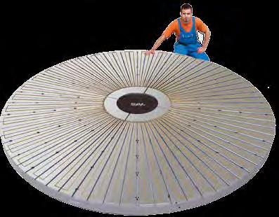

168 CONSULTING DEVELOPMENT MNUFCTURING SLES SERVICE V DESIGN-GENTUR OTTO 2012
MAGNETIC WORKHOLDING. Grinding Pallet Milling EDM Turning Lifting BRC-06-EN
 MAGNETIC WORKHOLDING Grinding Pallet Milling EDM Turning Lifting Permanent Electro Electro-permanent BRC-0-EN Magnetic Workholding Applications Table of contents Grinding EMA ---------------------------------------------------
Guide units. For toolmaking, fixture manufacturing and machine engineering
 Guide units For toolmaking, fixture manufacturing and machine engineering Guide units in compliance with DIN, ISO and STEINEL standards or according to your specifications Guide pillars Guide and pillar
Geared scroll chuck with optimized design
 Geared scroll chucks Geared scroll chuck with optimized design Benefit from proven quality in optimized design. A splash water edge at the upper chuck edge is used as additional protection of the spindle
Live and Dead Centres
 s w i t z e r l a n d Live and Dead Centres 1. Live-Centres 1.1 Main-Line ROTOR Main-Line, the approved top of the range for lathes and grinding machines. Very precise and robust construction. Made for
BEST OF 2014 January December
 Best of 2014 BEST OF 2014 January December 2405 K POWER CHUCK 3274 SELF-CENTRING SCROLL CHUCK 3 JAW 3, 60o serrations, through hole. Interchangeable with Kitagawa type B-200 Cast iron, plain back, front
PROVEN CHUCK WITH SPIRAL RING
 PROVEN CHUCK WITH SPIRAL RING The RÖHM geared scroll chucks have already been in use for decades and have proven themselves a thousand times over. The jaws can be quickly adjusted over the entire clamping
Geared scroll chuck with optimized design
 Geared scroll chucks Geared scroll chuck with optimized design Benefit from proven quality in optimized design. A splash water edge at the upper chuck edge is used as additional protection of the spindle
ZERO-POINT CLAMPING SYSTEM
 simple. gripping. future. ZERO-POINT CLAMPING SYSTEM 22 Quick Point Grid Plates 3 Quick Point Plates 34 Quick Point Round Plates 39 Quick Point Adaptor Plates 4 Quick Point Clamping Studs 43 Quick Point
L Standard Parts for Mould Making
 A Die Sets B Precision Ground Plates and Flat Bars C Lifting and Clamping Devices Shanks, Lifter Studs and Lifting Hooks, Eyebolts Clamping Claws, Screws and Bolts D Guide Elements E Ground Precision Components
BEST OF 2015 January December
 BISON opens its new manufacturing facility improving quality and service 53,000 sq. metre site 33,600 sq. metre of manufacturing State of the art design and manufacturing under one roof BEST OF 2015 January
Shaft Couplings Flange-Couplings Rigid Shaft Couplings Flexible Couplings
 Shaft Couplings Flange-Couplings Rigid Shaft Couplings Flexible Couplings 44 Edition 2013/2014 RINGSPANN Registered Trademark of RINGSPANN GmbH, Bad Homburg 2 Table of Contents Flange-Couplings Page Flange-Couplings
JAWS INDIVIDUALLY ADJUSTABLE
 JAWS INDIVIDUALLY ADJUSTABLE The four jaws can be independently adjusted via the threaded spindle, thereby allowing the safe and secure clamping of irregular, regular, as well as round workpieces. 3072
Steel / Cast iron body Independent chucks
 Independent chucks Steel / Cast iron body Independent chucks Independent 4-jaw chucks - Jaws individually adjustable through threaded adjusting spindle. RÖHM-Independent chucks in steel or cast iron design
CAPTIS. The modular and flexible system for internal and external clamping
 NEW CAPTIS Clamping system The modular and flexible system for internal and external clamping CAPTIS Clamping SYSTEM The new, modularly designed CAPTIS clamping system is very impressive with its high
B Precision Ground Plates and Flat Bars. E Ground Precision Components. G Elastomer-Bars, -Sheets, -Sections
 A Die Sets B Precision Ground Plates and Flat Bars C Lifting and Clamping Devices Shanks, Lifter Studs and Lifting Hooks, Eyebolts Clamping Claws, Screws and Bolts D Guide Elements E Ground Precision Components
Compatibility overview of accessories for drilling machines
 Compatibility overview of accessories for drilling machines Convincing arguments: quality, efficiency and price Direct-SSBF MT 2 3050571 MT 2 3050572 MT 3 3050573 MT 4 3050574 Precision-SSBF 0-8 mm 3050608
Small Tool Instruments and Data Management
 Small Tool Instruments and Data Management Dial Gauge Stands Pages 268 272 Comparator Stands Pages 273 274 Joint Magnetic Stands Concentricity testers Pages 275 280 Angulometers, steel squares Pages 281
WORKHOLDING AUTOMATION SOLUTION MAGNETIC LIFTING
 AUTOMATION SOLUTION MAGNETIC LIFTING EXPERIENCED INNOVATIVE PATHBREAKING SAV-CATALOGU ES MAGNETIC WITH PRECISION AND PERFORMANCE STATIONARY STANDARD AND SPECIAL PRODUCTS COMPETENCE AND QUALITY FIRST-HAND
GTO Precise, universal stationary chuck for collets
 Precise, universal stationary chuck for collets Advantages of the stationary chuck: Rapid and easy mounting Quick change of the standard collets Sensitive adjustment of the clamping force possible Highest
tough. Live Centers Face Drivers 2013/2014
 tough. Live Centers Face Drivers 2013/2014 www.roehm.biz LIVE CENTERS - FACE DRIVERS Revolving tailstock centres Basic 2005 Heavy 2009 Speed 2011 Slim 2012 Control 2014 Flex 2015 Revolving centering tapers
your reliable partner ROBA-stop K.800.V09.EN
 your reliable partner ROBA-stop K.800.V09.EN www..com your reliable partner Your Advantages When Using ROBA-stop ROBA-stop brakes attract customers because of their decided advantages in relation to operational
SAMPLES GAUGES. Tolerances OUR SPECIAL OFFER: PLUG GAUGES WITH REQUIRED FIT OR INDIVIDUAL TOLERANCES ACCORDING TO YOUR SPECIFICATIONS
 SAMPLES GAUGES PLUG GAUGES Tolerances GO side Fit NO GO side OUR SPECIAL OFFER: PLUG GAUGES WITH REQUIRED FIT OR INDIVIDUAL TOLERANCES ACCORDING TO YOUR SPECIFICATIONS BESTSELLER: FEELER GAUGE TAPES IN
Accessories, spare parts and measuring equipment
 Accessories, spare parts and measuring equipment The broad range of accessories, spare parts and measuring equipment represents a useful addition to the range of actual clamping tools and offers spare
Clamping Tools
 Clamping Tools Drill chuck Tapping chuck/ tapping machines Taper bore tools HSK inserts Tool holder for lathes Tool pre-setter 1 1.3 1.8 Reduction sleeves Spindle Sleeves Ejector Drifts Adapter sleeves
Lenze. Drives with worm gearboxes 52.
 6 887 Lenze Drives with worm gearboxes 5. Lenze Drive Systems GmbH, Postfach 0 5, D-76 Hameln, Site: Groß Berkel, Hans-Lenze-Straße, D-855 Aerzen, Phone ++9 (0) 55 8-0, Telefax ++9 (0) 55 8- E-Mail: Lenze@Lenze.de
mechanics RDH-M Indexing Table/Rotary Axis B 210 RDH-S Indexing Table/Rotary Axis B 212 RF 1 Indexing Table B 214 D 1 Indexing Table B 216
 Overview RDH-M Indexing Table/Rotary Axis B 210 RDH-S Indexing Table/Rotary Axis B 212 RF 1 Indexing Table B 214 D 1 Indexing Table B 216 D 2 Indexing Table B 218 MD 1 Midget Rotary Axis B 220 ZR 20 Indexing
ROBATIC ROBA -quick ROBA -takt. Reliable coupling and braking.
 Reliable coupling and braking Equipment Technology Packaging Machinery Conveyors and Materials Handling Equipment Door drives Indexing tables ROBATIC ROBA -quick ROBA -takt www.mayr.de Electromagnetic
Geared scroll chucks with independently adjustable jaws
 Geared scroll chucks with independently adjustable jaws ES This chuck is used for aligning irregularly shaped workpieces. Geared scroll chucks Principle of operation Through a radially arranged drive (1,
JAWS INDIVIDUALLY ADJUSTABLE
 JAWS INIVIUALLY AJUSTAL The four jaws can be independently adjusted via the threaded spindle, thereby allowing the safe and secure clamping of irregular, regular, as well as round workpieces. 3072 INPNNT
Collet chucks KSZ-MB KSZ-NZ KSZ-AZL NEW NEW SMW-AUTOBLOK 147. Группа компаний "Штрай" Москва, ул. Островитянова, 13
 Collet chucks KSZ-MB Collet chuck Power operated collet chucks for bar machining quick collet change Page 148 KSZ-DZ Draw collet chuck for bars KSZ-AZ Draw collet chuck with workstop Page 152 Page 155
QUICK-ACTING JAW CHANGE SYSTEM
 QUICK-ACTING JAW CHANGE SYSTEM The RÖHM key bar chucks with quick-acting jaw change system convince in two ways. On the one hand the jaws can be quickly and easily turned, changed or offset over the entire
Collet Chucks and Collets
 ollet hucks and ollets a complete collection of top quality products for bar and second operation work from the world s number one name in workholding Product Index Short Length ollet hucks... 5 5 & 16
BSW , -493, -494 Mechanical Rotary Cam Switches. User's Guide. Mechanical Rotary Cam Switches BSW BSW BSW
 BSW 819-492, -493, -494 User's Guide Mechanical Rotary Cam Switches BSW 819-492 BSW 819-493 BSW 819-494 The CE Marking is your guarantee that our products meet the requirements of EC Directive 89/336/EC
BEST OF A selection of our most popular products. To view the complete range visit
 BEST OF 2016 January December A selection of our most popular products To view the complete range visit /products Welcome to BISON Empowered By Precision BISON opens new manufacturing facility making it
Magnetic Effects of Electric Current
 CHAPTER13 Magnetic Effects of Electric Current Multiple Choice Questions 1. Choose the incorrect statement from the following regarding magnetic lines of field (a) The direction of magnetic field at a
Selection Tool. on the Internet at in the section MÄDLER -Tools. Other sizes and designs on request. Connecting Shafts Page 766
 Couplings Overview Friction Clutches Friction Clutches Type B Axial Arrangement Friction Clutches Type C Transversal Flexibility Sliding Hubs with Torsionally-Flexible Coupling Multi-Disk Friction Clutches
General information on radial seals
 170 General information on radial seals Radial seals is the common name for shaft seals, which seal against a rotating shaft using an elastic and resilient lip of rubber or PTFE. The lip in turn is either
USE-USU. Steel independent chucks. Steel independent chucks USE-USU
 USE-USU The jaws can be centered approximately by adjusting them to the concentric grooves, accurate centering requires the use of a dial indicator. Independent 4-jaw chuck Technical features: - jaws individually
ZG-ZS. Geared scroll chucks. Geared scroll chucks ZG-ZS
 The spiral ring chuck - a proven and universal suitable clamping system - finds it s application wherever a high clamping force, high runout accuracy and very high repeatability are required. For use on
Small Tool Instruments and Data Management
 Small Tool Instruments and Data Management Digital Micrometers Pages 28 34 Analogue Micrometers Pages 35 42 Special Version Micrometers Pages 43 63 External screw type micrometers accessories Pages 65
Rotary inlets for pressurised oil, compressed air
 Rotary inlets for pressurised oil, compressed air Product data sheets Rotary inlets for pressure oil, single channel 0086-010-size-160 9.03.00 Rotary inlets for pressure oil, two- channel 0088-226/326-size-010040
THe BeST OF THe BeST OF NeW. NeW. NeW. empowered. by precision. empowered. empowered precision. A selection of our most popular products
 THe BeST OF 2017 A selection of our most popular products THe BeST OF 2017 AA selection selection of of our our most most popular popular products products To view the complete complete range range visit
ROTARY TABLES SERIE TC TECHNOLOGY THAT INSPIRES
 ROTARY TABLES SERIE TC TECHNOLOGY THAT INSPIRES TC FIXED-STATION ROTARY INDEXING TABLES TC ROTARY INDEXING TABLE TC ROTARY INDEXING TABLE: RELIABILITY FOR A LIFETIME EXTENDED WARRANTY Using our rotary
3QLC, 3QLK, 3QLC-KS, 3QLK-KS 2QLC-LS, 3QLC-LS, 3QLC-AG, QLC-KT Power Chucks
 3QLC, 3QLK, 3QLC-KS, 3QLK-KS 2QLC-LS, 3QLC-LS, 3QLC-AG, QLC-KT Power Chucks This catalogue describes the key components of a power chucking system featuring the following FORKARDT power chucks: QLC, QLK,
METAL DRILLING. Metal Drilling ENGINEERED FOR CONTROLLED PRECISION AND SPEED 118 SPLIT POINT 118 STANDARD POINT 135 SPLIT POINT TURBOMAX JET POINT
 128 METAL DRILLING ENGINEERED FOR CONTROLLED PRECISION AND SPEED The IRWIN line of metal drill bits offers of a solution for every professional application. Each metal drill bit is made of high speed steel
Spindles and converters
 High Speed Spindles F A C T S A B O U T Spindles and converters SPINTEC spindles are designed for clients with high demands on accuracy and reliability of service. The spindles are manufactured with the
POWER CHUCKS KTN / KTG / KS
 POWER CHUCKS KTN / KTG / KS This catalogue features details of the range of FORKRT KT and KS power chucks. Should you require further information beyond the data contained in this catalogue, please refer
Steering column and sensor
 Steering column and sensor Type LAB Series 1 x Nominal voltage 12 to 48 volt Output signal digital, analog and direction (option) HE 11874 / 09.2017 2 LAB HE 11874 / 09.2017 Page Content 4 4 5 6 7 7 8
Chuck size
 URO-T / URO A Exterior form incl. splash water edge URO-T Technical features RÖHM URO-T Manual chucks: 20% higher clamping forces Chuck body stiffer (guarantees precision at higher loads) Surface of chuck
Wedge clamps
 Wedge clamps Wedge clamps for dies with tapered clamping edge Without position monitoring up to 160 C* 2.24000 With position monitoring lateral fastening up to 100 C** 2.24001 With position monitoring
Sensor-Bearing Units Steer-By-Wire Modules Mast Height Control units Other sensorized units
 Mechatronics Sensor-Bearing Units... 957 Steer-By-Wire Modules... 967 Mast Height Control units... 969 Other sensorized units... 971 955 Sensor-Bearing Units SKF Sensor-Bearing Units... 958 SKF Explorer
enduring. Drill Chucks NC-Tooling 2013/2014
 enduring. Drill Chucks NC-Tooling 2013/2014 www.roehm.biz DRILL CHUCKS - NC-TOOLING Keyless drill chucks EXTRA 1004 EXTRA-RV 1005 SUPRA 1006 SUPRA-SK 1008 SUPRA-SK E 1008 SPIRO - SPIRO-SK 1009 Key-type
Axial-radial cylindrical roller bearings
 Axial-radial cylindrical roller bearings Designs and variants.............. 320 Bearing data..................... 321 (Boundary dimensions, tolerances) Product table 5.1 Axial-radial cylindrical roller
PROVEN CHUCK WITH SPIRAL RING
 PROVEN CHUCK WITH SPIRAL RING The RÖHM geared scroll chucks have already been in use for decades and have proven themselves a thousand times over. The jaws can be quickly adjusted over the entire clamping
LATHE CHUCKS INDEPENDENT CHUCKS
 LATHE CHUCKS INDEPENDENT CHUCKS 2017 NEW RÖHM eshop First B2B eshop of the clamping technology industry Buy RÖHM products online 24/7 Order as a guest customer without registration Intuitive search and
HSS ground for steel to 900 N/mm 2, aluminium alloys, brass, bronze. Use For producing screw through-holes DIN EN 20273,
 Drilling Tools Step drills 184 Step drills T - Countersink angle - With straight shank - Cone envelope grind - Web-thinned chisel edge and surface treatment For producing threaded core holes and countersinks
Split plummer block housings SED 30, 31, 32 and 39 series
 Split plummer block housings SED 30, 31, 32 and 39 series Bearing types Spherical roller bearings Bearing dimension series 30, 31, 32 and 39 Shaft diameter range 430 to 900 mm Typical shaft-bearing combinations
TURNING AND MILLING IN ONE SET-UP
 TURNING AND MILLING IN ONE SET-UP Application example - face driver CoE in combination with a revolving live centre. Turning and milling workpieces in one set-up. Video CoE 2036 CONSTANT FACE DRIVERS The
ZGU-ZSU heavy design. Geared scroll chucks. Geared scroll chucks. ZGU-ZSU heavy
 ZGU-ZSU heavy design Type 303 3-jaw-chuck cylindrical centre mount The spiral ring chuck - a proven and universal suitable clamping system - finds it s application wherever a high clamping force, high
Performance requires quality.
 131 - With straight shank and square - Left-hand spiral 7-8 - First cut 1/4 of the cutting length (l 2 ) - Accuracy Hand Reamers DIN 26. Not suitable for blind holes. d 1 l 2 l 1 d 2 131 2, 25 5 1,6 21
Air vane motors for special applications
 Screwdriving technology Automation Air motors Air tools Air vane motors for special applications drilling motors 80-600 W milling motor 400 W grinding motors 150-1000 W robust and precise bearing high
ER Collets Nuts Disks
 Collets Nuts Disks 1 Collets - Features Benefits 2 Concentricity T.I.R. 3 Assembly Instructions 4 8 8-UP 8-MB 5 11 11-UP 11-MB 11-ND 6 16 16-UP 16-MB 7 20 20-UP 8 25 25-UP 9 32 32-UP 10 40 40-UP 12 50
MAGNETIC WORKHOLDING for GRINDING. Electro-Permanent magnetic chucks
 MGNETI WORKHOLDING for GRINDING Electro-Permanent magnetic chucks ELETRO-PERMNENT MGNETI HUKS RILLON MGNETIS, inventor of Electro-Permanent technology, provides a range of powerful, reliable and waterproof
Shaft-Hub-Connections
 Stand: 14.01.2010 Shaft-Hub-Connections Shrink Discs Cone Clamping Elements Star Discs 36 Edition 2012/2013 RINGSPANN Eingetragenes Warenzeichen der RINGSPANN GmbH, Bad Homburg Table of Contents Introduction
Standard Programme Clamping Technology. The tool specialists for the trade.
 Standard Programme Clamping Technology The tool specialists for the trade. Direction Leipzig 4 Direction Dresden Direction Erfurt Chemnitz 72 95 The tool specialists for the trade. WTE Präzisionstechnik
Online data sheet DFS60B-S4CA08192 DFS60 INCREMENTAL ENCODERS
 Online data sheet DFS60B-S4C08192 DFS60 B C D E F Illustration may differ Detailed technical data Performance Ordering information Type Part no. DFS60B-S4C08192 1038099 Other models and accessories www.sick.com/dfs60
Flexible Couplings 44
 Flexible Couplings 44 RINGSPANN Registered Trademark of RINGSPANN GmbH, Bad Homburg MTY (81) 83 54 10 18 Why RINGSPANN Flexible Couplings? No connection of shafts without clutches It is a well-known fact
FSG-2040ADII/2060ADII 2440ADII/2460ADII/2480ADII COLUMN TYPE HIGH PRECISION 3-AXIS AUTOMATIC SURFACE GRINDER
 FSG-2040ADII/2060ADII 2440ADII/2460ADII/2480ADII COLUMN TYPE HIGH PRECISION 3-AXIS AUTOMATIC SURFACE GRINDER 1 CONTROL PANEL F S G - 2 0 / 2 4 COLUMN TYPE HIGH PRECISION 3-AX 1. Control power supply switches
GENERAL SPECIFICATION
 GENERAL SPECIFICATION Description FSG-2040ADII FSG-2060ADII FSG-2440ADII FSG-2460ADII FSG-2480DII Table Size 19 5/8 x393/8 (500x1000mm) 19 5/8 x59 (500x1500mm) 24 x39 3/8 (610x1000mm) 24 x59" (610x1500mm)
mechanics RDH-M Indexing Table / Rotary Axis C 158 RDH-S Indexing Table / Rotary Axis C 160 RDH-XS Indexing Table / Rotary Axis C 162
 Overview RDH-M Indexing Table / Rotary Axis C 158 RDH-S Indexing Table / Rotary Axis C 160 RDH-XS Indexing Table / Rotary Axis C 162 DSH-S Rotary Swivelling Unit C 164 RF 1 Indexing Table C 166 D 1 Rotary
Multi-Purpose Milling Machine
 Multi-Purpose Milling Machine MF most widely used milling machine type world-wide! MF 1 speed change through v-belt change-over Multi-Purpose Milling Machine for workshops, single part production, design,
Online data sheet DFS60B-S4EL00800 DFS60 INCREMENTAL ENCODERS
 Online data sheet DFS60B-S4EL00800 DFS60 B C D E F Illustration may differ Detailed technical data Performance Ordering information Type Part no. DFS60B-S4EL00800 1053600 Other models and accessories www.sick.com/dfs60
Swiss Automatic Tooling
 Swiss Automatic Tooling 1 Collets - Features Benefits 2 Concentricity T.I.R. 3 Assembly Instructions 4 8 8-UP 8-MB 5 11 11-UP 11-MB 11-ND 6 16 16-UP 16-MB 7 20 20-UP 8 25 25-UP 9 Metallic Sealed Collets
SIT-LOCK self locking elements
 self locking elements Advantages of on the shaft-hub connection compared with traditional systems Easy assembly and disassembly Both actions take place by locking and unlocking the clamping screws with
This is trial version
 Z-Standards Contents (Alphabetical order, terms partly according to DIN 16750) A All dimensions shown in this catalogue are specified in mm, given tolerances refer to an ambient temperature of 20 C Prod.-No.
Operating Instructions. Parallel shaft cam gear
 Operating Instructions Parallel shaft cam gear Type : Serial No. : C O N T E N T S 1. General 1.1 Validity 1.2 Safety instructions 1.3 Shipment 1.4 Transport Regulations 1.5 Weights of gear types 2. Instructions
2006 MINI Cooper S GENINFO Starting - Overview - MINI
 MINI STARTING SYSTEM * PLEASE READ THIS FIRST * 2002-07 GENINFO Starting - Overview - MINI For information on starter removal and installation, see the following articles. For Cooper, see STARTER WITH
Shaft Couplings Tru-Line Flange-Couplings Rigid Shaft Couplings Flexible Couplings
 Shaft Couplings Tru-Line Flange-Couplings Rigid Shaft Couplings Flexible Couplings Edition 2015/2016 RINGSPANN Registered Trademark of RINGSPANN GmbH, Bad Homburg Table of Contents Tru-Line Flange-Couplings
Leading magnetic solutions. Eclipse Magnetics Ltd HANDLING / WORKHOLDING DIVISION
 Handling & Systems Leading magnetic solutions Eclipse Magnetics Ltd HANDLING / WORKHOLDING DIVISION PICK CLAMP HOLD MANIPULATE Contents All of the following products are based around permanent magnets
FUNCTION OF A BEARING
 Bearing FUNCTION OF A BEARING The main function of a rotating shaft is to transmit power from one end of the line to the other. It needs a good support to ensure stability and frictionless rotation. The
Transport with Magnets
 Wagner Magnete GmbH & Co. KG Obere Straße 15 D-87751 Heimertingen Phone: +49 (0) 8335 980-0 Fax: +49 (0) 8335 980-270 www.wagner-magnete.de e-mail: info@wagner-magnete.de Technology Full of Attraction
VAV terminal units. Type TVM. For dual duct systems PD TVM 1
 X X testregistrierung VAV terminal units Type Variant -S Rectangular connection on the room end For dual duct systems VAV dual duct terminal units for dual duct systems with variable volume flows in buildings
Installation and Operational Instructions for ROBATIC -clutch Type and Type Sizes 3 9
 Please read the Operational Instructions carefully and follow them accordingly! Ignoring these Instructions may lead to malfunctions or to clutch failure, resulting in damage to other parts. Contents:
Online data sheet DFS60B-S4PC10000 DFS60 INCREMENTAL ENCODERS
 Online data sheet DFS60-S4PC10000 DFS60 DFS60-S4PC10000 DFS60 C D E F H I J K L M N O P Q R S T Ordering information Type Part no. DFS60-S4PC10000 1036721 Other models and accessories www.sick.com/dfs60
LIMITED ANGLE TORQUE MOTORS
 LIMITED ANGLE TORQUE MOTORS Limited Angle Torque Motors H2W Technologies Limited Angle Torque Motors are ideal for compact, limited angular excursion (
Universal. CNC Turning machine TNA500 TNA600
 Universal CNC Turning machine TNA500 TNA600 TRAUB TNA this name is highly regarded throughout the world for machining large chuck, shaft or bar parts. With their precision and efficiency, short setup time
ROTARY WORKHOLDING. From standard to complete solutions
 ROTRY WORKHOLDING From standard to complete solutions CONTENT PICTOGRM PGE CHPTER V The company 03-10 tandard chucks and accessories 11-40 pecial chucks 41-60 tandard mandrels 61-66 pecial mandrels 67-74
Standard Knockout Punches 10. Punch Kits for Hydraulic Drivers 11. Draw Stud Selection Guide 13, 14, 18. Special Shape Punches
 8 Punching Tools, Hole Saws, Step Bits Page Punching Tools Standard Knockout Punches 10 Slug Buster Knockout Punches 10 Slug Splitter Knockout Punches 10, 12 Punch Kits for Hydraulic Drivers 11 Draw Stud
BRUSH-HOLDER PLUG SETS CATALOGUE
 BRUSH-HOLDER PLUG SETS CATALOGUE Introduction Table of Contents 1 Introduction... 2 2 System Description... 3 2.1 Subsystems and Components... 3 2.2 Function... 4 2.3 Brush Clamping... 4 2.4 Electrical
Online data sheet. DBS60E-S4EP05000 DBS60 Core INCREMENTAL ENCODERS
 Online data sheet DBS60ES4EP05000 DBS60 Core DBS60ES4EP05000 DBS60 Core A B C D E F Ordering information Type Part no. DBS60ES4EP05000 1071649 Other models and accessories www.sick.com/dbs60_core Illustration
BoWex FLE-PA. BoWex FLE-PAC. KTR-N Sheet: Edition: EN 1 of BoWex FLE-PA / FLE-PAC Operating/Assembly instructions
 1 of 17 is a torsionally rigid flange coupling. It is able to compensate for shaft misalignment, for example caused by manufacturing inaccuracies, thermal expansion, etc. BoWex FLE-PA BoWex FLE-PAC Drawn:
FSG-2A818/3A818 HIGH PRECISION SURFACE GRINDER
 FSG-2A818/3A818 HIGH PRECISION SURFACE GRINDER FSG-2A8 1 FEATURES HIGH PRECISION SU FSG-2A818.3A818 These grinders have been specially developed and improved in recent years by us to continuously offer
Magnetic and Hydraulic-Magnetic Circuit Breaker 8340-G V
 Description Single and two pole magnetic circuit breakers with trip-free mechanism and push/pull on/off manual actuation. A choice of fast magnetic only or hydraulically delayed switching characteristics
Three-phase roller table motors with squirrel-cage rotor for the application at the frequency converters Series A21O, A20O, ARB, ARC.
 Three-phase roller table motors with squirrel-cage rotor for the application at the frequency converters Series A21O, A20O, ARB, ARC Product summary VEM motors GmbH Introduction Roller table motors are
Locking Line. Electromagnetic Locking Systems
 Locking Line Electromagnetic Locking Systems Kendrion - Industrial Magnetic Systems We develop solutions! Kendrion develops, manufactures and markets highquality electromagnetic and mechatronic systems
RIGIFLEX -N RADEX -N. Steel laminae coupling. Steel laminae coupling. You will find continuously updated data in our online catalogue at
 117 Table of contents 117 Coupling selection steel laminae coupling 119 Description of coupling 121 General information 122 Types and applications 123 Technical data 124 Standard types 126 Special types
DEUTROFLUX UWE Universal Stationary Magnetic Particle Crack Detectors
 DEUTROFLUX UWE Universal Stationary Magnetic Particle Crack Detectors Reliable testing for cracks in all directions Optionally with Memory II: Operation via Siemens Touch Panel with parameter memory (e.
POWER CHUCKS CYLINDERS / STEADY RESTS
 POWER CHUCKS CYLINDERS / STEADY RESTS 2015/2016 NEW RÖHM eshop First B2B eshop of the clamping technology industry Buy RÖHM products online 24/7 Order as a guest customer without registration Intuitive
10.3 Flanged Connections acc. to EN 1092
 10.3 Flanged Connections acc. to EN 1092 EN 1092 is split into two sections: - EN 1092-1 edition 09-2008 for steel flanges - EN 1092-2 edition 06-1997 for cast iron flanges EN 1092 contains dimensions
FSG-1224ADII/1632ADII /1640ADII AUTOMATIC PRECISION SURFACE GRINDING MACHINE
 FSG-1224ADII/1632ADII /1640ADII AUTOMATIC PRECISION SURFACE GRINDING MACHINE F S G - 1 2 / 1 6 A D 1 FEATURES AUTOMATIC PRECISION SURFAC FSG-1224ADII 1632ADII 1640ADII AUTOMATIC PRECISION SURFACE GRINDING