LATHE CHUCKS INDEPENDENT CHUCKS
|
|
|
- Ruth O’Neal’
- 6 years ago
- Views:
Transcription


1 LATHE CHUCKS INDEPENDENT CHUCKS 2017


2 NEW RÖHM eshop First B2B eshop of the clamping technology industry Buy RÖHM products online 24/7 Order as a guest customer without registration Intuitive search and filter function The first B2B eshop of the clamping technology industry provides you with the comprehensive range of RÖHM catalogue products. In addition the customer receives extensive product information. Possibility to order in the eshop as an existing customer as well as a guest customer by credit card or bank transfer. RÖHM GmbH info@roehm.biz Hotline
3 2

4 Table of contents LATHE CHUCKS I INDEPENDENT CHUCKS Key bar chucks with quick jaw change system DURO-T 3009 DURO-TA 3020 DURO-TA XT 3027 Geared scroll chucks ZS - ZSU 3036 Orange Line 3046 ZS Hi-Tru 3054 ES 3069 KRF 3074 BAV 3078 Adapter plates 3079 Independent chucks USE - USU 3084 Clamping force measurement device F-senso chuck 3061 Errors and corrections are reserved!

 ISO 702-3 (DIN 55027) DIN 6350 BVV")


5 Lathe chucks and Independent chucks Operation guide E ORANGE LIN TYPE DURO-T DURO-TA DURO-TA XT Operatione guide Key bar chucks with quick jaw change system Chucking capacities mm Cylindrical centre mount DIN 6350 ISO (DIN 55027) Mount mm Cylindrical centre mount DIN 6350 ZS - ZSU Orange Line Geared scroll chucks mm Individual mm Cylindrical centre mount DIN 6350 ISO (DIN 55029) ISO (DIN 55027) DIN 6350 BVV (mounting from front) mm Cylindrical centre mount DIN 6350 Through-hole Number of jaws Types of jaws Workpiece Machining Rotating/ Stationary Clamping Clamping force Speed max. Precision Feature Page quick jaw change system 3009 yes grinding chuck with quick jaw change system 3020 weight reduced with splash water groove and control edge jaw chuck pipe flange 4-jaw chuck bar asymmetrical workpiece disc 3002 with splash water groove and control edge

 Operation guide Through-hole Number of jaws Types of jaws Workpiece Machining Rotating/")


6 Lathe chucks and Independent chucks Operation guide TYPE ZS Hi-Tru ES KRF USE - USU Chucking capacities Mount Geared scroll chucks Independent chucks mm mm mm mm Cylindrical centre mount DIN 6350 Cylindrical centre mount DIN 6351 Cylindrical centre mount DIN 6350 Cylindrical centre mount ISO (DIN 55029) ISO (DIN 55027) Operation guide Through-hole Number of jaws Types of jaws Workpiece Machining Rotating/ Stationary Clamping Clamping force Speed max. Precision Feature radial precision adjustment, with special seal for grinding machines independently adjustable jaws keyless clamping, specially for measuring and grinding machines independently adjustable jaws Page inside jaw + outside jaw reversible jaw rotating machining independently adjustable jaws base jaw lenght machining stationary machining base and top jaw side machining selfcentering 3003
 Camlock fixing (ISO 702-2) Spindle nose size A B C D E F Technical data Typ A1-A2, B1-B2 A1: Tapped holes in flange (outer bolt circle) and inner bolt circle. From taper size 4 with driver.")


7 Technical data Machine spindle noses for DIN and ASA B 5.9 Machine spindle noses (not included in the scope of delivery) ISO (DIN and ASA B 5.9 D1) Camlock fixing (ISO 702-2) Spindle nose size A B C D E F Technical data Typ A1-A2, B1-B2 A1: Tapped holes in flange (outer bolt circle) and inner bolt circle. From taper size 4 with driver. 3 92,1 53,985 11,1 31,8 3x15,1 70, ,5 63,525 11,1 33,3 3x16,7 82, ,575 12,7 38,1 6x19,8 104, ,390 14,3 44,5 6x23 133, ,4 139,735 15,9 50,8 6x26,2 171, ,5 196,885 17,5 60,3 6x , ,9 6x35,7 330, , ,5 6x42,1 463,6 Latest edition of relevant DIN standard applies in each case Spindle nose size Holes on outer bolt circle (F1) Outer bolt circle Holes on inner bolt circle (F2) Inner bolt circle A B C -0,025 D E1 F1 E2 F2 A1 (corresponds ISO 702-1) 5 133,4 82,575 14,288 22,2 11x 7/ UNC 104,8 8x 7/ UNC 61, ,1 106,390 15,875 25,4 11x 1/ 2-13 UNC 133,4 8x 1/ 2-13 UNC 82, ,5 139,735 17,462 28,6 11x 5/ 8-11 UNC 171,4 8x 5/ 8-11 UNC 111, ,4 196,885 19,05 34,9 11x 3/ 4-10 UNC 235 8x 3/ 4-10 UNC 165, ,800 20,638 41,3 12x 7/ 8-9 UNC 330,2 11x 7/ 8-9 UNC 247, ,800 22,225 47,6 12x 1-8 UNC 463,6 12x 1-8 UNC 368,3 * A2: Tapped holes in flange (outer bolt circle) without inner bolt circle. Spindle nose size Holes on outer bolt circle (F1) Outer bolt circle A B C D E1 F1 A2 (corresponds ISO 702-1) 3 92,1 53,985 11,1 15,9 3x 7/ UNC 70, ,525 11, x 7/ UNC 82, ,4 82,575 12,7 22,2 11x 7/ UNC 104, ,1 106,390 14,3 25,4 11x 1/ 2-13 UNC 133, ,5 139,735 15,9 28,6 11x 5/ 8-11 UNC 171, ,4 196,885 17,5 34,9 11x 3/ UNC , ,3 12x 7/ 8-9 UNC 330, ,800 20,6 47,6 12x 1-8 UNC 463,6 B1: Through-holes in flange (outer bolt circle), tapped holes in inner bolt circle - from taper size 4 with driver. B2: Through-holes in flange (outer bolt circle) without inner bolt circle. Spindle nose size Outer bolt circle Holes on inner bolt circle (F2) Inner bolt circle A B C -0,025 D F1 G F1 E2 F2 B ,4 82,575 14,288 22,2 11x11,9 104,8 8x 7/ UNC 61, ,1 106,390 15,875 25,4 11x13,5 133,4 8x 1/ 2-13 UNC 82, ,5 139,735 17,462 28,6 11x16,7 171,4 8x 5/ 8-11 UNC 111, ,4 196,885 19,05 34,9 11x20, x 3/ 4-10 UNC 165, ,800 20,638 41,3 12x23,4 330,2 11x 7/ 8-9 UNC 247, ,800 22,225 47,6 12x26,6 463,6 12x 1-8 UNC 368,3 * * From taper size 4 with driver Spindle nose size Outer bolt circle A B C D G F1 B2 3 92,1 53,985 11,1 15,9 3x11,9 70, ,525 11, x11,9 82, ,4 82,575 12,7 22,2 11x11,9 104, ,1 106,390 14,3 25,4 11x13,5 133, ,5 139,735 15,9 28,6 11x16,7 171, ,4 196,885 17,5 34,9 11x20, , ,3 12x23,4 330, ,800 20,6 47,6 12x26,6 463,6 3004

 E2 F2 3 102 53,985 11 16 3xM10 3x10,5 75 - - 4 112 63,525 11 20 3xM10 3x10,5 85 - - 5 135 82,575 13 22 7xM10 4x10,5 104,8 8xM10 61,9 6 170 106,390 14 25 7xM12 4x13")
 Form B: Tapped holes and through-holes in flange (outer bolt circle) and")
 E2 F2 3 92 53,983 11-16 3xM10 70,6 - - 4 108 63,521 11-20 11xM10 82,6 - - 5 133 82,573 13 14,288 22 11xM10 104,8 8xM10 61,9 6 165 106,385 14 15,875 25")
 without inner bolt circle.")
 With bayonet ring fixing (ISO 702/III) * Spindle nose size A B C D Number of holes x E 3 102 53,985 11 16 3x21 75 4 112 63,525 11 20 3x21 85 5 135 82,575")
8 Techincal data Machine spindle noses for DIN and ASA B 5.9 Machine spindle noses (not included in the scope of delivery) DIN 800, with thread Mean tol. A Bg5 Minimum C D E F M , M M M M M M M76x M105x DIN From taper size 4 with driver Spindle nose size Holes on outer bolt circle (F1) Outer bolt circle Holes on inner boltcircle Inner bolt circle Technical data A B C D E1 G F1 (F2) E2 F , xM10 3x10, , xM10 3x10, , xM10 4x10,5 104,8 8xM10 61, , xM12 4x13 133,4 8xM12 82, , xM16 4x17 171,4 8xM16 111, , xM20 6x xM20 165, , xM24 6x25 330,2 11xM24 247, , xM24 6x25 463,6 11xM24 368,3 Form A: Tapped holes and through-holes in flange (without inner bolt circle) Form B: Tapped holes and through-holes in flange (outer bolt circle) and tapped holes in inner bolt circle ISO (DIN 55026) From taper size 4 with driver Spindle nose size Holes on outer bolt circle Outer bolt circle Holes on inner bolt circle Inner bolt circle A B C C 1 D E1 F1 (F2) E2 F , xM10 70, , xM10 82, , , xM10 104,8 8xM10 61, , , xM12 133,4 8xM12 82, , , xM16 171,4 8xM16 111, , , xM xM20 165, , , xM24 330,2 11xM24 247, , , xM24 463,6 11xM24 368,3 Form A: Tapped holes in flange (outer bolt circle) without inner bolt circle. Form B: Tapped holes in flange (outer bolt circle) and in inner bolt circle. ISO (DIN und 55022) With bayonet ring fixing (ISO 702/III) * Spindle nose size A B C D Number of holes x E , x , x , x21 104, , x23 133, , x29 171, , x , x43 330, , x43 463,6 F * From taper size 4 with driver 3005


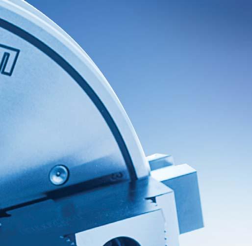
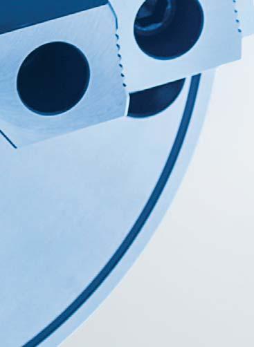
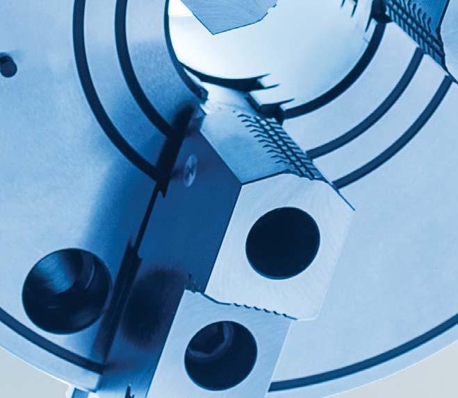
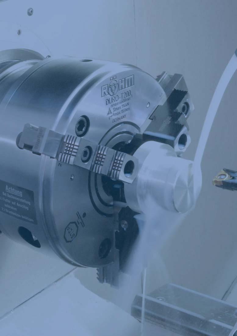
9 QUICK JAW CHANGE SYSTEM The RÖHM key bar chucks with quick jaw change system convince in two ways. On the one hand the jaws can be quickly and easily turned, changed or offset over the entire clamping range within a few seconds. On the other the key bar chucks convince with maximum clamping forces and maximum accurancy thanks to direct force transfer via the key bar system. Large, straight surfaces transmitting the force from the key bar to the jaw teeth guarantee long life and produce a very high clamping force combined with an accurancy which is twice high as required by DIN The high clamping force is achieved without much physical effort by manually turning the key. Video DURO-T 3006

10 KEY BAR CHUCK WITH QUICK JAW CHANGE SYSTEM The RÖHM key bar chucks with quick jaw change system are used successfully in areas where extremely high clamping forces, high concentricity and reliable long-term repeatability are required. Thanks to the quick jaw change system, the jaws can be quickly and easily turned, changed or offset over the entire clamping range within a few seconds. ADVANTAGES AT A GLANCE Key bar chuck with quick jaw Maximum clamping forces thanks to direct force transfer via the key bar system Maximum concentricity and axial run-out tolerance High user-friendliness thanks to quick jaw change system Chuck body completely surfacehardened for maximum precision, even under extreme load Jaws in chuck ground out for concentricity Precise and high force transfer by means of key bar system Quick jaw change system with pressure bolt for turning, exchanging and offsetting the jaws within a few seconds 3007
, the force is transferred via a key bar (2) having an internal thread. The key bar moves the drive ring via a slide (3).")

11 DURO-T Key bar chucks with quick jaw change system The DURO-T key bar chuck guarantees maximum precision, maximum clamping force and is completely balanced ex works Principle of operation Thanks to the tangentially arranged threaded spindle (1), the force is transferred via a key bar (2) having an internal thread. The key bar moves the drive ring via a slide (3). Two other slides in the drive ring (4) transfer the forces to the other two key bars. The key bars having an inclined profile engage in the base jaws (5), thereby guaranteeing exact, centric clamping. The jaws can be quickly and easily turned, changed or offset over the entire clamping range within a few seconds. To do this, the key bars must be disengaged by turning the key to the left; the indicator pin (6) will project here. In this position, the jaws are secured against being hurled out in the event the machine spindle is started up unintentionally. Therefore, the gate valve (7) of each jaw must be unlocked via the corresponding pressure bolt (8) on the outer diameter of the chuck. Large, straight-line force transfer surfaces between the key bar and jaw toothing yield a very high clamping force over a long service life and precision which is twice as high as prescribed by DIN The high clamping force is achieved without exerting any special amount of force by manually turning the key. Lubrication To maintain the clamping force, key bar chucks must be lubricated regularly. You will find corresponding information in the operating instructions which are enclosed with every chuck. For easy maintenance, DURO-T chucks are equipped with three additional grease nipples on the front side

12 Key bar chucks with quick jaw change system DURO-T - with quick jaw change system APPLICATION Optimized for turning applications, which require extremely high clamping forces, maximum concentricity, as well as reliable long-term repeatability. In combination with a base plate, stationary use on milling machines, dividing units and machining centers. TYPE Key bar chuck with quick jaw change system. Guaranteed maximum jaw precision as far as these are only used on the same chuck, and base and top jaws are kept screwed on for recurring work. CUSTOMER BENEFITS Maximum clamping force thanks to key bar system Concentricity and axial run-out tolerance twice as exact as required in DIN precision class 1 Very high jaw change repeatability Balanced and jaws in chuck ground out for concentricity TECHNICAL FEATURES - With jaw safeguard - Chuck body completely surface-hardened - Visual marking for quick jaw adjustment - External shape incl. splash-water edge - Fastening options for strongly stressed sliding surfaces - Incl. safety key - High corrosion protection Key bar chucks DURO-T A08 Cylindrical centre mount Size Inch Throughhole mm With one-piece reversible jaws With base jaws With base jaws and reversible top jaws D mm F mm Speed max. min -1 Max. Torque Nm , / / / At size 630 chuck body without convex outer contours Further sizes and mountings available on request Max. total clamping force kn A08 ISO (DIN 55026), DIN 55021, ASA B 5.9, mounting from front Size Mount short taper Throughhole mm With one-piece reversible jaws With base jaws With base jaws and reversible top jaws D mm F mm Speed max. min -1 Max. Torque Nm , , , , , , , , ) , ) By conserving the precision At size 630 chuck body without convex outer contours Further sizes and mountings available on request Max. total clamping force kn 3009
13 Key bar chucks with quick jaw change system DURO-T - with quick jaw change system A08 ISO (DIN 55027), with studs and locknuts Key bar chucks DURO-T Size Mount short taper Throughhole mm With one-piece reversible jaws With base jaws With base jaws and reversible top jaws D mm F mm Speed max. min -1 Max. Torque Nm , , , , , , , , , , ) ) , ) By conserving the precision At size 630 chuck body without convex outer contours Further mountings available on request. Max. total clamping force kn A08 ISO (DIN 55029), stud for Camlock Size Mount short taper Throughhole mm With one-piece reversible jaws With base jaws With base jaws and reversible top jaws D mm F mm Speed max. min -1 Max. Torque Nm , , ,5 82, , , ,5 82, , , , ,5 82, , , , , , , , , , , ) ) , ) By conserving the precision At size 630 chuck body without convex outer contours Max. total clamping force kn 3010


14 Jaws DURO-T Key bar chucks with quick jaw change system A28 One-piece jaw EB, 3-jaw set, diagonally toothing, hardened Item no. Chuck Size Number of jaws Contents of delivery Jaw length mm Jaw height mm Jaw width mm set set 77, set 94, set set /500 3 set Additionally or later applied, hardened stepped jaws must be ground out in the chuck. For jaws which are applied later, send in the chuck. A28 Unstepped jaw BL, 3-jaw set, diagonally toothing, unstepped, soft, material 16MnCr5 Item no. Chuck Size Number of jaws Contents of delivery Jaw length mm Jaw height mm Jaw width mm set set 84, set 98, set 118, set 136, /500 3 set 173, Jaws DURO-T A28 Reversible top jaw UB, 3-jaw set, hardened tongue and groove for external and internal clamping, material 16 MnCr5 Item no. Chuck Size Number of jaws Contents of delivery Jaw length mm Jaw height mm Jaw width mm set 61,5 32,5 20, set 70, , set , set , /500 3 set , set Additionally or later applied hardened jaws must be ground out in the chuck. For jaws which are applied later, send in the chuck. A28 Unstepped top jaw AB, 3-jaw set, standard design, soft, material 16 MnCr5 Item no. Chuck Size Number of jaws Contents of delivery Jaw length mm Jaw height mm Jaw width mm set 55 25,5 20, set 85 36,5 20, set set , set , /500 3 set , set A28 Unstepped top jaw AB, 3-jaw set, extendend design, soft, material 16MnCr5 Item no. Chuck Size Number of jaws Contents of delivery Jaw length mm Jaw height mm Jaw width mm set 85 42,5 24, set , set , set ,5 3011
15 Jaws DURO-T Key bar chucks with quick jaw change system A28 Base jaw GB, 3-jaw set, diagonally toothing, with mounting bolts Item no. Chuck Size Number of jaws Contents of delivery Jaw length mm Jaw width mm set set set set set /500 3 set set Jaws DURO-T C 21 Reversible claw-type top jaws, standard design, tongue and groove, large clamping range, 1 piece, hardened Item no. Chuck Size Jaw length mm Jaw height mm Jaw width mm , / C 21 Reversible claw-type top jaws, standard design, tongue and groove, small clamping range, 1 piece, hardened Item no. Chuck Size Jaw length mm Jaw height mm Jaw width mm , / C 21 Reversible claw-type top jaws, standard design, tongue and groove, medium clamping range, 1 piece, hardened Item no. Chuck Size Jaw length mm Jaw height mm Jaw width mm , / C 21 Reversible claw-type top jaws, large design, tongue and groove, small clamping range, 1 piece, hardened Item no. Chuck Size Jaw length mm Jaw height mm Jaw width mm /
16 Jaws DURO-T Key bar chucks with quick jaw change system C 21 Reversible claw-type top jaws, large design, tongue and groove, large clamping range, 1 piece, hardened Item no. Chuck Size Jaw length mm Jaw height mm Jaw width mm / C 21 Reversible claw-type top jaws, large design, tongue and groove, medium clamping range, 1 piece, hardened Item no. Chuck Size Jaw length mm Jaw height mm Jaw width mm / Jaws DURO-T C 21 Draw-down jaws, for interchangeable clamping inserts, diagonally toothing, 1 piece, without clamping inserts Item no. Chuck Size Jaw length mm Jaw height mm Jaw width mm ,4 43, ,4 47, ,7 58, ,4 63, / ,6 73,4 45 C 21 Draw-down jaws, additional clamping range, for interchangeable clamping inserts, diagonally toothing, 1 piece, without clamping inserts Item no. Chuck Size Jaw length mm Jaw height mm Jaw width mm ,4 43, ,4 47, ,7 58, ,4 63, ,6 73, ,6 73,


17 Jaws DURO-T Key bar chucks with quick jaw change system C 15 Interchangeable clamping inserts, 1 piece, with claws Item no. Chuck Size / / /500/630 Jaws DURO-T C 15 Interchangeable clamping inserts, 1 piece, with serrated toothing Item no. Chuck Size / / /500 C 15 Interchangeable clamping inserts, 1 piece, with heat treatable surface Item no. Chuck Size / / /500 C15 Jaw mounting bolt, piece Item no. Size Thread Contents of delivery M6x10 piece /200 M8x22 piece M12x30 piece M12x35 piece /500 M16x40 piece M20x50 piece 3014

18 Key bar chucks with quick jaw change system Accessories DURO-T A08 Base plate with fixing slots Complete with mounting screws and fixed T-slot nuts. Other sizes available on request. A08 Key Item no. Size Item no. Size Square L mm A08 Safety key Item no. Size Square L mm A08 Torque wrench Only for stationary used chucks Item no. Torque Nm Length mm Output Working accuracy ,7=1/2 3% ,7=1/2 3% Accessories DURO-T Corresponding with DIN 1550 for rotating chucks A08 Chip guard set A08 Safety adapter Item no. Size Contents of delivery Item no. Size Square Length mm Mount set set set set set set / / / / / / / /2 A08 Special grease F80 for lathe chucks for lubrication and conservation of chucking power Item no. Design Contents Cartridge 0,5 kg Tin 1 kg 3015
19 Technical Data DURO-T Technical Data DURO-T Technische Daten DURO-T A1 A E N G C O H L Q F J M K D α P B Chuck size A Outer diameter A Jaw movement B 4,8 6,2 6,8 8 10,2 12,5 12,5 14 Bore C Bore cab be enlarged C max D 46, E H F G H 3xM8 3xM10 3xM12 3xM16 3xM20 3xM24 3xM24 3xM24 J K 22,5 31, ,7 57,5 72 L 32, ,5 66, ,5 196 M SW8 SW10 SW12 SW14 SW17 SW19 SW19 SW24 N O P 8, Min. thickness of flange Q Moment of inertia GD2 1) kgm 2 0,01 0,03 0,10 0,29 0,87 2,37 5,78 17,04 21 o o 18 o 19 o 17 o 20 o 42 o 69 o 30 approx. kg kg 4,0 9,3 18,6 34, ) The moment of inertia was measured with base jaws but without top jaws or back plate The bore could be enlarged (measure C, at surcharge) Enlarged bore max. Max. permissible speed The maximum permissible speed has been fixed so that 1/3 of the gripping force is still available as residual gripping force if the maximum grippping is applied and the chuck is fitted with its heaviest jaws. The jaws may not project beyond the outside diameter of the chuck. The chuck must be in perfect condition. The specification DIN 6386 Part 1 shall be observed. Chuck size Max. speed min Gripping force The gripping force is the sum total of all jaw forces acting radially on the stationary workpiece. The specified gripping forces are standard values. They apply to chucks in a perfect condition which have been lubricated with RÖHM grease F79 and F80. Chuck size Torque applied on key 1) Nm Total gripping force 1) kn 8, Torque applied on key Nm Max. total gripping force kn ) Maintaining the accuracy At this torque the clamping jaws have been ground at the factory; for testing the chuck must be clamped with this torque Chuck capacities of jaw steps Chuck size External chucking A A A Jaw position A J Internal chucking J J
20 Jaw dimensions DURO-T Jaw dimensions DURO-T Reversible one-piece jaw EB, hardened and ground, jaw steps not ground Block jaw BL, unstepped, soft, thread and jaw guides hardened and ground Chuck size A 50 77,7 94, B C D 10,7 20, ,5 40,2 50,5 E 16 18,9 19,5 40, F G 29 37, H J 19 22, K L ,5 19,5 30 Jaw approx. kg 0,400 0,500 0,635 1,135 1,835 3,665 Reversible top jaw UB, completely hardened, cross tenon ground, jaw steps not ground Unstepped soft top jaw AB, for turning out special chucking diameters Dimensions for extendend design Base jaws GB, hardened and ground Chuck size A 53 84,4 98,4 118,7 136,6 173,6 B C Jaw approx. kg 0,435 0,500 0,900 1,535 2,400 5 Chuck size A 61,5 70, B 20,4 24,4 34,4 35,7 50,4 68 C D E 3 3,5 3,5 3,5 4,5 4,5 F 32, G 22,5 25, ,5 41,4 59 H J K L 26,5 28, M , N 17, O P 23, Q R T 1) 38, ,6 80,6 114 Jaw approx. kg 0,200 0,335 0,800 1,135 2,535 6,350 1) Dimension marked on base jaw Chuck size A B 20,7 20,3 24, ,3 30,4 50,5 34,3 50,5 50,5 68 C 31, D E 3, ,5 3,5 3,5 3,5 3,5 3,5 4,5 4,5 F 25,5 36,5 42, G H J 7, K P 24 27,5 33, Q 6, R S M6 M8x1 M8x1 M8x1 M8x1 M12x1,5 M12x1,5 M12x1,5 M12x1,5 M16x1,5 M20 T 1) 32 42,5 48, ,6 71,6 81,6 114 U 18 19,5 25, Jaw approx. kg 0,200 0,435 0,600 0,735 1,400 1,500 3,700 2,265 4,800 4,500 13,350 1) Dimension marked on base jaw Chuck size A B C D E - 5 5,5 5,5 6,5 7,5 9 F G 2,8 2, H 3, ,6 8,6 12 J 7, K M6 M8x1 M8x1 M12x1,5 M12x1,5 M16x1,5 M20 L M Jaw approx. kg 0,200 0,265 0,365 0,700 1,065 2,350 5,665 Jaw dimesions DURO-T 3017
21 Chucking capacities DURO-T Chucking capacities DURO-T Reversible claw-type top jaws KB, standard design Reversible claw-type top jaw, large clamping range Chuck size Item no Capacities external Ø min. - max. 142,5-187, Capacities internal Ø min. - max. 22,5-67, Interfering contour Reversible claw-type top jaw, small clamping range Spannbereiche Chucking capacities DURO-T Chuck size Item no Capacities external Ø min. - max. 37,5-82, Capacities internal Ø min. - max Interfering contour Reversible claw-type top jaw, medium clamping range Chuck size Item no Capacities external Ø min. - max Capacities internal Ø min. - max Interfering contour
22 Notes Notes 3019
23 Key bar chucks with quick jaw change system DURO-TA - sealed design APPLICATION Specially for grinding machines. Optimized for extremely high clamping forces, maximum concentricity, as well as reliable long-term repeatability. TYPE Key bar chuck with quick jaw change system. Guaranteed maximum jaw precision as far as these are only used on the same chuck, and base and top jaws are kept screwed on for recurring work. CUSTOMER BENEFITS Maximum clamping force thanks to key bar system With cover for protection against dust on the face Very high jaw change repeatability Key bar chucks DURO-TA TECHNICAL FEATURES - With jaw safeguard - Chuck body completely surface-hardened - Visual marking for quick jaw adjustment - External shape incl. splash-water edge - Fastening options for strongly stressed sliding surfaces - Incl. safety key - High corrosion protection A08 Cylindrical centre mount Size Inch With base jaws With inside and outside jaw D mm Speed max. min -1 Max. Torque Nm Max. total clamping force kn / Further sizes and mountings available on request 3020


24 Jaws DURO-TA A28 Outside jaw DB, set, inward stepped jaw, hardened Key bar chucks with quick jaw change system Item no. Chuck Size Contents of delivery Jaw width mm set set set 26 Additionally or later applied, hardened stepped jaws must be ground out in the chuck. For jaws which are applied later, send in the chuck. A28 Inside jaw BB, set, outward stepped jaw, hardened Item no. Chuck Size Contents of delivery Jaw width mm set set set 26 Additionally or later applied, hardened stepped jaws must be ground out in the chuck. For jaws which are applied later, send in the chuck. Jaws DURO-TA A28 Unstepped top jaw AB, 3-jaw set, soft, material 16MnCr5 Item no. Chuck Size Contents of delivery Jaw length mm Jaw height mm Jaw width mm set 90 36,5 20, set set ,4 A28 Base jaw GB, 3-jaw set, hardened, with mounting bolts Item no. Chuck Size Contents of delivery Jaw length mm Jaw height mm Jaw width mm set set set C15 Jaw mounting bolt, piece Item no. Size Thread Contents of delivery /200 M8x22 piece M12x30 piece 3021
25 Key bar chucks with quick jaw change system Accessories DURO-TA A08 Base plate with fixing slots Complete with mounting screws and fixed T-slot nuts. Other sizes available on request. A08 Key Item no. Size Item no. Size Square L mm Only for stationary used chucks A08 Safety key A08 Torque wrench Accessories DURO-TA Item no. Size Square L mm Corresponding with DIN 1550 for rotating chucks Item no. Torque Nm Length mm Output Working accuracy ,7=1/2 3% ,7=1/2 3% A08 Chip guard set A08 Safety adapter Item no. Size Contents of delivery Item no. Size Square Length mm Mount set set set / / /2 A08 Special grease F80 for lathe chucks For lubrication and conservation of chucking power Item no. Design Contents Cartridge 0,5 kg Tin 1 kg 3022
26 Technical data DURO-TA Technical data DURO-TA A1 A E N G C O H L Q F J M K D α P B Chuck size Outer diameter A Jaw movement B 6,2 6,8 8 Bore C Bore can be enlarged C max D E H F G H 3xM10 3xM12 3xM16 J K 31, L 42 53,5 66,5 M SW10 SW12 SW14 N O P Min. thickness of flange Q Moment of inertia 1) kgm 2 0,03 0,10 0, Weight approx kg 9, ) The moment of inertia was measured with base jaws but without top jaws or back plate The bore could be enlarged (measure C, at surcharge) Enlarged bore max. Technical data DURO-TA Max. permissible speed The maximum permissible speed has been fixed so that 1/3 of the gripping force is still available as residual gripping force if the maximum grippping is applied and the chuck is fitted with its heaviest jaws. The jaws may not project beyond the outside diameter of the chuck. The chuck must be in perfect condition. The specification DIN 6386 Part 1 shall be observed. Chuck size Max. speed min Gripping force The gripping force is the sum total of all jaw forces acting radially on the stationary workpiece. The specified gripping forces are standard values. They apply to chucks in a perfect condition which have been lubricated with RÖHM grease F79 and F80. Chuck size Torque applied on key in 1) Nm Total gripping force 1) kn Torque applied on key in Nm Max. total gripping force kn ) Maintaining the accuracy Chucking capacities of jaw steps Chuck size External chucking A A A Jaw A position. J Internal chucking J J Chuck dimensions DURO-TA - Main dimensions (other dimensions on the table on the top) Chuck size Outer diameter A External chucking with BB-jaws External chucking with DB-jaws Internal chucking with BB jaws Central bor for coolant B C D
27 Jaw dimensions and chucking capacity DURO-TA Jaw dimensions and chucking capacity DURO-TA Outward stepped jaw BB Chuck size A B C max ,5 C min D E Jaw approx. kg 0,465 0,643 1,065 Jaw dimensions and chucking capacity Inward stepped jaw DB Unstepped soft top jaw AB Chuck size A B C max ,5 C min D E Jaw approx. kg 0,435 0,600 1,065 Chuck size A B 20, C D E 3 3,5 3,5 F 36, G H J K P 27, Q R S M8x1 M8x1 M12x1,5 U 19, Jaw approx. kg 0,435 0,800 1,500 Base jaw GB Chuck size A B C D E 5 5,5 5,5 F G 2,5 7 7 H J K M8x1 M8x1 M12x1,5 L M max ,5 M min Jaw approx. kg 0,335 0,365 0,
28 Notes Notes 3025


29 DURO-TA XT Key bar chucks with quick jaw change system Equipped with extended and easy to assemble guideways the new lightweight DURO-TA XT is convincing with a flexible clamping area for machining large and small workpieces. Weight-reducing by up to 75 % makes maximum utilisation of the machine s potential possible. DURO-TA XT Key bar chucks Guideways The new DURO-TA XT has an innovative concept for guideways that guarantees flexible and weight-reducing use. In contrast to other large chucks, the DURO-TA XT is up to 75 % lighter and that way makes maximum utilisation of the machine s potential possible and clamping of higher workpiece weights. Through the extended and easy to assemble guideways, the clamping area can be set flexibly and hence converted quickly to large and small workpieces. Through the direct mount on the base body, the guideways guarantee extremely high rigidity, stability and protection against penetration by dirt and dust. Principle of operation Thanks to the tangentially arranged threaded spindle, the force is transferred via a key bar having an internal thread. The key bar moves the drive ring via a slide. Two other slides in the drive ring transfer the forces to the other two key bars. The key bars having an inclined profile engage in the base jaws, thereby guaranteeing exact, centric clamping. Proven DURO-TA base body with dirt cover Flexible clamping area for quick conversion to large and small workpieces Guideways mounted directly and connected to the chuck for the greatest stability and accuracy Reduced overall height of up to 78 % for better accessibility of the workpieces and minimum interfering contours 3026
30 Key bar chucks with quick jaw change system DURO-TA XT - with removable guideways APPLICATION On turning and milling machines. TYPE Key bar chuck (DURO-TA) with removable guideways. CUSTOMER BENEFITS Weight reduction by up to 75% Maximum flexibility and faster retrofitting Innovative design with minimum interference contour and maximum stability TECHNICAL FEATURES - Weight reduction by up to 75% allows maximum utilization of the machine potential and the clamping of heavier workpieces - Flexible clamping range thanks to elongated guideways for faster conversion between large and small workpieces - Easy dismounting of the guideways for clamping smaller workpieces - Minimum interference contour and better workpiece accessibility thanks to compact design and a reduced design height by up to 78% - High stability thanks to direct support of the permanently screwed guideways Key bar chucks DURO-TA XT full base plate max. lightweight base plate A08 DURO-TA XT key bar chuck with complete base plate Item no. Size Clamping range external with extended jaws * Clamping range external with standard jaws ** Interfering contour mm Jaw travel mm Weight kg Speed max. Max. Torque Nm Max. total clamping force min -1 kn Weight reduction compared to a standard chuck % (250) / (315) / , (500) , Customized adaptations of the base plate for further weight reduction on the machine table on request * By dismounting of the stripping cap and use of standard reversible jaws ** By shortening of the base jaws. Please consider shorter clamping ranges Further sizes and mountings available on request 3027
 3 set 114 70 26 094003 1000 (315) 3 set 130 79 32 094043 1250 (500) 3 set 167 93 45")

31 Key bar chucks with quick jaw change system Jaws DURO-TA XT A28 One-piece jaw EB, 3-jaw set, diagonally toothing, hardened Item no. Chuck Size Number of jaws Contents of delivery Jaw length mm Jaw height mm Jaw width mm (250) 3 set (315) 3 set (500) 3 set Additionally or later applied, hardened stepped jaws must be ground out in the chuck. For jaws which are applied later, send in the chuck. Jaws only usable in basic chuck. Jaws DURO-TA XT A28 Unstepped jaw BL, 3-jaw set diagonally toothing, unstepped, soft, material 16MnCr5 Item no. Chuck Size Number of jaws Contents of delivery Jaw length mm Jaw height mm Jaw width mm (250) 3 set 118, (315) 3 set 136, (500) 3 set 173, Jaws only usable in basic chuck. A28 Reversible top jaw UB, 3-jaw set, hardened tongue and groove for external and internal clamping, material 16 MnCr5 Item no. Chuck Size Number of jaws Contents of delivery Jaw length mm Jaw height mm Jaw width mm (250) 3 set , (315) 3 set , (500) 3 set ,4 Additionally or later applied hardened jaws must be ground out in the chuck. For jaws which are applied later, send in the chuck. Jaws only usable in basic chuck. A28 Base jaw GB, 3-jaw set, diagonally toothing, with mounting bolts Item no. Chuck Size Number of jaws Contents of delivery Jaw length mm Jaw width mm (250) 3 set (315) 3 set (500) 3 set Jaws only usable in basic chuck. C 21 Draw-down jaws, for interchangeable clamping inserts, diagonally toothing, 1 piece, without clamping inserts Item no. Chuck Size Jaw length mm Jaw height mm Jaw width mm (250) 118,7 58, (315) 136,4 63, (500) 173,6 73,4 45 Jaws only usable in basic chuck. C 21 Draw-down jaws, additional clamping range, for interchangeable clamping inserts, diagonally toothing, 1 piece, without clamping inserts Item no. Chuck Size Jaw length mm Jaw height mm Jaw width mm (250) 118,7 58, (315) 136,4 63, (500) 173,6 73,4 45 Jaws only usable in basic chuck. 3028
/1000 (315) 141055 1250 (500) Jaws only usable in basic chuck. C 15 Interchangeable clamping inserts, 1 piece, with serrated toothing Item no.")
32 Key bar chucks with quick jaw change system Jaws DURO-TA XT C 15 Interchangeable clamping inserts, 1 piece, with claws Item no. Chuck Size (250)/1000 (315) (500) Jaws only usable in basic chuck. C 15 Interchangeable clamping inserts, 1 piece, with serrated toothing Item no. Chuck Size (250)/1000 (315) (500) Jaws only usable in basic chuck. Jaws DURO-TA XT C 15 Interchangeable clamping inserts, 1 piece, with heat treatable surface Item no. Chuck Size (250)/1000 (315) (500) Jaws only usable in basic chuck. A28 Reversible top jaw UB, 3-jaw set, hardened tongue and groove for external and internal clamping, material 16 MnCr5 Item no. Number of jaws Contents of delivery Jaw length mm Jaw width mm set 92 34, set , set ,4 Additionally or later applied hardened jaws must be ground out in the chuck. For jaws which are applied later, send in the chuck. A28 Unstepped top jaw AB, 3-jaw set, standard design, soft, material 16 MnCr5 Item no. Chuck Size Number of jaws Contents of delivery Jaw length mm Jaw height mm Jaw width mm (250) 3 set , (315) 3 set , (500) 3 set ,5 C 21 Reversible claw-type top jaws, standard design, tongue and groove, large clamping range, 1 piece, hardened Item no. Chuck Size Jaw length mm Jaw height mm Jaw width mm (500)
 72 55 34 137115 1000 (315) 86 62 34 137121 1250 (500) 100 62 50 C 21 Reversible claw-type top jaws, standard design, tongue and")
33 Key bar chucks with quick jaw change system Jaws DURO-TA XT C 21 Reversible claw-type top jaws, standard design, tongue and groove, medium clamping range, 1 piece, hardened Item no. Chuck Size Jaw length mm Jaw height mm Jaw width mm (250) (315) (500) C 21 Reversible claw-type top jaws, standard design, tongue and groove, small clamping range, 1 piece, hardened Jaws DURO-TA XT Item no. Chuck Size Jaw length mm Jaw height mm Jaw width mm (250) (315) (500) C 21 Reversible claw-type top jaws, large design, tongue and groove, small clamping range, 1 piece, hardened Item no. Chuck Size Jaw length mm Jaw height mm Jaw width mm (250) (315) C 21 Reversible claw-type top jaws, large design, tongue and groove, medium clamping range, 1 piece, hardened Item no. Chuck Size Jaw length mm Jaw height mm Jaw width mm (250) (315) C 21 Reversible claw-type top jaws, large design, tongue and groove, large clamping range, 1 piece, hardened Item no. Chuck Size Jaw length mm Jaw height mm Jaw width mm (250) (315) Accessories DURO-TA XT C15 Special grease F80 for lathe chucks For lubrication and conservation of chucking power C15 Torque wrench Item no. Design Contents Cartridge 0,5 kg Tin 1 kg Item no. Torque Nm Length mm Output Working accuracy ,7=1/2 3% ,7=1/2 3% A08 Safety adapter Item no. Size Square Length mm Mount (250) / (315) / (500) /2 3030
34 Technical data DURO-TA XT Technical data DURO-TA XT Chuck size A Outer diameter Chuck A Outer diameter Base plate A Jaw movement B 8 10,2 12,5 Bore 1) C D D E H F G H K 79,5 98,0 97,5 L 66, ,5 M SW14 SW17 SW19 N R R S Moment of inertia GD2 2) kgm 2 10,52 37,92 98,70 Moment of inertia GD2 2) 3) kgm 2 5,66 18,10 48,93 4,6 o 4,6 o 4,5 o approx. kg kg approx. kg 3) kg full base plate Technical data DURO-TA XT 1) With dirt cover 2) The moment of inertia was measured with base jaws but without top jaws 3) With max. lightweight base plate max. lightweight base plate Max. permissible speed The maximum permissible speed has been fixed so that 1/3 of the gripping force is still available as residual gripping force if the maximum grippping is applied and the chuck is fitted with its heaviest jaws. The jaws may not project beyond the outside diameter of the chuck. The chuck must be in perfect condition. The specification DIN 6386 Part 1 shall be observed. Chuck size Max. speed min Gripping force The gripping force is the sum total of all jaw forces acting radially on the stationary workpiece. The specified gripping forces are standard values. They apply to chucks in a perfect condition which have been lubricated with RÖHM grease F79 and F80. Chuck size Torque applied on key 1) Nm Total gripping force 1) kn Torque applied on key Nm Max. total gripping force kn ) Maintaining the accuracy At this torque the clamping jaws have been ground at the factory; for testing the chuck must be clamped with this torque Chuck capacities of jaw steps Chuck size External chucking A A Jaw position A Internal chucking J J max. interfering contour 808/** /** ** By shortening of the base jaws. Please consider shorter clamping ranges. 3031
35 Jaw dimensions DURO-TA XT Jaw dimensions DURO-TA XT Jaw dimensions DURO-TA XT Reversible top jaw UB, completely hardened, cross tenon ground, jaw steps not ground Jaws only usable in basic chuck. Unstepped soft top jaw AB, for turning out special chucking diameters Dimensions for extendend design Chuck size A B 34,4 35,7 50,4 C D E 3,5 3,5 4,5 F G 30 35,5 41,4 H J K L M 40, N O P Q R T 1) 57 63,6 80,6 Jaw approx. kg 0,800 1,135 2,535 1) Dimension marked on base jaw Chuck size A B 30,4 50,5 34,3 50,5 50,5 C D E 3,5 3,5 3,5 3,5 4,5 F G H J K P Q R S M12x1,5 M12x1,5 M12x1,5 M12x1,5 M16x1,5 T 1) ,6 71,6 81,6 U Jaw approx. kg 1,500 3,700 2,265 4,800 4,500 1) Dimension marked on base jaw Reversible one-piece jaw EB, hardened and ground, jaw steps not ground Jaws only usable in basic chuck. Blockbacken BL, ungestuft, ungehärtet, Verzahnung und Führung gehärtet und geschliffen. Jaws only usable in basic chuck. Chuck size A B C D 41,5 40,2 50,5 E 40, F G H J K L 19,5 19,5 30 Jaw approx. kg 1,135 1,835 3,665 Chuck size A 118,7 136,6 173,6 B C Jaw approx. kg 1,535 2,400 5 Base jaws GB, hardened and ground Jaws only usable in basic chuck Chuck size A B C D E 5,5 6,5 7,5 F G H 7 7,6 8,6 J K M12x1,5 M12x1,5 M16x1,5 L M Jaw approx. kg 0,700 1,065 2,350
36 Notes Notes 3033

37 PROVEN CHUCK WITH SPIRAL RING The RÖHM geared scroll chucks have already been in use for decades and have proven themselves a thousand times over. The jaws can be quickly adjusted over the entire clamping range by means of the spiral ring. Using the radially arranged drive, the force is transferred to the hardened spiral ring via a bevel gearing and further conducted to the clamping jaws via the spiral. 3034

38 GEARED SCROLL CHUCKS The RÖHM geared scroll chucks have proven themselves a thousand times over and have already been used successfully on lathes, rotary tables and dividing attachments for decades. The jaws can be adjusted over the entire clamping range in order to be able to very quickly clamp workpieces with a wide clamping diameter range without offsetting the jaws. ADVANTAGE AT A GLANCE Geared scroll chucks Quick jaw adjustment over the entire clamping range Proven chuck with optimal price/performance ratio Protection of the machine spindle by means of splash-water edge Spiral ring for precise force transfer and quick jaw adjustment over the entire clamping range Radially arranged drive for defined torque introduction using a torque wrench Protection of the machine spindle from cooling lubricant by means of splash-water edge Control edge for quick and easy adjustment on the machine 3035
39 Geared scroll chucks in steel design ZS - ZSU - centric clamping APPLICATION Proven geared scroll chuck for use in areas requiring high clamping forces, high concentricity as well as reliable long-term repeatability. For universal use on lathes, rotary tables, dividing units, etc. TYPE Geared scroll chucks in steel design. 3-jaw and 4-jaw version. Geared scroll chucks ZS - ZSU CUSTOMER BENEFITS High clamping force Special flat design for minimum interfering contours The jaws can be adjusted over the entire clamping range by turning the key. This allows workpieces with different clamping diameters to be quickly clamped Jaws in chuck ground out for concentricity TECHNICAL FEATURES - With one-piece jaws or with base and top jaws - Steel body and spiral ring die-forged - Series-balanced and hardened ZS = centric clamping, steel ZSU = centric clamping, steel, reversible top jaws DIN 6350, cylindrical centre mount, form A Size ZA Through-hole mm 3-jaw chuck with inside and outside jaw 4-jaw chuck with inside and outside jaw 3-jaw chuck with base and reversible top jaw 4-jaw chuck with base and reversible top jaw Speed max. Torque Nm Total clamping min -1 force kn Further sizes and mountings available on request Geared scroll chucks in 6-jaw design available on request Mounting from front, DIN 6350, cylindrical centre mount Size ZA Through-hole mm 3-jaw chuck with inside and outside jaw 4-jaw chuck with inside and outside jaw Speed max. min -1 Torque Nm Total clamping force kn Further sizes and mountings available on request 3036

 101196 100757 101199 4600 110 47 200 5 42 100168 1) 101446 100172 101452 4000 140 55 200 6 55 100173 1) 101454 100177 101460 4000 140 55")
 101939 101386 101945 2300 180 69 350 6 103 114643 127557 127848 127850 1900 210 74 350 8 76 117319 1) 117320 127847 127849 1900 210 74 400 8 136 102226 102353 102232 102359 1800")
40 Geared scroll chucks in steel design ZS - ZSU - centric clamping ISO (DIN 55026), DIN 55021, ASA B 5.9, A1/A2 metr.; mounting from front Size Mount short taper Through-hole mm 3-jaw chuck with inside and outside jaw 4-jaw chuck with inside and outside jaw 3-jaw chuck with base and reversible top jaw 4-jaw chuck with base and reversible top jaw Speed max. Torque Nm Total clamping min -1 force kn ) ) ) ) ) ) ) ) ) ) Mounting from front in the inner bolt circle Geared scroll chucks ZS - ZSU ISO (DIN 55029), ASA B 5.9, type D, with studs for Camlock Size Mount short taper Through-hole mm 3-jaw chuck with inside and outside jaw 4-jaw chuck with inside and outside jaw 3-jaw chuck with base and reversible top jaw 4-jaw chuck with base and reversible top jaw Speed max. Torque Nm Total clamping min -1 force kn , Further sizes and mountings available on request ISO (DIN 55027), with studs and locknuts, optional DIN with set screw and nut Size Mount short taper Through-hole mm 3-jaw chuck with inside and outside jaw 4-jaw chuck with inside and outside jaw 3-jaw chuck with base and reversible top jaw 4-jaw chuck with base and reversible top jaw Speed max. Torque Nm Total clamping min -1 force kn , Further sizes and mountings available on request 3037


41 Jaws ZS - ZSU Geared scroll chucks in steel design Inside jaw BB, DIN 6350, outward stepped jaw, hardened Chuck Size 3-jaw set 4-jaw set Jaw length mm Jaw height mm Jaw width mm , , , , , ,5 34 Additionally or later applied, hardened stepped jaws must be ground out in the chuck. For jaws which are applied later, send in the chuck. Jaws ZS - ZSU Outside jaw DB, DIN 6350, inward stepped jaw, hardened Chuck Size 3-jaw set 4-jaw set Jaw length mm Jaw height mm Jaw width mm , , , , , , / , / Additionally or later applied, hardened stepped jaws must be ground out in the chuck. For jaws which are applied later, send in the chuck. Unstepped jaw BL, DIN 6350, unstepped, soft, material 16MnCr5 Chuck Size 3-jaw set 4-jaw set Jaw length mm Jaw height mm Jaw width mm , , , , , , / , /
42 Jaws ZS - ZSU Base jaw GB, DIN 6350, with fixing screw Geared scroll chucks in steel design Chuck Size 3-jaw set 4-jaw set Jaw length mm Jaw width mm / Reversible top jaws UB, DIN 6350, hardened tongue and groove for external and internal clamping, material 16 MnCr5 Chuck Size 3-jaw set 4-jaw set Jaw length mm Jaw height mm Jaw width mm Jaws ZS - ZSU , , ,7 41, ,5 42, ,3 52, ,5 57, / , / , / Additionally or later applied, hardened stepped jaws must be ground out in the chuck. For jaws which are applied later, send in the chuck. Unstepped top jaw AB, DIN 6350, soft, material 16MnCr5 Chuck Size 3-jaw set 4-jaw set Jaw length mm Jaw height mm Jaw width mm , , , , , ,5 350/ ,5 500/ , /

43 Jaws ZS - ZSU Geared scroll chucks in steel design Unstepped jaw BL, special length, soft, material 16MnCr5, DIN 6350 Chuck Size 3-jaw set 4-jaw set A1 mm X1 max. A mm J mm X max. mm Jaws ZS - ZSU , / / , / / / Unstepped jaw BL, special height, soft, material 16MnCr5, DIN 6350 Chuck Size 3-jaw set 4-jaw set C1 mm J1 mm C mm J mm , , / / , , / / , , /

44 Jaws ZS - ZSU Geared scroll chucks in steel design Top jaw AB, special length, soft, material 16MnCr5, DIN 6350 Chuck Size 3-jaw set 4-jaw set A1 mm X1 max. F mm A mm X max. mm , , / , / , , , / , / , , / , / , Jaws ZS - ZSU Top jaw AB, special height, soft, material 16MnCr5, DIN 6350 Chuck Size 3-jaw set 4-jaw set C1 mm C mm F mm , ,5 350/ ,5 500/ , , ,5 350/ ,5 500/ , ,5 350/ ,5 500/ ,5 Top jaw AB, special width and height, soft, material 16MnCr5, DIN 6350 Chuck Size 3-jaw set 4-jaw set B1 mm C1 mm B mm C mm / / /
45 Jaws ZS - ZSU C15 Mounting bolt for top jaws, bolt 1 Geared scroll chucks in steel design Item no. Size Thread Contents of delivery M6x20 piece M8x25 piece /200 M8x30 piece M12x40 piece M12x45 piece /400 M16x50 piece /630 M20x80 piece Jaws ZS - ZSU C15 Mounting bolt for top jaws, bolt 2 Item no. Size Thread Contents of delivery M6x16 piece /160/200 M8x20 piece M12x25 piece M12x30 piece /400 M16x35 piece /630 M20x40 piece 3042

46 Geared scroll chucks in steel design Accessories ZS - ZSU Base plates for lathe chucks with cylindrical centre mount, DIN 6350 Item no. Size Thread Unfinished adapter plates for cylindrical mount The unfinished back plate must be machined and fitted on both machine and chuck side Item no. Size Inch A mm B mm C mm D mm E mm xM xM xM xM16 Chip guard, piece Item no. Size Contents of delivery ¼ ½ ¼ ½ Special grease F80 for lathe chucks For lubrication and conservation of chucking power Item no. Design Contents Accessories ZS - ZSU /85 piece /110 piece piece /160 piece piece piece /350/400 piece /630 piece Cartridge 0,5 kg Tin 1 kg Scroll Driving pinion Item no. Size Item no. Size Square / Pinion holder screw Standard key Item no. Size Item no. Size Square Hexagon Length mm /125/ / / / / / / / /

 Item no. Size Square Inch Torque wrench Item no.")
47 Geared scroll chucks in steel design Accessories ZS - ZSU Safety key with ejector Item no. Size Square Length mm Elongated safety key with ejector Item no. Size Square Length mm / / / / / / / / Accessories ZS - ZSU / Safety adapter with ejector For actuating the chuck with torque (defined torque introduction) Item no. Size Square Inch Torque wrench Item no. Torque Nm Length mm Output Working accuracy /85 6 3/ ,7=1/2 3% / / ,7=1/2 3% / / / / / / / / / / /630/700/ / / /4 C15 Mounting screws For cylindrical centre rim Item no. Size Thread Contents of delivery C15 Mounting screws For lathe chucks with direct short-taper, for front mounting Item no. Size Thread Contents of delivery Chuck Size Taper size M6x20 piece M8x30 piece M10x35 piece M12x40 piece M16x50 piece M16x60 piece M10x55 piece M10x65 piece M12x65 piece M10x90 piece M12x70 piece M16x70 piece M12x100 piece M16x85 piece /230 M12x130 piece M16x110 piece M20x95 piece M20x130 piece M20x145 piece M24x125 piece Set screw with nut, DIN Item no. Thread For taper Quantity Stud for Camlock ISO (DIN 55029) and cylindrical studs Item no. Thread For taper Quantity M10x M10x M12x M16x M20x M24x M10x M10x M12x M16x1, M20x1, M22x1, M24x1, M27x
48 Geared scroll chucks in steel design Accessories ZS - ZSU Stud and locknut ISO (DIN 55027) Stud for Camlock ASA B 5.9 (DIN 55029) and cylindrical studs Item no. Thread Contents of delivery For taper Quantity Item no. Thread For taper Quantity M10x34 piece M10x39 piece M10x43 piece M12x50 piece M16x60 piece M20x75 piece M24x90 piece M24x100 piece /16-20x /16-20x ½-20x /8-18x ¾-16x55, /8-14x x ½-12x Accessories ZS - ZSU 3045

49 Geared scroll chucks in cast iron design Orange Line - centric clamping ORANGE LINE APPLICATION Proven geared scroll chuck made of special cast iron for use in areas requiring high clamping forces, high concentricity as well as reliable long-term repeatability. For universal use on lathes, rotary tables, dividing units, etc. TYPE Geared scroll chucks in cast iron design. Special flat design with direct mounting. 3-jaw and 4-jaw version. Geared scroll chucks - Orange Line CUSTOMER BENEFITS Optimal price/performance ratio Special flat design for minimum interfering contours The jaws can be adjusted over the entire clamping range by turning the key. This allows workpieces with different clamping diameters to be quickly clamped Jaws in chuck ground out for concentricity TECHNICAL FEATURES - With one set each of one-piece outward- and inward stepped jaws - Vibration-damping body made of special cast iron - Spiral ring die-forged as well as balanced and hardened DIN 6350, cylindrical centre mount, form A Size ZA Through-hole mm 3-jaw chuck with inside and outside jaw 4-jaw chuck with inside and outside jaw Speed max. min -1 Torque Nm Total clamping force kn Mounting from front, DIN 6350, cylindrical centre mount Size ZA Through-hole mm 3-jaw chuck with inside and outside jaw 4-jaw chuck with inside and outside jaw Speed max. min -1 Torque Nm Total clamping force kn
50 Geared scroll chucks in cast iron design Jaws Orange Line Inside jaw BB, DIN 6350, outward stepped jaw, hardened Chuck Size 3-jaw set 4-jaw set Jaw length mm Jaw height mm Jaw width mm , , , , , ,5 34 Additionally or later applied, hardened stepped jaws must be ground out in the chuck. For jaws which are applied later, send in the chuck. Outside jaw DB, DIN 6350, inward stepped jaw, hardened Chuck Size 3-jaw set 4-jaw set Jaw length mm Jaw height mm Jaw width mm , , , , , ,5 34 Additionally or later applied, hardened stepped jaws must be ground out in the chuck. For jaws which are applied later, send in the chuck. Jaws Orange Line Unstepped jaw BL, DIN 6350, unstepped, soft, material 16MnCr5 Chuck Size 3-jaw set 4-jaw set Jaw length mm Jaw height mm Jaw width mm , , , , , ,5 34 Base jaw GB, DIN 6350, with fixing screw Chuck Size 3-jaw set 4-jaw set Jaw length mm Jaw width mm Reversible top jaws UB, DIN 6350, hardened tongue and groove for external and internal clamping, material 16 MnCr5 Chuck Size 3-jaw set 4-jaw set Jaw length mm Jaw height mm Jaw width mm , , ,7 41, ,5 42, ,3 52, ,5 57,5 42 Additionally or later applied, hardened stepped jaws must be ground out in the chuck. For jaws which are applied later, send in the chuck. 3047
51 Geared scroll chucks in cast iron design Jaws Orange Line Unstepped top jaw AB, DIN 6350 soft, material 16MnCr5 Chuck Size 3-jaw set 4-jaw set Jaw length mm Jaw height mm Jaw width mm , , , , , ,5 Jaws Orange Line Unstepped jaw BL, special length, soft, material 16MnCr5, DIN 6350 Chuck Size 3-jaw set 4-jaw set A1 mm X1 max. A mm J mm X max. mm , , Unstepped jaw BL, special height, soft, material 16MnCr5, DIN 6350 Chuck Size 3-jaw set 4-jaw set C1 mm J1 C mm J mm , , , , , ,
52 Geared scroll chucks in cast iron design Jaws Orange Line Top jaw AB, special length, soft, material 16MnCr5, DIN 6350 Chuck Size 3-jaw set 4-jaw set A1 mm X1 max. F mm A mm X max. mm , , , , , Jaws Orange Line Top jaw AB, special height, soft, material 16MnCr5, DIN 6350 Chuck Size 3-jaw set 4-jaw set C1 mm C mm F mm , , , , ,5 Top jaw AB, special width and height, soft, material 16MnCr5, DIN 6350 Chuck Size 3-jaw set 4-jaw set B1 mm C1 mm B mm C mm
53 Geared scroll chucks in cast iron design Jaws Orange Line C15 Mounting bolt for top jaws, bolt 1 Item no. Size Thread Contents of delivery M6x20 piece M8x25 piece /200 M8x30 piece M12x40 piece M12x45 piece Jaws Orange Line C15 Mounting bolt for top jaws, bolt 2 Item no. Size Thread Contents of delivery M6x16 piece /160/200 M8x20 piece M12x25 piece M12x30 piece 3050
54 Geared scroll chucks in cast iron design Accessories Orange Line Base plates for lathe chucks with cylindrical centre mount, DIN 6350 Item no. Size Thread Unfinished adapter plates for cylindrical mount The unfinished back plate must be machined and fitted on both machine and chuck side Item no. Size Inch A mm B mm C mm D mm E mm xM xM ¼ Chip guard, piece Item no. Size Contents of delivery Special grease F80 for lathe chucks For lubrication and conservation of chucking power Item no. Design Contents Accessories Orange Line /110 piece piece /160 piece piece piece /350/400 piece Cartridge 0,5 kg Tin 1 kg Scroll Driving pinion Item no. Size Item no. Size Square Pinion holder screw Standard key Item no. Size Item no. Size Square Length mm /125/ / / / / /
55 Geared scroll chucks in cast iron design Accessories Orange Line Safety key with ejector Item No. Size Square Length mm Elongated safety key with ejector Item No. Size Square Length mm / / / / / / / Accessories Orange Line Safety adapter with ejector For actuating the chuck with torque (defined torque introduction) Item No. Size Square Inch / / / / / / /2 Torque wrench Item No. Torque Nm Length mm Output Working accuracy ,7=1/2 3% ,7=1/2 3% / / / /2 C15 Mounting screws For cylindrical centre rim Item No. Size Thread Contents of delivery C15 Mounting screws For lathe chucks with direct short-taper, for front mounting Item No. Size Thread Contents of delivery Chuck Size Taper size M8x30 piece M10x35 piece M12x40 piece M16x50 piece M10x90 piece M12x70 piece M16x70 piece M12x100 piece M16x85 piece /230 M12x130 piece M16x110 piece Set screw with nut DIN Item No. Thread For taper Quantity Stud for Camlock ISO (DIN 55029) and cylindrical studs Item No. Thread For taper Quantity M10x M10x M12x M16x M20x M24x M10x M10x M12x M16x1, M20x1, M22x1, M24x1, M27x Stud and locknut ISO (DIN 55027) Stud for Camlock ASA B 5.9 (DIN 55029) and cylindrical studs Item No. Thread Contents of delivery For taper Quantity Item No. Thread For taper Quantity M10x34 piece M10x39 piece M10x43 piece M12x50 piece M16x60 piece M20x75 piece M24x90 piece M24x100 piece /16-20x /16-20x ½-20x /8-18x ¾-16x55, /8-14x x ½-12x
56 Notes Notes 3053

57 Lathe and grinding chucks ZS Hi-Tru - with fine adjustment APPLICATION Optimized for machining workpieces which must be produced with maximum concentricity. Can be universally used, but is especially advantageous on turning and grinding machines as well as dividing units. TYPE Lathe and grinding chuck in steel design with which the workpiece can be adjusted very sensitively to the desired concentricity via 3 tangentially arranged adjusting spindles. Lathe and grinding chucks ZS Hi-Tru CUSTOMER BENEFITS Radial fine adjustment for maximum concentricity Repeatability mm Adjusting accuracy within mm Precision adjustment without opening the mounting screws Jaws in chuck ground out for concentricity TECHNICAL FEATURES - With one set outside jaws and one set inside jaws - Hardened adjusting spindles as well as their support surfaces - Hardened spiral ring - Steel take-up flange ZS Hi-Tru = centric clamping, steel, maximum precision ZS Hi-Tru, with one set outward stepped jaws and one set inward stepped jaws, DIN 6350, cylindrical centre mount, form A Item no. Size ZA Through-hole mm Speed max. min -1 Torque Nm Total clamping force kn On request from size 125 with 6-jaws or with short-taper mount to ISO (DIN 55027) or ISO (DIN 55029) Camlock Further sizes and mountings available on request ZS Hi-Tru, with special seal for grinding machines, DIN 6350, cylindrical centre mount, form A Item no. Size ZA Through-hole mm Speed max. min -1 Torque Nm Total clamping force kn On request from size 125 with 6-jaws or with short-taper mount to ISO (DIN 55027) or ISO (DIN 55029) Camlock 3054

58 Lathe and grinding chucks ZS Hi-Tru - with fine adjustment Dimensions ZS Hi-Tru, DIN 6350, cylindrical centre mount, Form A Size A Inch B +0,02 C D F G SW Weight ZS Hi-Tru, with 1 set each outward or inward stepped jaws / ,5 67 3xM6 4 1, xM8 5 3, xM8 5 5, / xM , xM , xM , / xM ,5 Size A Inch B +0,02 C D F G SW Weight ZS Hi-Tru, with special seal for grinding machines / ,5 67 3xM6 4 1, xM8 5 3, xM8 5 5, / xM , xM , xM , / xM ,5 Lathe and grinding chucks ZS Hi-Tru Fine adjustment spindle center mismatch clamping center hexagon Video functioning ZS Hi-Tru 3055
59 Lathe and grinding chucks Jaws ZS Hi-Tru Inside jaw BB, DIN 6350, outward stepped jaw, hardened Item no. Chuck Size Number of jaws Contents of delivery Jaw length mm Jaw height mm Jaw width mm set set 48 33, set 52 41, set 61 47, set 69 53, set 90 67, set ,5 34 Additionally or later applied, hardened stepped jaws must be ground out in the chuck. For jaws which are applied later, send in the chuck. Jaws ZS Hi-Tru Outside jaw DB, DIN 6350, inward stepped jaw, hardened Item no. Chuck Size Number of jaws Contents of delivery Jaw length mm Jaw height mm Jaw width mm set set 48 33, set 52 41, set 61 47, set 69 53, set 90 67, set ,5 34 Additionally or later applied, hardened stepped jaws must be ground out in the chuck. For jaws which are applied later, send in the chuck. Unstepped jaw BL, DIN 6350, unstepped, soft, material 16MnCr5 Item no. Chuck Size Number of jaws Contents of delivery Jaw length mm Jaw height mm Jaw width mm set set 48 33, set 52 41, set 61 47, set 69 53, set 90 67, set ,5 34 Base jaw GB, DIN 6350, with fixing screw Item no. Chuck Size Number of jaws Contents of delivery Jaw length mm Jaw width mm set set set set set set Reversible top jaws UB, DIN 6350, hardened tongue and groove for external and internal clamping, material 16 MnCr5 Item no. Chuck Size Number of jaws Contents of delivery Jaw length mm Jaw height mm Jaw width mm set 47 29, set 56 37, set 66,7 41, set 79,5 42, set 95,3 52, set 109,5 57,5 42 Additionally or later applied, hardened stepped jaws must be ground out in the chuck. For jaws which are applied later, send in the chuck. 3056
60 Lathe and grinding chucks Jaws ZS Hi-Tru Unstepped top jaw AB DIN 6350, soft, material 16MnCr5 Item no. Chuck Size Number of jaws Contents of delivery Jaw length mm Jaw height mm Jaw width mm set , set , set , set , set , set ,5 Unstepped jaw BL, special length, soft, material 16MnCr5, DIN 6350 Item no. Chuck Size A1 mm X1 max. A J X max , , Jaws ZS Hi-Tru Unstepped jaw BL, special height, soft, material 16MnCr5, DIN 6350 Item no. Chuck Size C1 J1 C J , , , , , ,

61 Lathe and grinding chucks Jaws ZS Hi-Tru Top jaw AB, special length, soft, material 16MnCr5, DIN 6350 Item no. Chuck Size A1 mm X1 max. F A X max , , , , , Jaws ZS Hi-Tru Top jaw AB, special height, soft, material 16MnCr5, DIN 6350 Item no. Chuck Size C1 C F , , , , ,5 Top jaw AB, special width and height, soft, material 16MnCr5, DIN 6350 Item no. Chuck Size B1 C1 B C
62 Lathe and grinding chucks Jaws ZS Hi-Tru C15 Mounting bolt for top jaws, bolt 1 Item no. Size Thread Contents of delivery M6x20 piece M8x25 piece /200 M8x30 piece M12x40 piece M12x45 piece C15 Mounting bolt for top jaws, bolt 2 Item no. Size Thread Contents of delivery M6x16 piece /160/200 M8x20 piece M12x25 piece M12x30 piece Jaws ZS Hi-Tru 3059
63 Lathe and grinding chucks Accessories ZS Hi-Tru Base plates for lathe chucks with cylindrical centre mount, DIN 6350 Chip guard, piece Item no. Size Thread Item no. Size Contents of delivery xM /85 piece xM /110 piece piece /160 piece piece piece /350/400 piece Accessories ZS Hi-Tru C15 Special grease F80 for lathe chucks For lubrication and conservation of chucking power Item no. Design Contents Cartridge 0,5 kg C15 Scroll Item no. Size / Tin 1 kg Driving pinion Pinion holder screw Item no. Size Hexagon Item no. Size /125/ / Standard key Safety key with ejector Item no. Size Square Length mm Item no. Size Square Length mm / / / / / / / / / /
64 Lathe and grinding chucks Accessories ZS Hi-Tru Elongated safety key with ejector Item no. Size Square Length mm Safety adapter with ejector For actuating the chuck with torque (defined torque introduction) Item no. Size Square Inch / / / /85 6 3/ / / / / / / / / / / /2 A26 Torque wrench Item no. Torque Nm Length mm Output Working accuracy ,7=1/2 3% ,7=1/2 3% A26 Mounting screws For cylindrical centre rim Item no. Size Thread Contents of delivery M6x20 piece M8x30 piece Accessories ZS Hi-Tru M10x35 piece M12x40 piece M16x50 piece 3061
65 Chuck dimensions ZS - ZSU and Orange Line Chuck dimensions ZS - ZSU and Orange Line Chuck dimensions Cylindrical centre mount DIN 6350 Enlarged bore max. For mounting on dividing heads and other attachments from the front, the lathe chucks with a cylindrical centre mount can also be supplied pre-drilled (at surcharge) G 1, it is also possible to enlarge the bore (measure E, at surcharge). Size A B H C 2, D 32,5 39,5 39, , E E max F G 3xM6 3xM6 3xM6 3xM8 3xM8 3xM8 3xM8 3xM10 3xM10 3xM12 3xM16 3xM16 3xM16 6xM16 6xM16 G xØ9* - 3xØ10,5 3xØ11 3xØ14 3xØ14-3xØ18 6xØ18 6xØ18 H J ,5 22, , ,5 54,5 K 6 1) L ,5-95, ,6 139, ,5 171,5 201,5 216,5 M ,7 66,7 79, , V ,6 53, ,7 69,7 80,2 89,9 100,4 110,4 113,4 128,4 143,3 W 13 14,5 14, ,45 25,7 26, approx kg. 1 1,3 1,9 2,9 3,4 4,5 5,8 8,2 14,6 25,7 44, G 1 = Mounting from front * 4-jaw = 4 x Ø 9 Cylindrical centre mount with front mounting Enlarged bore max. SIze ØA B C 2) 7 +0, , , ,03 D E E max F Jaw 6xØ22 6xØ22 6xØ26 6xØ26 G 4-Jaw 8xØ22 8xØ22 8xØ26 6xØ26 K L 240,6 240,6 269,6 269,6 M N Jaw 6xØ18 6xØ18 6xØ18 6xØ18 O 4-Jaw 4xØ18 4xØ18 4xØ18 6xØ18 V W ca. kg ) Hexagon 2) Adaptor plate dimension 7-0,03 Position of fixing screws and pinions on lathe chucks with cylindrical centre mount sizes (size 350 on request) Short taper mount DIN with setscrews and locknuts DIN with studs and nuts Size A Taper size B 53,9 53,9 63,5 53,9 63,5 82,5 53,9 63,5 82,5 53,9 63,5 82,5 106,4 D ,5 74,5 74,5 74,5 E , DIN F 104,8 104,8 Caml. 70,6 70,6 82,5 70,6 82,5 70,6 82,5 70,6 82,5 104,8 133,4 P , Q V 78,3 73,7 73,7 81,7 81,7 81,7 70,7 70,7 70,7 81,2 81,2 81,2 81,2 W ) 23,45 23,45 23,45 26,7 26,7 26,7 26,7 Mounting holes DIN ca. kg 4 5,5 7 8,5 15,5 1) 50 with Camlock, other dimensions in the table on the top DIN with studs for Camlock 3062
66 Chuck dimensions ZS - ZSU und Orange Line Chuck dimensions ZS - ZSU and Orange Line Short taper mount DIN with setscrews and locknuts Size A Taper size B 63,5 82,5 106,4 139,7 82,5 106,4 139,7 196,9 106,4 139,7 196,9 106,4 139,7 196,6 D DIN with studs and nuts DIN with studs for Camlock E 60, , F DIN 85 Caml. 82,5 104,8 133,4 171,4 104,8 133,4 171, ,4 171, ,4 171,4 235 P 60, , Q 40, V 90,9 90,9 90,9 90,9 101,4 101,4 101,4 109,4 127,4 127,4 127,4 114,4 114,4 114,4 W 27,5 27,5 27,5 27, Mounting DIN holes Caml approx. kg Size A Taper size B 139,7 196,9 285,8 196,9 285,8 196,9 285,8 285,8 412,8 285,8 412,8 285,8 412,8 D E , F 171, , , ,2 330,2 463,6 330,2 463,6 330,2 463,6 P ,7-192,7 281,2 281,2-281,2 407,5 281,2 407,5 Q V 130,4 130,4 130,4 145,3 145, W Mounting holes DIN Caml approx. kg All other dimensions should be taken from the table about chucks with cylindrical centre mount Chuck dimensions Short taper mount DIN Mounting from front Size A Taper size B 82,5 82,5 106,4 82,5 106,4 139,7 106,4 139,7 106,4 139,7 139,7 196,9 D 66 74,5 74, E F 2) , ,4-133,4-171,4 - G ) N 3) 61,9 61,9 82,6-82,6 111,1-111,1-111,1-165,1 O 11 1) 11 1 ) V 70,7 81,2 81,2 90,9 90,9 90,9 101,4 101,4 127,4 127,4 114,4 114,4 W 23,45 26,7 26, Mounting * holes ** approx. kg 8 14, , Size ØA Taper Size B 196,9 196,9 285,9 196,9 285,9 196,9 285,9 412,8 285,9 412,8 285,9 412,8 D E F 2) , ,2 463,6 330,2 463,6 330,2 463,62 G N 3) , O P , ,2-281,2 407,5 281,2 407,5 Q V 130,4 145,3 145,3 159,9 159,9 159,9 159,9 159, W Mounting holes * ** approx. kg ) 12 with ASA B 5.9 inch thread 3) For DIN Form B; ASA B 5.9 A1/B1 2) For DIN Form A and B; DIN Form A and B; ASA B 5.9 A1/A2 * 3-Jaw ** 4-Jaw 3063
67 Chuck dimensions ZS - ZSU and Orange Line Chuck dimensions ZS - ZSU and Orange Line External chucking Chucking capacities of jaw steps (standard values) Size A1 (BB) A2 (DB) A3 (DB) A4 (DB) max. swing dia Jaw movement Chuck dimensions Ø Ø Size A A A A max. swing dia Jaw movement Internal chucking Size J J Ø Ø Size J J J Clamping ranges for lathe chucks with individual adjustable jaws (ES) are in approximate conformity with the above values. They are valid for 3- and 4-jaw chucks and lathe chucks with reversible jaws. Do not exceed maximum chucking ranges. Max. permissible speeds for ZS - ZSU, Orange Line, ZS Hi-Tru to DIN 6350 The maximum permissible speed has been fixed so that 1/3 of the gripping force is still available as residual gripping force if the maximum gripping is applied and the chuck is fitted with its heaviest jaws. The jaws may not project beyond the outside diameter of the chuck. The chuck must be in perfect condition. The speed limit for chucks with cast iron bodies is based on the permissible peripheral speed for cast iron. The specification DIN 6386 Part 1 shall be observed. 3 and 4 jaws Size Cast iron body Steel body Claming force 3 jaw chuck ZS - ZSU, Orange Line, ZS Hi-Tru to DIN 6350 The clamping force is sum total of all jaw forces acting radially on the stationary workpiece. The clamping forces are approximate values. To obtain the specified clamping forces, the chuck must be in a perfect condition and lubricated with F 80 lubricant recommended by RÖHM. Size Torque key Total clamping force
68 Jaw dimensions ZS - ZSU, Orange Line, ZS Hi-Tru Jaw dimensions ZS - ZSU, Orange Line, ZS Hi-Tru Outward stepped jaw (inside jaw) BB Unstepped jaw, soft (block jaw) BL Dimensions F and G apply to outward stepped jaws BB Dimensions J and K apply to inward stepped jaws DB Size 74 1) 80/85 100/ / /630 A B C ,5 41,5 41,5 47,5 53,5 67,5 79,5 79,5 95 D 4,7 4,8 6,3 7,3 8,3 8,3 8,3 10,3 11,3 11,3 14,9 E 4 4, F ,5 41,5 50 G 21 24, ,5 86,5 120 H J K - 24, Jaw approx. kg BB 0,03 0,05 0,1 0,2 0,22 0,25 0,3 0,7 1,8 1,8 3,8 BL 0,05 0,08 0,15 0,27 0,32 0,38 0,52 1 2,4 2,4 5,2 1) Reversible jaws Jaw dimensions Base jaw GB Ø Ø Size 100/ / A B -0,05 7,94 7,94 7,94 7,94 7,94 12,7 12,7 12,7 12,7 12,7 C 2,5 3,1 3,1 3,1 3,1 3,1 3,1 3,1 3,1 3,1 D +0,01 9,5 12,68 12,68 12,68 12,68 19,03 19,03 19,03 19,03 19,03 E 6 7,6 7,6 7,6 7,6 7,6 7,6 10,8 10,8 10,8 F 3,4 4,8 7,8 4,8 6,8 8 5,5 10,5 2) 8,5 8,5 G ,8 15, ,2 25,4 28,5 28,5 28,5 H ,1 38,1 44, ,5 76,2 38,1 38,1 J metr. M6 M8 M8 M8 M8 M12 M12 M16 M20 M20 UNC 1/4"-20 5/16"-18 3/8"-16 3/8"-16 3/8"-16 1/2"-13 1/2"-13 5/8"-11 3/4"-10 3/4"-10 K 12 14, L 19,25 22,6 28,5 28,5 34,9 39,7 47,6 57,1 57,1 57,1 M ,1 38,1 N O 19, Grooves Tapped holes Jaw approx. kg 0,06 0,12 0,17 0,17 0,22 0,4 0,78 1 1,72 2,1 Ø Size A B -0,05 12,7 12,7 12,7 12,7 C 3,1 3,1 3,1 3,1 D +0,01 19,03 19,03 19,03 19,03 E 10,8 10,8 10,8 10,8 F G 28,5 28,5 28,5 28,5 H 38,1 38,1 38,1 38,1 J metr. M20 M20 M20 M20 UNC 3/4"-10 3/4"-10 3/4"-10 3/4"-10 K L 57,1 57,1 57,1 57,1 M 38,1 38,1 38,1 38,1 N O Grooves Tapped holes Jaw approx. kg 6,2 7, ) Reversible jaws 2) Size 3065


69 Jaw dimensions ZS - ZSU, Orange Line, ZS Hi-Tru Jaw dimensions ZS - ZSU, Orange Line, ZS Hi-Tru Reversible top jaw UB Chuck Size Jaw dimensions A ,7 79,5 95,3 109, B ,5 26,5 28,5 30,5 36,5 42,5 42,5 50, C 1 29,5 37,5 41,5 42,5 52,5 57,5 64,5 79, D 5,5 7,6 7,6 7,6 7,6 7,6 10,8 10,8 10,8 10,8 E 7,96 7,96 7,96 7,96 12,72 12,72 12,72 12,72 12,72 12,72 F 2,5 3,1 3,1 3,1 3,1 3,1 6,35 6,35 6,35 6,35 G 9,50 12,68 12,68 12,68 19,03 19,03 19,03 19,03 19,03 19,03 H 19,25 22,6 28,5 34,9 39,7 47,6 57,1 57,1 57,1 57,1 J , ,2 25,4 28,5 28,5 28,5 28,5 K ,1 44,45 53,95 63,5 76,2 76,2 76,2 76,2 L 6, ) 10,5 2) 9 1) 10,5 2) M ) 16 2) 15 1) 16 2) N ,5 13, ,5 21,5 O , ,2 25,4 28,5 54, P 29, ,8 51,5 60,2 67, , R S 22,25 25,6 32,2 38,7 43,5 52,9 62,1 63, T ,5 22, ,7 33, ,5 41,5 U V ,1 38,1 Jaw approx. kg UB 0,12 0,19 0,27 0,39 0,66 1,02 1,27 2 4,45 6,1 AB 0,21 0,34 0,5 0,7 1,2 1,86 2,18 3, ,8 Saw-tooth standard model Cross-grooving from size 250 available from size 700 standard-model Unstepped top jaw soft AB Special-design jaws For non-rotating clamping devices, for symmetrical components, for machine vices and NC-compact vices available in all desired modifications 3066
70 Notes Notes 3067
, the force is transferred via a bevel")
 and reversible jaws (5, hardened and ground). The position of the workpiece can be adjusted by turning the spindle.")


71 Geared scroll chucks with independently adjustable jaws ES This chuck is used for aligning irregularly shaped workpieces. Geared scroll chucks Principle of operation Through a radially arranged drive (1, hardened), the force is transferred via a bevel gearing to a hardened spiral ring (2) and further conducted via the spiral to the base jaws (3, hardened and ground), spindle (4, hardened) and reversible jaws (5, hardened and ground). The position of the workpiece can be adjusted by turning the spindle. Steel body (6), cover (7). Clamping force transfer system The jaws can be adjusted over the entire clamping range by turning the key. Lubrication To maintain the clamping force, geared scroll chucks must be lubricated regularly. You will find corresponding information in the operating instructions which are enclosed with every chuck. All geared scroll chucks are provided with grease nipples for easy maintenance. 6 Base jaw GB, hardened and ground Reversible top jaw UB, hardened and ground 7 Unstepped jaw BL, unstepped, soft, material 16MnCr5 3068


72 Geared scroll chucks with independently adjustable jaws ES - independently adjustable jaws APPLICATION Optimized for the machining of irregularly shaped workpieces. TYPE Geared scroll chuck in steel design with which irregularly shaped workpieces can be aligned via adjusting spindles. 3-jaw and 4-jaw version. CUSTOMER BENEFITS Exact alignment of irregularly shaped workpieces Jaws centrically clamping and individually adjustable Die-forged spiral ring, series-balanced and hardened Jaws in chuck ground out for concentricity TECHNICAL FEATURES - With one set each of base and reversible jaws - Clamping wrench - Dimensions and mountings to DIN Hardened spiral ring - Die-forged steel body ES = independently adjustable jaws, steel Geared scroll chuck ES DIN 6351, cylindrical centre mount, form A Size ZA Through-hole mm 3-jaw chuck steel 4-jaw chuck steel Torque Nm Total clamping force kn Further sizes and mountings available on request 3069


73 Jaws ES Geared scroll chucks with independently adjustable jaws Reversible jaw UB, hardened, tongue and groove for external and internal clamping, material 16 MnCr5 Chuck Size 3-jaw set 4-jaw set Jaw length mm Jaw height mm Jaw width mm , , / , / Jaws ES Unstepped jaw BL, unstepped, soft Chuck Size 3-jaw set 4-jaw set Jaw length mm Jaw height mm Jaw width mm , , / , / Base jaw GB, hardened, tongue and groove for external and internal clamping, material 16 MnCr5 Chuck Size 3-jaw set 4-jaw set Jaw length mm Jaw height mm Jaw width mm , , , , , /
74 Accessories ES Geared scroll chucks with independently adjustable jaws Base plates for lathe chucks with cylindrical centre mount, DIN 6350 Item no. Size Thread Special grease F80 for lathe chucks For lubrication and conservation of chucking power Item no. Design Contents xM xM Cartridge 0,5 kg Tin 1 kg Adjusting spindle Item no. For chuck size Adjusting key Item no. For chuck size Square Hexagon /160 5, /250/315/400-8 Accessories ES / / Scroll Driving pinion Item no. Size Item no. Size Square Pinion holder screw Standard key Item no. Size Item no. Size Square Length mm / / / / /
75 Accessories ES Geared scroll chucks with independently adjustable jaws Safety key with ejector Item no. Size Square Length mm Elongated safety key with ejector Item no. Size Square Length mm / / / / / Torque wrench / / / Accessories ES Safety adapter with ejector For actuating the chuck with torque (defined torque introduction) Item no. Size Square Inch /85 6 3/ / / / / / / / / / / /2 C15 Mounting screws For lathe chucks with direct short-taper, for front mounting C15 Set screw with nut, DIN Item no. Torque Nm Length mm Output Working accuracy ,7=1/2 3% ,7=1/2 3% Item no. Thread For taper Quantity M10x M10x M12x M16x M20x M24x Item no. Size Thread Contents of delivery Chuck Size Taper size M10x70 piece M10x85 piece M12x85 piece M10x110 piece M12x90 piece M16x90 piece M12x120 piece M16x105 piece M16x130 piece M20x115 piece M20x155 piece M20x170 piece M24x150 piece Stud for Camlock ASA B 5.9 (DIN 55029) and cylindrical studs Item no. Thread For taper Quantity /16-20x /16-20x ½-20x /8-18x ¾-16x55, /8-14x x Stud and locknut ISO (DIN 55027) Item no. Thread Contents of delivery For taper M10x34 piece M10x39 piece M10x43 piece M12x50 piece M16x60 piece M20x75 piece M24x90 piece 15 6 Quantity Stud for Camlock ISO (DIN 55029) and cylindrical studs Item no. Thread For taper Quantity M10x M10x M12x M16x1, M20x1, M22x1, M24x1, M27x
76 Chuck dimensions ES Chuck dimensions ES Cylindrical centre mount DIN 6351 The bore (measure E) could be enlarged (at surcharge) Enlarged bore max. Max. permissible speeds for chucks ES to DIN 6351 The specified values are only applicable for workpieces not exceeding a specific unbalance of 25 gmm/kg. Size A BH C D , E E max F G 3xM8 3xM8 3xM10 3xM10 3xM12 3xM16 3xM16 6xM16 6xM16 H J ,5 40,6 46, K R* 5,5 5,5 5, W ,45 25,7 26, approx. kg * from Ø 200 hexagon Size 3-Jaw 4-Jaw Steel body Steel body Chuck dimensions ES Reversible jaw UB Size A B C 41,5 41, ,5 67,5 79,5 79, D 8,7 8,7 9,7 9,7 9,7 11,15 11, E F G H Thread Tr14x3 Tr14x3 Tr16x4 Tr18x2 Tr18x2 Tr20x2 Tr20x2 Tr26x3 Tr26x3 approx. kg 0,18 0,18 0,3 0,53 0,7 1,7 1,7 3,7 3,7 Left-hand thread 3073

 148794 12 2,5 110 75 26 148757 148772 26")

77 Lever scroll chucks KRF - actuation by turning the clamping ring APPLICATION 3- and 4-jaw chuck for positioning and conveying workpieces, e.g. on measuring machines. TYPE Lever scroll chuck in cast iron version. 3-jaw and 4-jaw version. Lever scroll chuck KRF CUSTOMER BENEFITS Easy clamping of the workpiece by turning the clamping ring Sizes : incl. 4 setscrews for fine adjustment Cast iron body Jaws in chuck ground out for concentricity TECHNICAL FEATURES - 6 jaw chuck for grinding twist drills on request available Lever scroll chuck KRF, cylindrical centre mount Size ZA Through-hole mm 3-jaw chuck with inside and outside jaw 4-jaw chuck with inside and outside jaw Torque Nm ) , , , , ,5 1) Jaws reversible Sizes : 4 setscrews for fine adjustment Further sizes and mountings available on request Total clamping force kn Dimensions KRF, cylindrical centre mount A B H6 C D F 3-jaws G 4-jaws G H J K M Clamping range external internal Weight ca. kg 3-jaws 4-jaws , xM6 3xM , , xM8 3xM , xØ6,6 4xØ6, , , , xØ6,6 4xØ6, , , xØ9 4xØ Size setscrews for fine adjustment 3074


78 Lever scroll chucks KRF - on base plate APPLICATION 3-jaw chuck with base plate for positioning and conveying workpieces, e.g. on measuring machines. TYPE Lever scroll chuck in cast iron version. CUSTOMER BENEFITS Easy clamping of the workpiece by turning the clamping ring Sizes : incl. 4 setscrews for fine adjustment Cast iron body TECHNICAL FEATURES - Mounted in the chuck with one set of jaws stepped outward (BB) - One set of jaws stepped inward (DB) - Size 70 with reversible jaws - Mounting screws Lever scroll chuck KRF Lever scroll chucks with base plate, 3-jaw-chuck cast iron body Item no. Size Through-hole mm D mm Torque Nm Total clamping force kn ) ,4 12 2, , , ,5 1) Jaws reversible Further sizes and mountings available on request Dimensions KRF, cylindrical centre mount Size A 1 B C F G H J K M N O Clamping range external internal , ,
79 Jaws KRF Lever scroll chucks Inside jaw BB, DIN 6350, outward stepped jaw, hardened Chuck Size 3-jaw set 4-jaw set Jaw length mm Jaw height mm Jaw width mm ) , , , ,5 20 1) Reversible for use a turning or inside jaw Additionally or later applied, hardened stepped jaws must be ground out in the chuck. For jaws which are applied later, send in the chuck. Outside jaw DB, DIN 6350, inward stepped jaw, hardened Jaws KRF Chuck Size 3-jaw set 4-jaw set Jaw length mm Jaw height mm Jaw width mm 70/ , , , ,5 20 Additionally or later applied, hardened stepped jaws must be ground out in the chuck. For jaws which are applied later, send in the chuck. Unstepped jaw BL, DIN 6350, unstepped, soft, material 16MnCr5 Chuck Size 3-jaw set 4-jaw set Jaw length mm Jaw height mm Jaw width mm ) ) , , , ,5 20 1) Reversible Accessories KRF Chip guard, piece Special grease F80 for lathe chucks For lubrication and conservation of chucking power Item no. Size Contents of delivery Item no. Design Contents /110 piece piece /160 piece piece Cartridge 0,5 kg Tin 1 kg 3076
80 Notes Notes 3077


81 Jaw cutting attachment BAV APPLICATION For turning out unhardened and grinding out hardened jaws. Adjusting jaws reversible and infinitely variably adjustable. TYPE Lightweight design. CUSTOMER BENEFITS Using the BAV, the chuck can be put into the status it assumes later during workpiece machining (preclamping) within a few seconds The turned clamping surfaces of the chuck jaws are thus form-fit and exactly concentric in the clamped state Bypassing a large clamping range Jaw cutting attachment BAV TECHNICAL FEATURES - Only applicable with base jaws (GB) and top jaws (AB) Jaw cutting attachment for 3-jaw chucks Item no. Size For chuck Clamping force External Ø Inner Ø mm Overhang distance B Thread Weight size max. kn mm Ø J Ø A approx. kg M5 1, M8 3, M M8 5, M8 6, M10 8,5 3078

82 Adapter plates Adapter plates Short-taper adapter plate for ISO (DIN 55026), finished on both sides (without mounting bolts) Item no. Ø A mm Taper B mm C mm D mm E mm F mm G H mm I J mm ,975 51,2 70,6 3xø10,5 95 3x M ,513 60,7 82,6 3x ø x M ,563 79,4 104,8 3x ø x M , ,6 6xM xM ,563 79,6 104,8 6xM xM ,563 79,6 104,8 6xM xM , ,2 133,4 6xM xM , ,513 60,7 82,6 3x ø x M , ,2 171,4 6xM10/ xM ,563 79,4 104,8 4x ø x M , ,4 4x ø x M , ,4 4x ø x M , , ,4 4x ø x M , ,4 4x ø x M , , x ø x M , , ,4 4x ø x M , ,4 4x ø x M , , , x ø x M , ,2 330,2 6x ø x M , ,4 4x ø x M , , x ø x M , ,2 330,2 6x ø x M , ,5 463,6 6x ø x M , , x ø x M , ,2 330,2 6x ø x M Adapter plates Short-taper adapter plate ISO (DIN 55029) and ASA B 5.9 D1, Camlock Item no. Ø A mm Taper Inch B mm C mm D mm E mm F mm G Weight approx. kg ,1 53, ,66 7/ , ,5 63, ,55 7/ , ¼ 27 92,1 53, ,66 7/ , ¼ ,5 63, ,55 7/ , ¼ , ,8 ½ , ,5 63, ,55 7/ , , ,8 ½ , , ,4 5/8-18 8, ,5 63, ,55 7/ , , ,8 ½ , , ,4 5/ , ,4 139, ,4 ¾ , ¼ , ,8 ½ , ¼ , ,4 5/ , ¼ ,4 139, ,4 ¾ , ¼ ,4 196, / , ¾ , ,4 5/ , ,4 139, ,4 ¾ , , ,4 196, / , , , , ,4 139, ,4 ¾ ,4 196, / , , Further sizes and designs, such as ISO 702-1, available on request! 3079

83 Adapter plates Adapter plates Short-taper adapter plate ISO (DIN 55027) and with studs and locknuts Item no. Ø A mm Taper Inch B mm C mm D mm E mm F mm G Weight approx. kg Adapter plates , M10 2, , M10 2, ¼ , M10 3, ¼ , M10 3, ¼ , ,8 M10 4, , M10 6, , ,8 M10 7, , ,4 M12 8, , M10 10, , ,8 M10 11, , ,4 M12 13, , ,4 M16 13, ¼ , ,8 M10 18, ¼ , ,4 M12 21, ¼ , ,4 M16 22, ¼ , M20 25, ¾ , ,4 M , , ,4 M16 37, , , M , , ,2 M24 42, , ,4 M , M , ,2 M24 68 Further sizes and designs, such as ISO 702-1, available on request! 3080
84 Notes Notes 3081

85 JAWS INDIVIDUALLY ADJUSTABLE The four jaws can be independently adjusted via the threaded spindle, thereby allowing the safe and secure clamping of irregular, regular, as well as round workpieces. 3082


86 INDEPENDENT CHUCKS Independent chucks from RÖHM are particularly successful and effective when force has top priority. Due to the increased rigidity and optimal wear behavior, they are especially suitable for the initial machining of irregular, regular and round workpieces and make high machining forces and a longer machine service life possible. ADVANTAGES AT A GLANCE Independent chucks Safe and easy clamping of irregular, regular, as well as round workpieces by four independently adjustable jaws Easy rough centering by means of concentric rings on the chuck body Direct force transfer through radially arranged threaded spindles Concentric rings for easy rough centering Massive steel body is particularly wear-resistant and optimally suited for high machining forces Radially arranged threaded spindle transfers force directly to the respective jaws Jaws individually adjustable via threaded spindle 3083
. Starting from size 315 with T-slots.")

87 Independent Chucks USE - USU - individually adjustable jaws APPLICATION Clamping chucks for lathes on which large, heavy or irregularly shaped workpieces are clamped. TYPE Independent 4-jaw chuck in steel design. Jaws individually adjustable via threaded spindle (no central drive). Starting from size 315 with T-slots. Starting from size 1100 with T-slots and set-up slots. CUSTOMER BENEFITS Concentric rings for visual rough centering, fine centering using dial gauge Steel independent chucks USE - USU TECHNICAL FEATURES - Steel design incl. clamping wrench and fastening screws, as well as 1 set of reversible or base and top jaws USE = individually adjustable jaws, steel, one-piece jaws USU = individually adjustable jaws, steel, reversible top jaws A26 Cylindrical centre mount (without mounting bolts) Size With one-piece reversible jaws With base jaws and top jaws Through-hole mm Speed max. min -1 Torque Nm Clamping force/ jaw kn Further sizes and mountings available on request A26 ISO (DIN 55027), DIN 55022, with studs and locknuts, optional DIN with set screw and nut Size Mount short taper With one-piece reversible jaws With base jaws and top jaws Through-hole mm Speed max. min -1 Torque Nm Clamping force/ jaw kn Further sizes and mountings available on request 3084
88 Independent Chucks USE - USU - individually adjustable jaws Size Mount short taper With one-piece reversible jaws With base jaws and top jaws Through-hole mm Speed max. min -1 Torque Nm Clamping force/ jaw kn Further sizes and mountings available on request A26 ISO (DIN 55029), ASA B 5.9, type D, with studs for Camlock Size Mount short taper With one-piece reversible jaws With base jaws and top jaws Through-hole mm Speed max. min -1 Torque Nm Clamping force/ jaw kn Steel independent chucks USE - USU Further sizes and mountings available on request 3085


89 Independent Chucks Jaws USE - USU Reversible jaw EB, 4-jaw set, hardened tongue and groove for external and internal clamping, material 16 MnCr5 Item no. Chuck Size Contents of delivery Jaw length mm Jaw height mm Jaw width mm set set /450 set set /710 set set Jaws USE - USU Base jaw GB, 4-jaw set, with fixing screw Item no. Chuck Size Contents of delivery Jaw length mm Jaw height mm Jaw width mm set 91 40, set , /450 set , set 164,4 47, set , set , /900/1000/1100 set , set ,2 70 Reversible top jaws UB DIN 6350, hardened, tongue and groove for external and internal clamping, material 16 MnCr5 Item no. Chuck Size Number of jaws Contents of delivery Jaw length mm Jaw height mm Jaw width mm set 95,3 52, set 109,5 57, /450 4 set , /630/710 4 set , /900 4 set /1100/ set Additionally or later applied, hardened stepped jaws must be ground out in the chuck. For jaws which are applied later, send in the chuck. Unstepped top jaw AB DIN 6350, 4-jaw set, soft, material 16MnCr5 Item no. Chuck Size Number of jaws Contents of delivery Jaw length mm Jaw height mm Jaw width mm set , set , /450 4 set , /630/710 4 set , /900 4 set /1100/ set

90 Independent Chucks Accessories USE - USU A26 Adjusting spindle Item no. Size Square Hexagon A26 Safety key Accessories USE - USU Item no. Size Square Hexagon / / / /900/1000/


91 Chuck dimensions USE - USU Chuck dimensions USE - USU Chuck dimensions USE - USU Cylindrical centre mount Short taper mount DIN with setscrews and locknuts DIN with studs and nuts Size A B H C D USE - USU ,5 112,5 112,5 122,5 132,5 145 E USE - USU F G 4x13,5 4x13,5 4x17 4x17 4x17 4x20,5 4x20,5 8x22 H J , ,5 55,5 80 K L M 56,5 60, N SW approx. kg ) Outer hexagon Size A Taper size 4 1) 5 2) B 63,5 82,5 106,4 82,5 106,4 139,7 106,4 139,7 196,9 106,4 139,7 196,9 106,4 139,7 196,9 139,7 196,9 285,8 D ,5 112,5 112,5 122,5 E F DIN 85 Camlock 82,6 104,8 133,4 104,8 133,4 171,4 133,4 171, ,4 171, ,4 171, , ,2 G H J ,5 K USE USU L 95,3 109, M 56,5 60, N ,4 165 SW approx. kg DIN with studs for camlock Size A Taper size B 139,7 196,9 285,8 139,7 196,9 285,8 D 132,5 145 E F 171, ,2 171, ,2 G H J 55,5 80 K USE USU L M N SW approx. kg DIN mounting from front 1) Not for DIN or A1/A2 inch 2) Not for A1/A2 inch 3088
92 Jaw dimensions USE - USU Jaw dimensions USE - USU Reversible one-piece jaw EB Size A B C D E F G H approx. kg 0,8 0,9 1,6 2,25 3,5 4,2 Base jaw GB Size A B C 40,1 40,1 47,1 51,1 51,1 61,1 D E F 12,7 12,7 12,7 12,7 12,7 12,7 G 3,1 3,1 3,1 3,1 3,1 3,1 H 54 63,5 76,2 38,1 38,1 38,1 J M12 M12 M16 M20 M20 M20 K 7,6 7,6 10,8 10,8 10,8 10,8 L 21,2 24,4 27,5 27,5 27,5 27,5 M 19,03 19,03 19,03 19,03 19,03 19,03 N 38,7 46,6 56,1 56,1 56,1 56,1 Grooves Tapped holes approx. kg 0,8 0,9 1,1 1,4 2,2 2,8 Jaw dimensions USE - USU Reversible top jaw UB and unstepped top jaw Adjusting spindle Size A B 83, C D ,5 20,5 24 E 13, , ,5 21,5 24 F G , ,5 13,5 20 H SW ) With outer hexagon Chucking capacities of jaw steps (standard values) Size mm A1 min A2 max l1 min l2 max max. swing. dia


93 F-senso chuck clamping force measuring device F-senso chuck clamping force measuring device APPLICATION Suitable for 3 jaw chucks and vices. The F-senso clamping force measurement device enables you to check the clamping force as well as the rotational speed of your clamping tools. The centrifugal behavior is thus directly related to the accompanying software evaluated. TYPE Broad clamping range of mm through interchangeable pressure pins Broad measuring range from kn per jaw Dynamic clamping force measurement under rotation up to 8250 rpm Real-time data transmission via Bluetooth to included tablet Delivered in the practical hard-shell case F-senso chuck TECHNICAL FEATURES - No additional attachments necessary on the machine - Easy positioning through positioning aid - Automated switch-off Video F-senso chuck ADVANTAGES AT A GLANCE Direct output of the centrifugal force behavior through combined measurement of clamping force and speed Flexibility through large clamping and measuring range Easy handling without additional set-ups on the machine Included in the scope of delivery: - Base with foam insert - Clamping force measuring head, F-senso chuck - Pressure bolts in lengths 5 mm, 15 mm, 25 mm and 30 mm - Pressure bolt elongation in length 25 mm - Practical insertion aid - Tablet PC with pre-installed measuring and evaluation program C 15 Clamping force measurement device F-senso chuck Id.-Nr Measuring range / Clamping force kn 2 jaws: 0-200; 3 jaws: Measuring range / Rotation speed min Accuracy Force <0.5% / Rotation speed ±10 rpm within the complete measuring range Clamping Ø mm Dimensions (base unit) Ø 75/80 x


94 Power-Grip zero-point clamping system Power-Grip zero-point clamping system Palletizing systems, such as the Power-Grip zero-point clamping system from RÖHM, achieve a drastic increase in production. This modular system meets the demands for customized solutions with the best possible utilization of the machine capacity. While the machine tool was stopped for the time of the set-up operation before, now the workpiece can be clamped and positioned on the pallet outside of the machine tool. The set-up time is now only limited to the changing in and out of the pallet within a few seconds.if several production processes are necessary for machining, the pallet can be used along with the workpiece without a zero-point loss. Due to the sturdy and rust-resistant design, the Power- Grip zero-point clamping system is universally suitable for applications ranging from cutting machining to electrical discharge machining all the way to measuring machines. Power-Grip ADVANTAGES AT A GLANCE Increase in productivity thanks to set-up time reduction up to 90 % Maximum precision and repeatability of mm Palletizing and clamping device from one source SET-UP TIME REDUCTION BY UP TO 90 % Without palletizing system Machine run-time Setting up the workpiece With Power-Grip zero-point clamping system Simultaneous set-up on the pallet Machine run-time Additional machine capacity Pallet change 3091


95 MZMF Hybrid chuck MZMF Hybrid chuck Pole panel Filling piece Top jaw Base jaw Magnet body with jaw guides Actuating chuck Cover MZMF Hybrid chuck Cover Combined 2-jaw centering chuck with magnetic clamping plate A precisely centered and deformation-free setup is of utmost importance, especially for easily deformable workpieces which require turning machining from all three sides within one working operation. Thanks to the combination of magnetic clamping force and deformation-free centering, workpieces, such as rings or other hard-to-grip parts having a wide range of sizes and contours, can be precisely clamped within seconds with the hybrid chuck MZMF. Technische Merkmale: Set-up times reduced by up to 50% Machine downtimes reduced to a minimum 3-side machining for turning and grinding parts 16 individually adjustable adhesion stages Uniform and deformation-free setup Combined magnetic and centering chuck clamping are possible High process reliability for rational series production Fast amortization 3092


96 Special solutions Other special solutions For special customer demands, RÖHM offers an individual range of special solutions, which goes far beyond the standard product range. From the smallest Micro Technology clamping chuck for watches and jewelry machining to impressive chucks with a diameter of over 5.5 meters and weight of 25 tons for rail vehicles or the energy sector. Other special solutions Machining of large bearings and rotary unions Chuck for turning machining Constant clamping force at high speeds by means of centrifugal force compensation Integrated quick jaw change system for minimum setup times Machining of large bearings and rotary unions Chuck for drilling machining Centrically clamping wedge hook chuck Quickly adjustable clamping jaws and stops for minimum set-up times Clamping chucks for rail traffic Clamping diameters of up to 1.3 meters with flexible set-up for individually changing workpiece sizes Automated jaw adjustment for inner and outer machining Independent chucks for power plants and steel mills Clamping diameter of up to 5 meters Safe clamping using power spindles allows up to 50 tons of clamping force per jaw For further informations of our special solutions in any areas visit our homepage:


97 RÖHM GmbH Heinrich-Röhm-Straße Sontheim/Brenz Germany Tel Fax info@roehm.biz PDF
QUICK-ACTING JAW CHANGE SYSTEM
 QUICK-ACTING JAW CHANGE SYSTEM The RÖHM key bar chucks with quick-acting jaw change system convince in two ways. On the one hand the jaws can be quickly and easily turned, changed or offset over the entire
LATHE CHUCKS INDEPENDENT CHUCKS
 LTHE HUKS INDEPENDENT HUKS 2015/2016 We work for customers who have a weakness for our strengths. ompanies intent on making a difference are obliged to develop constantly as well as deploy their strengths
Chuck size
 URO-T / URO A Exterior form incl. splash water edge URO-T Technical features RÖHM URO-T Manual chucks: 20% higher clamping forces Chuck body stiffer (guarantees precision at higher loads) Surface of chuck
PROVEN CHUCK WITH SPIRAL RING
 PROVEN CHUCK WITH SPIRAL RING The RÖHM geared scroll chucks have already been in use for decades and have proven themselves a thousand times over. The jaws can be quickly adjusted over the entire clamping
Geared scroll chuck with optimized design
 Geared scroll chucks Geared scroll chuck with optimized design Benefit from proven quality in optimized design. A splash water edge at the upper chuck edge is used as additional protection of the spindle
Geared scroll chuck with optimized design
 Geared scroll chucks Geared scroll chuck with optimized design Benefit from proven quality in optimized design. A splash water edge at the upper chuck edge is used as additional protection of the spindle
PROVEN CHUCK WITH SPIRAL RING
 PROVEN CHUCK WITH SPIRAL RING The RÖHM geared scroll chucks have already been in use for decades and have proven themselves a thousand times over. The jaws can be quickly adjusted over the entire clamping
ZG-ZS. Geared scroll chucks. Geared scroll chucks ZG-ZS
 The spiral ring chuck - a proven and universal suitable clamping system - finds it s application wherever a high clamping force, high runout accuracy and very high repeatability are required. For use on
ZGU-ZSU heavy design. Geared scroll chucks. Geared scroll chucks. ZGU-ZSU heavy
 ZGU-ZSU heavy design Type 303 3-jaw-chuck cylindrical centre mount The spiral ring chuck - a proven and universal suitable clamping system - finds it s application wherever a high clamping force, high
POWER CHUCKS CYLINDERS / STEADY RESTS
 POWER CHUCKS CYLINDERS / STEADY RESTS 2015/2016 NEW RÖHM eshop First B2B eshop of the clamping technology industry Buy RÖHM products online 24/7 Order as a guest customer without registration Intuitive
Geared scroll chucks with independently adjustable jaws
 Geared scroll chucks with independently adjustable jaws ES This chuck is used for aligning irregularly shaped workpieces. Geared scroll chucks Principle of operation Through a radially arranged drive (1,
Economy - ZGF. Two-jaw lathe chucks. Two-jaw lathe chucks ZGF. Suitable for use on ground and basic plates.
 Economy - ZGF Two-jaw lathe chucks Suitable for use on ground and basic plates. Technical features: - with scroll - unstepped soft top jaw - cast iron body - DIN 6350 - DIN 6350 - lathe chucks must be
JAWS INDIVIDUALLY ADJUSTABLE
 JAWS INDIVIDUALLY ADJUSTABLE The four jaws can be independently adjusted via the threaded spindle, thereby allowing the safe and secure clamping of irregular, regular, as well as round workpieces. 3072
Steel / Cast iron body Independent chucks
 Independent chucks Steel / Cast iron body Independent chucks Independent 4-jaw chucks - Jaws individually adjustable through threaded adjusting spindle. RÖHM-Independent chucks in steel or cast iron design
USE-USU. Steel independent chucks. Steel independent chucks USE-USU
 USE-USU The jaws can be centered approximately by adjusting them to the concentric grooves, accurate centering requires the use of a dial indicator. Independent 4-jaw chuck Technical features: - jaws individually
JAWS INDIVIDUALLY ADJUSTABLE
 JAWS INIVIUALLY AJUSTAL The four jaws can be independently adjusted via the threaded spindle, thereby allowing the safe and secure clamping of irregular, regular, as well as round workpieces. 3072 INPNNT
KFD-HE. Power chucks with through-hole
 K-HE Power chucks with through-hole APPLICATION Standard power chuck with through-hole for bar and tube machining, as well as for flange-type workpieces. TYPE Standard version with cylindrical center mount.
LVE - with integrated pneumatic cylinder
 LVE - with integrated pneumatic cylinder APPLICATION Optimally suited for flange, bar and tube machining, especially for machines without a clamping cylinder. TYPE Power chuck with integrated pneumatic
DURO-NC. Power chucks with quick-acting jaw change system. Technical features:
 K URO-NC Power cucks wit quick-acting jaw cange system Tecnical features: Central jaw unlocking for moving, canging and turning of jaws Hig workolding accuracy and gripping force Cucking power transmitted
LVE - with large through-hole
 LV - with large through-hole Sizes 400-1000 For the machining of large and long pipes as frequently used in the oil and gas industry. Flange-type workpieces can of course, be chucked as well. A very reliable
LVE - with integrated cylinder
 LVE - with integrated cylinder Technical features: Wedge system with integrated clamping cylinder Large through-hole Scope of delivery: Chuck and jaw mounting screws, T-nuts (without top jaws) Unobstructed
KFE. Power-operated compensating chuck. Techincal features
 Power-operated compensating chuck Techincal features Toggle joint lever system Compensation for eccentricities is accomplished by means of a universal ball joint. Large through-hole Made of steel All moving
NEW POWER-OPERATED CENTERING VICES. Economic and automated clamping with maximum clamping forces and reduced interfering contour
 NEW POWER-OPERATED CENTERING VICES Economic and automated clamping with maximum clamping forces and reduced interfering contour POWER-OPERATED CENTERING VICES The new power-operated centering vices have
KFD. Power chucks without through-hole. Technical features:
 K Power cucks witout troug-ole Tecnical features: Proved power cuck wit ig load carrying capacity, long life and ig workolding accuracy Te operating power is transmitted by means of a sturdily dimensioned
KFD-HE. Power chucks with through-hole
 K-HE Power cucks wit troug-ole Tecnical features: Rugged construction Large troug-ole Hig radial and axial true-running accuracy irect lubrication of all wearing surfaces Used in conjunction wit RÖHM actuating
tough. Live Centers Face Drivers 2013/2014
 tough. Live Centers Face Drivers 2013/2014 www.roehm.biz LIVE CENTERS - FACE DRIVERS Revolving tailstock centres Basic 2005 Heavy 2009 Speed 2011 Slim 2012 Control 2014 Flex 2015 Revolving centering tapers
CAPTIS. The modular and flexible system for internal and external clamping
 NEW CAPTIS Clamping system The modular and flexible system for internal and external clamping CAPTIS Clamping SYSTEM The new, modularly designed CAPTIS clamping system is very impressive with its high
IDEAL FOR STATIONARY USE
 IDEAL FOR STATIONARY USE The stationary power clamping devices from RÖHM are predestined for stationary, centric clamping of round and angular workpieces on milling machines or machining centers or for
KFD-EC / KFD-F-EC. Power chucks without through-hole. Technical features:
 Power cucks witout troug-ole K-EC / K--EC Tecnical features: Easy Care: low-maintenance and wear resistant Abrasionproof coating of te base jaw guidings Improofed dirt protection by integrated jaw guiding
enduring. Drill Chucks NC-Tooling 2013/2014
 enduring. Drill Chucks NC-Tooling 2013/2014 www.roehm.biz DRILL CHUCKS - NC-TOOLING Keyless drill chucks EXTRA 1004 EXTRA-RV 1005 SUPRA 1006 SUPRA-SK 1008 SUPRA-SK E 1008 SPIRO - SPIRO-SK 1009 Key-type
3QLC, 3QLK, 3QLC-KS, 3QLK-KS 2QLC-LS, 3QLC-LS, 3QLC-AG, QLC-KT Power Chucks
 3QLC, 3QLK, 3QLC-KS, 3QLK-KS 2QLC-LS, 3QLC-LS, 3QLC-AG, QLC-KT Power Chucks This catalogue describes the key components of a power chucking system featuring the following FORKARDT power chucks: QLC, QLK,
HG-F JAWS SYSTEM FORKARDT. For highest speeds Flat gripping force curve. Jaw change in less than 1 minute
 SYSTEM FORKARDT JAWS Quick jaw change ma For highest speeds Flat gripping force curve 18 315 16 Mdmax. FG Jaw change in less than 1 minute FG total gripping force (3 jaws) (kn) 14 26 12 1 8 21 6 16 4 2
SSP / SSH. Designs: Pneumatically operated (SSP) Hydraulically operated (SSH)
 Hydraulically operated (SSH)") SSP / SSH chucks Technical features: Wedge system Quick and efficient chucking in stationary use Concentric gripping of round as well as angular parts Universal through use of different jaws Gripping force
SSP / SSH chucks Technical features: Wedge system Quick and efficient chucking in stationary use Concentric gripping of round as well as angular parts Universal through use of different jaws Gripping force
HG-F. Quick jaw change ma JAWS SYSTEM FORKARDT. For highest speeds Flat gripping force curve. Jaw change in less than 1 minute
 Quick jaw change ma JAWS SYSTEM FORKARDT For highest speeds Flat gripping force curve 18 16 315 Mdmax. Jaw change in less than 1 minute F G total gripping force (3 jaws) (kn) 14 12 1 8 6 4 2 26 21 16 26
Accessories, spare parts and measuring equipment
 Accessories, spare parts and measuring equipment The broad range of accessories, spare parts and measuring equipment represents a useful addition to the range of actual clamping tools and offers spare
BEST OF 2015 January December
 BISON opens its new manufacturing facility improving quality and service 53,000 sq. metre site 33,600 sq. metre of manufacturing State of the art design and manufacturing under one roof BEST OF 2015 January
OKLADKA ROZDZIALU 2405-K
 OKLADKA ROZDZIALU 0-K POWER CHUCKS AND HYDRAULIC CYLINDERS POWER CHUCKS AND HYDRAULIC CYLINDERS HARD TOP JAW ADAPTER PLATE DRAW NUT WEDGE NUT BODY T-NUT BISON s -, - and -jaw Power Chucks as well as our
BEST OF 2014 January December
 Best of 2014 BEST OF 2014 January December 2405 K POWER CHUCK 3274 SELF-CENTRING SCROLL CHUCK 3 JAW 3, 60o serrations, through hole. Interchangeable with Kitagawa type B-200 Cast iron, plain back, front
For advanced drive technology CLAMPEX. Shaft-hub-connection. KTR Precision joints CLAMPEX
 technology CLAMPEX Shaft-hub-connection CLAMPEX KTR Precision joints 227 technology Table of contents Page Brief information 228 Selection and calculation 25-255 CLAMPEX -Selection Shaft diameter = d 0
For advanced drive technology CLAMPEX. Shaft-Hub-Connection. KTR Precision Joints CLAMPEX
 technology CLAMPEX Shaft-Hub-Connection CLAMPEX KTR Precision Joints 07 technology Table of contents Page Brief information 09 Selection and calculation -5 CLAMPEX -Selection Shaft diameter = d 0 10 0
POWER CHUCKS KTN / KTG / KS
 POWER CHUCKS KTN / KTG / KS This catalogue features details of the range of FORKRT KT and KS power chucks. Should you require further information beyond the data contained in this catalogue, please refer
Live and Dead Centres
 s w i t z e r l a n d Live and Dead Centres 1. Live-Centres 1.1 Main-Line ROTOR Main-Line, the approved top of the range for lathes and grinding machines. Very precise and robust construction. Made for
Shaft Couplings Flange-Couplings Rigid Shaft Couplings Flexible Couplings
 Shaft Couplings Flange-Couplings Rigid Shaft Couplings Flexible Couplings 44 Edition 2013/2014 RINGSPANN Registered Trademark of RINGSPANN GmbH, Bad Homburg 2 Table of Contents Flange-Couplings Page Flange-Couplings
ZERO-POINT CLAMPING SYSTEM
 simple. gripping. future. ZERO-POINT CLAMPING SYSTEM 22 Quick Point Grid Plates 3 Quick Point Plates 34 Quick Point Round Plates 39 Quick Point Adaptor Plates 4 Quick Point Clamping Studs 43 Quick Point
BEST OF A selection of our most popular products. To view the complete range visit
 BEST OF 2016 January December A selection of our most popular products To view the complete range visit /products Welcome to BISON Empowered By Precision BISON opens new manufacturing facility making it
THe BeST OF THe BeST OF NeW. NeW. NeW. empowered. by precision. empowered. empowered precision. A selection of our most popular products
 THe BeST OF 2017 A selection of our most popular products THe BeST OF 2017 AA selection selection of of our our most most popular popular products products To view the complete complete range range visit
FNC Power Chucks with Quick Change Jaw System
 260.10.05 E 10/05 FNC Power Chucks with Quick Change Jaw System This catalogue describes all components of the FNC universal, quick jaw change, power chucking system. Should you require further information
Collet chucks KSZ-MB KSZ-NZ KSZ-AZL NEW NEW SMW-AUTOBLOK 147. Группа компаний "Штрай" Москва, ул. Островитянова, 13
 Collet chucks KSZ-MB Collet chuck Power operated collet chucks for bar machining quick collet change Page 148 KSZ-DZ Draw collet chuck for bars KSZ-AZ Draw collet chuck with workstop Page 152 Page 155
Shaft Couplings Tru-Line Flange-Couplings Rigid Shaft Couplings Flexible Couplings
 Shaft Couplings Tru-Line Flange-Couplings Rigid Shaft Couplings Flexible Couplings Edition 2015/2016 RINGSPANN Registered Trademark of RINGSPANN GmbH, Bad Homburg Table of Contents Tru-Line Flange-Couplings
Clamping Tools
 Clamping Tools Drill chuck Tapping chuck/ tapping machines Taper bore tools HSK inserts Tool holder for lathes Tool pre-setter 1 1.3 1.8 Reduction sleeves Spindle Sleeves Ejector Drifts Adapter sleeves
CONVENTIONAL WORKHOLDING
 simple. gripping. future. CONVENTIONAL WORKHOLDING 1 Avanti Quick Jaw Exchange System 14 Avanti 46 16 Avanti 18 Avanti 11 Profilo Contour Jaw System 112 Profilo 113 Profilo 114 Profilo Dual clamping vice
GTO Precise, universal stationary chuck for collets
 Precise, universal stationary chuck for collets Advantages of the stationary chuck: Rapid and easy mounting Quick change of the standard collets Sensitive adjustment of the clamping force possible Highest
EUROPEAN PRECISION AND QUALITY POWER CHUCKS 3-JAW LARGE, EXTRA LARGE THRU HOLE & CLOSED CENTER
 EUROPEAN PRECISION AND QUALITY POWER CHUCKS 3-JAW LARGE, EXTRA LARGE THRU HOLE & CLOSED CENTER TMX Power s Featuring the quality and precision associated with European manufacturing, TMX Power s are direct,
NEW. Cone Clamping Elements Trantorque Keyless Locking Devices for very small diameters from 3 mm. E03.050e
 Cone Clamping Elements Trantorque Keyless Locking Devices for very small diameters from 3 mm NEW E03.050e Backlash free positioning Excellent concentricity Quick mounting by central clamping nut Issue
NOMENCLATURE. Optional: V = Viton FKMsealing. RÖHM Z centric gripper Pneumatic. Sizes A = Alternative jaw fixture by tongue and groove
 NOMENCLATURE RZP -A - 100-1 / GA / V RÖHM Z centric gripper Pneumatic A = Alternative jaw fixture by tongue and groove Sizes 64-300 Jaw stroke variant 1 = long stroke 2 = short stroke Optional: spring
FOR EVERY APPLICATION
 FOR EVERY APPLICATION In order to be able to satisfy every application, RÖHM has hydraulically, pneumatically as well as electrically actuated cylinders with through-hole in their product range. hydraulical
Shaft-Hub-Connections
 Stand: 14.01.2010 Shaft-Hub-Connections Shrink Discs Cone Clamping Elements Star Discs 36 Edition 2012/2013 RINGSPANN Eingetragenes Warenzeichen der RINGSPANN GmbH, Bad Homburg Table of Contents Introduction
TURNING AND MILLING IN ONE SET-UP
 TURNING AND MILLING IN ONE SET-UP Application example - face driver CoE in combination with a revolving live centre. Turning and milling workpieces in one set-up. Video CoE 2036 CONSTANT FACE DRIVERS The
CoA. Constant Face Drivers. Constant Face Drivers CoA
 CoA Constant Face Drivers CoA - hydraulic pressure compensation provides a uniform clamping force also on uneven faces of workpieces - approx. value for an axially admitted total load of the 3 supporting
Power Chucks B & BT Series
 Power Chucks B & BT Series B Series Three-jaw and two-jaw wedge style power chucks are ideal for high speed chucking, bar chucking and universal machining. These deliver consistent accuracy and repetitive
NEW ELECTRICAL CYLINDER WITH AND WITHOUT THROUGH-HOLE. Efficient - Precise - Energy saving
 NEW ELECTRICAL CYLINDER WITH AND WITHOUT THROUGH-HOLE Efficient - Precise - Energy saving ELECTRICAL CYLINDER WITH AND WITHOUT THROUGH-HOLE Electric clamping systems are still at the starting point of
Wedge clamps
 Wedge clamps Wedge clamps for dies with tapered clamping edge Without position monitoring up to 160 C* 2.24000 With position monitoring lateral fastening up to 100 C** 2.24001 With position monitoring
Compact. Flat. Productive. Compact Change System CWS
 CWS Compact. Flat. Productive. Compact Change System CWS Compact manual change system with integrated air feed-through for the most important SCHUNK gripping and compensating modules. Field of Application
ECO Plus 2 - The new generation of the proven BPW ECO Unit
 BPW-NEWS Allg 7125703e BPW NEWS BPW BERGISCHE ACHSEN ECO Plus 2 - The new generation of the proven BPW ECO Unit The BPW ECO Unit has proven itself millions of time over, and its ECO Plus version will be
Driven Toolholders for MAZAK Machines
 Driven Toolholders for MAZAK Machines We do Specials! Manufacturer of Precision Tools since 1974 Table of Contents Type Page Driven Toolholders QTNX 100 + SQT 10 8-15 QTNX 200 / 250 + SQT 15 + SQ 200 /
Technical Information
 Technical Information TI No. WL 80-48 E April 1999 Rolling Bearings FAG Mechanical Extractors Small rolling bearings with bore diameters of up to about 100 mm which have an interference fit on the shaft
Technical Description Edition 2007 Mounting, maintenance and repair of propshafts with flanged universal joints
 Technical Description Edition 2007 Mounting, maintenance and repair of propshafts with flanged universal joints 1. Recommendations Assembly, disassembly, maintenance and repair of propshafts should be
Small Tool Instruments and Data Management
 Small Tool Instruments and Data Management Dial Gauge Stands Pages 268 272 Comparator Stands Pages 273 274 Joint Magnetic Stands Concentricity testers Pages 275 280 Angulometers, steel squares Pages 281
Metalworking ETP HYDRO-GRIP. Achieve Excellence through Simplicity. Hydraulic high precision toolholders
 Metalworking ETP HYDRO-GRIP Hydraulic high precision toolholders Achieve Excellence through Simplicity 2017 ETP HYDRO-GRIP Hydraulic high precision toolholders HYDRO-GRIP high precision tool holders are
TORQLIGHT SAFETY COUPLINGS
 LIGHTWEIGHT AND COMPACT single-position TOQLIGHT SAFETY COUPLINGS SEIES SL 10 700 Nm THE ULTIMATE COUPLING FOM 10 700 Nm SEIES SL DESIGN / FEATUES Extremely lightweight construction Up to 60 % weight reduction
LIGHTWEIGHT AND COMPACT. SERIES SL Nm. single-position multi-position. THE ultimate COUPLING from Nm
 LIGHTWEIGHT AND COMPACT L SAFETY COUPLINGS TOQLIGHT SEIES SL 5 700 Nm THE ultimate COUPLING from 5 700 Nm SEIES SL DESIGN / FEATUES Extremely lightweight construction Up to 60 % weight reduction in comparison
CLAMPING ELEMENTS SELF-CENTRING RCK 15 TYPE SELF-CENTRING RCK 13 TYPE
 CLAMPING ELEMENTS The clamping system connects one or two component parts solidly to the drive shaft, which allow motion to be transmitted or to withstand an axial thrust. Friction connection enables gaps
In-house development Own manufacturing Sole distributor in Germany Working with distributors worldwide
 In-house development Own manufacturing Sole distributor in Germany Working with distributors worldwide External Clamping devices Overview 3073 Mini-Range For very low torque transmission Very small profile
Accessories smart additions for efficiency and intelligent performance
 smart additions for efficiency and intelligent performance Metal bellows couplings Perfectionists you can count on Metal bellows couplings are designed for the highest requirements in servo drive technology.
Taper shank arbors for drill chucks
 KD Taper shank arbors for drill chucks Taper shank arbors KD Tool group A04 Type 236 Taper shank arbors with drill chuck taper DIN 238 completely hardened and ground Item no. Morse taper DIN 228 B Hole
Modules for fine machining. Guhring modules 6x6 and 4x4. NEW: Module 6x6
 NEW: Module 6x6 simple, quick and highly accurate setting of 6-fluted tools minimal tension thanks to 6 setting elements perfect balancing with 6 balancing screws Modules for fine machining Guhring modules
OPTIMAL COMPONENT SUPPORT. Optimal support of components for every application, e.g. crankshaft machining.
 OPTIMAL COMPONENT SUPPORT Optimal support of components for every application, e.g. crankshaft machining 6150 SELF-CENTERING STEADY RESTS With self-centering steady rests, RÖHM makes an important contribution
The original quick jaw change power chuck. High repeatability when changing jaws
 Fast changeover, fast payback: The original quick jaw change power chuck KNCS N Easy lubrication even on vertical machines with 3 radial builtin grease fittings Minimal setup times Jaw change in less than
KFD-HS. Power chucks with through-hole. Technical features:
 K-S ower cucks wit troug-ole ecnical features: Wedge ook system wit annular piston for igest accuracy in case of loss of centrifugal force bove-average mecanical efficiency Very few components, long jaw
Selection Tool. on the Internet at in the section MÄDLER -Tools. Other sizes and designs on request. Connecting Shafts Page 766
 Couplings Overview Friction Clutches Friction Clutches Type B Axial Arrangement Friction Clutches Type C Transversal Flexibility Sliding Hubs with Torsionally-Flexible Coupling Multi-Disk Friction Clutches
PGN-plus. Universal Gripper Universal 2-finger parallel gripper with large gripping force and high maximum moments thanks to multi-tooth guidance.
 PGN-plus Sizes 40 380 Weight 0.08 kg 39.5 kg Gripping force 123 N 21150 N Stroke per finger 2 mm 45 mm Workpiece weight 0.62 kg 80.5 kg Application example Pick-and-place unit for light to medium-weight
Standard with cone bushing. Backlash-free Safety Clutch
 EAS -Compact ratchetting clutch/synchronous clutch The Backlash-free Safety Clutch for Standard with cone bushing Packaging Machinery Machine Tools Paper Machinery Indexing Drives Servo Motors EAS -NC
Locking Assemblies Shrink Discs Rigid Couplings.
 M I N I Locking Assemblies Shrink Discs Rigid Couplings www.mav.it our company We are an Italian company world renowned for our creativity and ethics. Established in 1989 we have rapidly built a reputation
Description and operating instructions. TOUCHDEX indexing tables
 TOUCHDEX Automatic mechanical indexing tables Description and operating instructions Pag.. 3 TOUCHDEX indexing tables Pag.. 8 COMBIDEX Pag.. 12 TILTING Pag.. 13 MULTIDEX Pag.. 14 Accessories Pag.. On our
BEVEL GEAR UNITS ZZ-SERVOLINE
 BEVEL GEAR UNITS ZZ-SERVOLINE ZZ-SERVOLINE GEARBOX DESIGN AND FUNCTIONAL FEATURES Gear Ratios i= 3:1 i= 4:1 i= 5:1 i= 6:1 i= 8:1 i= 10:1 i= 12:1 i= 15:1 Spiral Bevel Gear KLINGELNBERG tooth system Hypoid
PGN-plus. Universal Gripper Universal 2-finger parallel gripper with large gripping force and high maximum moments thanks to multi-tooth guidance.
 PGN-plus Sizes 40 380 Weight 0.08 kg 39.5 kg Gripping force 123 N 21150 N Stroke per finger 2 mm 45 mm Workpiece weight 0.62 kg 80.5 kg Application example Pick-and-place unit for light to medium-weight
Modular. Precise. Robust. AGE-S-XYZ Compensation Unit
 Modular. Precise. Robust. AGE-S-XYZ Compensation Unit Compensation unit compensating in XY- and Z-direction. Field of Application Palletizing, joining, and assembly of workpieces Advantages Your benefit
L Standard Parts for Mould Making
 A Die Sets B Precision Ground Plates and Flat Bars C Lifting and Clamping Devices Shanks, Lifter Studs and Lifting Hooks, Eyebolts Clamping Claws, Screws and Bolts D Guide Elements E Ground Precision Components
GSM. Modular Design. Versions of the series. Type GSM. Gripper type P Z W R. Size. {} AS IS without O.D. clamping I.D. clamping
 GSM Pneumatic Gripper-Swivel System Modular Design Versions of the series Type GSM Gripper type P Z W R Size 32 40 50 64 30 38 45 16 20 25 32 40 16 20 25 32 40 Gripping force safety device {} AS IS without
Shaft Couplings. Edition 2015/2016. Tru-Line Flange-Couplings Rigid Shaft Couplings Flexible Couplings
 Shaft Couplings Tru-Line Flange-Couplings Rigid Shaft Couplings Flexible Couplings Edition 2015/2016 RINGSPANN Registered Trademark of RINGSPANN GmbH, Bad Homburg 2 Table of Contents Tru-Line Flange-Couplings
FOR EVERY APPLICATION
 FOR EVERY APPLICATION In order to be able to satisfy every application, RÖHM has hydraulically, pneumatically as well as electrically actuated cylinders without through-hole in their product range. hydraulical
Mönninghoff electromagnetic tooth clutches
 Mönninghoff electromagnetic tooth clutches High torque without slip in compact size Angular synchronisation of input to output possible Torque limiting and other special tooth options readily available
Hollow Spindle Oil Country Lathes
 Hollow Spindle Oil Country Lathes XL12B Spindle Bore 315mm DBC 1500, 2000, 3000, 4000, 5000, 6000 mm Supplied with 3 Jaw Chucks XL12B Chuck Gripping range 250-380 mm XL14B Chuck Gripping Range 155-400
Metalworking ETP HYDRO-GRIP. Achieve Excellence through Simplicity. Hydraulic high precision toolholders
 Metalworking ETP HYDRO-GRIP Hydraulic high precision toolholders Achieve Excellence through Simplicity ETP HYDRO-GRIP Hydraulic high precision toolholders HYDRO-GRIP high precision tool holders are your
Modular. Precise. Robust. AGE-S-XYZ Compensation Unit
 AGE-S Modular. Precise. Robust. AGE-S-XYZ Compensation Unit Compensation unit compensating in XY- and Z-direction Field of Application Palletizing, joining, and assembly of workpieces Advantages Your benefit
Product Information PI Disk-type tool turret
 Product Information PI 21.3 Disk-type tool turret without tool drive Series with tool drive Series 0.5.460.4xx 0.5.456.4xx (axial) 0.5.450.4xx (radial) 2017-05-31 PI 21.3 3 Contens Table of Contens Turret
Flexible Couplings 44
 Flexible Couplings 44 RINGSPANN Registered Trademark of RINGSPANN GmbH, Bad Homburg MTY (81) 83 54 10 18 Why RINGSPANN Flexible Couplings? No connection of shafts without clutches It is a well-known fact
For new perspectives. WPLE - line WPLE
 54 - line For new perspectives The is the logical refinement of our PLE series. This bevel gearbox series was designed especially for space-saving installation in a right-angle position of the motor/gearbox
TECHNICAL INFORMATION
 Radial Roller Bearings Fitting and Mounting Fixed Bearings and Float Bearings Radial and axial loads in bearing units can be transmitted by fixed and floating bearings A fixed bearing is generally used
Product Information. Gripper change system GWS
 Product Information GWS GWS Flat. Robust. Strong. GWS gripper change system pneumatic gripper change system Field of application Fast conversion of production lines for other products; the use of various