Brushless external rotor motor VD/VDC series. Drive solutions Industrial drive engineering
|
|
|
- Maude Wells
- 6 years ago
- Views:
Transcription


1 Brushless external rotor motor VD/VDC series Drive solutions Industrial drive engineering 217-5

2 Modular drive systems. Motors with integrated logic and power electronics optional gearhead.
3 Contents. Information Information About ebm-papst 4 Overview of VD/VDC motors 7 VD/VDC motors Information about VD/VDC motors 1 Definitions for VD/VDC motors 12 VD-25.7-K1 14 VD-35.6-K1 16 VD-43.1-K1 18 VD K1 2 VD K1 22 VDC-43.1-K3 24 VDC K3 26 VDC K3 28 VDC K4 3 VTD-XX.XX-K3 (speed) 34 VTD-XX.XX-K4S (position) 36 VTD-6.13-K5SB (CANopen) 38 Gearheads Information about gearheads 42 NoiselessPlus 63 (planetary gearhead) 44 Performax 63 (planetary gearhead) 46 Performax Plus 63 (planetary gearhead) 48 EtaCrown 75 (crown gearhead) 5 EtaCrown Plus 63 (crown gearhead) 52 Compactline 9 (spur gearhead) 54 Compactline 91 (spur gearhead) 56 Compactline 92 (spur gearhead) 58 Flatline 85 (spur gearhead) 6 Gearheads VD/VDC motors Commissioning tools Standards and guidelines 68 Operating factor, lifetime, efficiency 7 ebm-papst around the world 73 General information 3 ebm-papst around the world
4 About ebm-papst. As technological leader for ventilation and drive engineering, ebm-papst is in demand as an engineering partner in many industries. With over 15, different products, we provide the right solution for just about any challenge. Our fans and drives are reliable, quiet and energy-efficient. Six reasons that make us the ideal partner: Our systems expertise. You want the best solution for every project. The inter relationships between ventilation and drive engineering must thus be considered as a whole. And that s what we do with motor technology that sets standards, sophisticated electronics and aerodynamic designs all from a single source and perfectly matched. These system solutions release unique synergies worldwide. And in particular they relieve you of a lot of work, so that you can concentrate on your core competency. The ebm-papst spirit of invention. In addition to our wide range of products, we are always able to develop customized solutions for you. A diversified team of 6 engineers and technicians works at our three locations in Germany: Mulfingen, Landshut and St. Georgen. Contact us to discuss your next project. Our lead in technology. As pioneer and trail-blazer for developing highly efficient EC technology, we are way ahead of other motor manufacturers. Almost all our products are also available with GreenTech EC technology. The list of benefits is long: higher efficiency, main tenance-free, longer service life, sound reduction, intelligent control characteristics and unrivalled energy efficiency with savings of up to 8 % compared to conventional AC technology. Let our technology be your competitive advantage as you lead in your industry. Closeness to our customers. ebm-papst has 25 production locations worldwide (including facilities in Germany, China and the USA), together with 49 sales offices, each of which has a dense network of sales representatives. You will always have a local contact, someone who speaks your language and knows your market. Our standard of quality. Of course you can rely on the highest standards of quality with our products. Our quality management is uncompromising, at every step in every process. This is underscored by our certification according to international standards including DIN EN ISO 91, TS declaration of conformity and DIN EN ISO 141. Our sustainable approach. Assuming responsibility for the environment, for our employees and for society is an integral part of our corporate philosophy. We develop products with an eye to maximum environmental compatibility, in particular resource-preserving production methods. We promote environmental awareness among our young staff and are actively involved in sports, culture and education. That s what makes us a leading company and an ideal partner for you. 4

5 Information Our success story to becoming market leader and technological innovator. VD/VDC motors 1963 Elektrobau Mulfingen GmbH & Co. KG founded by Gerhard Sturm and Heinz Ziehl Development of the first compact fan in the field of EC-/DC-technology The ebm-papst success story started to take off with the release of the new 68 motor The first foreign subsidiary was founded in Sweden. Gearheads 1988 Gerhard Sturm receives the German Cross of Merit. 199 The sixty millionth external rotor fan was produced Acquisition of PAPST Motoren GmbH in St. Georgen Purchase of the Landshut plant (mvl). 23 Change of name to ebm-papst. 27 Introduction of the gearhead EtaCrown. 21 GreenTech our symbol for energy-efficiency and resource conservation. 212 Introduction of a new generation control electronics (K4) for BLDC motors. 213 ebm-papst acquires the gear specialist, Zeitlauf, and wins the German Sustainability Award. 214 Launch of the BLDC intenal rotor motor, ECI Introduction of the overload-capable planetary gear Optimax Expansion of the electronic production plant, St. Georgen Hagenmoos. 5 General information ebm-papst around the world
6 6
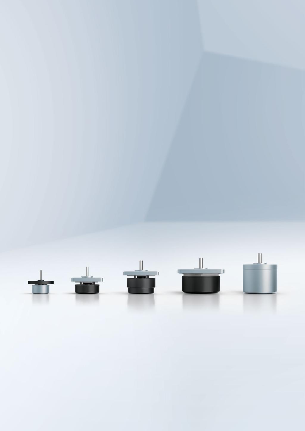
7 Overview of VD/VDC motors. Information VD/VDC motors Brushless external rotor motors VD/VDC VD-25.7 (p. 14) VD-35.6 (p. 16) VD-43.1 (p. 18) VD (p. 2) VD (p. 22) VDC-43.1 (p. 24) VDC (p. 26) VDC (p. 28) VDC (p. 3) VDC (p. 3) U N V DC M N mnm P W n N rpm l mm d mm (integrated) (from page 1) K1 (Hall sensor system) K3 (speed) K4 (position) (external) (from page 34) VTD-XX.XX-K3 VTD-XX.XX-K4S VTD-6.13-K5 SB Gearheads (from page 42) NoiselessPlus 63 (planetary gearhead) (p. 44) Performax 63 (planetary gearhead) (p. 46) Performax Plus 63 (planetary gearhead) (p. 48) EtaCrown 75 (crown gearhead) (p. 5) EtaCrown Plus 63 (crown gearhead) (p. 52) Compactline 9 (spur gearhead) (p. 54) Compactline 91 (spur gearhead) (p. 56) Compactline 92 (spur gearhead) (p. 58) Flatline 85 (spur gearhead) (p. 6) Gearheads Subject to alterations Standard type Preferred type: ready to ship in 48 hours With our preferred type products, we offer a selection of motors and gear motors which are available and ready to ship within 48 hours. Preferred type products can be ordered with a maximum order quantity of 2 products per order. With standard type products, we refer to a wide range of motors and gear motors which can be ordered using the stated order numbers with standard delivery times. Further products for your project requirements are available on request. These products are generally available but cannot be ordered by means of an allocated material number. We reserve the right to make changes to the necessary order numbers after technical and economic evaluation of the requirement. General information 7 ebm-papst around the world
8 8

9 VD/VDC motors. VD-25.7-K1 14 VD-35.6-K1 16 VD-43.1-K1 18 VD K1 2 VD K1 22 VDC-43.1-K3 24 VDC K3 26 VDC K3 28 VDC K4 3 General information Gearheads Information VD/VDC motors 9 ebm-papst around the world


10 Information for VD/VDC motors. Key figures 3-phase, electronically commutated external rotor motor Output range between 5 and 125 watts High power density realized in a compact design Very quiet operation across the entire speed range High overload capacity Very high power density Rigid speed / torque curve Extremely wide speed control range Robust housing and bearings Protection class IP 54 as per EN : up to IP 65 Approvals Support with the accreditation of products in different economic areas and markets As an experienced and competent partner we would be happy to support you Possible approvals include CE, CCC, UL, CSA, EAC Additional approvals on request Various motor types which can be combined with planetary, crown and spur gearheads Logic and power electronics Magnet Winding 1
11 Information The data in this catalog contain product specifications, but are not a guarantee of particular properties. All information is based on the measuring conditions mentioned below. Operation of motors using reference electronics at an ambient temperature of max. 4 C when attached (thermally conductive) to a free-standing steel plate of the following size: Steel plate 15 x 15 x 1 mm The nominal operating point is the basis for the electromagnetic design of the motor from the point of view of the maximum possible continuous output of the motor and is specified by the nominal values described here. The values mentioned are typical values for the design in question and are also subject to the tolerances included in the specifications or drawings. Unless otherwise stated, the supplements and safety notes contained in the relevant operating and assembly instructions must be kept at all times. Subject to availability and technical alterations. Nominal output power P N [W] The output power which the motor can produce continuously; it is calculated from nominal torque and nominal speed. For the electromagnetic design of the motor the determination of the nominal operating point is based on the fact that the nominal output power is close the maximum output power of the motor. Nominal voltage U BN, U N, U B [V DC] The DC voltage (i.e. DC voltage range) that is applied to the commutation electronics as a system supply voltage. All nominal values listed in the technical tables of the individual motors refer to this voltage. Motor applications are, however, not restricted to this voltage. Nominal speed n N [rpm] The speed at which the motor may be operated continuously while delivering nominal torque at an ambient temperature of 4 C and nominal output torque. It is an operating point on the max. motor curve based on an ideal electronics with negligible losses. Nominal torque M N [mnm] The torque that the motor can deliver continuously at an ambient temperature of 4 C and nominal speed. Speed n [min -1 ] , 1 M N M Max 9 16, ,3 6 1, 5 4 6, ,3 1 Continuous operation Torque M [mnm] The illustrated curves are idealized representations based on the figures in the tables. Nominal current I BN The current that is drawn from the system supply when the motor delivers nominal torque at nominal speed. Speed at no-load operation n L [rpm] The speed that takes effect at the nominal voltage and with unloaded motor. The theoretical possible speed at no-load operation can, in some cases, be limited by the mechanical ceiling speed. No-load current I BL [A] Is established with nominal voltage and unloaded motor; is largely influenced by the bearing friction. For drive systems that have a separate supply for power and logic, the no-load current is called I L. This no-load current is the sum of the power supply (I ZK ) and the low-power logic supply (I B ). Permanent stall torque M Bn [mnm] Is the maximum permissible torque with which the motor may be permanently loaded when the rotor is locked. Permissible eff. continuous stall current I neff [A] Is the maximum permissible current which at a stalled motor is allowed to flow into the motor lead as an effective value. Current I [A] Efficiency [%] 11 ebm-papst around the world General information Gearheads VD/VDC motors
12 Definitions for VD/VDC motors. Continuous stall power P Bn [W] Is an approximate value for the voltage-independent maximum permitted output (P=U x I) that can be taken from the DC voltage source in holding status. Permissible peak torque short-term M max [mnm] Is the torque which the motor can usually deliver in a short time. Permissible peak current, motor lead I max [A] Is the current that must flow in to the motor lead as a peak value to achieve the short-time peak torque. Induced voltage U imax [V/1 rpm] Maximum value of the induced voltage between two motor leads at 1 rpm. It is a dimension for the electromagnetic utilization of the motor. Connection resistance R v [Ohm] The winding resistance that is measured at 2 C between any two of three winding terminations. Connection inductance L V [mh] The average inductance that is measured at 2 C between any two of three winding terminations using a sinusoidal wave measuring frequency of 1 khz. Rotor moment of inertia J R [kgm 2 x1-6 ] The mass moment of inertia of the rotor and necessary dimension for the dynamic characteristics of the motor. Protection class Information on the protection class; it describes protection against foreign particles (Point 1) and water (Point 2). Permissible ambient temperature range T U [ C] Defines the minimum and maximum permissible ambient temperature to which the mentioned performance values apply when the motor is in operation. The permissible winding temperature in the motor (115 C for insulation Class E, as per EN ) </1125 should not be exceeded. Weight [kg] Weight of the delivered unit without additional units or packaging. Max. shaft load F radial /F axial [N] The permissible forces are divided into radial and axial load values. They are based on the maximum permissible values for the motor bearing during operation at normal rating and a defined service life expectancy L 1. Service life L 1 The values for the L 1 service life specified in conjunction with the permitted bearing loads have been calculated to DIN ISO 281. In addition to the specified values, this calculation is based on operation of the motor at nominal conditions (nominal torque, nominal speed) and an ambient temperature of max. 4 C. Therefore, the service life information is explicitly not a guarantee of service life, but strictly a theoretical quality figure. Max. reverse voltage [V DC] When the braking function is activated and when the set value step change is negative, the motor operates in controlled braking mode. In this operating state, the large part of the braking energy is fed back to the intermediate circuit until the max. reverse voltage is reached and the electronics prevent a further increase beyond this value by chopped braking. This behavior should be given special consideration when selecting the system supply. Set value input Speed setting via an analogue interface for DC voltage. Depending on the drive design, the set speed can be configured in a range from... n max, where the minimum possible speed value (with limited control quality) is about rpm (sine commutation) or approx. 5 to 1 rpm (block commutation). (Relevant only for drives with integrated operating electronics). Recommended speed range [rpm] Speed control range within which the speed control accuracy stipulated in the system specification is complied with. 12
13 Information Starting torque [mnm] Is the torque that can be delivered over a short time when the motor is started based on the electromagnetic motor characteristics and the set current limitation. VD/VDC motors Effective torque M eff [mnm] For cycle operation (e.g. S5 operating mode intermittent duty with the effect of the startup losses and the losses due to electrical braking on the heating), the effective torque corresponding to continuous operation ( S1 operating mode) is determined according to the following formula: M eff = M A 2 t A + M L 2 t B + M Br 2 t Br t A + t B + t Br + t St M A Starting torque M Br Braking t A Acceleration time t Br Braking time M L Load torque t St Standstill time t B Load period Gearheads At an ambient temperature of 4 C this effective torque must not be greater than the nominal torque MN listed in the catalog for the selected motor. For intermittent operation (operating mode S3 with tr = relative on period) the following permissible load moment applies: M L = M N 1 t r System selection When selecting a motor and operating for a drive system, consideration should be given to the fact that the values permitted for the motor should not be exceeded by the electronics. Likewise, the relationship shown in the commutation sequences between the sequence of Hall signals and the corresponding switching times and switching states of the output stage at the phase supply lines must be observed in order to attain optimum operation of the motor. General information Please contact the manufacturer if the products are operated or stored under non standard environmental conditions. 13 ebm-papst around the world

14 VD motor. VD-25.7-K1 3-phase external rotor motor with EC technology Basic motor with electronic module K1 for operation on external control electronics Very good synchronization characteristics Long lifetime by using precision ball bearings Insulation class E Electrical connection via socket directly on the circuit board Alternative windings / motor part sets on request Nominal data Type VD-25.7-K1-B1 Nominal voltage (U N ) V DC 24 Nominal speed (n N )* rpm 6 Nominal torque (M N )* mnm 8. Nominal current (I N )* A.4 Nominal output power (P N )* W 5. Starting torque (M max ) mnm 4. Permissible peak current (I max )** A 1.8 Speed at no-load operation (n L ) rpm 8 5 No-load current (I L ) A.95 Recommended speed control range rpm Rotor moment of inertia (J R ) kgm 2 x Motor constant (K E ) mvs/rad 26.6 Connection resistance (R V ) Ω 14.8 Connection inductance (L V ) mh 8. Overload protection To be implemented via the control electronics Permissible ambient temperature range (T U ) C Weight kg.55 Order no. IP Subject to alterations * At T U max. 4 C ** Permissible time for peak current: max. 1 sec. to be repeated only after complete cool down Characteristic curve VD-25.7-K1-B1 (at 25 C) , 1 M N M Max 9 1,8 8 7 Speed n [min -1 ] 7 5 5,6,4 Current I [A] Efficiency [%] 3 2 5,2 2 Continuous operation Torque M [mnm] 1 1) Nominal data, see table 14

15 Information Technical drawing All dimensions in mm 12 (x3) Ø 48 Ø 41 Ø Ø ±,5 max ±,2 -.5 Ø Ø VD/VDC motors 3x hole* for M2.5 2±.1 2±.3 * For thread-rolling screws according to DIN 75 Fradial L1 Faxial F axial 5 N F radial 5 N L1 1 mm Electrical connection Supply wire No. Function Signal wire No. Function Gearheads 6 Phase U 1 GND 7 Phase V 2 Hall C 8 Phase W U B 4 Hall B 5 Hall A Modular construction kit Recommended external control electronics VTD-XX.XX-K3 On request Basic motor General information 21 view (see electrical connection) Permissible shaft load at nominal speed and life expectancy L 1 (nominal operation) of 2 h (at T U max. 4 C) For motor-gearbox combinations, depending on the choice of the single components, the maximum allowable torque (gearbox) can be exceeded or respectively not reached. 15 ebm-papst around the world

16 VD motor. VD-35.6-K1 3-phase external rotor motor with EC technology Basic motor with electronic module K1 for operation on external control electronics Very good synchronization characteristics Long lifetime by using precision ball bearings Insulation class E Electrical connection via the circuit board edge plug Alternative windings / motor part sets on request Nominal data Type VD-35.6-K1-B1 VD-35.6-K1-B Nominal voltage (U N ) V DC 24 Nominal speed (n N )* rpm Nominal torque (M N )* mnm Nominal current (I N )* A Nominal output power (P N )* W Starting torque (M max ) mnm 69. Permissible peak current (I max )** A Speed at no-load operation (n L ) rpm No-load current (I L ) A Recommended speed control range rpm Rotor moment of inertia (J R ) kgm 2 x Motor constant (K E ) mvs/rad Connection resistance (R V ) Ω Connection inductance (L V ) mh Overload protection To be implemented via the control electronics Permissible ambient temperature range (T U ) C Weight kg.12 Order no. IP Subject to alterations * At T U max. 4 C ** Permissible time for peak current: max. 1 sec. to be repeated only after complete cool down Characteristic curve VD-35.6-K1-B1 (at 25 C) VD-35.6-K1-B (at 25 C) 12 5 M N M Max 4, M N 4, 1 M Max , , Speed n [min -1 ] ,4 1,6 Current I [A] Efficiency [%] Speed n [min -1 ] ,4 1,6 Current I [A] Efficiency [%] , , Continuous operation Continuous operation Torque M [mnm] Torque M [mnm] 1) Nominal data, see table 1) Nominal data, see table 16
 of 2 h (at T U max.")

17 -.5 Information Technical drawing All dimensions in mm R 5 57± ±.1 28±1 7.2± VD/VDC motors Ø ± ±.5 Ø Ø 4-.1 Ø ±.5 Ø Fradial L1 Faxial F axial 5 N F radial 2 N L1 1 mm Permissible shaft load at nominal speed and life expectancy L 1 (nominal operation) of 2 h (at T U max. 4 C) Electrical connection Supply wire No. Function 6 Phase W 7 Phase V 8 Phase U Signal wire No. Function 1 + U B 2 GND 3 Hall C 4 Hall B 5 Hall A Gearheads Modular construction kit Recommended external control electronics VTD-XX.XX-K3 On request Basic motor Rotor protection cap (page 66) General information 17 ebm-papst around the world
18 VD motor. VD-43.1-K1 3-phase external rotor motor with EC technology Basic motor with electronic module K1 for operation on external control electronics Very good synchronization characteristics Long lifetime by using precision ball bearings Insulation class E Electrical connection via the circuit board edge plug Alternative windings / motor part sets on request Nominal data Type VD-43.1-K1-B1 VD-43.1-K1-B Nominal voltage (U N ) V DC 24 Nominal speed (n N )* rpm Nominal torque (M N )* mnm Nominal current (I N )* A Nominal output power (P N )* W Starting torque (M max ) mnm 11 Permissible peak current (I max )** A Speed at no-load operation (n L ) rpm No-load current (I L ) A Recommended speed control range rpm Rotor moment of inertia (J R ) kgm 2 x Motor constant (K E ) mvs/rad Connection resistance (R V ) Ω Connection inductance (L V ) mh Overload protection To be implemented via the control electronics Permissible ambient temperature range (T U ) C Weight kg.24 Order no. IP Subject to alterations * At T U max. 4 C ** Permissible time for peak current: max. 1 sec. to be repeated only after complete cool down Characteristic curve VD-43.1-K1-B1 (at 25 C) VD-43.1-K1-B (at 25 C) 12 5 M N M Max 6, M N 6, 1 M Max , , Speed n [min -1 ] ,6 2,4 Current I [A] Efficiency [%] Speed n [min -1 ] ,6 2,4 Current I [A] Efficiency [%] , , Continuous operation Continuous operation Torque M [mnm] Torque M [mnm] 1) Nominal data, see table 1) Nominal data, see table 18
 of 2 h (at T U max. 4 C) Electrical connection Supply wire No.")
19 Information Technical drawing All dimensions in mm R ± ± ± Ø 5-.1 VD/VDC motors Ø ± ±.5 Ø 52,8±.1 Ø ±.5 Ø Fradial L1 Faxial F axial 9 N F radial 35 N L1 1 mm Permissible shaft load at nominal speed and life expectancy L 1 (nominal operation) of 2 h (at T U max. 4 C) Electrical connection Supply wire No. Function 6 Phase W 7 Phase V 8 Phase U Signal wire No. Function 1 + U B 2 GND 3 Hall C 4 Hall B 5 Hall A Gearheads Modular construction kit Recommended external control electronics VTD-XX.XX-K3 On request Basic motor Spur gearheads Compactline 91 (page 56) VTD-6.13-K5SB On request rotor protection cap (page 66) Connection cables (page 67) General information 19 ebm-papst around the world
20 VD motor. VD K1 3-phase external rotor motor with EC technology Basic motor with electronic module K1 for operation on external control electronics Very good synchronization characteristics Long lifetime by using precision ball bearings Insulation class E Electrical connection via the circuit board edge plug Nominal data Type VD K1-B1 VD K1-B Nominal voltage (U N ) V DC 24 Nominal speed (n N )* rpm Nominal torque (M N )* mnm 15 Nominal current (I N )* A Nominal output power (P N )* W Starting torque (M max ) mnm 4 Permissible peak current (I max )** A Speed at no-load operation (n L ) rpm No-load current (I L ) A Recommended speed control range rpm Rotor moment of inertia (J R ) kgm 2 x Motor constant (K E ) mvs/rad Connection resistance (R V ) Ω Connection inductance (L V ) mh Overload protection To be implemented via the control electronics Permissible ambient temperature range (T U ) C Weight kg.52 Order no. IP Subject to alterations * At T U max. 4 C ** Permissible time for peak current: max. 1 sec. to be repeated only after complete cool down Characteristic curve VD K1-B1 (at 25 C) VD K1-B (at 25 C) 8 M N 1, 1 M Max 8 M N 1, 1 M Max 7 8, , , ,5 8 7 Speed n [min -1 ] ,25 5, 3,75 Current I [A] Efficiency [%] Speed n [min -1 ] ,25 5, 3,75 Current I [A] Efficiency [%] 2 2, , , ,25 1 Continuous operation Continuous operation Torque M [mnm] Torque M [mnm] 1) Nominal data, see table 1) Nominal data, see table 2
 of 2 h (at T U max. 4 C) Electrical connection Supply wire No.")
21 12± ±.5 Information Technical drawing All dimensions in mm R7 82± ±.1 42±1 7.2± VD/VDC motors -.5 Ø 6-.1 Ø 68.4±.1 Ø Ø Ø ±.5 Fradial L1 Faxial F axial 9 N F radial 6 N L1 1 mm Permissible shaft load at nominal speed and life expectancy L 1 (nominal operation) of 2 h (at T U max. 4 C) Electrical connection Supply wire No. Function 6 Phase W 7 Phase V 8 Phase U Signal wire No. Function 1 + U B 2 GND 3 Hall C 4 Hall B 5 Hall A Gearheads Modular construction kit Recommended external control electronics VTD-XX.XX-K3 Speed (page 34) Basic motor Spur gearheads Compactline 9 (page 54) VTD-XX.XX-K4S Position (page 36) Compactline 91 (page 56) VTD-6.13-K5SB Position (page 38) Compactline 92 (page 58) Spur gearheads Flatline 85 (page 6) General information Rotor protection cap (page 66) Connection cables (page 67) 21 ebm-papst around the world
22 VD motor. VD K1 3-phase external rotor motor with EC technology High poled motor structure for optimum power density Basic motor with electronic module K1 for operation on external control electronics Very good synchronization characteristics Robust mechanical design in IP 54 for industrial applications Long lifetime by using precision ball bearings Insulation class E Electrical connection via cable Nominal data Type VD K1-B VD K1-D Nominal voltage (U N ) V DC Nominal speed (n N )* rpm Nominal torque (M N )* mnm Nominal current (I N )* A Nominal output power (P N )* W Starting torque (M max ) mnm Permissible peak current (I max )** A Speed at no-load operation (n L ) rpm 6 No-load current (I L ) A Recommended speed control range rpm... 6 Rotor moment of inertia (J R ) kgm 2 x Motor constant (K E ) mvs/rad Connection resistance (R V ) Ω Connection inductance (L V ) mh Overload protection To be implemented via the control electronics Permissible ambient temperature range (T U ) C Weight kg.59 Order no. (cable type)*** IP Subject to alterations * At T U max. 4 C ** Permissible time for peak current: max. 1 sec. to be repeated only after complete cool down *** Classification of protection class refers to installed state with sealing on the flange side Characteristic curve VD K1-B (at 25 C) VD K1-D (at 25 C) 8 M N 4 1 M Max 8 M N 4 1 M Max Speed n [min -1 ] Current I [A] Efficiency [%] Speed n [min -1 ] Current I [A] Efficiency [%] Continuous operation Continuous operation Torque M [mnm] Torque M [mnm] 1) Nominal data, see table 1) Nominal data, see table 22
 of 2 h (at T U max.")

23 Information Technical drawing All dimensions in mm Ø 63±.2 Ø 5 Ø 4 52±.5 2±.3 2,5±.1 VD/VDC motors 3x12 Ø 25h8 +.1 Ø x hole* M4 * For thread-rolling screws according to DIN 75 R 35 24± ± ±5 Fradial Faxial L1 5±1 F axial 2 N F radial 6 N L1 1 mm 24±.5 Permissible shaft load at nominal speed and life expectancy L 1 (nominal operation) of 2 h (at T U max. 4 C) Electrical connection Supply wire No. Color Function 1 yellow Phase W 2 violet Phase V 3 brown Phase U Signal wire No. Color Function 1 2 red +12 V 3 white Hall B Gearheads Molex plug no Molex plug no green Hall A black GND 8 gray Hall C Modular construction kit Recommended external control electronics Basic motor Planetary gearheads VTD-XX.XX-K3 Speed (page 34) NoiselessPlus 63 (page 44) VTD-XX.XX-K4S Position (page 36) Performax 63 (page 46) VTD-6.13-K5SB Position (page 38) Performax Plus 63 (page 48) Crown gearheads EtaCrown 75 (page 5) EtaCrown Plus 63 (page 52) General information Spur gearheads Compactline 91 (page 56) Flatline 85 (page 6) 23 ebm-papst around the world

24 VDC motor. VDC-43.1-K3 3-phase external rotor motor with EC technology Drive with completely integrated K3 operation and control electronics Integrated speed control function Interface with analog and digital control inputs Very good synchronization characteristics Long lifetime by using precision ball bearings Electrical connection via the circuit board edge plug Nominal data Type VDC-43.1-K3-B1 VDC-43.1-K3-B Nominal voltage (U N ) V DC 24 Nominal speed (n N )* min Nominal torque (M N )* mnm 45 Nominal current (I N )* A Nominal output power (P N )* W Starting torque (M max ) mnm 67 Speed at no-load operation (n L ) min No-load current (I L ) A.4.14 Recommended speed control range min Rotor moment of inertia (J R ) kgm 2 x1 6 4 Overload protection integrated Permissible ambient temperature range (T U ) C Weight kg.24 Order no. IP Subject to alterations * At T U max. 4 C Characteristic curve VDC-43.1-K3-B1 (at 25 C) VDC-43.1-K3-B (at 25 C) 12 5 M N 7, 1 M Max 12 5 M N 7, 1 M Max , , Speed n [min -1 ] ,2 2,8 Current I [A] Efficiency [%] Speed n [min -1 ] ,2 2,8 Current I [A] Efficiency [%] , , Continuous operation Continuous operation Torque M [mnm] Torque M [mnm] 1) Nominal data, see table 1) Nominal data, see table 24
25 Information Technical drawing All dimensions in mm R ± ±.1 4± ± Ø 6-.9 VD/VDC motors Ø ± ±.5 view (see electrical connection) Fradial L1 Faxial F axial 9 N F radial 35 N L1 1 mm Electrical connection Supply wire No. Configuration 7 GND 8 U B Signal wire Nr. Configuration Function 1 OUT Pulse output (speed) 2 D-IN-A Input 3 D-IN-B Input 4 C 5 A-IN...1V (differential) Gearheads 6 A-GND GND for analog IN for differential Modular construction kit Connection cables (page 67) Basic motor Spur gearheads Compactline 91 (page 56) General information Ø 52.8±.1 Ø Capacitor 2±.5 Ø Permissible shaft load at nominal speed and life expectancy L 1 (nominal operation) of 2 h (at T U max. 4 C) 25 ebm-papst around the world
26 VDC motor. VDC K3 3-phase external rotor motor with EC technology Drive with completely integrated K3 operation and control electronics Integrated speed control function Interface with analog and digital control inputs Very good synchronization characteristics Long lifetime by using precision ball bearings Electrical connection via the circuit board edge plug Nominal data Type VDC K3-B1 VDC K3-B Nominal voltage (U N ) V DC 24 Nominal speed (n N )* min Nominal torque (M N )* mnm 1 15 Nominal current (I N )* A Nominal output power (P N )* W Starting torque (M max ) mnm 12 Speed at no-load operation (n L ) min No-load current (I L ) A Recommended speed control range min Rotor moment of inertia (J R ) kgm 2 x Overload protection integrated Permissible ambient temperature range (T U ) C Weight kg.52 Order no. IP Subject to alterations * At T U max. 4 C Characteristic curve VDC K3-B1 (at 25 C) VDC K3-B (at 25 C) 9 M N 6, 1 M Max 9 6, 1 M Max 8 5, , ,7 8 7 M N 4, , 7 6 4, 7 Speed n [min -1 ] ,3 2,7 2, Current I [A] Efficiency [%] Speed n [min -1 ] ,3 2,7 2, Current I [A] Efficiency [%] 2 1, ,3 2 1,7 1 1,7 1 Continuous operation Continuous operation Torque M [mnm] Torque M [mnm] 1) Nominal data, see table 1) Nominal data, see table 26
27 Information Technical drawing All dimensions in mm R7 82± ±.1 42±1 7.2± VD/VDC motors Ø Ø ± ±.5 Ø 68.3±.1 Ø Fradial L1 Faxial F axial 9 N F radial 6 N L1 1 mm 2.5±.5 Ø view (see electrical connection) Permissible shaft load at nominal speed and life expectancy L 1 (nominal operation) of 2 h (at T U max. 4 C) Electrical connection Supply wire No. Configuration 7 GND 8 U B Signal wire Nr. Configuration Function 1 OUT Pulse output (speed) 2 D-IN-A Input 3 D-IN-B Input 4 C 5 A-IN...1V (differential) Gearheads 6 A-GND GND for analog IN for differential Modular construction kit Rotor protection cap (page 66) Connection cables (page 67) Basic motor Spur gearheads Compactline 9 (page 54) Compactline 91 (page 56) Compactline 92 (page 58) Spur gearheads Flatline 85 (page 6) General information 27 ebm-papst around the world

28 VDC motor. VDC K3 3-phase external rotor motor with EC technology High-poled motor structure for optimum power density. Drive with completely integrated K3 operation and control electronics Integrated speed control function Interface with analog and digital control inputs Very good synchronization characteristics Robust mechanical design in IP 54 for industrial applications Long lifetime by using precision ball bearings Electrical connection via cable with free wire ends Nominal data Type VDC K3-B VDC K3-D Nominal voltage (U N ) V DC Nominal speed (n N )* min 1 4 Nominal torque (M N )* mnm Nominal current (I N )* A Nominal output power (P N )* W Starting torque (M max ) mnm 3 56 Speed at no-load operation (n L ) min 1 4 No-load current (I L ) A.4.25 Recommended speed control range min Rotor moment of inertia (J R ) kgm 2 x Overload protection integrated Permissible ambient temperature range (T U ) C Weight kg.59 Order no. (cable type)** IP Subject to alterations * At T U max. 4 C ** Classification of protection class refers to installed state with sealing on the flange side Characteristic curve VDC K3-B (at 25 C) VDC K3-D (at 25 C) 5 M N 8, 1 M Max 5 M N 6, 1 M Max 4 5 7, , , , , ,2 7 Speed n [min -1 ] ,8 4, 3,2 Current I [A] Efficiency [%] Speed n [min -1 ] ,6 3, 2,4 Current I [A] Efficiency [%] 1 5 2, , , ,2 2 5,8 1 5,6 1 Continuous operation Continuous operation Torque M [mnm] Torque M [mnm] 1) Nominal data, see table 1) Nominal data, see table 28
29 Technical drawing All dimensions in mm Information Ø 63±.2 Ø 5 Ø 4 52±.5 2±.3 2.5±.1 3x12 R 35 grooves for O-ring 44.65±.5 4±.5 twisted and tin-plated +.1 Ø 8+.6 Ø 25h8 VD/VDC motors 6x hole* M4 * For thread-rolling screws according to DIN 75 24±.2 Electrical connection / cable with open wires 85±5 Ø7.2±.15 24±.5 5±1 Fradial F axial Faxial L1 2 N F radial 6 N L1 1 mm Permissible shaft load at nominal speed and life expectancy L 1 (nominal operation) of 2 h (at T U max. 4 C) Signal Power Wire color Configuration Function Blue GND Logic power/signal GND Pink S1 to 1 V speed set Point Green TXD Communication / programming interface White RXD Communication / programming interface Grey-Pink A Control input A, TTL level Violet B Control input B, TTL level Grey IST Actual value 1 Red-Blue F+ Frequency specification for speed setpoint Brown S2 to +5 V current limitation (torque) Black C Control input C hardware enable Red E Actual value 2 Yellow D Drive status Blue GND Power supply GND Brown +U B Logic power supply Black U ZK Power supply Recommended AWG Gearheads Modular construction kit Basic motor Planetary gearheads NoiselessPlus 63 (page 44) Performax 63 (page 46) Performax Plus 63 (page 48) Crown gearheads EtaCrown 75 (page 5) EtaCrown Plus 63 (page 52) General information Spur gearheads Compactline 91 (page 56) Flatline 85 (page 6) 29 ebm-papst around the world
30 VDC motor. VDC K4 3-phase external rotor motor with EC technology High-poled motor structure for optimum power density. Drive with completely integrated K4 operation and control electronics Integrated speed, torque and position control Selection of operating modes and parameter setting via RS485 Interface with analog and digital control inputs Integrated brake chopper Robust mechanical design in IP 54 for industrial applications Electrical connection via cable with free wire ends Nominal data Type VDC K4-B VDC K4-D Nominal voltage (U N ) V DC Nominal speed (n N )* min 1 4 Nominal torque (M N )* mnm Nominal current (I N )* A Nominal output power (P N )* W Starting torque (M max ) mnm 75 9 Permissible peak current (I max )** A Speed at no-load operation (n L ) min 1 5 No-load current (I L ) A.4.25 Recommended speed control range min Rotor moment of inertia (J R ) kgm 2 x Overload protection integrated Permissible ambient temperature range (T U ) C Weight kg.59 Order no. (cable type)*** IP Subject to alterations * At T U max. 4 C ** Permissible time for peak current: max. 1 sec. to be repeated only after complete cool down Preferred type: ready to ship in 48 hours *** Classification of protection class refers to installed state with sealing on the flange side Characteristic curve VDC K4-B (at 25 C) VDC K4-D (at 25 C) 6 M N 2, 1 M Max 6 M N 2, 1 M Max , , , ,3 7 Speed n [min -1 ] 3 2 1, 6,7 Current I [A] Efficiency [%] Speed n [min -1 ] 3 2 1, 6,7 Current I [A] Efficiency [%] 1 3, , Continuous operation Continuous operation Torque M [mnm] Torque M [mnm] 1) Nominal data, see table 1) Nominal data, see table 3
31 Technical drawing All dimensions in mm Information Ø 63±.2 Ø 5 Ø 4 52±.5 2±.3 2.5±.1 3x12 R 35 grooves for O-ring 44.65±.5 4±.5 twisted and tin-plated +.1 Ø 8+.6 Ø 25h8 VD/VDC motors 6x hole* M4 * For thread-rolling screws according to DIN 75 24±.2 Electrical connection / cable with open wires 85±5 Ø7.2±.15 24±.5 5±1 Fradial F axial Faxial L1 2 N F radial 6 N L1 1 mm Permissible shaft load at nominal speed and life expectancy L 1 (nominal operation) of 2 h (at T U max. 4 C) Signal Power Wire color Configuration Function white D-IN-A NPN 24 V brown D-IN-B NPN 24 V green D-IN-1 NPN 24 V yellow D-IN-2 NPN 24 V / analog... 1 V / brake gray D-OUT-1 PNP 24 V pink D-OUT-2 PNP 24 V blue Must not be used red A-IN V (differential) black A-GND GND for analog IN 1 (differential) violet RS485 A (+) Progr. bus gray / pink RS485 B ( ) Progr. bus red / blue U Logic Logic power supply (24 V) gray Ballast Ballast resistor brown U ZK Power supply black GND Power / signal GND Recommended AWG Gearheads Modular construction kit Basic motor Planetary gearheads NoiselessPlus 63 (page 44) Performax 63 (page 46) Performax Plus 63 (page 48) Crown gearheads EtaCrown 75 (page 5) EtaCrown Plus 63 (page 52) General information Spur gearheads Compactline 91 (page 56) Flatline 85 (page 6) 31 ebm-papst around the world

32 32
33 . VTD-XX.XX-K3 (speed) 34 VTD-XX.XX-K4S (position) 36 VTD-6.13-K5SB (CANopen) 38 General information Gearheads Information VD/VDC motors 33 ebm-papst around the world

34 . VTD-XX.XX-K3 Operating electronics for driving 3-phase BLDC motors from the VD-43.1 / VD and VD series. Design in digital technology for use as OEM electronics in series applications Motor commutation and speed control via microcontroller Control parameters are each specifically designed for the motor Four-quadrant controller Speed setting via analog nominal value... 1 V DC Speed actual value processing and output Setting of the operating mode via 2 control inputs Monitoring function for output current and voltage Nominal data Type VTD-24.XX-K3 VTD-48.XX-K3 Nominal voltage (power supply U N ) V DC Permissible supply voltage range (U) V DC Permissible continuous output current* A 3-12 depending on model 3-6 depending on model Maximum commutation frequency khz 2 Switching frequency khz 2 Minimum connection inductance mh.1 Digital inputs Number 2 Digital outputs Number 1 Analog inputs Number 1 Efficiency (in optimum working range) % 95 Permissible ambient temperature range (T U ) C Permissible ambient humidity** % Protection class IP Weight kg.2 Order number On request On request Subject to alterations Commutation: block commutation (by means of 3 digital Hall sensors) * Applicable at rated temperature T U = 4 C ** Condensation not permitted 34
35 Technical drawing All dimensions in mm VD/VDC motors Information Electrical connection Pin Control plug X3 Motor plug X4 Capacitor plug X5 1 A Operating mode L3 Motor phase U+ Capacitor connector 2 +U B Operating voltage +U-Hall Hall sensor supply U- Capacitor connector 3 n.c. Not allocated RLG2 Hall signal 2 BR Braking resistor 4 S+ Set value input RLG1 Hall signal 1 5 B Operating mode L2 Motor phase 2 6 Actual Actual speed value L1 Motor phase 1 7 GND Ground GND Hall Ground Hall sensor supply 8 S- Ground set value input RLG3 Hall signal 3 Gearheads Connection cables X3 Color assignment Type Order no. No. Color Function X3 Control plug white (AWG 2) A 5±1 3±.5 Stripped, twisted and tin-plated red (AWG 18) +U B 3 violet (AWG 2) n.c. 4 green (AWG 2) S+ 5 gray (AWG 2) B 6 yellow (AWG 2) Actual 7 black (AWG 18) GND 8 brown (AWG 2) S- General information View without wires 35 ebm-papst around the world

36 . VTD-XX.XX-K4S Operating electronics for driving 3-phase BLDC motors up to 1 watt output power Four-quadrant controller Speed, torque and positioning mode Selection of operating modes and parameter setting via RS 485 User-friendly parameter setting with Kickstart PC software Integrated brake ballast-control Device status notification by 2 LEDs Nominal data Type VTD-24.4-K4S VTD-48.2-K4S Nominal voltage (power supply U N ) V DC Permissible supply voltage range (U) V DC Maximum output current (max. 5 sec)* A 1 Permissible continuous output current* A 4 ± 1% 2 ± 1% Nominal voltage (Logic supply U L ) V DC 24 Logic current draw** (at 24 V DC) ma < 1 Maximum commutation frequency khz 2 Switching frequency khz 2 Minimum connection inductance mh.1 Digital inputs Number 4 Digital outputs Number 3 Analog inputs Number 1 Parameterization interface RS 485 Efficiency (in optimum working range) % > 95 Permissible ambient temperature range (T U ) C Permissible ambient humidity*** % Protection class IP 2 Weight kg approx..5 Order number (IP 2) Subject to alterations * Applicable at rated temperature T U = 25 C, Derating at deviating (higher) temperatures ** Current draw without current requirement of digital outputs Series planned for 2nd q/217 *** Condensation not permitted 36
 FE Ballast U 2 D-OUT-2 GND RS485 B (-) P-GND V 3 D-OUT-3 Hall A RS485 A (+) U ZK W 4 U Logic")
 Kickstart PC software for commissioning/ parametrization of the drive controller Controller Power supply PC with Kickstart software General information Interface adapter Order no.")
37 Information Technical drawing All dimensions in mm VD/VDC motors X 16 X 17 X 1 X 12 Status LEDs 157 X 11 Mating connectors are included in delivery Electrical connection Pin X1 Signals Logic supply X11 Hall sensors X12 Parameterization interface X16 Power supply, controller 1 D-OUT-1 +U Hall (5V) FE Ballast U 2 D-OUT-2 GND RS485 B (-) P-GND V 3 D-OUT-3 Hall A RS485 A (+) U ZK W 4 U Logic Hall B FE FE 5 GND Hall C 6 FE (Functional earth) +U sin/cos (5V) 7 D-IN-A GND 8 D-IN-B SIN 9 D-IN-1 COS 1 D-IN-2 FE 11 A-IN-1 12 A-IN-GND X17 Power supply, motor Gearheads Commissioning tool Kickstart (page 64) Kickstart PC software for commissioning/ parametrization of the drive controller Controller Power supply PC with Kickstart software General information Interface adapter Order no Image of Kickstart PC software Commissioning setup Motor VDC-49.XX-K1 37 ebm-papst around the world
 Integrated digital inputs Integrated digital outputs Integrated analog inputs")
38 . VTD-6.13-K5SB Compact four-quadrant controller for BLDC motors CANopen interface (Protocol DS31, Device profile DS42) Integrated digital inputs Integrated digital outputs Integrated analog inputs Overvoltage, undervoltage and overtemperature monitoring Device status notification by 3 LEDs (Power, Status, Error) Hex switch for setting the device node ID Freely programmable due to built in MPU (Motion Process Unit) Nominal data Type VTD-6.13-K5SB Nominal voltage (Power supply U N ) V DC Permissible supply voltage range (U) V DC Maximum output current* A 5 Permissible continuous output current* A 12.5 (at 24 V) 12.5 (at 24 V) Nominal voltage (Logic supply U L ) V DC Logic current draw** (at 24 V DC) ma 6 Maximum commutation frequency khz 2 Switching frequency khz 32 Minimum connection inductance mh.2 Digital inputs Number 8 Digital outputs Number 2 Analog inputs Number 2 Parameterization interface CANopen Efficiency (in optimum working range) % 95 Permissible ambient temperature range (T U ) C Permissible ambient humidity*** % Protection class IP 2 Weight kg.31 Order number (IP 2) Subject to alterations Commutation: block commutation (by means of 3 digital Hall sensors) * Applicable at rated temperature T U = 25 C, Derating at deviating (higher) temperatures ** Current draw without current requirement of digital outputs *** Condensation not permitted 38
39 Technical drawing All dimensions in mm VD/VDC motors Information Mating connectors are included in delivery Electrical connection Pin X1 Motor X2 Hall sensors and encoder X3 I/O's and CAN X4 I/O's Power supply 1 FE Functional earth H1 Hall sensor signal 1 U Logic Electronics A-IN-1 Analog input 1 2 +Up Power supply Power H2 Hall sensor signal 2 A-IN- + Analog input, plus D-IN-4 Digital input 4 3 GND Ground for power supply voltage H3 Hall sensor signal 3 D-IN- Digital input D-IN-5 Digital input 5 4 Ma Motor phase A A Incremental encoder A channel D-IN-1 Digital input 1 D-IN-6 Digital input 6 5 Mb Motor phase B B Incremental encoder B channel D-IN-2 Digital input 2 D-OUT-1 Digital output 1 6 Mc Motor phase C Inx Incremental encoder index channel D-IN-3 Digital input 3 D-IN-7 Digital input 7 7 +U 5V 5V auxiliary voltage (Hall and encoder) GND Ground for electronic supply voltage 8 /H1 Hall sensor signal 1 inverted A-IN- - Analog input, minus 9 /H2 Hall sensor signal 2 inverted D-OUT- Digital output 1 /H3 Hall sensor signal 3 inverted CAN Hi CAN High 11 /A Incremental encoder A channel inverted CAN Lo CAN Low 12 /B Incremental encoder B channel inverted CAN GND CAN Ground 13 /Inx Incremental encoder index channel inverted 14 GND Ground for auxiliary voltage Gearheads Commissioning tool EP-Tools (page 65) PC with software EP-Tools General information Motor VDC K1 Interface adapter Arrangement Commissioning 39 ebm-papst around the world
40 4
 44 Performax 63 (planetary gearhead) 46 Performax Plus 63 (planetary gearhead) 48 EtaCrown 75 (crown gearhead) 5 EtaCrown Plus 63 (crown gearhead) 52 Compactline")
41 Gearheads. NoiselessPlus 63 (planetary gearhead) 44 Performax 63 (planetary gearhead) 46 Performax Plus 63 (planetary gearhead) 48 EtaCrown 75 (crown gearhead) 5 EtaCrown Plus 63 (crown gearhead) 52 Compactline 9 (spur gearhead) 54 Compactline 91 (spur gearhead) 56 Compactline 92 (spur gearhead) 58 Flatline 85 (spur gearhead) 6 Information on operating factor, lifetime, efficiency 7 General information Gearheads Information VD/VDC motors 41 ebm-papst around the world


42 Information for gearheads. In the gearbox product range, we offer three types of transmission technologies. These include planetary gearing, crown gearhead units and spur gears, all individually adapted to the requirements of the customer according to the modular principle. Deciding which of these technologies will render the best results for the respective application, ultimately depends on the application itself. Characteristics of the individual transmission technologies: Planetary gearheads Higher reduction ratios within first and second stage Very quiet operation Extremely high performance Compact design No offset axle Comprehensive range of products with three model types - Noiseless Plus unique quiet operation - Performax extreme performance - Optimax robust and long lifetime Crown gearheads Outstanding efficiency Large reduction ratio range No self-locking Highest power density No offset axle Two different model ranges - EtaCrown - EtaCrown Plus Spur gearheads Highest power density Flat, compact design Large reduction ratio range High radial loads permitted Good price/performance ratio Two different model ranges - Flat-line - Compact-line 42
43 Information The comprehensive range of planetary gearbox products is used when the application does not allow axle misalignment. When it comes to achieving high efficiency with minimal noise, the NoiselessPlus is the impressive obvious choice. Exemplary smooth running is achieved thanks to extremely sturdy, low-wear plastic planetary wheels in an aluminium housing with bevelled teeth. Double ball bearing output shafts efficiently absorb the forces acting on the shaft at high radial loads. The output shafts of the NoiselessPlus gearheads are made of hardened and ground case-hardened steel and are thus particularly durable. Performax is an innovative, patent-pending concept of high-performance planetary gearheads. With its pioneering design, Performax gearheads are popular for their outstanding power density, ultimate smoothness and unique reduction ranges. Transmissions of up to 17:1 in one stage allow the use of single-stage gearheads, whereas competitors products already require a two-stage design. The design features of the series include helical plastic gear wheels in the first stage and in the second stage, straight toothing in the zinc diecast casting with case-hardened planetary wheels. Another special standard feature of Performax gearheads is the planetary wheels of the second stage. These have needle bearings, which really sets the series apart from the regular planetary gearheads available on the market. EtaCrown is the name of the innovative angular gear with crown gearhead technology. Our vision of making crown gearheads smaller, more powerful and more efficient, and above al to manufacture them more economically, is now a reality. EtaCrown significantly improves energy efficiency and cost-effectiveness of drive solutions. The modular design can be flexibly adapted for any drive task. Characteristic is its very compact design and space-saving geometry with a symmetrical structure and maximum performance density. Transmissions of 4:1 to 113:1 are available as standard. Also standard is jolt-free start-up due to rolling tooth gripping. Smooth running due to intelligent gear-tooth technology and gearhead design, while maximum radial load thanks to double-sided support of the drive shaft are also part of its features. A special feature among angular drives is the self-locking capacity, which does not exist in the technology. In contrast to other gearbox technologies, this offers optimal protection against vandalism. The range of gearboxes is rounded off by the spur gearhead systems of the Flatline and Compactline series. In the first transmission stage, these have helically toothed plastic wheels, thus achieving optimum noise reduction. The following gear stages are optimally configured in terms of running noise and torque to be transferred. Ground and hardened output shafts and hardened gearwheels are standard in all Flatline series gearheads. Die-cast zinc is used as a housing material. Gearheads of the Flatline design are particularly suitable for use in applications with limited installation lengths. In drives of the Compactline series, where the wheel widths were dimensioned in order to minimise noise particularly in the first stage, due attention was paid to having the greatest possible wheel width and therefore to a good contact ratio between the motor shaft and the combing gearwheel. General information Gearheads VD/VDC motors 43 ebm-papst around the world
44 Planetary gearheads. NoiselessPlus 63 Very quiet operation due to helical-tooth gear stages Toothed parts made of plastic with optimized sliding properties ensure smooth operation Higher reduction ratios within first and second gear stage High radial loads due to double ball bearing in the output shaft Flexible connection to customer applications (shaft variants, centering and fastening) Image of 1-stage gearhead Nominal data Gearheads NoiselessPlus 63.1 NoiselessPlus 63.2 Reduction ratio No. of stages 1 2 Efficiency.9.81 Max. input speed (n 1 ) rpm 6 6 Rated output torque (M ab ) Nm Short-term torque (M max ) Nm Gear play Permissible operating temperature (T U ) C Operating mode S1 S1 Protection class IP 5 IP 5 Weight kg.56.8 Shaft load radial / axial N 5 / 1 5 / 1 5 / 1 1 / 1 78 / 1 1 / / / 1 Service life h 1 1 Lubrication Maintenance-free grease lubrication for life Installation position any Subject to alterations Preferred type: ready to ship in 48 hours on request 44
45 Technical drawing Image of 1-stage gearhead / All dimensions in mm Information VD/VDC motors Fradial L1 Faxial F axial F radial L1 1 N see table 19 mm Permissible shaft load at nominal speed and life expectancy L 1 (nominal operation) and operating factor C B = 1 (see page 7) of 1 h (at T U 4 C). Gearheads Length of the possible motor / gearhead combinations Motor / gearhead L - 1-stage L - 2-stage VD K1-NP63 mm VDC K3-NP63 mm VDC K4-NP63 mm Subject to alterations General information 45 ebm-papst around the world

46 Planetary gearheads. Performax 63 High power density from compact dimensions Very quiet operation due to helical teeth in the first gear stage Planetary wheels made of plastic with optimized sliding properties in the first stage ensure smooth operation Large effective diameter thanks to radial screw connection Economical setup due to use of many individual parts which are readily available on the market Image of 1-stage gearhead Nominal data Gearheads Performax 63.1 Performax 63.2 Reduction ratio No. of stages 1 2 Efficiency.9.81 Max. input speed (n 1 ) rpm 6 6 Rated output torque (M ab ) Nm Short-term torque (M max ) Nm Gear play Permissible operating temperature (T U ) C Operating mode S1 S1 Protection class IP 5 IP 5 Weight kg.4.6 Shaft load radial / axial N 35 / 5 35 / 5 Service life h 5 5 Lubrication Maintenance-free grease lubrication for life Installation position any Subject to alterations Preferred type: ready to ship in 48 hours on request 46
47 Technical drawing Image of 1-stage gearhead / 2-stage design completely cylindrical / All dimensions in mm Information VD/VDC motors Fradial L1 Faxial F axial F radial L1 5 N 35 N 19 mm Permissible shaft load at nominal speed and life expectancy L 1 (nominal operation) and operating factor C B = 1 (see page 7) of 5 h (at T U 4 C). Gearheads Length of the possible motor / gearhead combinations Motor / gearhead L - 1-stage L - 2-stage VDC K3-P63 mm VDC K4-P63 mm Subject to alterations General information 47 ebm-papst around the world
48 Planetary gearheads. Performax Plus 63 High torques thanks to large gearing width in the first gear stage Good shock resistance due to housing made of case-hardened steel with linear tooth profile in the output stage Very quiet operation due to helical teeth in the first gear stage Planetary wheels made of plastic with optimized sliding properties in the first stage ensure smooth operation Large effective diameter thanks to radial screw connection Image of 2-stage gearhead Nominal data Gearheads Performax Plus 63.1 Performax Plus 63.2 Reduction ratio No. of stages 1 2 Efficiency.9.81 Max. input speed (n 1 ) rpm 6 6 Rated output torque (M ab ) Nm Short-term torque (M max ) Nm Gear play Permissible operating temperature (T U ) C Operating mode S1 S1 Protection class IP 5 IP 5 Weight kg Shaft load radial / axial N 35 / 5 35 / 5 Service life h 5 5 Lubrication Maintenance-free grease lubrication for life Installation position any Subject to alterations Preferred type: ready to ship in 48 hours on request 48
49 Technical drawing Image of 1-stage gearhead / 2-stage design completely cylindrical / All dimensions in mm Information VD/VDC motors Fradial L1 Faxial F axial F radial L1 5 N 35 N 19 mm Permissible shaft load at nominal speed and life expectancy L 1 (nominal operation) and operating factor C B = 1 (see page 7) of 5 h (at T U 4 C). Gearheads Length of the possible motor / gearhead combinations Motor / gearhead L - 1-stage L - 2-stage VDC K3-PP63 mm VDC K4-PP63 mm Subject to alterations General information 49 ebm-papst around the world

50 Crown gearheads. EtaCrown 75 Maximum safety in design and operation, as well as optimal vandalism protection; no automatic lock due to high efficiency of the crown wheel technology Space-saving installation due to zero offset axle and symmetrical structure Flexible application possibilities with various optional shaft outlets and available shaft geometries Wide reduction range by means of upstream / downstream planetary stage High radial loads due to double ball bearing in the output shaft Image of 2-stage gearhead Nominal data Gearheads EtaCrown 75.1 EtaCrown 75.2 Reduction ratio No. of stages 1 2 Efficiency.9.81 Max. input speed (n 1 ) rpm 6 6 Rated output torque (M ab ) Nm Short-term torque (M max ) Nm Gear play Permissible operating temperature (T U ) C Operating mode S1 S1 Protection class IP 5 IP 5 Weight kg Shaft load radial / axial N 15 / 5 25 / 5 4 / 5 55 / 5 8 / / / 5 Service life h 5 5 Lubrication Maintenance-free grease lubrication for life Installation position any Subject to alterations Preferred type: ready to ship in 48 hours on request 5
51 Technical drawing Image of 1-stage gearhead with right shaft end (W5) / All dimensions in mm Information VD/VDC motors Fradial L1 Faxial F axial F radial L1 5 N see table 15 mm Permissible shaft load at nominal speed and life expectancy L 1 (nominal operation) and operating factor C B = 1 (see page 7) of 5 h (at T U 4 C). Gearheads Shaft end, right (W5) (standard) Shaft end, left (W6) Shaft end, both sides (W7) Hollow shaft (W8) Hollow shaft Ø 1 mm Length of the possible motor / gearhead combinations Motor / gearhead L - 1-stage L - 2-stage VDC K4-E75 mm Subject to alterations General information 51 ebm-papst around the world

52 Crown gearheads. EtaCrown Plus 63 Compact design due to combination of the crown wheel and planetary stage in one housing No automatic lock due to high efficiency of the crown wheel technology High torques by using 5 straight toothed planetary gears made of case-hardened sintered steel in the integrated planetary gear stage Wide reduction range thanks to possibility of an upstream planetary stage Improved quiet operation thanks to the optimized design of the crown wheel stage when using an upstream helical planetary gear stage made of plastic with optimized sliding properties Image of 3-stage gearhead Nominal data Gearheads EtaCrown Plus 63.3 Reduction ratio No. of stages 3 Efficiency.73 Max. input speed (n 1 ) rpm 6 Rated output torque (M ab ) Nm Short-term torque (M max ) Nm Gear play Permissible operating temperature (T U ) C Operating mode S1 Protection class IP 5 Weight kg 1. Shaft load radial / axial N 6 / 3 Service life h 5 Lubrication Maintenance-free grease lubrication for life Installation position any Subject to alterations Preferred type: ready to ship in 48 hours on request 52
53 Technical drawing Image of 3-stage gearhead / All dimensions in mm Information VD/VDC motors Fradial L1 Faxial F axial F radial L1 3 N 6 N 15 mm Permissible shaft load at nominal speed and life expectancy L 1 (nominal operation) and operating factor C B = 1 (see page 7) of 5 h (at T U 4 C). Gearheads Length of the possible motor / gearhead combinations Motor / gearhead L - 3-stage VDC K4-EP63 mm 177 Subject to alterations General information 53 ebm-papst around the world
54 Spur gearheads. Compactline 9 Minimum space requirement due to compact design High power density High torques from the smallest possible dimensions Very quiet operation thanks to optimized gear geometries and materials Maintenance-free over entire service life Nominal data Gearheads Compactline 9.2 Compactline 9.3 Compactline 9.4 Reduction ratio No. of stages Efficiency Max. input speed (n 1 ) rpm Rated output torque (M ab ) Nm Short-term torque (M max ) Nm Gear play Permissible operating temperature (T U ) C Operating mode S1 S1 S1 Protection class* IP 5 IP 5 IP 5 Weight kg Shaft load radial / axial N 12 / 4 12 / 4 12 / 4 Service life h Lubrication Maintenance-free grease lubrication for life Installation position any Subject to alterations * Classification of protection class refers to installed state with sealing on the flange side on request 54
55 Technical drawing All dimensions in mm Motor Information VD/VDC motors Fradial L1 Faxial F axial F radial L1 4 N 12 N 17 mm Permissible shaft load at nominal speed and a life expectancy L 1 (nominal operation) and operating factor C B = 1 (see page 7) of 5 h (at T U 4 C). Gearheads Length of the possible motor / gearhead combinations Motor / gearhead L VD-43.1-K1-C9 mm 81 VDC-43.1-K3-C9 mm 82 VD K1-C9 mm 84 VDC K3-C9 mm 84 Subject to alterations General information 55 ebm-papst around the world
56 Spur gearheads. Compactline 91 Minimum space requirement due to compact design High power density High torques from the smallest possible dimensions Very quiet operation thanks to optimized gear geometries and materials Maintenance-free over entire service life Nominal data Gearheads Compactline 91.2 Compactline 91.3 Reduction ratio (for motor 43.1 / 54.14) No. of stages (for motor 49.15) No. of stages 2 3 Efficiency Max. input speed (n 1 ) rpm 4 4 Rated output torque (M ab ) Nm Short-term torque (M max ) Nm Gear play Permissible operating temperature (T U ) C Operating mode S1 S1 Protection class* IP 5 IP 5 Weight kg.3.3 Shaft load radial / axial N 15 / 5 15 / 5 Service life h 5 5 Lubrication Maintenance-free grease lubrication for life Installation position any Subject to alterations * Classification of protection class refers to installed state with sealing on the flange side Preferred type: ready to ship in 48 hours on request 56
57 Technical drawing All dimensions in mm Motor Information VD/VDC motors Fradial L1 Faxial F axial F radial L1 5 N 15 N 17 mm Permissible shaft load at nominal speed and a life expectancy L 1 (nominal operation) and operating factor C B = 1 (see page 7) of 5 h (at T U 4 C). Gearheads Length of the possible motor / gearhead combinations Motor / gearhead L VD-43.1-K1-C91 mm 79 VDC-43.1-K3-C91 mm 79 VD K1-C91 mm 81 VDC K3-C91 mm 81 VDC K3-C91 mm 99 VDC K4-C91 mm 99 Subject to alterations General information 57 ebm-papst around the world

58 Spur gearheads. Compactline 92 Minimum space requirement due to compact design High power density High torques from the smallest possible dimensions Very quiet operation thanks to optimized gear geometries and materials Maintenance-free over entire service life Nominal data Gearheads Compactline 92.2 Compactline 92.3 Reduction ratio No. of stages 2 3 Efficiency Max. input speed (n 1 ) rpm 4 4 Rated output torque (M ab ) Nm Short-term torque (M max ) Nm Gear play Permissible operating temperature (T U ) C Operating mode S1 S1 Protection class* IP 5 IP 5 Weight kg.4.5 Shaft load radial / axial N 15 / 5 15 / 5 Service life h 5 5 Lubrication Maintenance-free grease lubrication for life Installation position any Subject to alterations * Classification of protection class refers to installed state with sealing on the flange side Preferred type: ready to ship in 48 hours on request 58
59 Technical drawing All dimensions in mm Information VD/VDC motors Fradial L1 Faxial F axial F radial L1 5 N 15 N 17 mm Permissible shaft load at nominal speed and a life expectancy L 1 (nominal operation) and operating factor C B = 1 (see page 7) of 5 h (at T U 4 C). Gearheads Length of the possible motor / gearhead combinations Motor / gearhead L VD K1-C92 mm 85 VDC K3-C92 mm 85 Subject to alterations General information 59 ebm-papst around the world

60 Spur gearheads. Flatline 85 Optimized installation length due to flat gear design Large reduction range Flexible connection to customer applications due to differ ent available output shafts Use of alternative toothing materials as standard Maintenance-free over entire service life Nominal data Gearheads Flatline 85.3 Flatline 85.4 Reduction ratio No. of stages 3 4 Efficiency Max. input speed (n 1 ) rpm 4 4 Rated output torque (M ab ) Nm Short-term torque (M max ) Nm Gear play Permissible operating temperature (T U ) C Operating mode S1 S1 Protection class* IP 5 IP 5 Weight kg.5.5 Shaft load radial / axial N 15 / 5 15 / 5 Service life h 5 5 Lubrication Maintenance-free grease lubrication for life Installation position any Subject to alterations * Classification of protection class refers to installed state with sealing on the flange side Preferred type: ready to ship in 48 hours on request 6
61 Technical drawing All dimensions in mm Motor VD/VDC motors Information Fradial L1 Faxial F axial F radial L1 5 N 15 N 17 mm L±1 Permissible shaft load at nominal speed and a life expectancy L 1 (nominal operation) and operating factor C B = 1 (see page 7) of 5 h (at T U 4 C). Gearheads Length of the possible motor / gearhead combinations Motor / gearhead Bestellzusatz LC1 für Motor- (Standard) C1-K2 C1-K3 VDC K3-F85 mm Anschraubposition 88 VDC K4-F85 mm 88 VDC K3-F85 mm 7 Subject Bestellzusatz to alterations C1 C1 C1 für für für Motor- (Standard) C1-K2 C1-K3 C1-K4 Order add-on Anschraubposition for motor mounting position VDC Gearhead VDC C2 VDC (Standard) C2-K2 C2-K3 C1-K4 C2-K4 VDC VDC VDC VDC C2 C2 C2 C2 (Standard) C2-K2 C2-K3 C2-K4 K1 K1 C2 (Standard) C2-K2 C2-K3 C2-K4 K1 (Standard) (Standard) K2 K2 K3 K4 General information VDC K1 K1 K1 (Standard) K2 K2 K2 K3 K3 K3 K4 K4 K4 61 ebm-papst around the world
62 62

63 . Commissioning tools General information Gearheads Information VD/VDC motors 63 ebm-papst around the world

64 Commissioning tools. K4 Parameterization and commissioning Automatic operation Automatic operation with stored parameters and integrated control Controller Power supply Controller Power supply PC with software Kickstart Interface adapter Order no Motor VDC-49.XX-K1 VDC-49.XX-K4 drive Commissioning setup The RS485 interface serves as an interface for parameterization and diagnosis. It can be operated using the freely available Kickstart PC software. This requires a PC and the ebm-papst USB-CAN-RS485 adapter. Load your detailed operating manual and the PC software Kickstart under Interface adapter for Kickstart PC software Order number USB-CAN-RS485 adapter Functional description of the LED displays LED name Color Function assignment Data Error microsd red green red green red green No assignment. Active data transfer via the USB-CAN-RS485 adapter. No response following request to K4. Receipt of a faulty data package. Received data is OK. No assignment. Access to the memory card. 64

65 Commissioning tools. K5 Information Parameterization and commissioning VD/VDC motors Interface adapter PC with software EP-Tools Motor VDC K1 Commissioning setup Gearheads Commissioning tool for EP-Tools PC software Order number USB to CANStick Functional description of the LED displays LED name Color Display Function assignment LED Power LED1 State LED2 Error LED3 Rx LED4 Tx green yellow red green yellow lights up does not light up flashes does not light up flashes lights up does not light up flashes does not light up flashes does not light up Normal operation No power supply Bootloader mode (no firmware) Normal operation Bootloader mode (flashes with incoming message) Error No error (normal operation) Flashes with incoming message No incoming message Flashes with outgoing message No outgoing message 65 General information ebm-papst around the world
66 . Rotor protection cap All dimensions in mm L1 L2 L3 Protection cap For type L1 L2 L3 Order no. VD-35.X VD VD
67 Information Technical drawing connection cables K1 All dimensions in mm VD/VDC motors 5± ± single wires / AWG 22 8 single wires / AWG 2 Connection cables Connection cables For type VD-35.6-K1 VD-43.1-K1 Order no For type Order no. VD K Gearheads Technical drawing connection cables K3 All dimensions in mm 5±2 3 ±5 1 3 ±5 5± single wires / AWG 22 Connection cables For type Order no. VDC-43.1-K single wires / AWG 2 Connection cables For type Order no. VDC K General information 67 ebm-papst around the world
68 Standards and guidelines. Basic information on standards and guidelines for electrical small-power motors and drive systems operated with a DC voltage of max. 75 V DC (nominal voltage): The VD/VDC series described in this catalog are direct current motors in an electronically commutated design, which are designed and specified for a nominal voltage of max. 75 V DC. Thus the supply voltage of these drives is within the range of safety extra-low voltage (SELV). On this basis, ebm-papst would like to provide some information intended to help you understand the classification of the motors from the relevant EC Directives and the resulting consequences. The CE label In order to ensure a uniform safety level in the European internal market, the European commission has implemented a new approach for technical harmonization. This has been welcomed by all relevant parties and is visible in many products as a CE label giving proof of agreement with the harmonized provisions. What does CE actually mean? Why don t all products bear the CE label? CE is the abbreviation for Communauté Européenne. The harmonized statutory provisions are a framework directive and belong to the so-called New Approach. This framework directive defines the basic requirements, putting in circulation and operation as well as the applicable conformity assessment process. The manufacturer of a product must now decide which framework directive applies to which product. For electrical small-powered motors the following framework directive can be applied: 1) Machinery Directive 26/42/EC 2) Low Voltage Directive 214/35/EU 3) EMC Directive 214/3/EU Based on these directives, ebm-papst St. Georgen GmbH & Co. KG does not mark the electric motors and drive systems described with the CE mark and does not issue an EC Declaration of Conformity. The reason for this is consideration of the relevant EC Directives and the definitions of the terms used, Electric motor and Drive system, by ebm-papst St. Georgen GmbH & Co. KG. Definition of the electric motor An electric motor is a motor without electronics or a motor with integrated electronics of low complexity, such as commutation sensors, simple commutation electronics or commutation electronics with simple speed control with a voltage range of <75 V DC (nominal voltage) for use by customers who incorporate them into end devices. According to this definition, electric motors include, for example, the VD/VDC-XX.XX-K1 series. Definition of drive systems Drive systems are motors with built-in electronic control systems that have a certain degree of complexity. These include electronic control systems which, in addition to a speed control, offer other functions such as current control or position control. This also includes electronic control systems which, for example, have a CANopen interface or that can be operated via programmable sequential controls. For these drive systems, the voltage range of <75 V DC (nominal voltage) and the intended use by customers who will use the systems in end devices also apply. Drive systems include the VDC-XX.XX-K3 and VDC-XX.XX-K4 series, for example. Reasons according to the Machinery Directive 26/42/EC Electric motors are expressly exempt in Art. 1, Par. (2), lit. k) and thus are NOT given the CE mark. According to the definition of the term in Art. 2, lit. g), a drive system is an incomplete machine and thus does not receive a CE mark, but falls under the process for incomplete machines according to Art. 13. Installation instructions to Annex IV and a Declaration of Incorporation to Annex II, Part 1, Section B are available for each drive system. The specific technical documents to Art. 13, Par. (1), lit. a) have been created in-house and are archived for the government agencies of the individual countries. Based on this directive, the machine manufacturer is responsible for verifying and ensuring compliance with the basic requirements of the Machinery Directive. Reasons according to the Low Voltage Directive 214/35/EU Due to the voltage ranges (nominal voltage), the specified electric motors and drive systems do not fall under the application area of the low voltage directive according to Art
69 Information Reasons according to the EMC Directive 214/3/EU Because they are sold exclusively to customers who incorporate them into end devices and not to the end user, the specified electric motors and drive systems do not fall under the application area of the EMC directive according to the definition of the term in Art. 3, Par. (2), 1: As the small motors are supplied to companies who incorporate them into end devices and not to the end user, ebm-papst has no control over further use of the pre-fabricated components in devices, machines or installations. Therefore, ebm-papst provides express notice that the system manufacturer must provide a suitable EMC circuit when selecting the power supply and must provide for EMC-compliant installation and use in the devices. For more information about EMC-compliant installation and EMC safety measures, refer to resources such as the IEC 61-5-x series (Installation and Mitigation Guidelines). Proper use All drives in this catalog are determined for installation in permanently connected, stationary end devices and machines in the industrial area and must be operated on electricity only when in installed condition! Operation is prohibited until it has been ascertained that this product, along with the machine into which this product is to be installed, complies with the protective requirements of the Machinery Directive. If, when using our drives, market or application-specific product standards apply, compliance with these must be verified and ensured by the device manufacturer. This product is not intended for the end consumer. RoHS European Directive EC No. 211/65/EU (RoHS) Legally regulated substances As an innovative company and trendsetter in the world of air technology and drive engineering, ebm-papst feels a special obligation towards the environment. Accordingly, under the GreenTech logo, we have implemented a comprehensive concept that extends from the origin to the use of our products. This includes, of course, protecting our environment and using natural resources in a way that conserves them. This applies equally to our manufacturing processes and to our products. When developing our products, we already take into consideration any possible negative consequences they may have for the environment. Our goal is to prevent such environmental impact-even beyond the extent mandated by law-or to reduce it to a minimum, and thus to ensure sustainable development of our products. Thus we ensure that our products are free of materials and substances that are prohibited by law. Of course, all current products have been designed for conformity with European Directive 211/65/EU (RoHS). All older products that do not yet conform to these directives or parts thereof will be consistently redesigned. Our suppliers are required to provide us only with goods that conform to the directives. Thus we can confirm that basically, all of our products listed in this catalog conform to the above-mentioned directive. We are also available to help with any other questions you may have on both these topics. REACH Directive (EC No. 197/26) The EU legal regulation for Registration, Evaluation, Authorization and Restriction of Chemical substances (REACH) entered into force on 1 June 27. This is a chemicals law intended to provide maximum protection to health and the environment. As defined by the REACH directive, ebm-papst is a downstream user. The units you purchase from us are products as defined by REACH and thus do not require registration. However, in our own interest and to ensure a high degree of product safety, we track the implementation of REACH and the resulting requirements as part of our duty to provide information. To comply with the requirements of REACH, we are in contact with all suppliers from whom we obtain chemicals (substances), preparations and components that we use as part of our production process. Within this framework, ebm-papst fulfills the obligations set forth in the REACH regulation. If you have any other questions about the implementation of the REACH directive in our company, please do not hesitate to contact us. 69 ebm-papst around the world General information Gearheads VD/VDC motors
70 Operating factor, lifetime, efficiency. Operating factor c B To achieve a uniform lifetime for the gearheads and motors, the necessary torques M must be increased by the respective operating factor c B under the various operating loads so as not to exceed the maximum permissible gearhead torque M 2 max (see table below). Operating modes Load Operating period in h/days 3 h 8 h 24 h 3 h 8 h 24 h even gradual sudden up to 1 switching ops./h over 1 switching ops./h One rotation direction Rotation direction change One rotation direction Rotation direction change One rotation direction Rotation direction change Operating mode It is necessary to define the operating mode under which a gear motor can be operated with certain nominal values in order to avoid overloading the motor and / or the gearhead. The values stated in this catalog refer to S1 operation (continuous operation). This means that the gear motor can be constantly operated with the stated values, but can also have a higher load placed on it for a short time. Please contact us if you require more information about this. Lifetime Lifetime is limited by the various components in the drive. If frequently overloaded, the gearhead components are subjected to more wear than under nominal load. Extreme ambient and operating conditions cause a reduction in the lifetime guaranteed for operation under operating ratio c B = 1. Efficiency η (eta) The efficiency per gear stage is at least 9%. Depending on the tooth configuration and on the manufacturing quality, far better levels of efficiency can also be achieved. The following overall efficiencies were obtained for multi-stage gearheads: Overall efficiency for 1-stage gearhead η =.9 for 2-stage gearhead η =.9 2 =.81 for 3-stage gearhead η =.9 3 =.73 for 4-stage gearhead η =.9 4 =.66 for 5-stage gearhead η =.9 5 =.59 7
71 General information Gearheads VD/VDC motors Information 71 ebm-papst around the world

72 Region in Germany. Region north Region Middle / East Region Central / West Region South / East 1 Region South / West Region South / East 2 72
Brushless internal rotor motors ECI series. Drive solutions Industrial drive engineering
 Brushless internal rotor motors ECI series Drive solutions Industrial drive engineering Modular drive systems. Motors with integrated logic and power electronics optional gearhead, encoder and brake. Contents.
Brushed internal rotor motors BCI series. Drive solutions Industrial drive engineering
 Brushed internal rotor motors BCI series Drive solutions Industrial drive engineering Modular drive systems. Motors optional with gearhead, encoder and brake. 2 Contents. Information About ebm-papst 4
Motors- Basic principles. Expertise, performance, innovation
 Motors- Basic principles Expertise, performance, innovation As a leading supplier of ventilation and drive engineering technology, ebm-papst is a highly respected engineering partner in many industries.
Drive Concept for SIMATIC MICRO-DRIVE
 Product Catalog -4 the engineer s choice About ebm-papst ebm-papst is a leader in ventilation and drive engineering technology and a much sought-after engineering partner in many industries. With around,
VARIODRIVE 3-phase external rotor motor. VARIODRIVE technical information VARIODRIVE
 27.05.20 0: Seite Information Antriebstechnik_20_05_27_Finale_EN_:Vorlage VarioDrive C ECI motor 5 AC motors VARIODRIVE -phase external rotor motor Specifications 4 Representatives VARIODRIVE technical
Product overview Motors and drive systems. Industrial drive technology
 Product overview Motors and drive systems Industrial drive technology About ebm-papst. As technological leader for ventilation and drive engineering, ebm-papst is in demand as an engineering partner in
Product overview Motors and drive systems. Industrial drive technology
 Product overview Motors and drive systems Industrial drive technology About ebm-papst. As technological leader for ventilation and drive engineering, ebm-papst is in demand as an engineering partner in
K4 drive systems Brilliantly versatile. Drive solutions Industrial drive engineering
 K4 drive systems Brilliantly versatile Drive solutions Industrial drive engineering 217-11 About ebm-papst. As technological leader for ventilation and drive engineering, ebm-papst is in demand as an engineering
Product overview Motors and drive systems. Industrial drive technology 2016
 Product overview Motors and drive systems Industrial drive technology 2016 About ebm-papst. As a leader in technologies for ventilation and drive engineering, ebm-papst is in demand as an engineering partner
Sensorless Brushless DC-Servomotors
 Sensorless Brushless DC-Servomotors FAULHABER Brushless DC-Servomotors are built for extreme operating conditions. They are precise, have exceptionally long lifetimes and are highly reliable. Outstanding
Note: All windings shown are standard configuration. Please contact Motion Technologies for availability of all others
 Table of content Theory 3 1) Brushless Motor MTFL22RBL Series 4 MTFL28BL Series 5 MTFL33BL Series 6 MTFL36RBL Series 7 MTFL42RBL Series 8 MTFL42BL Series 9 MTFL42BLSH Series 10 MTFL57BL Series 11 MTFL57BLSH
Standard-efficiency gas heating. Innovation is our tradition.
 Standard-efficiency gas heating. Innovation is our tradition. About ebm-papst. As a leader in technologies for ventilation and drive engineering, ebm-papst is in demand as an engineering partner in many
3242 G 024 BX4 CS/CC 24 3,6 18,2 77,3 1,6 / 12,4 9 / ball bearings, preloaded 0,015. stainless steel 370 electronically reversible
 Brushless DC-Servomotor with integrated Motion Controller and or CN interface 6 mnm For combination with Gearheads: 3/1, 32, 32/3, 32/3 S, 38/1, 38/1 S, 38/2, 38/2 S 3242... BX4 CS/CC 1 2 3 4 Nominal voltage
Press News. Silent, dynamic and powerful: The new motor series ECI Compact by ebm-papst
 Press News Silent, dynamic and powerful: The new motor series ECI 42.40 Compact by ebm-papst All-inclusive: The turn-key drive solutions The electronically commutated ECI 42.40 Compact, with a nominal
2232 S 024 BX4 CSD/CCD 24 12,4 6,4 67,7 2 / 17 4,1 / ball bearings, preloaded 0,015. stainless steel 77 electronically reversible
 NEW Brushless DC-Servomotor with integrated Motion Controller and or CN interface 18 mnm For combination with Gearheads: 22F, 22/7, 26 2232... BX4 CSD/CCD 1 2 3 4 Nominal voltage Terminal resistance, phase-phase
Series 7000 Torque Sensor for PTO-shafts
 Properties PTO (Power Take-Off) shaft with integrated torque and angle measurement Non-contact measurement system, high robustness Special for PTO shafts 1 ¾ und 1 3/8 Plug & Play solution, no additional
Series 7000 Torque Sensor for PTO-shafts
 Properties PTO (Power Take-Off) shaft with integrated torque and angle measurement Non-contact measurement system, high robustness Special for PTO shafts 1 ¾ und 1 3/8 Plug & Play solution, no additional
Power in new dimensions
 NEW FAULHABER BXT Power in new dimensions WE CREATE MOTION EN Angaben zu Lebensdauer sowie weitere technische Erläuterungen 1 FAULHABER BXT Today, you don't find visionary designs in Hollywood, but rather
Brushless internal rotor motors with low-backlash planetary gears. Drive solutions Industrial drive engineering
 Brushless internal rotor motors with low-backlash planetary gears Drive solutions Industrial drive engineering 218-6 218-6 2 ECI motors Information about ECI motors Definitions for ECI motors ECI-42.XX-K1
ILE1F661PC1A0 brushless dc motor V - CANopen DS301 interface - L = 122 mm - w/o gearbox
 Characteristics brushless dc motor 24..36 V - CANopen DS301 interface - L = 122 mm - w/o gearbox Main Range of product Product or component type Device short name Motor type Number of motor poles 6 Network
HBI 22. Integrated Three-phase Synchronous Drive
 HBI 22 Integrated Three-phase Synchronous Drive positioning capability up to 9 Watts rated output power with linear hall sensor system with or without parking brake Motor type Dimension L1 L2 HBI 223 125
Quiet-running family of products with the lowest torque pulsation
 Press release Highly dynamic, 3-phase internal rotor motor for industrial applications Quiet-running family of products with the lowest torque pulsation For industrial systems and devices, compact motors
Online data sheet DFS60B-S4CA08192 DFS60 INCREMENTAL ENCODERS
 Online data sheet DFS60B-S4C08192 DFS60 B C D E F Illustration may differ Detailed technical data Performance Ordering information Type Part no. DFS60B-S4C08192 1038099 Other models and accessories www.sick.com/dfs60
Demag KB conical-rotor brake motors. Drives with unique principle
 Demag KB conical-rotor brake motors Drives with unique principle 37468 Demag KB conical rotor brake motors: Demag KB conical rotor brake motors offered by Demag Cranes & Components feature a unique principle:
ILE2K661PC1A1 brushless dc motor V- EtherNet/IP interface - L = 174 mm- 18:1
 Characteristics brushless dc motor 24..48V- EtherNet/IP interface - L = 174 mm- 18:1 Main Range of product Product or component type Device short name Motor type Number of motor poles 6 Network number
RadiPac EC centrifugal fans. New dimensions in efficiency: sizes 630 1,000
 RadiPac EC centrifugal fans. New dimensions in efficiency: sizes 630 1,000 A coherent concept. RadiPac stands for Realistic performance specifications, as the performance data of the entire fan is continuously
3-phase stepping motors
 General Series of Features from Berger Lahr are: Powerful because the optimised internal geometry results in a high power intensity, meaning up to 50 % more torque than standard stepping motors of comparable
antriebstechnik Standard Modular System 2011 NEMA connections it s time for tomorrow
 antriebstechnik Standard Modular System 2011 NEMA connections it s time for tomorrow NEMA-Connection for spur and planetary gearheads Flexibility for many applications: The intelligent modular system.
Customised drive solutions
 Customised drive solutions Electric motors & systems Drive components Services Introduction 03 Halm quality drive technology Over 50 years of experience in developing electric motors with asynchronous
premo servo actuators
 servo actuators 20 21 the powerful servo actuator platform Absolute precision meets perfect motion: combines precision with motion more efficiently than ever. The central idea behind the first fully scalable
Drive technology for AC and DC
 Drive technology for AC and DC version 2011 The engineer s choice Innovations for the future The right product for every requirement Trendsetters in drive technology Welcome to ebm-papst, the leaders and
Online data sheet DFS60B-S4EL00800 DFS60 INCREMENTAL ENCODERS
 Online data sheet DFS60B-S4EL00800 DFS60 B C D E F Illustration may differ Detailed technical data Performance Ordering information Type Part no. DFS60B-S4EL00800 1053600 Other models and accessories www.sick.com/dfs60
The new fan generation S-Force
 The new fan generation S-Force S-Force The Ultimate Performer The strongest team in the league The S-Force series is composed of five smaller series with sizes from 80 to 172 mm. Each is the world champion
SINAMICS GM150 IGCT version
 /2 Overview /2 Benefits /2 Design /6 Function /8 Selection and ordering data /8 Options Technical data /14 General technical data /15 Control properties /15 Ambient conditions /16 Installation conditions
ILE1F661PB1A0 brushless dc motor V - CANopen DS301 interface - L = 122 mm - w/o gearbox
 Characteristics brushless dc motor 24..36 V - CANopen DS301 interface - L = 122 mm - w/o gearbox Product availability : Stock - Normally stocked in distribution facility Price* : 840.00 USD Main Range
Online data sheet DFS60B-S4PC10000 DFS60 INCREMENTAL ENCODERS
 Online data sheet DFS60-S4PC10000 DFS60 DFS60-S4PC10000 DFS60 C D E F H I J K L M N O P Q R S T Ordering information Type Part no. DFS60-S4PC10000 1036721 Other models and accessories www.sick.com/dfs60
DYNASYN Hightorque-Servomotors DT Dynamic. Compact. Powerful.
 DYNASYN Hightorque-Servomotors DT Dynamic. Compact. Powerful. Top-class dynamic response: DT compact high-torque motors The DYNASYN DT series of high-torque motors meets the highest requirements made by
SINAMICS SM150. 4/2 Overview. 4/2 Benefits. 4/2 Design. 4/6 Function. 4/8 Selection and ordering data. 4/8 Options
 /2 Overview /2 Benefits /2 Design /6 Function /8 Selection and ordering data /8 Options Technical data /1 General technical data /15 Control properties /15 Ambient conditions /16 Installation conditions
Lexium integrated drives
 Description ILp for CANopen, PROFIBUS DP, RS ILE with brushless DC motor Description ILE comprise control electronics with a fieldbus interface for CANopen DS, PROFIBUS DP or RS and a brushless DC motor.
RadiPac EC radial impellers Perfection in air handling
 RadiPac EC radial impellers Perfection in air handling The engineer s choice One-stop shopping A coherent concept RadiPac stands for... Real Information - The performance documentation for the entire fan,
USER-PROGRAMMABLE AND ROBUST
 NC FREELY PROGRAMMABLE ROTARY TABLES NC ROTARY TABLE NC ROTARY TABLE: USER-PROGRAMMABLE AND ROBUST OPTIMISED BEARINGS To achieve maximum quality and reliability, even when under load, all roller bearings
Lenze. Global Drive 9300 servo inverters kw
 401 870 Global Drive 9300 servo inverters 0.37 75 kw 9300 servo inverter flexible and modern automation High-performance 9300 servo inverters with a matching motor program form a perfect drive system.
ILA2D572TC1F0 integrated drive ILA with servo motor V - DeviceNet - indus connector
 Characteristics integrated drive ILA with servo motor - 24..48 V - DeviceNet - indus connector Main Range of product Product or component type Device short name Motor type Number of motor poles 6 Phase
4,5 / 27 2,0 / steel, black coated. clockwise, viewed from the front face. ø15,9 ø17-0,052 ø6-0,05. ø3,5 8,1 ±0,3 2, T
 DC-Micromotors Precious Metal Commutation mnm For combination with (overview on page 4-5) Gearheads: 5, 6, 6/7 Encoders: IE 6... 5 Series 3 4 77... SR Nominal voltage Terminal resistance Output power Efficiency
DYNASYN DD servo motors. Dynamic. Compact. Energy-efficient.
 DYNASYN DD servo motors. Dynamic. Compact. Energy-efficient. B E N E F I T S Maximum dynamic response Increased energy efficiency High cost effectiveness Long service life Single-cable solution 2 DYNASYN
Low voltage AC drives
 General machinery drives Main features and dimensions Unique features Fast and extensive I/O PID control Application macros Many installation possibilities 200 to 480 V, 1-phase or 3-phase More value for
Motor/Drive Configuration
 ZX900 Electrical Specifications Input Power Output Power Electrical specifications for the ZX900 series drive's input and output power are provided in this section. Voltage (Nominal) Voltage (Range) Frequency
INTELLIGENT FLANGE STRÖTER. Magnetic pulse generator
 INTELLIGENT FLANGE STRÖTER agnetic pulse generator Incremental magnetic pulse generator addons to drive systems is now possible in an easy and economical way both in new and existing installations. The
Precision Modules PSK
 Precision Modules PSK The Drive & Control Company Rexroth Linear Motion Technology Ball Rail Systems Roller Rail Systems Standard Ball Rail Systems Super Ball Rail Systems Ball Rail Systems with Aluminum
QMOT Motor QBL4208 Manual 42mm QMOT BLDC motor family
 QMOT Motor QBL4208 Manual 42mm QMOT BLDC motor family Trinamic Motion Control GmbH & Co. KG Sternstraße 67 D 20357 Hamburg, Germany http://www.trinamic.com QBL4208 Manual (V1.01 / 2008-04-01) 2 Table of
Stepper motors EMMS-ST
 q/w Worldwide: Superb: Easy: Festo core product range Covers 80% of your automation tasks Always in stock Festo quality at an attractive price Reduces procurement and storing complexity qgenerally ready
Stepper motors EMMS-ST
 q/w Worldwide: Superb: Easy: Festo core product range Covers 80% of your automation tasks Always in stock Festo quality at an attractive price Reduces procurement and storing complexity qready for dispatch
Permanent magnet brakes. Safety from the market leader. PM Line High Torque Line
 Permanent magnet brakes Safety from the market leader PM Line High Torque Line Industrial Drive Systems Die Welt von Kendrion Industrial Drive Systems Kendrion The brake experts As a solution provider,
MAKES LIGHT WORK OF HEAVY LOADS
 CR/TH FREELY PROGRAMMABLE ROTARY TABLES CR/TH HEAVY DUTY ROTARY TABLE CR/TH HEAVY DUTY ROTARY TABLE: MAKES LIGHT WORK OF HEAVY LOADS FOR HORIZONTAL AXES User-programmable rotary barrel drive of the TH
Compact, dynamic and rugged
 Compact, dynamic and rugged Direct drives for harsh operation conditions SIOTICS T Heavy Duty Torque otors Brochure Edition arch 2016 SIOTICS T Heavy Duty Torque otors Overview In many machining processes
Compact Modules. with ball screw drive and toothed belt drive R310EN 2602 ( ) The Drive & Control Company
 The Drive & Control Company") with ball screw drive and toothed belt drive R310EN 2602 (2007.02) The Drive & Control Company Bosch Rexroth AG Linear Motion and Assembly Technologies Ball Rail Systems Roller Rail Systems Linear Bushings
with ball screw drive and toothed belt drive R310EN 2602 (2007.02) The Drive & Control Company Bosch Rexroth AG Linear Motion and Assembly Technologies Ball Rail Systems Roller Rail Systems Linear Bushings
EMC-HD. C 01_2 Subheadline_15pt/7.2mm
 C Electromechanical 01_1 Headline_36pt/14.4mm Cylinder EMC-HD C 01_2 Subheadline_15pt/7.2mm 2 Elektromechanischer Zylinder EMC-HD Short product name Example: EMC 085 HD 1 System = ElectroMechanical Cylinder
Scroll down to view your document!
 Over 100 years cumulative experience 24 hour rush turnaround / technical support service Established in 1993 The leading independent repairer of servo motors and drives in North America. Visit us on the
Application Information
 Moog Components Group manufactures a comprehensive line of brush-type and brushless motors, as well as brushless controllers. The purpose of this document is to provide a guide for the selection and application
ILE2T661PB1A3 brushless dc motor V - Modbus TCP interface - L = 174 mm - 54:1
 Characteristics brushless dc motor 24..48 V - Modbus TCP interface - L = 174 mm - 54:1 Product availability : Non-Stock - Not normally stocked in distribution facility Price* : 1540.00 USD Main Range of
SERIES PR90H PROGRAMMABLE INCREMENTAL HOLLOW SHAFT ENCODER FOR INDUSTRIAL APPLICATIONS REFERENCE PR90H - C C - C. External diameter 58 mm
 PROGRAMMABLE INCREMENTAL HOLLOW SHAFT ENCODER FOR INDUSTRIAL APPLICATIONS Programmable incremental optical encoder from 1 to 65.536 pulses per rotation Programmable via USB, without an additional programming
Lexium integrated drives
 Description ILp for DeviceNet, EtherCAT, Modbus TCP, ILE with brushless DC motor Description ILE comprise control electronics with a fieldbus interface for DeviceNet, EtherCAT, Modbus TCP or and a brushless
Frameless Torque Motor Series
 Frameless Torque Motor Series QUALITY AND SERVICE DELIVERED WORLDWIDE [ TECNOTION ] Tecnotion is the global authority on direct drive motor technology. We are the world s only unbundled manufacturer of
ROBATIC ROBA -quick ROBA -takt. Reliable coupling and braking.
 Reliable coupling and braking Equipment Technology Packaging Machinery Conveyors and Materials Handling Equipment Door drives Indexing tables ROBATIC ROBA -quick ROBA -takt www.mayr.de Electromagnetic
Accessories smart additions for efficiency and intelligent performance
 smart additions for efficiency and intelligent performance Metal bellows couplings Perfectionists you can count on Metal bellows couplings are designed for the highest requirements in servo drive technology.
PKS-FD Servo System
 PKS-FD123-01 Servo System FEATURES 24-70VDC of 0.32 Nm Power Ratings up to 100 Watts 2,500 PPR Incremental Encoder Maximum Speed of 6500 RPM IP65 for Body, IP54 Shaft Seal Brake Option Available Position,
Elbtalwerk GmbH. Universität Karlsruhe Elektrotechnisches Institut. Switched Reluctance Motor. Compact High-torque Electric Motor. Current.
 Elbtalwerk GmbH Switched Reluctance Motor Compact High-torque Electric Motor Current B1 Winding A1 D4 C1 C4 Pole D1 Rotation B4 A2 Rotor tooth Shaft A4 B2 Field line D3 C2 C3 D2 Stator A3 B3 Cooling air
Electric Mini Slides MSC-EL
 Electric Mini Slides MSC-EL R10EN 2604 (11.08) The Drive & Control Company Electric Mini Slides, MSC-EL R10EN 2604 (11.08) Mini Slides, MSC-EL Product Description 4 Selection Guide 6 Maximum thrust 6
ILA1F572PB1F0 integrated drive ILA with servo motor V - CANopen - PCB connector
 Characteristics integrated drive ILA with servo motor - 24..36 V - CANopen - PCB connector Product availability : Non-Stock - Not normally stocked in distribution facility Price* : 1860.00 USD Main Range
Contents. Page. 1. Product description. 2. The AXC line of linear axes. 3. AXLT line of linear tables. AXC and AXS product overview...
 SNR Industry Contents Page 3 1. Product description AXC and AXS product overview... 6-8 Dynamic load ratings of the linear motion systems... 9 Compact modules... 10-11 Linear tables... 12 Telescopic axes...
For air / gas dampers and control valves of oil or gas burners
 7 803 Actuators For air / gas dampers and control valves of oil or gas burners SQN13.xxxB9 SQN14.xxxB9 Electromotoric actuators Torque: Up to 1 Nm rated output torque Direction of rotation: - SQN13 Counterclockwise
Online data sheet. DBS60E-S4EP05000 DBS60 Core INCREMENTAL ENCODERS
 Online data sheet DBS60ES4EP05000 DBS60 Core DBS60ES4EP05000 DBS60 Core A B C D E F Ordering information Type Part no. DBS60ES4EP05000 1071649 Other models and accessories www.sick.com/dbs60_core Illustration
DYNEO VARIABLE SPEED DRIVES Unidrive SP variable speed drives LSRPM - PLSRPM permanent magnet synchronous motors
 Unidrive SP variable speed drives LSRPM - PLSRPM permanent magnet 0.75 kw to 400 kw Technical catalogue 4936 en - 2012.10 / b Rectifier Simplicity Performance Install and start using your system quickly
Index. Cable Brakemotor cable for decentralized MOVI SWITCH Catalog AC Motors DR , DT56, DR /EN 10/14
 Index A AC motors Mounting position designations... 89 Additional documentation... 12 Add-on encoder cables... 579, 585 Anti-condensation heating... 500 B Backstop... 471 BE brake technical data... 375
For air dampers and control valves of oil or gas burners
 7 813 Actuators For air dampers and control valves of oil or gas burners SQM33... Electromotoric actuators Torques: - SQM33.4 up to 1.2 Nm nominal output torque - SQM33.5 up to 3 Nm nominal output torque
ILE1B661PC1A1 brushless dc motor V - Profibus DP interface - L = 174 mm - 18:1
 Characteristics brushless dc motor 24..36 V - Profibus DP interface - L = 174 mm - 18:1 Product availability : Non-Stock - Not normally stocked in distribution facility Price* : 1640.00 USD Main Range
KNC-PKS-FD S-AAK-DKH
 KNC-PKS-FD123-02 - Servo System FEATURES 24-70VDC of 90 oz-in Power Ratings up to 200 Watts 2,500 PPR Incremental Encoder Maximum Speed of 6000 RPM IP65 for Body, IP54 Shaft Seal Brake Option Available
Brake Pack SB50W. Standard AC Motors A-143. Standard AC Motors Intro duction. Brake Pack. AC Speed Control Motors Inverter.
 Standard AC SB5W Standard AC Intro duction Induction Reversible Right -Angle Gearheads SB5W AC Speed Control Inverter SB5W US ES2 FE1/FE2 Watertight, Dust-Resistant Torque Accessories Installation A-143
Silencer Series Brushless DC Motors
 TYPICAL APPLICATIONS Medical equipment - pumps, blowers and electric scooters and wheelchairs Automatic door and window openers Computer-controlled embroidery machines Scanners Packaging equipment and
DC motors. G-motion. CTi Automation - Phone: Fax: Web:
 G-motion No matter which drive solution you imagine, we make your dreams come true. True to our slogan (one stop shopping) we offer you a complete programme of electronic and mechanical drive systems which
Drive Systems for Protective Machine Doors Tried and proven
 Drive Systems for Protective Machine Doors Tried and proven SERVAX Always in motion Swiss Quality for Demanding Customers. Our industrial products are in use all over the world. The formula for success
Phone: Fax:
 www. hi wi n. c om HI WI NCor por at i on 1400Madel i nelane El gi n,i L60124 Phone:8478272270 Fax:8478272291 i nf o@hi wi n. c om www. hi wi n. c om Welcome to HIWIN Welcome to HIWIN Directly driven HIWIN
SELECTING A BRUSH-COMMUTATED DC MOTOR
 SELECTING A BRUSH-COMMUTATED DC MOTOR BASIC PARAMETERS Permanent magnet direct current (DC) motors convert electrical energy into mechanical energy through the interaction of two magnetic fields. One field
Motors and Gearboxes for Warehouse Logistics. Energy efficient Compact Sustainable
 Motors and Gearboxes for Warehouse Logistics Energy efficient Compact Sustainable High-quality drive unit solutions for warehouse logistics Efficient system solutions from one single source for high performance
Ball Rail Systems RE / The Drive & Control Company
 Ball Rail Systems RE 82 202/2002-12 The Drive & Control Company Rexroth Linear Motion Technology Ball Rail Systems Roller Rail Systems Standard Ball Rail Systems Super Ball Rail Systems Ball Rail Systems
AC Servo Motors and Servo Rated Gearheads
 AC Servo Motors and Servo Rated Gearheads for the automation industry Brushless Servo Motors 2 AC Servo Motors Baldor has been leading the way in energy efficient industrial motors since the 192 s. Baldor
AC axial fan. blades with special design (K series) with guard grille for full nozzle
 with guard grille for full nozzle") SE6-EC-5 ebm-papst Mulfingen GmbH & Co. KG Bachmühle D-767 Mulfingen Phone +9 798 8- Fax +9 798 8- info@de.ebmpapst.com www.ebmpapst.com Limited partnership Headquarters Mulfingen County court Stuttgart
SE6-EC-5 ebm-papst Mulfingen GmbH & Co. KG Bachmühle D-767 Mulfingen Phone +9 798 8- Fax +9 798 8- info@de.ebmpapst.com www.ebmpapst.com Limited partnership Headquarters Mulfingen County court Stuttgart
Presentation Soft starters 0 Altistart 48 soft start - soft stop units
 Presentation Soft starters 5 6 7 65_Ver.-EN.fm/ Presentation (continued) Soft starters Applications The Altistart 8 soft start - soft stop unit is a controller with 6 thyristors which is used for the torque-controlled
SIMOTICS S-1FT7 Servomotors. The Compact Servomotors for High-Performance Motion Control Applications. Motors. Edition April 2017.
 Motors SIMOTICS S-1FT7 Servomotors The Compact Servomotors for High-Performance Motion Control Applications Brochure Edition April 2017 siemens.com/servomotors The Servomotors for High-Performance Applications
Steering column and sensor
 Steering column and sensor Type LAB Series 1 x Nominal voltage 12 to 48 volt Output signal digital, analog and direction (option) HE 11874 / 09.2017 2 LAB HE 11874 / 09.2017 Page Content 4 4 5 6 7 7 8
Product Data Sheet 4118 N/ The engineer's choice
 The engineer's choice 4118 N/12-190 INDEX 1 General... 3 2 Mechanics... 3 2.1 General... 3 2.2 Connections... 3 3 Operating Data... 4 3.1 Electrical Operating Data... 4 3.2 Operating Data - Electrical
JUMO DELOS SI. Precision pressure transmitter with switching contacts and display. Application. Brief description. Key features.
 Data sheet 405052 Page 1/10 JUMO DELOS SI Precision pressure transmitter with switching contacts and display Application Food & pharma CIP/SIP systems Machine and system construction Air conditioning and
Sensor-Bearing Units Steer-By-Wire Modules Mast Height Control units Other sensorized units
 Mechatronics Sensor-Bearing Units... 957 Steer-By-Wire Modules... 967 Mast Height Control units... 969 Other sensorized units... 971 955 Sensor-Bearing Units SKF Sensor-Bearing Units... 958 SKF Explorer
8JS three-phase synchronous motors Dynamic precision drives
 Dynamic precision drives Modern machine concepts demand compact and powerful motors. The compact AC servo motor series from B&R provides ways for the machine manufacturer to further optimize service and
Electronic Ballast EVG 2000-T
 Electronic Ballast EVG 2000-T Operating Manual Table of contents 1 Description 1.1 Advantages of this ballast... 3 1.2 Functional principle... 3 1.3 Energization... 4 1.4 Visualization... 5 1.5 Indications
We want a competitive edge for our packaging machines. Here come the automation solutions of AMK.
 We want a competitive edge for our packaging machines. Here come the automation solutions of AMK. We are looking for a partner With a lot of experience and fresh ideas. amk is making a difference in machine
Quantum Series Size 17, 23, 34 and 56 Brushless Servo Motors Frameless and Housed Engineering Guide
 MACCON GmbH Kübachstr.9 D-81543 München Tel +49-89-65122()-21 Fax +49-89-655217 Quantum Series Size 17, 23, 34 and 56 Brushless Servo Motors Frameless and Housed Engineering Guide Selection Guide Quantum
Mini-MAG Positioning Products
 Mini-MAG Positioning Products Miniature Linear Stage The Mini-MAG (MMX) line of miniature linear stages blends the ultimate in performance, reliability, and value, delivering nearly twice the accuracy
Overvoltage protection and voltage stabilization for Motion Control terminals
 Keywords Buffer capacitor Brake chopper Fieldbus Drive Stepper DC motor Output stage DC link Overload Recovery EtherCAT K-Bus Bus Terminal PLC Overvoltage protection and voltage stabilization for Control
Product Data Sheet 8412 N/ The engineer's choice
 The engineer's choice 8412 N/12-252 INDEX 1 General... 3 2 Mechanics... 3 2.1 General... 3 2.2 Connections... 3 3 Operating Data... 4 3.1 Electrical Operating Data... 4 3.2 Electrical Interface - Output...