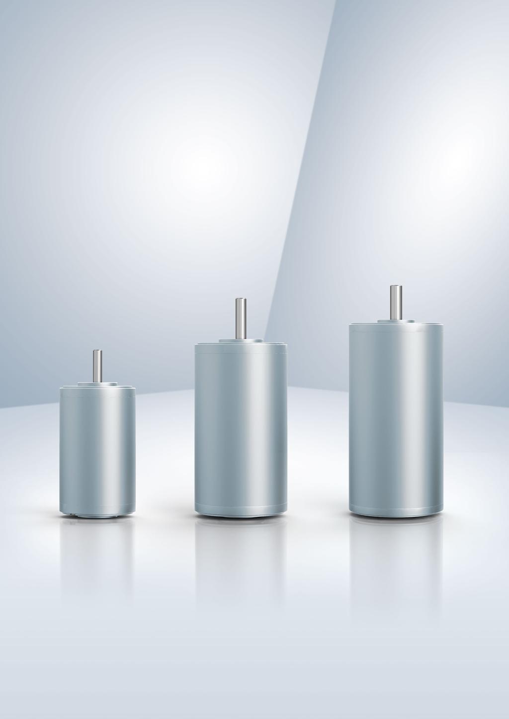
Brushed internal rotor motors BCI series. Drive solutions Industrial drive engineering
|
|
|
- Laurel May
- 6 years ago
- Views:
Transcription

1 Brushed internal rotor motors BCI series Drive solutions Industrial drive engineering
2 Modular drive systems. Motors optional with gearhead, encoder and brake. 2
3 Contents. Information About ebm-papst 4 Overview BCI motors 7 BCI motors Information about BCI motors 10 Definitions for BCI motors 12 BCI-42.XX 14 BCI-52.XX 16 BCI-63.XX 18 Gearheads Performax 42 (planetary gearhead) 22 Performax 52 (planetary gearhead) 24 Performax 63 (planetary gearhead) 26 EtaCrown 52 (crown gearhead) 28 EtaCrown 75 (crown gearhead) 30 EtaCrown Plus 42 (crown gearhead) 32 EtaCrown Plus 63 (crown gearhead) 34 Compactline 90 (spur gearhead) 36 Compactline 91 (spur gearhead) 38 Compactline 92 (spur gearhead) 40 Flatline 78 (spur gearhead) 42 Flatline 85 (spur gearhead) 44 Accessories Brakes 48 Magnetic encoder system 50 Optical encoder system 52 Standards and guidelines 54 Operating factor, lifetime, efficiency 56 ebm-papst around the world 59 3
4 About ebm-papst. As a leader in technologies for ventilation and drive engineering, ebm-papst is in demand as an engineering partner in many sectors. With over 15,000 different products, we provide the right solution for just about any challenge. Our fans and drives are reliable, quiet and energy-efficient. Six reasons that make us the ideal partner: Our systems expertise. You want the best solution for every project. The interrelationships between ventilation and drive engineering must thus be considered as a whole. And that s what we do with motor technology that sets standards, sophisticated electronics and aerodynamic designs all from a single source and perfectly matched. These system solutions release unique synergies worldwide. And in particular they relieve you of a lot of work, so that you can concentrate on your core competency. Proximity to our customers. The ebm-papst Group has 49 sales and 25 production sites worldwide. This means you always have a local contact who speaks your language and knows your market. Our standard of quality. Of course you can rely on the highest standards of quality with our products. Our quality management is uncompromising, at every step in every process. This is underscored by our certification according to international standards, including DIN EN ISO 9001, ISO/TS and DIN EN ISO The ebm-papst spirit of invention. In addition to our wide range of products, we are always able to develop customized solutions for you. A diversified team of 600 engineers and technicians works at our three locations in Germany: Mulfingen, Landshut and St. Georgen. Contact us to discuss your next project. Our lead in technology. As pioneer and trail-blazer for developing highly efficient EC technology, we are way ahead of other motor manufacturers. Almost our entire product range is also available with GreenTech EC technology. The list of benefits is long: higher efficiency, maintenance-free, longer service life, sound reduction, intelligent control characteristics and incomparable energy efficiency with savings of up to 80% compared to conventional AC technology. Let our technology be your competitive advantage as you lead in your industry. Our sustainable approach. Assuming responsibility for the environment, for our employees and for society is an integral part of our corporate philosophy. We develop products with an eye to maximum environmental compatibility, in particular resource-preserving production methods. We promote environmental awareness among our young staff and are actively involved in sporting, cultural activities and education. That s what makes us a leading company and an ideal partner for you. 4

5 Our success story to becoming market leader and technological innovator Elektrobau Mulfingen GmbH & Co. KG founded by Gerhard Sturm and Heinz Ziehl Development of the first compact fan in the field of EC-/DC-technology The ebm-papst success story started to take off with the release of the new 68 motor The first foreign subsidiary was founded in Sweden Gerhard Sturm receives the German Cross of Merit The sixty millionth external rotor fan was produced Acquisition of PAPST Motoren GmbH in St. Georgen Purchase of the Landshut plant (mvl) Change of name to ebm-papst Introduction of the gearhead EtaCrown GreenTech our symbol for energy-efficiency and resource conservation Introduction of a new generation of control electronics (K4) for BLDC motors ebm-papst acquires the gear specialist, Zeitlauf, and wins the German Sustainability Award Launch of the BLDC intenal rotor motor, ECI Introduction of the overload-capable planetary gear Optimax Expansion of the electronic production plant, St. Georgen Hagenmoos. 5
6 6
7 Overview of BCI motors. Brushed internal rotor motors BCI BCI (page 14) BCI (page 14) BCI (page 16) BCI (page 16) BCI (page 18) BCI (page 18) U N V DC M N mnm P W n N rpm 3,900 3,600 4,200 3,500 3,600 3,600 l mm d mm Gearheads (page 22) Performax 42 (planetary gearhead) (page 22) Performax 52 (planetary gearhead) (page 24) Performax 63 (planetary gearhead) (page 26) EtaCrown 52 (crown gearhead) (page 28) EtaCrown 75 (crown gearhead) (page 30) EtaCrown Plus 42 (crown gearhead) (page 32) EtaCrown Plus 63 (crown gearhead) (page 34) Compactline 90 (spur gearhead) (page 36) Compactline 91 (spur gearhead) (page 38) Compactline 92 (spur gearhead) (page 40) Flatline 78 (spur gearhead) (page 42) Flatline 85 (spur gearhead) (page 44) Encoder systems (page 50) PMG 2-2/2-12 (magnetical) HEDS 5500/512 (optical, incremental) Brakes (page 48) BFK (spring-applied) Subject to alterations Standard type Preferred type: ready to ship in 48 hours With our preferred type products, we offer a selection of motors and gear motors which are available and ready to ship within 48 hours. Preferred type products can be ordered with a maximum order quantity of 20 products per order. With standard type products, we refer to a wide range of motors and gear motors which can be ordered using the stated order numbers with standard delivery times. Further products for your project requirements are available on request. These products are generally available but cannot be ordered by means of an allocated material number. We reserve the right to make changes to the necessary order numbers after technical and economic evaluation of the requirement. 7
8 8

9 BCI motors. BCI-42.XX 14 BCI-52.XX 16 BCI-63.XX 18 9


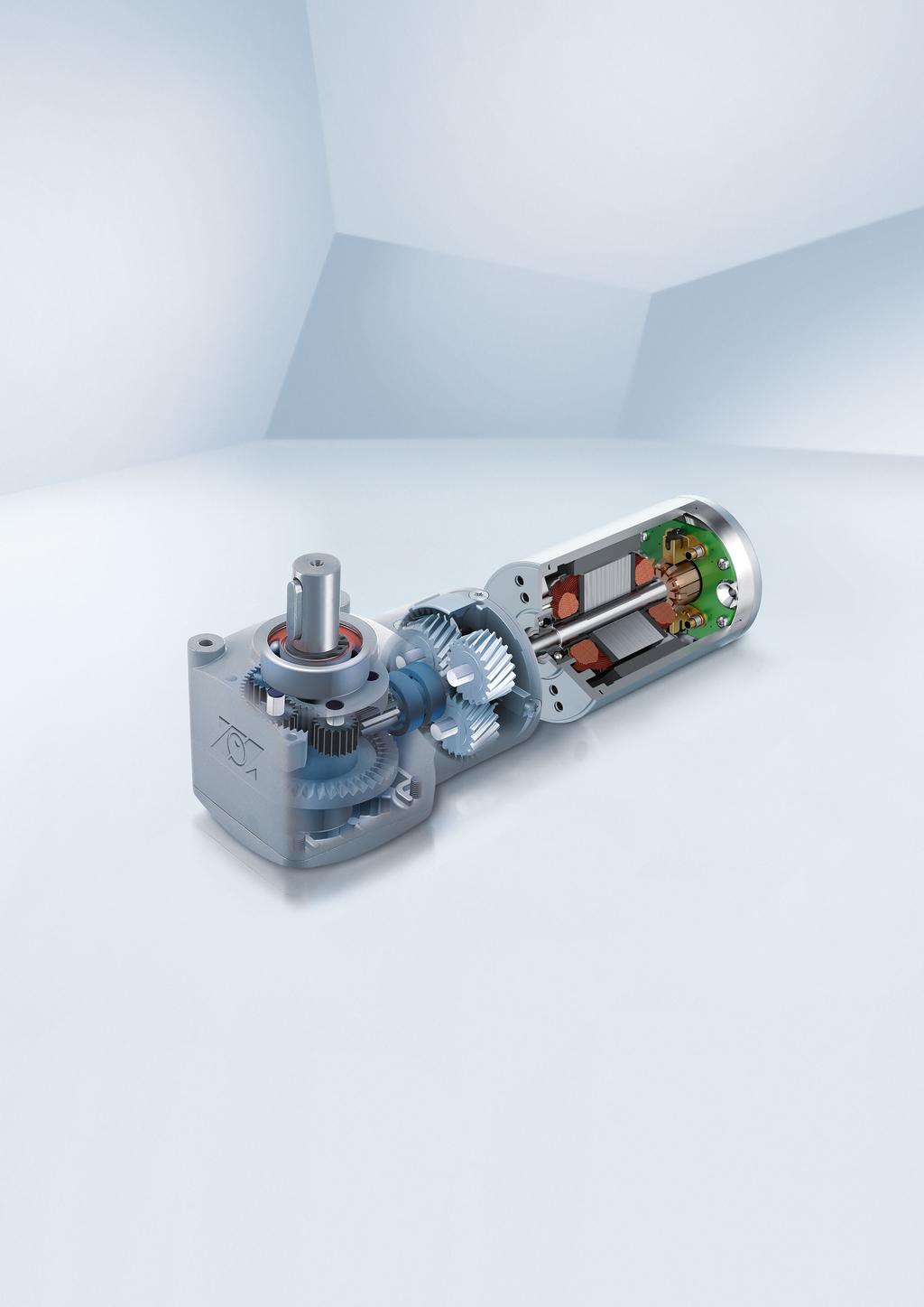
10 Information about BCI motors. Key figures DC motor with permanent magnets Power range between 13 and 93 watts High power density realized in a compact design High overload capacity Highly efficient Mechanical commutation through a multi-piece collector Customer-specific winding layout Winding insulation as per insulation class B Protection class IP 40, optionally higher Approvals Support with the accreditation of products in different economic areas and markets As an experienced and competent partner we would be happy to support you Possible approvals include CE, CCC, UL, CSA, EAC or other certification marks. Various motor types which can be combined with planetary, crown and spur gearheads Optional encoder and brake modules Carbon brush Collector Magnet Winding 10
11 The data in this catalog contain product specifications, but are not a guarantee of particular properties. All information is based on the measuring conditions mentioned below. Operation of motors using reference electronics at an ambient temperature of max. 40 C when attached (thermally conductive) to a free-standing steel plate of the following size: Steel plate 105 x 105 x 10 mm The nominal operating point is the basis for the electromagnetic design of the motor from the point of view of the maximum possible continuous output of the motor and is specified by the nominal values described here. The values mentioned are typical values for the design in question and are also subject to the tolerances included in the specifications or drawings. Unless otherwise stated, the supplements and safety notes contained in the relevant operating and assembly instructions must be kept at all times. Subject to availability and technical alterations. Nominal voltage U BN [V DC] The DC voltage that is applied to the DC motor as a supply voltage. All nominal values listed in the technical tables of the individual motors refer to this voltage. Motor applications are, however, not restricted to this voltage. Changing the voltage results in a parallel shift of the motor curve. The lower voltage limit is defined by the commutator contact resistance and the start-up behavior of the motor. The lower limit results from the mechanical ceiling speed of the motor. In every case, when selecting the voltage and defining the operating point, thermal overload of the motor in continuous operation or the selected operating cycle must be avoided. The ripple of the supply voltage should not exceed 3-5% in normal operation, as higher ripple means poorer efficiency and control quality and corresponding speed fluctuations. Nominal speed n N [rpm] The speed at which the motor can be operated for long periods at an ambient temperature of 40 C and with output of the nominal torque in a thermally conductive installation. It is an operating point at the max. motor curve. Nominal torque M N [mnm] The torque that the motor can output for long periods at an ambient temperature at 40 C and with output of the nominal torque in a thermally conductive installation. Speed n [min -1 ] Speed at no-load operation M N M Max 90 nominal operating point 80 1, ,5 20 Continuous Short-time 10 operation operation Torque M [mnm] The illustrated curves are idealized representations based on the figures in the tables. Nominal current I N [A] The current that is drawn from the system supply when the motor delivers nominal torque at nominal speed. P N = M N N = Nominal output power P N [W] π 30 n N M N = ca. 0.1 M N n N The product of the nominal torque and nominal angular velocity. When calculating this value, the tolerances of the individual values contained in the specification data sheets must be considered. In the electromagnetic design of the motors, the nominal operating point is defined with consideration of the fact that the nominal output corresponds approximately to the maximum permitted longterm output power of the motor. Current I [A] Efficiency [%] 11
12 Definitions for BCI motors. Rated efficiency η N [%] Indicates the ratio in % of the mechanical output power to the absorbed electrical output relative to the nominal operating point. Typically, the nominal operating point is close to the optimum efficiency. Speed at no-load operation n L [rpm] The speed that takes effect at the nominal voltage and with unloaded motor. For the DC motor, it is proportional to the applied supply voltage. The theoretical possible speed at no-load operation can, in some cases, be limited by the mechanical ceiling speed. Start-up torque M A [mnm] The torque that the motor can output for short periods at speed "0" rpm and current draw in the amount of the start-up current at startup or as holding torque. Start-up current I A [A] The current drawn from the DC voltage source as the supply current if the motor outputs "0" rpm as the start-up torque. If the power supply used has a design that is too weak, it may not be possible to reach this point. In this case, the maximum possible start-up torque is limited by the power pack. Induced current U imax [V/1,000 rpm] The value of the induced current in the motor per 1,000 rpm. It is a measure for the electromagnetic design of the motor. In no-load operation, the induced current is approximately equal to the applied supply voltage (minus the voltage loss via the ohmic resistance of the winding). Torque-forming current no longer flows; as a result, no more torque can be output to the shaft in no-load operation. The values specified in the technical data are based on an ambient temperature of 25 C. Connection resistance R v [Ohm] The resistance measure at both connection lines of the motor at 20 C. Thus it is the total resistance composed of the line resistance, brush-collector contact resistance and the actual winding resistance. Connection inductance L V [mh] The average inductance measured at 20 C between the two connection lines of the motor with a sinusoidal measuring frequency of 1 khz. Rotor moment of inertia J R [kgm 2 x10⁻⁶ ] The mass moment of inertia of the wound rotor and thus a defining variable for the dynamic properties of the motor. Thermal resistance R th [K/W] A substitutional resistance at normal rating that results from the difference between the winding temperature and the ambient temperature in relation to the overall power loss. Protection class Information on the protection class complies with the valid Standard EN It describes protection against foreign particles (Point 1) and water (Point 2). Permissible ambient temperature range T U [ C] Defines the minimum and maximum permissible ambient temperature to which the mentioned performance values apply when the motor is in operation. Other ambient temperatures are possible but should be given special consideration as e. g. higher ambient temperatures result in a reduction of output power. Here, it must be ensured that the permitted winding temperature in the motor (e.g. for insulation material class B = 130 C, to EN ) is not exceeded. The following formula can be used to provide a rough estimate of the reduced torque permitted at a higher temperature: T winding. max. - T amb. M red = M N T winding. max. - T N M red = value for the reduced torque to be measured T winding max. = max. permitted winding temperature defined by the ISO class T amb. = value for the elevated ambient temperature T N = reference temperature for specifying the nominal data Please contact the manufacturer if the drives are operated or stored under non standard environmental conditions. 12

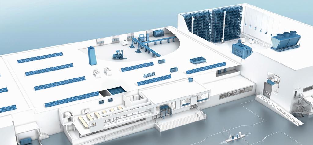

13 Factory building Medical technology Railway technology 13

14 BCI motor. BCI-42.XX Direct current motor with permanent magnets made of ceramic bound ferrite Mechanical commutation through 8-piece collector Closed steel motor housing with die-cast zinc bearing flanges Operation in both directions of rotation Service life 3,000 h for continuous operation (S1) Insulation class B Protection class IP 40, optionally higher Nominal data Type BCI A00 BCI B00 BCI A00 BCI B00 Nominal voltage (U BN ) V DC Nominal speed (n N )* rpm 3,300 3,300 3,100 3,100 Nominal torque (M N )* mnm Nominal current (I BN )* A Nominal output power (P N )* W Rated efficiency, approx. (ηn) % Free-running speed (n L ) rpm 4,000 3,900 3,850 3,600 Free-running current (I BL ) A Starting torque (M A ) mnm Starting current (I A ) A Induced voltage (U imax ) V/1,000 rpm Connection resistance (R V ) Ohm Connection inductance (L V ) mh Rotor moment of inertia (J R ) kgm 2 x Heat resistance (R th ) K/W Protection class** IP 40 Permissible ambient temperature range (T U ) C Motor mass (m) kg Order No. on request on request subject to alterations * at T U max. 40 C Preferred type: ready to ship in 48 hours ** Classification of protection class refers to installed state with sealing on the flange side Characteristic curve BCI-42.25, 24 V (at 25 C) BCI-42.40, 24 V (at 25 C) M N M Max M N M Max , , Speed n [min -1 ] ,5 Current I [A] Efficiency [%] Speed n [min -1 ] ,5 Current I [A] Efficiency [%] 0 Continuous Short-time operation operation Continuous Short-time operation operation Torque M [mnm] Torque M [mnm] 1) Nominal data, see table 1) Nominal data, see table 14
15 Technical drawing Image standard type / All dimensions in mm Shaft dimensions ØD (A-side) L2 (A-side) ØD (B-side) L (B-side) Standard type 5 g mm Preferred type 5 g mm 5 g5 15 mm Type L1 BCI ± 0.5 BCI ± 0.5 * Blind holes for thread-forming screws according to DIN 7500 Fradial L1 Faxial F axial 30 N F radial 60 N L1 20 mm Permissible shaft load at nominal speed and life expectancy L 10 of 3,000 h (at T U 40 C). Electrical connection Connection cable Color Function red Power supply (+) Cable length 300 ± 30 from motor black GND (-) Cable end 7 ± 2 stripped and tin-coated Change of the rotating direction is possible by polarity reversal of the wires Modular construction kit Brake system Spring-applied braking BFK (page 48) Basic motor Planetary gearhead Performax 42 (page 22) Encoder system Magnetic encoder system PMG 2-X (page 50) Optical incremental encoder HEDS 5500 / PWB AE30 (page 52) Crown gearhead EtaCrown 52 (page 28) EtaCrown Plus 42 (page 32) Spur gearheads Compactline 90 (page 36) For motor-gearbox combinations, depending on the choice of the single components, the maximum allowable torque (gearbox) can be exceeded or respectively not reached. 15

16 BCI motor. BCI-52.XX Direct current motor with permanent magnets made of ceramic bound ferrite Mechanical commutation through 12-piece collector Closed steel motor housing with die-cast zinc bearing flanges Operation in both directions of rotation Service life 3,000 h for continuous operation (S1) Insulation class B Protection class IP 40, optionally higher Nominal data Type BCI A00 BCI B00 BCI A00 BCI B00 Nominal voltage (U BN ) V DC Nominal speed (n N )* rpm 3,600 3,600 3,150 3,150 Nominal torque (M N )* mnm Nominal current (I BN )* A Nominal output power (P N )* W Rated efficiency, approx. (ηn) % Free-running speed (n L ) rpm 4,200 4,200 3,600 3,600 Free-running current (I BL ) A Starting torque (M A ) mnm ,100 Starting current (I A ) A Induced voltage (U imax ) V/1,000 rpm Connection resistance (R V ) Ohm Connection inductance (L V ) mh Rotor moment of inertia (J R ) kgm 2 x Heat resistance (R th ) K/W Protection class** IP 40 Permissible ambient temperature range (T U ) C Motor mass (m) kg Order no. on request on request subject to alterations * at T U max. 40 C Preferred type: ready to ship in 48 hours ** Classification of protection class refers to installed state with sealing on the flange side Characteristic curve BCI A00, 24 V (at 25 C) BCI A00, 24 V (at 25 C) M N M Max M N M Max Speed n [min -1 ] Current I [A] Efficiency [%] Speed n [min -1 ] Current I [A] Efficiency [%] 0 Continuous Short-time operation operation Continuous Short-time operation operation Torque M [mnm] Torque M [mnm] 1) Nominal data, see table 1) Nominal data, see table 16

17 Technical drawing Image standard type / All dimensions in mm Shaft dimensions ØD (A-side) L2 (A-side) ØD (B-side) L (B-side) Standard type 6 g mm Preferred type 6 g mm 6 g5 15 mm Type L1 BCI ± 0.5 BCI ± 0.5 * Blind holes for thread-forming screws according to DIN 7500 Fradial L1 Faxial F axial 90 N F radial 130 N L1 20 mm Permissible shaft load at nominal speed and life expectancy L 10 of 3,000 h (at T U 40 C). Electrical connection Connection cable Color Function red Power supply (+) Cable length 300 ± 30 from motor black GND (-) Cable end 7 ± 2 stripped and tin-coated Change of the rotating direction is possible by polarity reversal of the wires Modular construction kit Brake system Basic motor Spring-applied braking BFK (page 48) Planetary gearhead Performax 52 (page 24) Encoder system Magnetic encoder system PMG 2-X (page 50) Optical incremental encoder HEDS 5500 / PWB AE30 (page 52) For motor-gearbox combinations, depending on the choice of the single components, the maximum allowable torque (gearbox) can be exceeded or respectively not reached. 17

18 BCI motor. BCI-63.XX Direct current motor with permanent magnets made of ceramic bound ferrite Mechanical commutation through 12-piece collector Closed steel motor housing with die-cast zinc bearing flanges Operation in both directions of rotation Service life 3,000 h for continuous operation (S1) Insulation class B Protection class IP 40, optionally higher Nominal data Type BCI A00 BCI B00 BCI A00 BCI B00 Nominal voltage (U BN ) V DC Nominal speed (n N )* rpm 3,150 3,150 3,000 3,000 Nominal torque (M N )* mnm Nominal current (I BN )* A Nominal output power (P N )* W Rated efficiency, approx. (ηn) % Free-running speed (n L ) min Free-running current (I BL ) A Starting torque (M A ) mnm 840 1,100 1,900 2,550 Starting current (I A ) A Induced voltage (U imax ) V/1,000 rpm Connection resistance (R V ) Ohm Connection inductance (L V ) mh Rotor moment of inertia (J R ) kgm 2 x Heat resistance (R th ) K/W Protection class** IP 40 Permissible ambient temperature range (T U ) C Motor mass (m) kg Order no. on request on request subject to alterations * at T U max. 40 C Preferred type: ready to ship in 48 hours ** Classification of protection class refers to installed state with sealing on the flange side Characteristic curve BCI A00, 24 V (at 25 C) BCI A00, 24 V (at 25 C) M N M Max 90 M N M Max Speed n [min -1 ] Current I [A] Efficiency [%] Speed n [min -1 ] Current I [A] Efficiency [%] 0 Continuous Short-time operation operation Continuous Short-time operation operation Torque M [mnm] Torque M [mnm] 1) Nominal data, see table 1) Nominal data, see table 18
19 Technical drawing Image standard type / All dimensions in mm Shaft dimensions ØD (A-side) L2 (A-side) ØD (B-side) L (B-side) Type L1 Standard type 8 g5 25,0 mm BCI ± 0.5 Preferred type 8 g5 20,2 mm 8 g5 15 mm BCI ± 0.5 * Blind holes for thread-forming screws according to DIN 7500 Fradial L1 Faxial F axial 150 N F radial 150 N L1 20 mm Permissible shaft load at nominal speed and life expectancy L 10 of 3,000 h (at T U 40 C). Electrical connection Connection cable Color Function red Power supply (+) Cable length 300 ± 30 from motor black GND (-) Cable end 7 ± 2 stripped and tin-coated Change of the rotating direction is possible by polarity reversal of the wires Modular construction kit Brake system Spring-applied braking BFK (page 48) Basic motor Planetary gearhead Performax 63 (page 26) Encoder system Magnetic encoder system PMG 2-X (page 50) Optical incremental encoder HEDS 5500 / PWB AE30 (page 52) Crown gearhead EtaCrown 75 (page 30) EtaCrown Plus 63 (page 34) Spur gearheads Compactline 90 (page 36) Compactline 91 (page 38) Flatline 85 (page 44) For motor-gearbox combinations, depending on the choice of the single components, the maximum allowable torque (gearbox) can be exceeded or respectively not reached. 19


20 20
 22 Performax 52 (planetary gearhead) 24 Performax 63 (planetary gearhead) 26 EtaCrown 52 (crown gearhead) 28 EtaCrown 75 (crown gearhead) 30 EtaCrown Plus 42 (crown")
21 Gearheads. Performax 42 (planetary gearhead) 22 Performax 52 (planetary gearhead) 24 Performax 63 (planetary gearhead) 26 EtaCrown 52 (crown gearhead) 28 EtaCrown 75 (crown gearhead) 30 EtaCrown Plus 42 (crown gearhead) 32 EtaCrown Plus 63 (crown gearhead) 34 Compactline 90 (spur gearhead) 36 Compactline 91 (spur gearhead) 38 Compactline 92 (spur gearhead) 40 Flatline 78 (spur gearhead) 42 Flatline 85 (spur gearhead) 44 Operating factor, lifetime, efficiency 56 21
22 Planetary gearheads. Performax 42 High power density from compact dimensions Very quiet running due to helical teeth in the first gear stage Planetary wheels made of plastic with optimized sliding properties in the first stage ensure smooth operation Large effective diameter thanks to radial screw connection Economical setup due to use of many individual parts which are readily available on the market Image of 2-stage gearhead Nominal data Gearheads Performax 42.1 Performax 42.2 Reduction ratio No. of stages 1 2 Efficiency Max. input speed (n 1 ) rpm 6,000 6,000 Rated output torque (M ab ) Nm Short-term torque (M max ) Nm Gear play Permissible operating temperature (T U ) C Operating mode S1 S1 Protection class IP 50 IP 50 Weight (m) kg Shaft load radial/axial N 250/ /150 Service life h 5,000 5,000 Lubrication Maintenance-free grease lubrication for life Installation position any Subject to alterations Preferred type: ready to ship in 48 hours 22
23 Technical drawing Image of 1-stage gearhead / 2-stage design completely cylindrical / All dimensions in mm Fradial L1 Faxial F axial F radial L1 150 N 250 N 12.5 mm Permissible shaft load at nominal speed and life expectancy L 10 (nominal operation) and operating factor CB = 1 (see page 56) of 5,000 h (at T U 40 C). Length of the possible motor/gearhead combinations Motor/gearhead L - 1-stage L - 2-stage BCI P42 mm BCI P42 mm Subject to alterations 23

24 Planetary gearheads. Performax 52 High power density from compact dimensions Very quiet running due to helical teeth in the first gear stage Planetary wheels made of plastic with optimized sliding properties in the first stage ensure smooth operation Large effective diameter thanks to radial screw connection Economical setup due to use of many individual parts which are readily available on the market Image of 2-stage gearhead Nominal data Gearheads Performax 52.1 Performax 52.2 Reduction ratio No. of stages 1 2 Efficiency Max. input speed (n 1 ) rpm 6,000 6,000 Rated output torque (M ab ) Nm Short-term torque (M max ) Nm Gear play Permissible operating temperature (T U ) C Operating mode S1 S1 Protection class IP 50 IP 50 Weight (m) kg Shaft load radial/axial N 350/ /500 Service life h 5,000 5,000 Lubrication Maintenance-free grease lubrication for life Installation position any Subject to alterations Preferred type: ready to ship in 48 hours 24
25 Technical drawing Image of 1-stage gearhead / 2-stage design completely cylindrical / All dimensions in mm Fradial L1 Faxial F axial F radial L1 500 N 350 N 12.5 mm Permissible shaft load at nominal speed and life expectancy L 10 (nominal operation) and operating factor CB = 1 (see page 56) of 5,000 h (at T U 40 C). Length of the possible motor/gearhead combinations Motor/gearhead L - 1-stage L - 2-stage BCI P52 mm BCI P52 mm Subject to alterations 25

26 Planetary gearheads. Performax 63 High power density from compact dimensions Very quiet running due to helical teeth in the first gear stage Planetary wheels made of plastic with optimized sliding properties in the first stage ensure smooth operation Large effective diameter thanks to radial screw connection Economical setup due to use of many individual parts which are readily available on the market Image of 1-stage gearhead Nominal data Gearheads Performax 63.1 Performax 63.2 Reduction ratio No. of stages 1 2 Efficiency Max. input speed (n 1 ) rpm 6,000 6,000 Rated output torque (M ab ) Nm Short-term torque (M max ) Nm Gear play Permissible operating temperature (T U ) C Operating mode S1 S1 Protection class IP 50 IP 50 Weight (m) kg Shaft load radial/axial N 350/ /500 Service life h 5,000 5,000 Lubrication Maintenance-free grease lubrication for life Installation position any Subject to alterations Preferred type: ready to ship in 48 hours 26
27 Technical drawing Image of 1-stage gearhead / 2-stage design completely cylindrical / All dimensions in mm Fradial L1 Faxial F axial F radial L1 500 N 350 N 19 mm Permissible shaft load at nominal speed and life expectancy L 10 (nominal operation) and operating factor CB = 1 (see page 56) of 5,000 h (at T U 40 C). Length of the possible motor/gearhead combinations Motor/gearhead L - 1-stage L - 2-stage BCI P63 mm BCI P63 mm Subject to alterations 27
28 Crown gearheads. EtaCrown 52 Maximum safety in design and operation, as well as optimal vandalism protection; no automatic lock due to high efficiency of the crow wheel technology Space-saving installation due to zero offset axle and symmetrical structure Flexible application possibilities with various optional shaft outlets and available shaft geometries Wide reduction range by means of upstream/downstream planetary stage High radial loads due to double ball bearing in the output shaft Image of 2-stage gearhead Nominal data Gearheads EtaCrown 52.1 EtaCrown 52.2 Reduction ratio No. of stages 1 2 Efficiency Max. input speed (n 1 ) rpm 6,000 6,000 Rated output torque (M ab ) Nm Short-term torque (M max ) Nm Gear play Permissible operating temperature (T U ) C Operating mode S1 S1 Protection class IP 50 IP 50 Weight (m) kg Shaft load radial/axial N 300/ / / / / / /150 Service life h 5,000 5,000 Lubrication Maintenance-free grease lubrication for life Installation position any Subject to alterations Preferred type: ready to ship in 48 hours 28
29 Technical drawing Image of 1-stage gearhead with left shaft end (W05)/All dimensions in mm Fradial L1 Faxial F axial F radial L1 150 N see table 12.5 mm Permissible shaft load at nominal speed and life expectancy L 10 (nominal operation) and operating factor CB = 1 (see page 56) of 5,000 h (at T U 40 C). Shaft end, left (W06) Shaft end, both sides (W07) Length of the possible motor/gearhead combinations Motor/gearhead L - 1-stage L - 2-stage BCI E52 mm BCI E52 mm Subject to alterations 29

30 Crown gearheads. EtaCrown 75 Maximum safety in design and operation, as well as optimal vandalism protection; no automatic lock due to high efficiency of the crow wheel technology Space-saving installation due to zero offset axle and symmetrical structure Flexible application possibilities with various optional shaft outlets and available shaft geometries Wide reduction range by means of upstream/downstream planetary stage High radial loads due to double ball bearing in the output shaft Image of 2-stage gearhead Nominal data Gearheads EtaCrown 75.1 EtaCrown 75.2 Reduction ratio No. of stages 1 2 Efficiency Max. input speed (n 1 ) rpm 6,000 6,000 Rated output torque (M ab ) Nm Short-term torque (M max ) Nm Gear play Permissible operating temperature (T U ) C Operating mode S1 S1 Protection class IP 50 IP 50 Weight (m) kg Shaft load radial/axial N 150/ / / / / / /500 Service life h 5,000 5,000 Lubrication Maintenance-free grease lubrication for life Installation position any Subject to alterations Preferred type: ready to ship in 48 hours 30
31 Technical drawing Image of 1-stage gearhead with left shaft end (W05)/All dimensions in mm Fradial L1 Faxial F axial F radial L1 500 N see table 15 mm Permissible shaft load at nominal speed and life expectancy L 10 (nominal operation) and operating factor CB = 1 (see page 56) of 5,000 h (at T U 40 C). Shaft end, left (W06) Shaft end, both sides (W07) Hollow shaft (W08) Hollow shaft Ø 10 mm Length of the possible motor/gearhead combinations Motor/gearhead L - 1-stage L - 2-stage BCI E75 mm BCI E75 mm Subject to alterations 31
32 Crown gearheads. EtaCrown Plus 42 Compact design due to combination of the crown wheel and planetary stage in one housing No automatic lock due to high efficiency of the crow wheel technology High torques by using 5 straight toothed planetary gears made of case-hardened sintered steel in the integrated planetary gear stage Wide reduction range thanks to possibility of an upstream planetary stage Improved running smoothness thanks to the optimized design of the crown wheel stage when using an upstream helical planetary gear stage made of plastic with optimized sliding properties Image of 3-stage gearhead Nominal data Gearheads EtaCrown Plus 42.3 Reduction ratio No. of stages 3 Efficiency 0.73 Max. input speed (n 1 ) rpm 6,000 Rated output torque (M ab ) Nm Short-term torque (M max ) Nm Gear play Permissible operating temperature (T U ) C Operating mode S1 Protection class IP 50 Weight (m) kg 0.45 Shaft load radial/axial N 300/200 Service life h 5,000 Lubrication Maintenance-free grease lubrication for life Installation position any Subject to alterations Preferred type: ready to ship in 48 hours 32
33 Technical drawing Image of 3-stage gearhead/all dimensions in mm Fradial L1 Faxial F axial F radial L1 200 N 300 N 10 mm Permissible shaft load at nominal speed and life expectancy L 10 (nominal operation) and operating factor CB = 1 (see page 56) of 5,000 h (at T U 40 C). Length of the possible motor/gearhead combinations Motor/gearhead L - 3-stage BCI EP42 mm 150 BCI EP42 mm 165 Subject to alterations 33

34 Crown gearheads. EtaCrown Plus 63 Compact design due to combination of the crown wheel and planetary stage in one housing No automatic lock due to high efficiency of the crow wheel technology High torques by using 5 straight toothed planetary gears made of case-hardened sintered steel in the integrated planetary gear stage Wide reduction range thanks to possibility of an upstream planetary stage Improved running smoothness thanks to the optimized design of the crown wheel stage when using an upstream helical planetary gear stage made of plastic with optimized sliding properties Image of 3-stage gearhead Nominal data Gearheads EtaCrown Plus 63.3 Reduction ratio No. of stages 3 Efficiency 0.73 Max. input speed (n 1 ) rpm 6,000 Rated output torque (M ab ) Nm Short-term torque (M max ) Nm Gear play Permissible operating temperature (T U ) C Operating mode S1 Protection class IP 50 Weight (m) kg 1.00 Shaft load radial/axial N 600/300 Service life h 5,000 Lubrication Maintenance-free grease lubrication for life Installation position any Subject to alterations Preferred type: ready to ship in 48 hours 34
35 Technical drawing Image of 3-stage gearhead/all dimensions in mm Fradial L1 Faxial F axial F radial L1 300 N 600 N 15 mm Permissible shaft load at nominal speed and life expectancy L 10 (nominal operation) and operating factor CB = 1 (see page 56) of 5,000 h (at T U 40 C). Length of the possible motor/gearhead combinations Motor/gearhead L - 3-stage BCI EP63 mm 211 BCI EP63 mm 241 Subject to alterations 35
36 Spur gearheads. Compactline 90 Minimum space requirement due to compact design High power density High torques from the smallest possible dimensions Very smooth operation thanks to optimized gear geometries and materials Maintenance-free over entire service life Nominal data Gearheads Compactline 90.2 Compactline 90.3 Compactline 90.4 Reduction ratio No. of stages Efficiency Max. input speed (n 1 ) rpm 4,000 4,000 4,000 Rated output torque (M ab ) Nm Short-term torque (M max ) Nm Gear play Permissible operating temperature (T U ) C Operating mode S1 S1 S1 Protection class* IP 50 IP 50 IP 50 Weight (m) kg Shaft load radial/axial N 120/40 120/40 120/40 Service life h 5,000 5,000 5,000 Lubrication Maintenance-free grease lubrication for life Installation position any Subject to alterations * Classification of protection class refers to installed state with sealing on the flange side 36
37 Technical drawing All dimensions in mm Fradial L1 Faxial F axial F radial L1 40 N 120 N 17 mm Permissible shaft load at nominal speed and a life expectancy L 10 (nominal operation) and operating factor CB = 1 (see page 56) of 5,000 h (at T U 40 C). Length of the possible motor/gearhead combinations Motor/gearhead L BCI C90 mm 111 BCI C90 mm 126 Subject to alterations 37

38 Spur gearheads. Compactline 91 Minimum space requirement due to compact design High power density High torques from the smallest possible dimensions Very smooth operation thanks to optimized gear geometries and materials Maintenance-free over entire service life Nominal data Gearheads Compactline 91.2 Compactline 91.3 Reduction ratio No. of stages 2 3 Efficiency Max. input speed (n 1 ) rpm 4,000 4,000 Rated output torque (M ab ) Nm Short-term torque (M max ) Nm Gear play 0, ,20 0, ,20 Permissible operating temperature (T U ) C Operating mode S1 S1 Protection class* IP 50 IP 50 Weight (m) kg Shaft load radial/axial N 150/50 150/50 Service life h 5,000 5,000 Lubrication Maintenance-free grease lubrication for life Installation position any Subject to alterations * Classification of protection class refers to installed state with sealing on the flange side 38
39 Technical drawing All dimensions in mm Fradial L1 Faxial F axial F radial L1 50 N 150 N 17 mm Permissible shaft load at nominal speed and a life expectancy L 10 (nominal operation) and operating factor CB = 1 (see page 56) of 5,000 h (at T U 40 C). Length of the possible motor/gearhead combinations Motor/gearhead L BCI C91 mm 133 BCI C91 mm 163 Subject to alterations 39

40 Spur gearheads. Compactline 92 Minimum space requirement due to compact design High power density High torques from the smallest possible dimensions Very smooth operation thanks to optimized gear geometries and materials Maintenance-free over entire service life Nominal data Gearheads Compactline 92.2 Compactline 92.3 Reduction ratio No. of stages 2 3 Efficiency Max. input speed (n 1 ) rpm 4,000 4,000 Rated output torque (M ab ) Nm Short-term torque (M max ) Nm Gear play 0, ,20 0, ,20 Permissible operating temperature (T U ) C Operating mode S1 S1 Protection class* IP 50 IP 50 Weight (m) kg Shaft load radial/axial N 150/50 150/50 Service life h 5,000 5,000 Lubrication Maintenance-free grease lubrication for life Installation position any Subject to alterations * Classification of protection class refers to installed state with sealing on the flange side 40
41 Technical drawing All dimensions in mm Fradial L1 Faxial F axial F radial L1 50 N 150 N 17 mm Permissible shaft load at nominal speed and a life expectancy L 10 (nominal operation) and operating factor CB = 1 (see page 56) of 5,000 h (at T U 40 C). Length of the possible motor/gearhead combinations Motor/gearhead L BCI C92 mm 137 BCI C92 mm 167 Subject to alterations 41

42 Spur gearheads. Flatline 78 Optimized installation length due to flat gear design Large reduction range Flexible connection to customer applications due to differ ent available output shafts Use of alternative toothing materials as standard Maintenance-free over entire service life Nominal data Gearheads Flatline 78.3 Flatline Reduction ratio No. of stages 3 4 Efficiency Max. input speed (n 1 ) rpm 4,000 4,000 Rated output torque (M ab ) Nm Short-term torque (M max ) Nm Gear play Permissible operating temperature (T U ) C Operating mode S1 S1 Protection class* IP 50 IP 50 Weight (m) kg Shaft load radial/axial N 300/50 300/50 Service life h 5,000 5,000 Lubrication Maintenance-free grease lubrication for life Installation position any Subject to alterations * Classification of protection class refers to installed state with sealing on the flange side 42
43 Technical drawing All dimensions in mm Fradial L1 Faxial F axial F radial L1 50 N 300 N 17 mm Permissible shaft load at nominal speed and a life expectancy L 10 (nominal operation) and operating factor CB = 1 (see page 56) of 5,000 h (at T U 40 C). Length of the possible motor/gearhead combinations Motor/gearhead L BCI F78 mm 97 Subject to alterations 43
44 Spur gearheads. Flatline 85 Optimized installation length due to flat gear design Large reduction range Flexible connection to customer applications due to differ ent available output shafts Use of alternative toothing materials as standard Maintenance-free over entire service life Nominal data Gearheads Flatline 85.3 Flatline 85.4 Reduction ratio No. of stages 3 4 Efficiency Max. input speed (n 1 ) rpm 4,000 4,000 Rated output torque (M ab ) Nm Short-term torque (M max ) Nm Gear play Permissible operating temperature (T U ) C Operating mode S1 S1 Protection class* IP 50 IP 50 Weight (m) kg Shaft load radial/axial N 150/50 150/50 Service life h 5,000 5,000 Lubrication Maintenance-free grease lubrication for life Installation position any Subject to alterations * Classification of protection class refers to installed state with sealing on the flange side 44
45 Technical drawing All dimensions in mm Fradial L1 Faxial F axial F radial L1 50 N 150 N 17 mm Permissible shaft load at nominal speed and a life expectancy L 10 (nominal operation) and operating factor CB = 1 (see page 56) of 5,000 h (at T U 40 C). Length of the possible motor/gearhead combinations Motor/gearhead L BCI F85 mm 122 BCI F85 mm 152 Subject to alterations 45


46 46
47 Accessories. Brakes 48 Encoder systems 50 47
48 Brakes. Spring-applied braking Single-disk brakes with 2 friction contact surfaces Braking torque effective in powerless state Braking force is eliminated by electromagnetic force Holding brake with emergency stop function Currentless-operated brake with high power density Braking torque applied by spring force Reduced inertia for optimum dynamics Brake system BFK BFK BFK Nominal voltage V DC Nominal power W Braking torque Nm Engagement time ms Disengagement time ms subject to alterations 48
49 Technical drawing All dimensions in mm Brake type Ø D L1 L2 BFK (ECI42.xx) 37 31,3 35,3 BFK (ECI52.xx) 47 31,0 43,0 BFK (ECI63.xx) 56 31,8 43,5 Electrical connection Connection cable Color red black Function Power supply GND 49

50 Magnetic encoder system. Magnetic pulse encoder for direct current motors The encoder is designed for speed recording, control and positioning in conjunction with suitable electronics The encoder is contactor-less and wear-free via 2 Hall sensors. The sensors are positioned around a magnet and generate two rectangular-pulse signals offset by 90 The encoder unit is screwed onto the motor. The electrical connection is via litz wires Electrical protection IP 40 Temperature range -20 C to +80 C Additional resolutions and interfaces possible Encoder system PMG Encoder systems PMG 2-2 PMG 2-12 Pulses per revolution Z 2 12 Nominal voltage V DC Output signal A, B 2 rectangular pulses 90 ± 15, when G03 ± 40 electr. phase offset Pulse ratio Pulse : Pause = 180 : 180 ± 10 Edge steepness, rise 400 ns (U = 12 V DC, RL = 820 Ω) Edge steepness, fall 400 ns (U = 12 V DC, CL = 20 pf) Output load current I load 12 ma (U = 12 V DC) Electronics configuration Open collector output stage with internal pull-up resistors Supply voltage: U B = 4.5 to 24 V DC (protected against polarity reversal) Output amplitude: U low < 0.4 V (at 12 V DC +20 ma) Weight kg 0.03 subject to alterations Signal path PMG A channel A channel 90 electrical phase offset 50
51 Technical drawing All dimensions in mm Electrical connection Connection cable AWG24 Color red yellow black green Function U B 5V... 24V A-channel GND B-channel 51

52 Optical encoder system. Important! Do not use in applications in which failure of the encoder interferes with the safety relevant functions. If in doubt, consult the manufacturer Opto-electronic 2-channel incremental encoder. A corresponding evaluation in an external controller will achieve a resolution of max increments per revolution The encoder is contactor-less and wear-free. The rotary angle resolution is achieved by means of an LED, a metallic encoder disk and a photo-diode array Electrical protection IP 40 Temperature range -40 C to +100 C Additional resolutions and interfaces possible Encoder systems HEDS 5500 No. of pulses Z 512 per revolution (channel A and B) Output signal A, B Reaction frequency [f] 2 rectangular signals (90 phase offset; TTL-compatible) 100 khz Supply voltage [U B ] V + 5 ± 10% Power consumption [I B ] ma type 17 max. 40 Deviation, pulse width [ S ] type 5 (from electrical 90 ) Deviation, phase shift [ P ] type 7 (between channel A and B from electrical 90 ) Index pulse width Electrical connection AMP: or Connector type Berg: with 4825X-000 terminals or Molex: 2695 with 2759 terminals Weight kg 0.02 Subject to alterations Signal processing HEDS 5500 P A channel 90 electrical B channel S1 S2 S3 S4 52
53 Technical drawing Encoder L1 L2 L3 HEDS 18,3 41,1 30 Electrical connection Pin 1 Pin 2 Pin 3 Pin 4 Pin 5 Signal wire Pin Function 1 Ground 2 Approved 3 A 4 UB 5 B 53
54 Standards and Guidelines. Basic information on standards and guidelines for electrical small-power motors and drive systems operated with a DC voltage of max. 75 V DC (nominal voltage): The BCI series described in this catalog are direct current motors in a mechanically commutated design (brush-collector system), which are designed and specified for a nominal voltage of max. 75 V DC. Thus the supply voltage of these drives is within the range of safety extra-low voltage (SELV). On this basis, ebm-papst would like to provide some information intended to help you understand the classification of the motors from the relevant EC Directives and the resulting consequences. The CE label In order to ensure a uniform safety level in the European internal market, the European commission has implemented a new approach for technical harmonization. This has been welcomed by all relevant parties and is visible in many products as a CE label giving proof of agreement with the harmonized provisions. What does CE actually mean? Why don t all products bear the CE label? CE is the abbreviation for Communauté Européenne. The harmonized statutory provisions are a framework directive and belong to the so-called New Approach. This framework directive defines the basic requirements, putting in circulation and operation as well as the applicable conformity assessment process. The manufacturer of a product must now decide which framework directive applies to which product. For electrical small-powered motors the following framework directive can be applied: 1) Machinery Directive 2006/42/EC 2) Low Voltage Directive 2014/35/EU 3) EMC Directive 2014/30/EU Based on these directives, ebm-papst St. Georgen GmbH & Co. KG does not mark the electric motors and drive systems described with the "CE" mark and does not issue an EC Declaration of Conformity. The reason for this is consideration of the relevant EC Directives and the definitions of the terms used, Electric motor and Drive system, by ebm-papst St. Georgen GmbH & Co. KG. Definition of the electric motor An electric motor is a motor without electronics or a motor with integrated electronics of low complexity, such as brush-collector systems, commutation sensors, simple commutation electronics or commutation electronics with simple speed control with a voltage range of <75 V DC (nominal voltage) for use by customers who incorporate them into end devices. According to this definition, electric motors include, for example, the BCI-xx.xx series. Reasons according to the Machinery Directive 2006/42/EC Electric motors are expressly exempt in Art. 1, Par. (2), lit. k) and thus are NOT given the CE mark. Installation instructions to Annex IV and a Declaration of Incorporation to Annex II, Part 1, Section B are available for each motor. The specific technical documents to Art. 13, Par. (1), lit. a) have been created in-house and are archived for the government agencies of the individual countries. Based on this directive, the machine manufacturer is responsible for verifying and ensuring compliance with the basic requirements of the Machinery Directive. Reasons according to the Low Voltage Directive 2014/35/EU Due to the voltage ranges (nominal voltage), the specified electric motors and drive systems do not fall under the application area of the low voltage directive according to Art. 1. Reasons according to the EMC Directive 2014/30/EU Because they are sold exclusively to customers who incorporate them into end devices and not to the end user, the specified electric motors do not fall under the application area of the EMC directive according to the definition of the term in Art. 3, Par. (2), 1: As the small motors are supplied to companies who incorporate them into end devices and not to the end user, ebm-papst has no control over further use of the pre-fabricated components in devices, machines or installations. Therefore, ebm-papst provides express notice that the system manufacturer must provide a suitable EMC circuit when selecting the power supply and must provide for EMC-compliant installation and use in the devices. For more information about EMC-compliant installation and EMC safety measures, refer to resources such as the IEC x series (Installation and Mitigation Guidelines). 54
55 Proper use All motors in this catalog are determined for installation in permanently connected, stationary end devices and machines in the industrial area and must be operated on electricity only when in installed condition! Operation is prohibited until it has been ascertained that this product, along with the machine into which this product is to be installed, complies with the protective requirements of the Machinery Directive. If, when using our motors, market or application-specific product standards apply, compliance with these must be verified and ensured by the device manufacturer. This product is not intended for the end consumer. RoHS European Directive EC No. 2011/65/EU (RoHS) Legally regulated substances As an innovative company and trendsetter in the world of air technology and drive engineering, ebm-papst feels a special obligation towards the environment. Accordingly, under the GreenTech logo, we have implemented a comprehensive concept that extends from the origin to the use of our products. This includes, of course, protecting our environment and using natural resources in a way that conserves them. This applies equally to our manufacturing processes and to our products. When developing our products, we already take into consideration any possible negative consequences they may have for the environment. Our goal is to prevent such environmental impact-even beyond the extent mandated by law-or to reduce it to a minimum, and thus to ensure sustainable development of our products. Thus we ensure that our products are free of materials and substances that are prohibited by law. Of course, all current products have been designed for conformity with European Directive 2011/65/EU (RoHS). All older products that do not yet conform to these directives or parts thereof will be consistently redesigned. Our suppliers are required to provide us only with goods that conform to the directives. Thus we can confirm that basically, all of our products listed in this catalog conform to the above-mentioned directive. We are also available to help with any other questions you may have on both these topics. REACH Directive (EC No. 1907/2006) The EU legal regulation for Registration, Evaluation, Authorization and Restriction of Chemical substances (REACH) entered into force on 1 June This is a chemicals law intended to provide maximum protection to health and the environment. As defined by the REACH directive, ebm-papst is a downstream user. The units you purchase from us are products as defined by REACH and thus do not require registration. However, in our own interest and to ensure a high degree of product safety, we track the implementation of REACH and the resulting requirements as part of our duty to provide information. To comply with the requirements of REACH, we are in contact with all suppliers from whom we obtain chemicals (substances), preparations and components that we use as part of our production process. Within this framework, ebm-papst fulfills the obligations set forth in the REACH regulation. If you have any other questions about the implementation of the REACH directive in our company, please do not hesitate to contact us. 55
56 Operating factor, lifetime, efficiency. Operating factor c B To achieve a uniform lifetime for the gearheads and motors, the necessary torques M must be increased by the respective operating factor c B under the various operating loads so as not to exceed the maximum permissible gearhead torque M 2 max (see table below). Operating modes Load Operating period in h/day 3 h 8 h 24 h 3 h 8 h 24 h even gradual sudden up to 10 switching ops./h over 10 switching ops./h One rotation direction Rotation direction change One rotation direction Rotation direction change One rotation direction Rotation direction change Operating mode It is necessary to define the operating mode under which a gear motor can be operated with certain nominal values in order to avoid overloading the motor and/or the gearhead. The values stated in this catalog refer to S1 operation (continuous operation). This means that the gear motor can be constantly operated with the stated values, but can also have a higher load placed on it for a short time. Please contact us if you require more information about this. Lifetime Lifetime is limited by the various components in the drive. If frequently overloaded, the gearhead components are subjected to more wear than under nominal load. Extreme ambient and operating conditions cause a reduction in the lifetime guaranteed for operation under operating ratio c B = 1. Efficiency η (eta) The efficiency per gear stage is at least 90%. Depending on the tooth configuration and on the manufacturing quality, far better levels of efficiency can also be achieved. The following overall efficiencies were obtained for multi-stage gearheads: Overall efficiency for 1-stage gearhead η = 0.9 for 2-stage gearhead η = = 0.81 for 3-stage gearhead η = = 0.73 for 4-stage gearhead η = = 0.66 for 5-stage gearhead η = =
57 57

58 Region in Germany. Region north Region Middle / East Region Central / West Region South / East Region South / West Region South / East 58
Brushless internal rotor motors ECI series. Drive solutions Industrial drive engineering
 Brushless internal rotor motors ECI series Drive solutions Industrial drive engineering Modular drive systems. Motors with integrated logic and power electronics optional gearhead, encoder and brake. Contents.
Brushless external rotor motor VD/VDC series. Drive solutions Industrial drive engineering
 Brushless external rotor motor VD/VDC series Drive solutions Industrial drive engineering 217-5 Modular drive systems. Motors with integrated logic and power electronics optional gearhead. Contents. Information
Motors- Basic principles. Expertise, performance, innovation
 Motors- Basic principles Expertise, performance, innovation As a leading supplier of ventilation and drive engineering technology, ebm-papst is a highly respected engineering partner in many industries.
Drive Concept for SIMATIC MICRO-DRIVE
 Product Catalog -4 the engineer s choice About ebm-papst ebm-papst is a leader in ventilation and drive engineering technology and a much sought-after engineering partner in many industries. With around,
Product overview Motors and drive systems. Industrial drive technology 2016
 Product overview Motors and drive systems Industrial drive technology 2016 About ebm-papst. As a leader in technologies for ventilation and drive engineering, ebm-papst is in demand as an engineering partner
Product overview Motors and drive systems. Industrial drive technology
 Product overview Motors and drive systems Industrial drive technology About ebm-papst. As technological leader for ventilation and drive engineering, ebm-papst is in demand as an engineering partner in
Product overview Motors and drive systems. Industrial drive technology
 Product overview Motors and drive systems Industrial drive technology About ebm-papst. As technological leader for ventilation and drive engineering, ebm-papst is in demand as an engineering partner in
VARIODRIVE 3-phase external rotor motor. VARIODRIVE technical information VARIODRIVE
 27.05.20 0: Seite Information Antriebstechnik_20_05_27_Finale_EN_:Vorlage VarioDrive C ECI motor 5 AC motors VARIODRIVE -phase external rotor motor Specifications 4 Representatives VARIODRIVE technical
Brushless internal rotor motors with low-backlash planetary gears. Drive solutions Industrial drive engineering
 Brushless internal rotor motors with low-backlash planetary gears Drive solutions Industrial drive engineering 218-6 218-6 2 ECI motors Information about ECI motors Definitions for ECI motors ECI-42.XX-K1
Standard-efficiency gas heating. Innovation is our tradition.
 Standard-efficiency gas heating. Innovation is our tradition. About ebm-papst. As a leader in technologies for ventilation and drive engineering, ebm-papst is in demand as an engineering partner in many
Motors and Gearboxes for Warehouse Logistics. Energy efficient Compact Sustainable
 Motors and Gearboxes for Warehouse Logistics Energy efficient Compact Sustainable High-quality drive unit solutions for warehouse logistics Efficient system solutions from one single source for high performance
3-phase stepping motors
 General Series of Features from Berger Lahr are: Powerful because the optimised internal geometry results in a high power intensity, meaning up to 50 % more torque than standard stepping motors of comparable
DCmind: DC direct-drive brush motors
 DCmind: DC direct-drive brush motors 6 mm - W Silent motor V and V built in EMC filter class B Excellent efficiency ong life IP6 In accordance with U - CE - ROHS regulations Part numbers V V 8 V 9 V Type
4,5 / 27 2,0 / steel, black coated. clockwise, viewed from the front face. ø15,9 ø17-0,052 ø6-0,05. ø3,5 8,1 ±0,3 2, T
 DC-Micromotors Precious Metal Commutation mnm For combination with (overview on page 4-5) Gearheads: 5, 6, 6/7 Encoders: IE 6... 5 Series 3 4 77... SR Nominal voltage Terminal resistance Output power Efficiency
Permanent magnet brakes. Safety from the market leader. PM Line High Torque Line
 Permanent magnet brakes Safety from the market leader PM Line High Torque Line Industrial Drive Systems Die Welt von Kendrion Industrial Drive Systems Kendrion The brake experts As a solution provider,
antriebstechnik Standard Modular System 2011 NEMA connections it s time for tomorrow
 antriebstechnik Standard Modular System 2011 NEMA connections it s time for tomorrow NEMA-Connection for spur and planetary gearheads Flexibility for many applications: The intelligent modular system.
Note: All windings shown are standard configuration. Please contact Motion Technologies for availability of all others
 Table of content Theory 3 1) Brushless Motor MTFL22RBL Series 4 MTFL28BL Series 5 MTFL33BL Series 6 MTFL36RBL Series 7 MTFL42RBL Series 8 MTFL42BL Series 9 MTFL42BLSH Series 10 MTFL57BL Series 11 MTFL57BLSH
Silencer Series Brushless DC Motors
 TYPICAL APPLICATIONS Medical equipment - pumps, blowers and electric scooters and wheelchairs Automatic door and window openers Computer-controlled embroidery machines Scanners Packaging equipment and
Customised drive solutions
 Customised drive solutions Electric motors & systems Drive components Services Introduction 03 Halm quality drive technology Over 50 years of experience in developing electric motors with asynchronous
SELECTING A BRUSH-COMMUTATED DC MOTOR
 SELECTING A BRUSH-COMMUTATED DC MOTOR BASIC PARAMETERS Permanent magnet direct current (DC) motors convert electrical energy into mechanical energy through the interaction of two magnetic fields. One field
Online data sheet DFS60B-S4CA08192 DFS60 INCREMENTAL ENCODERS
 Online data sheet DFS60B-S4C08192 DFS60 B C D E F Illustration may differ Detailed technical data Performance Ordering information Type Part no. DFS60B-S4C08192 1038099 Other models and accessories www.sick.com/dfs60
Quiet-running family of products with the lowest torque pulsation
 Press release Highly dynamic, 3-phase internal rotor motor for industrial applications Quiet-running family of products with the lowest torque pulsation For industrial systems and devices, compact motors
Online data sheet DFS60B-S4EL00800 DFS60 INCREMENTAL ENCODERS
 Online data sheet DFS60B-S4EL00800 DFS60 B C D E F Illustration may differ Detailed technical data Performance Ordering information Type Part no. DFS60B-S4EL00800 1053600 Other models and accessories www.sick.com/dfs60
Stepper motors EMMS-ST
 q/w Worldwide: Superb: Easy: Festo core product range Covers 80% of your automation tasks Always in stock Festo quality at an attractive price Reduces procurement and storing complexity qgenerally ready
DCmind: DC direct-drive brush motors
 DCmind: DC direct-drive brush motors mm - 5 W Silent motor V and V built in EMC filter class B Excellent efficiency ong life IP5 In accordance with U - CE - ROHS regulations Part numbers V V V Type 95
Sensorless Brushless DC-Servomotors
 Sensorless Brushless DC-Servomotors FAULHABER Brushless DC-Servomotors are built for extreme operating conditions. They are precise, have exceptionally long lifetimes and are highly reliable. Outstanding
Motors and Gearboxes for Warehouse Logistics. Energy efficient Compact Sustainable
 Motors and Gearboxes for Warehouse Logistics Energy efficient Compact Sustainable High-quality drive unit solutions for warehouse logistics Efficient system solutions from one single source for high performance
Stepper motors EMMS-ST
 q/w Worldwide: Superb: Easy: Festo core product range Covers 80% of your automation tasks Always in stock Festo quality at an attractive price Reduces procurement and storing complexity qready for dispatch
DC motors. G-motion. CTi Automation - Phone: Fax: Web:
 G-motion No matter which drive solution you imagine, we make your dreams come true. True to our slogan (one stop shopping) we offer you a complete programme of electronic and mechanical drive systems which
Online data sheet DFS60B-S4PC10000 DFS60 INCREMENTAL ENCODERS
 Online data sheet DFS60-S4PC10000 DFS60 DFS60-S4PC10000 DFS60 C D E F H I J K L M N O P Q R S T Ordering information Type Part no. DFS60-S4PC10000 1036721 Other models and accessories www.sick.com/dfs60
Electromagnetic clutch-brake combinations INTORQ
 Electromagnetic clutch-brake combinations INTORQ 14.800 14.867 7.5 120 Nm setting the standard 2 CBC en 5/2005 Contents Clutch-brake combinations Product information 4 Type code 6 Design selection 8 Overview
Table of contents. Three-phase asynchronous motors DA
 be in motion be in motion AC Asynchronous Motors DA 100-280 Table of contents 1. Three-phase asynchronous motor DA 100-280... 3 1.1. General technical data... 3 1.2. Ratings definition for ventilated
Power in new dimensions
 NEW FAULHABER BXT Power in new dimensions WE CREATE MOTION EN Angaben zu Lebensdauer sowie weitere technische Erläuterungen 1 FAULHABER BXT Today, you don't find visionary designs in Hollywood, but rather
Online data sheet. DBS60E-S4EP05000 DBS60 Core INCREMENTAL ENCODERS
 Online data sheet DBS60ES4EP05000 DBS60 Core DBS60ES4EP05000 DBS60 Core A B C D E F Ordering information Type Part no. DBS60ES4EP05000 1071649 Other models and accessories www.sick.com/dbs60_core Illustration
Siemens AG SIMOTICS T-1FW3 Torque Motors. The Powerful Torque Motors. Edition February Brochure. siemens.
 SIMOTICS T-1FW3 Torque Motors The Powerful Torque Motors Brochure Edition February 2017 siemens.com/torquemotors The powerful torque motors Overview The right torque at the right moment this is decisive
ROBATIC ROBA -quick ROBA -takt. Reliable coupling and braking.
 Reliable coupling and braking Equipment Technology Packaging Machinery Conveyors and Materials Handling Equipment Door drives Indexing tables ROBATIC ROBA -quick ROBA -takt www.mayr.de Electromagnetic
Product Data Sheet 8412 N/ The engineer's choice
 The engineer's choice 8412 N/12-252 INDEX 1 General... 3 2 Mechanics... 3 2.1 General... 3 2.2 Connections... 3 3 Operating Data... 4 3.1 Electrical Operating Data... 4 3.2 Electrical Interface - Output...
COMPARING SLOTTED vs. SLOTLESS BRUSHLESS DC MOTORS
 COMPARING SLOTTED vs. SLOTLESS Authored By: Engineering Team Members Pittman Motors Slotless brushless DC motors represent a unique and compelling subset of motors within the larger category of brushless
Series 7000 Torque Sensor for PTO-shafts
 Properties PTO (Power Take-Off) shaft with integrated torque and angle measurement Non-contact measurement system, high robustness Special for PTO shafts 1 ¾ und 1 3/8 Plug & Play solution, no additional
Compact, dynamic and rugged
 Compact, dynamic and rugged Direct drives for harsh operation conditions SIOTICS T Heavy Duty Torque otors Brochure Edition arch 2016 SIOTICS T Heavy Duty Torque otors Overview In many machining processes
Series 7000 Torque Sensor for PTO-shafts
 Properties PTO (Power Take-Off) shaft with integrated torque and angle measurement Non-contact measurement system, high robustness Special for PTO shafts 1 ¾ und 1 3/8 Plug & Play solution, no additional
Lexium integrated drives
 Description ILp for DeviceNet, EtherCAT, Modbus TCP, ILE with brushless DC motor Description ILE comprise control electronics with a fieldbus interface for DeviceNet, EtherCAT, Modbus TCP or and a brushless
Lexium integrated drives
 Description ILp for CANopen, PROFIBUS DP, RS ILE with brushless DC motor Description ILE comprise control electronics with a fieldbus interface for CANopen DS, PROFIBUS DP or RS and a brushless DC motor.
Product Data Sheet 4118 N/ The engineer's choice
 The engineer's choice 4118 N/12-190 INDEX 1 General... 3 2 Mechanics... 3 2.1 General... 3 2.2 Connections... 3 3 Operating Data... 4 3.1 Electrical Operating Data... 4 3.2 Operating Data - Electrical
Steering column and sensor
 Steering column and sensor Type LAB Series 1 x Nominal voltage 12 to 48 volt Output signal digital, analog and direction (option) HE 11874 / 09.2017 2 LAB HE 11874 / 09.2017 Page Content 4 4 5 6 7 7 8
Drive technology for AC and DC
 Drive technology for AC and DC version 2011 The engineer s choice Innovations for the future The right product for every requirement Trendsetters in drive technology Welcome to ebm-papst, the leaders and
SIMOTICS S-1FT7 Servomotors. The Compact Servomotors for High-Performance Motion Control Applications. Motors. Edition April 2017.
 Motors SIMOTICS S-1FT7 Servomotors The Compact Servomotors for High-Performance Motion Control Applications Brochure Edition April 2017 siemens.com/servomotors The Servomotors for High-Performance Applications
EXPERTS IN MOTION CONTROL I N D U S T R I A L P R O D U C T S
 EXPERTS IN MOTION CONTROL I N D U S T R I A L P R O D U C T S COMPANY-WIDE COMMITMENT TO QUALITY At Globe Motors, we re committed to providing customers with products and services that meet or exceed their
Press News. Silent, dynamic and powerful: The new motor series ECI Compact by ebm-papst
 Press News Silent, dynamic and powerful: The new motor series ECI 42.40 Compact by ebm-papst All-inclusive: The turn-key drive solutions The electronically commutated ECI 42.40 Compact, with a nominal
HBI 22. Integrated Three-phase Synchronous Drive
 HBI 22 Integrated Three-phase Synchronous Drive positioning capability up to 9 Watts rated output power with linear hall sensor system with or without parking brake Motor type Dimension L1 L2 HBI 223 125
K4 drive systems Brilliantly versatile. Drive solutions Industrial drive engineering
 K4 drive systems Brilliantly versatile Drive solutions Industrial drive engineering 217-11 About ebm-papst. As technological leader for ventilation and drive engineering, ebm-papst is in demand as an engineering
Installation and Operational Instructions for ROBATIC -clutch Types _.0 and _.0 Sizes 3 7
 Please read these Installation and Operational Instructions carefully and follow them accordingly! Ignoring these Instructions may lead to malfunction or to clutch failure, resulting in damage to other
Elevation Line. Spring-applied single-disc brake and spring-applied double-disc brake for the elevator technology
 Elevation Line Spring-applied single-disc brake and spring-applied double-disc brake for the elevator technology Industrial Drive Systems Die Welt von Kendrion Industrial Drive Systems Kendrion The brake
AC axial fan. blades with special design (K series) with guard grille for full nozzle
 with guard grille for full nozzle") SE6-EC-5 ebm-papst Mulfingen GmbH & Co. KG Bachmühle D-767 Mulfingen Phone +9 798 8- Fax +9 798 8- info@de.ebmpapst.com www.ebmpapst.com Limited partnership Headquarters Mulfingen County court Stuttgart
SE6-EC-5 ebm-papst Mulfingen GmbH & Co. KG Bachmühle D-767 Mulfingen Phone +9 798 8- Fax +9 798 8- info@de.ebmpapst.com www.ebmpapst.com Limited partnership Headquarters Mulfingen County court Stuttgart
General Terms and Conditions:
 Your configuration Part number*: B72DB9E3BD8D Consists of: Motor - DCX22S GB KL 12V Planetary gearhead - GPX22 C 21:1 maxon motor worldwide http://www.maxonmotor.com/maxon/view/content/contact_page E-Mail:
The new fan generation S-Force
 The new fan generation S-Force S-Force The Ultimate Performer The strongest team in the league The S-Force series is composed of five smaller series with sizes from 80 to 172 mm. Each is the world champion
RE / STAR Tolerance Rings STAR Ball Knobs, Knob and Lever Type Handles
 RE 2 970/.99 STAR Tolerance Rings STAR Ball Knobs, Knob and Lever Type Handles STAR Tolerance Rings Product Overview Tolerance rings are made of hard, embossed spring steel strip and belong to the class
CORE VALUES TECHNOLOGIES ESS-ESD PRODUCT CATALOGUE Enjoy the peace of mind ENGINE POWER SUPPLIERS AND EQUIPMENT HEAT
 TECHNOLOGIES ENGINE POWER SUPPLIERS AND EQUIPMENT HEAT Enjoy the peace of mind ESS-ESD PRODUCT CATALOGUE CORE VALUES PEACE OF MIND EFFICIENCY FAIRNESS RESPONSIBILITY CUSTOMER ORIENTATION GROWING DEVELOPED
Demag KB conical-rotor brake motors. Drives with unique principle
 Demag KB conical-rotor brake motors Drives with unique principle 37468 Demag KB conical rotor brake motors: Demag KB conical rotor brake motors offered by Demag Cranes & Components feature a unique principle:
contents about the range
 contents Overview 3 Motor data PBL42 4 PBL60 5 PBL86 6 Technical information 7 Controller data S controller 9 N and B controllers 10 50B controller 12 EMC Directive compliance 13 Geared motors PBL42 motor
Product Data Sheet 614 N/2HH-169 The engineer's choice
 The engineer's choice 614 N/2HH-169 INDEX 1 General... 3 2 Mechanics... 3 2.1 General... 3 2.2 Connections... 3 3 Operating Data... 4 3.1 Electrical Operating Data... 4 3.2 Operating Data - Electrical
Splitter Boxes from Liebherr. Strong and quiet-running
 Splitter Boxes from Liebherr Strong and quiet-running Long operating life Liebherr multi-output pump transmissions are designed and built for tough operating conditions in construction machinery, and are
LARGE THREE-PHASE SQUIRREL CAGE ASYNCHRONOUS MOTORS FOR HEAVY DUTY APPLICATIONS ADH SERIES
 LARGE THREE-PHASE SQUIRREL CAGE ASYNCHRONOUS MOTORS FOR HEAVY DUTY APPLICATIONS ADH SERIES FRAMES 355 560 355kW 1500kW (1500rpm) FOR INVERTER DUTY Code Declaration of conformity The motors described in
TurboDisc Stepper Motors
 TurboDisc Stepper Motors P43 P532 P31 P11 P1 The TurboDisc provides exceptional dynamic performance unparalleled by any other stepper on the market. The unique thin disc magnet enables finer step resolutions
BTD - BCR. Synchronous Servomotors PRODUCT
 BTD - BCR Synchronous Servomotors PRODUCT Bonfiglioli, one name for a large international group. It was back in 1956 that Clementino Bonfiglioli established in Bologna, Italy, the company that still bears
Technical Guide No. 7. Dimensioning of a Drive system
 Technical Guide No. 7 Dimensioning of a Drive system 2 Technical Guide No.7 - Dimensioning of a Drive system Contents 1. Introduction... 5 2. Drive system... 6 3. General description of a dimensioning
For air dampers and control valves of oil or gas burners
 7 813 Actuators For air dampers and control valves of oil or gas burners SQM33... Electromotoric actuators Torques: - SQM33.4 up to 1.2 Nm nominal output torque - SQM33.5 up to 3 Nm nominal output torque
QMOT STEPPER MOTORS MOTORS
 QMOT STEPPER MOTORS MOTORS V 1.08 QMOT QSH6018 MANUAL + + QSH-6018-45-28-110 60mm 2.8A, 1.10 Nm -56-28-165 60mm 2.8A, 1.65 Nm -65-28-210 60mm 2.8A, 2.10 Nm + + -86-28-310 60mm 2.8A, 3.10 Nm TRINAMIC Motion
QMOT Motor QSH4218 Manual 42mm QMOT motor family
 QMOT Motor QSH4218 Manual 42mm QMOT motor family Trinamic Motion Control GmbH & Co. KG Sternstraße 67 D 20357 Hamburg, Germany http://www.trinamic.com QSH4218 Manual (V1.03 /13-November-2007) 2 Table of
TRANSNORM LOW VOLTAGE MOTORS IC 411 TN LV 1 4E5
 TechnicalDocumentation TN LV 1 4E5 TRANSNORM LOW VOLTAGE MOTORS IC 411 Mission, Vision, Targets Our electric motors and generators are optimized in accordance with our client's technical and economical
Asynchronous and synchronous motors for SINAMICS S120 1PL6 asynchronous motors Forced ventilation, IP23 degree of protection
 Overview 1PL6 motors, shaft heights 180 to 22 Benefits 7 Extremely high power density with small motor dimensions (0 to 60 % higher output as compared to 1PH7 in degree of protection IP) 7 Speed down to
Introduction. Remark:
 M O T O R S B R U S H L E S S D C Introduction NMB Minebea is a world leader in the design and manufacture of precision brushless DC motors and stepping motors. The company offers a broad range of standard
The headquarter ELMEQ A/S is located in Denmark, offering innovation, development and logistics all based on 20 years knowhow and experience.
 The headquarter ELMEQ A/S is located in Denmark, offering innovation, development and logistics all based on 20 years knowhow and experience. ELMEQ GmbH was founded in Germany 2011 and is working closely
Elbtalwerk GmbH. Universität Karlsruhe Elektrotechnisches Institut. Switched Reluctance Motor. Compact High-torque Electric Motor. Current.
 Elbtalwerk GmbH Switched Reluctance Motor Compact High-torque Electric Motor Current B1 Winding A1 D4 C1 C4 Pole D1 Rotation B4 A2 Rotor tooth Shaft A4 B2 Field line D3 C2 C3 D2 Stator A3 B3 Cooling air
CMG Compact Motor Gear
 INNOVATIVE DRIVE TECHNOLOGY CMG Compact Motor Gear Model range CMG 05 - CMG 601 for torques from 500 Nm to 150,000 Nm Model range CMG 05 - CMG 601 CMG Compact Motor Gear Originally designed for driving
The Available Solution CYCLO DRIVE. Gearmotors & Speed Reducers. Series
 The Available Solution CYCLO DRIVE Gearmotors & Speed Reducers 6000 Series WHAT DO YOU THINK OF THIS? THESE ARE THE ADVANTAGES OF THE NEWEST CYCLO, 6000 SERIES: More frame sizes, gear ratios and motor
DYNASYN Hightorque-Servomotors DT Dynamic. Compact. Powerful.
 DYNASYN Hightorque-Servomotors DT Dynamic. Compact. Powerful. Top-class dynamic response: DT compact high-torque motors The DYNASYN DT series of high-torque motors meets the highest requirements made by
Product Data Sheet 8412 NHU-519
 The engineer's choice 8412 NHU-519 INDEX 1 General... 3 2 Mechanics... 3 2.1 General... 3 2.2 Connections... 3 3 Operating Data... 4 3.1 Operating Data - Electrical Interface - Input... 4 3.2 Electrical
DATAFLEX 42/1000 Torque Measuring Shaft Operating/Assembly instructions DATAFLEX
 DATAFLEX 4/1000 1 of 1 DATAFLEX Torque measuring shaft type 4/1000 Drawn: 017-01-0 Shg/Koe Replaced for: dated 015-04-13 Verified: 017-01-0 Shg Replaced by: DATAFLEX 4/1000 of 1 DATAFLEX is a maintenance-free
Product Data Sheet 3214 JH3-195
 3214 JH3-195 INDEX 1 General... 3 2 Mechanics... 3 2.1 General... 3 2.2 Connections... 3 3 Operating Data... 5 3.1 Operating Data - Electrical Interface - Input... 5 3.2 Electrical Operating Data... 6
Operating instructions. FreeCon Contactless Power Contactless power transmission IE-CL240W-PP-BASE IE-CL240W-PP-REMOTE
 Operating instructions FreeCon Contactless Power Contactless power transmission IE-CL240W-PP-BASE 1547440000 IE-CL240W-PP-REMOTE 1547450000 Technical service: freecon.contactless@weidmueller.com Weidmüller
Differential pressure sensor
 s 1 916 QBM3x20-.. QBM3x20-..D Differential pressure sensor for air and non-aggressive gases QBM3020-.. QBM3120-.. High degree of measuring accuracy Adjustable characteristic curve (pressure-linear or
Compact Modules. with ball screw drive and toothed belt drive R310EN 2602 ( ) The Drive & Control Company
 The Drive & Control Company") with ball screw drive and toothed belt drive R310EN 2602 (2007.02) The Drive & Control Company Bosch Rexroth AG Linear Motion and Assembly Technologies Ball Rail Systems Roller Rail Systems Linear Bushings
with ball screw drive and toothed belt drive R310EN 2602 (2007.02) The Drive & Control Company Bosch Rexroth AG Linear Motion and Assembly Technologies Ball Rail Systems Roller Rail Systems Linear Bushings
Accessories smart additions for efficiency and intelligent performance
 smart additions for efficiency and intelligent performance Metal bellows couplings Perfectionists you can count on Metal bellows couplings are designed for the highest requirements in servo drive technology.
Courtesy of Steven Engineering, Inc - (800) PATENTED
 PATENTED") PRECISION RING DRIVE SYSTEMS Based on Nexen s innovative Roller Pinion technology, Nexen Ring Drive Systems come complete with a precision grade, high capacity bearing and drive mechanism in a rigid housing.
PRECISION RING DRIVE SYSTEMS Based on Nexen s innovative Roller Pinion technology, Nexen Ring Drive Systems come complete with a precision grade, high capacity bearing and drive mechanism in a rigid housing.
After an order is placed at the e-shop, the product is manufactured in Switzerland and shipped from the factory within 11 days.
 Your configuration Part number*: B72DB9F4DC02 Consists of: Motor - DCX22S GB KL 24V Planetary gearhead - GPX22 C 326:1 maxon motor worldwide http://www.maxonmotor.com/maxon/view/content/contact_page E-Mail:
Product Data Sheet 4184 N/17X. The engineer's choice
 Product Data Sheet 4184 N/17X The engineer's choice 4184 N/17X INDEX 1 General... 3 2 Mechanics... 3 2.1 General... 3 2.2 Connections... 3 3 Operating Data... 4 3.1 Electrical Operating Data... 4 3.2 Electrical
Precision Modules PSK
 Precision Modules PSK The Drive & Control Company Rexroth Linear Motion Technology Ball Rail Systems Roller Rail Systems Standard Ball Rail Systems Super Ball Rail Systems Ball Rail Systems with Aluminum
For air / gas dampers and control valves of oil or gas burners
 7 803 Actuators For air / gas dampers and control valves of oil or gas burners SQN13.xxxB9 SQN14.xxxB9 Electromotoric actuators Torque: Up to 1 Nm rated output torque Direction of rotation: - SQN13 Counterclockwise
Product Data Sheet 632 NU-006
 The engineer's choice 632 NU-006 INDEX 1 General... 3 2 Mechanics... 3 2.1 General... 3 2.2 Connections... 3 3 Operating Data... 4 3.1 Operating Data - Electrical Interface - Input... 4 3.2 Electrical
Namiki Precision Jewel Co.,Ltd. Applications
 amiki Precision Jewel Co.,Ltd Applications Selection Guide Figure 1 Figure Figure 4 Figure 2 Unit conversion table ISO Certification ew grades For Servo amiki had developed new line-up for suitable applications
PLSES 4500 IMfinity Platform. IP23 high-speed induction motors Industrial refrigeration Variable speed Frame size 225 to to 480 kw
 IMfinity Platform IP23 high-speed induction motors Industrial refrigeration Variable speed Frame size 225 to 315 100 to 480 kw The answer to the highly demanding cold storage sector Companies that use
Motors and Gearboxes for Material Handling. Innovative Energy efficient Reliable
 Motors and Gearboxes for Material Handling Innovative Energy efficient Reliable Reliability In All Areas ABM Greiffenberger develops and manufactures cutting edge drive solutions in highest quality. Individual
Table of contents. Three-phase asynchronous motors DA
 Table of contents 1. Three-phase asynchronous motor DA 100-280... 5 1.1. General technical data... 5 1.2. General safety instructions... 6 1.3. Definitions of power ratings... 7 1.3.1. Definitions of power
Contents. Page. 1. Product description. 2. The AXC line of linear axes. 3. AXLT line of linear tables. AXC and AXS product overview...
 SNR Industry Contents Page 3 1. Product description AXC and AXS product overview... 6-8 Dynamic load ratings of the linear motion systems... 9 Compact modules... 10-11 Linear tables... 12 Telescopic axes...
Helical Gear Motors BEGE Type G & M. Your drive, our (trans)mission. BEGE Power Transmission
mission. BEGE Power Transmission") Helical Gear Motors BEGE Type G & M BEGE Power Transmission Anton Philipsweg 30 2171 KX Sassenheim The Netherlands T: +31 252-220 220 E: bege@bege.nl W: www.bege.nl Your drive, our (trans)mission General
Helical Gear Motors BEGE Type G & M BEGE Power Transmission Anton Philipsweg 30 2171 KX Sassenheim The Netherlands T: +31 252-220 220 E: bege@bege.nl W: www.bege.nl Your drive, our (trans)mission General
Open continuous current (DC) motors MS 1 - MS 2. General information
 motors MS 1 - MS 2. General information") MS 1 - MS 2 General information Open continuous current (dc) motors conforming to the IEC specifications. MS 1 : - frame size 80 to 132 mm, - power 0.44 to 8.85 kw. MS 2 : - frame size 112 and 132 mm,
MS 1 - MS 2 General information Open continuous current (dc) motors conforming to the IEC specifications. MS 1 : - frame size 80 to 132 mm, - power 0.44 to 8.85 kw. MS 2 : - frame size 112 and 132 mm,
ILE2K661PC1A1 brushless dc motor V- EtherNet/IP interface - L = 174 mm- 18:1
 Characteristics brushless dc motor 24..48V- EtherNet/IP interface - L = 174 mm- 18:1 Main Range of product Product or component type Device short name Motor type Number of motor poles 6 Network number
QMOT Motor QBL4208 Manual 42mm QMOT BLDC motor family
 QMOT Motor QBL4208 Manual 42mm QMOT BLDC motor family Trinamic Motion Control GmbH & Co. KG Sternstraße 67 D 20357 Hamburg, Germany http://www.trinamic.com QBL4208 Manual (V1.01 / 2008-04-01) 2 Table of
EC Motors, the extended arm of automotive electronics
 Press News DC motors reliable, rugged actuators in the vehicle EC Motors, the extended arm of automotive electronics Safety and reliability are of prime importance in automobile construction and, for this