Table of contents. Three-phase asynchronous motors DA
|
|
|
- Dwain Ramsey
- 6 years ago
- Views:
Transcription
1
2
3 Table of contents 1. Three-phase asynchronous motor DA General technical data General safety instructions Definitions of power ratings Definitions of power ratings for air-cooled machines Definitions of power ratings for water-cooled machines Water cooling Coolant consistency Min. coolant temperature against ambient temperature and humidity Details relating to the amounts of coolant required Materials in the motor that make contact with the medium Winding insulation Explanation of the motor data Noise intensity Type key Technical data DA DA A.. (IP 54 surface-cooled) DA W.. (IP 54 water-cooled) DA DA A(R).. (IP 23 internally ventilated) DA A(R).. (IP 54 surface-cooled) DA W.. (IP 54 water-cooled) DA DA A(R).. (IP 23 internally ventilated) DA A(R).. (IP 54 surface-cooled) DA W.. (IP 54 water-cooled) DA DA A(R).. (IP 23 internally ventilated) DA A(R).. (IP 54 surface-cooled) DA W.. (IP 54 water-cooled) DA DA A(R).. (IP 23 internally ventilated) DA A(R).. (IP 54 surface-cooled) DA W.. (IP 54 water-cooled) DA DA R.. (IP 23 internally ventilated) DA W.. (IP 54 water-cooled) Bearings and shaft load Radial force diagrams Motor components (options) Holding brake Brake supply Brake connection Encoder Resolver (LTN) SINCOS SRS/SRM 50 (SICK/STEGMANN) ECN 1313/EQN 1325 (Heidenhain) ECN 1325/EQN1337 (Heidenhain) ERN 1320 (Heidenhain) ERN 1380 (Heidenhain) ERN 1385 (Heidenhain) DFS60 (SICK/Stegmann) Dimensional drawing - socket for encoder and -plug DA /13 Technical alterations reserved Baumüller Nürnberg GmbH 3
4 3.3. Encoder cables for b maxx Technical data Application references Order information for encoder cables Encoder cables for b maxx Technical data Application references Order information for encoder cables Main connection Terminal box Terminal marking Terminal box version Dimensions of terminal boxes Fan data Standard fan motors Integrated axial blowers Filter Thermal sensor Dimension drawings Dimension drawing DA Dimension drawing DA Dimension drawing DA Dimension drawing DA Dimension drawing DA Dimension drawing DA Commissioning and maintenance instructions Declaration of Conformity What is an EC directive What does the CE mark signify? Declaration of Conformity, definition of term EU-Declaration of Conformity All the details in this list constitute non-binding customer information. These details are subject to ongoing change and are constantly updated by our editing staff. Please note that all details/figures/information represent data at the time of going to press. These details are not legally binding for the purposes of dimensioning, computation, or calculation. Before using any of the information listed in this brochure or taking it as the basis for your own calculations, please check that you have the latest version. For this reason, we cannot accept any liability for the accuracy of the information! Version 01/2013 Technical alterations reserved 01/13 DA Baumüller Nürnberg GmbH

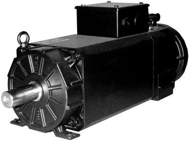
5 1. Three-phase asynchronous motor DA Due to the very high power density and huge flexibility achieved by its modular system, this range of motors is ideally suited for the most demanding applications in mechanical engineering. The motors have high setting ranges and feature roller bearings to cope with high lateral force loads. These durable, compact motors are also largely maintenance-free, which helps ensure efficient operation. The use of liquid cooling makes for a highly compact design and also reduces noise emissions General technical data Version IM B3, B5 Frame size 100 / 132 / 160 IM B3, B35 Frame size 180 / 225 IM B3 Frame size 280 Connection Main connection U V W (Terminal box) Control connection 12-pin connector, 17-pin connector with ENDAT interface Thermal sensor In the main connection Brake Axial ventilation: 8-pin connector Radial ventilation or water cooling: Terminal design Thermal sensor Linear thermal sensor For evaluation in the controller Temperature rise Δϑ 105K Insulation class F acc. to EN Environmental conditions for running Environmental conditions for long-term storage Environmental conditions for transport Class 3K3/3Z12 as per DIN EN , however: temperature range 0-40 C Class 1K2/1M1 DIN EN , however: temperature range C Class 2K2/2M1 DIN EN , however: temperature range C Represents 0 to 40 C at 5 % to 85 % rel. humidity and an absolute humidity of 1 g/m³ to 25 g/m³ and an installation height up to approx. 1,400 m. Represents -15 to 60 C at 5 % to 85 % rel. humidity and an absolute humidity of 1 g/m³ to 25 g/m³; at temperatures below 3 C you should drain the cooling water Represents -15 to 60 C at 5 % to 85 % rel. humidity and an absolute humidity of 1 g/m³ to 25 g/m³; at temperatures below 3 C you should drain the cooling water Shaft end Cylindrical According to DIN 748 without key Centering with internal thread acc. to DIN 332 form D Also available with key DIN 6885 as an option (consider torque) Bearing D-side N-side Standard = ball bearing; option = roller bearing Ball bearing, locating bearing Surface Black matt RAL 9005 Actual encoder 2-pin resolver Standard see chapter 3.2 Sincos Encoder Option see chapter 3.2; other encoders on request Brake Disk brakes from N-side mounting as a module, other brands on request Baumüller UL design CE Standard Order options: Size DA /13 Technical alterations reserved Baumüller Nürnberg GmbH 5
6 Technical data for air-cooled motors Type of protection / cooling method IP23 / IC06 IP54 / IC641 Internally ventilated with fan Surface-cooled with fan DA 100 Axial fan on N-side; Air conduction D-side to N-side, axial air outlet at N-side integrated fan DA Standard: Standard fan motor for axial ventilation on the N-side; option: Axially integrated fan on the N-side; option: Standard fan motor for Air conduction from D-side to N-side, lateral air outlet at N-side Air conduction from D-side to N-side, lateral air outlet at N-side Air conduction from N-side to D-side, lateral air outlet at D-side radial ventilation on the N-side DA 280 Radial fan at N-side; mounted standard motor Air conduction from N-side to D-side, lateral air outlet at D-side Fan motor connection Mounted standard motor Terminal box of standard motor Integrated fan motor 6-pin connector Vibration-resistant DA 100 Radial 0.5 g / axial 0.5 g 10 Hz Hz acc. to EN Vibration-resistant Radial 3 g / axial 1 g 10 Hz - 55 Hz acc. to EN DA Terminal box with axial N-end Above; With left and right-hand options ventilation Terminal box with radial ventilation D-end Right; With left-hand or above options Technical data for liquid-cooled motors Type of protection/cooling IP54/ IC3W7 Water-cooled machine method Vibration-resistant Radial 3 g / axial 1 g 10 Hz - 55 Hz acc. to EN DA Terminal box N-side; top Coolant input temperature 10 C to 35 C Consider how ambient temperature/humidity can affect the accumulation of condensed water, and how this phenomenon can be avoided. Water connection D-side lateral 1.2. General safety instructions The standard versions of the motors are unsuitable for operation in salty or aggressive atmospheres and are not suitable for erection outdoors. If, with an air-cooled motor, the air is contaminated with dust particles or similar substances in the surrounding air, which cannot be kept out efficiently by the filter elements in use, then the a conversation with the manufacturer is necessary to find a solution to the problem. CAUTION: With allocation of the motor in a specific protection class, it is a standardized brief test procedure. This can vary considerably depending on the actual environmental conditions at the site of installation. Depending on the environmental conditions, such as the chemical consistency of the dust materials or the cooling media being used at the site of installation, evaluation of the suitability of the motor based on the type of protection is only possible to a limited extent (e.g. electrically conducting dust materials or aggressive coolant vapors or coolant fluids). In these cases the motor must additionally be protected by appropriate measures on the machine side. Technical alterations reserved 01/13 DA Baumüller Nürnberg GmbH
7 1.3. Definitions of power ratings Definitions of power ratings for air-cooled machines The power ratings (torques) listed in the table apply to continuous operation (S1) at the rated and a maximum ambient temperature of 40 C, for machines installed below 1,000 m a.m.s.l. If motors are to be operated at an ambient temperature of more than 40 C, or altitudes above 1,000 m a.m.s.l., the required list power rating P L (list torque M n ) is calculated from the product of factors k 1 and k 2 (specified in the table below) and the required power rating P (torque M). Ambient temperature 40 C 45 C 50 C 55 C 60 C Correction factor k Altitude a.m.s.l. up to 1,000 m 2,000 m 3,000 m 4,000 m 5,000 m Correction factor k Design changes may be necessary in the case of ambient temperatures above 40 C and installation of motors in an enclosure: For this reason, it is imperative that the manufacturer is contacted. If, in the case of an increasing site altitude above 1,000 m, the ambient temperature decreases by approx. 10 C per 1,000 m increase, no power correction is necessary (note the minimum operating temperature) Definitions of power ratings for water-cooled machines The power ratings (torques) that appear in the list apply to permanent operation S1 at nominal, provided the cooling circuit requirements for water-cooled motors are met! The reduction factors included in the table below must be considered when operating DSD2 motors with higher coolant inlet temperatures: Coolant inlet temperature 35 C 40 C 45 C Percentage of list performance (torque) 100 % 97 % 95 % 1.4. Water cooling Coolant consistency Conditions Unit Value Maximum permitted system pressure bar 6 Temperature of coolant - for motor C 10 to 35 ph value (at 20 C) to 9 Overall hardness mmol/l 1.43 to 2.5 Chloride - Cl - mg/l < 200 Sulphate - SO 4 ² - mg/l < 200 Oil mg/l < 1 Permitted particle size of solid foreign objects, particles (e.g. sand) mm < 0.1 Clean water that is free of dirt and suspended matter must be used as a coolant. DA /13 Technical alterations reserved Baumüller Nürnberg GmbH 7
8 Min. coolant temperature against ambient temperature and humidity min. coolant temperature ( C) % rel. humidity 75% rel. humidity 65% rel. humidity 55% rel. humidity 45% rel. humidity 35% rel. humidity 25% rel. humidity ambient temperature ( C) The allowed coolant temperature depends on relative humidity and ambient temperature. For example with an ambient temperature of 25 C and a relative humidity of 65% the minimum coolant temperature is 18 C. Because these are limiting values on practical side a coolant temperature greater than 18 C should be used. If this minimum coolant temperature will be under run the two- point controller of Baumüller drive must be used to avoid condensation. Technical alterations reserved 01/13 DA Baumüller Nürnberg GmbH
9 Start T water T ambience -5K No Definition rel. humidity Definition of min. coolant temperature (diagram 1.4.2) Yes T water > T min.water (diagram 1.4.2) No T water 35 C No Yes Yes No restrictions Derating referred to table No T water 35 C Yes 2-point controller T on = 70 C T off = 50 C No restrictions No T water 35 C Yes No restrictions Note: The supply of cooling fluid must be interrupted to prevent condensation when storing for an extended period. In addition, at ambient temperatures < 3 C and if the motor has not run for an extended period, drain the cooling fluid to prevent damage caused by frost. When using anti-freeze you need to consult the manufacturer. DA /13 Technical alterations reserved Baumüller Nürnberg GmbH 9
10 Details relating to the amounts of coolant required DA frame size Min. flow rate [l/min] 7 (5) 9 (6.5) 11 (9) 12 (10) 13 (11) 17 (14.5) Pressure drop [bar] 0.3 ±10 % 0.3 ±10 % 1.1 ±10 % 1.4 ±10 % 2.6 ±10 % 2.6 ±10 % Max. temperature rise [K] 6 (9) 7 (10) 8 (10) 10 (12) 11 (13) 11 (13) Max. coolant pressure [bar] Connection (G-internal thread) 2x 1/2 2x 1/2 4x 1/4 4x 1/4 4x 1/4 4x 3/8 Sufficient quantities of additives for corrosion and germ protection must be mixed in. The additive type and dosage are based on recommendations from the additive manufacturer and the prevailing ambient conditions Materials in the motor that make contact with the medium The following materials that make contact with the medium are used in the motor: Size Cooling system: Cathodic dip painted aluminum Connections: Galvanized steel Seals: NBR seals Size : Cooling system: Stainless steel Connections: Brass Seals: Vulcanized fiber 1.5. Winding insulation The motors are designed for an operation on converters with intermediate link voltages of up to 640V. Higher intermediate link voltages of up to 800V are possible, if voltage spikes on the motor terminals are limited to < 1200 V by suitable filters in the motor supply line. Technical alterations reserved 01/13 DA Baumüller Nürnberg GmbH
11 1.6. Explanation of the motor data n N Nominal ( rpm ) P N Nominal power ( kw ) with nominal nn in continuous operation (S1) M N Nominal torque ( kw ) with nominal nn in continuous operation (S1) I N Nominal r.m.s. ( A ) at nominal nr in continuous operation (S1); TA= 40 C U N Nominal voltage ( V ) n 1 Limit for field weakening (constant power) (rpm ) n max mechanically permissible operating (rpm ) cos ϕ Power factor Iμ Magnetizing (A) η N Efficiency f N Nominal frequency (Hz) M 0, max, Maximum standstill torque (Nm) at maximum (A) at = 0 J Rotor inertia incl. resolver without holding brake (kgm²) m Weight (kg) When the converter is operating, the specified rated outputs and torques at the rated are achieved with a clocking frequency of 4 khz in the power divider. A clocking frequency of > 6 khz is recommended. All converters scheduled for use must have the option of field weakening as a mandatory requirement. The sizemaxx drive configurator is available at for designing the motors and the overall drive system Noise intensity The ventilated motors do not exceed the limit values specified in EN A converter clock frequency of > 6 khz is recommended. Noise level Motor frame size Type of protection IP 23 Type of protection IP 54, surfacecooled Type of protection IP 54, watercooled DA ± 3 dba 71 ± 3 dba DA ± 3 dba 74 ± 3 dba 72 ± 3 dba DA ± 3 dba 76 ± 3 dba 74 ± 3 dba DA ± 3 dba 78 ± 3 dba 75 ± 3 dba DA ± 3 dba 80 ± 3 dba 76 ± 3 dba DA ± 3 dba - 78 ± 3 dba DA /13 Technical alterations reserved Baumüller Nürnberg GmbH 11
12 1.8. Type key DA FF G 225 M 54 A 17 5 UL approval UL Motor with UL approval DC link 5 540V voltage: 6 640V Nominal rpm Cooling method W A R Water cooling Axially mounted separate fan Radially mounted separate fan Type of protection Length: 54 IP54 23 IP23 K M L B Frame size Brake G Brake Design F Flange-mounting FF Footflange mounting Motor type DA Three-phase asynchronous motor Technical alterations reserved 01/13 DA Baumüller Nürnberg GmbH
13 2. Technical data 2.1. DA DA A.. (IP 54 surface-cooled) Mains voltage 3 AC 400 V for converters with uncontrolled supply Motor type power torque voltage Max. operat. Power factor Limit with field weakening Magnetizing Efficiency Frequency n N P N M N I N U N n 1 n max cos ϕ I μ η N f N min -1 kw Nm A V min -1 min -1 A Hz 1000 DA100K54A DA100M54A DA100L54A DA100B54A DA100K54A DA100M54A DA100L54A DA100B54A DA100K54A DA100M54A DA100L54A DA100B54A DA100K54A DA100M54A DA100L54A DA100B54A DA /13 Technical alterations reserved Baumüller Nürnberg GmbH 13
14 Mains voltage 3 AC 480 V for converters with uncontrolled supply Motor type power torque voltage Max. operat. Power factor Limit with field weakening Magnetizing Efficiency Frequency n N P N M N I N U N n 1 n max cos ϕ I μ η N f N min -1 kw Nm A V min -1 min -1 A Hz 1000 DA100K54A DA100M54A DA100L54A DA100B54A DA100K54A DA100M54A DA100L54A DA100B54A DA100K54A DA100M54A DA100L54A DA100B54A DA100K54A DA100M54A DA100L54A DA100B54A Motor type Maximum standstill torque M 0 max [Nm] Inertia J [kgm 2 ] Weight m [kg] DA100K54A DA100M54A DA100L54A DA100B54A Technical alterations reserved 01/13 DA Baumüller Nürnberg GmbH
15 DA W.. (IP 54 water-cooled) Mains voltage 3 AC 400 V for converters with uncontrolled supply Motor type power torque voltage Max. operat. Power factor Limit with field weakening Magnetizing Efficiency Frequency n N P N M N I N U N n 1 n max cos ϕ I μ η N f N min -1 kw Nm A V min -1 min -1 A Hz 1000 DA100K54W DA100M54W DA100L54W DA100B54W DA100K54W DA100M54W DA100L54W DA100B54W DA100K54W DA100M54W DA100L54W DA100B54W DA100K54W DA100M54W DA100L54W DA100B54W DA100K54W DA100M54W DA100L54W DA100B54W Motor type Maximum standstill torque M 0 max [Nm] Inertia J [kgm 2 ] Weight m [kg] DA100K54W DA100M54W DA100L54W DA100B54W DA /13 Technical alterations reserved Baumüller Nürnberg GmbH 15
16 2.2. DA DA A(R).. (IP 23 internally ventilated) Mains voltage 3 AC 400 V for converters with uncontrolled supply Motor type power torque voltage Max. operat. Power factor Limit with field weakening Magnetizing Efficiency Frequency n N P N M N I N U N n 1 n max cos ϕ I μ η N f N min -1 kw Nm A V r min -1 min -1 A Hz 1000 DA132K23A DA132M23A DA132L23A DA132B23A DA132K23A DA132M23A DA132L23A DA132B23A DA132K23A DA132M23A DA132L23A DA132B23A DA132K23A DA132M23A DA132L23A DA132B23A Technical alterations reserved 01/13 DA Baumüller Nürnberg GmbH
17 Mains voltage 3 AC 480 V for converters with uncontrolled supply Motor type power torque voltage Max. operat. Power factor Limit with field weakening Magnetizing Efficiency Frequency n N P N M N I N U N n 1 n max cos ϕ I μ η N f N min -1 kw Nm A V min -1 min -1 A Hz 1000 DA132K23A DA132M23A DA132L23A DA132B23A DA132K23A DA132M23A DA132L23A DA132B23A DA132K23A DA132M23A DA132L23A DA132B23A DA132K23A DA132M23A DA132L23A DA132B23A Motor type Maximum standstill torque M 0 max [Nm] Inertia J [kgm 2 ] Weight m [kg] DA132K23A/R DA132M23A/R DA132L23A/R DA132B23A/R DA /13 Technical alterations reserved Baumüller Nürnberg GmbH 17
18 DA A(R).. (IP 54 surface-cooled) Mains voltage 3 AC 400 V for converters with uncontrolled supply Motor type power torque voltage Max. operat. Power factor Limit with field weakening Magnetizing Efficiency Frequency n N P N M N I N U N n 1 n max cos ϕ I μ η N f N min -1 kw Nm A V min -1 min -1 A Hz 1000 DA132K54A DA132M54A DA132L54A DA132B54A DA132K54A DA132M54A DA132L54A DA132B54A DA132K54A DA132M54A DA132L54A DA132B54A DA132K54A DA132M54A DA132L54A DA132B54A Technical alterations reserved 01/13 DA Baumüller Nürnberg GmbH
19 Mains voltage 3 AC 480 V for converters with uncontrolled supply Motor type power torque voltage Max. operat. Power factor Limit with field weakening Magnetizing Efficiency Frequency n N P N M N I N U N n 1 n max cos ϕ I μ η N f N min -1 kw Nm A V min -1 min -1 A Hz 1000 DA132K54A DA132M54A DA132L54A DA132B54A DA132K54A DA132M54A DA132L54A DA132B54A DA132K54A DA132M54A DA132L54A DA132B54A DA132K54A DA132M54A DA132L54A DA132B54A Motor type Maximum standstill torque M 0 max [Nm] Inertia J [kgm 2 ] Weight m [kg] DA132K54A/R DA132M54A/R DA132L54A/R DA132B54A/R DA /13 Technical alterations reserved Baumüller Nürnberg GmbH 19
20 DA W.. (IP 54 water-cooled) Mains voltage 3 AC 400 V for converters with uncontrolled supply Motor type power torque voltage Max. operat. Power factor Limit with field weakening Magnetizing Efficiency Frequency n N P N M N I N U N n 1 n max cos ϕ I μ η N f N min -1 kw Nm A V min -1 min -1 A Hz 1000 DA132K54W DA132M54W DA132L54W DA132B54W DA132K54W DA132M54W DA132L54W DA132B54W DA132K54W DA132M54W DA132L54W DA132B54W DA132K54W DA132M54W DA132L54W DA132B54W DA132K54W DA132M54W DA132L54W DA132B54W Motor type Maximum standstill torque M 0 max [Nm] Inertia J [kgm 2 ] Weight m [kg] DA132K54W DA132M54W DA132L54W DA132B54W Technical alterations reserved 01/13 DA Baumüller Nürnberg GmbH
21 2.3. DA DA A(R).. (IP 23 internally ventilated) Mains voltage 3 AC 400 V for converters with uncontrolled supply Motor type power torque voltage Max. operat. Power factor Limit with field weakening Magnetizing Efficiency Frequency n N P N M N I N U N n 1 n max cos ϕ I μ η N f N min -1 kw Nm A V min -1 min -1 A Hz 400 DA160K23A DA160M23A DA160L23A DA160K23A DA160M23A DA160L23A DA160K23A DA160M23A DA160L23A DA160K23A DA160M23A DA160L23A DA160K23A DA160M23A DA160L23A DA /13 Technical alterations reserved Baumüller Nürnberg GmbH 21
22 Mains voltage 3 AC 480 V for converters with uncontrolled supply Motor type power torque voltage Max. operat. Power factor Limit with field weakening Magnetizing Efficiency Frequency n N P N M N I N U N n 1 n max cos ϕ I μ η N f N min -1 kw Nm A V min -1 min -1 A Hz 400 DA160K23A DA160M23A DA160L23A DA160K23A DA160M23A DA160L23A DA160K23A DA160M23A DA160L23A DA160K23A DA160M23A DA160L23A DA160K23A DA160M23A DA160L23A Motor type Maximum standstill torque M 0 max [Nm] Inertia J [kgm 2 ] Weight m [kg] DA160K23A/R DA160M23A/R DA160L23A/R Technical alterations reserved 01/13 DA Baumüller Nürnberg GmbH
23 DA A(R).. (IP 54 surface-cooled) Mains voltage 3 AC 400 V for converters with uncontrolled supply Motor type power torque voltage Max. operat. Power factor Limit with field weakening Magnetizing Efficiency Frequency n N P N M N I N U N n 1 n max cos ϕ I μ η N f N min -1 kw Nm A V min -1 min -1 A Hz 400 DA160K54A DA160M54A DA160L54A DA160K54A DA160M54A DA160L54A DA160K54A DA160M54A DA160L54A DA160K54A DA160M54A DA160L54A DA160K54A DA160M54A DA160L54A DA160K54A DA160M54A DA160L54A DA /13 Technical alterations reserved Baumüller Nürnberg GmbH 23
24 Mains voltage 3 AC 480 V for converters with uncontrolled supply Motor type power torque voltage Max. operat. Power factor Limit with field weakening Magnetizing Efficiency Frequency n N P N M N I N U N n 1 n max cos ϕ I μ η N f N min -1 kw Nm A V min -1 min -1 A Hz 400 DA160K54A DA160M54A DA160L54A DA160K54A DA160M54A DA160L54A DA160K54A DA160M54A DA160L54A DA160K54A DA160M54A DA160L54A DA160K54A DA160M54A DA160L54A DA160K54A DA160M54A DA160L54A Motor type Maximum standstill torque M 0 max [Nm] Inertia J [kgm 2 ] Weight m [kg] DA160K54A/R DA160M54A/R DA160L54A/R Technical alterations reserved 01/13 DA Baumüller Nürnberg GmbH
25 DA W.. (IP 54 water-cooled) Mains voltage 3 AC 400 V for converters with uncontrolled supply Motor type power torque voltage Max. operat. Power factor Limit with field weakening Magnetizing Efficiency Frequency n N P N M N I N U N n 1 n max cos ϕ I μ η N f N min -1 kw Nm A V min -1 min -1 A Hz 1000 DA160K54W DA160M54W DA160L54W DA160K54W DA160M54W DA160L54W DA160K54W DA160M54W DA160L54W DA160K54W DA160M54W DA160L54W DA160K54W DA160M54W DA160L54W Motor type Maximum standstill torque M 0 max [Nm] Inertia J [kgm 2 ] Weight m [kg] DA160K54W DA160M54W DA160L54W DA /13 Technical alterations reserved Baumüller Nürnberg GmbH 25
26 2.4. DA DA A(R).. (IP 23 internally ventilated) Mains voltage 3 AC 400 V for converters with uncontrolled supply Motor type power torque voltage Max. operat. Power factor Limit with field weakening Magnetizing Efficiency Frequency n N P N M N I N U N n 1 n max cos ϕ I μ η N f N min -1 kw Nm A V min -1 min -1 A Hz 400 DA180M23A DA180L23A DA180M23A DA180L23A DA180M23A DA180L23A DA180M23A DA180L23A DA180M23A DA180L23A Mains voltage 3 AC 480 V for converters with uncontrolled supply Motor type power torque voltage Max. operat. Power factor Limit with field weakening Magnetizing Efficiency Frequency n N P N M N I N U N n 1 n max cos ϕ I μ η N f N min -1 kw Nm A V min -1 min -1 A Hz 400 DA180M23A DA180L23A DA180M23A DA180L23A DA180M23A DA180L23A DA180M23A DA180L23A DA180M23A DA180L23A Motor type Maximum standstill torque M 0 max [Nm] Inertia J [kgm 2 ] Weight m [kg] DA180M23A/R DA180L23A/R Technical alterations reserved 01/13 DA Baumüller Nürnberg GmbH
27 DA A(R).. (IP 54 surface-cooled) Mains voltage 3 AC 400 V for converters with uncontrolled supply Motor type power torque voltage Max. operat. Power factor Limit with field weakening Magnetizing Efficiency Frequency n N P N M N I N U N n 1 n max cos ϕ I μ η N f N min -1 kw Nm A V min -1 min -1 A Hz 400 DA180M54A DA180L54A DA180M54A DA180L54A DA180M54A DA180L54A DA180M54A DA180L54A DA180M54A DA180L54A DA180M54A DA180L54A Mains voltage 3 AC 480 V for converters with uncontrolled supply Motor type power torque voltage Max. operat. Power factor Limit with field weakening Magnetizing Efficiency Frequency n N P N M N I N U N n 1 n max cos ϕ I μ η N f N min -1 kw Nm A V min -1 min -1 A Hz 400 DA180M54A DA180L54A DA180M54A DA180L54A DA180M54A DA180L54A DA180M54A DA180L54A DA180M54A DA180L54A DA180M54A DA180L54A Motor type Maximum standstill torque M 0 max [Nm] Inertia J [kgm 2 ] Weight m [kg] DA180M54A/R DA180L54A/R DA /13 Technical alterations reserved Baumüller Nürnberg GmbH 27
28 DA W.. (IP 54 water-cooled) Mains voltage 3 AC 400 V for converters with uncontrolled supply Motor type power torque voltage Max. operat. Power factor Limit with field weakening Magnetizing Efficiency Frequenc n N P N M N I N U N n 1 n max cos ϕ I μ η N f N min -1 kw Nm A V min -1 min -1 A Hz 1000 DA180M54W DA180L54W DA180M54W DA180L54W DA180M54W DA180L54W DA180M54W DA180L54W DA180MW DA180L54W Motor type Maximum standstill torque M 0 max [Nm] Inertia J [kgm 2 ] Weight m [kg] DA180M54W DA180L54W Technical alterations reserved 01/13 DA Baumüller Nürnberg GmbH
29 2.5. DA DA A(R).. (IP 23 internally ventilated) Mains voltage 3 AC 400 V for converters with uncontrolled supply Motor type power torque voltage Max. operat. Power factor Limit with field weakening Magnetizing Efficiency Frequency n N P N M N I N U N n 1 n max cos ϕ I μ η N f N min -1 kw Nm A V min -1 min -1 A Hz 400 DA225K23A DA225M23A DA225L23A DA225K23A DA225M23A DA225L23A DA225K23A DA225M23A DA225K23A DA225M23A DA225L23A DA225K23A DA225M23A DA225K23A DA225M23A DA225K23A DA /13 Technical alterations reserved Baumüller Nürnberg GmbH 29
30 Mains voltage 3 AC 480 V for converters with uncontrolled supply Motor type power torque voltage Max. operat. Power factor Limit with field weakening Magnetizing Efficiency Frequency n N P N M N I N U N n 1 n max cos ϕ I μ η N f N min -1 kw Nm A V min -1 min -1 A Hz 400 DA225K23A DA225M23A DA225L23A DA225K23A DA225M23A DA225L23A DA225K23A DA225M23A DA225K23A DA225M23A DA225L23A DA225K23A DA225M23A DA225K23A DA225M23A DA225K23A Motor type Maximum standstill torque M 0 max [Nm] Inertia J [kgm 2 ] Weight m [kg] DA225K23A/R DA225M23A/R DA225L23A/R Technical alterations reserved 01/13 DA Baumüller Nürnberg GmbH
31 DA A(R).. (IP 54 surface-cooled) Mains voltage 3 AC 400 V for converters with uncontrolled supply Motor type power torque voltage Max. operat. Power factor Limit with field weakening Magnetizing Efficiency Frequency n N P N M N I N U N n 1 n max cos ϕ I μ η N f N min -1 kw Nm A V min -1 min -1 A Hz 400 DA225K54A DA225M54A DA225L54A DA225K54A DA225M54A DA225L54A DA225K54A DA225M54A DA225L54A DA225K54A DA225M54A DA225L54A DA225K54A DA225M54A DA225L54A DA225K54A DA225M54A DA /13 Technical alterations reserved Baumüller Nürnberg GmbH 31
32 Mains voltage 3 AC 480 V for converters with uncontrolled supply Motor type power torque voltage Max. operat. Power factor Limit with field weakening Magnetizing Efficiency Frequency n N P N M N I N U N n 1 n max cos ϕ I μ η N f N min -1 kw Nm A V min -1 min -1 A Hz 400 DA225K54A DA225M54A DA225L54A DA225K54A DA225M54A DA225L54A DA225K54A DA225M54A DA225L54A DA225K54A DA225M54A DA225L54A DA225K54A DA225M54A DA225L54A DA225K54A DA225M54A Motor type Maximum standstill torque M 0 max [Nm] Inertia J [kgm 2 ] Weight m [kg] DA225K54A/R DA225M54A/R DA225L54A/R Technical alterations reserved 01/13 DA Baumüller Nürnberg GmbH
33 DA W.. (IP 54 water-cooled) Mains voltage 3 AC 400 V for converters with uncontrolled supply Motor type power torque voltage Max. operat. Power factor Limit with field weakening Magnetizing Efficiency Frequency n N P N M N I N U N n 1 n max cos ϕ I μ η N f N min -1 kw Nm A V min -1 min -1 A Hz 1000 DA225K54W DA225M54W DA225L54W DA225K54W DA225M54W DA225K54W DA225M54W DA225L54W DA225K54W DA225M54W DA225L54W DA225K54W DA225M54W DA225K54W Motor type Maximum standstill torque M 0 max [Nm] Inertia J [kgm 2 ] Weight m [kg] DA225K54W DA225M54W DA225L54W DA /13 Technical alterations reserved Baumüller Nürnberg GmbH 33
34 2.6. DA DA R.. (IP 23 internally ventilated) Mains voltage 3 AC 400 V for converters with uncontrolled supply Motor type power torque curren voltage Max. operat. Power factor Limit with field weakening Magnetizing Efficiency Frequenc n N P N M N I N U N n 1 n max cos ϕ I μ η N f N min -1 kw Nm A V min -1 min -1 A Hz 750 DA280K23R DA280M23R DA280L23R DA280K23R DA280M23R DA280L23R DA280K23R DA280M23R DA280K23R Motor type Maximum standstill torque M 0 max [Nm] Inertia J [kgm 2 ] Weight m [kg] DA280K23R DA280M23R DA280L23R Technical alterations reserved 01/13 DA Baumüller Nürnberg GmbH
35 DA W.. (IP 54 water-cooled) Mains voltage 3 AC 400 V for converters with uncontrolled supply Motor type power torque voltage Max. operat. Power factor Limit with field weakening Magnetizing Efficiency Frequency n N P N M N I N U N n 1 n max cos ϕ I μ η N f N min -1 kw Nm A V min -1 min -1 A Hz 750 DA280K54W DA280M54W DA280L54W DA280K54W DA280M54W DA280L54W DA280K54W DA280M54W DA280L54W DA280K54W DA280M54W DA280K54W Motor type Maximum standstill torque M 0 max [Nm] Inertia J [kgm 2 ] Weight m [kg] DA280K54W DA280M54W DA280L54W DA /13 Technical alterations reserved Baumüller Nürnberg GmbH 35
36 2.7. Bearings and shaft load All machines are equipped with rolling-contact bearings. Normally, the non-locating bearing (ball bearing) is intended for the drive end and the locating bearing (ball bearing) for the non-drive end. Machines with roller bearings at the drive end are available for applications where increased radial forces can occur, for instance when using pulleys. Please specify radial forces in your order. Ball bearing assignment for D-side Frame size D-side N-side ZRC ZRC ZRC ZRC ZRC ZRC ZRC ZRC ZRC ZRC C C3 Roller bearing assignment for D-side Frame size D-side N-side 100 NU 209 E ZRC3 132 NU 312 E ZRC3 160 NU 313 E ZRC3 180 NU 314 E ZRC3 225 NU 316 E ZRC3 280 NU 2220 E 6220 C3 The bearings at motor size have a permanent lubrication. The bearings at motor size 280 have a relubrication device. The bearings at motor size are on the N-side in insulated version by default. NOTE: In the option "roller bearings for D-side" the rotor is secured by default with a transport lock. The transport lock must be fixed during the transport and must first be removed before reassembling a driven element. If the machine will be transport after mounting of a driven element, a suitable method for the axial and radial fixation of the rotor must are taken. Determination of radial forces F R When using pulleys, the radial load is calculated according to the following formula: P N = Nominal power in kw 7 n = Nominal in rpm 2 10 PN F = k [N] R n D D = Pulley diameter in mm The belt tightening factor k is approximately: k = for V-belt k = for flat belt (Observe specifications of the belt manufacturer) To ensure safe and reliable torque transmission, it is necessary to utilize the entire bearing length of the key. Otherwise, the key may be subjected to an excessive compressive load per unit area, which in turn can result in the failure of the motor. The pulley must be mounted up to the shaft shoulder and only tightened to the following maximum tightening torques. Gland M5 M6 M8 M10 M12 M16 M20 Tightening torque 2.2 Nm 4.0 Nm 10.0 Nm 19.0 Nm 33.0 Nm 80 Nm 160 Nm Permissible radial forces F R at the shaft end The ball bearings have been dimensioned for a calculated service life of approx. 20,000 operating hours 1). The load values specified below must not be exceeded. The specified permissible radial forces F R are only valid for horizontal mounting of the motor without additional axial forces. If additional axial forces are involved, please consult the manufacturer. Axial load on the motor shaft When mounting clutches, pulleys, etc. onto the motor shaft, axial forces must not occur! Therefore, use the internal thread of the shaft end as an assembly aid. 1) medium operating temperature < 90 C medium operating < 2000 rpm (DA ), medium operating sped < 1500 rpm (DA ) Technical alterations reserved 01/13 DA Baumüller Nürnberg GmbH
37 2.8. Radial force diagrams Example A Shaft B 300 n [ rpm ] M [ Nm ] Ball bearing Roller bearing Fr [ N ] Kugellager / Ball bearing Rollenlager / Roller bearing Welle / Shaft Explanation of the example diagram Force acting on the end of the shaft end (for force acting on the middle of the shaft end Fr x 1.1) Shaft end with keyway Case A Ball bearing: The radial force Fr of the application is used to determine the possible maximum of the bearing in the Ball bearing characteristic. Radial force N => maximum rpm The maximum transmittable torque is based on the Shaft characteristic. Radial force N => maximum transmittable torque 450 Nm Case B Roller bearing: The radial force Fr of the application is used to determine the possible maximum of the bearing in the Roller bearing characteristic. Radial force N => maximum rpm The maximum transmittable torque is based on the Shaft characteristic. Radial force N => maximum transmittable torque 345 Nm DA /13 Technical alterations reserved Baumüller Nürnberg GmbH 37
38 DA 100 n in [ rpm ] M in [ Nm ] Fr in [ N ] Rollenlager / Roller bearing Kugellager / Ball bearing Welle / Shaft DA n in [ 1/min ] Fr in [ N ] M in [ Nm ] Kugellager / Ball bearing Rollenlager / Roller bearing Welle / Shaft Technical alterations reserved 01/13 DA Baumüller Nürnberg GmbH
39 DA 160 n in [ rpm ] Fr in [ N ] Kugellager / Ball bearing Rollenlager / Roller bearing Welle / Shaft M in [ Nm ] DA 180 n in [ 1/min ] Fr in [ N ] M in [ Nm ] Kugellager / Ball bearing Rollenlager / Roller bearing Welle / Shaft DA /13 Technical alterations reserved Baumüller Nürnberg GmbH 39
40 DA n in [ rpm ] M in [ Nm ] Fr in [ N ] Kugellager / Ball bearing Rollenlager / Roller bearing Welle / Shaft Technical alterations reserved 01/13 DA Baumüller Nürnberg GmbH
41 3. Motor components (options) 3.1. Holding brake For motor type Brake type Brake torque M B for holding brake Input power Max. perm. switching energy Wperm. per switching operation Disengaging time Engaging time Inertia Max. perm. [Nm)] [W] [kj] [s] [s] [kgm²] [rpm ] [kg] DAG 100 A SB DAG 100 W SB DAG 132 SB DAG 160 SB DAG 180 On request DAG 225 On request DAG 280 On request Weight For use as a holding brake the following must be observed: 3 emergency stops (individual braking operations) per hour are possible if evenly distributed Switching times values are valid for switching on the AC side, in a cold state, with basic air gap and holding brake Disengaging time Time until the brake has completely disengaged (brake without torque) Engaging time Time until the brake torque is reached All information is valid for installation on a horizontal shaft. The supplier must be contacted before vertical installation. Requirements other than those indicated can be catered for on request Brake time / Switching energy It is necessary to check that the brake is suited for its application. For this, the switching energy must be determined. Determination of the braking time [t B ] t B J * Δn tb = + t0 9,55 * (MB ± ML ) in s J Total moment of inertia in kgm² = J mot + J add (referred to motor shaft) J mot Motor moment of inertia in kgm² J add Additional moment of inertia in kgm² (referred to motor shaft) Δn Motor in rpm M B Brake torque in Nm M L Load torque in Nm (positively calculated if it decelerates, negatively calculated if it accelerates) t 0 Time in s from the switching instant to the full extent of the braking torque (response time) I Number of cycles per hour Determining the switching energy [W R ] Determining the switching capacity [P R ] W R = J Δn M B (M ± M B L ) joules in switching operation P R = W R 1000 i in kj h W Rperm value from table In most cases, t 0 is negligible. If this is not the case and the time t 0 must be reduced, you can achieve this by interrupting the magnet circuit on the DC side. However, this measure must be known before dimensioning the brake motor. DA /13 Technical alterations reserved Baumüller Nürnberg GmbH 41
. The silver contacts are coated with a layer of gold, which enables two applications.")

42 Brake supply Standard: Normal voltage 24 DC Supply with transformer and rectifier Option: Normal voltage 104 and 176V DC Supply using brake supply unit The brake supply unit must be order separately. The brakes are designed with micro-switch (normally open contact). The silver contacts are coated with a layer of gold, which enables two applications. By maximum load of the gold layer, the gold layer can be burned irreversible. In this case, the contact material "gold layer" can not longer be used. Electrical data of the switches: Contact material Min. load Ideal range of use Max. load 0 ma; 0 V 0 ma; 0 V 10 ma; 12 V 0,1 A; 12 V Gold coat up to 3 Mio. cycles up to 3 Mio. cycles up to 1 Mio. cycles up to cycles 10 ma; 12 V 100 ma; 12 V 5 A; 30 V 5 A; 30 V Argent up to 3 Mio. cycles up to 3Mio. cycles up to cycles up to cycles The brakes can be executed optional with hand ventilation and lock Brake connection DAG for axial forced ventilation Connector: Mating plug size 1 for levels I 0 to 20 A Art. no : DAG for radial forced ventilation and water cooling Terminal: B B M M B - Brake M - Microswitch Brake attachment with radial forced ventilation on request. Technical alterations reserved 01/13 DA Baumüller Nürnberg GmbH
43 3.2. Encoder Resolver (LTN) RE-21 Pole pair number 1 Transmission ratio 0,5 ± 0,05 Frequency 5 khz Nominal input voltage 7 V rms Effective input power at no-load 112 mw Current consumption at no-load 70 ma Max. output voltage at no-load 3,5 V ± 10% Voltage constant 61 mv/ Rotor resistance 48 Ω ± 10% Stator resistance 31 Ω ± 15% Rotor impedance at no-load 70 + j 74Ω ± 15% Rotor impedance with short circuit 62 + j 66Ω ± 15% Stator impedance at no-load with minimum coupling j 206Ω ± 15% Stator impedance with short circuit and maximum coupling 97 + j 183Ω ± 15% Phase shift 8 ± 3 Zero voltage 30 mv Angle error in relation to (Δϕ max +Δϕ min )/2 ± 6 Shock according to DIN EN (11ms) 1000 m/s² Vibration according to DIN EN ( Hz) 500 m/s² Resolver connection View on the contact side of the receptacle Pin Signal cos sin - sin + - cos + - ref + - ref - NOTE: Use only at low demands on the true running characteristics of the motor. The technical data is specification from the encoder manufacturer. DA /13 Technical alterations reserved Baumüller Nürnberg GmbH 43
44 SINCOS SRS/SRM 50 (SICK/STEGMANN) SRS50 SRM50 Number of sine, cosine periods per revolution 1024 Number of increments per revolution Number of absolute resolved revolutions Code type for the absolute value binär Output frequency of the sine and cosine signals khz Error limits for evaluating the sine, cosine periods, integral nonlinearity +/- 45 Non-linearity within a sine, cosine, differential non-linearity at nominal position +/- 7 Operating until the absolute position can be formed 6000 rpm Max. operating rpm Output signals; 2 x 90 offset sinusoidal signals 1 V ss Output signal serial RS 485 asynchronous, half duplex Operating voltage range 7-12 V max. no-load operating 80 ma Shock according to DIN EN (10 ms) 100 g Vibration according to EN ( Hz) 20 g SRS/SRM 50 connection View on the contact side of the receptacle Pin Signal cos sin + sin cos + - GND - + U NOTE: This encoder is a component susceptible to ESD. The technical data is specification from the encoder manufacturer. Technical alterations reserved 01/13 DA Baumüller Nürnberg GmbH
45 ECN 1313/EQN 1325 (Heidenhain) ECN 1313 EQN 1325 Number of sine and cosine periods per revolution 2048 System accuracy ± 20 Number of absolute completed revolutions (12 bit) Code type for the absolute value EnDat 2.1 Sampling limit frequency or limit frequency khz Position values/revolution 8192 (13 bit ) Maximum at which the absolute position can be defined rpm Maximum operating rpm Power supply V Current consumption without load 160 ma 200 ma Shock 6ms according to DIN EN (6ms) 2000 m/s² Vibration Hz according to DIN EN ( Hz) 300 m/s² ECN 1313/EQN 1325 connection View on the contact side of the receptacle Pin Signal U p - - 0V - - U p Clock Clock inv. 0V - B + B - Data A + A - Data inv. NOTE: This encoder is a component susceptible to ESD. The technical data is specification from the encoder manufacturer. DA /13 Technical alterations reserved Baumüller Nürnberg GmbH 45
46 ECN 1325/EQN1337 (Heidenhain) ECN 1325 EQN 1337 Number of lines 2048 System accuracy ± 20 Number of absolute completed revolutions (12 bit) Code type for the absolute value EnDat 2.2 Position values/revolution (25 bit) Maximum at which the absolute position can be defined rpm Maximum operating rpm Power supply Current consumption without load 160 ma 200 ma Shock 6ms according to DIN EN (6ms) Vibration Hz according to DIN EN ( Hz) 2000 m/s² 300 m/s² ECN1325/EQN1337 connection View on the contact side of the receptacle Pin Signal Clock Clock inv. U p 0V Data Data inv. Sensor U p Sensor 0V - NOTE: This encoder is a component susceptible to ESD. The technical data is specification from the encoder manufacturer. Technical alterations reserved 01/13 DA Baumüller Nürnberg GmbH
47 ERN 1320 (Heidenhain) ERN 1320 Incremental signals TTL 1024/ ± 64 Line numbers/precision 2048/ ± / ± 16 Sample frequency 300 khz Maximum operational rpm Supply voltage 5 V ± 10 % Power consumption without load 120 ma Shock according to DIN EN (6 ms) 1000 m/s² Vibration according to DIN EN ( Hz) 300 m/s² ERN 1320 connection View on the contact side of the receptacle Pin Signal U2 - U p sense U0 + U0 - U1 + U1 - - U V 0V sense U p NOTE: This encoder is a component susceptible to ESD. The technical data is specification from the encoder manufacturer. DA /13 Technical alterations reserved Baumüller Nürnberg GmbH 47
48 ERN 1380 (Heidenhain) ERN 1380 Incremental signals 1 V SS Line numbers/precision 1024/ ± 40 Cut-off frequency -3 db 210 khz Maximum operational rpm Supply voltage 5 V ± 10 % Power consumption without load 120 ma Shock according to DIN EN (6 ms) 2000 m/s² Incremental signals 300 m/s² ERN 1380 connection View on the contact side of the receptacle Pin Signal U V sense U0 + U0 - U1 + U1 - - U V 0V sense UG NOTE: This encoder is a component susceptible to ESD. The technical data is specification from the encoder manufacturer. Technical alterations reserved 01/13 DA Baumüller Nürnberg GmbH
49 ERN 1385 (Heidenhain) ERN 1385 Incremental signals 1 V SS Line numbers/precision 2048/ ± 20 Sample frequency 300 khz Maximum operational rpm Supply voltage 5 V ± 5 % Power consumption without load 130 ma Shock according to DIN EN (6 ms) 1000 m/s² Vibration according to DIN EN ( Hz) 300 m/s² ERN 1385 connection View on the contact side of the receptacle Pin Signal A + A - R + D - C + C - M-Encoder TM + TM - P-Encoder B + B - R - D + 0V sense 5V sense - NOTE: This encoder is a component susceptible to ESD. The technical data is specification from the encoder manufacturer. DA /13 Technical alterations reserved Baumüller Nürnberg GmbH 49
50 DFS60 (SICK/Stegmann) Incremental signals Line numbers Maximum output frequency Maximum operational Operating voltage range Operational without load Shock according to DIN EN (6 ms) Vibration according to DIN EN ( Hz) DFS60 TTL HTL (on request) 820 khz /min 4,5-5,5 V, TTL V, TTL V, HTL 40 ma 50 g 20 g DFS60 connection View on the contact side of the receptacle Pin Signal U2 - U p sense U0 + U0 - U1 + U1 - - U2 + Schielding 0V 0V sense U p NOTE: This encoder is a component susceptible to ESD. The technical data is specification from the encoder manufacturer. Technical alterations reserved 01/13 DA Baumüller Nürnberg GmbH

 DA")
51 Dimensional drawing - socket for encoder and -plug Socket for encoder Mating plug for encoder (Not for ECN1325 and EQN1337) Socket for ECN1325/EQN1337 encoder (Mating plug cannot be supplied separately) DA /13 Technical alterations reserved Baumüller Nürnberg GmbH 51
Table of contents. Three-phase asynchronous motors DA
 be in motion be in motion AC Asynchronous Motors DA 100-280 Table of contents 1. Three-phase asynchronous motor DA 100-280... 3 1.1. General technical data... 3 1.2. Ratings definition for ventilated
in motion Drehstrom- Three-phase DS
 Applibe in motion Drehstrom- Three-phase synchronous Synchronmotoren motors DS2 100-200 Table of contents 1. Three-phase synchronous motors DS2 100-200... 5 1.1. General technical data... 5 1.2. General
in motion Three-phase synchronous motors DS
 Applibe in motion Three-phase synchronous motors DS2 100-200 Table of contents 1. Three-phase synchronous motors DS2-100-200... 5 1.1. General technical data... 5 1.2. General safety instructions... 7
in motion Three-phase synchronous motors DSP
 Applibe in motion Three-phase synchronous motors DSP1-045-100 Table of contents 1. Three-phase synchronous motors DSP1-045-100... 5 1.1. General technical data... 5 1.2. General safety instructions...
Asynchronous and synchronous motors for SINAMICS S120 1PL6 asynchronous motors Forced ventilation, IP23 degree of protection
 Selection and ordering data speed Shaft height power torque voltage Speed during field weakening 1) Continuous speed, max. 2) Speed, max. 3) 1PL6 asynchronous motor Forced ventilation n rated SH P rated
Scroll down to view your document!
 Over 100 years cumulative experience 24 hour rush turnaround / technical support service Established in 1993 The leading independent repairer of servo motors and drives in North America. Visit us on the
Asynchronous and synchronous motors for SINAMICS S120 1PL6 asynchronous motors Forced ventilation, IP23 degree of protection
 Overview 1PL6 motors, shaft heights 180 to 22 Benefits 7 Extremely high power density with small motor dimensions (0 to 60 % higher output as compared to 1PH7 in degree of protection IP) 7 Speed down to
Asynchronous motors. 5 Asynchronous motors 5/2 Type overview and rated data 5/4 Technical definitions 5/4 Encoder systems
 / Type overview and rated data /4 Technical definitions /4 Encoder systems / PH7 motors / PH7 motors, forced ventilation / Permissible combinations of mechanical designs for PH7 motors, shaft 8 /4 PL motors
AC motors. 3/2 Overview
 / Overview / synchronous (induction) motors / forced-ventilated, degree of protection IP / PL motors forced-ventilated, degree of protection IP /4 Selection guides /4 dditional data for PH7 and PL motors
water-cooled motor / generator with up to 13 kw continuous power
 water-cooled motor / generator with up to 13 kw continuous power KEY FEATURES permanent magnet synchronous machine water-cooled high peak power for motor applications convincing cost-benefit ratio recommended
DC motors. G-motion. CTi Automation - Phone: Fax: Web:
 G-motion No matter which drive solution you imagine, we make your dreams come true. True to our slogan (one stop shopping) we offer you a complete programme of electronic and mechanical drive systems which
23 Synchronous servo motors EZ
 23 Synchronous servo motors EZ 23.1 Overview Synchronous servo motors with single tooth winding Features High dynamics Short length Super compact due to tooth-coil winding method with the highest possible
Product Overview. Rotary Encoders for Potentially Explosive Atmospheres (ATEX)
") Product Overview Rotary Encoders for Potentially Explosive Atmospheres (ATEX) December 2013 Rotary encoders for use in potentially explosive areas Introduction There are many types of applications in industry
Product Overview Rotary Encoders for Potentially Explosive Atmospheres (ATEX) December 2013 Rotary encoders for use in potentially explosive areas Introduction There are many types of applications in industry
Product Information. ROC 2000 ROC 7000 Angle Encoders with Integral Bearing for Separate Shaft Coupling
 Product Information ROC 2000 ROC 7000 Angle Encoders with Integral Bearing for Separate Shaft Coupling November 2015 ROC 2000 series For separate shaft coupling System accuracy ±5 A = Bearing À = Position
CPLS Asynchronous motors for variable frequency. 95 Nm to 2900 Nm
 95 Nm to 2900 Nm Introduction The range of IP23 protection CPLS asynchronous motors was designed for fixed and variable speed applications when there is little space available or (and) there is a wide
Technical Data Part-turn gearbox 2SP78
 Part-turn gearbox 2SP78 Contents Page General data Mounting position, duty classifications, noise level, paint finish and corrosion protection, lubrication, degree of protection, ambient temperature 2
Asynchronous motors. 7/2 Main spindle motors for SIMODRIVE 611 7/2 Introduction
 / Main spindle motors for SIMODRIVE 611 / Introduction /4 Main spindle motors for SIMODRIVE 611 1PH motors with solid shaft/forced ventilation /18 Main spindle motors for SIMODRIVE 611 1PH4 motors with
DYNASYN DD servo motors. Dynamic. Compact. Energy-efficient.
 DYNASYN DD servo motors. Dynamic. Compact. Energy-efficient. B E N E F I T S Maximum dynamic response Increased energy efficiency High cost effectiveness Long service life Single-cable solution 2 DYNASYN
TGN, TGH AND TGT SERVOMOTORS
 TGN, TGH AND TGT SERVOMOTORS Instruction manual. Information furnished by is believed to be accurate and reliable. However, no responsibility is assumed by TG Drives for its use. TG Drives reserves the
1 Article designation
 Order code LTi synchronous motors LSx Example LSH07410560 1 Article designation LS LTi synchronous motor series T or H 074 1 0 560 / T H Edge measurement of motor in mm (not the flange measurement) 050
SINGLE PHASE TEFC CAGE MOTORS
 SINGLE PHASE TEFC CAGE MOTORS 2 SINGLE PHASE TEF CAGE MOTORS Mechanical protection: IP 54 Voltage: 220 V, 50 Hz Type Output power P N kw Rated speed n N min -1 Efficiency % Power factor cos Rated current
Low-Voltage Motors N-compact Standardline Operation on supply system
 Low-Voltage Motors N-compact Standardline Operation on supply system 2 2/2 Overview 2/2 Benefits 2/2 Technical specifications 2/2 Selection and Ordering Data 2/ Options 2/ Dimensional drawings 2/4 More
ILA2D572TC1F0 integrated drive ILA with servo motor V - DeviceNet - indus connector
 Characteristics integrated drive ILA with servo motor - 24..48 V - DeviceNet - indus connector Main Range of product Product or component type Device short name Motor type Number of motor poles 6 Phase
Three-phase roller table motors with squirrel-cage rotor for the application at the frequency converters Series A21O, A20O, ARB, ARC.
 Three-phase roller table motors with squirrel-cage rotor for the application at the frequency converters Series A21O, A20O, ARB, ARC Product summary VEM motors GmbH Introduction Roller table motors are
GMP-Type. Key Features: Integrated Motor-Pump Units
 Integrated Motor-Pump Units GMP-Type Key Features: Direct coupling between motor and pump Rotation: Right (viewed from shaft end) Electric motor mounting type: special B3-B14 (IEC 34-7) Rated Voltage:
Immersion Pumps PS and PSL ( Slurp Pump ) sealless
 sealless") Immersion Pumps PS and PSL ( Slurp Pump ) sealless 1-6014-US Centrifugal pumps of metal for clean, polluted and viscous fluids Technical data Delivery rate Q max = 1250 l/min Delivery head H max = 105
Immersion Pumps PS and PSL ( Slurp Pump ) sealless 1-6014-US Centrifugal pumps of metal for clean, polluted and viscous fluids Technical data Delivery rate Q max = 1250 l/min Delivery head H max = 105
Technical data 50 & 60 Hz. Vertical centrifugal pumps Series: DPLHS
 Technical data 50 & 60 Hz Vertical centrifugal pumps Series: DPLHS 2 Table of Contents 1 Pump introduction 1.1 General... 4 1.2 Model key... 4 1.3 Description of the product... 4 1.4 Operation... 5 1.5
QuarryMaster. Helical-Bevel Geared Motors
 QuarryMaster Helical-Bevel Geared Motors It runs and runs and runs and runs... Are you unearthing large quantities on an ongoing basis? Do you sometimes move huge masses? Standstill is not part of your
Series E4F E5F
 Three Phase Induction Motors With Rotors Wound for Hoists Series E4F 160-315 E5F 355-400 ASI NT 003.1 I N D E X Use 2 Electrical Tolerances 9 Mechanical Tolerances 9 General Characteristics 2 Technical
1 Article designation
 Order code LTi synchronous motors LSx Example LSH07410560 1 Article designation LS LTi synchronous motor series T or H 074 1 0 560 / T H Edge measurement of motor in mm (not the flange measurement) 050
Preferred Series 215 kw to 1500 kw. Catalog DA /2000
 s Preferred Series 215 kw to 1500 kw Catalog DA 12.2 1999/2000 Variable-speed drives and equipment in the DA catalog series DA 12 DC Motors for Variable-Speed Drives... SIMOREG Chassis Converters DA 21
LARGE THREE-PHASE SQUIRREL CAGE ASYNCHRONOUS MOTORS FOR HEAVY DUTY APPLICATIONS ADH SERIES
 LARGE THREE-PHASE SQUIRREL CAGE ASYNCHRONOUS MOTORS FOR HEAVY DUTY APPLICATIONS ADH SERIES FRAMES 355 560 355kW 1500kW (1500rpm) FOR INVERTER DUTY Code Declaration of conformity The motors described in
FCR asynchronous brake motors LS FCR. General information
 General information LIFTING USE : U.L. Enclosed three-phase asynchronous brake motors, LS series with failsafe brake, according to IEC 34, 72, EN 50281. Single speed : 0.55 to 15, frame size from 80 to
ASM. Asynchronous Spindle. SEM Limited Faraday Way Orpington, Kent BR5 3QT United Kingdom
 NE ASM Asynchronous Spindle Motors SEM Limited Faraday Way Orpington, Kent BR 3QT United Kingdom Tel: +44 ()1689 8847 Fax: +44 ()1689 884884 Email: sales@sem.co.uk Web: www.sem.co.uk Version 2.1 June 211
Servo Motors. Unimotor hd, Unimotor fm, NT Series and XV Series lb-in ( Nm) 230 V 460 V
 230 V 460 V") Servo Motors Unimotor hd, Unimotor fm, NT Series and XV Series 0.9-1204 lb-in (0.11-136 Nm) 230 V 460 V Contents Introduction: A Servo Motor for Every Application... 1 Drive and Motor Selection... 3 Electronic
Servo Motors Unimotor hd, Unimotor fm, NT Series and XV Series 0.9-1204 lb-in (0.11-136 Nm) 230 V 460 V Contents Introduction: A Servo Motor for Every Application... 1 Drive and Motor Selection... 3 Electronic
Explosion and flame-proof cast iron electric motors
 Explosion and flame-proof cast iron electric motors EEx-d, EEx-de, IIB, IIC II, 2G IP55 II, 2G&D IP66 T4, T5, T6 Frame size 56 to 160 3 phases Voltage 230/400 V 50Hz Voltage 265/460V 60Hz Types of mounting
Operating Instructions
 Operating Instructions BE2700 Brinkmann Immersions pumps of the series TA/STA/TAL/SAL901... 1303 Contents 1 General...1 2 Safety...2 3 Transport and storage...2 4 Description of product and accessories...2
ILE2K661PC1A1 brushless dc motor V- EtherNet/IP interface - L = 174 mm- 18:1
 Characteristics brushless dc motor 24..48V- EtherNet/IP interface - L = 174 mm- 18:1 Main Range of product Product or component type Device short name Motor type Number of motor poles 6 Network number
Immersion Pumps PMS and PMS-T sealless
 Immersion Pumps PMS and PMS-T sealless 1-6033-EN Centrifugal pumps of metal with high resistance to wear for diverse industrial fluids Technical data Delivery rate Q max = 400 l/min Delivery head H max
Product Data Sheet ACi 4420 HHR
 ACi 4420 HHR INDEX 1 General... 3 2 Mechanics... 3 2.1 General... 3 2.2 Connections... 4 3 Operating Data... 5 3.1 Operating Data - Electrical Interface - Input... 5 3.2 Electrical Operating Data... 5
Torque motors to Nm. Description. Advantages. TMW series
 Torque motors 200 to 22 000 Nm Description Parker TMW torque motors are innovative direct drive solutions based on brushless technology. Especially designed for low speed operation, they advantageously
ILA1F572PB1F0 integrated drive ILA with servo motor V - CANopen - PCB connector
 Characteristics integrated drive ILA with servo motor - 24..36 V - CANopen - PCB connector Product availability : Non-Stock - Not normally stocked in distribution facility Price* : 1860.00 USD Main Range
General Specifications. Cooling Method 3M series are IC 411 Standard. IC 416, IC 418 can be provided Upon request
 3M SERIES Three Phases Low Voltage Asynchronous Motors 3M Series Vilma motors are designed and manufactured with high quality materials and workmanship in order to meet demanding and arduous operation
Product Data Sheet ACi 4420 MLR
 ACi 4420 MLR INDEX 1 General... 3 2 Mechanics... 3 2.1 General... 3 2.2 Connections... 4 3 Operating Data... 5 3.1 Operating Data - Electrical Interface - Input... 5 3.2 Electrical Operating Data... 5
Company name: GSI Created by: SLK Phone: (65) Date: 13/03/2017 Client: Client Number: Contact:
 Date: 13/03/2017 Client: Client Number: Contact:") Qty. Description 1 2L Product No.: 81U1332 The motor is a 3-phase AC standard motor. Installation: Range of ambient temperature: -2.. C Flange size for motor: FF Note! Product picture may differ from actual
Qty. Description 1 2L Product No.: 81U1332 The motor is a 3-phase AC standard motor. Installation: Range of ambient temperature: -2.. C Flange size for motor: FF Note! Product picture may differ from actual
TYPE 2 poles 4 poles 6 poles 8 poles 2 / 4 poles 4 / 8 poles 2 / 8 poles 4 / 16 poles
 BAH-BAHS series Overwiew MGM Electric Motors was established in 1950 as a brake motors manufacturer. MGM is today a world leading manufacturer of this line of products. MGM brake motors are designed and
Product Information ECN 425 EQN 437. Absolute Rotary Encoders with Hollow Shaft and Expanding Ring Coupling for Safety-Related Applications
 Product Information ECN 425 EQN 437 Absolute Rotary Encoders with Hollow Shaft and Expanding Ring Coupling for Safety-Related Applications 4/2014 ECN 425, EQN 437 Rotary encoders for absolute position
Technical description... 1 Limit switch versions MR 6 Power tables... 6 Dimensions... 7 Spare part lists... 8
 Index Technical description... 1 Limit switch versions... 3 MR 6 Power tables... 6 Dimensions... 7 Spare part lists... 8 MS 12 Power tables... 10 Dimensions... 11 Spare part lists... 13 MR 30 Power tables...
New Generation 1LE1/1PC1
 New Generation LE/PC /2 Orientation /2 Overview /3 Benefits /4 Application /4 Technical specifications /5 Selection and ordering data /7 More information /8 General Line motors with shorter delivery time
Product Information. Universal rotary unit ERS
 Product Information ERS ERS Compact. Flexible. Fast. ERS Electrical rotary unit with torque motor and angle of rotation > 360 as well as the pneumatic holding brake and rotary feed-through options, and
Unimotor fm 230 V 460 V Unimotor fm 230 V / 460 V
 Unimotor fm 230 V 460 V Unimotor fm 230 V / 460 V Flexible Configuration C Servo Motors Flexible Configuration C Servo Motors Unimotor fm is a high performance, brushless C Servo motor range matched for
Type Operating Instructions. Bedienungsanleitung Manuel d utilisation. 2/2-Way Solenoid Valve 2/2-Wege-Magnetventil Électrovanne à 2/2 voies
 Type 5282 2/2-Way Solenoid Valve 2/2-Wege-Magnetventil Électrovanne à 2/2 voies Operating Instructions Bedienungsanleitung Manuel d utilisation 1 OPERATING INSTRUCTIONS The operating instructions contain
ILE2T661PB1A3 brushless dc motor V - Modbus TCP interface - L = 174 mm - 54:1
 Characteristics brushless dc motor 24..48 V - Modbus TCP interface - L = 174 mm - 54:1 Product availability : Non-Stock - Not normally stocked in distribution facility Price* : 1540.00 USD Main Range of
ABB Oy MV Induction Machines
 PIE / J.Suihkonen 3.7.28 En 2..28 448HF3 45534397 82B B: J.Suihkonen /4 Driven Motor: Compressor Motor type code HXR 5LJ2 Motor type Squirrel cage motor Type of Ex-protection Ex na II T3X Mounting designation
Design specifications
 Design specifications Design To relevant standards: IEC, VDE, DIN, ISO, EN With squirrel-cage or slipring rotor Degree of protection IP 55 / IP 65 Cooling method IC511, suitable for both indoor and outdoor
LSP Servomotors. Order Catalogue. Series: LSP servomotors Stall torque: 0.18 to 18.5 Nm
 LSP Servomotors Order Catalogue Series: LSP servomotors Stall torque: 0.18 to 18.5 Nm ID no.: 0814.8B.0-01 Date: 10/01 Subject to technical change without notice. The German version is the original of
CORE VALUES TECHNOLOGIES ESS-ESD PRODUCT CATALOGUE Enjoy the peace of mind ENGINE POWER SUPPLIERS AND EQUIPMENT HEAT
 TECHNOLOGIES ENGINE POWER SUPPLIERS AND EQUIPMENT HEAT Enjoy the peace of mind ESS-ESD PRODUCT CATALOGUE CORE VALUES PEACE OF MIND EFFICIENCY FAIRNESS RESPONSIBILITY CUSTOMER ORIENTATION GROWING DEVELOPED
Power consumption In operation At rest For wire sizing. Functional data Torque Motor Spring return. Rated impulse voltage Control pollution degree 3
 SRFA Rotary actuator with emergency function for ball valves Torque 20Nm Nominal voltage AC 24...240V / DC 24...125V Control: Open/Close SRFA: Deenergised NC Technical data Electrical data Nominal voltage
Rexroth IndraDyn E. Standard Motors MOT-FC for Frequency Converter Operation. Project planning manual R Edition 03
 Rexroth IndraDyn E Standard Motors MOT-FC for Frequency Converter Operation Project planning manual R911343624 Edition 03 Bosch Rexroth AG DOK-MOTOR*-MOT-FC*****-PR03-EN-P Title Type of Documentation Document
LSRPM - UNIDRIVE SP Synchronous motors with permanent magnets-drive 0.75 to 400 kw
 4176 en - 0.08 / a Permanent Magnet Solutions LSRPM - UNIDRIVE SP Synchronous motors with permanent magnets-drive 0.75 to 400 kw Selection guide A modular offer LS SOFT Software + cables RS485 or USB/RS22
ILE1F661PB1A0 brushless dc motor V - CANopen DS301 interface - L = 122 mm - w/o gearbox
 Characteristics brushless dc motor 24..36 V - CANopen DS301 interface - L = 122 mm - w/o gearbox Product availability : Stock - Normally stocked in distribution facility Price* : 840.00 USD Main Range
Electrical data Nominal voltage AC V / DC V Nominal voltage frequency
 Technical data sheet NFG-S2-L Spring-return actuator with emergency control function for adjusting dampers in technical building installations Air damper size up to approx. 2 m² Nominal torque 10 Nm Nominal
Datasheet. Pitch Motor PMSM SP190C8
 Pitch Motor PMSM SP190C8 Permanent Magnet Compact and light weight High peak torque Excellent efficiency Maintenance free, No fan 5 year warranty Document no.: 4121260007a 1 Application The Pitch motor
Online data sheet DFS60B-S4EL00800 DFS60 INCREMENTAL ENCODERS
 Online data sheet DFS60B-S4EL00800 DFS60 B C D E F Illustration may differ Detailed technical data Performance Ordering information Type Part no. DFS60B-S4EL00800 1053600 Other models and accessories www.sick.com/dfs60
Datasheet. Pitch Motor PMSM SP190F8
 Pitch Motor PMSM SP190F8 Permanent Magnet Compact and light weight High peak torque Excellent efficiency Maintenance free, No fan 5 year warranty Document no.: 4121260009c 1 Application The Pitch motor
CONTENTS 1 GENERAL 2 STANDARDS. 3 TECHNICAL FEATURES 3.1 Basic Technical Data 3.2 Standard Accessories 3.3 Tolerances
 CONTENTS 1 GENERAL 2 STANDARDS 3 TECHNICAL FEATURES 3.1 Basic Technical Data 3.2 Standard Accessories 3.3 Tolerances 4 MOTOR DESIGN 4.1 Stator Casing 4.2 Stator Core with Winding 4.3 Stator Winding 4.4
TRIVAC NT 16 and NT 25
 TRIVAC NT 16 and NT 25 idealvac.com (505)872-0037 idealvac.com TRIVAC NT 16 Type DN a b b1 c h h1 h2 l m n o NT 16 1) mm 25 KF 32 175 137 135 243 227 261 540 280 140 132 in. 25 KF 1.26 6.89 5.39 5.31 9.57
ILE1B661PC1A1 brushless dc motor V - Profibus DP interface - L = 174 mm - 18:1
 Characteristics brushless dc motor 24..36 V - Profibus DP interface - L = 174 mm - 18:1 Product availability : Non-Stock - Not normally stocked in distribution facility Price* : 1640.00 USD Main Range
Three-phase asynchronous motors with squirrel-cage rotor for potentially explosive atmospheres
 Three-phase asynchronous motors with squirrel-cage rotor for potentially explosive atmospheres VEM motors GmbH Table of contents Page Technical explications Motors in the increased safety type of protection
2/2-way Quarter-Turn Ball Valve in stainless steel with pneumatic rotary actuator, DN 10-50
 2/2-way Quarter-Turn Ball Valve in stainless steel with pneumatic rotary actuator, 10-50 (2652) (2655) 2 or ball valve Pneumatic actuator Compact design Visual position indicator Types 2652/2655 can be
8JS three-phase synchronous motors Dynamic precision drives
 Dynamic precision drives Modern machine concepts demand compact and powerful motors. The compact AC servo motor series from B&R provides ways for the machine manufacturer to further optimize service and
Dial thermometers. Gas filled system and Bi-metal. dial thermometers
 JJ Dial thermometers JJ Diesel engine thermometers JJ Low temperature dial thermometers JJ Remote reading dial thermometers JJ Remote reading diesel engine thermometers JJ Remote reading low temperature
Lenze. Drives with worm gearboxes 52.
 6 887 Lenze Drives with worm gearboxes 5. Lenze Drive Systems GmbH, Postfach 0 5, D-76 Hameln, Site: Groß Berkel, Hans-Lenze-Straße, D-855 Aerzen, Phone ++9 (0) 55 8-0, Telefax ++9 (0) 55 8- E-Mail: Lenze@Lenze.de
ILE1F661PC1A0 brushless dc motor V - CANopen DS301 interface - L = 122 mm - w/o gearbox
 Characteristics brushless dc motor 24..36 V - CANopen DS301 interface - L = 122 mm - w/o gearbox Main Range of product Product or component type Device short name Motor type Number of motor poles 6 Network
SIMOTICS Frei verwendbar / Siemens AG Alle Rechte vorbehalten.
 The most comprehensive range of motors SIMOTICS SIMOTICS portfolio Motors SIMOTICS Low voltage motors for line and inverter operation Motors for motion control application DC motors High-voltage Motors
Mobile Drives. be in motion
 Mobile Drives be in motion 2 Always on the move with Baumüller The Nuremberg drive expert gets your vehicles to run: efficiently, emission optimized and cost saving. Take advantage of our long-standing
Type Operating Instructions. Bedienungsanleitung Manuel d utilisation. 2/2-way solenoid valve 2/2-Wege-Magnetventil Électrovanne 2/2 voies
 Type 6027 2/2-way solenoid valve 2/2-Wege-Magnetventil Électrovanne 2/2 voies Operating Instructions Bedienungsanleitung Manuel d utilisation 1 OPERATING INSTRUCTIONS The operating instructions contain
Scroll down to view your document!
 Over 100 years cumulative experience 24 hour rush turnaround / technical support service Established in 1993 The leading independent repairer of servo motors and drives in North America. Visit us on the
Three-phase asynchronous motors
 Three-phase asynchronous motors for low voltage with squirrel-cage rotor Product specification Series K11R, K21R and K22R Introduction Standards and regulations Progressive correspondence between output
Liquid ring vacuum pumps with magnetic coupling
 Liquid ring vacuum pumps with magnetic coupling LPH 75320, LPH 75330, LPH 75340 Pressure range: Suction volume flow: 33 to 1013 mbar 485 to 1615 m³/h CONSTRUCTION TYPE Sterling SIHI liquid ring vacuum
TRIVAC NT, Two-Stage Rotary Vane Vacuum Pumps TRIVAC NT 5 to NT 25
 TRIVAC NT, Two-Stage Rotary Vane Vacuum Pumps TRIVAC NT 5 to NT 25 (505)872-0037 The TRIVAC NT is the latest generation of well-proven rotary vane pumps. The performance and handling characteristics of
1LG0 Low-voltage Motors
 Low-voltage motors up to 315kW Catalog D81.5.1 1LG Low-voltage Motors Answers for industry. 1 Table of Contents Overview 3 Motor standards 5 Mechanical design 6 Electrical design 1 Converter fed application
DYNASYN Hightorque-Servomotors DT Dynamic. Compact. Powerful.
 DYNASYN Hightorque-Servomotors DT Dynamic. Compact. Powerful. Top-class dynamic response: DT compact high-torque motors The DYNASYN DT series of high-torque motors meets the highest requirements made by
Liquid-cooled motors Impressive benefits
 Liquid-cooled motors Impressive benefits SERVAX Always in motion Swiss Family business with proven international success. Our industrial products are in use all over the world. The formular for success
FLSD (E) Atmospheres containing explosive GAS totally enclosed three-phase asynchronous motors General information
 Atmospheres containing explosive GAS totally enclosed three-phase asynchronous motors General information") (E) Atmospheres containing explosive GAS General information Flameproof totally enclosed three-phase asynchronous motors, FLSD (E) series, according to IEC 60034, 60038, 60072, 60079-0 and 60079-1, EN
(E) Atmospheres containing explosive GAS General information Flameproof totally enclosed three-phase asynchronous motors, FLSD (E) series, according to IEC 60034, 60038, 60072, 60079-0 and 60079-1, EN
CENTRIFLOW 3D WITH AC MOTOR >> Technical catalogue
 CENTRIFLOW 3D plug fan WITH AC MOTOR >> Technical catalogue air comfort Centriflow 3D 2 GMEB CentriFlow 3D - Technical Catalogue Contents GENERAL Description and survey chart Application... 3 General Survey
Online data sheet DFS60B-S4CA08192 DFS60 INCREMENTAL ENCODERS
 Online data sheet DFS60B-S4C08192 DFS60 B C D E F Illustration may differ Detailed technical data Performance Ordering information Type Part no. DFS60B-S4C08192 1038099 Other models and accessories www.sick.com/dfs60
Low Voltage General Purpose Motors
 Low Voltage General Purpose Motors Making you more competitive ABB s General purpose motor is designed for use in general industry, meeting the demands of standard applications for OEM's. Motors are readily
Cooling Systems FLKS - 3S/1.0/W... FLKS - 3L/1.0/W DESCRIPTION
 Cooling Systems FLKS - S/1.0/W... FLKS - L/1.0/W... 1. DESCRIPTION 1.1. APPLICATIONS Cooling circuits: Cooling of AC main drives Cooling of motor spindles on machining centres Cooling of transmission and
Technical Documentation
 Technical Documentation LOW VOLTAGE THREE PHASE TEFC CAGE MOTORS IE315EN Mission, Vision, Targets Our electric motors and generators are optimized in accordance with our client's technical and economical
ELK PRODUCT CATALOGUE. elkmotor.com.tr
 ELK 0501-0418 PRODUCT CATALOGUE elkmotor.com.tr THREE PHASE SQUIRREL CAGE ASYNCHRONOUS MOTORS ELK Motor has been founded by major shareholders of Yılmaz Reduktor, as a continuation of the product family.
Centrifugal pumps. Main catalogue.
 Main catalogue 1 6667 EN Centrifugal pumps for machine tools and filter systems, printing and packaging machines, temperature control units Quality Management DIN EN ISO 9001:08 www.spandaupumpen.com Environmental
Product Data Sheet 632 NU-006
 The engineer's choice 632 NU-006 INDEX 1 General... 3 2 Mechanics... 3 2.1 General... 3 2.2 Connections... 3 3 Operating Data... 4 3.1 Operating Data - Electrical Interface - Input... 4 3.2 Electrical
ROOF FAN ROOFMASTER STEC NON-INSULATED VERSION TECHNICAL CATALOGUE
 ROOF FAN ROOFMASTER STEC NON-INSULATED VERSION TECHNICAL CATALOGUE Roofmaster STEC non-insulated version - Technical Catalogue 3 CONTENTS GENERAL DESCRIPTION Application/specification...4 Features...4
Demag KB conical-rotor brake motors. Drives with unique principle
 Demag KB conical-rotor brake motors Drives with unique principle 37468 Demag KB conical rotor brake motors: Demag KB conical rotor brake motors offered by Demag Cranes & Components feature a unique principle:
Datasheet. Pitch Motor PMSM SP260B8
 Pitch Motor PMSM SP260B8 Permanent Magnet Compact and light weight High peak torque Excellent efficiency Maintenance free, No fan 5 year warranty Document no.: 4121260012a 1 Application The Pitch motor
Asynchronous generators
 Asynchronous generators Contents Product description 13/2 Overview of technical data 13/3 Motor selection data Series G4.R on the basis of Premium Efficiency IE3 13/4 Series GE.R on the basis of High Efficiency
[ T] THREE-PHASE MOTORS «[32] [33] Three-Phase Motors - Technical Catalogue 1018/10
![[ T] THREE-PHASE MOTORS «[32] [33] Three-Phase Motors - Technical Catalogue 1018/10](/thumbs/93/114259204.jpg "[ T] THREE-PHASE MOTORS «[32] [33] Three-Phase Motors - Technical Catalogue 1018/10") THREE-PHASE MOTORS «[32] [33]» MECHANICAL DESIGN Terminal boxes The location of the terminal box in standard design is on top; on the right or on the left are possible. Motors 71-160 frame size have removable
THREE-PHASE MOTORS «[32] [33]» MECHANICAL DESIGN Terminal boxes The location of the terminal box in standard design is on top; on the right or on the left are possible. Motors 71-160 frame size have removable
Three-phase asynchronous motors for low voltage with squirrel-cage rotor. with EU efficiency classification
 Three-phase asynchronous motors for low voltage with squirrel-cage rotor with EU efficiency classification Contents Page Introduction 3 Standards and regulations 4 Efficiency 5 Bearings / Bearing lubrication
CONTENTS 1 GENERAL 2 STANDARDS. 3 TECHNICAL FEATURES 3.1 Basic Design Data 3.2 Standard Accessories 3.3 Tolerances
 CONTENTS 1 GENERAL 2 STANDARDS 3 TECHNICAL FEATURES 3.1 Basic Design Data 3.2 Standard Accessories 3.3 Tolerances 4 MOTOR DESIGN 4.1 Stator Casing 4.2 Stator Core with Winding 4.3 Stator Winding and Insulation