Connection technology for Linear Motion Systems 1.3
|
|
|
- Sheryl Caldwell
- 5 years ago
- Views:
Transcription
1 Connection technology for Linear Motion Systems 1.3
2 2 Connection technology for Linear Motion Systems 1.3

3 Connection technology for Linear Motion Systems Contents 4 Combination options for -Z linear motion systems 6 Combination options for -Y linear motion systems The easy way to connect your linear motion systems fast, flexible and accurate! Minimum mounting times, maximum efficiency, connection kits reduce your effort significantly at the installation stage. The mechanical systems have positive-locking interfaces throughout. They can be quickly and accurately connected together without time-consuming alignment. The result: Users can respond flexibly to different handling applications and requirements. 10 How to find the connection kit you need 25 Notes 27 Permissible loads of the connection kits 34 Combination options for -Z configurations 46 Combination options for -Y configurations 60 Combination options with profiles 70 Cable drag chains Please configure linear motion systems using the product catalogs and combine them with the connection kits from this catalog. Connection kit dimensioning The connection kits are designed for geometric compatibility. The connection kits need to be technically checked for loadbearing capability according to the application.


4 4 Connection technology for Linear Motion Systems 1.3 Overview of the configuration options Combination options for -Z linear motion systems x-axis Compact Module CKx z-axis Compact Module CKx Compact Module CKx Feed Module VKK Feed Module VKK Feed Module VKK Compact Module CKx Omega Module OBB Compact Module CKx Compact Module CKx Linear Module MKx Linear Module MKx 44


5 Overview of the configuration options Connection technology for Linear Motion Systems x-axis Ball Rail Table TKK z-axis Ball Rail Table TKK 58 Omega Module OBB Feed Module VKK 43

 Linear Module MKx (2-Y) 52 56")
6 6 Connection technology for Linear Motion Systems 1.3 Overview of the configuration options Combination options for -Y linear motion systems x-axis Compact Module CKx y-axis Compact Module CKx Compact Module CKx Compact Module CKx Linear Module MKx Compact Module CKx (2-Y) Linear Module MKx (2-Y) Ball Rail Table TKK Ball Rail Table TKK 58
7 Overview of the configuration options Connection technology for Linear Motion Systems 1.3 7


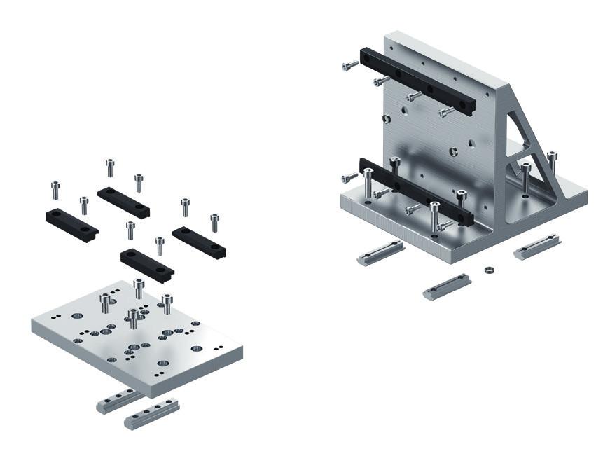
8 8 Connection technology for Linear Motion Systems 1.3 Benefits Connection technology for linear motion systems the fast and easy way to combine electromechanical components cc Angle bracket connection kit cc Plate connection kit The well-thought-out and standardized mechanical interface further enhances the modularity and efficiency of the linear motion system building system. The electromechanical linear motion system components fit perfectly thanks to the positive locking interface. As a result, users can put together complete systems quickly and easily to meet their own specific handling tasks. The innovative locating grid and centering ring technology ensures unrivaled precision and reproducibility when connecting various linear motion systems. In terms of design and scope, the connection element portfolio is optimally adapted to match the components and each specific connecting task, enabling a very broad spectrum of combinations and assembly options. The entire range has been designed to minimize effort every step of the way. The connection elements can also be used with further strut profile accessories to build frames and supporting structures. The linear motion system building system also includes adapters for integrating cable drag chains and guide channels. If desired, systems can also be delivered completely pre-assembled. cc Connection kit


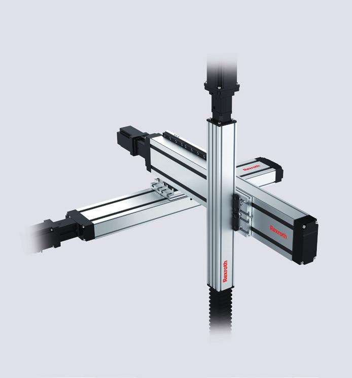
9 Benefits Connection technology for Linear Motion Systems Linear motion system connection technology Build powerful handling systems easily and flexibly with connection technology from Rexroth Advantages: Easy and fast assembly thanks to direct connections or pre-fabricated assemblies Positive-locking and force-fit connections by means of centering elements Optimized execution and shape Weight-optimized Broad spectrum of combination options Benefits: Reduced design and installation effort saves time and money High accuracy, durability, and reproducibility Minimized space requirement and weight, yet high stability and dynamics Flexible thanks to component commonality

 or a 3-dimensional gantry (Part II).")
.")
10 10 Connection technology for Linear Motion Systems 1.3 How to find the connection kit you need How to find the connection kit you need Perfectly combined more than just on direction Define the linear motion system in the product catalogs and find the required connection kit for your desired combination in this catalog. General Information The following examples describe how linear motion systems are connected to a linear gantry (Part I) or a 3-dimensional gantry (Part II). By combining several of these connections, complex multiaxis systems can be built with ease. Installation position The division into -Y and -Z directions in this catalog merely serves as classification criterion (e.g. for the direction of force). The products can be installed in any position. (+) in x-y-direction ( ) M y (+) +F y M z +F z ( ) +F x ( ) M x (+) x-axis Compact Module CKx y-axis Compact Module CKx Compact Module CKx Compact Module CKx F z F x F y in x-z-direction x-axis z-axis Compact Module CKx Omega Module OBB Compact Module CKx Compact Module CKx

 and the intended connection type (-Y, -Z, etc.), certain product features (options) may be required.")
 Y Components Carriage option x-axis MKx Carriage, with")
11 How to find the connection kit you need Connection technology for Linear Motion Systems Selecting the linear motion axis At the beginning of planning a multi-axis combination, suitable individual axes are selected according to the load and application. This is done according to the product catalog of the respective linear motion system. Combining the linear motion axes Based on the selected individual axes (components) and the intended connection type (-Y, -Z, etc.), certain product features (options) may be required. These are specified here in the Connection technology for linear motion systems catalog with the respective connection. Connection technology for linear motion systems catalog Linear Module MKx Linear Module MKx Connection with plate 2-Y (with clamping fixture) Y Components Carriage option x-axis MKx Carriage, with T-slot y-axis MKx any Scope of supply Connection plate, anchor strips, clamping fixtures, socket head cap screws The required product features (options) need to be taken into account when configuring the individual linear motion axes (components). Product catalog "Configuration and ordering Short product name, length MKR-110-NN-2,... mm Guideway Drive Carriage Gear ratio L ca = 210 mm L ca = 305mm Version Drive journal with with with with T-slot thread T-slot thread with gear unit (MG), gear reducer Gear unit right/ left Gear unit right/ left Gear unit with second journal = possible selection

 can be combined. Product catalog Configuration and ordering Short product name, length1) CKK-145-NN-1,.")

12 12 Connection technology for Linear Motion Systems 1.3 How to find the connection kit you need Identifying the connection kit The connection elements therefore need to be identified when selecting the product. The guideway and carriage options are pertinent as these will be connected. Depending on the characteristics of the linear motion axes, both the same options (e.g. carriage on carriage) and different options (e.g. frame on carriage) can be combined. Product catalog Configuration and ordering Short product name, length1) CKK-145-NN-1,... mm Guideway Drive Carriage Standard Center without connection plate with connection plate holes 2) Version Screw journal L ca = 49 mm L ca = 149 mm L ca = variable 3) L ca = 80 mm L ca = 190 mm Without attachment with keyway with keyway = selectable options Connection technology for linear motion systems catalog Linear Module MKx Compact Module CKx Connection via angle brackets 2-Y linear module - carriage with T-slot For this connection, the appropriate order options must be selected when configuring the Compact Modules and Linear Modules, see Compact Modules and Linear Modules catalogs, "Configuration and ordering section. Y Components Guideway option Carriage option x-axis MKx any Carriage with T-slot y-axis CKx mounting-dependent any cc Angle bracket connection kit cc 2-Y connection Scope of supply Connection bracket (material: Al), clamping fixtures (material: Al), screws, centering rings for CKx -200: Connection bracket (material: Al), screws, centering rings, washers, sliding blocks cc CKx -200 adapted with sliding blocks


13 How to find the connection kit you need Connection technology for Linear Motion Systems Easily connected: the interface with centering device The use of standardized centering devices makes it possible to simplify mounting and to reproduce the system mounting in the event of an exchange. For this purpose, centering rings are included in the corresponding connection groups. For the selected linear motion systems, the appropriate options must then be selected in line with the product configuration. Depending on the linear motion system, several options are suitable for the connection and the selection is dependent on the planned mounting. This applies to connections with compact modules, for example. One of the frame options shown below can be used accordingly. Here, the design engineer has all the freedom needed to adapt the product to the intended use. The use of centering rings is optional in terms of load capacity since the technical data for the assembly are determined without them. Product catalog Guideway/carriage options Option 01 /standard Option 03 /with center holes Option 04 /with center holes and long hole Connection technology for linear motion systems catalog Compact Module CKx Compact Module CKx Direct connection -Y (Can also be used as an -Z connection) For this connection, the appropriate order options must be selected when configuring the Compact Modules, see Compact Modules catalog, Configuration and ordering section. Y Carriage travels Components Guideway option Carriage option x-axis CKK, CKR any 41 ( 09 ) y-axis CKK, CKR mounting-dependent 41 ( 09 ) cc Carriage travels cc Frame travels Frame travels Components Guideway option Carriage option x-axis CKK, CKR any 41 y-axis CKK, CKR any 41 cc Clamping fixture connection kit
14 14 Connection technology for Linear Motion Systems 1.3 How to find the connection kit you need Checking the permissible loads of the connection kits After the connection element has been selected, it needs to be checked in terms of its use using the technical data. The coordinate system of the respective version must be observed and, depending on the mounting direction, turned to the actual position in space, if necessary. Connection technology for linear motion systems catalog Load calculation and comparison M x M x max M y M y max M z M z max F x CB F x max F y F y max F z F z max Specify the operating factor CB Specify the operating factor CB according to the following table: Application examples Operating factor CB low dynamics Door guides, guiding of protective enclosures 0.85 medium dynamics Mounting devices 0.65 high dynamics PCB assembly, applications with linear motor 0.50 Permitted values for connection kits Z Z F x max F y max F z max M x max M y max M z max Page Part number x-axis y-axis z-axis (N) (N) (N) (Nm) (Nm) (Nm) 29 R CKx 70 CKx R CKx 90 CKx R CKx 90 CKx R CKx 110 CKx R CKx 110 CKx R CKx 145 CKx R CKx 145 CKx R CKx 200 CKx R CKx 200 CKx


15 How to find the connection kit you need Connection technology for Linear Motion Systems Example of how to identify the right connection kit - Part A Linear gantry as an -Z combination Step 1 Select the system Product catalog configuration and ordering The two CKK-145 and VKK-070 linear motion systems were selected on the basis of the application and load as per the specifications in the respective product catalogs. 1 2 Connection technology for linear motion systems catalog Three configuration options are available for both of the linear motion systems selected. x-axis z-axis Compact Module CKx Feed Module VKK Feed Module VKK Feed Module VKK Selected configuration option The following connection was selected as suitable for the example application Connection kit Direct connection -Z 1 Z x-axis Compact Module CKK 2 Z z-axis Feed Module VKK
16 16 Connection technology for Linear Motion Systems 1.3 How to find the connection kit you need Step 2 Identify the connection kit The appropriate connection kit for the selected combination now needs to be identified. The coordinate system in the configuration diagram indicates which axis is meant in the table. Connection technology for linear motion systems catalog Compact Module CKx Feed Module VKK Direct connection -Z For this connection, the appropriate order options must be selected when configuring the Compact Modules, see Compact Modules catalog, Configuration and Ordering section. Z Components Carriage option x-axis CKK, CKR "41"("09") Scope of supply Clamping fixtures (material: Al), sliding blocks, screws, centering rings Connection kit Profile nominal dimension Compact Module Profile nominal dimension Feed Module Part number m x-axis x-axis z-axis z-axis (kg) 70 CKK/CKR VKK -050 R CKK/CKR VKK -050 R VKK -070 R CKK/CKR VKK -050 R VKK -070 R CKK/CKR VKK -070 R VKK -100 R = selected connection kit


17 How to find the connection kit you need Connection technology for Linear Motion Systems Check component x-axis / CKK-145 The limit conditions of the CKK carriage option are checked here using the Connection technology catalog. Depending on the component, more than one option can be selected here. Depending on the selected drive version - either carriage version 41 or 09 is absolutely necessary for the intended -Z connection. Product catalog Configuration and ordering Short product name, length1) CKK-145-NN-1,... mm Guideway Drive Carriage Standard Center without connection plate with connection plate holes 2) Version Screw journal L ca = 49 mm L ca = 149 mm L ca = variable 3) L ca = 80 mm with keyway with keyway Check component z-axis / VKK-070 The guideway option is pertinent for the connection here. It always comes with center holes as standard. In the Connection technology catalog, there is no specification given because every standard option is suitable. Part number, length R ,... mm Guideway Version with BASA and motor mount with BASA, without motor mount L ca = 190 mm Without attachment = selectable options Product catalog "Configuration and ordering
18 18 Connection technology for Linear Motion Systems 1.3 How to find the connection kit you need Step 3 Check the permissible loads of the connection kits Connection technology for linear motion systems catalog Load calculation and comparison M x M x max M y M y max M z M z max F x CB F x max F y F y max F z F z max Specify the operating factor CB Specify the operating factor CB according to the following table: Application examples Operating factor CB low dynamics Door guides, guiding of protective enclosures 0.85 medium dynamics Mounting devices 0.65 high dynamics Printed circuit board assembly 0.50 Permitted values for connection kits Z F x max F y max F z max M x max M y max M z max Page Part number x-axis y-axis z-axis (N) (N) (N) (Nm) (Nm) (Nm) 29 R CKx 70 VKK R CKx 90 VKK R CKx 90 VKK R CKx 110 VKK R CKx 110 VKK R CKx 145 VKK R CKx 145 VKK = required connection kit


19 How to find the connection kit you need Connection technology for Linear Motion Systems Example II How to identify the right connection kit 3-dimensional gantry as a -Y-Z combination Step 1 Select the system The following linear motion systems were selected on the basis of the application and load as per the specifications in the respective product catalogs: 2x CKK-145 and VKK-070. Product catalog Configuration and ordering The following connection was selected from the available assemblies. 1 Z Y y-axis Compact Module CKK 1) Connection kit via angle bracket 2 Z Y z-axis Feed Module VKK 1) x-axis Compact Module CKK Z Y 3 Connection kit Direct connection 1) 1) These components were already selected/checked in Part A

20 20 Connection technology for Linear Motion Systems 1.3 How to find the connection kit you need Step 2 Identify and check the connection kit The appropriate connection kits for the selected combinations now need to be identified. The coordinate system in the configuration diagram indicates which axes are meant in the table. The two components to be connected must always be considered separately. Selecting and checking the connection kit CKK-145 with CKK-145 Connection technology for linear motion systems catalog Compact Module CKx Compact Module CKx Connection via bracket -Y (reinforced right-hand version) For this connection, the appropriate order options must be selected when configuring the Compact Modules, see Compact Modules catalog, Configuration and Ordering section. Y Components Guideway option Carriage option x-axis CKK, CKR any 41 ( 09 ) y-axis CKK, CKR mounting-dependent any Scope of supply Connection bracket (material: Al), clamping fixtures (material: Al), sliding blocks, screws, centering rings Connection kit Profile nominal dimension Compact Module Profile nominal dimension Compact Module Bracket orientation Part number x-axis x-axis y-axis y-axis 70 CKK/CKR CKK/CKR -070 Right-hand R CKK/CKR CKK/CKR -070 Right-hand R CKK/CKR -090 Right-hand R CKK/CKR CKK/CKR -090 Right-hand R CKK/CKR -110 Right-hand R CKK/CKR CKK/CKR -110 Right-hand R CKK/CKR -145 Right-hand R = selected connection kit In the connection element catalog, the specification for the guideway option is mounting-dependent. Basically, each of the available standard options for the CKK can be used. However, to use the centering devices, option 03 or 04 need to be selected. Here it depends on the application as to which version is appropriate for the planned combination.
21 How to find the connection kit you need Connection technology for Linear Motion Systems Product catalog Connection technology for linear motion systems Option 01 /standard Option 03 /with center holes Option 04 /with center holes and long hole Product catalog Configuration and ordering Short product name, length1) CKK-145-NN-1,... mm Guideway Drive Carriage Standard Center without connection plate with connection plate holes 2) Version Screw journal L ca = 49 mm L ca = 149 mm L ca = variable 3) L ca = 80 mm L ca = 190 mm Without attachment with keyway with keyway = selectable options
22 22 Connection technology for Linear Motion Systems 1.3 How to find the connection kit you need Selecting and checking the connection kit CKK-145 with VKK-070 Connection technology for linear motion systems catalog Compact Module CKx Feed Module VKK Direct connection -Z For this connection, the appropriate order options must be selected when configuring the Compact Modules, see Compact Modules catalog, Configuration and Ordering section. Z Components Carriage option x-axis CKK, CKR 41 ( 09 ) Scope of supply Clamping fixtures (material: Al), sliding blocks, screws, centering rings Connection kit Profile nominal dimension Compact Module Profile nominal dimension Feed Module Part number m x-axis x-axis z-axis z-axis (kg) 70 CKK/CKR VKK -050 R CKK/CKR VKK -050 R VKK -070 R CKK/CKR VKK -050 R VKK -070 R CKK/CKR VKK -070 R VKK -100 R = selected connection kit Only the version of the carriage option for the CKK-145 axis needs to be observed here: Depending on the selected drive version - either carriage version 41 or 09 is absolutely necessary for the intended connection. To conclude, the permissible load for the second connection assembly then needs to be checked
23 How to find the connection kit you need Connection technology for Linear Motion Systems Product catalog Configuration and ordering Short product name, length1) CKK-145-NN-1,... mm Guideway Drive Carriage Standard Center without connection plate with connection plate holes 2) Version Screw journal L ca = 49 mm L ca = 149 mm L ca = variable 3) L ca = 80 mm L ca = 190 mm Without attachment with keyway with keyway = selectable options With regard to the z-axis (VKK-070), no restrictions are made because all versions are permitted. Step 3 Check the permissible loads of the connection kits Load calculation and comparison M x M x max M y M y max M z M z max F x CB F x max F y F y max F z F z max Specify the operating factor CB Specify the operating factor CB according to the following table: Application examples Operating factor CB low dynamics Door guides, guiding of protective enclosures 0.85 medium dynamics Mounting devices 0.65 high dynamics Printed circuit board assembly 0.50 Permitted values for connection kits Y F x max F y max F z max M x max M y max M z max Page Part number x-axis y-axis z-axis (N) (N) (N) (Nm) (Nm) (Nm) 32 R CKx 70 CKx R CKx 90 CKx R CKx 90 CKx R CKx 110 CKx R CKx 110 CKx R CKx 145 CKx R CKx 145 CKx = required connection kit
24 24 Connection technology for Linear Motion Systems 1.3 How to find the connection kit you need CKK-145 with VKK-070 Connection technology for linear motion systems catalog Load calculation and comparison M x M x max M y M y max M z M z max F x CB F x max F y F y max F z F z max Specify the operating factor CB Specify the operating factor CB according to the following table: Application examples Operating factor CB low dynamics Door guides, guiding of protective enclosures 0.85 medium dynamics Mounting devices 0.65 high dynamics Printed circuit board assembly 0.50 Permitted values for connection kits Z F x max F y max F z max M x max M y max M z max Page Part number x-axis y-axis z-axis (N) (N) (N) (Nm) (Nm) (Nm) 29 R CKx 70 VKK R CKx 90 VKK R CKx 90 VKK R CKx 110 VKK R CKx 110 VKK R CKx 145 VKK R CKx 145 VKK = required connection kit
25 Notes Connection technology for Linear Motion Systems Notes Intended Use Linear motion systems and the connection technology for linear motion systems are intended for positioning in space under external loads. The product is intended for professional use and not for private use. Intended use includes having read and understood this documentation, the instructions for the product, the Safety instructions for linear motion systems document, and especially the section Safety instructions. The product is exclusively intended for incorporation into a final machine or system or for assembling with other components to build a final machine or system. Misuse Use of the product in any other way than as described under Intended Use is considered to be misuse and is therefore not permitted. If unsuitable products are installed or used in safety-critical applications, this may lead to uncontrolled operating statuses in the application which can cause personal injury and/or damage to property. The product may only be used in safetycritical applications if this use has been expressly specified and permitted in the product documentation. Bosch Rexroth AG will not accept any liability for injury or damage caused by misuse of the product. The risks associated with any misuse of the product shall be borne by the user alone Misuse of the product includes: the transport of persons General Safety Instructions The safety rules and regulations of the country in which the product is used must be complied with. All current and applicable accident prevention and environmental regulations must be adhered to. The product may only be used when it is in technically perfect condition. The technical data and environmental conditions stated in the product documentation must be complied with. The product must not be put into service until it has been verified that the final product (for example a machine or system) into which the product has been installed complies with the country-specific requirements, safety regulations and standards for the application. The product is never allowed to be disassembled. Excluded from this are the activities described in the product instructions. All notices on the product itself must be complied with. Only use accessories and spare parts approved by the manufacturer. The special safety requirements for specific sectors (e.g. crane construction, theaters, food technology) set forth in laws, directives and standards must be complied with. This also includes, for example, falling loads that pose a potential hazard for people. The following standards must be complied with: DIN 637, ISO 3408 and DIN 69051
26 26 Connection technology for Linear Motion Systems 1.3 Notes Directives and Standards Rexroth linear motion systems are suitable for use in various applications and industries. The various industries must comply with a series of standards and guidelines. These requirements can vary significantly worldwide. It is therefore essential to understand the legislation and standards that apply in each particular region. EN ISO This standard describes the safety of machinery general principles for design, risk assessment and risk reduction. It gives a general overview and contains a guide to the major developments governing machines and their intended use. Directive 2006/42/EC The European Machinery Directive describes the basic safety and health requirements for the design and manufacture of machinery. The manufacturer of a machine or his authorized representative has a duty to ensure that a risk assessment has been performed in order to determine the health and safety requirements which have to be fulfilled for that machine. The machine must be designed and built taking into account the results of the risk assessment. Directive 2001/95/EC This directive covers general safety requirements for any product placed on the market and intended for consumers, or likely to be used by consumers under reasonably foreseeable conditions, including products that are made available to consumers in the context of service provision for use by them Directive 85/374/EEC This directive concerns the liability for defective products and applies to industrially manufactured movable objects, irrespective of whether or not they have been incorporated into another movable or immovable object. Directive 76/769/EEC This directive describes the restrictions on the marketing and use of certain dangerous substances and preparations. Substances means chemical elements and their compounds as they occur in the natural state or as produced by industry. Preparations means mixtures or solutions composed of two or more substances.

 M y (+) M z ( ) +F x ( ) M x ( ) +F y +F z (+) F z F x F y The permissible load values of the connection elements serve as guideline values.")
27 Permissible loads of the connection kits Connection technology for Linear Motion Systems Permissible loads of the connection kits The permissible loads of the individual axes must not be exceeded. This must be checked before selecting the connection kits. In some attachment variations, the permissible loads for the individual axis represent the upper load capability limits. Such connection kits are not listed in the following tables. (+) M y (+) M z ( ) +F x ( ) M x ( ) +F y +F z (+) F z F x F y The permissible load values of the connection elements serve as guideline values. In the case of critical applications or applications with high dynamic loads (> 50% of the permissible loads), the connection kits must be recalculated according to the application requirements. For the external loads of a linear motion axis and the connection kits, not only the process forces but the inertial forces of the products used must always be determined and taken into consideration.


 Screws have been lightly lubricated Friction coefficient µ = 0.")
28 28 Connection technology for Linear Motion Systems 1.3 Permissible loads of the connection kits Define the forces and load moments All external forces and load moments must be referred to the origin of the coordinate system. These values must be specified by the customer. Define the coordinate system The origin of the coordinate system for the calculation of the applied forces and moments lies at the center of the connection element, on the clamping surface of the moved linear axis. Load calculation and comparison M x M x max M y M y max M z M z max F x CB F x max F y F y max F z F z max Specify the operating factor CB Specify the operating factor CB according to the following table: Application examples Operating factor CB low dynamics Door guides, guiding of protective enclosures 0.85 medium dynamics Mounting devices 0.65 high dynamics PCB assembly, applications with linear motor 0.50 Basic principles The permitted values shown in the tables apply under the following conditions: Screws have been tightened using a torque wrench as specified in the table below Mounting screws of strength class 8.8 have been used (are included) Screws have been lightly lubricated Friction coefficient µ = Screw connections have been calculated in accordance with VDI guideline 2230 Tightening torques Screw thread M2 M2.5 M3 M4 M5 M6 M8 M10 M12 Tightening torque (Nm) µ: 0.125; strength class: 8.8 All screws that are not coated with a threadlocking adhesive on delivery must be secured against loosening with a suitable threadlocking adhesive (e.g. Loctite 242).
 (N) (N) (Nm) (Nm) (Nm) 34 R039120227 CKx 90 CKx 70 2 500 20 000")


29 Permissible loads of the connection kits Connection technology for Linear Motion Systems Permitted values for connection kits Z Z F x max F y max F z max M x max M y max M z max Page Part number x-axis y-axis z-axis (N) (N) (N) (Nm) (Nm) (Nm) 34 R CKx 90 CKx R CKx 110 CKx R CKx 145 CKx Z Z 35 R CKx 70 CKx R CKx 90 CKx R CKx 90 CKx R CKx 110 CKx R CKx 110 CKx R CKx 145 CKx R CKx 145 CKx R CKx 200 CKx R CKx 200 CKx Z 38 R CKx 70 VKK R CKx 90 VKK R CKx 90 VKK R CKx 110 VKK R CKx 110 VKK R CKx 145 VKK R CKx 145 VKK Z 39 R CKx 70 VKK R CKx 90 VKK R CKx 90 VKK R CKx 110 VKK R CKx 110 VKK R CKx 145 VKK Z 40 R CKx 70 VKK R CKx 90 VKK R CKx 90 VKK R CKx 110 VKK R CKx 110 VKK R CKx 145 VKK R CKx 145 VKK R CKx 200 VKK Z 42 R CKx 90 OBB R CKx 110 OBB R CKx 145 OBB R CKx 145 OBB R CKx 200 OBB
 (N) (N) (Nm) (Nm) (Nm) 44 R039110060 MKx 80 MKx 65 2 100 2 100 4")
30 30 Connection technology for Linear Motion Systems 1.3 Permissible loads of the connection kits Z F x max F y max F z max M x max M y max M z max Page Part number x-axis y-axis z-axis (N) (N) (N) (Nm) (Nm) (Nm) 44 R MKx 80 MKx R MKx 80 MKx R MKx 110 MKx R MKx 110 MKx R MKx 145 MKx R MKx 165 MKx R MKx 165 MKx Z 45 R MKx 80 MKx R MKx 80 MKx R MKx 110 MKx R MKx 110 MKx R MKx 145 MKx R MKx 165 MKx R MKx 165 MKx Z 43 R OBB -055 VKK R OBB -085 VKK R OBB -120 VKK Y Y Y Y 46 R CKx 70 CKx R CKx 90 CKx R CKx 90 CKx R CKx 110 CKx R CKx 110 CKx R CKx 110 CKx R CKx 145 CKx R CKx 145 CKx R CKx 145 CKx R CKx 200 CKx R CKx 200 CKx R CKx 70 CKx R CKx 90 CKx R CKx 90 CKx R CKx 110 CKx R CKx 90 CKx R CKx 110 CKx R CKx 145 CKx R CKx 110 CKx R CKx 145 CKx R CKx 200 CKx R CKx 200 CKx
31 Permissible loads of the connection kits Connection technology for Linear Motion Systems Z F x max F y max F z max M x max M y max M z max Page Part number x-axis y-axis z-axis (N) (N) (N) (Nm) (Nm) (Nm) 44 R MKx 80 MKx R MKx 80 MKx R MKx 110 MKx R MKx 110 MKx R MKx 145 MKx R MKx 165 MKx R MKx 165 MKx Z 45 R MKx 80 MKx R MKx 80 MKx R MKx 110 MKx R MKx 110 MKx R MKx 145 MKx R MKx 165 MKx R MKx 165 MKx Z 43 R OBB -055 VKK R OBB -085 VKK R OBB -120 VKK Y Y Y Y 46 R CKx 70 CKx R CKx 90 CKx R CKx 90 CKx R CKx 110 CKx R CKx 110 CKx R CKx 110 CKx R CKx 145 CKx R CKx 145 CKx R CKx 145 CKx R CKx 200 CKx R CKx 200 CKx R CKx 70 CKx R CKx 90 CKx R CKx 90 CKx R CKx 110 CKx R CKx 90 CKx R CKx 110 CKx R CKx 145 CKx R CKx 110 CKx R CKx 145 CKx R CKx 200 CKx R CKx 200 CKx ) Carriage with threads 2) Carriage with T-slots
 (N) (N) (Nm) (Nm) (Nm) 50 R039110280 CKx 70 CKx 70 3 300 3 300 5")


 CKx 110 3 400 3 400 4 000 275 970 150 R039110270 MKx 80 1) CKx 145 3 400 3 400 4 000 340 970 150 R039110272 MKx 110 1) CKx 145 5 300 4 000 4 000 340 1 700 280")
 CKx 110 3 500 3 500 4 000 275 810 150 R039110271 MKx 80 2) CKx 145 3 500 3 500 4 000 340 860 150 R039110273 MKx 110 2) CKx 145 6 900 4 000 4 000 340 1 800 390 R039110275 MKx 110 2) CKx 200 6 100 6")
32 32 Connection technology for Linear Motion Systems 1.3 Permissible loads of the connection kits Y F x max F y max F z max M x max M y max M z max Page Part number x-axis y-axis z-axis (N) (N) (N) (Nm) (Nm) (Nm) 50 R CKx 70 CKx R CKx 90 CKx R CKx 90 CKx R CKx 110 CKx R CKx 110 CKx R CKx 145 CKx R CKx 145 CKx Y 51 R CKx 70 CKx R CKx 90 CKx R CKx 90 CKx R CKx 110 CKx R CKx 110 CKx R CKx 145 CKx R CKx 145 CKx Y Y 52 R MKx 40 1) CKx R MKx 40 1) CKx R MKx 65 1) CKx R MKx 65 1) CKx R MKx 80 1) CKx R MKx 80 1) CKx R MKx 110 1) CKx R MKx 110 1) CKx R MKx 65 2) CKx R MKx 65 2) CKx R MKx 80 2) CKx R MKx 80 2) CKx R MKx 110 2) CKx R MKx 110 2) CKx R MKx 165 2) CKx Y 56 R MKx 165 MKx R MKx 110 MKx R MKx 165 MKx R MKx 165 MKx R MKx 80 MKx R MKx 80 MKx R MKx 65 MKx
 (N) (N) (Nm) (Nm) (Nm) 57 R039120000 MKx 165 MKx 165 10 400 10 400 83 500 5 000 2 800 670 R039120002")


33 Permissible loads of the connection kits Connection technology for Linear Motion Systems Y F x max F y max F z max M x max M y max M z max Page Part number x-axis y-axis z-axis (N) (N) (N) (Nm) (Nm) (Nm) 57 R MKx 165 MKx R MKx 165 MKx R MKx 110 MKx R MKx 145 MKx Y Y 58 R TKK 155 TKK R TKK 155 TKK R TKK 225 TKK R TKK 225 TKK R TKK 225 TKK R TKK 225 TKK R TKK 325 TKK R TKK 325 TKK R TKK 325 TKK R TKK 325 TKK R TKK 455 TKK R TKK 455 TKK
34 34 Connection technology for Linear Motion Systems 1.3 Combination options for -Z configurations Compact Module CKx Compact Module CKx End-face connection -Z For this connection, the appropriate order options must be selected when configuring the Compact Modules, see Compact Modules catalog, Components and Ordering section. Z Z Carriage travels Components Guideway option Carriage option x-axis CKK, CKR 03 any z-axis CKK, CKR 03 any cc Carriage travels cc Frame travels Frame travels Components Guideway option Carriage option x-axis CKK, CKR 03 any z-axis CKK, CKR any 41 / 09 Scope of supply Connection plate (material: Al), clamping fixtures (material: Al), screws, centering rings Connection kit Profile nominal dimension Compact Module Profile nominal dimension Compact Module Part number A B C D E F m x-axis x-axis z-axis z-axis (mm) (mm) (mm) (mm) (mm) (mm) (kg) 90 CKK/CKR CKK/CKR -070 R CKK/CKR CKK/CKR -090 R CKK/CKR CKK/CKR -110 R Permissible loads 29 Z C Z Z 1) F 20 E Z B A D 1) Shown without Compact Module
35 Combination options for -Z configurations Connection technology for Linear Motion Systems Compact Module CKx Compact Module CKx Connection via bracket -Z For this connection, the appropriate order options must be selected when configuring the Compact Modules, see Compact Modules catalog, Configuration and Ordering section. Z Z Carriage travels Components Guideway option Carriage option x-axis CKK, CKR any 41 / 09 z-axis CKK, CKR 03 any cc Carriage travels cc Frame travels Frame travels Components Guideway option Carriage option x-axis CKK, CKR any 41 / 09 z-axis CKK, CKR any 41 / 09 Scope of supply Angle bracket (material: Al), clamping fixtures (material: Al), sliding blocks, screws, centering rings Connection kit Profile nominal dimension Compact Module Profile nominal dimension Compact Module Part number x-axis x-axis z-axis z-axis 70 CKK/CKR CKK/CKR -070 R CKK/CKR CKK/CKR -070 R CKK/CKR -090 R CKK/CKR CKK/CKR -090 R CKK/CKR -110 R CKK/CKR CKK/CKR -110 R CKK/CKR -145 R CKK/CKR CKK/CKR -145 R CKK/CKR -200 R Permissible loads 29
36 36 Connection technology for Linear Motion Systems 1.3 Combination options for -Z configurations Frame travels F A D E C D 20 B Profile nominal dimension Profile nominal dimension Part number A B C D E F m x-axis z-axis (mm) (mm) (mm) (mm) (mm) (mm) (kg) R R R R R R R R R
37 D E C 20 D Combination options for -Z configurations Connection technology for Linear Motion Systems Carriage travels F A B Profile nominal dimension Profile nominal dimension Part number A B C D E F m x-axis z-axis (mm) (mm) (mm) (mm) (mm) (mm) (kg) R R R R R R R R R
38 38 Connection technology for Linear Motion Systems 1.3 Combination options for -Z configurations Compact Module CKx Feed Module VKK Direct connection -Z For this connection, the appropriate order options must be selected when configuring the Compact Modules, see Compact Modules catalog, Configuration and Ordering section. Z Components Carriage option x-axis CKK, CKR 41 / 09 Scope of supply Clamping fixtures (material: Al), sliding blocks, screws, centering rings Connection kit Profile nominal dimension Compact Module Profile nominal dimension Feed Module Part number m x-axis x-axis z-axis z-axis (kg) 70 CKK/CKR VKK -050 R CKK/CKR VKK -050 R VKK -070 R CKK/CKR VKK -050 R VKK -070 R CKK/CKR VKK -070 R VKK -100 R Permissible loads 29

, clamping fixtures (material: Al), screws, centering rings Connection kit Profile nominal dimension")
39 F Combination options for -Z configurations Connection technology for Linear Motion Systems Compact Module CKx Feed Module VKK End-face connection -Z For this connection, the appropriate order options must be selected when configuring the Compact Modules, see Compact Modules catalog, Configuration and Ordering section. Z Components Guideway option x-axis CKK, CKR "03" Scope of supply Connection plate (material: Al), clamping fixtures (material: Al), screws, centering rings Connection kit Profile nominal dimension Compact Module Profile nominal dimension Feed Module Part number x-axis x-axis z-axis z-axis 70 CKK/CKR VKK -050 R CKK/CKR VKK -050 R VKK -070 R CKK/CKR VKK -070 R VKK -100 R CKK/CKR VKK -100 R Permissible loads 29 B C Z Z 1) Z A 20 E D Z 1) Shown without Feed Module Profile nominal dimension Profile nominal dimension Part number A B C D E F m x-axis z-axis (mm) (mm) (mm) (mm) (mm) (mm) (kg) R R R R R R

40 40 Connection technology for Linear Motion Systems 1.3 Combination options for -Z configurations Compact Module CKx Feed Module VKK Connection via bracket -Z For this connection, the appropriate order options must be selected when configuring the Compact Modules, see Compact Modules catalog, Configuration and Ordering section. Z Components Carriage option x-axis CKK, CKR 41 / 09 Scope of supply Angle bracket (material: Al), clamping fixtures (material: Al), sliding blocks, screws, centering rings Connection kit Profile nominal dimension Compact Module Profile nominal dimension Feed Module Part number x-axis x-axis z-axis z-axis 70 CKK/CKR VKK -050 R CKK/CKR VKK -050 R VKK -070 R CKK/CKR VKK -050 R VKK -070 R CKK/CKR VKK -070 R VKK -100 R CKK/CKR VKK -100 R Permissible loads 29
41 C 20 D Combination options for -Z configurations Connection technology for Linear Motion Systems F A B D E Profile nominal dimension Profile nominal dimension Part number A B C D E F m x-axis z-axis (mm) (mm) (mm) (mm) (mm) (kg) R R R R R R R R

42 F 42 Connection technology for Linear Motion Systems 1.3 Combination options for -Z configurations Compact Module CKx Omega Module OBB Connection via bracket -Z For this connection, the appropriate order options must be selected when configuring the Compact Modules, see Compact Modules catalog, Configuration and Ordering section. Z Components Carriage option x-axis CKK, CKR 41 Scope of supply Angle bracket (material: Al), sliding blocks, screws, centering rings, straight pins Connection kit Profile nominal dimension Compact Module Profile nominal dimension Omega Module OBB Part number A B C F m x-axis x-axis z-axis z-axis (mm) (mm) (mm) (kg) 90 CKK/CKR OBB -055 R CKK/CKR OBB -055 R CKK/CKR OBB -055 R OBB -085 R CKK/CKR OBB -120 R Permissible loads 29 B A C

 (mm)")

43 Combination options for -Z configurations Connection technology for Linear Motion Systems Omega Module OBB Feed Module VKK Connection via bracket -Z Z Scope of supply End-face plate (material: Al), angle bracket (material: Al), threaded anchor strips, screws, centering rings Connection kit Profile nominal dimension Omega Module Size Feed Module Part number A B C D E m x-axis x-axis z-axis z-axis (mm) (mm) (mm) (mm) (mm) (kg) 55 OBB VKK -050 R OBB VKK -070 R OBB VKK -100 R Permissible loads 30 C D E A B


44 E A 44 Connection technology for Linear Motion Systems 1.3 Combination options for -Z configurations Linear Module MKx Linear Module MKx Connection via bracket -Z Carriage travels Z Linear Module version for x-axis: Carriage with T-slots Scope of supply Angle bracket, threaded anchor strips, clamping fixtures, socket head cap screws cc Carriage travels Connection kit Profile nominal dimension Linear Module Profile nominal dimension Linear Module Part number x-axis x-axis z-axis z-axis 80 MKK/MKR -080, MLR MKK/MKR -065 R MKK/MKR -080, MLR MKK/MKR -110, MLR MKK/MKR -080, MLR -080 R MKK/MKR -110, MLR -110 R MKR MKK/MKR -110, MLR -110 R MKK/MKR MKK/MKR -110, MLR -110 R MKK/MKR -165 R Permissible loads 30 B D C Profile nominal dimension Profile nominal dimension Part number A B C D E m x-axis z-axis (mm) (mm) (mm) (mm) (mm) (kg) R R R R R R


 (mm) (mm) (mm) (kg) 80 65 R039110058 279.0 160.0 120.0 99.5 89.0 2.50 80 R039110059 110 80 R039110054 279.0 160.0 120.0 107.")
45 Combination options for -Z configurations Connection technology for Linear Motion Systems Linear Module MKx Linear Module MKx Connection via bracket -Z Frame travels Z Linear Module version for x-axis and z-axis: Carriage with T-slots Scope of supply Angle bracket, threaded anchor strips, socket head cap screws cc Frame travels Connection kit Profile nominal dimension Linear Module Profile nominal dimension Linear Module Part number x-axis x-axis z-axis z-axis 80 MKK/MKR -080, MLR MKK/MKR -065 R MKK/MKR -080, MLR -080 R MKK/MKR -110, MLR MKK/MKR -080, MLR -080 R MKK/MKR -110, MLR -110 R MKR MKK/MKR -110, MLR -110 R MKK/MKR MKK/MKR -110, MLR -110 R MKK/MKR -165 R Permissible loads 30 C E B D A Profile nominal dimension Profile nominal dimension Part number A B C D E m x-axis z-axis (mm) (mm) (mm) (mm) (kg) R R R R R R R
 For this connection, the appropriate order options must")
46 46 Connection technology for Linear Motion Systems 1.3 Combination options for -Y configurations Compact Module CKx Compact Module CKx Direct connection -Y (Can also be used as an -Z connection) For this connection, the appropriate order options must be selected when configuring the Compact Modules, see Compact Modules catalog, Configuration and Ordering section. Y Y Carriage travels Components Guideway option Carriage option x-axis CKK, CKR any 41 / 09 y-axis CKK, CKR mounting-dependent any cc Carriage travels cc Frame travels Frame travels Components Guideway option Carriage option x-axis CKK, CKR any 41 / 09 y-axis CKK, CKR any 41 / 09 Scope of supply Clamping fixtures (material: Al), sliding blocks, screws, centering rings Connection kit Profile nominal dimension Compact Module Profile nominal dimension Compact Module Part number x-axis x-axis y-axis y-axis 70 CKK/CKR CKK/CKR -070 R CKK/CKR CKK/CKR -070 R CKK/CKR -090 R CKK/CKR CKK/CKR -070 R CKK/CKR -090 R CKK/CKR -110 R CKK/CKR CKK/CKR -090 R CKK/CKR -110 R CKK/CKR -145 R CKK/CKR CKK/CKR -145 R CKK/CKR -200 R Permissible loads 30
47 A A Combination options for -Y configurations Connection technology for Linear Motion Systems Carriage travels Profile nominal dimension Profile nominal dimension Part number A m x-axis y-axis (mm) (kg) R R R R R R R R R R R Frame travels Profile nominal dimension Profile nominal dimension Part number A m x-axis y-axis (mm) (kg) R R R R R R R R R R R
 For this connection, the appropriate order options")


48 48 Connection technology for Linear Motion Systems 1.3 Combination options for -Y configurations Compact Module CKx Compact Module CKx Connection via bracket -Y (Can also be used as an -Z connection) For this connection, the appropriate order options must be selected when configuring the Compact Modules, see Compact Modules catalog, Configuration and Ordering section. Y Y Carriage travels Components Guideway option Carriage option x-axis CKK, CKR any 41 / 09 y-axis CKK, CKR mounting-dependent any cc Carriage travels cc Frame travels Frame travels Components Guideway option Carriage option x-axis CKK, CKR any 41 / 09 y-axis CKK, CKR any 41 / 09 Scope of supply Connection bracket (material: Al), clamping fixtures (material: Al), sliding blocks, screws, centering rings Connection kit Profile nominal dimension Compact Module Profile nominal dimension Compact Module Part number x-axis x-axis y-axis y-axis 70 CKK/CKR CKK/CKR -070 R CKK/CKR CKK/CKR -070 R CKK/CKR -090 R CKK/CKR -110 R CKK/CKR CKK/CKR -090 R CKK/CKR -110 R CKK/CKR -145 R CKK/CKR CKK/CKR -110 R CKK/CKR -145 R CKK/CKR CKK/CKR -145 R CKK/CKR -200 R Permissible loads 30
49 B A Combination options for -Y configurations Connection technology for Linear Motion Systems Carriage travels D 1) D min. 8 G 25 F M (3x) 20 E C 1) Shown without Compact Module Profile nominal dimension Profile nominal dimension Part number A B C D E F G M m x-axis y-axis (mm) (mm) (mm) (mm) (mm) (mm) (mm) (kg) R M R M R M R M R M R M R M R M R M R M R M Frame travels D 1) D A min. 8 G 25 F M (3x) B 20 E C 1) Shown without Compact Module Profile nominal dimension Profile nominal dimension Part number A B C D E F G M m x-axis y-axis (mm) (mm) (mm) (mm) (mm) (mm) (mm) (kg) R M R M R M R M R M R M R M R M R M R M R M6 10.0
 For this connection, the appropriate order options must be")
50 50 Connection technology for Linear Motion Systems 1.3 Combination options for -Y configurations Compact Module CKx Compact Module CKx Connection via bracket -Y (reinforced right-hand version) For this connection, the appropriate order options must be selected when configuring the Compact Modules, see Compact Modules catalog, Configuration and Ordering section. Y Components Guideway option Carriage option x-axis CKK, CKR any 41 / 09 y-axis CKK, CKR mounting-dependent any Scope of supply Connection bracket (material: Al), clamping fixtures (material: Al), sliding blocks, screws, centering rings Connection kit Profile nominal dimension Compact Module Profile nominal dimension Compact Module Bracket orientation Part number x-axis x-axis y-axis y-axis 70 CKK/CKR CKK/CKR -070 Right-hand R CKK/CKR CKK/CKR -070 Right-hand R CKK/CKR -090 Right-hand R CKK/CKR CKK/CKR -090 Right-hand R CKK/CKR -110 Right-hand R CKK/CKR CKK/CKR -110 Right-hand R CKK/CKR -145 Right-hand R Permissible loads 32 Right-hand bracket D min. 8 M (3x) A B 1) 25 H G C E F 1) Shown without Compact Module Profile nominal Profile nominal Part number A B C D E F G H M m dimension x-axis dimension y-axis (mm) (mm) (mm) (mm) (mm) (mm) (mm) (mm) (kg) R M R M R M R M R M R M R M6 4.4
 For this connection, the appropriate order options must be selected when configuring the Compact")
, clamping fixtures (material: Al),")

51 Combination options for -Y configurations Connection technology for Linear Motion Systems Compact Module CKx Compact Module CKx Connection via bracket -Y (reinforced left-hand version) For this connection, the appropriate order options must be selected when configuring the Compact Modules, see Compact Modules catalog, Configuration and Ordering section. Y Components Guideway option Carriage option x-axis CKK, CKR any 41 / 09 y-axis CKK, CKR mounting-dependent any Scope of supply Connection bracket (material: Al), clamping fixtures (material: Al), sliding blocks, screws, centering rings Connection kit Profile nominal dimension Compact Module Profile nominal dimension Compact Module Bracket orientation Part number x-axis x-axis y-axis y-axis 70 CKK/CKR CKK/CKR -070 Left-hand R CKK/CKR CKK/CKR -070 Left-hand R CKK/CKR -090 Left-hand R CKK/CKR CKK/CKR -090 Left-hand R CKK/CKR -110 Left-hand R CKK/CKR CKK/CKR -110 Left-hand R CKK/CKR -145 Left-hand R Permissible loads 32 Left-hand bracket D 1) H 25 G min. 8 8 M (3x) A B C F E 1) without Compact Module Profile nominal Profile nominal Part number A B C D E F G H M m dimension x-axis dimension y-axis (mm) (mm) (mm) (mm) (mm) (mm) (mm) (mm) (kg) R M R M R M R M R M R M R M6 4.4

52 52 Connection technology for Linear Motion Systems 1.3 Combination options for -Y configurations Linear Module MKx Compact Module CKx Connection via brackets 2-Y Linear Module MKx carriage with threads For this connection, the appropriate order options must be selected when configuring the Compact Modules and Linear Modules, see Compact Modules and Linear Modules catalogs, Configuration and Ordering section. Y Components Guideway option Carriage option x-axis MKx any long version, if selectable cc 2-Y connection y-axis CKx 03 / 04 any Scope of supply Connection bracket (material: Al), clamping fixtures (material: Al), screws, centering rings for CKx -200: Connection bracket (material: Al), screws, centering rings, washers, sliding blocks Connection kit c c CKx -200 adapted with sliding blocks Profile nominal dimension Linear Module Profile nominal dimension Compact Module Part number 1) x-axis x-axis y-axis y-axis 40 MKK/MKR CKK/CKR -070 R CKK/CKR -090 R MKK CKK/CKR -090 R CKK/CKR -110 R MKK/MKR CKK/CKR -110 R CKK/CKR -145 R MKR CKK/CKR -145 R CKK/CKR -200 R ) Please order 2 units for 2-Y connections Permissible loads 32
53 B A Combination options for -Y configurations Connection technology for Linear Motion Systems D C 2) D E 2) without Compact Module Profile nominal dimension Profile nominal dimension Part number A B C D E m x-axis y-axis (mm) (mm) (mm) (mm) (mm) (kg) R R R R R R R R

, clamping")
 x-axis x-axis y-axis y-axis 65 MKK/MKR -065 90 CKK/CKR -090 R039110265")
54 54 Connection technology for Linear Motion Systems 1.3 Combination options for -Y configurations Linear Module MKx Compact Module CKx Connection via brackets 2-Y Linear Module MKx - carriage with T-slots For this connection, the appropriate order options must be selected when configuring the Compact Modules and Linear Modules, see Compact Modules and Linear Modules catalogs, Configuration and Ordering section. Y Components Guideway option Carriage option x-axis MKx any long version, if selectable cc 2-Y connection y-axis CKx mounting-dependent any Scope of supply Connection bracket (material: Al), clamping fixtures (material: Al), screws, centering rings, washers, sliding blocks for CKx -200: Connection bracket (material: Al), screws, centering rings, washers, sliding blocks cc CKx -200 adapted with sliding blocks Connection kit Profile nominal dimension Linear Module Profile nominal dimension Compact Module Part number 1) x-axis x-axis y-axis y-axis 65 MKK/MKR CKK/CKR -090 R CKK/CKR -110 R MKK/MKR -080, MLR CKK/CKR -110 R CKK/CKR -145 R MKK/MKR -110, MLR CKK/CKR -145 R CKK/CKR -200 R MKK/MKR CKK/CKR -200 R ) Please order 2 units for 2-Y connections Permissible loads 32
55 B A Combination options for -Y configurations Connection technology for Linear Motion Systems D C 2) D E 2) without Compact Module Profile nominal dimension Profile nominal dimension Part number A B C D E m x-axis y-axis (mm) (mm) (mm) (mm) (mm) (kg) R R R R R R R
 Y Components Carriage option x-axis MKx Carriage, with T-slot y-axis")
56 56 Connection technology for Linear Motion Systems 1.3 Combination options for -Y configurations Linear Module MKx Linear Module MKx Connection with plate 2-Y (with clamping fixture) Y Components Carriage option x-axis MKx Carriage, with T-slot y-axis MKx any Scope of supply Connection plate, anchor strips, clamping fixtures, socket head cap screws Connection kit Profile nominal dimension Linear Module Profile nominal dimension Linear Module Part number 1) A B C m x-axis x-axis y-axis y-axis (mm) (mm) (mm) (kg) 65 MKK/MKR MKK/MKR -065 R MKK/MKR -080, 65 MKK/MKR -065 R MLR MKK/MKR -080, MLR -080 R MKK/MKR -110, MLR MKK/MKR -080, MLR -080 R MKK/MKR MKK/MKR -110, MLR -110 R MKR -145 R MKK/MKR -165 R ) Please order 2 units for 2-Y connections Permissible loads 32 A A A C A A B
 Y Components Carriage option x-axis MKx Carriage, with T-slot y-axis MKx any Scope of supply Connection")
 (mm) (mm) (kg) 110 MKK/MKR -110, MLR -110 110 MKK/MKR -110, MLR -110 R039120003 18.0 138.0 220.0 1.50 145 MKR -145 110 R039120055 25.0 230.0 360.0 5.60 165 MKK/MKR -165 110 R039120002 25.0 163.")
57 Combination options for -Y configurations Connection technology for Linear Motion Systems Linear Module MKx Linear Module MKx Connection with plate 2-Y (without clamping fixture) Y Components Carriage option x-axis MKx Carriage, with T-slot y-axis MKx any Scope of supply Connection plate, threaded anchor strips, socket head cap screws Connection kit Profile nominal dimension Linear Module Profile nominal dimension Linear Module Part number 1) A B C m x-axis x-axis y-axis y-axis (mm) (mm) (mm) (kg) 110 MKK/MKR -110, MLR MKK/MKR -110, MLR -110 R MKR R MKK/MKR R MKK/MKR -165 R ) Please order 2 units for 2-Y connections Permissible loads 33 A A A C A A B
 Y Y For this connection the appropriate order")


58 58 Connection technology for Linear Motion Systems 1.3 Combination options for -Y configurations Ball Rail Table TKK Ball Rail Table TKK Connection with plate -Y (Can also be used as an -Z connection) Y Y For this connection the appropriate order options must be selected when configuring the Ball Rail Tables, see Ball Rail Tables catalog, Configuration and ordering section. Guideway option Carriage option Carriage travels y-axis flat version any Frame travels y-axis any long version cc Carriage travels cc Frame travels Scope of supply Cross-plate, straight pins, socket head cap screws, slotted nuts Connection kit Profile nominal dimension Ball Rail Table Profile nominal dimension Ball Rail Table Part number Connection type x-axis x-axis y-axis y-axis 155 TKK AL 155 TKK AL R Carriage travels 155 TKK AL R Frame travels 225 TKK AL 155 TKK AL R Carriage travels 155 TKK AL R Frame travels 225 TKK AL R Carriage travels 225 TKK AL R Frame travels 325 TKK AL 225 TKK AL R Carriage travels 225 TKK AL R Frame travels 325 TKK AL R Carriage travels 325 TKK AL R Frame travels 455 TKK AL 325 TKK AL R Carriage travels 325 TKK AL R Frame travels Permissible loads 33
59 Combination options for -Y configurations Connection technology for Linear Motion Systems G A C B C E F D Profile nominal dimension Profile nominal dimension Part number A B C D E F G m x-axis y-axis (mm) (mm) (mm) (mm) (mm) (mm) (mm) (kg) R R R R R R R R R R R R

60 60 EasyHandling Connection Technology 1.3 Combination options with profiles Combination options with profiles Rexroth offers multiple options for fastening axis systems to a base frame. Strut profiles for constructing all kinds of frames, feet for simple fastening to the base frame


 Compatible")


61 Combination options with profiles Connection technology for Linear Motion Systems End-face attachment of the linear motion system Side mounting of the linear motion system Strut profile: Space-saving and rigid design Positive-locking connection (centering rings) Compatible with Basic Mechanical Elements (MGE) from Rexroth, profile size PB 30 and PB 45 Foot: Simple connection of strut profile to base frame Positive-locking connection (centering rings) Compatible with Basic Mechanical Elements (MGE) from Rexroth, profile size PB 30, PB 40 and PB 45 Connection kit: Direct mounting Positive-locking connection (centering rings) No alignment necessary minimized installation effort


62 62 Connection technology for Linear Motion Systems 1.3 Combination options with profiles Strut profiles 60 x 60, 90 x 90 Aluminum profile, clear anodized Space-saving and rigid design Standardized modular dimensions/spacing Positive-locking connection (centering rings) Compatible with Basic Mechanical Elements (MGE) from Rexroth 40 ±0,01 A - A 40 ±0,01 A - A N x 40 A A L ± N x 40 A A 6 L ± ±0, ,1 10 Ø9 H ±0, ,1 Ø12 H cc Strut profile size 60 x cc Strut profile size 90 x 90 1 for sliding block 10 mm 2 for sliding block 8 mm Strut profile Profile nominal dimension Part number Length m Planar moment of inertia l x = l y Strut profile L max (mm) variable (kg) (kg/m) (cm 4 ) 60 x R R x 90 R R
 from Rexroth, profile size PB 20 and PB 40 Scope of supply Foot")
 R037530013 0.")
63 Combination options with profiles Connection technology for Linear Motion Systems Foot for profile size 60 x 60 Simple connection of strut profile to base frame Compatible with Basic Mechanical Elements (MGE) from Rexroth, profile size PB 20 and PB 40 Scope of supply Foot angle bracket (material: Al), sliding blocks, screws, centering rings Ø5,5 Ø9 H7 40 ±0,01 Ø12 H ±0, , ±0, Ø12 H7 40 Ø5,5 Ø9 H ±0.01 Part number m (kg) R Foot for profile size 90 x 90 Simple connection of strut profile to base frame Compatible with Basic Mechanical Elements (MGE) from Rexroth, profile size PB 40 and PB 45 Scope of supply Foot angle bracket (material: Al), sliding blocks, screws, centering rings Part number m (kg) R


64 64 Connection technology for Linear Motion Systems 1.3 Combination options with profiles Foot (with webs), adjustable version Simple connection of strut profile to base frame. Adjustable in one axial direction. The base of the adjustable foot can be aligned in one axial direction. The foot has a groove milled along the centerline of its base (8 H8 for profile 60 x 60 and 10 H8 for profile 90 x 90). The groove has been widened at each end and provided with threads. Using the pins provided, the foot can be aligned to any required elements at the installation location, such as a key or locating pin. Scope of supply Foot (material: Al), sliding blocks, screws, centering rings R R Ø12 H7 Ø9 H H ,6 H13 38,5 51, H H Foot Part number m (kg) For profile 60 x 60 R For profile 90 x 90 R
 No alignment necessary")

, sliding blocks, screws, centering rings cc Compact")

65 Combination options with profiles Connection technology for Linear Motion Systems Strut Profile Linear Motion System Direct connection Side mounting of modules Direct mounting Positive-locking connection (centering rings) No alignment necessary Minimizes installation effort For this connection, the appropriate order options must be selected when configuring the Compact Modules, see Compact Modules catalog, Configuration and Ordering section. cc Feed Module VKK cc Compact Module CKx Carriage travels Carriage travels Components Guideway option Carriage option CKK, CKR mounting-dependent any Frame travels Components Guideway option Carriage option CKK, CKR any 41 / 09 Scope of supply Clamping fixtures (material: Al), sliding blocks, screws, centering rings cc Compact Module CKx Frame travels cc Linear Module MKx Connection kit Profile nominal dimension, linear motion system Linear motion system Profile nominal dimension, profile Profile Part number 40 MKK/MKR Strut profile 60 R VKK Strut profile 60 R CKK/CKR Strut profile 60 R VKK Strut profile 90 R CKK/CKR Strut profile 60 R Strut profile 90 R VKK Strut profile 90 R CKK/CKR Strut profile 90 R CKK/CKR Strut profile 90 R


,")
66 66 Connection technology for Linear Motion Systems 1.3 Combination options with profiles Strut Profile Linear Motion System End-face connection Positive-locking connection (centering rings) No alignment necessary Minimizes installation effort For this connection, the appropriate order options must be selected when configuring the Compact Modules, see Compact Modules catalog, Configuration and Ordering section. cc Carriage travels cc Frame travels Carriage travels Components Guideway option Carriage option CKK, CKR mounting-dependent any Frame travels Components Guideway option Carriage option CKK, CKR any 41 / 09 Scope of supply Plate (material: Al), angle bracket, clamping fixtures (material: Al), sliding blocks, screws, centering rings
67 Combination options with profiles Connection technology for Linear Motion Systems C B A D E Connection kit Profile nominal Linear motion system Profile nominal Strut profile Part number A B C D E m dimension dimension (mm) (mm) (mm) (mm) (mm) (kg) 40 MKK/MKR R min. 7/max R min. 9/max VKK R min. 7/max R min. 9/max CKK/CKR R min. 7/max R min. 9/max VKK R min. 7/max R min. 9/max CKK/CKR R min. 7/max R min. 9/max VKK R min. 9/max CKK/CKR R min. 9/max CKK/CKR R min. 9/max
 Linear Motion System Direct connection Designed for aluminum profiles from the MGE range with a modular dimension of 40 and 50 mm")

68 68 Connection technology for Linear Motion Systems 1.3 Combination options with profiles MGE (Basic Mechanical Elements) Linear Motion System Direct connection Designed for aluminum profiles from the MGE range with a modular dimension of 40 and 50 mm and a 10 mm T-slot For this connection, the appropriate order options must be selected when configuring the Compact Modules, see Compact Modules catalog, Configuration and Ordering section. cc Carriage travels cc Frame travels Carriage travels Components Guideway option Carriage option CKK, CKR mounting-dependent any Frame travels Components Guideway option Carriage option CKK, CKR any 41 / 09 Scope of supply Clamping fixtures (material: Al), screws, sliding blocks Connection kit Profile nominal dimension Linear motion system Profile nominal dimension Profile Part number 40 MKK/MKR MGE profile 40 R VKK MGE profile 40 R MKK/MKR MGE profile 50 R VKK MGE profile 40 R MGE profile 50 R CKK/CKR MGE profile 40 R MKK/MKR MGE profile 40 R MLR MGE profile 50 R CKK/CKR MGE profile 40 R MGE profile 50 R VKK MGE profile 40 R MGE profile 50 R CKK/CKR MGE profile 40 R MGE profile 50 R MKK/MKR MGE profile 40 R MLR MGE profile 50 R CKK/CKR MGE profile 40 R MGE profile 50 R MKK/MKR MGE profile 50 R MKK/MKR MGE profile 50 R
 Linear Motion System Connection via plate Designed for aluminum profiles from the MGE range with a modular dimension of 40, 45 and 50 mm and a 10 mm T-slot For")

 (mm) (mm) (kg) 70 CKK/CKR -070, MKK/MKR -040, VKK -050 40 MGE profile 40 R039120237 90 115 16 0.")
69 A Combination options with profiles Connection technology for Linear Motion Systems MGE (Basic Mechanical Elements) Linear Motion System Connection via plate Designed for aluminum profiles from the MGE range with a modular dimension of 40, 45 and 50 mm and a 10 mm T-slot For this connection, the appropriate order options must be selected when configuring the Compact Modules, see Compact Modules catalog, Configuration and Ordering section. cc Carriage travels cc Frame travels Carriage travels Components Guideway option Carriage option CKK, CKR mounting-dependent any Frame travels Components Guideway option Carriage option CKK, CKR any 41 / 09 Scope of supply Plate (material: Al), clamping fixtures (material: Al), screws, sliding blocks, centering rings C B Profile nominal dimension Linear motion system Profile nominal dimension Profile Part number A B C m (mm) (mm) (mm) (kg) 70 CKK/CKR -070, MKK/MKR -040, VKK MGE profile 40 R MGE profile MGE profile CKK/CKR MGE profile 40 R MGE profile MGE profile CKK/CKR -110, VKK MGE profile 40 R MGE profile MGE profile CKK/CKR -145, VKK MGE profile 40 R MGE profile MGE profile 50

70 70 EasyHandling Connection Technology 1.3 Cable drag chains Cable drag chains Rexroth offers a complete system solution to cover many applications areas: Cable drag chains, guide channels, and clamping profiles that can be combined at will to produce the desired configuration.


71 Cable drag chains Connection technology for Linear Motion Systems Cable drag chains, System MP in ESD design Cable drag chains in 2 types with 3 sizes each Pre-tensioned Suitable for self-supporting installation Generally ESD-compatible Different number of separators, depending on the size Chain brackets complete with screws and sliding blocks Guide channels in corrosion-resistant steel sheet cc Clamping profiles cc Cable drag chains cc Guide channels for cable drag chains
 L L = multiple of 33 mm pitch Cable drag chain Part number")
72 72 Connection technology for Linear Motion Systems 1.3 Cable drag chains Cable drag chain System MP18.2 Radius 78 mm Pitch 33 mm Separators are installed at every 2nd chain link Ordering data: R , 825 mm (25 chain links of 33 mm each) L L = multiple of 33 mm pitch Cable drag chain Part number No. of separators Type B b x h Ød Every 2nd chain link (mm) (mm) (mm) ESD-MP x 18 max. 15 R ESD-MP x 18 max. 15 R ESD-MP x 18 max. 15 R Technical specifications Travel distance, gliding L g not recommended Travel distance, self-supporting L f see diagram Travel distance, vertical, hanging L vh 8.0 m Travel distance, vertical, upright L vs 3.0 m Rotated 90, unsupported L 90f 0.5 m 23 h Ød Speed, unsupported V f 5.0 m/s Acceleration, unsupported a f 5.0 m/s 2 b Loading side: Inside flexure curve B Separator Type T I (mm) TR14/ T I Installation dimensions Dimensions (mm) Radius R 78 Height of chain link H G 23 Height of bend H 179 Height of moving end connection H MA 156 Safety margin S 30 H MA F L R L B H S H S Installation height H S 209 Arc projection M L 123 H G Bend length L B 314 M L
 L Cable drag chain Part number No. of separators Type B (mm) b x h (mm) Ød (mm) Every 2nd chain link ESD-MP3002 55 37 x 26 max.")
73 Cable drag chains Connection technology for Linear Motion Systems Cable drag chain System MP3000 Radius 70 mm Pitch 45 mm Separators are installed at every 2nd chain link. Ordering data: R , 990 mm (22 chain links of 45 mm each) L Cable drag chain Part number No. of separators Type B (mm) b x h (mm) Ød (mm) Every 2nd chain link ESD-MP x 26 max. 23 R ESD-MP x 26 max. 23 R ESD-MP x 26 max. 23 R Technical specifications Travel distance, gliding L g 60 m Travel distance, self-supporting L f see diagram Travel distance, vertical, hanging L vh 40 m Travel distance, vertical, upright L vs 3 m Rotated 90, unsupported L 90f 0.7 m 36 h Ød Speed, gliding V g 3 m/s Speed, unsupported V f 6 m/s b Acceleration, gliding a g 10 m/s 2 B Acceleration, unsupported a f 15 m/s 2 Loading side: Inside flexure curve Separator Type T I H H 1 H 2 (mm) (mm) (mm) (mm) TR H 2 H 1 T I H Installation dimensions Dimensions (mm) Radius R 70 Height of chain link H G 35 Height of bend H 175 Height of moving end connection H MA 140 Safety margin with bias S V 45 H MA F L R L B H S K, S V H SV, H SK Installation height with bias H SV 220 Safety margin without bias S K 10 H G Installation height without bias H SK 185 Arc projection M L 133 M L Bend length L B 320
 MP18025 MP18050/18070 Scope of supply 1 piece with")


74 74 Connection technology for Linear Motion Systems 1.3 Cable drag chains Chain bracket (included with the cable drag chain) MP18025 MP18050/18070 Scope of supply 1 piece with bore, 1 piece with pivot pin screws and sliding blocks The chain brackets must be fastened using the included screws. The cables or hoses must be fixed to the chain bracket s integrated strain relief using cable binders. MP3000 Chain type Chain bracket A B C D E F G (mm) (mm) (mm) (mm) (mm) (mm) (mm) MP18025 KA/Z Ø 5.5 MP18050 KA/Z Ø 5.5 MP18070 KA/Z Ø 5.5 MP3002 KA/Z Ø MP3003 KA/Z Ø MP3005 KA/Z Ø

75 Cable drag chains Connection technology for Linear Motion Systems Technical data Unsupported length F Lg : Ideal installation situation for high loads at the limit of the max. travel parameters. In this range the chain upper run is still biased, straight or has a max. sag of mm depending on the type of chain. F Lb : Satisfactory installation position for many applications working in the lower to middle range of the max. travel parameters. Depending on the chain type, the sag of the chain upper run is > mm but less than the max. sag. If the sag is greater than F Lb, the arrangement is unsuitable and should be avoided. Please choose a more stable cable drag chain. MP , ,5 1,0 1,5 2,0 2,5 3,0 2 1 Load (kg/m) 2 Self-supporting length (m) MP F Lg F Lb 1 0, ,5 1,0 1,5 2,0 2,5 3,0 2 Determining the chain length The fixed point of the cable drag chain should be connected in the middle of the travel distance. This arrangement gives the shortest connection between the fixed point and the moving consumer and thus the most efficient chain length. L L/2 L/2 T E R L L K = 2 MP18.2: MP3000: + p R + 2 T + E ~ 1 m chain: 30 x 33 mm links ~ 1 m chain: 22 x 45 mm links L K = Chain length (mm) L = Travel distance (mm) R = Radius (mm) T = Pitch (mm) E = Distance between entry point and middle of travel distance (mm)

76 A 76 Connection technology for Linear Motion Systems 1.3 Cable drag chains Guide channels For cable drag chains The guide channels are matched to the cable drag chains. For short travel distances they serve as a support for stacking the links and for long travel distances they also serves as guides. To minimize chain wear, stainless steel sheet was chosen as the material for the guide channels. The mounting holes for the chain bracket are already integrated in the guide channel. The guide channel has holes drilled at 500 mm intervals along the centerline for M5 countersunk screws. It comes complete with the necessary countersunk screws and sliding blocks. 1 ØF 1, N x 500 E D D 90 Ø10,4 ØF E B L (max. L 4000) C Version for chain type: 1 MP MP18050, MP18070, MP3002, MP3003, MP3005 Chain type Guide channel A B C D E F Part number (variable length) (mm) (mm) (mm) (mm) (mm) (mm) MP18025 Chain guide for MP Ø 5.5 R MP18050 Chain guide for MP Ø 5.5 R MP18070 Chain guide for MP Ø 5.5 R MP3002 Chain guide for MP Ø 6.6 R MP3003 Chain guide for MP Ø 6.6 R MP3005 Chain guide for MP Ø 6.6 R


, Screw DIN 7500 M5x25 (2x)")

 12x40 200 R039170012 0.18 R039170013 0.")

77 Cable drag chains Connection technology for Linear Motion Systems Attachment of cable drag chains The following standardized interfaces were designed to facilitate connection of the cable drag chain or guide channel in a variety of ways. By combining these standard elements, it is possible to accommodate almost any desired connection configuration. Cable drag chain node point Scope of supply Profile (1x), socket head cap screws M6 (2x), sliding block M6 (2x), Screw DIN 7500 M5x25 (2x) cc Attachment of cable drag chains c c Attachment of cable drag chain with guide channel Profile Length Part number m (mm) (mm) Variable (kg) (kg/m) 12x R R ,5 ±0,2 6 1 For self-tapping screws M Ø6,6 H13 25 ±0,15 1 L Examples 3 2 Any standard small parts not used must be disposed of appropriately! 2 Screws M6x20, sliding blocks N8M6 3 Screws DIN7500 M5x25

 1 2 1 Attachment to the connection plate Linear motion")


78 78 Connection technology for Linear Motion Systems 1.3 Cable drag chains Linear motion system node point Scope of supply Clamping profile (1x), countersunk screws per DIN 7500 M5 (2x), set screws (4x) Attachment to the connection plate Linear motion system Profile nominal Part number dimension CKK/CKR 70 R R R R Attachment to the frame Linear motion system Profile nominal Part number dimension CKK/CKR 70 R R R VKK 50 R R R MKK/MKR 40 R Examples


 Part number m (kg)")
79 Cable drag chains Connection technology for Linear Motion Systems VKK node point Scope of supply Split clamp, screws (2x) Part number m (kg) R Examples


, sliding blocks")
80 80 Connection technology for Linear Motion Systems 1.3 Cable drag chains Angle node point The threads in the end face are spaced so that the profile can be attached using the included screws without any further preparation. Angle bracket node point Scope of supply Bracket (1x), countersunk screws M5 (2x) Part number R Strut node point Scope of supply Clamping profile (1x), socket head cap screws (2x), sliding blocks (2x), countersunk screws M5 per DIN 7500 (2x) Strut profile Part number 60 R R Examples


81 Cable drag chains Connection technology for Linear Motion Systems Ordering examples 1x guide channel R , 385 mm 2x profiles R x clamping profiles R x cable drag chain R , 792 mm 2x profiles R x profile R , 250 mm 1x clamping profile R x bracket R x profiles R x clamping profiles R x guide channel R , 380 mm 1x cable drag chain R , 990 mm

82 82 Connection technology for Linear Motion Systems 1.3 Permissible loads EasyHandling Easier. Faster. More Economical. Easier to get results that fit Tailor-made solutions just like that with support all the way. Faster route to your ideal application Effortless adaptation, even to future requirements fast and flexible scalability. More economical thanks to built-in efficiency Optimizes processes from planning through to operation with significant savings on resources. Planning up to 70% faster EasyHandling tools help users right from the component selection stage by proposing solutions with all the necessary information on parts lists, technical data and CAD drawings. Installation saves up to 60% on time Thanks to positive-locking interfaces, the mechanical components are perfectly aligned and accurately connected right away. Start-up reduces your effort by up to 90% With the smart start-up assistant EasyWizard, parameterization and configuration take no time at all. Your handling system will be ready to go in just a few clicks. Production more economical and more efficient Rexroth enhances the system effectiveness still further with smart application tools: The drive controller software sends maintenance-related messages to the user based on operating hours and travel to help schedule servicing at the right intervals. The result: longer life and reduced risk of failure. Future developments continuous improvement Prepare now for future market developments: One of the great features of EasyHandling systems is their openness. The flexibility of the mechanical and electrical components allows you to adapt quickly and efficiently to new production requirements.


83 Permissible loads Connection technology for Linear Motion Systems EasyHandling more than just a building system The modular system concept for perfect scalability basic made-to-measure mechanics EasyHandling basic includes all mechatronic components for complete, custom single and multiaxis linear motion systems. All of the component interfaces are systematically standardized, making it possible to combine them with ease. Practical tools and aids make selection and configuration even easier. comfort get off to a faster start EasyHandling comfort expands the basic component range by adding powerful servo drives with multiple protocol capability. The universal, smart control units are ideally suited for a variety of handling tasks. Unique: with the EasyWizard start-up assistant, linear motion systems are ready to use after entering just a few product-specific parameters. EasyHandling basic EasyHandling comfort advanced controls for demanding requirements With its individually scalable, high-performance Motion Logic solution, EasyHandling advanced makes configuration and handling even easier. Predefined functions covering more than 90 percent of all handling applications eliminate the need for lengthy programming. EasyHandling advanced
camoline Cartesian Motion Building System R310EN 2605 ( )
") camoline Cartesian Motion Building System R310EN 2605 (2009.08) The Drive & Control Company Modularity for best effectiveness Efficient Handling Solutions more than just a system Bosch Rexroth AG 2 Our
camoline Cartesian Motion Building System R310EN 2605 (2009.08) The Drive & Control Company Modularity for best effectiveness Efficient Handling Solutions more than just a system Bosch Rexroth AG 2 Our
Ball Rail Systems BSCL. Ball Runner Blocks, Ball Guide Rails, accessories
 Ball Rail Systems BSCL Ball Runner Blocks, Ball Guide Rails, accessories 2 Ball Rail Systems BSCL General product information The Ball Rail System Compact Line BSCL The new Ball Rail System BSCL (Ball
Screw Assemblies. Ball Screw Assemblies BASA Planetary Screw Assemblies PLSA
 Screw Assemblies Ball Screw Assemblies BASA Planetary Screw Assemblies PLSA 2 Screw Assemblies Ball Screw Assemblies BASA Ball screw assemblies are the efficient solution for precise conversion of rotary
Screw Assemblies. Ball Screw Assemblies BASA Planetary Screw Assemblies PLSA
 Screw Assemblies Ball Screw Assemblies BASA Planetary Screw Assemblies PLSA 2 Screw Assemblies Ball Screw Assemblies BASA Ball Screw Assemblies are the efficient solution for the precise conversion of
Precision Modules PSK
 Precision Modules PSK 2 Bosch Rexroth AG Precision Modules PSK R999000500 (2015-12) Identification system for short product names Short product name Example:: P S K - 050 - N N - 1 System = Precision Module
Product Description. Characteristic features R310A 2402 ( ) Linear Modules MLR
 Linear Modules MLR") 9 Bosch Rexroth Corporation R310A 40 (1.11) MLR Product Description Characteristic features MLR...: with Cam Roller Guide and Toothed Belt Drive for high-speed applications (up to 10 m/s) with Cam Roller
9 Bosch Rexroth Corporation R310A 40 (1.11) MLR Product Description Characteristic features MLR...: with Cam Roller Guide and Toothed Belt Drive for high-speed applications (up to 10 m/s) with Cam Roller
Linear Motion Technology Handbook. The Drive & Control Company
 Linear Motion Technology Handbook The Drive & Control Company 1-2 Bosch Rexroth AG Linear Motion Technology Handbook R310EN 2017 (2006.07) Linear Motion and Assembly Technologies www.boschrexroth.com/brl
EMC-HD. C 01_2 Subheadline_15pt/7.2mm
 C Electromechanical 01_1 Headline_36pt/14.4mm Cylinder EMC-HD C 01_2 Subheadline_15pt/7.2mm 2 Elektromechanischer Zylinder EMC-HD Short product name Example: EMC 085 HD 1 System = ElectroMechanical Cylinder
Compact Modules. with ball screw drive and toothed belt drive R310EN 2602 ( ) The Drive & Control Company
 The Drive & Control Company") with ball screw drive and toothed belt drive R310EN 2602 (2007.02) The Drive & Control Company Bosch Rexroth AG Linear Motion and Assembly Technologies Ball Rail Systems Roller Rail Systems Linear Bushings
with ball screw drive and toothed belt drive R310EN 2602 (2007.02) The Drive & Control Company Bosch Rexroth AG Linear Motion and Assembly Technologies Ball Rail Systems Roller Rail Systems Linear Bushings
C 01_1 Headline_36pt/14.4mm
 Compact Modules C 01_1 Headline_36pt/14.4mm Catalog addition: Lubrication / Cover Resist C 01_2 Subheadline_15pt/7.2mm 2 Compact Modules - catalog addition Identification system for short product names
Efficient Handling Solutions. Solutions for handling applications from Rexroth
 Solutions for handling applications from Rexroth 2 3 The efficient route to best results Whatever you want to automate, we will find the most appropriate solution for each specific application. Our experiences
CKR Compact Modules with Ball Rail Guides and Toothed Belt Drive. The Drive and Control Company
 CKR Compact Modules with Ball Rail Guides and Toothed Belt Drive The Drive and Control Company Bosch Rexroth Corp. Linear Motion and Assembly Technologies CKR RE 8 615 (03.006) Rexroth Linear Motion Technology
Screw Assemblies. Ball Screw Assemblies BASA Planetary Screw Assemblies PLSA
 Screw Assemblies Ball Screw Assemblies BASA Planetary Screw Assemblies PLSA 2 Screw Assemblies Ball Screw Assemblies BASA Ball Screw Assemblies are the efficient solution for the precise conversion of
Precision Modules PSK
 Precision Modules PSK The Drive & Control Company Rexroth Linear Motion Technology Ball Rail Systems Roller Rail Systems Standard Ball Rail Systems Super Ball Rail Systems Ball Rail Systems with Aluminum
Ball rail systems. Ball runner blocks, ball rails, accessories
 Ball rail systems Ball runner blocks, ball rails, accessories Printed catalogs are available from the end of February 2015 2 Ball rail systems Table of contents General product information 4 New features
Contents. Page. 1. Product description. 2. The AXC line of linear axes. 3. AXLT line of linear tables. AXC and AXS product overview...
 SNR Industry Contents Page 3 1. Product description AXC and AXS product overview... 6-8 Dynamic load ratings of the linear motion systems... 9 Compact modules... 10-11 Linear tables... 12 Telescopic axes...
Omega Modules OBB R310EN 2407 ( )N. The Drive & Control Company
N. The Drive & Control Company") Omega Modules OBB R310EN 2407 (2011-09)N The Drive & Control Company The ideal system solution for the ideal application EasyHandling Basic Comfort Advanced Mechanical and pneumatic components, grippers,
Omega Modules OBB R310EN 2407 (2011-09)N The Drive & Control Company The ideal system solution for the ideal application EasyHandling Basic Comfort Advanced Mechanical and pneumatic components, grippers,
Compact Modules CKK/CKR 9-70
 Compact Modules CKK/CKR 9-70 (with Ball Rail System, Ball Screw Drive or Toothed Belt Drive) R310EN 2624 (2008.10) The Drive & Control Company Bosch Rexroth AG Linear Motion and Assembly Technologies Ball
Precision Modules PSK. The Drive & Control Company
 Precision Modules PSK The Drive & Control Company 2 Bosch Rexroth Coporation Precision Modules PSK R310A 2414 (2008.07) Linear Motion and Assembly Technologies Ball Rail Systems Roller Rail Systems Linear
Miniature Linear Modules MKK/MKR The Drive & Control Company
 Miniature Linear Modules MKK/MKR 12-40 The Drive & Control Company 2 Miniature Linear Modules R310A 2418 (2009.05) Linear Motion and Assembly Technologies Ball Rail Systems Roller Rail Systems Linear Bushings
Service - Safety Manual
 Service - Safety Manual Mounting and maintenance instructions Linear Units LT50 series Code Unit Serial number Date by Linear Units LT50 series Table of contents 1 Safety 3 1.1 Significance of the manual
Miniature Ball Rail Systems
 R310EN 2210 (2004.06) The Drive & Control Company 2 Bosch Rexroth AG Linear Motion and Assembly Technologies Miniature-BRS R310EN 2210 (2004.06) Linear Motion Systems Ball Rail System Standard Ball Rail
Courtesy of CMA/Flodyne/Hydradyne Motion Control Hydraulic Pneumatic Electrical Mechanical (800)
") 01_1 Miniature st Headline_36 Ball Rail pt/14.4 Systems mm second line 2 Linear Motion and Assembly Technologies Miniature Ball Rail Systems Ball Rail Systems Roller Rail Systems Linear Bushings and Shafts
01_1 Miniature st Headline_36 Ball Rail pt/14.4 Systems mm second line 2 Linear Motion and Assembly Technologies Miniature Ball Rail Systems Ball Rail Systems Roller Rail Systems Linear Bushings and Shafts
The Easiest Way to Build a Custom Handling System
 Electric Drives and Controls Hydraulics Linear Motion and Assembly Technologies Pneumatics Service The Easiest Way to Build a Custom Handling System camoline the Cartesian Motion building system 2 Rationalizing
R310EN 2302 ( ) The Drive & Control Company
 The Drive & Control Company") R31EN 232 (26.4) The Drive & Control Company Bosch Rexroth AG Linear Motion and Assembly Technologies Ball Rail Systems Linear Bushings and Shafts Ball Screw Drives Linear Motion Systems Basic Mechanical
R31EN 232 (26.4) The Drive & Control Company Bosch Rexroth AG Linear Motion and Assembly Technologies Ball Rail Systems Linear Bushings and Shafts Ball Screw Drives Linear Motion Systems Basic Mechanical
Planar surface gantry EXCM-30. Instructions. Mechanical installation b [ ]
![Planar surface gantry EXCM-30. Instructions. Mechanical installation b [ ]](/thumbs/91/106333591.jpg "Planar surface gantry EXCM-30. Instructions. Mechanical installation b [ ]") Planar surface gantry EXCM-30 Instructions Mechanical installation 804447 605b [8044434] EXCM-30 Translation of the original instructions LOCTITE is a registered trademark of its respective trademark holder
Planar surface gantry EXCM-30 Instructions Mechanical installation 804447 605b [8044434] EXCM-30 Translation of the original instructions LOCTITE is a registered trademark of its respective trademark holder
Compact Modules CKK/CKR 9-70
 Compact Modules CKK/CKR 9-70 with Ball Screw Drive and Toothed Belt Drive The Drive & Control Company 2 Compact Modules CKK/CKR 9-70 R310A 2624 (2009.05) Linear Motion and Assembly Technologies Ball Rail
STAR Ball Rail Tables TKK
 before operating X4 X8 X3 X1 X2 S1 S2 12 4 13 5 14 6 15 7 16 8 1 2 3 9 10 11 1 2 3 4 5 6 8.8 S3 X30 Indramat DANGER! AC-CONTROLLER High voltage Danger of electrical shock Do not touch electrical connnections
Product overview. 10 Bosch Rexroth Corporation Compact Modules R310A 2602 ( ) Compact Modules CKK. Compact Modules with ball screw drive (CKK)
 Compact Modules CKK. Compact Modules with ball screw drive (CKK)") 10 Bosch Rexroth Corporation R310A 2602 (2008.09) CKK with ball screw drive (CKK) Product overview are precision, ready-to-install linear motion systems characterized by their high performance and compact
10 Bosch Rexroth Corporation R310A 2602 (2008.09) CKK with ball screw drive (CKK) Product overview are precision, ready-to-install linear motion systems characterized by their high performance and compact
RE / Connection Elements for Compact Modules. The Drive & Control Company
 RE 82 618/2003-01 Connection Elements for Compact Modules The Drive & Control Company Connection Elements Connection elements for compact modules allow the fast and easy adaptation to profiles and supports
Берг АБ Тел. (495) , факс (495)
 , факс (495)") AUTOMATION Linear- and Rotary Modules Table of Contents 1 Product Overview............................................. 4 1.1 Selection of the Linear Modules................................. 8 1.2 Selection
AUTOMATION Linear- and Rotary Modules Table of Contents 1 Product Overview............................................. 4 1.1 Selection of the Linear Modules................................. 8 1.2 Selection
LEG. Application example. Electrical 2-Finger Parallel Gripper Long-stroke Gripper. Gripping force 1050 N 1500 N. Weight 9 kg 11.
 LEG www.comoso.com Size 760 Weight 9 kg 11.6 kg Gripping force 1050 N 1500 N Stroke per finger 281 mm Workpiece weight 15.75 kg 22.5 kg Application example Gripping unit for top loading and palettizing
Motion without compromise
 Toothed belt and spindle axes ELGA Clean, protected, strong Motion without compromise Highlights Protected: insensitive to harsh ambient conditions Clean: virtually no particle emissions for use in cleanrooms
Consumer, Environmental and Health Technologies Biotechnology and Food Supply Chain. GUIDANCE DOCUMENT No. 1
 Ref. Ares(2016)5774004-05/10/2016 EUROPEAN COMMISSION Directorate-General for Internal Market, Industry, Entrepreneurship and SMEs Consumer, Environmental and Health Technologies Biotechnology and Food
INDEX EASY RAIL: THE SOLUTION IS EASY...D4 EXAMPLES OF LOAD CAPACITIES...D5 ORDER CODES...D6 MOUNTING EXAMPLES...D7 TECHNICAL DATA...
 INDEX EASY RAIL: THE SOLUTION IS EASY...D4 EXAMPLES OF LOAD CAPACITIES...D5 ORDER CODES...D6 MOUNTING EXAMPLES...D7 TECHNICAL DATA...D8 STANDARD CONFIGURATIONS...D10 VERIFICATION UNDER STATIC LOAD...D12
R310EN 2211 ( ) The Drive & Control Company
 The Drive & Control Company") eline Ball Rail Systems R310EN 2211 (2006.04) The Drive & Control Company Bosch Rexroth AG Linear Motion and Assembly Technologies Ball Rail Systems Roller Rail Systems Linear Bushings and Shafts Ball
eline Ball Rail Systems R310EN 2211 (2006.04) The Drive & Control Company Bosch Rexroth AG Linear Motion and Assembly Technologies Ball Rail Systems Roller Rail Systems Linear Bushings and Shafts Ball
Ball Rail Systems RE / The Drive & Control Company
 Ball Rail Systems RE 82 202/2002-12 The Drive & Control Company Rexroth Linear Motion Technology Ball Rail Systems Roller Rail Systems Standard Ball Rail Systems Super Ball Rail Systems Ball Rail Systems
Flexible. Light. Productive. LEG Long-stroke Gripper
 LEG Flexible. Light. Productive. LEG Long-stroke Gripper Light long-stroke gripper for flexible and highly dynamic handling of various components Field of Application For use in a clean working environment,
Toothed belt and ball screw actuator EGC/EGC-HD
 Toothed belt and ball screw actuator EGC/EGC-HD Power unit! Highlights Rigid: optimised aluminium profile for handling very high torques and forces Efficient: optimally sized drive solution using PositioningDrives
GoTo Europe Focused Delivery Program. Product overview assembly technology
 GoTo Europe Focused Delivery Program Product overview assembly technology 2 GoTo Europe Products you need, delivered when you need them In today s global competition every day counts. Fast response times
Toothed belt axis ELGC-TB-KF. Operating instruction [ ]
![Toothed belt axis ELGC-TB-KF. Operating instruction [ ]](/thumbs/83/87984161.jpg "Toothed belt axis ELGC-TB-KF. Operating instruction [ ]") Toothed belt axis ELGC-TB-KF en Operating instruction 8068220 2017-02 [8068222] Original instructions Identification of hazards and instructions on how to prevent them: Danger Immediate dangers which can
Toothed belt axis ELGC-TB-KF en Operating instruction 8068220 2017-02 [8068222] Original instructions Identification of hazards and instructions on how to prevent them: Danger Immediate dangers which can
The New Generation ISO Cylinders for a Dynamic Future
 Electric Drives Linear Motion and and Controls Hydraulics Assembly Technologies Pneumatics Service The New Generation ISO Cylinders for a Dynamic Future Rexroth s new generation of ISO pneumatic cylinders
Timing-Belt Reverse Unit 8 80 R50 II Notes on Use and Installation
 Timing-Belt Reverse Unit 8 80 R50 II Notes on Use and Installation Content 2 General safety information 3 Correct use 3 Application 4 Technical Data/Scope of Supply 4 Fastening Options 5 Rounding the Profile
ELGC-BS-KF. Spindle axis. Instructions Operating c [ ]
![ELGC-BS-KF. Spindle axis. Instructions Operating c [ ]](/thumbs/88/115778972.jpg "ELGC-BS-KF. Spindle axis. Instructions Operating c [ ]") ELGC-BS-KF Spindle axis Instructions Operating 8095590 8095590 2018-08c [8095592] Translation of the original instructions 2 Festo ELGC-BS-KF 2018-08c Table of contents 1 Further applicable documents...
ELGC-BS-KF Spindle axis Instructions Operating 8095590 8095590 2018-08c [8095592] Translation of the original instructions 2 Festo ELGC-BS-KF 2018-08c Table of contents 1 Further applicable documents...
Service - Safety Manual
 Service - Safety anual ounting and maintenance instructions Linear Units LT55 and LT80 series Code Unit Serial number Date by Linear Units LT55 - LT80 series Table of contents Safety 3. Significance of
Product Overview Compressed Air and Electric Supply
 Product Overview Compressed Air and Electric Supply Solutions from a single source! Solutions are born as ideas and implemented through products. Conductix-Wampfler s handling systems can be found in
Slotted nut NMG. Housing nut GWR. Bosch Rexroth AG. for economical constructions. a min. 0,3. M A = tightening torque of slotted nut.
 R310EN 3301 (2009.08) Precision Ball Screw Assemblies Bosch Rexroth AG 113 Slotted nut NMG for economical constructions B D d d1 b M A = tightening torque of slotted nut a min. 0,3 Polyamide insert Designation
Timing-Belt Reverse Unit 8 80 R25 Notes on Use and Installation
 Timing-Belt Reverse Unit 8 80 R25 Notes on Use and Installation Content General General hazard warning 2 Appropriate use 3 Content Application 3 Technical Data/Scope of Supply 3 Application Options 4 Fitting
Spindle axis ELGC-BS-KF. Operating instructions [ ]
![Spindle axis ELGC-BS-KF. Operating instructions [ ]](/thumbs/87/97202885.jpg "Spindle axis ELGC-BS-KF. Operating instructions [ ]") Spindle axis ELGC-BS-KF en Operating instructions 8067243 2017-01 [8067245] Original instructions Identification of hazards and instructions on how to prevent them: Danger Immediate dangers which can lead
Spindle axis ELGC-BS-KF en Operating instructions 8067243 2017-01 [8067245] Original instructions Identification of hazards and instructions on how to prevent them: Danger Immediate dangers which can lead
White paper: Pneumatics or electrics important criteria when choosing technology
 White paper: Pneumatics or electrics important criteria when choosing technology The requirements for modern production plants are becoming increasingly complex. It is therefore essential that the drive
CETOP POSITION PAPER PP 07
 CETOP POSITION PAPER PP 07 MACHINERY DIRECTIVE 2006/42/EC Valid since 26 th May 2010 CETOP General Secretariat Lyoner Straße 18 D-60528 Frankfurt am Main Phone: +49 69 6603 1201 Fax: +49 69 6603 2201 E-mail:
SNR, YOUR GUIDE TO LINEAR MODULES
 SNR, YOUR GUIDE TO LINEAR MODULES A bearing manufacturer known across the world For almost a century NTN-SNR has been focusing on the development, design and manufacture of bearings. Today NTN-SNR has
ROTARY MODULES. Rotary modules
 Rotary modules Rotary modules ROTARY MODULES Series Size Page Rotary modules RM swivel unit 156 RM 08 160 RM 10 162 RM 12 164 RM 15 168 RM 21 172 RM rotor 176 RM 50 180 RM 110 182 RM 200 184 RM 310 186
Axial Piston Fixed Pump A17FNO Series 10
 Axial Piston Fixed Pump A17FNO Series 10 RE 91510 Issue: 06.2012 Replaces: 03.2010 Size 125 Nominal pressure 250 bar Maximum pressure 300 bar For commercial vehicles Open circuit Features Fixed pump with
Installation and Operational Instructions for ROBATIC -clutch Types _.0 and _.0 Sizes 3 7
 Please read these Installation and Operational Instructions carefully and follow them accordingly! Ignoring these Instructions may lead to malfunction or to clutch failure, resulting in damage to other
Technical Data and Dimensions EMC
 Technical Data Electromechanical Cylinders EMC 5 Technical Data and Dimensions EMC Sizes 3 to 00 follow the standard cylinder series according to ISO 555. Built-in ball screw drives have a diameter of
The New Generation ISO Cylinders for a Dynamic Future
 Electric Drives Linear Motion and and Controls Hydraulics Assembly Technologies Pneumatics Service The New Generation ISO Cylinders for a Dynamic Future Rexroth s new generation of ISO pneumatic cylinders
Energy System Design for Optimized Power Management
 84 Mobile 2012 BODAS and Mobile Electronics Bosch Rexroth AG Energy System Design for Optimized Power Management The focus of this topic is the description of modules that support the realization of a
Linear Drive with Ball Screw Drive Series OSP-E..SB
 Linear Drive with Ball Screw Drive Series OSP-E..SB Contents Description Data Sheet No. Page Overview 1.30.001E 47-50 Technical Data 1.30.002E-1 to 5 51-55 Dimensions 1.30.002E-6, -7 56-57 Order instructions
Siemens AG SIMOTICS T-1FW3 Torque Motors. The Powerful Torque Motors. Edition February Brochure. siemens.
 SIMOTICS T-1FW3 Torque Motors The Powerful Torque Motors Brochure Edition February 2017 siemens.com/torquemotors The powerful torque motors Overview The right torque at the right moment this is decisive
Turbocharger / TPS-H Original assembly instructions English
 Assembly Instructions Turbocharger / TPS-H Original assembly instructions English This document is valid for the TPS-H series: TPS44-H, TPS48-H, TPS52-H Purpose TPS-H turbocharger The assembly instructions
Glide Screw. Combines the Features of a Linear Bearing and Screw in One Compact Package
 Glide Combines the Features of a Linear Bearing and in One Compact Package Introduction What is a Glide? Part linear bearing, part lead screw; a combination of two favorites to create something better
Proven to be better. Development trends in industrial rolling bearings
 Proven to be better Development trends in industrial rolling bearings Contents 1. General trends in power transmission and in machine construction and plant engineering Page 3 2. General trends in rolling
Linear Systems Solutions Defining the Future with the Schaeffler Group
 Linear Systems Solutions Defining the Future with the Schaeffler Group LINEAR ACTUATORS Linear Solutions Provider Part retrieval systems, palletizers, custom tool changers, and dispensing robots are a
SpeedLine C100 C200. Production turning machines
 SpeedLine C100 C200 Production turning machines SpeedLine C100, C200 The power packs for high-speed machining With the INDEX C100 and C200 machines, new opportunities open up for high-speed production
Profi le rail guides LLR
 Profi le rail guides LLR Content The SKF brand now stands for more than ever before, and means more to you as a valued customer. While SKF maintains its leadership as the hallmark of quality bearings throughout
FLENDER ZAPEX couplings. Type ZWT. Operating instructions BA 3505 EN 10/2011. FLENDER couplings
 FLENDER ZAPEX couplings Type ZWT Operating instructions FLENDER couplings FLENDER ZAPEX couplings Type ZWT Operating instructions Translation of the original operating instructions Technical data Notes
Vertical Linear Drive with Toothed Belt and Integrated Recirculating Ball Bearing Guide Series OSP-E..BV
 Vertical Linear Drive with and Integrated Recirculating Ball Bearing Guide Series OSP-E..BV Contents Description Page Overview 25-28 Technical Data 29-31 Dimensions 32-33 25 Parker Hannifin Corporation
DKR Intelligent Digital AC Vector Drives 35 to 330 hp (26 to 245 kw)
") Industrial Hydraulics Electric Drives and Controls Linear Motion and Assembly Technologies Pneumatics Service Automation DKR Intelligent Digital AC Vector Drives 35 to 330 hp (26 to 245 kw) The Drive &
Industrial Hydraulics Electric Drives and Controls Linear Motion and Assembly Technologies Pneumatics Service Automation DKR Intelligent Digital AC Vector Drives 35 to 330 hp (26 to 245 kw) The Drive &
Portal modules.
 Portal modules www.comoso.com www.comoso.com Portal modules PORTAL MODULES Series Size Page Portal modules PMP 114 PMP 16 118 PMP 25 124 EPM 130 EPM 37 138 EPM 48 146 The SCHUNK program offers linear technology
Emergency-off application Manual motor starter MS116/MS132 Undervoltage release UA1
 pplication description EN Emergency-off application Manual motor starter MS116/MS132 Undervoltage release U1 The emergency-off application allows machine and job safety for nominal currents up to 32 all
R310EN 2226 ( ) The Drive & Control Company
 The Drive & Control Company") R310EN 2226 (2011.04) The Drive & Control Company R310EN 2226 (2011.04) Bosch Rexroth AG 3 General Product Description 4 Product Description, 4 Product Overview, Ball Runner Blocks with Load Capacities
R310EN 2226 (2011.04) The Drive & Control Company R310EN 2226 (2011.04) Bosch Rexroth AG 3 General Product Description 4 Product Description, 4 Product Overview, Ball Runner Blocks with Load Capacities
Rexroth Linear Motion Technology
 Linear Modules Robotic Erector System for Linear Modules RE 82 402/2003-10 The Drive & Control Company 1 RE 82 402/2003-10 Rexroth Linear Motion Technology Ball Rail Systems Roller Rail Systems Standard
Mini slide EGSC-BS-KF. Operating instructions b [ ]
![Mini slide EGSC-BS-KF. Operating instructions b [ ]](/thumbs/87/95253800.jpg "Mini slide EGSC-BS-KF. Operating instructions b [ ]") Mini slide EGSC-BS-KF en Operating instructions 8081968 2017-11b [8081970] Translation of the original instructions EGSC-BS-KF-EN Identification of hazards and instructions on how to prevent them: Danger
Mini slide EGSC-BS-KF en Operating instructions 8081968 2017-11b [8081970] Translation of the original instructions EGSC-BS-KF-EN Identification of hazards and instructions on how to prevent them: Danger
4/3-way high response directional control valve pilot operated with electrical feedback and integrated electronics (OBE)
") 4/3-way high response directional control valve pilot operated with electrical feedback and integrated electronics (OE) ype 4WRDE Nominal size to 35 Component series 5X Maximum operating pressure 3 bar
4/3-way high response directional control valve pilot operated with electrical feedback and integrated electronics (OE) ype 4WRDE Nominal size to 35 Component series 5X Maximum operating pressure 3 bar
Linear Drive with Toothed Belt and Integrated Guide with Recirculating Ball Bearing Guide with Roller Guide Series OSP-E..BHD
 Linear Drive with and Integrated Guide with Recirculating Ball Bearing Guide with Roller Guide Contents Description Page Overview 11-14 Version with Recirculating Ball Bearing Guide Technical Data 15-17
Flexible. Cost-Effective. Modular. LPE Line Gantry
 Flexible. Cost-Effective. Modular. LPE Line Gantry Line gantry with a horizontal, pneumatic belt drive axis, and a vertical, electric spindle axis. Field of Application Universal application for two dimensional
Translation of the Original operating instructions Lifting device Z 70 /...
 Translation of the Original operating instructions Lifting device Z 70 /... Content 1. Lifting device / Correct use according to regulations 2. Basic principles 3. General information 4. Special remarks
Operating Instructions
 16 1 Independent & Unauthorized Changes and Spare Parts Alterations and changes to actuators are only possible, i.e. permitted under express permission from the company airpower Europe GmbH. These conditions
Low backlash planetary gearheads General
 Low backlash planetary gearheads General alpha Value Line Individual talents - Low-backlash planetary gearheads with output shaft (P, PL, PS, PR) or output flange (PT) - pplications in cyclic or continuous
Section 10 Conveyors and Transport Components
 1 Section Conveyors and Transport Components Roller elements, roller profiles, support rollers, and other components are perfect to set up lean manufacturing work cells. These non-powered roller elements
Compact systems! Ball screw and toothed belt axes ELGC and mini slides EGSC. Modular and low cost
 Ball screw and toothed belt axes ELGC and mini slides EGSC Modular and low cost Compact systems! Highlights Compact, lightweight systems Low cost solutions Modular axes easily assembled into multi-axis
ndustr SNR our guide to linear modules
 ndustr SNR our guide to linear modules SNR A bearing manufacturer known across the world For almost a century SNR has been focusing on the development, design and manufacture of bearings. Today SNR has
EU TOY DIRECTIVE 2009/48/EC: OVERVIEW - REGULATORY CONTEXT AND MAJOR CHANGES
 EU TOY DIRECTIVE 2009/48/EC: OVERVIEW - REGULATORY CONTEXT AND MAJOR The EU Toy Directive was revised in order to take into account the new technological developments and increasing child safety requirements.
alpha Value Line - NPS Sizing and Technical Data Efficient Flexible Reliable
 alpha Value Line - NPS Sizing and Technical Data Efficient Flexible Reliable alpha Value Line NP NPS NPL NPT NPR Ratios 3-100 Torsional backlash [arcmin] 8 Output type Smooth output shaft Grooved output
Original Installation and Maintenance Instructions. Linear unit. Type Beta 165-C-SSF
 Original Installation and Maintenance Instructions Linear unit Type Beta 165-C-SSF FM 240 Master-MuW-Anleitung Beta-Typ-S Rev.01 HSB Automation GmbH In Laisen 74 D-72766 Reutlingen Germany Tel. +49 7121
ORIGA Pneumatic Linear Drives OSP-L
 ORIGA Pneumatic Linear Drives OSP-L Very long lifetime and lowest leakage A NEW Modular Linear Drive System With this second generation linear drive Parker Origa offers design engineers complete flexibility.
Vertical Linear Drive with Toothed Belt and Integrated Recirculating Ball Bearing Guide Series OSP-E..BV
 Vertical Linear Drive with and Integrated Recirculating Ball Bearing Guide Series OSP-E..BV Overview...25-28 Technical Data...29-31 Dimensions...32-33 25 Features TOOTHED BELT DRIVE FOR VERTICAL MOVEMENTS
HST -LS Interlocking device (Translation of Original Manual)
") Installation and Operating Manual for Components HST -LS Interlocking device (Translation of Original Manual) HST-LS Ident.-No.: 10268 HST-LS Ident.-No.: 10269 HST-LS, pictured Ident-Nr. 10269 The image
Installation and Operating Manual for Components HST -LS Interlocking device (Translation of Original Manual) HST-LS Ident.-No.: 10268 HST-LS Ident.-No.: 10269 HST-LS, pictured Ident-Nr. 10269 The image
Accumulator shut-off block. Type ABZSS. Contents. RE Edition: Replaces: 05.13
 Accumulator shut-off block Type ABZSS RE 011 Edition: 2016-07 Replaces: 0.1 Nominal diameter DN08; DN10; DN20; DN0 Component series X Maximum operating pressure 0 bar [07 psi] HAD8066 Contents Features
Linear Motion. Rail guide tables
 Linear Motion Rail guide tables The SKF Group The SKF Group is an international industrial corporation of AB SKF Sweden, founded in 1907, operating in 130 countries. The company has some 45000 employees
Support T10552 T10595 T40386
 T10552 T10595 T40386 en-gb 7 T10552 T10595... 1 General Information Product name: Product type: Product number: Weight: Max. load capacity: Static test coefficient: 3.0 Intended Use: Load holding device
Mechanical Operating Instructions
 Mechanical Operating Instructions SE 5.24 WS / SE 5.24 51172095 / 04.2006 Bau muster Zertifizierung geprüft EN 13241-1 OPERATING INSTRUCTIONS 52210111 consisting of: M : Mechanical Operating Instructions
MINIRAIL Profiled miniature guideway
 MINIRAIL Profiled miniature guideway Table of Contents 1 Product overview and technical informations MINIRAIL a range of high-precision products.... 2 MINIRAIL overview accuracy classes:.... 3 MINIRAIL
Operating instructions Safety sensor BNS About this document. Content. 6 Disassembly and disposal 6.1 Disassembly Disposal...
 Safety sensor BNS Disassembly and disposal. Disassembly..... Disposal... EU Declaration of conformity Operating instructions.............pages to Original x.000 / 0.0 / v.a. - 09009- / J / 0-0-0 / AE-Nr.
GSM. Modular Design. Versions of the series. Type GSM. Gripper type P Z W R. Size. {} AS IS without O.D. clamping I.D. clamping
 GSM Pneumatic Gripper-Swivel System Modular Design Versions of the series Type GSM Gripper type P Z W R Size 32 40 50 64 30 38 45 16 20 25 32 40 16 20 25 32 40 Gripping force safety device {} AS IS without
Servo-Hydraulic Actuator SHA Fields of Application. Technical Information. Contents. RE Edition:
 Servo-Hydraulic ctuator SH Fields of pplication Technical Information RE 08137 Edition: 2018-02 Contents Product Description 2 Drive Navigator of linear ctuators 2 Product Features dvantages and Customer
Ball Rail Systems NRFG R310EN 3308 ( )
") Ball Rail Systems NRFG R310EN 3308 (2011-09) Ball Rail Systems NRFG 3 Ball Rail Systems NRFG General Product Description 4 Product Description, Ball Rail Systems NRFG 4 Product Overview, Ball Runner Blocks
Ball Rail Systems NRFG R310EN 3308 (2011-09) Ball Rail Systems NRFG 3 Ball Rail Systems NRFG General Product Description 4 Product Description, Ball Rail Systems NRFG 4 Product Overview, Ball Runner Blocks
Vertical Linear Drive with Toothed Belt and Integrated Recirculating Ball Bearing Guide Series OSP-E..BV
 Vertical Linear Drive with Toothed Belt and Integrated Recirculating Ball Bearing Guide Series OSP-E..BV Contents Description Page Overview 25-28 Technical Data 29-33 Dimensions 34 Order Instructions 35
PERFECT COMBINATION EFFICIENTLY USED. Competent customer consulting Professional selection Integrated tools Powerful products Reliable quality
 PRODUCT PORTFOLIO 2018 EN PERFECT COMBINATION EFFICIENTLY USED Competent customer consulting Professional selection Integrated tools Powerful products Reliable quality SYSTEM OVERVIEW Automation with Drive