Screw Assemblies. Ball Screw Assemblies BASA Planetary Screw Assemblies PLSA
|
|
|
- Kory Ellis
- 6 years ago
- Views:
Transcription


1 Screw Assemblies Ball Screw Assemblies BASA Planetary Screw Assemblies PLSA
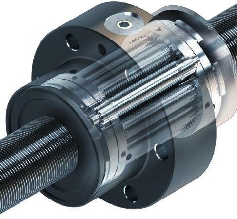
2 2 Screw Assemblies Ball Screw Assemblies BASA Ball Screw Assemblies are the efficient solution for the precise conversion of rotary to linear motion. Building on our many years of experience and extensive engineering expertise, we have developed a product range that fulfills the most diverse requirements. No matter whether you need very high linear speeds, maximum load ratings, or minimum installed length, you will always find the right solution in Rexroth s broad manufacturing spectrum. To make sure your application runs with the utmost accuracy and operational reliability, the individual components in our range have been precisely matched to one another, so complete assemblies can be put together efficiently. More detailed information from page 7 onwards Characteristic features A really varied range, suitable for virtually any requirements Absolutely uniform and stable functioning Especially smooth operation due to optimal ball pick-up and recirculation High load rating due to large number of balls Short nut length Easy installation of the nuts, mounting orientation individually specified Adjustable preloaded single nuts Extensive range comprising various series Matching supplementary individual components such as nut housings and end bearings, also as pillow block units, partly prepared for the installation of suitable motor flanges Planetary Screw Assemblies PLSA The Planetary Screw Assembly PLSA is a complete cylindrical screw assembly with planets as the rolling elements. It serves to convert rotary motion into linear motion and vice versa. The basic functioning of a Planetary Screw Assembly is easy to describe, but the range of designs and the requirements for practical applications are many and varied. Planetary Screw Assemblies are designed to transmit high forces and thus round off the upper end of the screw assembly product portfolio. Planetary Screw Assemblies are screw assemblies in which threaded rollers (the planets) are housed in a threaded nut, their ends being lodged in discs with holes arranged around a pitch circle so that they rotate axially parallel to the special threaded screw, causing the nut to move linearly along the screw. More detailed information from page 193 onwards Characteristic features Smooth functioning due to the principle of synchronized planets Very quiet operation Long service life Compact design High power density Pre-tensioned units available High positioning accuracy and repeatability Low lubricant consumption Bosch Rexroth AG, R ( )


, Bosch")
3 3 Ball Screw Assemblies BASA Screw Assemblies R ( ), Bosch Rexroth AG
4 4 Screw Assemblies Notes General Notes Non-horizontal installation There is no self-locking effect due to the low level of friction between the screw and the nut. The components of the product are designed to last for the product's service life; a major defect may nonetheless arise in exceptional cases, and if the moving part (i.e. the screw assembly nut) is not installed horizontally it may fall off. An additional protection against falling loads is therefore required for non-horizontal installation. Intended use Rexroth Screw Assemblies are components that are used to convert a rotary motion into a linear motion, and vice versa. Rexroth Screw Assemblies are intended exclusively for use in machines for moving and positioning. The product is intended exclusively for professional use and not for private use. Use for the intended purpose also includes the requirement that users must have read and understood the related documentation completely, in particular the Safety Instructions. Misuse Use of the product in any other way than as described under Intended Use is considered to be misuse and is therefore not permitted. If unsuitable products are installed or used in safety-relevant applications, this may lead to uncontrolled operating statuses in the application which can cause personal injury and/or damage to property. The product may only be used in safety-relevant applications if this use has been expressly specified and permitted in the product documentation. Bosch Rexroth AG will not accept any liability for injury or damage caused by misuse of the product. The risks associated with any misuse of the product shall be borne by the user alone. Misuse of the product includes: transporting people General safety instructions The safety rules and regulations of the country in which the product is used must be complied with. All current and applicable accident prevention and environmental regulations must be adhered to. The product may only be used when it is in technically perfect condition. The technical data and environmental conditions stated in the product documentation must be complied with. The product must not be put into service until it has been verified that the final product (for example a machine or system) into which the product has been installed complies with the country-specific requirements, safety regulations and standards for the application. Rexroth Screw Assemblies may not be used in zones with potentially explosive atmospheres as defined in the ATEX directive 94/9/EC. Rexroth Screw Assemblies must never be altered or modified. The user may only perform the work described in the "Quick User Guide" or the "Mounting Instructions for Screw Assemblies." The product must never be disassembled. At high travel speeds a certain amount of noise is caused by the product. If necessary, appropriate measures should be taken to protect hearing. Special safety requirements for specific sectors (e.g. cranes, theaters, foodstuffs) as provided for in laws, directives and standards must be complied with. The following standards must be complied with: ISO 3408 and DIN Bosch Rexroth AG, R ( )
5 Screw Assemblies 5 Directives and standards Rexroth Screw Assemblies are suitable for dynamic linear applications that are moved and positioned reliably and precisely. The machine tool industry and other sectors must observe a series of standards and directives. These requirements can vary significantly worldwide. It is therefore essential to understand the legislation and standards that apply in each particular region. DIN EN ISO This standard is entitled Safety of machinery General principles for design Risk assessment and risk reduction. It gives a general overview and contains a guide to the major developments governing machines and their intended use. Directive 2006/42/EC This European Machinery Directive describes the basic health and safety requirements for the design and manufacture of machinery. The manufacturer of a machine or his authorized representative has a duty to ensure that a risk assessment has been performed in order to determine the health and safety requirements which have to be fulfilled for that machine. The machine must be designed and built with the results of the risk assessment in mind. Ball Screw Assemblies BASA Directive 2001/95/EC This directive covers general safety requirements for any product placed on the market and intended for consumers, or likely to be used by consumers under reasonably foreseeable conditions, including products that are made available to consumers in the context of service provision for use by them. Directive 1999/34/EC This directive concerns liability for defective products and applies to industrially manufactured movables, irrespective of whether they have been incorporated into another movable or into an immovable or not. REGULATION (EC) No. 1907/2006 (REACH) This regulation relates to restrictions on the marketing and use of certain dangerous substances and preparations. Substances means chemical elements and their compounds as they occur in the natural state or as produced by industry. Preparations are mixtures, compounds or solutions consisting of two or more substances. R ( ), Bosch Rexroth AG
6 6 Screw Assemblies Bosch Rexroth AG, R ( )
7 Ball Screw Assemblies BASA Screw Assemblies 7 Ball Screw Assemblies BASA Ball Screw Assemblies BASA R ( ), Bosch Rexroth AG


 Driven nut (FAR-B-S): incorporated from the drive units")


 Nut (FEM-E-D) Nut (FEM-E-D) Pillow block units (SED-F-Z) Pillow")
8 8 Screw Assemblies Ball Screw Assemblies BASA New features at a glance New features at a glance Section entirely on nuts for miniature, speed, standard and high-performance series Tips on: Proper use, misuse, general safety instructions, directives and standards New screw ends Acceptance conditions: Adaptation to DIN or ISO 3408 Screw-in nut ZEV-E-S: higher load ratings, preload possible High-performance series FED-E-B: new sizes: 16x16 / 20x20 / 25x25 / 32x20 / 32x32 Increase in dynamic load capacities by about 20%. approximately 80% longer service life. This made it necessary to adapt the preload classes! Driven nut (FAR-B-S) Driven nut (FAR-B-S): incorporated from the drive units catalog New ordering code BASA 20 x 5R x 3 FEM-E-S T7 R 82Z120 41Z Screws in tolerance grade T3: Lead deviation 0.012/300 mm New, improved tolerance grade for the most demanding requirements. Sole supplier of tolerance grade T3 precision screws Asian series incorporated: Nuts (FEM-E-D, FDM-E-D) Pillow block units (SED-F-Z, SED-L-S, SEE-F-Z) Nut (FEM-E-D) Nut (FEM-E-D) Pillow block units (SED-F-Z) Pillow block units (SED-L-S) Pillow block units (SEE-F-Z) Bosch Rexroth AG, R ( )
9 Ball Screw Assemblies BASA Screw Assemblies Table of contents 9 Table of contents: Ball Screw Assemblies New features at a glance 8 Table of contents 9 Product overview 10 Nuts and Nut Housings 10 Screws 12 Bearing 14 Accessories 15 Definition of Ball Screw Assembly 16 Ball Screw Assemblies for all applications 18 Sample applications 19 Inquiries and orders 20 Nuts, miniature series 24 Overview of formats 24 Single nut with flange FEM-E-B 25 Single nut with flange FEM-E-S 26 Adjustable-preload single nut SEM-E-S 27 Cylindrical Single Nut ZEM-E-S/ZEM-E-K 28 Screw-in nut ZEV-E-S 29 Nuts, Speed Series 30 Single nut with flange with recirculation caps FEP-E-S 31 Nuts, standard series 32 Overview of formats 33 Single nut with flange with recirculation caps FSZ-E-S 34 Single nut with flange with recirculation caps FSZ-E-B 36 Single nut with flange FEM-E-S 38 Single nut with flange FEM-E-C 40 Single nut with flange FEM-E-D 42 Adjustable-preload single nut SEM-E-S 44 Adjustable-preload single nut SEM-E-C 46 Cylindrical Single Nut ZEM-E-S / ZEM-E-K / ZEM-E-A 48 Screw-in nut ZEV-E-S 50 Double nut with flange FDM-E-S 52 Double nut with flange FDM-E-C 54 Double nut with flange FDM-E-D 56 Nuts, high-performance series 58 Nuts, high-performance series 58 Single nut with flange FED-E-B 60 Driven single nut with flange FAR-B-S 62 Screws 64 Screw ends 66 Abbreviations 67 Accessories 98 Overview 98 Nut housing MGS 100 Nut housing MGD 102 Nut housing MGA 104 Pillow Block Unit SEC-F assembly, aluminum 106 Pillow Block Unit SEC-L assembly, aluminum 108 Pillow Block Unit SES-F assembly, steel 110 Pillow Block Unit SES-L assembly, steel 112 Pillow Block Unit SEB-F assembly 114 Pillow Block Unit SEB-L assembly 116 Pillow Block Unit SED-F-Z assembly 118 Pillow Block Unit SED-L-S assembly 120 Flange bearing assembly SEE-F-Z 122 Bearing assembly LAF 124 Bearing assembly LAN 126 Bearing assembly LAD 128 Bearing assembly LAL 130 Slotted Nuts NMA, NMZ and NMG for fixed bearings 132 Assembly tool for slotted nut 133 Ring nut GWR 133 Ball Screw Assembly with front lube unit 134 Measuring pads 139 Arrestor nut 139 Technical data 140 Technical notes 140 Acceptance Conditions and Tolerance Grades 142 Preload and rigidity 146 Frictional torques of the seals 152 Installation 154 Lubrication 157 Grease lubrication 158 Grease lubrication 160 Oil lubrication 166 Lubricants 170 Calculation and examples 172 Calculation 172 Critical speed n cr 176 Permissible axial load on screw F c (buckling load) 177 Design of drive unit FAR-B-S 178 End Bearings 186 Design notes, installation 186 Mounting the housing 187 Lubrication of the end bearings 188 Calculation 189 Ball Screw Assemblies BASA R ( ), Bosch Rexroth AG
10 10 Screw Assemblies Ball Screw Assemblies BASA Product overview Nuts and Nut Housings Nuts Series Miniature Miniature series FEM-E-B / FEM-E-S / SEM-E-S / ZEM-E-S / ZEM-E-K / ZEV-E-S Speed series Single nut with flange with recirculation caps FEP-E-S Size FEM-E-B FEM-E-S SEM-E-S ZEM-E-S d 0 x P x D w ZEM-E-K 6 x 1 x x 2 x x 1 x x 2 x x 2.5 x x 2 x x 5 x 2 12 x 10 x 2 ZEV-E-S Page from Standard series Single nut with flange with recirculation caps FSZ-E-S Single nut with flange with recirculation caps FSZ-E-B Single nut with flange FEM-E-S Single nut with flange DIN , Part 5 FEM-E-C Single nut with flange JIS B 1192 FEM-E-D Adjustable-preload single nut SEM-E-S Adjustable-preload single nut DIN 69051, Part 5 SEM-E-C Cylindrical single nut ZEM-E-S/ZEM-E-K/ZEM- E-A Screw-in nut ZEV-E-S Double nut with flange FDM-E-S Double nut with flange DIN , Part 5 FDM-E-C Series Standard Size d 0 x P x D w FEP-E-S Speed FSZ-E-S FSZ-E-B FEM-E-S FEM-E-C FEM-E-D SEM-E-S SEM-E-C ZEM-E-S ZEM-E-K ZEM-E-A ZEV-E-S FDM-E-S FDM-E-C FEM-E-D 16 x 5 x 3 L L L L 16 x 10 x 3 16 x 16 x 3 20 x 5 x 3 L L L L L 20 x 10 x 3 20 x 20 x x 40 x x 5 x 3 L L L L 25 x 10 x 3 25 x 25 x x 5 x 3.5 L L L L 32 x 10 x x 20 x x 32 x x 64 x x 5 x 3.5 L L L L 40 x 10 x 6 L L L L 40 x 12 x 6 40 x 16 x 6 40 x 20 x 6 40 x 40 x 6 50 x 5 x x 10 x 6 50 x 12 x 6 50 x 16 x 6 50 x 20 x x 25 x x 40 x x 10 x 6 63 x 20 x x 40 x x 10 x x 20 x 12.7 High-performance FED-E-B FAR-B-S Double nut with flange JIS B 1192 FEM-E-D L Standard range, right-hand lead Left-hand lead readily available 56 Bosch Rexroth AG, R ( )
11 Ball Screw Assemblies BASA Screw Assemblies Product overview 11 High-performance series Page Single nut with flange DIN 69051, Part 5 FED-E-B 60 Driven single nut with flange FAR-B-S Nut housing MGS for standard series FEP-E-S FSZ-E-S FEM-E-S SEM-E-S FDM-E-S MGD for standard series FSZ-E-B FEM-E-C SEM-E-C FDM-E-C FED-E-B MGA for cylindrical single nut ZEM-E-S ZEM-E-K ZEM-E-A Diameter d0 Lead P A B A B A B 20 A B C A B C A B C A 25 A B A B A B 32 A B C A B C A B C A B C A 40 A B C A B C B B A B C A B C 50 A B A B B A B A B A B 63 A B B B 80 A B B A = MGS B = MGD C = MGA 62 Page Ball Screw Assemblies BASA R ( ), Bosch Rexroth AG
12 12 Screw Assemblies Ball Screw Assemblies BASA Product overview Screws Precision screw BAS Tolerance grades: T5, T7, T9 Sizes 6 to 12 6x1Rx0.8 6x2Rx0.8 8x1Rx0.8 8x2Rx1.2 8x2.5Rx x2Rx1.2 12x5Rx2 12x10Rx Screw length Page 65 Tolerance grades: T5, T7, T9 Left-hand lead Size 16x5Lx3 20x5Lx3 25x5Lx3 32x5Lx3.5 40x5Lx3.5 40x10Lx Screw length Screws in tolerance grade T3 (longer versions and larger sizes available on request) 16x5Rx3 16x10Rx3 20x5Rx3 25x5Rx3 25x10Rx3 32x5Rx3.5 32x10Rx x20Rx x5Rx3.5 40x10Rx6 40x20Rx Screw length Standard, available at short notice on request Bosch Rexroth AG, R ( )
13 Ball Screw Assemblies BASA Screw Assemblies Product overview 13 Precision screw BAS Tolerance grades: T5, T7, T9 Sizes 16 to 80 Page 65 16x5Rx3 16x10Rx3 16x16Rx3 20x5Rx3 20x10Rx3 20x20Rx3.5 20x40Rx3.5 25x5Rx3 25x10Rx3 25x25Rx3.5 32x5Rx3.5 32x10Rx x20Rx x32Rx x64Rx x5Rx3.5 40x10Rx6 40x12Rx6 40x16Rx6 40x20Rx6 40x40Rx6 50x5Rx3.5 50x10Rx6 50x12Rx6 50x16Rx6 50x20Rx6.5 50x25Rx6.5 50x40Rx6.5 63x10Rx6 63x20Rx6.5 63x40Rx6.5 80x10Rx6.5 80x20Rx Screw length Ball Screw Assemblies BASA Standard, available at short notice On request Maximum length (assembled) on request Screw ends Page 66 R ( ), Bosch Rexroth AG
14 14 Screw Assemblies Ball Screw Assemblies BASA Product overview Bearing Pillow block unit SEC-F Page 106 SEC-L 108 SES-F Lead P A A SES-L 8 A A A 112 Diameter d0 12 A A A 16 A A A 20 A B C D E A B C D E A B C D E A B C SEB-F 25 A C D E A C D E A C A B C D E A B C D E A B C D E A B C A B C 40 A B C E A B C E A B C A B C A B C E A B C E 50 A E A E A A A E A A E SEB-L 63 A A A A A SED-F-Z A = SEB-F and SEB-L B = SEC-F and SEC-L C = SES-F and SES-L D = SED-F and SED-L E = SEE-F 118 SED-L-S 120 SEE-F-Z 122 Bosch Rexroth AG, R ( )


15 Ball Screw Assemblies BASA Screw Assemblies Product overview 15 Bearing Bearing Page LAF Lead P , LAN LAD LAL Diameter d0 Diameter d0 LAF Lead P LAL LAN / LAD 2, Ball Screw Assemblies BASA Accessories Single parts Slotted nut NMA, NMZ Page 132 Assembly tool for NMA/NMZ/NMG Ring nut GWR Front lube unit 134 Measuring pads 139 Arrestor nut 139 Acceptance conditions Page 142 R ( ), Bosch Rexroth AG
16 16 Screw Assemblies Ball Screw Assemblies BASA Product overview Definition of Ball Screw Assembly ISO defines a Ball Screw Assembly as follows: A unit consisting of a ball screw shaft, ball nut and balls which is able to convert rotary motion into linear motion, and vice versa. The basic functioning of a Ball Screw Assembly is easy to describe, but there are numerous different designs and requirements for practical applications. Several innovations and adaptations have contributed to the extension of the product portfolio. Rexroth Ball Screw Assemblies provide design engineers with diverse solutions for transport and positioning tasks with driven screws or with driven nuts. At Rexroth you will be sure to find exactly the kind of tailor-made products you need for special applications. The flange nuts from the standard series are available in versions with Rexroth, DIN, or JIS mounting dimensions. In order to make it easier in future for customers to decide between particular series and/or sizes in terms of delivery time too, we have introduced A, B and C categories for nuts. Each individual nut part number is assigned to a particular category. A parts (GoTo Europe Focused Delivery Program) are always stocked to meet average order quantities. B parts (corresponds to standard range) are in stock, whereas For C parts, inquiries have to be made regarding the delivery capability. For deliveries within Europe, there is the quantity-dependent GoTo Europe Focused Delivery Program. The special delivery times and quantities can be found in the GoTo Europe Focused Delivery Program catalog. Almost all single nuts in the version with backlash can be easily mounted on the screw by the customer himself, especially during servicing. In addition, the standard series adjustable-preload single nut allows the customer to carry out preload adjustment in-house. Appropriate nut housings for the standard series and several types of end bearings are also stocked. Precision screws in a variety of sizes and of unequaled quality have long been an essential part of our product range. Our comprehensive, worldwide stocks guarantee fast response times in every location. Availability is one advantage, low prices another. Every nut featured in this catalog can be combined with precision screws. Precision screws can also be supplied without nuts to allow customers to machine the screw ends themselves. For special servicing jobs, please consult us. Calculation software and product configuration tool The Linear Motion Designer (LMD) calculation software is used for designing and calculating Ball Screw Assemblies BASA. The CAD model is created via the product configuration tool. This can be accessed via the Rexroth online portal / econfigurators and Tools. This online configuration tool makes it possible to visually configure Ball Screw Assemblies quickly to match specific requirements in each case. The tool automatically checks the plausibility of changed parameters. The link to the eshop means that Ball Screw Assemblies can be directly ordered at any time of the day or night. Bosch Rexroth AG, R ( )


17 Ball Screw Assemblies BASA Screw Assemblies Product overview 17 Ball Screw Assemblies BASA Benefits Smooth functioning due to the principle of internal recirculation Especially smooth running due to the optimal pick-up of balls from the raceway Adjustable-pre-tensioned single nut High load rating due to large number of balls Short nut length No protruding parts, nut is easily mounted Smooth outer shell Effective, wiping sealing Large range of series available ex stock R ( ), Bosch Rexroth AG


18 18 Screw Assemblies Ball Screw Assemblies BASA Product overview Ball Screw Assemblies for all applications Drive units You will find further system solutions in our catalog on Rexroth Drive Units. This catalog contains Ball Screw Assemblies with a protecting housing, including versions with integrated screw supports and matching AC servo motors. To perform particularly demanding positioning tasks we have developed the Integrated Measuring System for Ball Rail and Roller Rail Systems. This enables us to achieve maximum design flexibility and operating precision. Bosch Rexroth AG, R ( )


19 Ball Screw Assemblies BASA Screw Assemblies Sample applications 19 Sample applications Rexroth Ball Screw Assemblies have been successfully implemented worldwide in the following areas: Cutting operations Forming operations Automation and handling Woodworking Electrical and electronics Printing and paper industry Machining center Vertical axis with driven nut Injection molding machines Food and packaging industries Medical technology Textile industry etc. Press brake Ball Screw Assemblies BASA Lathe R ( ), Bosch Rexroth AG


20 20 Screw Assemblies Ball Screw Assemblies BASA Inquiries and orders Inquiries and orders All nuts, screws and end machining details can now be defined with the ordering code as a complete precision Ball Screw Assembly. We have taken account of all the existing selection criteria as well as adding new ones. The diversity of possible combinations and specifications is basically limitless. Attention is focused in particular on the definition of end machining details. For many design versions there is a prepared definition, which means that a suitable solution can be devised for virtually any application. If you wish to send us an inquiry, simply complete the form at the end of this catalog. If you submit a manufacturing drawing as a CAD file in Pro/E, STEP or DXF, you can the data to us. If the drawing exists on paper only, we will of course accept a scan or a drawing sent by conventional mail. If no drawing is available, please specify your wishes using the variable ordering code. The available options are shown at several places in the catalog. Each customer-specific Ball Screw Assembly is issued with an ID number when an order is placed. For queries or repeat orders, simply quote this number. If you know the specific ordering code you can also easily generate a CAD drawing yourself in numerous file formats via the functionality provided on our website. Rexroth offers an online product configuration tool for this and for directly submitting product requests. To configure specific solutions quickly and easily, simply go to This online tool enables you to visually configure the specific Ball Screw Assembly or Planetary Screw Assembly that you need. You can select any catalog option or any defined product modification. The tool automatically checks the plausibility of changed parameters. Once configuration is complete, 2D and 3D data is available for download in all established formats. As regards end machining, you can choose either standard versions or tailor-made solutions. Rexroth machines the screw ends of the Ball Screw Assembly or Planetary Screw Assembly so that it matches the customer's connecting design and fulfills the desired requirements. The configuration tool which is incorporated into the eshop allows you to obtain a price for customer-specific Ball Screw Assemblies, and also to directly order the product. The screw diameter size that can be selected for Ball Screw Assemblies ranges from 6 to 80 millimeters. In addition, any type of nut can be chosen. Customers who are registered in the eshop can generate manufacturing drawings as well as requesting CAD models. This drawing can then be used directly by our production departments, which accelerates order processing and delivery. What's more, in this case you can order directly in the eshop. In the case of configuration without prior registration, only CAD models are provided. We can refer to this if an order is placed, and use it to produce a manufacturing drawing. Bosch Rexroth AG, R ( )
21 Ball Screw Assemblies BASA Screw Assemblies Inquiries and orders 21 The ordering code provided on page 22 covers all the parameters of a Ball Screw Assembly. Once you have defined the nominal diameter and lead and entered the total length, the functionality guides you through a succession of dialog boxes allowing you to select the desired options. Nominal diameters, leads Lead P Available ball nut sizes Combinable with VSE Nominal diameter d , Ball Screw Assemblies BASA Overall length L tot of a Ball Screw Assembly Overall length L tot R ( ), Bosch Rexroth AG
22 22 Screw Assemblies Ball Screw Assemblies BASA Inquiries and orders Identification system for short product names BASA / ordering data Ball Screw Assembly BASA 20 x 5 R x3 FEM-E-C T7 R 81 A Z A Z Ball Screw Assembly Size Nominal diameter (mm) Lead (mm) Direction of lead R right, L left Ball diameter (mm) Nut type FEM-E-B Single nut with flange miniature series Nut rework FEP-E-S FSZ-E-S FSZ-E-B FEM-E-S Single nut with flange with recirculation caps Single nut with flange with recirculation caps Single nut with flange with recirculation caps Single nut with flange FEM-E-C Single nut with flange DIN 69051, Part 5 FEM-E-D Single nut with flange JIS B 1192 SEM-E-S Adjustable-preload single nut SEM-E-C Adjustable-preload single nut DIN 69051, Part 5 ZEM-E-S ZEM-E-K ZEM-E-A ZEV-E-S FDM-E-S Cylindrical single nut Cylindrical single nut Cylindrical single nut Screw-in nut Double nut with flange FDM-E-C Double nut with flange DIN 69051, Part 5 FEM-E-D Double nut with flange JIS B 1192 FED-E-B FAR-B-S Single nut with flange Driven single nut with flange Number of ball track turns in the nut 00 no rework 01 additional surface (B flange) 4) Sealing system 0 no seals 2 1) reinforced seal 1 standard seal 3 2) low-friction seal Preload classes 0... C0 (standard backlash) 4... C4 (high preload DN 6) ) Accuracy Screw 1... C00 (reduced backlash) 5... C5 (average preload DN 6) ) 2... C3 3) (high preload SN 5) ) 6... C2 (average preload SN) 3... C1 (slight preload SN 5) ) T3, T5, T7, T9 R... Precision screw BAS Left screw end Form: standard form Right screw end Overall length [mm] Option (machining of end face): Versions: A with wrench flat on the ball screw B with wrench flat on the collar Z centering per DIN 332-D S hex socket G female thread K none standard version... see left screw end Documentation 0 Standard (acceptance test report) 2 Torque test report Lubrication 1 Lead test report 3 Lead and torque test report 0 Preserved 1 Preserved and nut with basic greasing 3 Front Lube Unit on right, ball nut with basic greasing 2 Front Lube Unit on left, ball nut with basic greasing 4 Front Lube Unit at both ends, ball nut with basic greasing 1) only for d 0 25 to 63; consider the higher frictional torque! See page 152 5) SN = Single nut 2) See page 152 for sizes 6) DN = Double nut 3) only for d 0 16 to 80 4) for FEM-E-C and FDM-E-C with mounting dimensions according to DIN 69051, Part 5 flange type B. FDM-E-C only available as a complete Ball Screw Assembly. Bosch Rexroth AG, R ( )
23 Ball Screw Assemblies BASA Screw Assemblies Inquiries and orders 23 Mounting direction of nut types Definition: The centering diameter on a nut with flange, the slotted nut on a driven nut, and the lube bore on a cylindrical nut points to the right end of the screw. Note: The front lube unit is delivered ready-mounted to the Ball Screw Assembly. FEM FDM SEM FSZ Centering diameter D 1 Centering diameter D 1 FED FEP Ball Screw Assemblies BASA ZEV Lube port ZEM Lube port FAR Slotted nut R ( ), Bosch Rexroth AG


 3 C1 Moderate preload (single nut) 4 C4 High preload (double nut) 5 C5 Average preload")
24 24 Screw Assemblies Ball Screw Assemblies BASA Nuts, miniature series Nuts, miniature series Miniature series Miniature series Ball Screw Assemblies are available with nominal diameters of 6 12 mm, and leads of 1 10 mm. The nut types are flange, cylindrical and adjustable-preload single nuts as well as screw-in nuts. Overview of formats FEM-E-B FEM-E-S SEM-E-S ZEM-E-S Preload classes Option Preload class Definition ZEV-E-S 0 C0 Standard backlash 1 C00 Reduced backlash 2 C3 High preload (single nut) 3 C1 Moderate preload (single nut) 4 C4 High preload (double nut) 5 C5 Average preload (double nut) 6 C2 Average preload (single nut) See nut versions for allocation of the preload classes Bosch Rexroth AG, R ( )

25 Ball Screw Assemblies BASA Screw Assemblies Nuts, miniature series 25 Single nut with flange FEM-E-B Rexroth connection dimensions flange type B With seals, preload class: C0, C00 Except for size 8 x 2.5 and 12 x 5/10: Preload class C1. Tolerance grade: T5, T7, T9 d 0 = nominal diameter P = lead (R = right-hand side) D W = ball diameter i = number of ball track turns Ordering data: BASA 8 x 2R x 1.2 FEM-E-B T7 R 831K062 41K Category Size Part number Load ratings 3) Linear speed 1) d 0 x P x D w - i dyn. C (N) stat. C 0 (N) v max (m/min) C 6 x 1R x ) R ,080 1,030 6 C 6 x 2R x ) R ,070 1, C 8 x 1R x ) R ,310 1,850 6 C 8 x 2R x ) R ,360 2, C 8 x 2.5R x R ,640 2, B 12 x 2R x ) R ,690 4, B 12 x 5R x 2-3 R ,560 5, B 12 x 10R x 2-2 R ,000 3, ) See Characteristic speed d 0 n on page 141 and Critical speed n cr on page 176 2) Supplied only as complete Ball Screw Assembly. 3) The load ratings are valid for tolerance grade T5 only. For other tolerance grades, please take into account the correction factor f ac on page 141. ø D 4 L 7 D 7 D w 30 D 6 D 1 30 L14 d2 d1 d0 Ball Screw Assemblies BASA Lube port L3 L 4 L D 5 Size (mm) Mass d 1 d 2 D 1 D 4 D 5 D 6 D 7 L L 3 L 4 L 7 L 14 m d 0 x P x D w - i g6 (kg) 6 x 1R x ,020 6 x 2R x ,020 8 x 1R x ,035 8 x 2R x ,050 8 x 2.5R x , x 2R x , x 5R x , x 10R x ,085 R ( ), Bosch Rexroth AG
26 26 Screw Assemblies Ball Screw Assemblies BASA Nuts, miniature series Single nut with flange FEM-E-S Rexroth connection dimensions With seals Preload class: C0, C00, C1 Tolerance grade: T5, T7, T9 d 0 = nominal diameter P = lead (R = right-hand) D W = ball diameter i = number of ball track turns Ordering data: BASA 12 x 5R x 2 FEM-E-S T7 R 81K060 41K Category Size Part number Load ratings 2) Linear speed 1) d 0 x P x D w - i dyn. C (N) stat. C 0 (N) v max (m/min) C 8 x 2.5R x R ,640 2, B 12 x 5R x 2-3 R ,560 5, B 12 x 10R x 2-2 R ,000 3, ) See Characteristic speed d 0 n on page 141 and Critical speed n cr on page 176 2) The load ratings are valid for tolerance grade T5 only. For other tolerance grades, please take into account the correction factor f ac on page 141. Lube port 2) at flange center L 10 D 7 D5 D1 D1 0,05 0,1 ϕ D 6 S ϕ D w L 3 L 4 L 6x60 d2 d1 d0 L Size (mm) Mass d 1 d 2 D 1 D 5 D 6 D 7 L L 3 L 4 L 10 S 3) ϕ m d 0 x P x D w - i g6 ( ) (kg) 8 x 2.5R x Ø x 5R x M x 10R x M ) Lube port machining: flat surface L 3 15 mm, for size 8 x 2.5 a DIN 3405 funnel-type lube nipple is provided. Bosch Rexroth AG, R ( )
 D W = ball diameter i = number of ball track turns Ordering data: BASA 12 x 5R x 2 SEM-E-S - 3 00 1 2 T7 R 81K060 41K060 250 0 1 Ball Screw Assemblies BASA")

27 Ball Screw Assemblies BASA Screw Assemblies Nuts, miniature series 27 Adjustable-preload single nut SEM-E-S Rexroth connection dimensions With seals Adjustable preload Tolerance grade: T5, T7 d 0 = nominal diameter P = lead (R = right-hand) D W = ball diameter i = number of ball track turns Ordering data: BASA 12 x 5R x 2 SEM-E-S T7 R 81K060 41K Ball Screw Assemblies BASA Category Size Part number Load ratings 2) Linear speed 1) Centering diameter D 1 dyn. C stat. C 0 v max after adjustment d 0 x P x D w - i (N) (N) (m/min) min. (mm) max. (mm) C 8 x 2.5R x R ,640 2, ,987 B 12 x 5R x 2-3 R ,560 5, ,940 23,975 B 12 x 10R x 2-2 R ,000 3, ,940 23,975 1) See Characteristic speed d 0 n on page 141 and Critical speed n cr on page 176 2) The load ratings are valid for tolerance grade T5 only. For other tolerance grades, please take into account the correction factor f ac on page 141. Lube port 2) at flange center L 5 L 10 4x60 S ϕ D5 D1 +0,7 D1 0,05 D 1 0,1 D 6 D 7 L 3 L L 4 ø6 3,4 D 7 4x60 D w S D5 9 D1 D 6 d2 d1 d0 Version for 8 x 2.5 R x L 3 L 4 Size (mm) Mass d 1 d 2 D 1 D 5 D 6 D 7 L L 3 L 4 L 5 L 10 S 3) ϕ m d 0 x P x D w - i f9 ( ) (kg) 8 x 2.5R x Ø x 5R x M x 10R x M ) Lube port machining: flat surface L 3 15 mm, for size 8 x 2.5 a DIN 3405 funnel-type lube nipple is provided. R ( ), Bosch Rexroth AG
 D W = ball diameter i = number of ball track turns Ordering data: BASA 12 x 5R x 2 ZEM-E-S - 3")
28 28 Screw Assemblies Ball Screw Assemblies BASA Nuts, miniature series Cylindrical Single Nut ZEM-E-S/ZEM-E-K 1) Rexroth connection dimensions With seals Preload class: C0, C00, C1 Except for size 12 x 2: Preload class C0, C00 Tolerance grade: T5, T7, T9 d 0 = nominal diameter P = lead (R = right-hand) D W = ball diameter i = number of ball track turns Ordering data: BASA 12 x 5R x 2 ZEM-E-S T7 R 81K060 41K Category Size Part number Load ratings 3) Linear speed 2) d 0 x P x D w - i dyn. C stat. C 0 v max (N) (N) (m/min) C 8 x 2.5R x R ,640 2, B 12 x 2R x 1,2-4 1) R ,690 4, B 12 x 5R x 2-3 R ,560 5, B 12 x 5R x 2-3 1) R ,560 5, B 12 x 10R x 2-2 R ,000 3, B 12 x 10R x 2-2 1) R ,000 3, ) ZEM-E-K / nuts for Rexroth modules and drive units 2) See Characteristic speed d 0 n on page 141 and critical speed n cr on page 176 3) The load ratings are valid for tolerance grade T5 only. For other tolerance grades, please take into account the correction factor f ac on page 141. L 11 L 6 A A T 1 D 1 B D 4 0,2 D w d2 d1 d0 L L 7 Lube port D w Size (mm) Mass d 0 x P x D w - i d 1 d 2 D 1 D 4 L L 6 L 7 L 11 B T 1 m g6 ± P (kg) 8 x 2.5R x x 2R x ) x 5R x x 5R x 2-3 1) x 10R x x 10R x 2-2 1) Bosch Rexroth AG, R ( )
29 Ball Screw Assemblies BASA Screw Assemblies Nuts, miniature series 29 Screw-in nut ZEV-E-S Rexroth connection dimensions With low-friction seal, preload class: C0, C00, C1 Tolerance grade: T5, T7, T9 d 0 = nominal diameter P = lead (R = right-hand) D W = ball diameter i = number of ball track turns Ordering data: BASA 12 x 5R x 2 ZEV-E-S T7 R 81K060 41K Category Size Part number Load ratings 2) Linear speed 1) d 0 x P x D w - i dyn. C (N) stat. C 0 (N) v max (m/min) B 12 x 5R x 2-3 R ,560 5, B 12 x 10R x 2-2 R ,000 3, ) See Characteristic speed d 0 n on page 141 and Critical speed n cr on page 176 2) The load ratings are valid for tolerance grade T5 only. For other tolerance grades, please take into account the correction factor f ac on page 141. D 4 L 7 D 8 D w d2 d1 d 0 G1 D 1 Ball Screw Assemblies BASA Lube port Hole for assembly wrench L 15 L Size (mm) Mass d 1 d 2 D 1 D 4 D 8 G 1 L L 7 L 15 m d 0 x P x D w - i h10 ±0.3 (kg) 12 x 5R x M20 x x 10R x M20 x R ( ), Bosch Rexroth AG
30 30 Screw Assemblies Ball Screw Assemblies BASA Nuts, Speed Series Nuts, Speed Series Speed series Speed series Ball Screw Assemblies are available with nominal diameters of mm, and leads of mm. The nut type is a single nut with flange. The distinguishing feature of the speed series is its compact design. Multi-start screws allow a higher load rating with a short nut. The oversquare leads enable the realization of high traversing speeds. Preload classes Option Preload class Definition 0 C0 Standard backlash 1 C00 Reduced backlash 2 C3 High preload (single nut) 3 C1 Moderate preload (single nut) 4 C4 High preload (double nut) 5 C5 Average preload (double nut) 6 C2 Average preload (single nut) See nut versions for allocation of the preload classes Bosch Rexroth AG, R ( )
31 Ball Screw Assemblies BASA Screw Assemblies Nuts, Speed Series 31 Single nut with flange with recirculation caps FEP-E-S Rexroth connection dimensions With seals, preload class: C0, C00, C1 Tolerance grade: T5, T7, T9 c Do not exert force on the plastic recirculation caps or allow them to collide with end stops. Note: Supplied only as complete Ball Screw Assembly. d 0 = nominal diameter P = lead (R = right-hand) D W = ball diameter i = number of ball track turns Ordering data: BASA 25 x 25R x 3.5 FEM-E-S T5 R 81K170 41K Category Size Part number Load ratings 2) Linear speed 1) d 0 x P x D w - i dyn. C (N) stat. C 0 (N) v max (m/min) C 20 x 40R x R ,000 26, C 25 x 25R x R ,700 39, C 32 x 32R x R ,300 57, C 32 x 64R x R ,100 49, ) See Characteristic speed d 0 n on page 141 and Critical speed n cr on page 176 2) The load ratings are valid for tolerance grade T5 only. For other tolerance grades, please take into account the correction factor f ac on page 141. L K L 8 6,6 M6 D 6 30 D K D1 D K D5 6x60 L 3 L L 4 L K D w d2 d1 d 0 Ball Screw Assemblies BASA Lube port Plastic recirculation cap Plastic recirculation cap Size (mm) Mass d 1 d 2 D 1 D 5 D 6 D K L L 3 L 4 L 8 L K m d 0 x P x D w - i g6 ±0.5 (kg) 20 x 40R x x 25R x x 32R x x 64R x R ( ), Bosch Rexroth AG

32 32 Screw Assemblies Ball Screw Assemblies BASA Nuts, standard series Nuts, standard series Standard series Ball Screw Assemblies are available with nominal diameters of mm, and leads of 5 40 mm. The nut types are flange, cylindrical and adjustable-preload single nuts, double nuts with flange, as well as screw-in nuts. Benefits High axial load-bearing capacity High dynamics High rigidity Low friction Available from stock in many versions and sizes Nut housing with reference edge (both sides) Preload classes Option Preload class Definition 0 C0 Standard backlash 1 C00 Reduced backlash 2 C3 High preload (single nut) 3 C1 Moderate preload (single nut) 4 C4 High preload (double nut) 5 C5 Average preload (double nut) 6 C2 Average preload (single nut) See nut versions for allocation of the preload classes Bosch Rexroth AG, R ( )

33 Ball Screw Assemblies BASA Screw Assemblies Nuts, standard series 33 Overview of formats FSZ-E-S FSZ-E-B FEM-E-S Ball screw assemblies BASA FEM-E-C FEM-E-D SEM-E-S SEM-E-C ZEM-E-S ZEV-E-S FDM-E-S FDM-E-C FEM-E-D R ( ), Bosch Rexroth AG
34 34 Screw Assemblies Ball Screw Assemblies BASA Nuts, standard series Single nut with flange with recirculation caps FSZ-E-S Rexroth connection dimensions With seals, preload class: C0, C00, C1, C2, C3 Tolerance grade: T3 2), T5, T7, T9 c Do not exert force on the plastic recirculation caps or allow them to collide with end stops. cc When setting up applications, do not allow components to collide with the front lube unit. Ordering data: BASA 20 x 5R x 3 FSZ-E-S T7 R 81K120 41K d 0 = nominal diameter P = lead (R = right-hand) D W = ball diameter i = number of ball track turns Category Size Part number Load ratings 3) Linear speed 1) d 0 x P x D w - i dyn. C (N) stat. C 0 (N) v max (m/min) B 20 x 5R x 3-4 R ,200 21, B 25 x 5R x 3-4 R ,100 27, B 25 x 10R x 3-4 R ,800 27, B 32 x 5R x R ,900 40, B 32 x 10R x R ,000 58, B 32 x 20R x R ,200 21, B 40 x 5R x R ,900 64, B 40 x 10R x 6-4 R ,000 86, B 40 x 20R x 6-3 R ,500 62, ) See Characteristic speed d 0 n on page 141 and Critical speed n cr on page 176 2) Tolerance grade T3 for sizes shown in table page 12 3) The load ratings are valid for tolerance grade T3 and T5 only. For other tolerance grades, please take into account the correction factor f ac on page 141. Bosch Rexroth AG, R ( )
35 Ball Screw Assemblies BASA Screw Assemblies Nuts, standard series 35 Plastic recirculation cap Lube port at flange center D 7 S D K L K D 1 +0,7 L 5 L 3 L 4 L D1 L 10 L K D K D 1 0,1 0,05 D 5 D 6 Plastic recirculation cap D w 6x60 D w 30 d2 d1 d 0 Ball Screw Assemblies BASA Size (mm) Mass d 1 d 2 D 1 D 5 D 6 D 7 D K L L 3 L 4 L 5 L 10 L K S m d 0 x P x D w - i g6 ±0.5 (kg) 20 x 5R x M x 5R x M x 10R x M x 5R x M x 10R x M x 20R x M x 5R x M8x x 10R x M8x x 20R x M8x R ( ), Bosch Rexroth AG
36 36 Screw Assemblies Ball Screw Assemblies BASA Nuts, standard series Single nut with flange with recirculation caps FSZ-E-B Mounting dimensions similar to DIN 69051, Part 5 flange type B With seals, Preload class: C0, C00, C1, C2, C3 Tolerance grade: T3 2), T5, T7, T9 c Do not exert force on the plastic recirculation caps or allow them to collide with end stops. cc When setting up applications, do not allow components to collide with the front lube unit. Ordering data: BASA 20 x 5R x 3 FSZ-E-B T7 R 81K120 41K d 0 = nominal diameter P = lead (R = right-hand) D W = ball diameter i = number of ball track turns Category Size Part number Load ratings 3) Linear speed 1) d 0 x P x D w - i dyn. C (N) stat. C 0 (N) v max (m/min) B 20 x 5R x 3-4 R ,200 21, B 25 x 5R x 3-4 R ,100 27, B 25 x 10R x 3-4 R ,800 27, B 32 x 5R x R ,900 40, B 32 x 10R x R ,000 58, B 32 x 20R x R ,200 21, B 40 x 5R x R ,900 64, B 40 x 10R x 6-4 R ,000 86, B 40 x 20R x 6-3 R ,500 62, ) See Characteristic speed d 0 n on page 141 and Critical speed n cr on page 176 2) Tolerance grade T3 for sizes shown in table page 12 3) The load ratings are valid for tolerance grade T3 and T5 only. For other tolerance grades, please take into account the correction factor f ac on page 141. Bosch Rexroth AG, R ( )
37 S Ball Screw Assemblies BASA Screw Assemblies Nuts, standard series 37 Plastic recirculation cap Lube port at flange center D 7 D K L K D 1 +0,7 L 5 L 3 L 4 L D1 L 10 D w L K d2 D K d1 D 1 0,1 0,05 d 0 D 5 Plastic recirculation cap D 7 D 5 S D 6 22,5 30 L 9 L9 BB2 BB1 Ball Screw Assemblies BASA D 6 D 5 Size (mm) Mass d 1 d 2 D 1 D 5 Hole D 6 D 7 D K L L 3 L 4 L 5 L 9 L 10 L K S m d 0 x P x D w - i g6 pattern ±0.5 (kg) 20 x 5R x BB M x 5R x BB M x 10R x BB M x 5R x BB M x 10R x BB M x 20R x BB M x 5R x BB M8x x 10R x BB M8x x 20R x BB M8x R ( ), Bosch Rexroth AG
38 38 Screw Assemblies Ball Screw Assemblies BASA Nuts, standard series Single nut with flange FEM-E-S Rexroth connection dimensions With seals Left-hand version in some cases Preload class: C0, C00, C1, C2, C3 Tolerance grade: T3 2), T5, T7, T9 Note: The front lube unit is only available for the right-hand version. cc When setting up applications, do not allow components to collide with the front lube unit. d 0 = nominal diameter P = lead (R = right-hand, L = left-hand) D W = ball diameter i = number of ball track turns Bosch Rexroth AG, R ( ) Ordering data: BASA 20 x 5R x 3 FEM-E-S T7 R 82Z120 41Z Category Size Part number Load ratings 3) Linear speed 1) d 0 x P x D w - i dyn. C (N) stat. C 0 (N) v max (m/min) A 16 x 5R x 3-4 R ,800 16, A 16 x 10R x 3-3 R ,500 12, A 16 x 16R x 3-2 R ,560 7, A 20 x 5R x 3-4 R ,200 21, A 20 x 10R x 3-4 R ,900 21, A 20 x 20R x R ,900 12, A 25 x 5R x 3-4 R ,100 27, A 25 x 10R x 3-4 R ,800 27, A 25 x 25R x R ,100 15, A 32 x 5R x R ,900 40, A 32 x 10R x R ,000 58, A 32 x 20R x R ,200 21, A 32 x 32R x R ,100 22, A 40 x 5R x R ,900 64, A 40 x 10R x 6-4 R ,000 86, A 40 x 10R x 6-6 R , , A 40 x 20R x 6-3 R ,500 62, A 40 x 40R x 6-2 R ,600 40, B 50 x 5R x R ,400 81, B 50 x 10R x 6-6 R , , C 50 x 16R x 6-6 R , , B 50 x 20R x R ,500 87, B 50 x 40R x R ,500 55, B 63 x 10R x 6-6 R , , B 63 x 20R x R , , B 63 x 40R x R ,300 74, C 80 x 10R x R , , C 80 x 20R x R , , Versions with left-hand lead B 16 x 5L x 3-4 R ,800 16, B 20 x 5L x 3-4 R ,200 21, B 25 x 5L x 3-4 R ,100 27, B 32 x 5L x R ,900 40, B 40 x 5L x R ,900 64, B 40 x 10L x 6-4 R ,000 86, ) See Characteristic speed d 0 n on page 141 and Critical speed n cr on page 176 2) Tolerance grade T3 for sizes shown in table page 12 3) The load ratings are valid for tolerance grade T3 and T5 only. For other tolerance grades, please take into account the correction factor f ac on page 141.
39 Ball Screw Assemblies BASA Screw Assemblies Nuts, standard series 39 Lube port 4) at flange center L 10 BB3 BB4 BB5 D 7 D 7 D 7 S S D5 D 1 +0,7 L 3 L 5 D1 L 4 L L 3 L 0,05 0,1 D1 D1 L 4 BF1 BF2 D 6 Lube port 4) at flange center 4x90 ϕ D w D 6 d2 d1 d0 6x60 ϕ D 6 S 8x45 ϕ Ball Screw Assemblies BASA 4) Lube port machining: flat surface L 3 15 mm, countersink L 3 > 15 mm; Size (mm) Mass d 1 d 2 D 1 D 5 Hole pattern D 6 D 7 Design L L 3 L 4 L 5 L 10 S 4) ϕ m d 0 x P x D w - i g6 style ( ) (kg) 16 x 5R x BB BF M x 10R x BB BF M x 16R x BB BF M x 5R x BB BF M x 10R x BB BF M x 20R x BB BF M x 5R x BB BF M x 10R x BB BF M x 25R x BB BF M x 5R x BB BF M x 10R x BB BF M x 20R x BB BF M x 32R x BB BF M x 5R x BB BF M8x x 10R x BB BF M8x x 10R x BB BF _ 75 M8x x 20R x BB BF M8x x 40R x BB BF M8x x 5R x BB BF M8x x 10R x BB BF M8x x 16R x BB BF M8x x 20R x BB BF M8x x 40R x BB BF M8x x 10R x BB BF M8x x 20R x BB BF M8x x 40R x BB BF M8x x 10R x BB BF M8x x 20R x BB BF M8x Versions with left-hand lead 16 x 5L x BB BF M x 5L x BB BF M x 5L x BB BF M x 5L x BB BF M x 5L x BB BF M8x x 10L x BB BF M8x R ( ), Bosch Rexroth AG
40 40 Screw Assemblies Ball Screw Assemblies BASA Nuts, standard series Single nut with flange FEM-E-C Mounting dimensions similar to DIN 69051, Part 5 Flange type C (flange type B available. See ordering code p. 22) With seals With left-hand version in some cases Preload class: C0, C00, C1, C2, C3 Tolerance grade: T3 2), T5, T7, T9 Note: The front lube unit is only available for the right-hand version. cc When setting up applications, do not allow components to collide with the front lube unit. d 0 = nominal diameter P = lead (R = right-hand, L = left-hand) D W = ball diameter i = number of ball track turns Ordering data: BASA 20 x 5R x 3 FEM-E-C T7 R 82Z120 41Z Category Size Part number Load ratings 3) Linear speed 1) dyn. C (N) stat. C 0 (N) v max (m/min) d 0 x P x D w - i A 16 x 5R x 3-4 R ,800 16, A 16 x 10R x 3-3 R ,500 12, A 16 x 16R x 3-3 R ,200 12, A 20 x 5R x 3-4 R ,200 21, A 20 x 10R x 3-4 R ,900 21, A 20 x 20R x R ,000 18, A 25 x 5R x 3-4 R ,100 27, A 25 x 10R x 3-4 R ,800 27, A 25 x 25R x R ,600 23, A 32 x 5R x R ,900 40, A 32 x 10R x R ,000 58, A 32 x 20R x R ,600 33, A 32 x 32R x R ,400 34, A 40 x 5R x R ,900 64, A 40 x 10R x 6-4 R ,000 86, A 40 x 10R x 6-6 R , , C 40 x 12R x 6-4 R ,900 86, C 40 x 16R x 6-4 R ,600 85, A 40 x 20R x 6-3 R ,500 62, A 40 x 40R x 6-3 R ,400 62, B 50 x 5R x R ,400 81, B 50 x 10R x 6-6 R , , C 50 x 12R x 6-6 R , , C 50 x 16R x 6-6 R , , B 50 x 20R x R , , B 50 x 40R x R ,800 85, B 63 x 10R x 6-6 R , , B 63 x 20R x R , , B 63 x 40R x R , , C 80 x 10R x R , , C 80 x 20R x R , , Versions with left-hand lead B 16 x 5L x 3-4 R ,800 16, B 20 x 5L x 3-4 R ,200 21, B 25 x 5L x 3-4 R ,100 27, B 32 x 5L x R ,900 40, B 40 x 5L x R ,900 64, B 40 x 10L x 6-4 R ,000 86, ) See Characteristic speed d 0 n on page 141 and Critical speed n cr on page 176 2) Tolerance grade T3 for sizes shown in table page 12 3) The load ratings are valid for tolerance grade T3 and T5 only. For other tolerance grades, please take into account the correction factor f ac on page 141. Bosch Rexroth AG, R ( )
41 0 Ball Screw Assemblies BASA Screw Assemblies Nuts, standard series 41 Lube port at flange center 4) L 10 BB2 d 0 32 BB1 d 0 40 D 7 D 7 S 6) S 6) D 5 D1 L 3 L 4 D w L 0,05 D 1 0,1 d 0 d1 d2 9 0 D 6 22,5 L D 6 30 L 9 Ball Screw Assemblies BASA 4) Lube port machining: flat surface L 3 15 mm, countersink L 3 > 15 mm; Size (mm) Mass d 1 d 2 D 1 D 5 Hole pattern D 6 D 7 L L 3 L 4 L 5) 9 L 10 S 4) m d 0 x P x D w - i g6 (kg) 16 x 5R x BB M x 10R x BB M x 16R x BB M x 5R x BB M x 10R x BB M x 20R x BB M x 5R x BB M x 10R x BB M x 25R x BB M x 5R x BB M x 10R x BB M x 20R x BB M x 32R x BB M x 5R x BB M8x x 10R x BB M8x x 10R x BB M8x x 12R x BB M8x x 16R x BB M8x x 20R x BB M8x x 40R x BB M8x x 5R x BB M8x x 10R x BB M8x x 12R x BB M8x x 16R x BB M8x x 20R x BB M8x x 40R x BB M8x x 10R x BB M8x x 20R x BB M8x x 40R x BB M8x x 10R x BB M8x x 20R x BB M8x Versions with left-hand lead 16 x 5L x BB M x 5L x BB M x 5L x BB M x 5L x BB M x 5L x BB M8x x 10L x BB M8x ) Flange type B (two flat surfaces) option available! 6) With left-hand lead the lube port position mirrors its position with right-hand lead! R ( ), Bosch Rexroth AG
42 42 Screw Assemblies Ball Screw Assemblies BASA Nuts, standard series Single nut with flange FEM-E-D Mounting dimensions as per JIS B1192, Table 5 With seals, preload class: C0, C00, C1, C2, C3 Tolerance grades T3 2), T5, T7, T9. cc When setting up applications, do not allow components to collide with the front lube unit. Ordering data: BASA 20 x 5R x 3 FEM-E-D T7 R 8ABZ150 41Z d 0 = nominal diameter P = lead (R = right-hand) D W = ball diameter i = number of ball track turns Category Size Part number Load ratings 3) Linear speed 1) dyn. C stat. C 0 v max d 0 x P x D w - i (N) (N) (m/min) C 20 x 5R x 3-4 R A0 17,200 21, C 20 x 10R x 3-4 R A0 16,900 21, C 20 x 20R x R A0 10,900 12, C 25 x 5R x 3-4 R A0 19,100 27, C 25 x 10R x 3-4 R A0 18,800 27, C 32 x 5R x R A0 25,900 40, C 32 x 10R x R A0 38,000 58, C 32 x 20R x R A0 16,200 21, C 40 x 5R x R A0 34,900 64, C 40 x 10R x 6-4 R A0 60,000 86, C 40 x 20R x 6-3 R A0 45,500 62, C 40 x 40R x 6-2 R A0 30,600 40, C 50 x 5R x R A0 38,400 81, C 50 x 10R x 6-6 R A0 95, , C 50 x 20R x R A0 57,500 87, C 50 x 40R x R A0 38,500 55, C 63 x 10R x 6-6 R A0 106, , C 63 x 20R x R A0 63, , C 63 x 40R x R A0 44,300 74, C 80 x 10R x R A0 130, , C 80 x 20R x R A0 315, , ) See Characteristic speed d 0 n on page 141 and Critical speed n cr on page 176 2) Tolerance grade T3 for sizes shown in table page 12 3) The load ratings are valid for tolerance grade T3 and T5 only. For other tolerance grades, please take into account the correction factor f ac on page 141. Bosch Rexroth AG, R ( )
43 D 6 Ball Screw Assemblies BASA Screw Assemblies Nuts, standard series 43 M6 4) L 10 S 4) L D 5 L 3 D 1 L 4 L 0,05 D 1 0,1 6x60 D 12 D w D 7 d 2 d 1 d 0 Ball Screw Assemblies BASA 4) Use lube nipple with tapered thread Size (mm) Mass d 1 d 2 D 1 D 5 D 6 D 7 D 12 L L 3 L 4 L 10 L 12 S 4) m d 0 x P x D w - i g6 (kg) 20 x 5R x M x 10R x M x 20R x M x 5R x M x 10R x M x 5R x M x 10R x M x 20R x M x 5R x Rc 1/ x 10R x Rc 1/ x 20R x Rc 1/ x 40R x Rc 1/ x 5R x Rc 1/ x 10R x Rc 1/ x 20R x Rc 1/ x 40R x Rc 1/ x 10R x Rc 1/ x 20R x Rc 1/ x 40R x Rc 1/ x 10R x Rc 1/ x 20R x Rc 1/ R ( ), Bosch Rexroth AG
44 44 Screw Assemblies Ball Screw Assemblies BASA Nuts, standard series Adjustable-preload single nut SEM-E-S Rexroth connection dimensions With seals Left-hand version in some cases Preload adjustable Tolerance grade T3 2, T5, T7 Note: The front lube unit is only available for the right-hand version. cc When setting up applications, do not allow components to collide with the front lube unit. d 0 = nominal diameter P = lead (R = right-hand, L = left-hand) D W = ball diameter i = number of ball track turns Ordering data: BASA 20 x 5R x 3 SEM-E-S T7 R 82Z120 41Z Category Size Part number Load ratings 3) Linear speed 1) Centering diameter D 1 after dyn. C stat. C 0 v max adjustment d 0 x P x D w - i (N) (N) (m/min) min. (mm) max. (mm) B 16 x 5R x 3-4 R ,800 16, ,940 27,975 B 16 x 10R x 3-3 R ,500 12, ,940 27,975 B 16 x 16R x 3-2 R ,560 7, ,945 32,973 B 20 x 5R x 3-4 R ,200 21, ,935 32,970 B 20 x 20R x R ,900 12, ,945 37,973 B 25 x 5R x 3-4 R ,100 27, ,935 37,970 B 25 x 10R x 3-4 R ,800 27, ,935 37,970 B 25 x 25R x R ,100 15, ,945 47,973 B 32 x 5R x R ,900 40, ,935 47,970 B 32 x 10R x R ,000 58, ,970 B 32 x 20R x R ,200 21, ,941 55,969 B 32 x 32R x R ,100 22, ,941 55,969 B 40 x 5R x R ,900 64, ,931 55,966 B 40 x 10R x 6-4 R ,000 86, ,931 62,966 B 40 x 20R x 6-3 R ,500 62, ,941 62,969 B 40 x 40R x 6-2 R ,600 40, ,941 71,969 B 50 x 5R x R ,400 81, ,931 67,966 B 50 x 10R x 6-6 R , , ,931 71,966 B 50 x 20R x R ,500 87, ,936 84,964 B 50 x 40R x R ,500 55, ,936 84,964 B 63 x 10R x 6-6 R , , ,926 84,961 B 63 x 20R x R , , ,936 94,964 B 63 x 40R x R ,300 74, ,936 94,964 C 80 x 10R x R , , , ,961 C 80 x 20R x R , , , ,959 Versions with left-hand lead B 16 x 5L x 3-4 R ,800 16, ,975 B 20 x 5L x 3-4 R ,200 21, ,935 32,970 B 25 x 5L x 3-4 R ,100 27, ,970 B 32 x 5L x R ,900 40, ,935 47,970 B 40 x 5L x R ,900 64, ,931 55,966 B 40 x 10L x 6-4 R ,000 86, ,931 62,966 1) See Characteristic speed d 0 n on page 141 and Critical speed n cr on page 176 2) Tolerance grade T3 for sizes shown in table page 12 3) The load ratings are valid for tolerance grade T3 and T5 only. For other tolerance grades, please take into account the correction factor f ac on page 141. Bosch Rexroth AG, R ( )
45 Ball Screw Assemblies BASA Screw Assemblies Nuts, standard series 45 Lube port 4) at flange center right L 5 L 10 4x60 S ϕ left S 60 ϕ D5 D1 +0,7 L 3 L D1 L 4 0,05 D 1 0,1 D 6 D 7 BB7 BB7 D w D 6 D 7 d2 d1 d0 Ball Screw Assemblies BASA 4) Lube port machining: flat surface L 3 15 mm, countersink L 3 > 15 mm. For size 8 x 2.5, a funnel-type lube nipple DIN 3405 is provided. Size (mm) Mass d 1 d 2 D 1 D 5 Hole pattern D 6 D 7 L L 3 L 4 L 5 L 10 S 4) ϕ m d 0 x P x D w - i f9 ( ) (kg) 16 x 5R x BB M x 10R x BB M x 16R x BB M x 5R x BB M x 20R x BB M x 5R x BB M x 10R x BB M x 25R x BB M x 5R x BB M x 10R x BB M x 20R x BB M x 32R x BB M x 5R x BB M8x x 10R x BB M8x x 20R x BB M8x x 40R x BB M8x x 5R x BB M8x x 10R x BB M8x x 20R x BB M8x x 40R x BB M8x x 10R x BB M8x x 20R x BB M8x x 40R x BB M8x x 10R x BB M8x x 20R x BB M8x Versions with left-hand lead 16 x 5L x BB M x 5L x BB M x 5L x BB M x 5L x BB M x 5L x BB M8x x 10L x BB M8x R ( ), Bosch Rexroth AG
46 46 Screw Assemblies Ball Screw Assemblies BASA Nuts, standard series Adjustable-preload single nut SEM-E-C Mounting dimensions similar to DIN 69051, Part 5 flange type C With seals Adjustable preload Tolerance grade T3 2, T5, T7 cc When setting up applications, do not allow components to collide with the front lube unit. d 0 = nominal diameter P = lead (R = right-hand) D W = ball diameter i = number of ball track turns Ordering data: BASA 20 x 5R x 3 SEM-E-C T7 R 82Z120 41Z Category Size Part number Load ratings 3) Linear speed 1) Centering diameter D 1 dyn. C stat. C 0 v max after adjustment d 0 x P x D w - i (N) (N) (m/min) min. (mm) max. (mm) B 16 x 5R x 3-4 R ,800 16, ,940 27,975 B 16 x 10R x 3-3 R ,500 12, ,940 27,975 B 16 x 16R x 3-3 R ,200 12, ,950 27,978 B 20 x 5R x 3-4 R ,200 21, ,935 35,970 B 20 x 20R x R ,000 18, ,945 35,973 B 25 x 5R x 3-4 R ,100 27, ,935 39,970 B 25 x 10R x 3-4 R ,800 27, ,935 39,970 B 25 x 25R x R ,600 23, ,945 39,973 B 32 x 5R x R ,900 40, ,935 49,970 B 32 x 10R x R ,000 58, ,935 49,970 B 32 x 20R x R ,600 33, ,945 49,973 B 32 x 32R x R ,400 34, ,945 49,973 B 40 x 5R x R ,900 64, ,931 62,966 B 40 x 10R x 6-4 R ,000 86, ,931 62,966 C 40 x 12R x 6-4 R ,900 86, ,931 62,966 B 40 x 20R x 6-3 R ,500 62, ,941 62,969 B 40 x 40R x 6-3 R ,400 62, ,941 62,969 B 50 x 5R x R ,400 81, ,931 74,966 B 50 x 10R x 6-6 R , , ,931 74,966 C 50 x 12R x 6-6 R , , ,931 74,966 B 50 x 20R x R , , ,941 74,969 B 50 x 40R x R ,800 85, ,941 74,969 B 63 x 10R x 6-6 R , , ,926 89,961 B 63 x 20R x R , , ,936 94,964 B 63 x 40R x R , , ,936 94,964 C 80 x 10R x R , , , ,961 C 80 x 20R x R , , , ,959 1) See Characteristic speed d 0 n on page 141 and Critical speed n cr on page 176 2) Tolerance grade T3 for sizes shown in table page 12 3) The load ratings are valid for tolerance grade T3 and T5 only. For other tolerance grades, please take into account the correction factor f ac on page 141. Bosch Rexroth AG, R ( )
47 Ball Screw Assemblies BASA Screw Assemblies Nuts, standard series 47 Lube port 4) BB2 d 0 32 BB1 d 0 40 L 8 D 7 L 5 L 10 S D7 S D 5 D 1 +0,7 L 3 L 4 L D w d2 D 1 d1 d0 0,05 D 1 0,1 90 D 6 22,5 L D 6 30 L 9 Ball Screw Assemblies BASA 4) Lube port machining: flat surface L 3 15 mm, countersink L 3 > 15 mm Size (mm) Mass d 1 d 2 D 1 D 5 Hole pattern D 6 D 7 L L 3 L 4 L 5 L 8 L 9 L 10 S 4) m d 0 x P x D w - i f9 (kg) 16 x 5R x BB M x 10R x BB M x 16R x BB M x 5R x BB M x 20R x BB M x 5R x BB M x 10R x BB M x 25R x BB M x 5R x BB M x 10R x BB M x 20R x BB M x 32R x BB M x 5R x BB M8x x 10R x BB M8x x 12R x BB M8x x 20R x BB M8x x 40R x BB M8x x 5R x BB M8x x 10R x BB M8x x 12R x BB M8x x 20R x BB M8x x 40R x BB M8x x 10R x BB M8x x 20R x BB M8x x 40R x BB M8x x 10R x BB M8x x 20R x BB M8x R ( ), Bosch Rexroth AG
, T5, T7, T9 1) 2) d 0 = nominal diameter P = lead (R = right-hand, L = left-hand) D W = ball diameter i = number of ball track turns 1)")
48 48 Screw Assemblies Ball Screw Assemblies BASA Nuts, standard series Cylindrical Single Nut ZEM-E-S / ZEM-E-K / ZEM-E-A Rexroth connection dimensions With seals Left-hand version in some cases Preload class: C0, C00, C1, C2, C3 Tolerance grade T3 4), T5, T7, T9 1) 2) d 0 = nominal diameter P = lead (R = right-hand, L = left-hand) D W = ball diameter i = number of ball track turns 1) ZEM-E-K / nuts for Rexroth modules and drive units 2) ZEM-E-A / nuts with mounting dimensions as per DIN 69051, Part 5 3) See Characteristic speed d 0 n on page 141 and Critical speed n cr on page 176 4) Tolerance grade T3 for sizes shown in table page 12 5) The load ratings are valid for tolerance grade T3 and T5 only. For other tolerance grades, please take into account the correction factor f ac on page 141. Ordering data: BASA 20 x 5R x 3 ZEM-E-S T7 R 82Z120 41Z Category Size Part number Load ratings 5) Linear speed 3) d 0 x P x D w - i dyn. C stat. C 0 v max (N) (N) (m/min) B 16 x 5R x 3-4 R ,800 16, B 16 x 5R x 3-4 R ) 14,800 16, B 16 x 10R x 3-3 R ,500 12, B 16 x 10R x 3-3 R ) 11,500 12, B 16 x 10R x 3-3 R ) 11,500 12, B 16 x 16R x 3-2 R ,560 7, B 16 x 16R x 3-2 R ) 7,560 7, B 16 x 16R x 3-3 R ,200 12, B 16 x 16R x 3-3 R ) 11,200 12, B 20 x 5R x 3-4 R ) 17,200 21, B 20 x 5R x 3-5 R ,000 27, B 20 x 10R x 3-4 R ,900 21, B 20 x 20R x R ,900 12, B 20 x 20R x R ,000 18, B 20 x 20R x R ) 16,000 18, B 25 x 5R x 3-4 R ,100 27, B 25 x 10R x 3-4 R ,800 27, B 25 x 25R x R ,100 15, B 25 x 25R x R ,600 23, B 32 x 5R x R ,900 40, B 32 x 5R x R ) 25,900 40, B 32 x 10R x R ,000 58, B 32 x 10R x R ) 38,000 58, B 32 x 20R x R ,200 21, B 32 x 20R x R ,600 33, B 32 x 32R x R ,100 22, B 32 x 32R x R ,400 34, B 40 x 5R x R ,900 64, B 40 x 5R x R ) 34,900 64, B 40 x 10R x 6-4 R ,000 86, B 40 x 10R x 6-6 R , , B 40 x 20R x 6-3 R ,500 62, B 40 x 40R x 6-2 R ,600 40, B 40 x 40R x 6-3 R ,400 62, B 50 x 5R x R ,400 81, B 50 x 10R x 6-6 R , , B 50 x 20R x R ,500 87, B 63 x 10R x 6-6 R , , C 80 x 10R x R , , Versions with left-hand lead B 16 x 5L x 3-4 R ,800 16, B 20 x 5L x 3-5 R ,000 27, B 20 x 5L x 3-4 R ) 17,200 21, B 25 x 5L x 3-4 R ,100 27, B 32 x 5L x R ,900 40, B 40 x 5L x R ,900 64, B 40 x 10L x 6-4 R ,000 86, Bosch Rexroth AG, R ( )
49 Ball Screw Assemblies BASA Screw Assemblies Nuts, standard series 49 L 11 L 6 A T 1 D 1 B A D 4 0,2 L L 7 Lube port D w d2 d1 d 0 Ball Screw Assemblies BASA Size (mm) Mass d 0 x P x D w - i d 1 d 2 D 1 D 4 L L 6 L 7 L 11 B T 1 m g6 ± P (kg) 16 x 5R x x 5R x x 10R x x 10R x x 10R x x 16R x x 16R x x 16R x x 16R x x 5R x x 5R x x 10R x x 20R x x 20R x x 20R x x 5R x x 10R x x 25R x x 25R x x 5R x x 5R x x 10R x x 10R x x 20R x x 20R x x 32R x x 32R x x 5R x x 5R x x 10R x x 10R x x 20R x x 40R x x 40R x x 5R x x 10R x x 20R x x 10R x x 10R x Versions with left-hand lead 16 x 5L x x 5L x x 5L x x 5L x x 5L x x 5L x x 10L x R ( ), Bosch Rexroth AG
50 50 Screw Assemblies Ball Screw Assemblies BASA Nuts, standard series Screw-in nut ZEV-E-S Rexroth connection dimensions With low-friction seal, preload class: C0, C00, C1 Tolerance grade T3 2), T5, T7, T9 Ordering data: BASA 20 x 5R x 3 ZEV-E-S T7 R 81K120 41K d 0 = nominal diameter P = lead (R = right-hand) D W = ball diameter i = number of ball track turns Category Size Part number Load ratings 3) Linear speed 1) d 0 x P x D w - i dyn. C (N) stat. C 0 (N) v max (m/min) B 16 x 5R x 3-3 R ,300 11, B 16 x 10R x 3-3 R ,500 12, B 20 x 5R x 3-4 R ,200 21, B 25 x 5R x 3-7 R ,400 48, B 25 x 10R x 3-5 R ,200 34, B 32 x 5R x R ,700 50, B 32 x 10R x R ,000 58, ) See Characteristic speed d 0 n on page 141 and Critical speed n cr on page 176 2) Tolerance grade T3 for sizes shown in table page 12 3) The load ratings are valid for tolerance grade T3 and T5 only. For other tolerance grades, please take into account the correction factor f ac on page 141. Bosch Rexroth AG, R ( )
51 Ball Screw Assemblies BASA Screw Assemblies Nuts, standard series 51 Lube port G1 D 4 L 7 D 8 Hole for assembly wrench L 15 L D 1 D w d2 d1 d 0 Ball Screw Assemblies BASA Size (mm) Mass d 1 d 2 D 1 D 4 D 8 G 1 L L 7 L 15 m d 0 x P x D w - i h10 ±0.3 (kg) 16 x 5R x M26 x x 10R x M26 x x 5R x M35 x x 5R x M40 x x 10R x M40 x x 5R x M48 x x 10R x M48 x R ( ), Bosch Rexroth AG
52 52 Screw Assemblies Ball Screw Assemblies BASA Nuts, standard series Double nut with flange FDM-E-S Rexroth connection dimensions With seals, preload class: C4, C5 Tolerance grades T3 2), T5, T7 Note: Supplied only as complete Ball Screw Assembly. cc When setting up applications, do not allow components to collide with the front lube unit. d 0 = nominal diameter Ordering data: P = lead (R = right-hand) BASA 20 x 5R x 3 FDM-E-S T7 R 82Z120 41Z D W = ball diameter i = number of ball track turns Category Size Part number Load ratings 3) Linear speed 1) d 0 x P x D w - i dyn. C (N) stat. C 0 (N) v max (m/min) C 16 x 5R x 3-4 R ,800 16, C 20 x 5R x 3-4 R ,200 21, C 25 x 5R x 3-4 R ,100 27, C 25 x 10R x 3-4 R ,800 27, C 32 x 5R x R ,900 40, C 32 x 10R x R ,000 58, C 40 x 5R x R ,900 64, C 40 x 10R x 6-4 R ,000 86, C 40 x 10R x 6-6 R , , C 40 x 20R x 6-3 R ,500 62, C 50 x 5R x R ,400 81, C 50 x 10R x 6-4 R , , C 50 x 10R x 6-6 R , , C 50 x 20R x R , , C 63 x 10R x 6-4 R , , C 63 x 10R x 6-6 R , , C 63 x 20R x R , , C 80 x 10R x R , , C 80 x 20R x R , , ) See Characteristic speed d 0 n on page 141 and Critical speed n cr on page 176 2) Tolerance grade T3 for sizes shown in table page 12 3) The load ratings are valid for tolerance grade T3 and T5 only. For other tolerance grades, please take into account the correction factor f ac on page 141. Bosch Rexroth AG, R ( )
53 Ball Screw Assemblies BASA Screw Assemblies Nuts, standard series 53 Lube port 4) at flange center BB3 BB4 L 10 D 7 S D 7 S D 5 L 3 D 1 L 4 L 0,04 D 1 0,2 D 6 BB5 D 7 4x90 S 6x ,5 D 6 D w Ball Screw Assemblies BASA D 6 8x45 d 2 d 1 d 0 4) Lube port machining: flat surface L 3 15 mm, countersink L 3 > 15 mm Size (mm) Mass d 1 d 2 D 1 D 5 Hole pattern D 6 D 7 L L 3 L 4 L 10 S 4) m d 0 x P x D w - i g6 (kg) 16 x 5R x BB M x 5R x BB M x 5R x BB M x 10R x BB M x 5R x BB M x 10R x BB M x 5R x BB M8x x 10R x BB M8x x 10R x BB M8x x 20R x BB M8x x 5R x BB M8x x 10R x BB M8x x 10R x BB M8x x 20R x BB M8x x 10R x BB M8x x 10R x BB M8x x 20R x BB M8x x 10R x BB M8x x 20R x BB M8x R ( ), Bosch Rexroth AG
54 54 Screw Assemblies Ball Screw Assemblies BASA Nuts, standard series Double nut with flange FDM-E-C Mounting dimensions similar to DIN 69051, Part 5 Flange type C (flange type B available. See ordering code p. 22) With seals, preload class: C4, C5 Tolerance grades T3 2), T5, T7 Note: Supplied only as complete Ball Screw Assembly. cc When setting up applications, do not allow components to collide with the front lube unit. d 0 = nominal diameter P = lead (R = right-hand) D W = ball diameter i = number of ball track turns Ordering data: BASA 20 x 5R x 3 FDM-E-S T7 R 82Z120 41Z Category Size Part number Load ratings 3) Linear speed 1) d 0 x P x D w - i dyn. C (N) stat. C 0 (N) v max (m/min) C 16 x 5R x 3-4 R ,800 16, C 20 x 5R x 3-4 R ,200 21, C 25 x 5R x 3-4 R ,100 27, C 25 x 10R x 3-4 R ,800 27, C 32 x 5R x R ,900 40, C 32 x 10R x R ,000 58, C 40 x 5R x R ,900 64, C 40 x 10R x 6-4 R ,000 86, C 40 x 10R x 6-6 R , , C 40 x 20R x 6-3 R ,500 62, C 50 x 5R x R ,400 81, C 50 x 10R x 6-4 R , , C 50 x 10R x 6-6 R , , C 50 x 20R x R , , C 63 x 10R x 6-4 R , , C 63 x 10R x 6-6 R , , C 63 x 20R x R , , C 80 x 10R x R , , C 80 x 20R x R , , ) See Characteristic speed d 0 n on page 141 and Critical speed n cr on page 176 2) Tolerance grade T3 for sizes shown in table page 12 3) The load ratings are valid for tolerance grade T3 and T5 only. For other tolerance grades, please take into account the correction factor f ac on page 141. Bosch Rexroth AG, R ( )
55 Ball Screw Assemblies BASA Screw Assemblies Nuts, standard series 55 Lube port 4) at flange center BB2 D 7 d 0 32 L 10 S D 5 L 3 D 1 L 4 L D w 0,04 0,2 D S 30 22,5 L 9 L 9 BB1 D 7 d 0 40 D 6 d 2 d 1 d 0 Ball Screw Assemblies BASA D 6 4) Lube port machining: flat surface L 3 15 mm, countersink L 3 > 15 mm Size (mm) Mass d 1 d 2 D 1 D 5 Hole pattern D 6 D 7 L L 3 L 4 L 5) 9 L 10 S 4) m d 0 x P x D w - i g6 (kg) 16 x 5R x BB M x 5R x BB M x 5R x BB M x 10R x BB M x 5R x BB M x 10R x BB M x 5R x BB M8x x 10R x BB M8x x 10R x BB M8x x 20R x BB M8x x 5R x BB M8x x 10R x BB M8x x 10R x BB M8x x 20R x BB M8x x 10R x BB M8x x 10R x BB M8x x 20R x BB M8x x 10R x BB M8x x 20R x BB M8x ) Flange type B (two flat surfaces) option available! R ( ), Bosch Rexroth AG
56 56 Screw Assemblies Ball Screw Assemblies BASA Nuts, standard series Double nut with flange FDM-E-D Mounting dimensions as per JIS B1192, Table 5 With seals, preload class: C4, C5 Tolerance grades T3 2), T5, T7. Note: Supplied only as complete Ball Screw Assembly. cc When setting up applications, do not allow components to collide with the front lube unit. d 0 = nominal diameter P = lead (R = right-hand) D W = ball diameter i = number of ball track turns Ordering data: BASA 20 x 5R x 3 FDM-E-D T7 R 8ABZ150 41Z Category Size Part number Load ratings 3) Linear speed 1) dyn. C stat. C 0 v max d 0 x P x D w - i (N) (N) (m/min) C 20 x 5R x 3-4 R B0 17,200 21, C 25 x 5R x 3-4 R B0 19,100 27, C 25 x 10R x 3-4 R B0 18,800 27, C 32 x 5R x R B0 25,900 40, C 32 x 10R x R B0 38,000 58, C 40 x 5R x R B0 34,900 64, C 40 x 10R x 6-4 R B0 60,000 86, C 40 x 20R x 6-3 R B0 45,500 62, C 50 x 5R x R B0 38,400 81, C 50 x 10R x 6-4 R B0 66, , C 50 x 20R x R B0 90, , C 63 x 10R x 6-4 R B0 74, , C 63 x 20R x R B0 100, , C 80 x 10R x R B0 130, , C 80 x 20R x R B0 315, , ) See Characteristic speed d 0 n on page 141 and Critical speed n cr on page 176 2) Tolerance grade T3 for sizes shown in table page 12 3) The load ratings are valid for tolerance grade T3 and T5 only. For other tolerance grades, please take into account the correction factor f ac on page 141. Bosch Rexroth AG, R ( )
57 Ball Screw Assemblies BASA Screw Assemblies Nuts, standard series 57 M6 4) L 10 S 4) D w d 2 d 1 d 0 D 5 D 1 L 3 L 4 L 0,04 D 1 0,2 D 6 6X60 30 D 12 L 12 D 7 Ball Screw Assemblies BASA 4) Use lube nipple with tapered thread Size (mm) Mass d 1 d 2 D 1 D 5 D 6 D 7 D 12 L L 3 L 4 L 10 L 12 S 4) m d 0 x P x D w - i g6 (kg) 20 x 5R x M x 5R x M x 10R x M x 5R x M x 10R x M x 5R x Rc 1/ x 10R x Rc 1/ x 20R x Rc 1/ x 5R x Rc 1/ x 10R x Rc 1/ x 20R x Rc 1/ x 10R x Rc 1/ x 20R x Rc 1/ x 10R x Rc 1/ x 20R x Rc 1/ R ( ), Bosch Rexroth AG

58 58 Screw Assemblies Ball Screw Assemblies BASA Nuts, high-performance series Nuts, high-performance series High-performance series HP series Ball Screw Assemblies are available with nominal diameters of mm, and leads of mm. The HP nut type is a single nut with flange which is available with a driven screw or as a driven nut. FED-E-B FAR-B-S Preload classes Option Preload class Definition 0 C0 Standard backlash 1 C00 Reduced backlash 2 C3 High preload (single nut) 3 C1 Moderate preload (single nut) 4 C4 High preload (double nut) 5 C5 Average preload (double nut) 6 C2 Average preload (single nut) See nut versions for allocation of the preload classes Bosch Rexroth AG, R ( )
59 Ball Screw Assemblies BASA Screw Assemblies Nuts, high-performance series 59 Driven single nut with flange FAR-B-S Fundamental advantages of systems with driven nuts Moment of inertia In the case of long screws, the screw does not have to be rotated in the acceleration phase, only the nut. The mass moment of inertia of the screw is not therefore critical. The moment of inertia of the nut is comparatively low and it is no longer dependent on the required stroke. Dynamics The intricate end bearing designs required for high dynamics, for example, fixed bearing on both ends with angular-contact ball bearings, are no longer necessary. Screw extenders Since the screw is stationary, relatively effort is needed to stretch the screw Increase in permissible axial loading (buckling load); not limited by end bearings Compensation of temperature influences Increase in overall rigidity Ball Screw Assemblies BASA Design and manufacturing tolerances The use of nuts with a high level of axial and radial runout precision minimizes the induced screw vibration. All functional components are supplied from a single source. In-house designs are no longer needed. Liquid cooling Improved cooling can easily be provided by using a hollow-bored screw: cooling of the stationary screw can be provided with comparatively little effort. Controlled cooling virtually eliminates changes in length due to temperature fluctuations. User benefits Economic efficiency provided by complete unit Adjustment to various speeds and loads is possible using the screw lead and the speed reducing belt Small installation space thanks to its compact construction Integral functionality and little installation work for the customer Low system costs High positioning accuracy For particularly demanding positioning tasks, it can be combined with the direct position measuring system that is integrated in the guide rail Ball Screw Assemblies (BASA) screw 2 Driven nut FAR R ( ), Bosch Rexroth AG
60 60 Screw Assemblies Ball Screw Assemblies BASA Nuts, high-performance series Single nut with flange FED-E-B Mounting dimensions similar to DIN 69051, Part 5 flange type B Nut for significantly increasing the dynamic and static load capacity With seals of preload class: C0, C00, C1, C2 Tolerance grade T3 3), T5, T7, T9 Note: Supplied only as complete Ball Screw Assembly. cc When setting up applications, do not allow components to collide with the front lube unit. Ordering data: BASA 40x20R x 6 FED-E-B T5 R 82Z300 41K Category Size Part number Load ratings 5) max. static load 1) 2) Linear speed 4) dyn. C stat. C 0 v max d 0 x P x D W - i (N) (N) (N) (m/min) B 16 x 16 R x 3-6 R ,800 24,200 24, B 20 x 20 R x R ,700 38,100 38, B 25 x 25 R x R ,500 47,100 47, B 32 x 20 R x R ,300 67,300 67, B 32 x 32 R x R ,900 68,000 68, B 40 x 20 R x 6-8 R , ,100 87, B 40 x 40 R x 6-6 R , ,500 83, B 50 x 20 R x R , , , B 50 x 25 R x R , , , B 50 x 40 R x R , , , B 63 x 20 R x R , , , B 63 x 40 R x R , , , ) The load-bearing capability of the rolling contact is greater than the mechanical strength of the nut body, therefore the maximum static load data has been included. 2) When selecting end bearings, please contact your local distribution partner for assistance. 3) Tolerance grade T3 for sizes shown in table page 12 4) See Characteristic speed d 0 n on page 141 and Critical speed n cr on page 176 5) The load ratings are valid for tolerance grade T3 and T5 only. For other tolerance grades, please take into account the correction factor f ac on page 141. d 0 = nominal diameter P = lead (R = right-hand) D W = ball diameter i = number of ball track turns Bosch Rexroth AG, R ( )
61 Ball Screw Assemblies BASA Screw Assemblies Nuts, high-performance series 61 BB2 d 0 32 BB1 d 0 40 Lube port 6 ) at flange center L 10 D 7 D 7 30 S 90 D 6 D 5 22,5 S D1 L 5 L 3 L 4 L 0,05 0,1 D w D1 L D 6 D 5 L14 Ball Screw Assemblies BASA d2 d1 d0 6) Lube port machining: flat surface L 3 15 mm, countersink L 3 > 15 mm Size (mm) Mass d 1 d 2 D 1 D 5 Hole pattern D 6 D 7 L L 3 L 4 L 5 L 10 L 14 S 6) m d 0 x P x D W - i g6 (kg) 16 x 16 R x BB M x 20 R x BB M x 25 R x BB M x 20 R x BB M x 32 R x BB M x 20 R x BB M8x x 40 R x BB M8x x 20 R x BB M8x x 25 R x BB M8x x 40 R x BB M8x x 20 R x BB M8x x 40 R x BB M8x R ( ), Bosch Rexroth AG
62 62 Screw Assemblies Ball Screw Assemblies BASA Nuts, high-performance series Driven single nut with flange FAR-B-S Rexroth connection dimensions With seals, preload class: C1, C2, C3 Tolerance grade T3 2), T5, T7 The unit consists of: nut, angular-contact thrust ball bearing and slotted nut NMZ When in standstill, it can be relubricated with NLGI Class 2 grease via the stationary lube port of the bearing outer race Note: Supplied only as complete Ball Screw Assembly. d 0 = nominal diameter P = lead (R = right-hand) D W = ball diameter i = number of ball track turns Ordering data: BASA 40x20R x 6 FAR-B-S T5 R 51K300 51K Category FAR Size Part number Load ratings 1) 4) Mass Mass moment Frictional torque Max. speed 3) size Module of inertia Bearing dyn. C stat. C 0 m FAR J rotfar M RL n G d 0 x P x D w - i (N) (N) (kg) (kg m ) (Nm) (rpm) C x 10R x R ,000 58, x 20R x R ,600 33, x 32R x R ,400 34, C x 10R x 6-5 R , , x 20R x 6-3 R ,500 62, x 40R x 6-3 R ,400 62, C x 10R x 6-6 R , , x 20R x R , , x 40R x R ,800 85, C x 10R x 6-6 R , , x 20R x R , , x 40R x R , , ) Load ratings calculated according to DIN ISO ) Tolerance grade T3 for sizes shown in table page 12 3) Limited by the max. speed of the bearing. Bearing pre-tensioned without external operating load. Duty cycle 25%; max. steady-state temp. +50 C 4) The load ratings are valid for tolerance grade T3 and T5 only. For other tolerance grades, please take into account the correction factor f ac on page 141. FAR rigidity levels FAR Size Rigidity Overall rigidity of the nut unit (N/µm) size Screw Bearing Preload class C1 Preload class C2 Preload class C3 R S R al R G R G R G d 0 x P x D w - i (Nm/µm) (N/µm) x 10R x x 20R x x 32R x x 10R x x 20R x x 40R x x 10R x , x 20R x , x 40R x , x 10R x , x 20R x , x 40R x , Bosch Rexroth AG, R ( )
63 Ball Screw Assemblies BASA Screw Assemblies Nuts, high-performance series 63 BASA nut Bearing S L lube port Slotted nut NMZ 6x60 d L D5 D 7 Belt pulley L 3 B L L FAR B N DN DL K L D 6 8 x 45 S L Lube port D w d2 d1 d 0 Ball Screw Assemblies BASA FAR size Size Dimensions (mm) d 1 d 2 L FAR D 5 D 6 D 7 L 3 D L B L K L d L S 5) L D N B N d 0 x P x D w - i h / x 10R x M M x 20R x x 32R x x 10R x M M x 20R x x 40R x x 10R x M M x 20R x x 40R x x 10R x M M x 20R x x 40R x ) Condition on delivery: lube ports S L sealed by setscrews (M6). The desired lube port can be opened by removing the set screw. R ( ), Bosch Rexroth AG
64 64 Screw Assemblies Ball Screw Assemblies BASA Screws Precision screw D w d 2 d 1 d 0 L tot Please state length in the Inquiry/Order Form L tot = overall length Bosch Rexroth AG, R ( )
65 Ball Screw Assemblies BASA Screw Assemblies Screws 65 Size Part number (mm) Moment of inertia Maximum length (mm) Mass Tolerance grade Js Standard on request d 0 x P x D W T5 T7 T9 d 1 d 2 (kg cm 2 /m) (kg/m) 6 1) x 1R x ) x 2R x ) x 1R x ) x 2R x x 2.5R x R R R ) x 2R x x 5R x 2 R R R x 10R x 2 R R R x 5L x 3 R R R x 5R x 3 R R R x 10R x 3 R R R x 16R x 3 R R R x 5R x 3 R R R x 5L x 3 R R R x 10R x 3 R R R x 20R x 3.5 R R R ) x 40R x x 5R x 3 R R R x 5L x 3 R R R x 10R x 3 R R R x 25R x 3.5 R R R x 5R x 3.5 R R R x 5L x 3.5 R R R x 10R x R R R x 20R x R R R x 32R x R R R ) x 64R x x 5R x 3.5 R R R x 5L x 3.5 R R R x 10R x 6 R R R x 10L x 6 R R R x 12R x 6 R R R x 16R x 6 R R R x 20R x 6 R R R x 40R x 6 R R R x 5R x 3.5 R R R x 10R x 6 R R R x 12R x 6 R R R x 16R x 6 R R R x 20R x 6.5 R R R x 25R x 6.5 R R R x 40R x 6.5 R R R x 10R x 6 R R R x 20R x 6.5 R R R x 40R x 6.5 R R R x 10R x 6.5 R R R ) x 20R x ) Size not available as cut length Ball Screw Assemblies BASA R ( ), Bosch Rexroth AG
66 66 Screw Assemblies Ball Screw Assemblies BASA Screw ends Overview of screw ends Screw ends, forms for a left or right screw end Basic version with keyway 00 page page A 12 12A page page page page A 52 52A page page page A 82 82A page /83 83A 841/84 84A page 86 8A 8AB 8B 8BB page A 92 92A page /93 93A 941/94 94A page 92 9A 9AB 9B 9BB page 94 A1 A1A A2 A2A page 96 End machining of end-face Z Centering hole DIN 332-D S Hex socket G Female thread Bosch Rexroth AG, R ( )
67 Ball Screw Assemblies BASA Screw Assemblies Screw ends 67 Abbreviations C = dynamic load rating C 0 = static load rating d 0 x P = size d 0 = nominal diameter F ab = axial breaking load of slotted nut G = female thread n G = limit speed (grease) No. = part number = tightening torque of slotted nut M A Form 00 M AG M RL M p R fb R kl P S Z = tightening torque of set screw = bearing friction torque with seal = maximum permissible drive torque (condition: no radial load at drive journal) = rigidity (axial) = rigidity against tilting = lead (R = right-hand) = hex socket = centering hole Ball screw assemblies BASA Option (machining of end face) K None Z t Z Z 00 d 0 x P S t S S G t G G Ordering data: BASA 20x5R x 3 SEM-E-S T7 R 00Z200 82Z Form Version Size (mm) Centering hole Hex socket Thread d 0 P Z t Z S t S G tg / /2/ /5/10 M M /10/16 M M /10/20/40 M M /10/25 M M /10/20/32/64 M M /10/12/16/20/40 M M /10/12/16/20/25/40 M M /20/40 M M /20 M M24 36 R ( ), Bosch Rexroth AG
68 68 Screw Assemblies Ball Screw Assemblies BASA Screw Ends Form 01, 02 Undercut Form E DIN 509 Undercut Form E DIN 509 Option (machining of end face) K None Z t Z Z Undercut for retaining ring DIN 471 L 6 LS 1 01 D 1 D 2 S 1 S T 1 S t S S b x l x t G 02 t G G L1 L2 L jl Ordering data: BASA 20x5R x 3 SEM-E-S T7 R 02Z120 82Z Form Version 1) Size (mm) Keyway as per DIN 6885 d 0 P L jl D 1 L 1 D 2 L 2 L 6 S 1 ST1 LS 1 b l t j6 h7 H13 P /2/ h /5/ h /10/ h /10/20/ h /10/20/ h /10/ h /10/20/32/ h /10/20/32/ h /10/12/16/20/ h /10/12/16/20/25/ h /20/ h / h /10/ h /10/20/ h /10/20/ h /10/ h /10/20/32/ h /10/20/32/ h /10/12/16/20/ h /10/12/16/20/25/ h /20/ h / h ) The allocation of screw ends to the bearing assemblies is clearly defined by the version. Bosch Rexroth AG, R ( )


69 Ball Screw Assemblies BASA Screw Assemblies Screw ends 69 End bearings for screw ends Form 01, 02 Deep-groove ball bearing as per DIN 625 Application Retaining ring as per DIN 471 Ball screw assemblies BASA Separate technical dimensioning of the permissible drive torque is absolutely necessary. Deep-groove ball bearing Retaining ring Centering hole Hex socket Thread Z t Z S t S G t G Abbreviation no. Abbreviation no RS R x0.4 R RS R x0.6 R M3 9.0 M RS R x0.8 R M M RS R x1 R M M RS R x1 R M M RS R x1 R M M RS R x1.2 R M M RS R x1.2 R M M RS R x1.5 R M M RS R x1.5 R M M RS R x1.75 R M M RS R x2 R M3 9.0 M RS R x0.8 R M M RS R x1 R M M RS R x1 R M M RS R x1 R M M RS R x1.2 R M M RS R x1.2 R M M RS R x1.5 R M M RS R x1.5 R M M RS R x1.75 R M M RS R x2 R R ( ), Bosch Rexroth AG
70 70 Screw Assemblies Ball Screw Assemblies BASA Screw Ends Form 11, 11A, 12, 12A Undercut Form E DIN 509 Undercut Form E DIN 509 Option (machining of end face) K None Z t Z Z Thread undercut DIN 76 short 11 11A D 1 D 2 G 1 S t S S b x l x t 12 12A G SW L 1 L jf L 2 LG 1 t G G b SW l SW Ordering data: BASA 20x5R x 3 SEM-E-S T7 R 12AZ120 41Z (mm) Form Version 1) Size Keyway as per DIN 6885 Centering hole Hex socket d 0 P L jl D 1 L 1 D 2 L 2 G 1 LG 1 b l t Z t Z S t S h6 h7 P9 11/11A /10/ M6x /10/20/ M10x M /10/ M15x M /10/20/32/ M17x M /10/12/16/20/ M20x M /10/12/16/20/ M25x M /10/12/16/20/25/ M25x M M30x M /20/ M35x M / M40x M /12A /10/ M6x /10/20/ M10x M /10/ M15x M /10/20/32/ M17x M /10/12/16/20/ M20x M /10/12/16/20/ M25x M /10/12/16/20/25/ M25x M M30x M /20/ M35x M / M40x M ) The allocation of screw ends to the bearing assemblies is clearly defined by the version. Bosch Rexroth AG, R ( )
71 Ball Screw Assemblies BASA Screw Assemblies Screw ends 71 End bearings for screw ends Form 11, 11A, 12, 12A Angular-contact thrust ball bearing LGF Angular-contact thrust ball bearing LGN Application Slotted nut NMZ Slotted nut NMA Ball screw assemblies BASA Separate technical dimensioning of the permissible drive torque is absolutely necessary. Thread Wrench size Angular-contact thrust ball bearing Slotted nut LGF LGN NMZ/NMA Abbreviation no. Abbreviation no. Abbreviation no LGN-B-1034 R NMZ6x0.5 R M LGF-B-1255 R LGN-B-1242 R NMZ10x1 R M LGF-B-1762 R LGN-B-1747 R NMA15x1 R M LGF-B-2068 R LGN-B-2052 R NMA17x1 R M LGF-C-2575 R LGN-C-2557 R NMA20x1 R M LGF-B-3080 R LGN-B-3062 R NMA25x1.5 R M LGF-C-3080 R LGN-C-3062 R NMA25x1.5 R M LGF-B-3590 R LGN-B-3572 R NMA30x1.5 R M LGF-B R LGN-A-4090 R NMA35x1.5 R M LGF-A R LGN-A R NMA40x1.5 R LGN-B-1034 R NMZ6x0.5 R M LGF-B-1255 R LGN-B-1242 R NMZ10x1 R M LGF-B-1762 R LGN-B-1747 R NMA15x1 R M LGF-B-2068 R LGN-B-2052 R NMA17x1 R M LGF-B-2575 R LGN-C-2557 R NMA20x1 R M LGF-B-3080 R LGN-B-3062 R NMA25x1.5 R M LGF-C-3080 R LGN-C-3062 R NMA25x1.5 R M LGF-B-3590 R LGN-B-3572 R NMA30x1.5 R M LGF-B R LGN-A-4090 R NMA35x1.5 R M LGF-A R LGN-A R NMA40x1.5 R R ( ), Bosch Rexroth AG
72 72 Screw Assemblies Ball Screw Assemblies BASA Screw Ends Form 21, 22 Undercut Form E DIN 509 Option (machining of end face) K None Z t Z Z 21 D 1 S t S S b x l x t 22 G t G G L jl Ordering data: BASA 20x5R x 3 SEM-E-S T7 R 21Z120 82Z Form Version 1) Size (mm) Keyway as per DIN 6885 Centering hole d 0 P L jl D 1 b l t Z t Z j6 P /2/ /5/ /10/ M /10/20/ M /10/20/ M /10/ M /10/20/32/ M /10/20/32/ M /10/12/16/20/ M /10/12/16/20/25/ M /20/ M / M /10/ M /10/20/ M /10/20/ M /10/ M /10/20/32/ M /10/20/32/ M /10/12/16/20/ M /10/12/16/20/25/ M /20/ M / M ) The allocation of screw ends to the bearing assemblies is clearly defined by the version. Bosch Rexroth AG, R ( )
73 Ball Screw Assemblies BASA Screw Assemblies Screw ends 73 End bearings for screw ends in Form 21 Application Bearing assembly LAD 2) Ball screw assemblies BASA Separate technical dimensioning of the permissible drive torque is absolutely necessary. Hex socket Thread Bearing assembly (deep-groove ball bearing as per DIN 625) LAD Abbreviation no RS R RS R M RS R M RS R M RS R M RS R M RS R M RS R M RS R M RS R M RS R M RS R M M M M M M M M M M ) Scope of delivery: 1 bearing, 2 retaining rings. R ( ), Bosch Rexroth AG
74 74 Screw Assemblies Ball Screw Assemblies BASA Screw Ends Form 31 Option (machining of end face) K None Z t Z Z Undercut Form E DIN 509 Undercut for retaining ring DIN 471 (3x) L4 L 4 LS 1 S t S S 31 ST 1 S 1 D 1 L 5 L jl G t G G Ordering data: BASA 20x5R x 3 SEM-E-S T7 R 31Z120 82Z Form Version 1) Size (mm) Centering hole d 0 P L jl D 1 L 4 L 5 S 1 ST1 LS 1 Z t Z j6 H /2/ h /5/ h /10/ h M /10/20/ h M /10/20/ h M /10/ h M /10/20/32/ h M /10/20/32/ h M /10/12/16/20/ h M /10/12/16/20/25/ h M /20/ h M / h M ) The allocation of screw ends to the bearing assemblies is clearly defined by the version. Note: Form 31 with double floating bearing increases the critical speed, n cr. See Critical speed n cr on page 176. Bosch Rexroth AG, R ( )
 Ball screw assemblies BASA Module Hex socket Thread Pillow block unit")

 Items delivered per bearing LAD: 1 bearing, 2")
75 Ball Screw Assemblies BASA Screw Assemblies Screw ends 75 End bearings for screw ends in Form 31 Pillow Block Unit SEC-L assembly Pillow Block Unit SEC-L assembly Application Bearing assembly LAD 2) Ball screw assemblies BASA Module Hex socket Thread Pillow block unit Bearing S t S G t G SEC-L no. SES-L no. LAD 2) no. R R M4 6 R M5 8 R M6 9 R R R M6 9 R R M8 12 R R R M10 15 R M12 18 R R R M12 18 R M20 30 R M24 36 R ) Items delivered per bearing LAD: 1 bearing, 2 retaining rings. For application with form 31: 2x assemblies required. R ( ), Bosch Rexroth AG
76 76 Screw Assemblies Ball Screw Assemblies BASA Screw Ends Form 41 Option (machining of end face) K None Z t Z Z Undercut Form E DIN 509 L 4 LS 1 Undercut for retaining ring DIN 471 S t S S 41 D 1 S 1 ST1 L jl G t G G Ordering data: BASA 20x5R x 3 SEM-E-S T7 R 41Z120 82Z Form Version 1) Size (mm) Centering hole d 0 P L jl D 1 L 4 S 1 ST1 LS 1 Z t Z j6 H /2/ h /5/ h /10/ h M /10/20/ h M /10/20/ h M /10/20/ h M /10/ h M /10/20/32/ h M /10/ h M /10/20/32/ h M /10/20/32/ h M /10/12/16/20/ h M /10/12/16/20/25/ h M /20/ h M / h M ) The allocation of screw ends to the bearing assemblies is clearly defined by the version. Bosch Rexroth AG, R ( )
 Ball screw assemblies BASA Bearing Hex socket Thread assembly Pillow block unit Pillow block")


77 Ball Screw Assemblies BASA Screw Assemblies Screw ends 77 End bearings for screw ends in Form 41 Pillow Block Unit SEB-L assembly Pillow Block Unit SED-L-S assembly Application Bearing assembly LAD 2) Ball screw assemblies BASA Bearing Hex socket Thread assembly Pillow block unit Pillow block unit S t S G t G LAD 2) SEB-L SED-L-S no. no. no. R R R R M4 6 R R M5 8 R R M6 9 R M6 9 R M6 9 R R M8 12 R R M8 12 R M10 15 R M10 15 R M12 18 R R M12 18 R R M20 30 R R M24 36 R R ) Scope of delivery: 1 bearing, 2 retaining rings. R ( ), Bosch Rexroth AG
78 78 Screw Assemblies Ball Screw Assemblies BASA Screw Ends Form 51, 51A, 52, 52A Undercut Form E DIN 509 Thread undercut DIN 76 short Option (machining of end face) K None Z t Z Z 51 51A D 1 G 1 Undercut Form E DIN 509 S t S S b x l x t 52 52A G t G SW L 1 LG 1 L jl G b SW l SW Ordering data: BASA 20x5R x 3 SEM-E-S T7 R 52AZ120 82Z Form Version 1) Size (mm) Keyway as per DIN 6885 d 0 P L jl D 1 L 1 G 1 LG 1 b l t h6 P9 51/51A /5/ M6x /10/ M10x /10/20/ M12x /10/ M17x /10/20/32/ M20x /10/20/32/ M20x /10/12/16/20/ M25x /10/12/16/20/ M30x /10/12/16/20/25/ M30x /10/12/16/20/ M30x M35x /10/20/ M35x /20/ M40x /20/ M40x / M50x /52A /5/ M8x /10/ M10x /10/20/ M12x /10/ M17x /10/20/32/ M20x /10/12/16/20/ M25x /10/12/16/20/ M30x /10/12/16/20/25/ M35x /20/ M40x / M50x ) The allocation of screw ends to the bearing assemblies is clearly defined by the version. Bosch Rexroth AG, R ( )

79 Ball Screw Assemblies BASA Screw Assemblies Screw ends 79 End bearings for screw ends Form 51, 51A Pillow Block Unit SEB-F assembly Application Bearing assembly LAN Bearing assembly LAF Ball screw assemblies BASA Separate technical dimensioning of the permissible drive torque is absolutely necessary. Module Centering hole Hex socket Thread Wrench size Pillow block unit Bearing Bearing Z tz S t S G t G SW bsw ISW SEB-F LAF LAN no. no. no R R M M R R M M R R R M M R R R M M R R R M M M M R R R M M R R R M M R R R M M M M R R R M M M M R R R M M M M R R R M3 9.0 M M M M M M M M M M M M M M M M M M M R ( ), Bosch Rexroth AG
80 80 Screw Assemblies Ball Screw Assemblies BASA Screw Ends Form 61, 62 Undercut Form E DIN 509 Undercut for retaining ring DIN 471 (3x) Option (machining of end face) K None Z t Z Z L 4 L 4 LS 1 Undercut Form E DIN D 1 S 1 ST1 D 2 S t S S b x l x t 62 G t G G L 5 L 1 L2 L jl Ordering data: BASA 20x5R x 3 SEM-E-S T7 R 62Z120 51Z Form Version 1) Size (mm) d 0 P L jl D 1 L 1 D 2 L 2 L 4 L 5 S 1 ST1 LS 1 j6 h7 H /2/ h /5/ h /10/ h /10/20/ h /10/20/ h /10/ h /10/20/32/ h /10/20/32/ h /10/12/16/20/ h /10/12/16/20/25/ h /20/ h / h /10/ h /10/20/ h /10/20/ h /10/ h /10/20/32/ h /10/20/32/ h /10/12/16/20/ h /10/12/16/20/25/ h /20/ h / h ) The allocation of screw ends to the bearing assemblies is clearly defined by the version. Bosch Rexroth AG, R ( )
81 Ball Screw Assemblies BASA Screw Assemblies Screw ends 81 End bearings for screw ends Form 61, 62 Application Bearing assembly LAD 2) Ball screw assemblies BASA Separate technical dimensioning of the permissible drive torque is absolutely necessary. Keyway as per DIN 6885 Centering hole Hex socket Thread Bearing assembly b l t Z t Z S t S G t G LAD 2) P9 no. R R M3 9.0 M3 5 R M M4 6 R M M5 8 R M M6 9 R M M6 9 R M M8 12 R M M10 15 R M M12 18 R M M16 24 R M M20 42 R M3 9.0 M3 5 R M M4 6 R M M5 8 R M M6 9 R M M6 9 R M M8 12 R M M10 15 R M M12 18 R M M16 24 R M M20 42 R ) Scope of delivery per assembly: 1 bearing, 2 retaining rings. For application with form 61-62: 2x assemblies required. R ( ), Bosch Rexroth AG
82 82 Screw Assemblies Ball Screw Assemblies BASA Screw Ends Form 71, 72 Undercut Form E DIN 509 Undercut for retaining ring DIN 471 Option (machining of end face) K None Z t Z Z L 4 LS 1 Undercut Form E DIN D 1 S 1 ST1 D 2 S t S S b x l x t 72 G t G G L 1 L 2 L jl Ordering data: BASA 20x5R x 3 SEM-E-S T7 R 72Z120 51Z Form Version 1) Size (mm) d 0 P L jl D 1 L 1 D 2 L 2 L 4 S 1 ST1 LS 1 j6 h7 H /2/ h /5/ h /10/ h /10/20/ h /10/20/ h /10/ h /10/20/32/ h /10/20/32/ h /10/12/16/20/ h /10/12/16/20/25/ h /20/ h / h /10/ h /10/20/ h /10/20/ h /10/ h /10/20/32/ h /10/20/32/ h /10/12/16/20/ h /10/12/16/20/25/ h /20/ h / h ) The allocation of screw ends to the bearing assemblies is clearly defined by the version. Bosch Rexroth AG, R ( )
83 Ball Screw Assemblies BASA Screw Assemblies Screw ends 83 End bearings for screw ends Form 71, 72 Application Bearing assembly LAD 2) Ball screw assemblies BASA Separate technical dimensioning of the permissible drive torque is absolutely necessary. Keyway as per DIN 6885 Centering hole Hex socket Thread Bearing assembly b l t Z t Z S t S G t G LAD 2) P9 no. R R M3 9.0 M3 5 R M M4 6 R M M5 8 R M M6 9 R M M6 9 R M M8 12 R M M10 15 R M M12 18 R M M16 24 R M M20 30 R M3 9.0 M3 5 R M M4 6 R M M5 8 R M M6 9 R M M6 9 R M M8 12 R M M10 15 R M M12 18 R M M16 24 R M M20 30 R ) Scope of delivery: 1 bearing, 2 retaining rings. R ( ), Bosch Rexroth AG
84 84 Screw Assemblies Ball Screw Assemblies BASA Screw Ends Form 81, 81A, 82, 82A Undercut Form E DIN 509 Thread undercut DIN 76 short Undercut Form E DIN 509 Option (machining of end face) K None Z t Z Z 81 81A D 1 G 1 D 2 S t S S b x l x t 82 82A G t G G SW L 1 LG 1 L 2 L jf b SW l SW Ordering data: BASA 20x5R x 3 SEM-E-S T7 R 82AZ120 41Z Form Version 1) Size (mm) Keyway as per DIN 6885 Centering hole d 0 P L jf D 1 L 1 D 2 L 2 G 1 LG 1 b l t Z t Z h6 h7 P9 81/81A /5/ M6x /5/ M6x /10/ M10x M /10/20/ M12x M /10/20/ M12x M /10/20/ M12x M /10/ M15x M /10/ M17x M ) 25 5/10/ M17x M /10/20/32/ M20x M /10/20/32/ M20x M /10/20/32/ M20x M /12/16/20/ M25x M /10/12/16/20/ M30x M /10/12/16/20/ M30x M /12/16/20/ M30x M /12/16/20/ M30x M /12/16/20/25/ M30x M M35x M /20/ M40x M / M50x M /82A /10/ M10x M /10/20/ M12x M /10/20/ M12x M /10/ M17x M ) 25 5/10/ M17x M /10/20/32/ M20x M /10/20/32/ M20x M /12/16/20/ M25x M /10/12/16/20/ M30x M /10/12/16/20/ M30x M /12/16/20/ M30x M /12/16/20/ M30x M /12/16/20/25/ M30x M M35x M /20/ M40x M / M50x M ) The allocation of screw ends to the bearing assemblies is clearly defined by the version. 2) Version 173 only available in Form 81A/82A Bosch Rexroth AG, R ( )


85 Ball Screw Assemblies BASA Screw Assemblies Screw ends 85 End bearings for screw ends Form 81, 81A, 82, 82A Application Pillow Block Unit SEC-F assembly Pillow Block Unit SEB-F assembly Pillow Block Unit SES-F assembly Separate technical dimensioning of the permissible drive torque is absolutely necessary. Bearing assembly LAF Bearing assembly LAN Bearing assembly LAL Ball screw assemblies BASA Hex socket Thread Wrench size Pillow block unit for motor attachment Bearing assembly S t S G t g SW bsw ISW SEC-F SEB-F SES-F LAF LAN LAL no. no. no. no. no. no R R R M R R M R R R R R M R M R R R M R M R R R R M R R R M R R R M R R R R M R M R R R M R R R M R R M R M M R R R M R R R M R R R M R R R M R R M R R R R R M R R R M R R R R M R R R M R R R M R R R R M R R R M R R R M R R M R M M R R R M R R R M R R R M R R R R ( ), Bosch Rexroth AG
86 86 Screw Assemblies Ball Screw Assemblies BASA Screw Ends Form 831, 83, 83A, 841, 84, 84A Undercut Form E DIN 509 Thread undercut DIN 76 short Undercut Form E DIN 509 Option (machining of end face) K None Z t Z Z 831/83 83A D F D R D 1 G 1 D 2 S t S S L F b x l x t 841/84 84A G t G SW L 1 LG 1 L 2 G L R L jf b SW l SW Ordering data: BASA 20x5R x 3 SEM-E-S T7 R 83Z200 51Z Form Version 1) Size (mm) Centering hole d 0 P L jf D 1 L 1 D 2 L 2 G 1 LG 1 D R L R D F L F Z t Z h6 h / M6x / M6x /2/ M6x /2/ M6x /5/ M12x M /5/ M12x M /10/ M12x M /10/ M17x M /83A /10/20/ M20x M /10/ M25x M /10/20/32/ M30x M /10/12/16/20/ M40x M /10/12/16/20/25/ M50x M /5/ M12x M /10/ M17x M /84A /10/20/ M20x M /10/ M25x M /10/20/32/ M30x M /10/12/16/20/ M40x M /10/12/16/20/25/ M50x M ) The allocation of screw ends to the bearing assemblies is clearly defined by the version. Bosch Rexroth AG, R ( )
87 Ball Screw Assemblies BASA Screw Assemblies Screw ends 87 End bearings for screw ends Form 831, 83, 83A, 841, 84, 84A Bearing assembly LAF Bearing assembly LAN Application Shown with slotted nut NMA Bearing assembly LAL Shown with slotted nut NMZ Ball screw assemblies BASA Separate technical dimensioning of the permissible drive torque is absolutely necessary. Shown with slotted nut NMG Keyway as per DIN Bearing assembly Hex socket Thread Wrench size 6885 S t S G t G SW b SW I SW b l t LAF LAN LAL P9 no. no. no. R R R M4 6 R M4 6 R M4 6 R M6 9 R R M R R M M R R M R R M R R M R M R R M R R M M R R M R R M R R R ( ), Bosch Rexroth AG
88 88 Screw Assemblies Ball Screw Assemblies BASA Screw Ends Form 8A, 8AB, 8B, 8BB Undercut Form E DIN 509 Thread undercut DIN 76 short Undercut Form E DIN 509 Option (machining of end face) K None Z t Z Z 8A 8AB D F D R D 1 G 1 D 2 SW S t S S b x l x t 8B 8BB G b SW t G L 1 L G1 L 2 G L F L R L jf Ordering data: BASA 20x5R x 3 SEM-E-S T7 R 8BBZ150 41Z Form Version 1) Size (mm) Keyway as per DIN 6885 d 0 P L jf D 1 h6 L 1 D 2 h7 L 2 G 1 L G1 D R L R D F L F b P9 l t 8A /10/ M15x AB /10/ M17x / M20x / M20x /10/ M25x /10/ M25x M30x /20/ M30x M40x /20/ M40x B /10/ M15x BB /10/ M17x / M20x / M20x /10/ M25x /10/ M25x M30x /20/ M30x M40x /20/ M40x ) The allocation of screw ends to the bearing assemblies is clearly defined by the version. Bosch Rexroth AG, R ( )

89 Ball Screw Assemblies BASA Screw Assemblies Screw ends 89 End bearings for screw ends Form 8A, 8AB, 8B, 8BB Pillow Block Unit SED-F-Z assembly Application Pillow Block Unit SEE-F-Z assembly Ball screw assemblies BASA Separate technical dimensioning of the permissible drive torque is absolutely necessary. Module Centering hole Hex socket Thread Wrench size Pillow block unit SED-F-Z SEE-F-Z no. no. M M R M M R M M R M M R M M R M M R M M R M M R M M R M M R M M R M M R M M R M M R M M R M M R M M R M M R M M R M M R R ( ), Bosch Rexroth AG
90 90 Screw Assemblies Ball Screw Assemblies BASA Screw Ends Form 91, 91A, 92, 92A Undercut Form E DIN 509 Thread undercut DIN 76 short Option (machining of end face) K None Undercut Form E DIN A D 1 G 1 D 2 D 3 b x l x t 92 92A SW L 1 LG 1 L 2 L 3 L jf b SW l SW Ordering data: BASA 20x5R x 3 SEM-E-S T7 R 92AK120 41Z Form Version 1) Size (mm) d 0 P L jf D 1 L 1 D 2 L 2 D 3 L 3 G 1 LG 1 h6 h7 h7 91/91A /5/ M6x /10/ M10x /10/20/ M12x /10/ M17x /10/20/32/ M20x /12/16/20/ M25x /10/12/16/20/ M30x /12/16/20/25/ M30x M35x /20/ M40x / M50x /92A /10/ M10x /10/20/ M12x /10/ M17x /10/20/32/ M20x /12/16/20/ M25x /10/12/16/20/ M30x /12/16/20/25/ M30x M35x /20/ M40x / M50x ) The allocation of screw ends to the bearing assemblies is clearly defined by the version. Bosch Rexroth AG, R ( )
91 Ball Screw Assemblies BASA Screw Assemblies Screw ends 91 End bearings for screw ends Form 91, 91A, 92, 92A Pillow Block Unit SEB-F assembly Application Bearing assembly LAF Bearing assembly LAN Ball screw assemblies BASA Separate technical dimensioning of the permissible drive torque is absolutely necessary. Shown with slotted nut NMA Shown with slotted nut NMZ Module Keyway as per DIN 6885 Wrench size Pillow block unit Bearing b l t SW b SW I SW SEB-F LAF LAN P9 no. no. no R R R R R R R R R R R R R R R R R R R R R R R R R R R R R R R R R R R R R R R R R R R R R R R R R R R R R R R R R R R R R ( ), Bosch Rexroth AG
92 92 Screw Assemblies Ball Screw Assemblies BASA Screw Ends Form 931, 93, 93A, 941, 94, 94A Undercut Form E DIN 509 Thread undercut DIN 76 short Undercut Form E DIN 509 Option (machining of end face) K None 931/93 93A D 3 D F D R D 1 G 1 D 2 L F 941/94 94A b x l x t SW L 1 LG 1 L 2 L 3 L R L jf b SW l SW Ordering data: BASA 20x5R x 3 SEM-E-S T7 R 93K200 41Z Form Version 1) Size (mm) d 0 P L jf D 1 L 1 D 2 L 2 D 3 L 3 G 1 LG 1 D R L R D F L F max h6 h7 h /2/ M6x /5/ M12x /10/ M17x /93A /10/20/ M20x /10/ M25x /10/20/32/ M30x /10/12/16/20/ M40x /10/12/16/20/25/ M50x /5/ M12x /10/ M17x /94A /10/20/ M20x /10/ M25x /10/20/32/ M30x /10/12/16/20/ M40x /10/12/16/20/25/ M50x ) The allocation of screw ends to the bearing assemblies is clearly defined by the version. Bosch Rexroth AG, R ( )
93 Ball Screw Assemblies BASA Screw Assemblies Screw ends 93 End bearings for screw ends Form 931, 93, 93A, 941, 94, 94A Pillow Block Unit SEB-F assembly Application Bearing assembly LAF Bearing assembly LAN Ball screw assemblies BASA Separate technical dimensioning of the permissible drive torque is absolutely necessary. Shown with slotted nut NMA Shown with slotted nut NMZ Module Keyway as per DIN 6885 Wrench size Pillow block unit Bearing b l t SW b SW I SW SEB-F LAF LAN P9 no. no. no. R R R R R R R R R R R R R R R R R R R R R R R R R R R R R R R R R R R R R ( ), Bosch Rexroth AG
94 94 Screw Assemblies Ball Screw Assemblies BASA Screw Ends Form 9A, 9AB, 9B, 9BB Undercut Form E DIN 509 Thread undercut DIN 76 short Option (machining of end face) K None Undercut Form E DIN 509 9A 9AB D F D R D 1 G 1 D 2 SW D 3 b x l x t 9B 9BB b SW L F L R L 1 L G1 L 2 L 3 L jf Ordering data: BASA 20x5R x 3 SEM-E-S T7 R 9ABK170 41Z Form Version 1) Size (mm) 9A 9AB 9B 9BB d 0 P L jf D 1 L 1 D 2 L 2 G 1 D 3 L 3 L G1 D R L R D F L F h6 h7 h /10/ M15x /10/ M17x / M20x / M20x /10/ M25x /10/ M25x M30x /20/ M30x M40x /20/ M40x /10/ M15x /10/ M17x / M20x / M20x /10/ M25x /10/ M25x M30x /20/ M30x M40x /20/ M40x ) The allocation of screw ends to the bearing assemblies is clearly defined by the version. Bosch Rexroth AG, R ( )
95 Ball Screw Assemblies BASA Screw Assemblies Screw ends 95 End bearings for screw ends Form 9A, 9AB, 9B, 9BB Pillow Block Unit SED-F-Z assembly Application Pillow Block Unit SEE-F-Z assembly Ball screw assemblies BASA Separate technical dimensioning of the permissible drive torque is absolutely necessary. Module Pillow block unit Keyway as per DIN 6885 Wrench size SED-F-Z SEE-F-Z b l t SW b SW P9 no. no R R R R R R R R R R R R R R R R R R R R R ( ), Bosch Rexroth AG
96 96 Screw Assemblies Ball Screw Assemblies BASA Screw Ends Form A1, A1A, A2, A2A Undercut Form E DIN 509 Undercut Form E DIN 509 Thread undercut DIN 76 short Option (machining of end face) K None Z t Z Z A1 A1A D 1 D 2 G 1 D 3 S Undercut Form E DIN 509 t S S b x l x t A2 A2A SW L 1 L 2 LG 1 L 3 G t G G L jf b SW l SW Ordering data: BASA 25x5R x 3 SEM-E-S T7 R A1K170 41Z Form Version Size (mm) Keyway Centering hole d 0 P L jf D 1 L 1 D 2 L 2 D 3 L 3 G 1 LG 1 b l t Z t z h6 h7 h7 P9 A1/A1A /10/ M15x M /10/20/ M17x M /12/16/20/ M20x M M25x M /12/16/20/25/ M25x M M30x M /20/ M35x M / M40x M A2/A2A /10/ M15x M /10/20/ M17x M /12/16/20/ M20x M M25x M /12/16/20/25/ M25x M M30x M /20/ M35x M / M40x M Separate technical dimensioning of the permissible drive torque is absolutely necessary. Bosch Rexroth AG, R ( )
97 Ball Screw Assemblies BASA Screw Assemblies Screw ends 97 Ball screw assemblies BASA Hex socket Thread Wrench size S ts G t G SW b SW l SW 4 4 M M M M M M M M M M M M M M M M R ( ), Bosch Rexroth AG


98 98 Screw Assemblies Ball Screw Assemblies BASA Accessories Overview Rexroth offers an extensive range of accessories for Ball Screw Assemblies. These include nut housings, pillow block units, bearings, slotted nuts, and Front Lube Units. Further information is provided in this section. MGS MGD MGA SEC-F SEC-L SES-F SES-L SEB-F SEB-L SED-F-Z SED-L-S SEE-F-Z Bosch Rexroth AG, R ( )


99 Ball Screw Assemblies BASA Screw Assemblies Accessories 99 LAF LAN LAD Ball screw assemblies BASA LAL VSE NMA R ( ), Bosch Rexroth AG
100 100 Screw Assemblies Ball Screw Assemblies BASA Accessories Nut housing MGS Steel nut housings MGS are designed for FEM-E-S, FDM-E-S, FEP-E-S, SEM-E-S and FSZ-E-S nuts In addition to bolting, the housings should be locked in place by positive means (e.g. two pins with a diameter equal to that of the screws S 2 ). We recommend using screws with a strength class of 8.8. Tightening torque see Installation in the machine on page 155 Reference edges are formed on both sides. c If a Ball Screw Assembly with a front lube unit is used, the front lube unit may project beyond the housing. This must be considered when calculating the stroke. Size Part number Mass Hole pattern Hex socket cap screw (kg) FEM-E-B / SEM-E-S ISO 4762 d 0 x P x D w FEM-E-S / FEP-E-S, FSZ-E-S 16x5R/L x 3 R BB3 BB7 M8 16x10R x 3 16x16R x 3 R BB4 BB7 M8 20x5R/L x 3 20x10R x 3 20x20R x 3.5 R BB4 BB7 M8 20x40R x x5R/L x 3 25x10R x 3 25x25R x 3.5 R BB4 BB7 M10 32x5R/L x x10R x x20R x R BB4 BB7 M12 32x32R x x64R x x5R/L x x10R/L x 6 R BB4 BB7 M14 40x20R x 6 40x40R x 6 R BB4 BB7 M16 50x5R x 3.5 R BB4 BB7 M14 50x10R x 6 R BB4 BB7 M16 50x16R x 6 50x20R x 6.5 R BB4 BB7 M16 50x40R x x10R x 6 80x10R x 6.5 R BB4 BB7 M16 Bosch Rexroth AG, R ( )
101 2 T 1 L Ball Screw Assemblies BASA Screw Assemblies Accessories x B B S 1 S T 2 S 2 H 1 E 2 A N 6x60 H H D 1 E 1 D 6 Ball screw assemblies BASA for size 16x5/16x x 90 BB4/BB7 BB3 / BB7 Size d 0 x P x D w (mm) D 1 H7 D 6 A B ±0.01 H ±0.01 H 1 H 2 E 1 E 2 N S S 1 T 1 S 2 T 2 Clamping length 16x5R/L x ± ± M10 15 M x10R x 3 16x16R x ± ± M10 15 M x5R/L x 3 20x10R x 3 20x20R x ± ± M10 15 M x40R x x5R/L x 3 25x10R x 3 25x25R x ± ± M12 15 M x5R/L x x10R x x20R x ± ± M16 20 M x32R x x64R x x5R/L x 6 40x10R/L x ± ± M18 25 M x20R x 6 40x40R x ± ± M20 30 M x5R x ± ± M18 30 M x10R x ± ± M20 30 M x16R x 6 50x20R x ± ± M20 30 M x40R x x10R x 6 80x10R x ± ± M20 30 M L R ( ), Bosch Rexroth AG
102 102 Screw Assemblies Ball Screw Assemblies BASA Accessories Nut housing MGD Steel nut housings MGD are designed for FEM-E-C, FDM-E-C, SEM-E-C, FSZ-E-B and FED-E-B nuts In addition to bolting, the housings should be locked in place by positive means (for example, two pins with a diameter equal to that of the screws). We recommend using screws with a strength class of 8.8. Tightening torque see Installation in the machine on page 155 Reference edges are formed on both sides. c If a Ball Screw Assembly with a front lube unit is used, the front lube unit may project beyond the housing. This must be considered when calculating the stroke. Size Part number Mass Hole pattern Hex socket cap screw ISO 4762 d 0 x P x D w (kg) 16 x 5R/L x 3 R BB2 M8 16 x 10R x 3 16 x 16R x 3 20 x 5R/L x 3 R BB2 M8 20 x 10R x 3 20 x 20R x x 5R/L x 3 R BB2 M8 25 x 10R x 3 25 x 25R x x 5R/L x 3.5 R BB2 M12 32 x 10R x x 20R x x 32R x x 5R/L x 3.5 R BB1 M14 40 x 10R/L x 6 40 x 12R x 6 40 x 16R x 6 40 x 20R x 6 40 x 40R x 6 50 x 5R x 3.5 R BB1 M16 50 x 10R x 6 50 x 12R x 6 50 x 16R x 6 50 x 20R x x 25R x x 40R x x 10R x 6 R BB1 M16 63 x 20R x 6.5 R BB1 M16 63 x 40R x x 10R x 6.5 R BB1 M16 80 x 20R x 12.7 R BB1 M16 Bosch Rexroth AG, R ( )
103 Ball Screw Assemblies BASA Screw Assemblies Accessories x B S 1 B S T H 2 T 1 H 1 S 2 D 1 E 1 BB2 D 6 H BB1 L E 2 A N Ball screw assemblies BASA Size d 0 x P x D w (mm) D 1 H7 D 6 A B ±0.01 H ±0.01 H 1 H 2 E 1 E 2 N S S 1 T 1 S 2 T 2 Clamping length 16 x 5R/L x ± ± M10 15 M x 10R x 3 16 x 16R x 3 20 x 5R/L x ± ± M10 15 M x 10R x 3 20 x 20R x x 5R x ± ± M10 15 M x 10R x 3 25 x 25R x x 5R/L x ± ± M16 20 M x 10R x x 20R x x 32R x x 5R/L x ± ± M18 25 M x 10R/L x 6 40 x 12R x 6 40 x 16R x 6 40 x 20R x 6 40 x 40R x 6 50 x 5R x ± ± M20 30 M x 10R x 6 50 x 12R x 6 50 x 16R x 6 50 x 20R x x 25R x x 40R x x 10R x ± ± M20 30 M x 20R x ± ± M20 30 M x 40R x x 10R x ± ± M20 30 M x 20R x ± ± M20 30 M L R ( ), Bosch Rexroth AG

104 104 Screw Assemblies Ball Screw Assemblies BASA Accessories Nut housing MGA Aluminum nut housings MGA are designed for ZEM-E-S, ZEM-E-K and ZEM-E-A nuts We recommend using screws with a strength class of 8.8. Tightening torque see Installation in the machine on page 155 Reference edges are formed on both sides. Scope of delivery: Includes set screws, spacer ring, ring nut, washer key Size Part number Mass Hex socket cap screw for screwing from below ISO 4762 d 0 x P x D W (kg) 20 x 5R x 3 R M8 20 x 10R x 3 20 x 20R x x 5R x 3.5 R M10 32 x 10R x x 20R x x 32R x x 5R x 3.5 R M14 40 x 10R x 6 40 x 20R x 6 40 x 40R x 6 Bosch Rexroth AG, R ( )
105 Ball Screw Assemblies BASA Screw Assemblies Accessories x B B S 1 A - A H 1 T 1 H E 1 L ØD 1 E 2 A H 2 S T 2 S 1 T 3 Ball screw assemblies BASA A H A5 Countersink for O-ring 7 x 1.5 A (mm) A B ±0.01 ØD 1 H6 E 1 E 2 H ±0.01 Clamping length H 1 H 2 H A5 S S 1 T 1 T 2 T 3 L M M M R ( ), Bosch Rexroth AG

106 106 Screw Assemblies Ball Screw Assemblies BASA Accessories Pillow Block Unit SEC-F assembly, aluminum Fixed bearing with angularcontact thrust ball bearing LGF-B- The pillow block unit consists of: Precision pillow block housing made of aluminum with reference edges on both sides Angular-contact thrust ball bearing LGF... Slotted nut NMZ The slotted nut is delivered unmounted. Separate technical dimensioning to determine the limit values is absolutely necessary for all attachments (e.g. pillow block units, bearing assembly, etc.) Size Complete pillow Angular-contact thrust ball bearing Slotted nut Weight block Load ratings (axial) (mm) Abbreviation Abbreviation complete dyn. C stat. C 0 M A d 0 x P Part number (N) (N) d D B (Nm) (kg) 20x5/10/20/40 R LGF-B NMZ 12x x5/10/20/32/64 R LGF-B NMA 20x x5/10/12/16/20/40 R LGF-B NMA 30x Screw end Form 81, 81A, 82, 82A designed for motor mounting A 82 82A Bosch Rexroth AG, R ( )
107 Ball Screw Assemblies BASA Screw Assemblies Accessories 107 Centering diameter D for motor flange B L 4 Fastening thread S 3 x T 3 for motor flange M 2 D 22 D d L 22 L 3 L 2 L 20 L 1 B B V M 10 V 1 M 1 2 x M 1 H 3 H 1 H 2 Ball Screw Assemblies BASA S 2 S 1 Size (mm) B 1 B 2 L 1 L 2 L 3 L 4 L 20 L 22 D 22 M 1 ±0.015 M 2 M 3 H 1 ±0.015 H 2 H 3 S 1 S 2 S 3 T 3 V 1 V 2 d 0 x P 20x5/10/20/ M x5/10/20/32/ M x5/10/12/16/20/ M R ( ), Bosch Rexroth AG

108 108 Screw Assemblies Ball Screw Assemblies BASA Accessories Pillow Block Unit SEC-L assembly, aluminum Floating bearing with DIN 625 deep-groove ball bearing The pillow block unit consists of: Precision pillow block housing made of aluminum with reference edges on both sides Deep-groove ball bearing as per DIN 625 Retaining ring DIN 471 Cover All parts are delivered unmounted. Separate technical dimensioning to determine the limit values is absolutely necessary for all attachments (e.g. pillow block units, bearing assembly, etc.) Size Complete pillow Deep-groove ball bearing as per DIN 625 Retaining ring as Weight block Load ratings (radial) (mm) Designation per DIN 471 complete dyn. C stat. C 0 DIN d 0 x P Part number (N) (N) d D B (kg) 20x5/10/20/40 R RS 15x x5/10/20/32/64 R RS 20x x5/10/12/16/20/40 R RS 30x Suitable for screw ends: Form 31 Bosch Rexroth AG, R ( )
109 Ball Screw Assemblies BASA Screw Assemblies Accessories 109 M 12 H 12 D H11 d H 13 2 x M 11 M B L 31 B11 B 12 S 11 Ball screw assemblies BASA M13 Size (mm) B 11 B 12 L 31 M 11 ±0.015 M 12 M 13 H 11 ±0.015 H 12 H 13 S 11 d 0 x P 20x5/10/20/ x5/10/20/32/ x5/10/12/16/20/ R ( ), Bosch Rexroth AG
110 110 Screw Assemblies Ball Screw Assemblies BASA Accessories Pillow Block Unit SES-F assembly, steel Fixed bearing with angularcontact thrust ball bearing LGF-B-, LGF-C-... The pillow block unit consists of: Precision pillow block housing made of steel with reference edges on both sides Angular-contact thrust ball bearing LGF... Slotted nut NMZ The slotted nut is delivered unmounted. Separate technical dimensioning to determine the limit values is absolutely necessary for all attachments (e.g. pillow block units, bearing assembly, etc.) Size Complete pillow Angular-contact thrust ball bearing Slotted nut Weight block Load ratings (axial) (mm) Abbreviation Abbreviation complete dyn. C stat. C 0 M A d 0 x P Part number (N) (N) d D B (Nm) (kg) 20x5/10/20/40 R ,000 24, LGF-B NMZ 12x x5/10/25 R ,800 31, LGF-B NMZ 17x x5/10/20/32/64 R ,000 47, LGF-B NMA 20x x5 R ,000 64, LGF-B NMA 30x x10/12/16/20/40 R , , LGF-C NMA 30x Screw end Form 81, 81A, 82, 82A designed for motor mounting A 82 82A Further information on the bearing pair can be found on page 124. Bosch Rexroth AG, R ( )
111 Ball Screw Assemblies BASA Screw Assemblies Accessories 111 Centering diameter D for motor flange M 2 Fastening thread B L 4 V 34 1) 1 S 3 x T 3 for motor flange D D 22 L 22 L 2 L 3 L 20 L 1 B 3 S 2 B 2 V x M 1 S 4 x T 4 M 1 S 3 x 20 H 3 H 1 S 1 M 3 H 2 Ball screw assemblies BASA S 1 B 1 Size d 0 xp (mm) B 1 B 2 B 3 L 1 L 2 L 3 L 4 L 20 L 22 D 22 M 1 M 2 M 3 H 1 H 2 H 3 S 1 S 2 S 3 S 4 T 3 T 4 V 1 V 2 ±0.015 ± x5/10/20/ M8 M x5/10/ M8 M x5/10/20/32/ M8 M x M10 M x10/12/16/20/ M10 M ) With part number R only R ( ), Bosch Rexroth AG

 Size Complete pillow Deep-groove ball bearing as per DIN 625 Retaining ring as Weight complete block Load ratings (radial) (mm) Designation per DIN 471 dyn. C stat. C 0 DIN 625.")
112 112 Screw Assemblies Ball Screw Assemblies BASA Accessories Pillow Block Unit SES-L assembly, steel Floating bearing with DIN 625 deep-groove ball bearing The pillow block unit consists of: Precision pillow block housing made of steel with reference edges on both sides Deep-groove ball bearing as per DIN 625 Retaining ring DIN 471 Cover All parts are delivered unmounted. Separate technical dimensioning to determine the limit values is absolutely necessary for all attachments (e.g. pillow block units, bearing assembly, etc.) Size Complete pillow Deep-groove ball bearing as per DIN 625 Retaining ring as Weight complete block Load ratings (radial) (mm) Designation per DIN 471 dyn. C stat. C 0 DIN d 0 x P Part number (N) (N) d D B (kg) 20x5/10/20/40 R ,800 3, RS 15x x5/10/25 R ,500 4, RS 17x x5/10/20/32/64 R ,700 5, RS 20x x5/10/12/16/20/40 R ,300 9, RS 30x Suitable for screw ends: Form 31 Bosch Rexroth AG, R ( )
113 M 12 H x M 11 M 11 B 11 B M 13 S 11 D d H 11 H 12 Ball Screw Assemblies BASA Screw Assemblies Accessories L 31 B Ball screw assemblies BASA Size (mm) B 11 B 12 L 31 M 11 M 12 M 13 H 11 H 12 H 13 S 11 d 0 x P ±0.015 ± x5/10/20/ x5/10/ x5/10/20/32/ x5/10/12/16/20/ R ( ), Bosch Rexroth AG
114 114 Screw Assemblies Ball Screw Assemblies BASA Accessories Pillow Block Unit SEB-F assembly Fixed bearing with angularcontact thrust ball bearing LGN-B- LGN-C- The pillow block unit consists of: Precision pillow block housing made of steel with reference edges on both sides Angular-contact thrust ball bearing LGN Slotted nut NMA or NMZ Ring nut GWR The slotted nut is delivered unmounted. Separate technical dimensioning to determine the limit values is absolutely necessary for all attachments (e.g. pillow block units, bearing assembly, etc.) Size d 0 x P Complete pillow block Part number Angular-contact thrust ball bearing Slotted nut Weight Load ratings (axial) Dimensions (mm) Abbreviation Abbreviation complete dyn. C (N) stat. C 0 (N) d D B M A (Nm) (kg) 6 x 1/2 R ,900 8, LGN-B NMZ 6x x 1/2/2.5 R ,900 8, LGN-B NMZ 6x x 2/5/10 R ,900 8, LGN-B NMZ 6x x 5/10/16 R ,400 18, LGN-B NMZ 10x x 5/10/20/40 R ,000 24, LGN-B NMZ 12x x 5/10/25 R ,800 31, LGN-B NMZ 17x x 5/10/25 R ,800 31, LGN-B NMA 17x x 5/10/20/32/64 R ,000 47, LGN-B NMA 20x x 5/10/20/32/64 R ,000 47, LGN-B NMA 20x x 10/12/16/20/40 R , , LGN-C NMA 25x x 5 R ,000 64, LGN-B NMA 30x x 5 R ,000 64, LGN-B NMA 30x x 5 R ,000 89, LGN-B NMA 35x x 10/12/16/20/25/40 R , , LGN-C NMA 30x x 10/20/40 R , , LGN-A NMA 40x x 10/20 R , , LGN-A NMA 50x Suitable for screw ends: Form For screws 8 x1/2/2.5: Form 831, A 81 81A 91 91A A 82 82A 92 92A 931 Bosch Rexroth AG, R ( )
115 Ball Screw Assemblies BASA Screw Assemblies Accessories 115 H 4 L 3 45 Lube port sealed with DIN 913 set screw wrench size SW LGN-B- with slotted nut NMZ D D3 5 d D2 D1 B 1 H 1 B 4 H 2 B 2 H 3 S 3 B 5 2 x M S 2 M S 1 V H 5 H 6 2 x S 3 Ø P LGN-B- with slotted nut NMA D D3 LGN-C- with slotted nut NMA B B 3 B 3 B B 7 B B 7 d D2 D1 Ball screw assemblies BASA B 4 B 8 4 x S 1 / S 2 L 4 Ø P D D3 d D2 D1 B 3 B B 7 Size (mm) d 0 x P M js7 L 3 L 4 H 1 H 2 ±0.02 H 3 H 4 H 5 H 6 B 1 B 2 B 3 B 4 B 5 B 6 B 7 B 8 V S 1 S 2 S 3 SW D 1 D 2 D 3 P 6 x 1/ M M26x x 1/2/ M M26x x 2/5/ M M26x x 5/10/ M M36x x 5/10/20/ M M45x x 5/10/ M M50x x 5/10/ M M50x x 5/10/20/32/ M M55x x 5/10/20/32/ M M55x x 10/12/16/20/ M M62x x M M65x x M M65x x M M78x x 10/12/16/20/25/ M M78x x 10/20/ M M95x x 10/ M M115x H12 R ( ), Bosch Rexroth AG

116 116 Screw Assemblies Ball Screw Assemblies BASA Accessories Pillow Block Unit SEB-L assembly Floating bearing with DIN 625 deep-groove ball bearing The pillow block unit consists of: Precision pillow block housing made of steel with reference edge on one side Deep-groove ball bearing as per DIN 625 Retaining ring DIN 471 Cover All parts are delivered unmounted. Separate technical dimensioning to determine the limit values is absolutely necessary for all attachments (e.g. pillow block units, bearing assembly, etc.) Size Complete pillow Deep-groove ball bearing as per DIN 625 Retaining ring as Weight block Load ratings (radial) (mm) Designation per DIN 471 complete dyn. C stat. C 0 DIN d 0 x P Part number (N) (N) d D B (kg) 8 x 1/2/2.5 R , RS 5x x 2/5/10 R , RS 6x x 5/10/16 R ,000 2, RS 10x x 5/10/20/40 R ,950 2, RS 12x x 5/10/25 R ,500 4, RS 17x x 5/10/20/32/64 R ,700 5, RS 20x x 5 R ,300 9, RS 30x x 10/12/16/20/40 R ,300 9, RS 30x x 5 1) R ,500 13, RS 35x x 10/12/16/20/25/40 1) R ,500 13, RS 35x x 10/20/40 1) R ,500 20, RS 50x x 10/20 1) R ,000 31, RS 60x ) without cover Suitable for screw ends: Form Bosch Rexroth AG, R ( )
117 Ball Screw Assemblies BASA Screw Assemblies Accessories 117 L 3 45 B B2 H4 S 1 H1 H2 H 3 L 1 M S 2 V H 5 D d B D B1 Ball screw assemblies BASA L 4 Size (mm) L 1 L 3 L 4 H 1 H 2 H 3 H 4 H 5 B 1 B 2 M V S 1 S 2 Cover d 0 x P ±0.02 js7 H12 B D 8 x 1/2/ M x 2/5/ M x 5/10/ M x 5/10/20/ M x 5/10/ M x 5/10/20/32/ M x M x 10/12/16/20/ M x M14 50 x 10/12/16/20/25/ M14 63 x 10/20/ M14 80 x 10/ M20 R ( ), Bosch Rexroth AG

 M A d 0 Part number (N) (N) (N) d D B (Nm) 20 R159651500 8,800 12,700 5,490 15 32 18 10 25 R159652000 18,600 27,500 12,900 20 47 28 18 32 R159652500 21,000 34,900 15,600 25 52 30 25")
118 118 Screw Assemblies Ball Screw Assemblies BASA Accessories Pillow Block Unit SED-F-Z assembly Fixed bearing with angularcontact thrust ball bearing The pillow block unit consists of: Precision pillow block housing made of steel 2 pre-tensioned angular-contact thrust ball bearings Slotted nut Cover Radial shaft seal Separate technical dimensioning to determine the limit values is absolutely necessary for all attachments (e.g. pillow block units, bearing assembly, etc.) Size Complete pillow Angular-contact thrust ball bearing Slotted nut block dyn. C stat. C 0 max. axial load (mm) M A d 0 Part number (N) (N) (N) d D B (Nm) 20 R ,800 12,700 5, R ,600 27,500 12, R ,000 34,900 15, Suitable for screw ends: Form 8A 8AB 8B 8BB 9A 9AB 9B 9BB Bosch Rexroth AG, R ( )
119 Ball Screw Assemblies BASA Screw Assemblies Accessories 119 E ØY C 1 B C 2 F H Z ØD C Ød W A ØX N L J K Ball screw assemblies BASA Q 1 Q P Q SED-F-Z 15 SED-F-Z Size (mm) Weight complete m d 0 A H C E F L J K C 1 C 2 N Q 1 P Q W X Y Z (kg) R ( ), Bosch Rexroth AG

 (N) 20 R159661500 5,600 2,530 15 32 9 25 R159662000 12,800 6,600 20 47 14 32 R159662500 14,000 7,850 25 52 15 Suitable for screw ends: Form 41 Bosch")
120 120 Screw Assemblies Ball Screw Assemblies BASA Accessories Pillow Block Unit SED-L-S assembly Floating bearing with deepgroove ball bearing The pillow block unit consists of: Pillow block housing made of steel Deep-groove ball bearing Retaining ring Separate technical dimensioning to determine the limit values is absolutely necessary for all attachments (e.g. pillow block units, bearing assembly, etc.) Size Complete pillow block Deep-groove ball bearing Load capacities, radial (mm) d 0 dyn. C stat. C 0 d D B Part number (N) (N) 20 R ,600 2, R ,800 6, R ,000 7, Suitable for screw ends: Form 41 Bosch Rexroth AG, R ( )
121 Ball Screw Assemblies BASA Screw Assemblies Accessories 121 E B ØY H F C W A ØX Z R/2 R/2 R Ød ØD Ball screw assemblies BASA Size (mm) Weight complete m d 0 A H C E F R W X Y Z (kg) R ( ), Bosch Rexroth AG
122 122 Screw Assemblies Ball Screw Assemblies BASA Accessories Flange bearing assembly SEE-F-Z Fixed bearing with angularcontact thrust ball bearing The bearing assembly consists of: precision flanged housing made of steel 2 pre-tensioned angular-contact thrust ball bearings Slotted nut Cover Radial shaft seal Separate technical dimensioning to determine the limit values is absolutely necessary for all attachments (e.g. pillow block units, bearing assembly, etc.) Size Complete pillow Angular-contact thrust ball bearing Slotted nut block dyn. C stat. C 0 max. axial load (mm) d 0 d D B M A Part number (N) (N) (N) (Nm) 20 R ,900 40,500 32, R ,900 40,500 32, R ,900 58,500 46, R ,900 58,500 46, R ,500 73,000 54, Suitable for screw ends: Form 8A 8AB 8B 8BB 9A 9AB 9B 9BB Bosch Rexroth AG, R ( )
123 Ball Screw Assemblies BASA Screw Assemblies Accessories Z L 6 L 6 ØX ØY 4xP 1) ØW ØV A SEE-F-Z ØD 1 Ød 3 L 1 L 2 L L 3 Ød 3 ØD 2 Ød ØD 3 Ball screw assemblies BASA 4xP 1) ØW ØV M 1 ØD B L 5 A SEE-F-Z 40 1) Depth Q Size (mm) Weight complete m d 0 D 1 D 2 D 3 L L 1 L 2 L 3 A d 3 L 6 W X Y Z V P Q (kg) g6 H M M M M M R ( ), Bosch Rexroth AG

124 124 Screw Assemblies Ball Screw Assemblies BASA Accessories Bearing assembly LAF Fixed bearing with angularcontact thrust ball bearing LGF Double-thrust, screw-down, series LGF-B- LGF-A- Double-thrust, screw-on, Series LGF-C- The fixed bearing consists of: Angular-contact thrust ball bearing LGF Slotted nut NMA..., NMZ... Separate technical dimensioning to determine the limit values is absolutely necessary for all attachments (e.g. pillow block units, bearing assembly, etc.) Size Module Single parts Weight Angular-contact thrust ball bearing with slotted nut Angular-contact thrust ball bearing Slotted nut complete d 0 x P Part number Abbreviation Part number Abbreviation Part number (kg) 20 x 5/10/20/40 R LGF-B-1255 R NMZ 12x1 R , x 5/10/25 R LGF-B-1762 R NMZ 17x1 R ,485 R NMA 17x1 R , x 5/10/20/32/64 R LGF-B-2068 R NMA 20x1 R ,645 R NMA 20x1 R , x 5 R LGF-B-3080 R NMA 30x1.5 R ,855 R NMA 30x1.5 R , x 10/12/16/20/40 R LGF-C-2575 R NMA 25x1.5 R , x 5 R LGF-B-3590 R NMA 35x1.5 R , x 10/12/16/20/25/40 R LGF-C-3080 R NMA 30x1.5 R , x 10/20/40 R LGF-B R NMA 40x1.5 R , x 10/20 R LGF-A R NMA 50x1.5 R ,130 Size Load ratings 1) Bearing friction torque with sealing disk M RL (Nm) Rigidity (axial) R fb (N/µm) Rigidity against tilting Limit speed (grease) dyn. C stat. C 0 R kl n G d 0 x P (N) (N) (Nm/mrad) (rpm) 20x5/10/20/40 17,000 24, x5/10/25 18,800 31, x5/10/20/32/64 26,000 47, x5 29,000 64, x10/12/16/20/40 44, , x5 41,000 89, x10/12/16/20/25/40 47, , x10/20/40 72, , x10/20 113, , ) See page 189 for load on bearing Bosch Rexroth AG, R ( )
125 Ball Screw Assemblies BASA Screw Assemblies Accessories 125 LGF-B- LGF-A- with slotted nut NMA M6 B R 0,6 min. LGF-B- with slotted nut NMZ M6 M6 t 0,5 x t D d3 3 LGF-C- with slotted nut NMA M6 B 1 B M6 R 0,3 min. d da Da R 0,6 min. M6 J Ball screw assemblies BASA t d3 D R 0,3 min. d da Da 3 B1 J d 3 t Size Dimensions (mm) Mounting dimensions (mm) Mounting holes d D B B 1 J D a d a Minimum d 0 x P min max min max number 1) (mm) ( ) 20x5/10/20/ x5/10/ x5/10/20/32/ x x10/12/16/20/ x x10/12/16/20/25/ x10/20/ x10/ ) The number of mounting holes can vary upwards Suitable for screw ends: Form 51 51A 81 81A 91 91A 52 52A 82 82A 92 92A R ( ), Bosch Rexroth AG
126 126 Screw Assemblies Ball Screw Assemblies BASA Accessories Bearing assembly LAN Fixed bearing with angularcontact thrust ball bearing LGN Double-thrust Series LGF-B- LGF-A- Double-thrust, in pairs, Series LGN-C- The fixed bearing consists of: Angular-contact thrust ball bearing LGN Slotted nut NMA..., NMZ... Separate technical dimensioning to determine the limit values is absolutely necessary for all attachments (e.g. pillow block units, bearing assembly, etc.) Size Module Single parts Weight Angular-contact thrust ball bearing with slotted nut Angular-contact thrust ball bearing Slotted nut complete d 0 x P Part number Abbreviation Part number Abbreviation Part number (kg) 6 x 1/2 R LGN-B-0624 R NMZ 6x0.5 R ,040 8 x 1/2/2.5 R LGN-B-0624 R NMZ 6x0.5 R , x 2/5/10 R LGN-B-0624 R NMZ 6x0.5 R , x 5/10/16 R LGN-B-1034 R NMZ 10x1 R , x 5/10/20/40 R LGN-B-1242 R NMZ 12x1 R , x 5/10/25 R LGN-B-1747 R NMZ 17x1 R ,248 R NMA 17x1 R , x 5/10/20/32/64 R LGN-B-2052 R NMA 20x1 R ,345 R NMA 20x1 R , x 5 R LGN-B-3062 R NMA 30x1.5 R ,465 R NMA 30x1.5 R , x 10/12/16/20/40 R LGN-C-2557 R NMA 25x1.5 R , x 5 R LGN-B-3572 R NMA 35x1.5 R , x 10/12/16/20/25/40 R LGN-C-3062 R NMA 30x1.5 R , x 10/20/40 R LGN-A-4090 R NMA 40x1.5 R , x 10/20 R LGN-A R NMA 50x1.5 R ,930 Size Load ratings 1) Bearing friction torque with sealing disk Rigidity (axial) Rigidity against tilting Limit speed (grease) d 0 x P dyn. C (N) stat. C 0 (N) M RL (Nm) R fb N/µm R kl (Nm/mrad) n G (rpm) 6x1/ ,800 8x1/2/ ,800 12x2/5/ ,800 16x5/10/ ,600 20x5/10/20/ ,800 25x5/10/ ,300 32x5/10/20/32/ ,000 40x ,200 40x10/12/16/20/ ,600 50x ,000 50x10/12/16/20/25/ ,200 63x10/20/ ,600 80x10/ ,500 1,200 1) See page 189 for load on bearing Bosch Rexroth AG, R ( )
127 D Ball Screw Assemblies BASA Screw Assemblies Accessories 127 LGN-B- LGF-A- with slotted nut NMA R 0,6 min. LGN-B- with slotted nut NMZ D Da LGN-C- with slotted nut NMA D a B R 0,3 min. d d a R 0,6 min. R 0,3 min. d d a Ball Screw Assemblies BASA B Size (mm) Mounting dimensions (mm) d D B D a d a d 0 x P min max min max 6 x 1/ x 1/2/ x 2/5/ x 5/10/ x 5/10/20/ x 5/10/ x 5/10/20/32/ x x 10/12/16/20/ x x 10/12/16/20/25/ x 10/20/ x 10/ Suitable for screw ends: Form For screws 8 x 2.5: Form 831, 931 For screws 6 x 1; 6 x 2; 8 x 1; 8 x 2: Form A 52 52A 81 81A 82 82A A 92 92A R ( ), Bosch Rexroth AG
128 128 Screw Assemblies Ball Screw Assemblies BASA Accessories Bearing assembly LAD Floating bearing with deepgroove ball bearing The floating bearing system consists of: deep-groove ball bearing as per DIN RS retaining ring DIN 471 (2 pcs) Separate technical dimensioning to determine the limit values is absolutely necessary for all attachments (e.g. pillow block units, bearing assembly, etc.) Size Deep-groove ball Single parts Load ratings bearing unit with Deep-groove ball bearing DIN 625 Retaining ring DIN 471 d 0 x P retaining ring Part number Abbreviation Part number Abbreviation Part number dyn. C (N) stat. C 0 (N) 8 x 1/2/2.5 R RS R x0.6 R , x 2/5/10 R RS R x0.7 R , x 5/10/16 R RS R x1 R ,000 2, x 5/10/20/40 R RS R x1 R ,950 2,650 R RS R x1 R ,800 3, x 5/10/25 R RS R x1 R ,500 4, x 5/10/20/32/64 R RS R x1.2 R ,700 5,700 R RS R x1.2 R ,300 6, x 5/10/12/16/20/40 R RS R x1.5 R ,300 9, x 5/10/12/16/20/25/40 R RS R x1.5 R ,500 13, x 10/20/40 R RS R x2 R ,500 20, x 10/20 R RS R x2 R ,000 31,000 Suitable for screw ends: Form For screws 8 x 1; 8 x 2: Form Bosch Rexroth AG, R ( )
129 D d Ball Screw Assemblies BASA Screw Assemblies Accessories 129 B Ball screw assemblies BASA Size (mm) Weight complete d 0 x P d D B (kg) 8 x 1/2/ , x 2/5/ , x 5/10/ , x 5/10/20/ , , x 5/10/ , x 5/10/20/32/ , , x 5/10/12/16/20/ , x 5/10/12/16/20/25/ , x 10/20/ , x 10/ ,783 R ( ), Bosch Rexroth AG

 stat. C 0 (N) Abbreviation Part number 6 x 1/2 R1590 406 00 LGL-D-0624 R3414 038 06 1 340 1 250 NMZ 6x0.5 R3446 001 04 8 x 1/2/2.5 R1590 406 00 LGL-D-0624 R3414 038 06 1 340 1 250 NMZ 6x0.")
130 130 Screw Assemblies Ball Screw Assemblies BASA Accessories Bearing assembly LAL Fixed bearing with angularcontact thrust ball bearing LGL Double-thrust, screw-down, for inexpensive designs The fixed bearing consists of: Angular-contact thrust ball bearing LGL Slotted nut NMG..., NMZ... Separate technical dimensioning to determine the limit values is absolutely necessary for all attachments (e.g. pillow block units, bearing assembly, etc.) Size Module Single parts Angular-contact thrust ball Angular-contact thrust ball bearing unit Slotted nut bearing unit with slotted nut Load ratings 1) d 0 x P Part number Abbreviation Part number dyn. C (N) stat. C 0 (N) Abbreviation Part number 6 x 1/2 R LGL-D-0624 R NMZ 6x0.5 R x 1/2/2.5 R LGL-D-0624 R NMZ 6x0.5 R x 2/5/10 R LGL-D-0624 R NMZ 6x0.5 R x 5/10 R LGL-A-1244 R NMG 12x1 R x 5/10 R LGL-A-1244 R NMG 12x1 R x 5 R LGL-A-1244 R NMG 12x1 R x 5/10 R LGL-A-1547 R NMG 15x1 R x 5/10 R LGL-A-2060 R NMG 20x1 R ) See page 189 for load on bearing Suitable for screw ends: Form 81 81A 831/83 83A 82 82A 841/84 84A Bosch Rexroth AG, R ( )
131 Ball Screw Assemblies BASA Screw Assemblies Accessories 131 n D d d 2 B Ø 0,2 A 1 H n D d m m A 2 A 2 Ball screw assemblies BASA B H d 2 A 1 Ø 0,2 Size (mm) Weight of bearing d D A 1) A 2 n m H B d d 0 x P (kg) 6 x 1/ ,023 8 x 1/2/ , x 2/5/ , x 5/ , x 5/ , x , x 5/ , x 5/ ,300 R ( ), Bosch Rexroth AG
132 132 Screw Assemblies Ball Screw Assemblies BASA Accessories Slotted Nuts NMA, NMZ and NMG for fixed bearings Slotted nut NMA For maximum vibratory loads For new designs e 0,005 A m g c B f A d D M A = tightening torque for slotted nut F ab = axial breaking load of slotted nut M AG = tightening torque for set screw Abbreviation Part number (mm) M A F ab M AG Mass d D B c m e f g (Nm) (kn) (Nm) (g) NMA 15x1 R M15x M NMA 17x1 R M17x M NMA 20x1 R M20x M NMA 25x1.5 R M25x M NMA 30x1.5 R M30x M NMA 35x1.5 R M35x M NMA 40x1.5 R M40x M NMA 45x1.5 R M45x M NMA 50x1.5 R M50x M NMA 60x2 R M60x M NMA 70x2 R M70x M NMA 90x2 R M90x M ,530 NMA 15 to NAM 40 with 4 segments NMA 45 to NAM 90 with 6 segments Slotted nut NMZ For existing designs For timing belt side drive For driven nuts 45 t b 0,005 A A B c m d 1 D d f g M A = tightening torque for slotted nut F ab = axial breaking load of slotted nut M AG = tightening torque for set screw e 0,5 Set screw Abbreviation Part number (mm) M A F ab M AG Mass d D B d 1 c m b t e f g (Nm) (kn) (Nm) (g) NMZ 6x0.5 R M6x M NMZ 10x1 R M10x M NMZ 12x1 R M12x M NMZ 17x1 R M17x M NMA 20x1 R M20x M NMZ 25x1.5 R M25x M NMA 30x1.5 R M30x M NMZ 45x1.5 R M45x M NMZ 55x2 R M55x M NMZ 60x2 R M60x M NMZ 70x2 R M70x M NMZ 80x2 R M80x M NMZ 90x2 R M90x M Bosch Rexroth AG, R ( )


 M A Mass D d B e f g (Nm) (g) GWR 18x1 R1507 040 33 M18x1 8.5 8 12.5 2.")

133 Ball Screw Assemblies BASA Screw Assemblies Accessories 133 Assembly tool for slotted nut General-purpose socket wrench insert for slotted nuts NMA / NMZ Available on request NMA: consisting of components: AMS, ZMS and ZME NMZ: consisting of components: ZMS and ZME Slotted nut NMG For inexpensive designs M A = tightening torque for slotted nut a b D d1 d min ,3 B Polyamide insert Abbreviation Part number Dimensions (mm) M A Mass d D B d 1 a b (Nm) (g) NMG 12x1 R M12x NMG 15x1 R M15x NMG 20x1 R M20x Ball screw assemblies BASA Ring nut GWR For angular-contact thrust ball bearing LGN For cylindrical single nut ZEM-E-S Attention: Use a threadlocker (for example, Loctite 638) to secure against loosening 0,01 A A D d B g f e M A = tightening torque for housing nut Abbreviation Part number Dimensions (mm) M A Mass D d B e f g (Nm) (g) GWR 18x1 R M18x GWR 23x1 R M23x GWR 26x1.5 R M26x GWR 30x1.5 R M30x GWR 36x1.5 R M36x GWR 40x1.5 R M40x GWR 45x1.5 R M45x GWR 50x1.5 R M50x GWR 55x1.5 R M55x GWR 58x1.5 R M58x GWR 60x1 R M60x GWR 62x1.5 R M62x GWR 65x1.5 R M65x GWR 70x1.5 R M70x GWR 78x2 R M78x GWR 92x2 R M92x GWR 95x2 R M95x GWR 112x2 R M112x GWR 115x2 R M115x R ( ), Bosch Rexroth AG


134 134 Screw Assemblies Ball Screw Assemblies BASA Accessories Ball Screw Assembly with front lube unit Characteristic features Equipped with Rexroth s functionally reliable, series-made front lube unit, a Ball Screw Assembly can attain an exceptionally long travel life without relubrication. Thanks to intensive development work and thorough testing under realistic conditions, the use of front lube units combined with prelubricated nuts enables you to achieve lifelong, optimal lubrication of Rexroth precision Ball Screw Assemblies. From its built-in oil reservoir, the front lube unit delivers the precise amount of oil required to replenish the used amounts of oil in the soap matrix of the grease. The oil is applied directly to the raceway of the ball screws via the low-friction point-contact zone of the open-pored foam. This optimized delivery minimizes lubricant consumption and allows you to achieve lifelong lubrication. Ecologically sound The front lube unit ideally combines eco-friendliness with costefficiency. It minimizes oil consumption and keeps the surroundings clean. This helps to conserve resources. Further highlights Delivered with the Ball Screw Assembly ready-mounted. Attaches to one side of the nut, thus saving space. Can be used in all mounting positions, both in horizontal and vertical installations. Available for almost all nut types with diameters 20 to 40 Easy to integrate in constructions by attaching it either on the flange side or on the opposite side of the single-start nuts. When attached to both sides, it also meets the lubrication needs of high-capacity two-start nuts (FED-E-B). Can be used in all normal ambient conditions, except in wet or dusty environments. Lubrication concept This logo indicates that the Rexroth Ball Screw Assembly with prelubed nut and front lube unit are lubed for life. Note: The front lube unit is not suitable for use with driven nuts. Lifelong lubrication The effective life of the Rexroth front lube unit matches the service life curve of the Ball Screw Assembly. When operated within the recommended load limits, a Ball Screw Assembly equipped with a Front Lube Unit will require no relubrication, thanks to the optimal delivery of lubricant. Based on our extensive tests, the lubrication performance of the front lube unit can now be reliably predicted for the first time. With a Front Lube Unit from Rexroth, a Ball Screw Assembly can run trouble-free for five years or 300 million revolutions without any relubrication. Structural design of front lube units 1 Seal 2 Housing and cover Material: special plastic 3 Open-pored foam 4 Housing nut 5 Intermediate ring 6 Recirculation cap 7 Ball nut 8 Ball screw Notes When selecting the size for the stroke, consider the dimensions of the VSE. When setting up a system, do not allow the VSE to collide with a stop or other components. 8 Bosch Rexroth AG, R ( )


135 Ball Screw Assemblies BASA Screw Assemblies Accessories 135 Ball screw assemblies BASA Contact zone of the open-pored foam R ( ), Bosch Rexroth AG
136 136 Screw Assemblies Ball Screw Assemblies BASA Accessories Ball Nut with Front Lube Unit Front lube unit The front lube unit (VSE) has been designed for the long-term, maintenance-free operation of the Ball Screw Assembly. It is attached to the nut and delivers lube oil continuously to the rolling elements. For travel up to 300 million revolutions without relubrication. The front lube unit can be combined with the following nut types: FSZ-E-S SEM-E-S FSZ-E-B SEM-E-C FEM-E-S FED-E-B FEM-E-C FDM-E-S FEM-E-D FDM-E-C FEM-E-D Lifelong lubrication Revolutions (x10 6 ) Lifelong lubrication Maintenance-free up to 300 x 10 6 revolutions Relubrication required Normal operating load 1 10% 15% 20% 25 % 30 % relative load (% C) Results confirmed by our extensive tests: 1 For axial loads of 15-35% of the dynamic load rating C, the ball nut will be lubed for life. 2 For axial loads of < 15% of the dynamic load rating C, the Ball Screw Assembly will require no maintenance for up to 300 million revolutions. 3 After 300 million revolutions, the ball nut should be relubricated as usual. The front lube unit does not have to be removed from the nut. Lead (mm) Travel s with Front Lube Units 1) (km) 5 1, , , , ,000 1) max. load up to 0.15C Bosch Rexroth AG, R ( )
137 Ball Screw Assemblies BASA Screw Assemblies Accessories 137 Technical data Ball Screw Assembly with front lube unit R Ø47,5 max. 51 R Ø47,5 max. 51 Ball screw assemblies BASA Front lube unit D D max. L max. L Note: The front lube unit is delivered readymounted to the Ball Screw Assembly. Only installation by the manufacturer is permitted. Size of VSE Part number (mm) Weight (kg) d 0 x P D L m 20 x 5 R R , x 20 R 25 x 5 R R , x 10 R 25 x 25 R 32 x 5 R R , x 10 R 32 x 20 R 32 x 32 R 40 x 5 R R , x 10 R R , x 20 R 40 x 40 R R ( ), Bosch Rexroth AG
138 138 Screw Assemblies Ball Screw Assemblies BASA Accessories Ball Nut with Front Lube Unit Ordering example for front lube unit with illustration of mounting orientation BASA 32 x 10R x FSZ-E-S T7 R 81K203 31K Front lube unit on left, nut with initial greasing Front lube unit (VSE) Nut Unit Centering diameter D 1 BASA 32 x 10R x FSZ-E-S T7 R 81K203 31K Front lube unit on right, nut with initial greasing Nut unit Centering diameter D 1 Front lube unit (VSE) BASA 40 x 20R x 6 FED-E-B T7 R 81K250 31K Front lube unit on two sides, nut with initial greasing Front lube unit (VSE) Nut unit Centering diameter D 1 Front lube unit (VSE) Mounting orientation of the front lube unit on nut types Nut type Mounting orientation FSZ-E-B 2, 3 FSZ-E-S 2, 3 FEM-E-S 2, 3 FEM-E-C 2, 3 FEM-E-D 2, 3 SEM-E-S 2, 3 SEM-E-C 2, 3 FED-E-B 4 FDM-E-S 2, 3 FDM-E-C 2, 3 FEM-E-D 2, 3 Bosch Rexroth AG, R ( )


 Length of the safety nut determines the safety factor (Standard: 2-fold safety as against the static load capacity)")
139 Ball Screw Assemblies BASA Screw Assemblies Accessories 139 Measuring pads Alignment of the Ball Screw Assembly in the machine A gauge with a self-aligning contact pad is available from Rexroth for easy alignment of the Ball Screw Assembly. Two pads of different lengths are available which can be used depending on the screw lead: Part number R , length 33 mm for leads < 20 Part number R , length 50 mm for leads > 20 Arrestor nut Dial gauge not supplied as standard with the Ball Screw Assembly Ball screw assemblies BASA Assembly/set-up/ features Installation on flange with hexagon socket screws for fixing the arrestor nut Centering diameter prevents radial displacement Wiper seal is not mounted on the nut, but on the arrestor nut. (This keeps dirt out of the space between the arrestor nut and the screw) Length of the safety nut determines the safety factor (Standard: 2-fold safety as against the static load capacity) Multiple-thread arrestor nuts are used for multiple-thread screws Recommended installation The force or mass must always lie on the arrestor nut so that there is no tensile loading of the fastening screws. The fixed bearing of the screw should be located at the top. Inspection may only be carried out by trained service engineers. Design Please consult our staff Screw Seal Ball nut Balls Arrestor nut with negative profile Mode of operation The ball nut with arrestor nut comprises the ball nut (for example, FEM-E-C) and an additional arrestor nut whose negative profile locks into the screw raceway. The ball nut with arrestor nut basically works in the same way as a normal ball nut. If the ball nut fails to work (for example, owing to a loss of balls), the arrestor nut thread comes into contact with the screw. This prevents an uncontrolled dropping of the nut. Use In critical applications in non-horizontal operation (for example, in order to prevent damage to property). The arrestor nut is fitted to the nut from below in the direction of force. Arrestor nuts are not safety components within the meaning of the European Machinery Directive 2006/42/EC. Responsibility for the safety of the structural design / specific application therefore still lies with you and the manufacturer. Particular attention must be paid to ensuring that there are no hazards to people. Therefore, in particular in the case of vertically loaded axes, the structure must incorporate an additional safety catch/holding device which prevents a drive component failure! The falling of the nut must be prevented in all cases. R ( ), Bosch Rexroth AG
140 140 Screw Assemblies Ball Screw Assemblies BASA Technical data Technical notes ISO defines a Ball Screw Assembly as follows: A ball screw drive (BASA) is a unit consisting of a ball screw shaft, ball nut, and balls that is able to convert rotary motion into linear motion, and vice versa. Advantages over the Acme screw drive The maximum mechanical efficiency of an Acme screw drive is 50%, whereas a Planetary Screw Assembly can achieve 90%, and a Ball Screw Assembly 98%. Higher life expectancy due to negligible wear during operation Less drive power required No stick-slip effect More precise positioning Higher travel speed Less heat-up Due to the high level of effectivity (low friction level between the screw and the nut), ball screw drives are not self-locking. cc Safety information If installing in a non-horizontal position, customers should check whether separate protection against falling loads is necessary, e.g. an arrestor nut. With particularly critical applications in vertical operation, we recommend installing arrestor nuts. Please consult us. Efficiency (%) Lead angle ( ) Selection criteria for ball screw drives The factors below are significant when rating a ball screw drive: Degree of accuracy required (lead deviation) Load Service life critical speed buckling load rigidity/permissible clearance or desired preload characteristic speed (max. permissible linear speed) Ball Screw Assembly Planetary Screw Assembly Acme screw The following points should be taken into consideration when selecting a PLSA that is to be both cost-efficient and optimally designed: The lead is a crucial factor in the load-bearing capacity (conditional on the maximum possible ball diameter) and the drive torque. The calculation of the service life should be based on average loads and average speeds, not on maximum values. In order for us to provide you with a customized solution, installation drawings or sketches of the nut environment should be enclosed. c Note Radial and eccentric forces relative to the screw must be avoided, as they can negatively affect the ball screw drive s performance and shorten its service life. Where special conditions of use are involved, please consult us. Bosch Rexroth AG, R ( )
141 Ball Screw Assemblies BASA Screw Assemblies Technical data 141 Load ratings and service life We calculate load ratings and service life according to ISO Static load rating C 0 The static load rating is an axial, concentrically acting force that induces a permanent deformation of x the ball diameter between the ball and the ball track. Dynamic load rating C The dynamic load rating is an axial, concentrically acting force of constant magnitude and direction under which 90% of a sufficiently large number of identical BASAs can achieve a nominal service life of one million revolutions. Correction factor for tolerance grades The static load rating C 0 and the dynamic load rating C must be multiplied by the correction factor f ac as appropriate for the specific tolerance grade of the screw. Tolerance grade T 3 / f ac Service life The nominal service life is expressed by the number of revolutions (or number of operating hours at constant speed) that will be attained or exceeded by 90% of a representative sample of identical BASAs before the first signs of material fatigue become evident. The nominal life is designated as L or L h h, depending on whether it is specified in revolutions or hours. Short stroke Short stroke applications = stroke nut length Lubrication: During a short stroke, the planets do not make a real turn. It is therefore impossible for an adequate lubricating film to form. This may result in premature wear. To avoid this, it is sufficient to perform longer strokes at regular intervals with simultaneous relubrication as lubricating strokes. Please consult our regional centers regarding short stroke applications. You can find your local contact person at: Load rating: Short stroke applications will increase the number of times a rolling load passes over each point within the load zone. This reduces the load rating. Critical speed and buckling load The critical speed and buckling load can be checked using the corresponding charts. For precise calculations see formula 12 15, in the section Design Calculations3. Characteristic speed d 0 n Due to their structural design, Rexroth Ball Screw Assemblies can be operated at very high speeds. Characteristic speeds of up to 150,000 are possible depending on the nut type. d 0 n 150,000 d 0 = nominal diameter (mm) n = speed (rpm) The theoretically possible maximum linear speed v max (m/min) is specified on the page featuring the relevant nut. Actually attainable speeds are heavily dependent among other factors on preload and duty cycle. They are generally restricted by the critical speed. (See Design Calculations ). Material, hardness BASAs are made of high-quality, heattreatable steel, carbon chrome alloy steels or case-hardened steels. The screw and nut raceways have a minimum Rockwell hardness of HRC 58. Ball screw drives made from stainless steel (DIN EN 10088) are available on request. Normally, the screw ends are not hardened. Sealing Ball screw drives need protection from contamination. Flat protective covers, bellows-type dust boots, or the AGK drive unit are particularly suitable for this. Since there are many applications in which these methods do not provide sufficient protection, we have developed a gapless lip-type seal which ensures an optimal sealing effect and maintains high efficiency due to the low friction level. This means that the standard versions of our ball screw drives are supplied with seals. At the customer s request, the seals can be omitted entirely or special seals are used. For applications where it appears that it is not possible to avoid severe contamination of the screw, we have developed a reinforced variant of the standard seal. The sealing effect has been enhanced even further by increasing the preload. You should note the considerably higher frictional torque (see the technical data) compared to standard seals which leads to greater heat generation. You can easily recognize the reinforced seal by its dark-green color. Permissible operating temperatures Ball screw drives permit operation at continuous temperatures of up to 80 C with temporary peaks of 100 C (measurements taken on the outer shell of the nut in each case). Permissible operating temperatures: -10 C T operation 80 C Permissible storage temperature -15 C T bearing 80 C Bearing When calculating the life expectancy of the overall system, the end bearings must be considered separately. Ball screw assemblies BASA R ( ), Bosch Rexroth AG
142 142 Screw Assemblies Ball Screw Assemblies BASA Technical data Acceptance Conditions and Tolerance Grades T Permissible travel deviation According to ISO Symbol definitions: (excerpt) l 0 = nominal travel l 1 = thread length l 0 = travel deviation l u = Useful travel l e = excess travel (the closer tolerances for travel and hardness do not apply here) c = travel compensation (target travel deviation) (standard: c = 0) e p = tolerance mean target travel deviation ν 300p = permissible travel deviation within 300 mm travel a = actual p = permissible Ball Screw Assembly with precision screw l e + l 0 l 1 l u 300 ν300p l e l 0 e p e p c = 0 Tolerance grades of precision screws Tolerance grade Permissible travel deviation within 300 mm travel ν 300p (µm) Tolerance grade Permissible target travel deviation Useful travel l u Tolerance for target travel e p (µm) Tolerance grade > Non-usable length l e (Excess travel) Modified compared to ISO d 0 (mm) (mm) 6, , , 25, 32, , 63, l e Bosch Rexroth AG, R ( )
143 Ball Screw Assemblies BASA Screw Assemblies Technical data 143 Minimum number of measurements within 300 mm (measuring interval) and excess travel to be taken into consideration. Lead P Minimum number of measurements for tolerance grade (mm) Ball screw assemblies BASA R ( ), Bosch Rexroth AG
144 d 0F 144 Screw Assemblies Ball Screw Assemblies BASA Technical data Acceptance Conditions and Tolerance Grades Run-outs and location deviations Based on DIN ISO Radial run-out t 5 of the outer diameter of the screw over the length l 5 used to determine the straightness relative to AA'. l5 l5 l5 2 d 0 l 1 t 5p A A l5 l5 t 5 max AA' t 5p d 0 A' A' 2 d 0 d 0 l 5 t 5p in µm for l 5 for tolerance grade Over Up to = l 1 /d 0 t 5max in µm for l 1 4 l 5 Tolerance grade Over Up to Coaxial deviation t 6 of the bearing journal in relation to AA' where l 6 l. Table value t 6p applies if I 6 reference length I. Where l 6 > l, then t 6a t 6p l 6a l t 6p AA' A 2 d 0 l 6 A' d 0 Nominal diameter d 0 Reference length l t 6p in µm for l 6 l Tolerance grade Over Up to = Radial run-out t 7 of the journal diameter of the ball screw shaft relative to the bearing diameter for l 7 l. Table value t 7p applies if I 7 reference length I. Where l 7 > l, then t 7a t 7p l 7a l l 7 C t 7p C Bearing seat d 0 Nominal diameter d 0 Reference length l t 7p in µm for l 7 l Tolerance grade Over Up to = Axial run-out t 8 of the shaft (bearing) face of the ball screw shaft relative to the bearing diameter. t 8p C d F d 0 t 8p in µm Nominal diameter d 0 for tolerance grade Over Up to = C Bearing seat Axial run-out t 9 of the ball nut location face in relation to A and A' (for preloaded ball nuts only). A D 5 t 9p AA' A' t 9p in µm Flange diameter D 5 for tolerance grade Over Up to d 0 2 d 0 Bosch Rexroth AG, R ( )
145 Ball Screw Assemblies BASA Screw Assemblies Technical data 145 Technical data Radial run-out t 10 of the outer diameter D 1 of the ball nut relative to A and A' (for preloaded and rotating ball nuts only). When measuring, fix the ball screw shaft to prevent rotation. Please contact us for the permissible axial and radial run-out with a driven nut Limiting deviation T pp for the dynamic drag torque T p0 resulting from preloading (for preloaded ball nuts only) A 2 d 0 D 1 t 10p AA' fixed A' 2 d 0 d 0 Y t 10p in µm Outer diameter D 1 for tolerance grade Over Up to ± T pa Ball screw assemblies BASA F, F t 1 T pp Symbol definitions: X = travel Y = Dynamic drag torque with preload 1 = Dynamometer T p = F l without wiper T t = F t l with wiper l n = Length of ball nut l l u l n l u l n T pa X T pp T p0 l u / d 0 T p0 (Nm) Tolerance grade applies to > T pp (% of T p0 ); l u 4000 mm T pp (% of T p0 ); l u > 4000 mm > R ( ), Bosch Rexroth AG

146 146 Screw Assemblies Ball Screw Assemblies BASA Technical data Preload and rigidity Nut system preload In addition to single nuts with reduced backlash, Rexroth supplies preloaded or adjustable-preload nut systems. Axial movement (deflection) Single nut with backlash Preloaded and adjustablepreload nut systems Axial load With the same preload, the rigidity behavior of these different Rexroth nut systems is virtually identical. The reason: Installation of adjustable-preload single nuts and preloaded single nuts is much more compact. The screw is typically far less rigid than the nut unit (for details see Overall axial rigidity... ). Preloaded single nut Single nuts can be preloaded in an optimum way with preload classes C1, C2 or C3 by means of ball size selection. Adjustable-preload single nut Using adjustable-preload single nuts, the design process can be more favorably priced for many applications. You set the zero backlash or the preloading radially by means of a slot that is approximately 0.1 mm wide; refer to the section entitled Installation. Depending on the application, we preload the nut system with preload classes C1, C2 or C3. The maximum preload is preload class C3. Double nut Bracing two single nuts eliminates the axial play due to production-related issues and increases rigidity, which improves positioning accuracy. To prevent the service life from being shortened, the preload should not amount to 1 / 3 of the average operating load. Depending on the application, we preload the nut system with preload classes C4 or C5. Driven nut FAR You can preload Series HP driven nuts like a single nut using preload classes C1, C2 or C3 by means of ball size selection. Single nut with flange FED The HP series single nut with flange is preloaded in an optimum way with preload classes C1 or C2 by means of ball size selection. Bosch Rexroth AG, R ( )
147 Ball Screw Assemblies BASA Screw Assemblies Technical data 147 Rigidity The rigidity of a Ball Screw Assembly is also affected by all adjoining parts such as bearings, housing bores, nut housings, etc. Overall axial rigidity R bs of the Ball Screw Assembly The overall axial rigidity R bs is made up of the component rigidity of the bearing R fb, the screw R S and the nut unitr nu = + + R bs R fb R S R nu 16 Rigidity of the screw R S The rigidity of the screw R S depends on the type of bearing used. See the corresponding tables for rigidity values. 1 Fixed bearing of the ball screw shaft on one end. l S1 2 Fixed bearing of the ball screw shaft on both ends. S S2 2 l S2 l S Ball screw assemblies BASA Note: Please note that in most cases the rigidity R S of the screw will be significantly lower than the rigidity R nu of the nut unit. With size 40 x 10, for example, the rigidity R nu of the nut unit is two to three times greater than the rigidity R S of a 500 mm-long screw. D w d2 d1 d 0 R S2 165 The lowest screw rigidity occurs at the center of the screw R S2min ( l S2 = l S /2) and thus equals: 2 (d 0-0,71 D w ) S2 S S S2 18 Rigidity of the bearing R fb The rigidity of the bearings corresponds to the values in the bearing manufacturer s catalog. See the dimension tables in this catalog for the rigidity values of the bearings that Rexroth can provide. Rigidity in the area of the nut unit R nu The rigidity in the area of the preloaded nut unit is calculated on the basis of ISO See the corresponding tables for rigidity values. (d 0-0,71 D w ) R 165 (N/ m) S1 S1 R S1 = rigidity of the screw d 0 = nominal diameter D w = ball diameter l S1 = Bearing - nut distance 2 17 (N/mm) (mm) (mm) (mm) (d 0-0,71 D ) R S2min 660 R S2 = rigidity of the screw d 0 = nominal diameter D w = ball diameter l S = distance between bearing and bearing l S2 = distance between bearing and nut S 2 (N/µ m) 19 (N/mm) (mm) (mm) (mm) (mm) R ( ), Bosch Rexroth AG
148 148 Screw Assemblies Ball Screw Assemblies BASA Technical data Preload and rigidity of single nuts Dynamic drag torque, preload, and rigidity for screws of tolerance grades 3, 5, 7 with single nuts ZEV-E-S, FEP-E-S (C1 only), FEM-E-S, FEM-E-C, FEM-E-D FSZ-E-S, FSZ-E-B, SEM-E-S and SEM-E-C (pay attention to the centering diameter D 1 that is to be set) ZEM-E-S, ZEM-E-K, ZEM-E-A, FED-E-B, FAR-B-S T 0 = overall dynamic drag torque T 0 = T p0 + T RD C = dynamic axial load capacity C 0 = static load rating F PR = pre-tensioning force T RD = dynamic drag torque of the 2 seals R S = rigidity of the screw R nu = rigidity of the nut T p0 = dynamic drag torque without seals d 0 = nominal diameter P = lead D w = ball diameter i = Number of load-bearing gears The values given for dynamic drag torque are proven practical indicators for the nut preloading. Note: To measure the dynamic drag torque, see the Installation section page 155. Size Load ratings Backlash of single nut Rigidity of the screw dyn. C stat. C 0 Standard (C0) Reduced (C00) R S (N) (N) (mm) (mm) N m D 0 x P x D w - i ( µm ) 6 x 1R x ,080 1, x 2R x ,070 1, x 1R x ,310 1, x 2R x ,360 2, x 2.5R x ,640 2, x 2R x ,690 4, x 5R x 2-3 4,560 5, x 10R x 2-2 3,000 3, x 5R x ,300 11, x 5R/L x ,800 16, x 10R x ,500 12, x 16R x 3-2 7,560 7, x 16R x ,200 12, x 16R x ,800 24, x 5R/L x ,200 21, x 5R x ,000 27, x 10R x ,900 21, x 20R x ,900 12, x 20R x ,000 18, x 20R x ,700 38, x 40R x ,000 26, x 5R/L x ,100 27, x 5R x ,400 48, x 10R x ,800 27, x 10R x ,200 34, x 25R 3,5-2 12,100 15, x 25R x ,600 23, x 25R x ,700 39, x 25R x ,500 47, x 5R/L x 3,5-4 25,900 40, x 5R x ,700 50, x 10R x ,000 58, x 20R x ,200 21, x 20R x ,600 33, x 20R x ,300 67, x 32R x ,100 22, x 32R x ,400 34, x 32R x ,300 57, x 32R x ,900 68, x 64R x ,100 49, x 5R/L x 3,5-5 34,900 64, x 10R/L x ,000 86, x 10R x , , x 10R x , , x 12R x ,900 86, x 16R x ,600 85, x 20R x ,500 62, x 20R x , , x 40R x ,600 40, x 40R x ,400 62, x 40R x , , x 5R x ,400 81, x 10R x , , x 12R x , , x 16R x , , x 20R x ,500 87, x 20R x , , x 20R x , , x 25R x , , x 40R x ,500 55, x 40R x ,800 85, x 40R x , , For sizes 63 and 80, see the next page. Bosch Rexroth AG, R ( )
149 Ball Screw Assemblies BASA Screw Assemblies Technical data 149 Size D 0 x P x D w - i Rigidity and dynamic drag torque of the single nuts with preload class C1 Preload class C2 Preload class C3 R nu F pr T p0 R nu F pr T p0 R nu F pr T p0 (N/mm) (N) (Nm) (N/mm) (N) (Nm) (N/mm) (N) (Nm) Tolerance Tolerance Tolerance grade grade 3; 5; 7 3; 5; 7 6 x 1R x x 2R x x 1R x x 2R x x 2.5R x x 2R x x 5R x x 10R x x 5R x x 5R/L x x 10R x x 16R x x 16R x x 16R x , 20 x 5R/L x x 5R x x 10R x x 20R x x 20R x x 20R x x 40R x x 5R/L x x 5R x x 10R x x 10R x x 25R 3, x 25R x x 25R x x 25R x x 5R/L x 3, , x 5R x x 10R x , x 20R x x 20R x x 20R x x 32R x x 32R x x 32R x x 32R x x 64R x x 5R/L x 3, , x 10R/L x , , x 10R x , , x 10R x , ,030 3, x 12R x , , x 16R x , , x 20R x , , x 20R x , , 960 2, x 40R x , x 40R x , , x 40R x , x 5R x , x 10R x ,040 2, ,220 3, x 12R x ,050 2, ,230 3, x 16R x ,050 2, ,240 3, x 20R x , , x 20R x , ,060 3, x 20R x , , 1,180 2, x 25R x , x 40R x , x 40R x , , 520 1, , x 40R x , , grade 3; 5; 7 Ball screw assemblies BASA For sizes 63 and 80, see the next page. R ( ), Bosch Rexroth AG
150 150 Screw Assemblies Ball Screw Assemblies BASA Technical data Preload and rigidity of single nuts Size Load ratings Backlash of single nut Rigidity of the screw D 0 x P x D w - i dyn. C stat. C 0 Standard (C0) Reduced (C00) (N) (N) (mm) (mm) N m µm R S ( ) 63 x 10R x , , , x 20R x , , , x 20R x , , , x 20R x , , , x 40R x ,300 74, , x 40R x , , , x 40R x , , , x 10R x , , , x 20R x , , , Preload and rigidity of double nuts Dynamic drag torque, preload, and rigidity for screws of tolerance grades 3, 5, 7 with double nuts FDM-E-S, FDM-E-C, FDM-E-D T 0 = overall dynamic drag torque T 0 = T pr + T RD C = dynamic axial load capacity C 0 = static load rating T RD = dynamic drag torque of the 2 seals R S = rigidity of the screw R nu = rigidity of the nut T p0 = dynamic drag torque without seals d 0 = nominal diameter P = lead D w = ball diameter i = number of ball track turns The values given for dynamic drag torque are proven practical indicators for the nut preloading. Note: To measure the dynamic drag torque, see the Installation section page 155. Size Load ratings Rigidity of the screw dyn. C stat. C 0 N m D 0 x P x D w - i (N) (N) µm R S ( ) 16 x 5R x ,800 16, x 5R x ,200 21, x 5R x ,100 27, x 10R x ,800 27, x 5R x ,900 40, x 10R x ,000 58, x 5R x ,900 64, x 10R x ,000 86, x 10R x , , x 20R x ,500 62, x 5R x ,400 81, x 10R x , , x 10R x , , x 20R x , , x 10R x , , x 10R x , , x 20R x , , x 10R x , , x 20R x , , Bosch Rexroth AG, R ( )
151 Ball Screw Assemblies BASA Screw Assemblies Technical data 151 Size D 0 x P x D w - i Rigidity and dynamic drag torque of the single nuts with preload class C1 Preload class C2 Preload class C3 R nu F pr T p0 R nu F pr T p0 R nu F pr T p0 (N/mm) (N) (Nm) (N/mm) (N) (Nm) (N/mm) (N) (Nm) Tolerance grade 3; 5; 7 Tolerance grade 3; 5; 7 Tolerance grade 3; 5; 7 63 x 10R x 6-6 1,100 1, ,250 2, ,460 4,440 2, x 20R x , , ,660 1, x 20R x , ,080 2, ,280 4,200 2, x 20R x ,250 2, ,430 3, x 40R x , ,,850 1, x 40R x , , ,670 1, x 40R x , ,080 2, x 10R x ,290 2, ,460 3, ,700 5,420 4, x 20R x ,430 5, ,620 7, ,910 13,100 10,510 Ball screw assemblies BASA Size Rigidity and dynamic drag torque of the double nuts with preload class C5 with preload class C4 R nu F pr T pr0 R nu F pr T pr0 (N/mm) (N) (Nm) (N/mm) (N) (Nm) D 0 x P x D w - i Tolerance grade Tolerance grade 3; 5; 7 3; 5; 7 16 x 5R x , x 5R x , , x 5R x , , x 10R x , , x 5R x , , x 10R x , , x 5R x , , x 10R x , , x 10R x 6-6 1,150 5, ,280 7, x 20R x , , x 5R x ,000 2, ,110 3, x 10R x , ,010 5, x 10R x 6-6 1,350 5, ,510 7, x 20R x ,180 5, ,320 7, x 10R x 6-4 1,080 4, ,200 6, x 10R x 6-6 1,620 6, ,800 8, x 20R x ,420 5, ,590 8, x 10R x ,870 7, ,070 10, x 20R x ,130 18, ,380 26, R ( ), Bosch Rexroth AG
152 152 Screw Assemblies Ball Screw Assemblies BASA Technical data Frictional torques of the seals Seal torque for single and double nuts Size Dynamic drag torque Standard seal reinforced seal Low-friction seal T 0 = overall dynamic drag torque T 0 = T p0 + T RD T RD = dynamic drag torque of the 2 seals T p0 = dynamic drag torque without seals d 0 = nominal diameter P = lead D w = ball diameter Note: To measure the dynamic drag torque, see the Installation section page 155. d 0 x P x D w T RD approx. T RD approx. T RD = 0 Nm (Nm) (Nm) 6 x 1R x x 2R x x 1R x x 2R x x 2.5R x , x 2R x 1.2 0, x 5R x 2 0, x 10R x 2 0, x 5R x 3 0, x 5L x 3 0, x 10R x 3 0, x 16R x 3 0, x 5R x 3 0, x 5L x 3 0, x 10R x 3 0, x 20R x 3.5 0, x 40R x 3.5 0, x 5R x 3 0, x 5L x 3 0, x 10R x 3 0, x 25R x 3.5 0, x 5R x 3.5 0, x 5L x 3.5 0, x 10R x , x 20R x , x 32R x , x 64R x , x 5R x 3.5 0, x 5L x 3.5 0, x 10R x 6 0, x 10L x 6 0, x 12R x 6 0, x 16R x 6 0, x 20R x 6 0, x 40R x 6 0, x 5R x 3.5 0, x 10R x 6 0, x 12R x 6 0, x 16R x 6 0, x 20R x 6.5 0, x 25R x 6.5 0, x 40R x 6.5 0, x 10R x 6 1, x 20R x 6.5 1, x 40R x 6.5 1, x 10R x 6.5 1, x 20R x ,200 Bosch Rexroth AG, R ( )
153 Ball Screw Assemblies BASA Screw Assemblies Technical data 153 When retrofitting and changing over the seals, please note: All precision screws with small leads are single-start (Figure 1). There is thus no ball raceway on the screw. Precision screws with higher leads, however, are 2-start or 4-start (Figs. 2 and 3). Reinforced seals for precision screws are optionally available. This version can be identified by the opal-green coloring of the component and the material number. Low-friction seals for precision screws are available on request. This version can be identified by the red-brown coloring of the component and the material number. Fig. 1 Single-start seal Fig. 2 Seal for the 2-start precision screw with medium lead Fig. 3 Seal for the 4-start precision screw with high lead Standard nuts FED nut Ball screw assemblies BASA Installing the seal Position the nut on the screw according to the Figure. Lay the wiper seal with the nose in the recess and press until it snaps into the groove. When turning the nut on the screw, monitor the sealing lip and align it by pressing on the end face if need be. Please make sure that the sealing lip does not get damaged. Detailed assembly instructions are included with the delivery mm R ( ), Bosch Rexroth AG


 as well as the specifications for the cleaning agent (e.g. handling). Storage Ball Screw Assemblies are high-quality systems that must be treated with due care.")
154 154 Screw Assemblies Ball Screw Assemblies BASA Installation Installation Delivery condition Normally, Rexroth ball screws are supplied initially greased with Dynalub grease. This makes possible relubrication using oil or grease. and cartridges and cans of this grease are available. If another lubricant is used, you will need to check that it is compatible with the initial lubrication grease. In special cases, a Ball Screw Assembly with only a preservative coating can be ordered and supplied using the appropriate ordering code. cc Note The selected lubricant must be in the nut before the machine is started. Cleaning Various cleaning agents can be used to degrease and wash the assembly: aqueous cleaning agents organic cleaning agents c Note Immediately after cleaning, thoroughly dry all parts and apply a preservative coating or anti-corrosion oil. In all cases, take care to observe the appropriate legal regulations (environmental protection, health and safety at work, etc.) as well as the specifications for the cleaning agent (e.g. handling). Storage Ball Screw Assemblies are high-quality systems that must be treated with due care. In order to prevent damage and contamination, the elements should not be removed from the protective wrapping until immediately before installation. Once they have been removed from the packaging, they must be set down on V-shaped cradles. Nut mounting Preloaded single nut double nut These versions are always supplied on the ready-mounted nut unit on the screw. You must not disassemble the nut unit and the screw. If this is unavoidable, please contact us. Note: In the case of Ball Screw Assemblies with a front lube unit, do not rotate the nut and the front lube unit from the screw. Single nut with standard backlash Single nut with reduced backlash Adjustable-preload single nut You must only mount the nut unit on an end-machined screw using a mounting arbor. The screw journal is then used to center the mounting arbor. In the case of screw ends of Form 00, you can use a centering bore Z on the end face to place an auxiliary spigot in position for mounting. The external diameter of the arbor should be approximately 0.1 mm less than the root diameter of the screw. In most cases, you can use the supplied arbor with nut units. The start of the screw s thread must be rounded off carefully to avoid damage to the seal and the individual inner parts of the nut unit. The individual mounting steps are described below. Disassembly is carried out in the reverse order. Be particularly careful; otherwise, the nut or its individual internal parts could be damaged, which would lead to premature failure of the Ball Screw Assembly. Individual mounting steps Carry out installation as follows: Remove the retaining ring (! mounting instructions) on one side of the mounting arbor. Push the mounting arbor with the nut to the start of the thread. The arbor must be in contact on an axially backlash-free basis. Now, carefully turn the nut unit onto the thread with slight axial pressure. Do not remove the mounting arbor until the nut unit is located completely on the screw thread. Bosch Rexroth AG, R ( )

155 Ball Screw Assemblies BASA Screw Assemblies Installation 155 Preloading of the adjustablepreload single nut Measuring of the dynamic drag torque with SEM-E-S and SEM-E-C. Use an adjusting screw to restrict the clearance of the nut that is ready-mounted on the screw such that the dynamic drag torque T p0 achieves the value in the table! page 148 (with the Ball Screw Assembly lightly oiled). You must carry out the inspection across the entire length of the thread; if the values are different from the ones in the table, correct the setting. After you make the setting, the centering diameter D 1 must match the values in the tables! page 44 and 46. Cover the head of the screw with a protective cap. Measure value, e.g. with spring gauge D 1 F T r pa = F r Set screw T pa = currently measured dynamic drag torque Assembly instructions are included with each delivery. If you need additional copies, please ask us. Installation in the machine It is not normally necessary to remove the preservative coating before installation. If the Ball Screw Assembly is contaminated, you must clean it first (see Cleaning ) and re-oil it Push the nut unit into the mounting bore, taking care to avoid any impact force or misalignment. Tighten the mounting screws using a torque wrench if necessary. Maximum tightening torque for the steel/steel material pairing (R m 370 N/mm 2 ), see table. Steel/steel material pairing Screw diameter (mm) Tightening torque (Nm) Strength classes as per DIN ISO M M M M M M M M M M M The maximum tightening torques specified in the table below apply to the steel/ aluminum or aluminum/aluminum material pairings (R m 280 N/mm 2 ). When driving screws into aluminum, the length of thread engagement should be at least 1.5 times the screw diameter. Steel/aluminum and aluminum/aluminum material pairings Screw diameter (mm) Tightening torque (Nm) Strength classes as per DIN ISO M M M M M M M M M M M Tightening torques for fastening screws according to VDI 2230 where m G = m K = Aligning the Ball Screw Assembly in the machine A gauge 1) with a self-aligning contact pad is available from Rexroth for easy alignment of the Ball Screw Assembly. Two pads of different lengths are available which can be used depending on the screw lead: Part number R length 33 mm for leads < 20 Part number R length 50 mm for leads > 20 Ball screw assemblies BASA Mounting screws cc Always make sure the screws are secure where there are high screw loads! 1) The dial gauge is not supplied R ( ), Bosch Rexroth AG
156 156 Screw Assemblies Ball Screw Assemblies BASA Installation Installation Tolerances cc Note Any alignment errors can lead to premature failure of the Ball Screw Assembly, which means that they are not allowed! To ensure that a BASA can actually achieve the calculated service life and performance, its system-related requirements and limitations must be taken into account at the design stage. Screw assemblies are not suitable for transferring radial forces and torques, such as may be caused by misalignments during installation. The following sections illustrate the most important principles for achieving designs that will be compatible with the screw drive system and its requirements. When using BASAs, the specified installation tolerances must be observed when designing and building the adjoining structures. The first basic principle is: The higher the BASA s precision and preload, the more accurate the adjoining structures must be. This applies in particular to applications in which the nut travels close up to the end bearings since, in this area, the risk of distortive stresses and therefore of additional loads is very high. L A 2 d 0 // Y A X A d 0 2 d 0 Parallelism offset and details of the rectangularity between the screw shaft axis and the location face of the nut housing. L = distance between end bearings (mm) d 0 = nominal diameter of screw (mm) X = permissible deviation from rectangularity: The tolerance applies to a surface that must lie between two planes spaced at a distance X from each other which are perpendicular to the reference axis A. (mm) Y = Permissible parallelism offset between the guide and the Ball Screw Assembly (mm) The adjacent table shows the most important recommended tolerances for Ball Screw Assemblies as a function of the preload. These tolerances include the rectangularity of the nut housing (or adjoining structure) relative to the screw axis. The tolerances for parallelism between the guide and the Ball Screw Assembly must also be complied with. Minimum distance of the nut from the end bearings > 2 d 0 Any alignment errors can lead to premature breakdown of the Ball Screw Assembly! Preload option X (mm) Y (mm) Backlash Preloaded Bosch Rexroth AG, R ( )
157 Ball Screw Assemblies BASA Screw Assemblies Lubrication 157 Lubrication c Do not use greases containing solid particles (e.g. graphite or MoS 2 )! c If other lubricants are used, this may lead to a reduction in the relubrication intervals, the achievable travel in short-stroke applications, and the load capacities. Possible chemical interactions between the plastic materials, lubricants and preservative oils must also be taken into account. c If your application makes greater environmental demands (i.e. cleanroom, vacuum, foodstuff application, strong or aggressive metalworking fluids, or extreme temperatures) please contact us, since a special test, and possibly a special lubricant, will be required. Please have all information about your application to hand. c When using in other sectors, e.g.: food industry, clean room, vacuum etc. or at extreme temperatures, or if the lubrication is exposed to process media, the standard initial lubrication and anti-corrosion agents used prior to shipment may not be suitable, or they may be incompatible with the relubrication lubricant. In this case, please consult us in advance! c Even under normal operating conditions, the system must be relubricated at the latest after 2 years due to aging of the grease. Please note the reduced load ratings according to the technical notes. Ball Screw Assemblies BASA Recommendation: In general, you should not apply the lubricant all in one go; rather, apply several smaller amounts. In the case of a short stroke, (stroke nut length, L), it is advisable to carry out a lubricating stroke more often. In this case, there is a risk, amongst other things, that low-viscosity lubricants drop out. Please note the information about reducing the load rating in "Technical notes" on page 141. Please consult our regional centers regarding short stroke applications. You can find your local contact person at: R ( ), Bosch Rexroth AG
158 158 Screw Assemblies Ball Screw Assemblies BASA Lubrication Grease lubrication With a grease gun or a progressive lubrication system in the case of Ball Screw Assemblies > Ø 12 mm Lubricating grease We recommend using Dynalub 510 with the following properties: NLGI grade 2 lithium-based highperformance grease as per DIN (KP2K-20 according to DIN 51825) Good water resistance Corrosion protection Temperature range: -20 to +80 C Under conventional environmental conditions, this ground-fiber, homogeneous grease is ideally suited for the lubrication of linear elements: For loads of up to 50% C For short-stroke applications 1 mm For the permissible speed range of Ball Screw Assemblies You can download product and safety data sheets from our website at: Please also observe the information on page Material numbers for Dynalub 510: R (cartridge 400 g) R (hobbock 25 kg) Initial lubrication of the Ball Screw Assemblies (basic lubrication) Fully assembled BASAs with a diameter greater than 12 mm are prelubricated at the factory with Dynalub 510. When individual parts are supplied (nut on mounting arbor) or with versions without basic lubrication at the factory, you must apply double the quantity of lubricant stated in the Lubricant quantities - Relubrication table via the nut s lube hole before commissioning. The positioning and traversing instructions (see figure below) must be complied with. When using progressive lubrication systems, ensure that all the lines and distributors (including the connection to the BASA nut unit) are filled before carrying out basic lubrication or relubrication. Positioning and traversing instructions Horizontal mounting position Vertical mounting position Position of the nut during lubrication 2 Flange with lube port (if installed horizontally, the port should be at the top if possible) 3 Direction of travel after lubrication. Traversing path should be at least 3x the nut length. Relubricating the Ball Screw Assemblies If the relubrication interval according to the diagram on page 159 has been reached, relubricate the amount stated in Table Amount of lubricant for relubrication on page 160. In this connection, you must comply with the nut position and traversing path shown in the Positioning and traversing instructions illustration. Bosch Rexroth AG, R ( )
159 Ball Screw Assemblies BASA Screw Assemblies Lubrication 159 Load-dependent re-greasing intervals in the case of grease lubrication with a grease gun or a progressive lubrication system in the case of Ball Screw Assemblies > Ø 12 mm ( dry axes ) This applies to the following conditions: Dynalub 510 grease or, alternatively, Castrol Longtime PD 2, Elkalub GLS 135/N2 grease No exposure to media Standard seals Driven screws Not mission critical operation Ambient temperature: T = 20 to 30 C s = relubrication interval in millions of revolutions (10 6 revolutions) C = dynamic load rating (N) F m = average load (N) d 0 = nominal diameter (mm) s (M revolutions) 100 d 0 Ø 40 mm 50 d 0 > Ø 40 mm 10 F m /C 1 0 0,1 0,2 0,3 0,4 Ball screw assemblies BASA Conversion of the relubrication interval s from millions of revolutions to kilometers: s in kilometers = s in millions (of revs) lead P (mm) 10 6 Example: s in kilometers = (revs) 16 (mm) 10 6 = 8,00 km Notes The load ratio F m /C is the quotient of the average load F m and the dynamic load rating C (see Calculation ). If you are using a progressive lubrication system, please take into account the minimum metering quantity of 0.03 cm 3. In this connection, please note the general lubrication information on page 157. R ( ), Bosch Rexroth AG
160 160 Screw Assemblies Ball Screw Assemblies BASA Lubrication Grease lubrication With a grease gun or a progressive lubrication system in the case of Ball Screw Assemblies > Ø 12 mm Amount of lubricant for relubrication Size Amount of lubricant for relubrication (cm 3 ) d 0 x P x D w - i FED-E-B / FEM-E-B / FEM-E-C / FEM-E-S / FEP-E-S / FEM-E-D ZEV-E-S FSZ-E-S / FSZ-E-B FDM-E-C / FDM-E-S / FDM-E-D SEM-E-C / SEM-E-S / FAR-B-S / ZEM-E-S / ZEM-E-K / ZEM-E-A 16x5Rx x5R/Lx x10Rx x16Rx x16Rx x5R/Lx x5Rx x10Rx x20Rx x20Rx x20Rx x40Rx x5R/Lx x5Rx x10Rx x10Rx x25Rx x25Rx x25Rx x25Rx x5Lx x5Rx x5Rx x10Rx x20Rx x20Rx x20Rx x32Rx x32Rx x32Rx x32Rx x64Rx x5Lx x5Rx x10Lx x10Rx x10Rx x12Rx x16Rx x20Rx x20Rx x40Rx x40Rx x40Rx Bosch Rexroth AG, R ( )
161 Ball Screw Assemblies BASA Screw Assemblies Lubrication 161 Size Amount of lubricant for relubrication (cm 3 ) d 0 x P x D w - i FED-E-B / FEM-E-B / FEM-E-C / FEM-E-S / FEP-E-S / FEM-E-D ZEV-E-S FSZ-E-S / FSZ-E-B FDM-E-C / FDM-E-S / FDM-E-D SEM-E-C / SEM-E-S / FAR-B-S / ZEM-E-S / ZEM-E-K / ZEM-E-A 50x5Rx x10Rx x10Rx x12Rx x16Rx x20Rx x20Rx x20Rx x25Rx x40Rx x40Rx x40Rx x10Rx x10Rx x20Rx x20Rx x20Rx x40Rx x40Rx x40Rx x10Rx x20Rx Ball screw assemblies BASA Note: The sizes that are listed in the table are not available for all nut types. You can find the respective size range in the chapter entitled Nuns from page 24 onward. R ( ), Bosch Rexroth AG
162 162 Screw Assemblies Ball Screw Assemblies BASA Lubrication Liquid grease lubricationwith a single-line piston distributor system and Liquid grease lubrication with Ball Screw Assemblies Ø 12 mm Lubricating grease We recommend using Dynalub 520 with the following properties: Lithium-based, high-performance grease of NLGI grade 00 according to DIN (GP00K-20 according to DIN 51826) Good water resistance Corrosion protection Temperature range: -20 to +80 C R (bucket 5 kg) R (5 ml maintenance kit) Initial lubrication of the Ball Screw Assemblies (basic lubrication) Fully assembled BASAs with a diameter less than or equal to 12 mm are prelubricated at the factory with Dynalub 520. Under conventional environmental conditions, this ground-fiber, homogeneous grease is ideally suited for the lubrication of linear elements: In single-line one-point lubrication systems For loads of up to 50% C For short-stroke applications 1 mm For the permissible speed range of Ball Screw Assemblies When individual parts are supplied (nut on mounting arbor) or with versions without basic lubrication at the factory, you must apply double the quantity of lubricant stated in table Amount of lubricant for relubrication on page 164 via the nut s lube hole before commissioning. With miniature versions You can download product and safety data sheets from our website at: Please also observe the information on page Material numbers for Dynalub 520: R (cartridge 400 g) The positioning and traversing instructions in the illustration below must be complied with. When using single-line distributor systems, care should be taken that all lines and the piston distributors (including the connection to the BASA nut) are filled before performing basic lubrication or relubrication. In the case of Ball Screw Assemblies Ø 12 mm, it is advisable to use the maintenance set. Positioning and traversing instructions Horizontal mounting position Vertical mounting position Position of the nut during lubrication 2 Flange with lube port (if installed horizontally, the port should be at the top if possible) 3 Direction of travel after lubrication. Traversing path should be at least 3x the nut length. Relubricating the Ball Screw Assemblies Apply the relubrication quantity according to Table Amount of lubricant for relubrication on page 164 to the lube port until the specified relubrication interval shown in the diagram on page 163 has been reached. The pulse count that is needed for this is the integer quotient of the relubrication amount according to table Amount of lubricant for relubrication on page 164 and the piston distributor size. In this connection, you must ensure that the smallest piston distributor size of 0.03 cm 3 is not fallen short of. The lubricant cycle time can then be obtained by dividing the relubrication interval by the calculated pulse count. In this connection, you must comply with the nut position and traversing path shown in the Positioning and traversing instructions illustration. Bosch Rexroth AG, R ( )
163 Ball Screw Assemblies BASA Screw Assemblies Lubrication 163 load-dependent re-greasing intervals in the case of a single-line piston distributor system and liquid grease lubrication with Ball Screw Assemblies Ø 12 mm ( dry axes ) This applies to the following conditions: Dynalub 520 grease or, alternatively, Castrol Longtime PD 00, Elkalub GLS 135/N00 grease No exposure to media Standard seals Driven screws Not mission critical operation Ambient temperature: T = 20 to 30 C s = relubrication interval in millions of revolutions (10 6 revolutions) C = dynamic load rating (N) F m = average load (N) d 0 = nominal diameter (mm) s (M revolutions) 100,0 d 0 Ø 40 mm 37,5 d 0 > Ø 40 mm 7,5 F m /C 1,0 0 0,1 0,2 0,3 0,4 Ball screw assemblies BASA Conversion of the relubrication interval s from millions of revolutions to kilometers: s in kilometers = s in millions (of revs) lead P (mm) 10 6 Example: s in kilometers = (revs) 16 (mm) Notes The load ratio F m /C is the quotient of the average load F m and the dynamic load rating C (see Calculation ) = 800 km When using a single-line distributor system, you must ensure that the smallest piston distributor size of 0.03 cm 3 is not fallen short of. We recommend using piston distributors from SKF. They should be installed as close as possible to the lube ports of the Ball Screw Assembly nut. Long lines and small line diameters should be avoided, and the lines should be laid on an upward slant. If other consumers are connected to the single-line centralized lubrication system, the weakest link in the chain determines the lubrication cycle time. Pumping or storage tanks for the lubricant should be fitted either with a stirrer or a follower piston to guarantee the flow of lubricant (to avoid funneling in the tank). In this connection, please note the general lubrication information on page 157. R ( ), Bosch Rexroth AG
164 164 Screw Assemblies Ball Screw Assemblies BASA Lubrication Amount of lubricant for relubrication Size Amount of lubricant for relubrication (cm 3 ) d 0 x P x D w - i FED-E-B / FEM-E-B / FEM-E-C / FEM-E-S / FEP-E-S / FEM-E-D SEM-E-C / SEM-E-S / FAR-B-S / ZEM-E-S / ZEM-E-K / ZEM-E-A ZEV-E-S FSZ-E-S / FSZ-E-B FDM-E-C / FDM-E-S / FDM-E-D 6x1Rx x2Rx x1Rx x2Rx x2.5Rx x2Rx x5Rx x10Rx x5Rx x5R/Lx x10Rx x16Rx x16Rx x5R/Lx x5Rx x10Rx x20Rx x20Rx x20Rx x40Rx x5R/Lx x5Rx x10Rx x10Rx x25Rx x25Rx x25Rx x25Rx x5Lx x5Rx x5Rx x10Rx x20Rx x20Rx x20Rx x32Rx x32Rx x32Rx x32Rx x64Rx x5Lx x5Rx x10Lx x10Rx x10Rx x12Rx x16Rx x20Rx x20Rx x40Rx x40Rx x40Rx Bosch Rexroth AG, R ( )
165 Ball Screw Assemblies BASA Screw Assemblies Lubrication 165 Size Amount of lubricant for relubrication (cm 3 ) d 0 x P x D w - i FED-E-B / FEM-E-B / FEM-E-C / FEM-E-S / FEP-E-S / FEM-E-D SEM-E-C / SEM-E-S / FAR-B-S / ZEM-E-S / ZEM-E-K / ZEM-E-A ZEV-E-S FSZ-E-S / FSZ-E-B FDM-E-C / FDM-E-S / FDM-E-D 50x5Rx x10Rx x10Rx x12Rx x16Rx x20Rx x20Rx x20Rx x25Rx x40Rx x40Rx x40Rx x10Rx x10Rx x20Rx x20Rx x20Rx x40Rx x40Rx x40Rx x10Rx x20Rx Ball Screw Assemblies BASA Note: The sizes that are listed in the table are not available for all nut types. You can find the respective size range in the chapter entitled Nuns from page 24 onward. R ( ), Bosch Rexroth AG
166 166 Screw Assemblies Ball Screw Assemblies BASA Lubrication Oil lubrication with a single-line piston distributor system Oil lubricant We recommend using Shell Tonna S 220 with the following properties: Special demulsifying oil CLP or CGLP as per DIN for machine bed tracks and tool guides A blend of highly refined mineral oils and additives Can be used even when mixed with significant quantities of metalworking fluids Initial lubrication of the Ball Screw Assemblies (basic lubrication) Fully assembled BASAs with a diameter less than or equal to 12 mm are prelubricated at the factory with Dynalub 520. Fully assembled BASAs with a diameter greater than 12 mm are prelubricated at the factory with Dynalub 510. When individual parts are supplied (nut on mounting arbor) or in the case of special designs without basic lubrication at the factory, you must apply double the quantity of lubricant stated in table Amount of lubricant for oil lubrication on page 168 via the nut s lube hole before commissioning. The positioning and traversing instructions in the illustration below must be complied with. When using single-line distributor systems, care should be taken that all lines and the piston distributors (including the connection to the BASA nut) are filled before performing basic lubrication or relubrication. Positioning and traversing instructions Horizontal mounting position 1 2 Vertical mounting position Position of the nut during lubrication 2 Flange with lube port (if installed horizontally, the port should be at the top if possible) 3 Direction of travel after lubrication. Traversing path should be at least 3x the nut length. Relubricating the Ball Screw Assemblies Apply the relubrication quantity according to Table Amount of lubricant for oil lubrication on page 168 to the lube port until the specified relubrication interval in the diagrams on page 167 has been reached. The pulse count that is needed for this is the integer quotient of the relubrication amount according to table Amount of lubricant for oil lubrication on page 168 and the piston distributor size. In this connection, you must ensure that the smallest piston distributor size of 0.03 cm 3 is not fallen short of. The lubricant cycle time can then be obtained by dividing the relubrication interval by the calculated pulse count. In this connection, you must comply with the nut position and traversing path shown in the Positioning and traversing instructions illustration. Bosch Rexroth AG, R ( )
167 Ball Screw Assemblies BASA Screw Assemblies Lubrication 167 Amount of lubricant for oil lubrication Note: In the case of double-threaded FED-E-B single flange nuts and oil lubrication, the values in the tables do not apply! Please consult with us! Load-dependent lubrication in the case of oil lubrication with single-line piston distributor systems ( dry axes ) This applies to the following conditions: Lubricating oil is Shell Tonna S 220 No exposure to media Standard seals Driven screws Not mission critical operation Ambient temperature: T = 20 to 30 C s = relubrication interval in millions of revolutions (10 6 revolutions) or hours (h) C = dynamic load rating (N) F m = average load (N) Notes The load ratio F m /C is the quotient of the average load F m and the dynamic load rating C (see Calculation ). The relubrication interval s is defined either by the number of revolutions in millions or the operating time in h. The value that is reached first defines the lubrication interval. Nominal diameter Initial lubrication d 0 (mm) V e (cm 3 ) s s (h) 1,5 11,5 1,4 Ø 6,Ø 8, Ø 12, Ø 16 10,8 1,3 10,0 1,2 9,2 1,1 8,5 1,0 7,7 0,9 6,9 0,8 6,2 0,7 5,4 0,6 4,6 0,5 3,8 0,4 3,1 0,3 2,3 0,2 1,5 0,1 0,8 0,0 0 0,1 0,2 0,3 0,4 0,0 1,5 1,4 1,3 1,2 1,1 1,0 0,9 0,8 0,7 0,6 0,5 0,4 0,3 0,2 0,1 0 s (M revolutions) (M revolutions) Ø 20, Ø 25, Ø 32, Ø 40, Ø 50, Ø 63, Ø 80 Nominal diameter Relubrication d 0 (mm) V n (cm 3 ) ,1 0,2 0,3 0,4 0 s (h) F m /C F m /C Ball screw assemblies BASA Conversion of the relubrication interval s from millions of revolutions to kilometers: s in kilometers = s in millions (of revs) lead P (mm) 10 6 Example: s in kilometers = (revs) 16 (mm) 10 6 = 800 km R ( ), Bosch Rexroth AG
168 168 Screw Assemblies Ball Screw Assemblies BASA Lubrication Oil lubrication with a single-line piston distributor system Notes When using a single-line distributor system, you must ensure that the smallest piston distributor size of 0.03 cm 3 is not fallen short of. We recommend using piston distributors from SKF. They should be installed as close as possible to the lube ports of the Ball Screw Assembly nut. Long lines and small line diameters should be avoided, and the lines should be laid on an upward slant. If other consumers are connected to the single-line centralized lubrication system, the weakest link in the chain determines the lubrication cycle time. In this connection, please note the general lubrication information on page 157. Amount of lubricant for oil lubrication Note: In the case of double-threaded FED-E-B single flange nuts and oil lubrication, the values in the tables do not apply! Please consult with us! Nominal diameter Initial lubrication d 0 (mm) V e (cm 3 ) 6 / 8 / 12 / / 25 / / Nominal diameter Relubrication d 0 (mm) V n (cm 3 ) 6 / 8 / 12 / / 25 / / Design example of lubrication a typical two-axis application using central lubrication X axis Component or characteristic value Specifications Ball Screw Assembly FEM-E-S 32x10Rx ; C = N; Part no.: R (page 38) Average load. F m = N Stroke 1,000 mm Average speed n m = 1,000 rpm Ambient temperature 20 to 30 C Mounting orientation Horizontal Lubrication Single-line distributor system for all axes with Shell Tonna S 220 oil Exposure No exposure to media, chips, dust Design sizes Design Sources of information 1. Normal stroke or short stroke Normal stroke: Stroke > nut length L; 1,000 mm > 77 mm! For short stroke information, see page 141, for L i.e. normal stroke applies! see page Initial lubrication amount Initial lubrication amount: See basic lubrication on page page 160 At the factory with Dynalub Relubrication amount Relubrication amount: 0.06 cm 3 Relubrication amount from table page Mounting orientation Pay attention to the positioning and traversing instructions see Positioning and traversing instructions on page 158 for the horizontal mounting orientation! 5. Piston distributor size Permitted piston distributor size: 0.03 cm 3 see page Number of pulses 0.06 cm 3 Relubrication amount Number of pulses = = cm 3 Number of pulses = Permissible piston distributor size 7. Load ratio 9,510 N Load ratio = = 0.25 Load ratio = F m 38,000 N C F m and C from specifications 8. Relubrication interval Relubrication interval: revs or every 3.8 h From diagram on page with a load ratio of Effective relubrication interval Since at n m = 1,000 rpm the revs is only reached after 6.33 h, the read-off 3.8 h is effective as the lubrication interval. 10. Lube cycle 4 h Lube cycle = = 2 h 2 Interim result (X-axis) Bosch Rexroth AG, R ( ) n m from specifications is the effective relubrication interval, see the Note on page 165 Eff. Relubrication interval Lube cycle = Number of pulses In the case of the X-axis, the system must supply the nut of the Ball Screw Assembly with a minimum amount of 0.03 cm 3 of Shell Tonna S 220 every two hours.
169 Ball Screw Assemblies BASA Screw Assemblies Lubrication 169 Y axis Component or characteristic value Specifications Ball Screw Assembly FEM-E-C 16x16Rx3-3; C = 11,200 N; Part no.: R (page 40) Average load. F m = 1,200 N Stroke 500 mm Average speed n m = 1,500 rpm Ambient temperature 20 to 30 C Mounting orientation Horizontal Lubrication Single-line distributor system for all axes with Shell Tonna S 220 oil Exposure No exposure to media, chips, dust Design sizes Design Sources of information 1. Normal stroke or short stroke? Normal stroke: Stroke > nut length L; 500 mm > 61 mm! For short stroke information, see page 141, for L see i.e. normal stroke applies! page Initial lubrication amount Initial lubrication amount: See basic lubrication on page page 164 At the factory with Dynalub Relubrication amount Relubrication amount: 0.03 cm 3 Relubrication amount from table page Mounting orientation Pay attention to the positioning and traversing instructions see Positioning and traversing instructions on page 166 for the horizontal mounting orientation! 5. Piston distributor size Permitted piston distributor size: 0.03 cm 3 see page Number of pulses 0.03 cm Number of pulses = Relubrication amount = cm 3 Number of pulses = Permissible piston distributor size 7. Load ratio 1,200 N Load ratio = = 0.11 Load ratio = F m 11,200 N C F m and C from specifications 8. Relubrication interval Relubrication interval: revs or every 10 h From diagram on page 167 with a load ratio of Effective relubrication interval Since at n m = 1,500 rpm the revs is only reached after 14.4 h, the read-off 10 h is effective as the lubrication interval. n m from specifications is the effective relubrication interval, see the Note on page page Lube cycle 10 h Eff. relubrication interval Lube cycle = = 10 h Lube cycle = 1 Number of pulses Interim result (Y-axis) In the case of the Y-axis, the system must supply the nut of the Ball Screw Assembly with a minimum amount of 0.03 cm 3 of Shell Tonna S 220 every ten hours. Ball screw assemblies BASA Final result (Two-axis lubrication) Since the axes in this example are both to be supplied by a single-line distributor system, the X-axis with its lower (two-hour) lubrication cycle determines the overall lubrication cycle of the system, i.e. the Y-axis is lubricated every two hours too. R ( ), Bosch Rexroth AG
170 170 Screw Assemblies Ball Screw Assemblies BASA Lubrication Lubricants Dynalub high-performance lubricant for linear motion technology (Approved in the countries of the EU only; not approved outside of the EU) Product description of Dynalub 510 Part number Packaging unit R x 400 g R Hobbock 25 kg Dynalub 510 is a lithium-based high-performance grease of NLGI grade 2 that has been specially designed for linear motion technology applications. It is characterized by its good water resistance and corrosion protection properties and can be used at temperatures ranging from -20 C to +80 C. Application area Under conventional environmental conditions, this ground-fiber, homogeneous grease is ideally suited for the lubrication of linear elements: At loads of up to 0.5C dyn Also with short-stroke applications 1 (mm) Technical data Chemical composition Mineral base oil, special lithium soap, active ingredients Identification KP2K-20 DIN For additional information, see the Dynalub Appearance Light brown-beige, ground-fiber 510 safety data sheet Service temperature range -20 C to +80 C R310DE 2052 ( ) NLGI grade 2 Worked penetration /10 mm DIN ISO 2137 Water resistance 0-60, 1-90 DIN T1 Melting point in C > 165 DIN ISO 2176 Flash point in C > 200 base oil DIN ISO 2592 Basic oil viscosity 100 mm 2 /s 40 C DIN mm 2 /s 100 C Flow pressure at -20 C < 1,400 hpa DIN EMCOR test 0/0 DIN Density at +25 C Approx g/cm 3 DIN Copper corrosion 2 (24 h/120 C) DIN Four ball tester welding load > 2,000 N DIN T4 Four ball tester impression diameter 0.93 (400 N, 1 h) DIN , part 5 Shelf life in container 2 years Product description of Dynalub 520 Part number Packaging unit R x 400 g R Bucket 5 kg R ml maintenance kit Dynalub 520 is a lithium-based high-performance grease of NLGI grade 00 that has been specially designed for linear motion technology applications. It is characterized by its good water resistance and corrosion protection properties and can be used at temperatures ranging from -20 C to +80 C. Application area Under conventional environmental conditions, this ground-fiber, homogeneous grease is ideally suited for the lubrication of linear elements in miniature versions and for use in central lubrication systems. Technical data Chemical composition Mineral base oil, special lithium soap, active ingredients Identification KP00K-20 DIN For additional information, see the Dynalub Appearance Light brown-beige, ground-fiber 520 safety data sheet Service temperature range -20 C to +80 C R310DE 2053 ( ) NLGI grade 00 Worked penetration /10 mm DIN ISO 2137 Water resistance 1-90 DIN T1 Melting point in C > 160 DIN ISO 2176 Flash point in C > 200 base oil DIN ISO 2592 Basic oil viscosity 100 mm 2 /s 40 C DIN mm 2 /s 100 C Flow pressure at -20 C < 700 hpa DIN EMCOR test 0 DIN Density at +25 C Approx g/cm 3 DIN Copper corrosion 0-1 (24 h/100 C) DIN Four ball tester welding load 1,800 N DIN T4 Four ball tester impression diameter 0.80 (400 N, 1 h) DIN T5 Shelf life in container 2 years Bosch Rexroth AG, R ( )
171 Ball Screw Assemblies BASA Screw Assemblies Lubrication 171 Ball screw assemblies BASA R ( ), Bosch Rexroth AG
172 172 Screw Assemblies Ball Screw Assemblies BASA Calculation and examples Calculation On request, we can perform all calculations to your specifications. Average speed and average load See Design Calculation Service Form on page 191 Where the operating conditions vary (fluctuating speed and load), the service life must be calculated using the average values F m and n m. Where the speed fluctuates, the average speed n m is calculated as follows: n m = n 1 q t1 + n 2 q t n n q tn 100% 1 n 1, n 2,... n n = speeds in phases 1... n (rpm) n m = average speed (rpm) q t1, q t2,... q tn = discrete time step in phases 1... n (%) The following applies to the effective equivalent bearing load: F > 2.8 F pr F eff n = F n F 2.8 F pr F n 2.8 F pr 3 2 F eff n = + 1 F pr C = dynamic load rating (N) F eff n = effective equivalent axial load during phase n (N) F n = axial load during phase n (N) F pr = pre-tensioning force (see tables on pages 148/151) (N) Where the load fluctuates and the speed is constant, the average load F m is calculated as follows: q t1 q t2 3 q tn F m = F eff 1 + F eff F eff n 100% 100% 100% 2 F eff 1, F eff 2,... F eff n = effective equivalent axial load during phases 1... n (N) F m = equivalent dynamic axial load (N) q t1, q t2,... q tn = discrete time step for F eff 1,... F eff n (%) Where both the load and the speed fluctuate, the average load F m is calculated as follows: 3 3 n 3 3 F m = F eff 1 1 q t1 n + F eff 2 2 q t2 n q F eff n n tn 3 n m 100% 100% n m 100% n m F eff 1, F eff 2,... F eff n = effective equivalent axial load during phases 1... n (N) F m = equivalent dynamic axial load (N) n 1, n 2,... n n = speeds in phases 1... n (rpm) n m = average speed (rpm) q t1, q t2,... q tn = discrete time step for F eff 1,... F eff n (%) Nominal service life Service life in revolutions L 3 F m f L = ac C L f C = F m = ac C 4 F m f ac 3 L 10 6 C = dynamic load rating (N) F m = equivalent dynamic axial load (N) L = nominal service life in revolutions ( ) f ac = Correction factor for tolerance grades (see page 141) Bosch Rexroth AG, R ( )
173 Ball Screw Assemblies BASA Screw Assemblies Calculation and examples 173 Service life in hours L h L h = L n m 60 7 L h = Service life (hrs) L = service life in revolutions ( ) n m = average speed (rpm) Drive torque and drive power You must check end machining for the maximum permissible torque Drive torque M ta For conversion of rotary motion to linear motion L h machine = L h M ta = M ta M p F L P 2000 π η DC machine DC BASA 9 8 DC machine = duty cycle of the machine (%) DC BASA = duty cycle of the BASA (%) L h machine = nominal service life of the machine (h) L h = nominal service life of the Ball Screw Assembly (h) F L = thrust force (N) M p = maximum permissible drive torque (Nm) M ta = drive torque (Nm) P = lead (mm) η = mech. efficiency (η 0.9) ( ) Ball screw assemblies BASA Transmitted torque M te for conversion of linear motion into rotary motion: M te = F L P η 2000 π M te M p 10 F L = thrust force (N) M p = maximum permissible drive torque (Nm) M te = transmitted torque (Nm) P = lead (mm) η = mech. efficiency (η 0.8) ( ) The dynamic drag torque must be taken into account for preloaded nut units. Drive power P a P a = M ta n M ta = drive torque (Nm) n = speed (rpm) P a = drive power (kw) c c With critical applications, you must pay attention to the information below. Static load safety factor S 0 You must verify mathematically any structural design involving rolling contact with regard to the static load safety factor. In this connection, F 0 max represents the maximum load amplitude that can occur, which can affect the screw drive. It does not matter whether this load is exerted only for a short period. It may represent the peak amplitude of an overall dynamic loading. For design purposes, the data shown in the table applies. S 0 = C 0 / (F 0 max ) 12 C 0 = Static load rating (N) F 0 max = Maximum static load (N) S 0 = Static load safety factor (-) Design of the static load safety factor in relation to the operating conditions Operating conditions Static load safety factor S 0 Overhead arrangements and applications representing a high hazard potential 12 High dynamic load when at standstill, contamination Normal design of machinery and plant without full knowledge of the load parameters or connection details. Full knowledge of all the load data. Vibration-free operation is ensured. If there are health and safety hazards, protection against falling loads must be provided (see the chapter entitled Arrestor nut ) R ( ), Bosch Rexroth AG
174 174 Screw Assemblies Ball Screw Assemblies BASA Calculation and examples Calculation Calculation example Service life Operating conditions The service life of the machine should be 40,000 operating hours with the BASA operating 60% of the time. Proposed BASA: 63 x 10 F 1 = N at n 1 = 10 rpm for q 1 = 6% of the duty cycle F 2 = N at n 2 = 30 rpm for q 2 = 22% of the duty cycle F 3 = N at n 3 = 100 rpm for q 3 = 47% of the duty cycle F 4 = N at n 4 = 1000 rpm for q 4 = 25% of the duty cycle 100% Calculation procedure Average torque n m n m = n m = 304 rpm 1 Average load F m for variable load and variable speed F m = F m = N 3 Required service life L (revolutions) The service life L can be calculated by transposing formulas 7 and 8 : L = L h n m 60 L h = L h machine DC BASA DC machine 60 L h = = h 100 L = L = 437,760,000 revolutions Basic dynamic load rating C C = C N Result and selection Now a selection can be made from the dimension tables: e.g. Ball Screw Assembly, size 63 x 10 R x 6-6, with preloaded FEM-E-S single flange nut, dyn. load capacity C = 106,600 N, part no. R , with screw tolerance grade 7. cc Take into account correction factor f ac of the tolerance grade! See page 141. Attention: Take into account the dynamic load rating of the screw end bearing used! Bosch Rexroth AG, R ( )
175 Ball Screw Assemblies BASA Screw Assemblies Calculation and examples 175 Cross-check Now the following can be selected from the product tables: Size 63 x 10 R x 6-6 L 0, Backlash (C0) FEM-E-S, with standard backlash Load rating C dyn = 106,560 N correction factor f ac = 0.9 Cross-check Service life of the selected ball screw drive in revolutions L revolutions Service life in hours L h F > 2.8 F pr F eff n = F n Preload (preload class C3) FEM-E-S, with preload class C3 Load rating C dyn = 106,560 N Correction factor f ac = 0.9 Pre-tensioning force = 4400 N Cross-check The following applies to the effective equivalent bearing load: F 2.8 F pr F n 2.8 F pr C = dynamic load rating (N) F eff n = effective equivalent axial load during phase n (N) F n = axial load during phase n (N) F pr = pre-tensioning force (see tables on pages 148/151) (N) 3 2 F eff n = + 1 F pr Ball screw assemblies BASA Lh L h 72,039 hours 2,8 F pr x C = 2.8 x N = N - F 1 = N > N!F eff1 = N - F 2 = N > N!F eff2 = N - F 3 = N < N!F eff3 = , N = N - F 4 = N < N!F eff4 = , N = N F m = F m = N L 0, = revolutions L L 6 h = 56,689 hours The service life of both BASAs (with standard backlash C0/with preload class C3) exceeds the required service life of 40,000 x 60% = 24,000 hours. This means that it is possible to choose a smaller BASA, subject to a review of it being undertaken. R ( ), Bosch Rexroth AG
176 176 Screw Assemblies Ball Screw Assemblies BASA Calculation and examples Critical speed n cr The critical speed n cr depends on the diameter of the screw, the type of end fixity, and the free length l cr. No allowance must be Example Screw diameter = 63 mm Length l cr = 2.4 m End fixity II (fixed bearing - floating bearing) made for guidance by a nut with backlash. The operating speed should not be more than 80% of the critical speed. According to the graph, the critical speed is 1850 rpm. The permissible operating speed is 1850 rpm x 0.8 = 1480 rpm. The characteristic speed and the max. permissible linear speed must be taken into account, see Technical notes on page 140. The maximum operating speed in our calculation example of n 4 = 1000 rpm is therefore below the permissible operating speed Critical speed ncr (rpm) d 2 7 n cr f ncr 2 10 (rpm) l cr n crp = 0.8 n cr (rpm) End fixity: A = fixed bearing B = floating bearing C = without bearing A A A B B B C End fixity I II III IV f ncr - value l cr A l s Length l cr (mm) n cr = Critical speed (rpm) n crp = Permissible operating speed (rpm) f ncr = Coefficient determined by bearing d 2 = Root diameter of screw ( see dimension tables) (mm) l cr = Critical length for preloaded nut systems (mm) l s = Bearing - bearing distance (mm) For non-preloaded nut systems l cr = l s For screw ends Form 31, the end fixity can be assumed to be fixed. Bosch Rexroth AG, R ( )
177 Ball Screw Assemblies BASA Screw Assemblies Calculation and examples 177 Permissible axial load on screw F c (buckling load) The permissible axial load on the screw F c depends on the diameter of the screw, the type of end fixity, and the effective unsupported length l c. A safety factor of s 2 should be taken into account for axial loading. Example Screw diameter = 63 mm, Lead = 10 mm, Length l c = 2.4 m End fixity IV (fixed bearing - floating bearing) F c f Fc 10 (N) F c = Theoretically permissible axial load on screw (N) F cp = Permissible axial load on screw during operation (N) f Fc = Corrector value determined by bearing d 2 = Root diameter of screw, see dimension tables (mm) = unsupported thread length (mm) l c End fixity: F F F F A A l c A B l c A C l c B B l c F F F F F cp F c 2 d 2 4 l c 2 coefficient f Fc nut fixed End fixity I 40.6 (N) End fixity II 20.4 nut floating End fixity IV 20.4 End fixity V 10.2 According to the graph, the theoretically permissible axial load is 360 kn. Applying the safety factor 2 yields a permissible axial load on the screw in operation of 360 kn : 2 = 180 kn. Axial load on screw Fc (kn) This therefore lies above the maximum operating load of F 1 = 50 kn used in our calculation example. Ball screw assemblies BASA F F A C A C l c l c End fixity: A = fixed bearing B = floating bearing C = without bearing F F End fixity III 2.6 End fixity VI 2.6 f Fc value End fixity 2.6 III / VI 10.2 V 20.4 II / IV 40.6 I 3 2 1,0 0,9 0,8 0,7 0,6 0, Length l cr (mm) R ( ), Bosch Rexroth AG
178 178 Screw Assemblies Ball Screw Assemblies BASA Calculation and examples Notes on buckling The effective buckling length l c of the screw is the maximum unsupported screw length in the direction of the force s flow between the nut unit and the fixed bearing (center-to-center distance) or between the nut unit and the screw end. For buckling load calculations, the nut is taken into consideration as a bearing. For nut fixed, the following conditions must be met: zero-backlash nut, rigid attachment of the nut to the linear guide, the nut unit is not subjected to moment loads, i.e. a linear guide absorbs any arising moments, no distortive stresses due to external factors (for example, temperature). In linear motion systems from Bosch Rexroth, the nut can be considered to be a fixed bearing. If one or more of the conditions for nut fixed are not met, the appropriate coefficients for nut floating must be used instead. Case III occurs in applications with driven nuts, for example, when the nut is stationary and the screw rotates. The nut can then be regarded as a fixed bearing. Case VI arises only when the nut unit is not supported by any linear guide. Design of drive unit FAR-B-S Fundamental advantages of systems with driven nuts Moment of inertia In the case of long screws, the screw does not have to be rotated in the acceleration phase, only the nut. The mass moment of inertia of the screw is not therefore critical. The moment of inertia of the nut is comparatively low and it is no longer dependent on the required stroke. Dynamics The intricate end bearing designs required for high dynamics, for example, fixed bearing on both ends with angular-contact ball bearings, are no longer necessary. Screw extenders Liquid cooling Since the screw is stationary, relatively little effort is needed to stretch the screw: Increase in permissible axial loading (buckling load); not limited by end bearings Compensation of responses to temperature changes Increase in overall rigidity Improved cooling can easily be provided using a hollow-bored screw: the stationary screw can be cooled with comparatively little effort. Controlled cooling virtually eliminates changes in length due to temperature fluctuations. Design and manufacturing tolerances Critical speed The use of nuts with a high level of axial and radial runout precision minimizes the induced screw vibration. All functional components are supplied from a single source. In-house designs are no longer needed. d 2 7 n 1 cr f ncr 2 10 (min ) l cr n crp = 0.8 n cr (rpm) n cr = Critical speed n crp = Perm. operating speed f ncr = Coefficient determined by the bearing d 2 = For root diameter of screw, see dimension tables l cr = Critical length for preloaded nut systems (rpm) (rpm) (mm) (mm) Bosch Rexroth AG, R ( )
179 20 Ball Screw Assemblies BASA Screw Assemblies Calculation and examples 179 Critical speed with driven screw: In the case of driven, rotating screws, there is a critical speed that is dependent on the different end fixities: I Fixed-fixed, II Fixed-floating, III Floating-floating, IV Fixed-free In the case of systems with a driven screw, the bending-critical speed frequently represents a limitation on speed that can be reached. The rotating screw itself generates vibrations in the system due to the deflection in the horizontal fixity or even due to screw imbalance. Depending on the free screw length and the speed, resonance and very high amplitudes can result that may destroy the system. At the design stage, a safety distance of 20% to the critical speed is generally maintained. Critical speed ncr in (rpm) Fixed Floating Floating l1 ln Free Recommended operating range with a driven screw Length l cr in (mm) 50 n cr Fixed Fixed Floating Fixed Ball screw assemblies BASA End fixity F ncr value I II III IV 27,4 18,9 12,1 4,3 Critical speed with driven nut: In the case of systems with a driven nut and a stationary screw, self-excitation of the screw is omitted completely with a suitable design. The only other things that excite vibrations are the manufacturing precision of the rotating nut or of the machine's construction Since FAR-B-S drive units only use nuts are that have been manufactured with a high degree of axial and radial run-out accuracy, this means that it is possible to rule out any negative effect on the overall system. This means that the bending-critical speed no longer represents a limitation. The maximum speed of the bearings that are used and, to a lesser extent, the high maximum permissible rotary speed (d 0 x n Wert) of the nut that is used, are still a limitation. Critical speed ncr in (rpm) n max of bearing 2700 RPM Usable operating range with a driven nut Note: Applies to fixed-fixed bearing only Fixed Fixed Length l cr in (mm) End fixity F ncr value I 27,4 R ( ), Bosch Rexroth AG
180 180 Screw Assemblies Ball Screw Assemblies BASA Calculation and examples Design of drive unit FAR-B-S Permissible travel speed in dependence on the nut position Permissible travel speed with a driven nut End fixity I fixed-fixed bearing End fixity II fixed-floating bearing Parameters: Screw length Screw diameter Lead End fixity Stretching force, negligible Max. speed of bearing D x n value of nut Driven screw as a comparison: v (m/min) Max. permissible travel speed in dependence on the nut position size 50x40Rx6.5 fixed-fixed bearing on driven screw The adjacent diagrams make clear the benefits of a driven nut compared to a classical Ball Screw Assembly with a driven screw using size 50 x 40R x 6.5 as an example. In the case of the driven screw (diagram at the top), the maximum speed with a favorable nut position in the center of the screw is about 60 m/min. However, this speed is only achieved in one position of the stroke. In the case of a non-central nut position, however, it is only possible to achieve about 20 m/min, since the necessary support for the screw is missing. This means that the potential for a high characteristic speed of the nut (d x n value) cannot be achieved in practice. Driven nut With the driven nut (diagram at the bottom for end fixity I fixed-fixed ), however, the permissible travel speed of the driven nut is 108 m/min regardless of the nut position across the entire stroke. In the case of end fixity II fixed-floating, the floating bearing (axial displacement possible) can be designed such that it is possible to achieve a tangential gradient of the bending line (bending angle at journal area = 0). In this case, you can also consider a floating bearing end like this as being a fixed bearing for the calculation Driven nut v (m/min) Nut position (mm) 3500 Max. permissible linear speed Size 50x40Rx6.5 with fixed-fixed bearing with driven nut Nut position (mm) Bosch Rexroth AG, R ( )
181 Ball Screw Assemblies BASA Screw Assemblies Calculation and examples 181 For the permissible RPM and travel speeds of FAR-B-S drive units, refer to the table below: End fixity I fixed-fixed bearing and end fixity II fixed-floating bearing FAR-B-S size d 0 x P x D w - i Speed n max (rpm) Speed v maxfar (m/min) 32 x 10R x x 20R x x 32R x x 10R x x 20R x x 40R x x 10R x x 20R x x 40R x x 10R x x 20R x x 40R x Conversion of rotational speed to velocity v max = velocity (m/min) vmax = nmax P 1000 P = lead (mm) n max = rotational speed (RPM) Ball screw assemblies BASA End fixity III floating-floating bearing This type of end fixity is virtually never used. Critical speed with rotating nut and screw clamping end fixity IV fixed-free bearing In the case of fixed-free systems with a driven nut, it is only possible to design the screw for short strokes. To quote an extreme case as an example, the system mass of the 50 x 40 screw with a length of 5,000 mm and horizontal mounting would lead to extreme static sagging of about 180 mm. You must take appropriate design measures to ensure that considerably lower sagging and the forces on the nut resulting from this can be avoided, In this case, it is also possible with FAR-B-S to consider as a limitation the critical speed at an unfavorable nut position on the tensile restraint (see the diagram on the right in the middle). The maximum theoretical value that can be read-off is 28 m/min and it cannot be used due to the deflection. This means that for practical applications, you must introduce a screw length limitation. Driven nut Max. permissible linear speed Size 50x40Rx6.5 with fixed-free bearing v (m/min) Cannot be used Nut position (mm) In the example diagram on the right, with the recommended maximum length of screw L thread max, a speed of 108 m/min is achieved at a nut position of 700 mm. Driven nut Max. permissible linear speed Size 50x40Rx6.5 with fixed-free bearing v (m/min) Nut position (mm) BASA size Recommended maximum length (mm) L thread max 32 1,000, 40 1, ,400, 63 1,600, R ( ), Bosch Rexroth AG
182 182 Screw Assemblies Ball Screw Assemblies BASA Calculation and examples Design of drive unit FAR-B-S Permissible torques in dependence on the nut position The influencing variables below limit the permissible drive torque with the driven nut Screw length Screw diameter End fixity Stretching force Geometry of the screw end Load direction; in an unfavorable case, a compressive force on the longer screw section (buckling load) Buckling load End fixity: F F F F A A l c A B l c A C l c B B l c F F F F Coefficient f Fc Nut fixed End fixity I 40.6 End fixity II / IV 20.4 Nut floating End fixity IV 20.4 End fixity V 10.2 Axial load on screw Fc (kn) F A C A C l c F End fixity III / VI F l c F End fixity VI ffc value End fixity 2.6 III / VI 10.2 V 20.4 II / IV 1,0 0,9 0,8 0,7 0,6 0, I Length l c (mm) The length and diameter of the screw and its end fixity are taken into account by the Euler buckling case. This yields the permissible axial load on the screw (see the diagram above). In practice, the adjacent formulas are used for calculation. With a stretched screw, the following applies: 4 d 2 2 l k F c = f Fc 10 4 (N) F k F cp = 2 (N) F L F cp F c F cp = 2 + F st F c = Theoretically permissible axial load on screw (N) F cp = Permissible axial load on screw during operation (N) f Fc = Corrector value determined by bearing d 2 = For root diameter of screw, see dimension tables (mm) l c = unsupported thread length (mm) F L = operating load of the customer (N) F st = stretching force of the screw (N) Due to an increase in temperature, the stretching force may be reduced. You must take this effect into account when calculating F kperm. The drive torque that is necessary for the operating load results from the following formula: FL P M ta π η The dynamic drag torque must be taken into account for preloaded nut units. M ta = drive torque on the nut (Nm) F = operating load (N) P = lead (mm) η = mechanical efficiency (approx. 0.9) M ta M P M P = permissible torque at the screw journal (Nm) Recommended maximum torque with the geometry of screw end BASA size M Scperm (Nm) 32 < < < < 190 Bosch Rexroth AG, R ( )
183 Ball Screw Assemblies BASA Screw Assemblies Calculation and examples 183 Typical applications End fixity I fixed-fixed: Parameters: Screw length; two cases Screw diameter End fixity in this case, fixed-fixed: Stretching force ignored (see the next page) Geometry of screw end Form 51 on two sides Load direction in an unfavorable case, a compressive force on the longer screw section Example: A long screw axis, e.g. in the case of water jet cutting, makes possible high drive torque on a nut position-dependent basis Perm. torque (Nm) Nut position (mm) L max Example: A short screw with a machine tool axis makes possible high drive torque regardless of the nut position Perm. torque (Nm) Nut position (mm) L max Ball screw assemblies BASA F F End fixity II fixed-floating: Stretching is not possible. End fixity III floating-floating This type of end fixity is virtually never used. End fixity IV fixed-free Parameters: Screw length Screw diameter End fixity, here fixed-free Stretching force, none Geometry of screw end Form 51 on one side Compressive load toward fixed bearing Example: A short screw in a press application, for example, makes possible high levels of torque Perm. torque (Nm) Nut position (mm) L ma F R ( ), Bosch Rexroth AG
184 184 Screw Assemblies Ball Screw Assemblies BASA Calculation and examples Design of drive unit FAR-B-S Stretching screws Basic principles To be able to exploit the efficiency of a system with a driven nut to the full, it is advisable to use the type of end fixity with fixing of the screw on two sides (fixed-fixed). Stretching of the screw has the following positive effect on the overall system: Compensation of temperature effects to avoid compressive loads in the screw, which reduces the risk of buckling The change in length and the tensile stress that results due to stretching must be kept to a range that is acceptable for the overall system. Otherwise, elastic deformation can lead to impermissible lead deviations between the nut and the screw, which can negatively impact the service life. In the case of convection cooling of the screw, stretching can maintain a maximum temperature difference of about 10 C. With long, composite screws, temperature compensation of 5 C is sensible. Water cooling of the screw is necessary at higher temperature differences. Fixed mounting Mounting with cup spring Linear expansion Calculation of the linear expansion of a screw in operation with a temperature increase. L = L thr α L ( s r ) Where α L = L = linear expansion (mm) L thr = thread length (mm) α L = linear expansion coefficient (1/K) s = Screw temperature in operation (K) r = room temperature (K) Stretching force Calculation of the stretching force that is needed for compensating the linear expansion. F st = π L E d 2 4 N L thr F st = stretching force (N) d ap = approximation diameter (mm) E = Young's modulus (N/mm 2 ) d ap = d 0 + d 2 2 d 0 = nominal diameter d 2 = screw core diameter (mm) (mm) Compressive stress The compressive stress in the screw that occurs in the case of fixed mounting on two sides is calculated as shown. σ c = E ( s r ) α L Where E = 210,000 N/mm 2 σ c = compressive stress due to increased temperature (N/mm 2 ) Bosch Rexroth AG, R ( )
185 Ball Screw Assemblies BASA Screw Assemblies Calculation and examples 185 Tensile stress For operation, the tensile stress in the screw due to stretching must be greater than the compressive force due to temperature. At the same time, the permissible tensile stress must not be exceeded. Tensile stress due to stretching that is generated in the screw σ t = π 4 F st d ap 2 σ t = tensile stress (N/mm 2 ) Permissible change in length Stretching results in a change of length of the screw, which causes a change in the geometry of the screw and the raceway geometry. To avoid negative effects on the service life of the Ball Screw Assembly, you must check it. σ t < σ p L perm = L thr L L perm The maximum permissible tension σ p = 70 N/mm 2 L perm = perm. linear expansion L thr = thread length (mm) (mm) Ball screw assemblies BASA R ( ), Bosch Rexroth AG
186 186 Screw Assemblies Ball Screw Assemblies BASA End Bearings Design notes, installation Bearing design For customer machining, please consider the design notes for screw ends and housings. For Rexroth screw end designs, see End Machining Details. Rexroth delivers complete drive systems including bearing units without housing. Calculations are performed with the formulas used in the antifriction bearing industry. Screw end 0,8 0,8 A d IT6 Housing IT4 IT5 C 1,6 C D J6 IT3 1,6 IT4 A Mounting Angular-contact thrust ball bearings and deep-groove ball bearings When mounting the angular-contact thrust ball bearings LGF and LGN, ensure that the mounting forces are exerted only on the bearing rings. Never apply mounting forces via the anti-friction bearing elements or the seal rings! The two sections of the inner raceway may not be separated during assembly or disassembly for any reason! Tighten the mounting screws for screw-down or flange-mounted bearings in crosswise sequence. The mounting screws may be subjected only to tension amounting to a maximum of 70% of their yielding point. The screw-down (LGF) bearings have a groove on the cylindrical surface of the outer raceway for disassembly. The individual bearings of the bearing pair series LGF-C... and LGN-C... are marked on the cylindrical surfaces of the outer raceways (see Figure). The markings reveal the bearing sequence. The sealing rings should face outwards after proper mounting. Outer raceway markings for paired bearings Slotted nut NMA, NMZ The bearings are preloaded by tightening the nuts. In order to prevent settling phenomena, we recommend first tightening the slotted nut by twice the value of the tightening torque M A and then easing the load. Only then should the slotted nut be retightened to the specified tightening torque M A. The two set screws are then alternately tightened using a hexagon socket wrench. The components are disassembled in the reverse order, i.e. the set screws have to be removed before the slotted nut. The slotted nuts can be used several times when properly assembled and disassembled by competent personnel. The inner raceways of the bearings are dimensioned in such a way as to achieve a defined bearing preload sufficient for most applications when the slotted nut is tightened (M A in accordance with Dimension Table). Bosch Rexroth AG, R ( )
187 Ball Screw Assemblies BASA Screw Assemblies End Bearings 187 Mounting the housing Housing mounting SEB Tighten the fastening screws of the pillowblock bearings in a crosswise sequence. Refer to the table for the maximum tightening torque. The threaded ring fixes the complete bearing in the housing. Use threadlocking adhesive when assembling the threaded ring. cc Align the screw with nut, the bearings and the guide such that they are completely flush with one another. The Rexroth gauge is suitable as an aid. Size h O 1 O 2 O 3, tapered pin (hardened) d 0 xp (mm) DIN 912 DIN 912 O 4, straight pin (DIN 6325) 6x1/2 8 M5x20 M6x16 4x20 8x1/2/2.5 8 M5x20 M6x16 4x20 12x2/5/10 8 M5x20 M6x16 4x20 16x5/10/16 11 M8x35 M10x25 8x40 20x5/10/20/40 11 M8x35 M10x25 8x40 25x5/10/25 14 M10x40 M12x30 10x50 32x5/10/20/32/64 14 M10x40 M12x30 10x50 40x5/10/12/16/20/40 16 M12x50 M14x35 10x50 50x5/10/12/16/20/25/40 16 M12x55 M14x35 10x60 63x10/20/40 16 M12x65 M14x35 10x70 80x10/20 22 M16x70 M20x50 12x80 Tightening O 1 O2 Locating pins O3 O4 Ball screw assemblies BASA h Tightening torques for fastening screws according to VDI 2230 where m G = m K = (friction coefficient) Steel/steel material pairing Strength class for O 1 ; O 2 M5 M6 M8 M10 M12 M14 M (Nm) Steel/aluminum and aluminum/ aluminum material pairings Strength class for O 1 ; O 2 M5 M6 M8 M10 M12 M14 M (Nm) Mounting screws c c Always make sure the screws are secure where there are high screw loads! R ( ), Bosch Rexroth AG
188 188 Screw Assemblies Ball Screw Assemblies BASA End Bearings Lubrication of the end bearings Bearings for Ball Screw Assemblies are lubricated with grease for a lifetime of reliable service. It should be noted, however, that grease lubrication does not facilitate the dissipation of heat in the bearings. The bearing temperature should therefore not exceed 50 C, particularly in machine tool applications. At higher temperatures circulating oil lubrication must be set up. Angular-contact thrust ball bearings of series LGF, LGN are lifetime-lubricated with KE2P-35 grease as per DIN For regreasing, the quantities stated in the table below can be applied via the lube ports provided on the bearings. Where there are pairs of bearings, please note that each bearing must be individually lubricated via the lube port. Each bearing must be lubricated with half the value shown in the table.the maximum interval can be assumed to be 350 million revolutions, in which case the larger of the two quantities should be used. As a rule, the initial grease quantity will therefore last for the entire service life of a Ball Screw Assembly. Relubrication quantities for angular-contact thrust ball bearings Abbreviation Quantity (cm 3 ) Abbreviation Quantity (cm 3 ) Abbreviation Quantity (cm 3 ) 1) 2) 1) 1) LGN-B LGN-B LGN-B-1242 LGF-B LGN-B-1747 LGF-B LGN-B-2052 LGF-B LGN-B-2557 LGF-B LGN-C-2557 LGF-C LGN-B-3062 LGF-B LGN-C-3062 LGF-C LGN-B-3572 LGF-B LGN-A LGN-A-4090 LGF-B LGN-A LGN-A LGF-A ) Shortened lubricating interval max. 10 M revolutions 2) Where there are pairs of bearings, lubricate each bearing via the lube port. Lubricate each bearing with half the value shown in the table. Bosch Rexroth AG, R ( )
189 Ball Screw Assemblies BASA Screw Assemblies End Bearings 189 Calculation Resulting and equivalent bearing loads For angular-contact thrust ball bearings LGN and LFG Angular-contact thrust ball bearings are preloaded. The chart shows the resulting axial bearing load F ax as a function of preload and axial operating load F Lax. For a purely axial load F comb = F ax. α = 60 X Y F ax F rad F ax F rad > α = pressure angle F ax = resulting bearing load F Lax = operating load X, Y = dimensionless factor If the radial operating forces are not insignificant, the equivalent bearing loads are calculated according to formula 20. Bearings for Ball Screw Assemblies are also suitable to accommodate tipping forces. The moments that usually occur due to the mass and drive motion of the screw do not generally need to be included in the calculation of the equivalent bearing load. F comb = X F rad + Y F ax d = d 6 = Internal preload limit and resulting bearing load Resulting bearing load Fax (N) 1) Four row version d = 17 d = 12 d = d = 35 d = 30 Limit values F ax = resulting axial bearing load (N) F comb = combined equivalent load (N) F rad = radial bearing load (N) 1) d=25 d=30 1) d=40 d= Operating load F Lax (N) Ball screw assemblies BASA Permissible static axial load for bearing series LGF The permissible static axial load of LGF series bearings in screw-down direction is: F 0ax p C 0 2 F 0ax p = permissible static axial bearing load The static axial load rating C 0 is stated in the Dimension Tables. (N) c c Separate technical dimensioning to determine the limit values is absolutely necessary for all attachments (e.g. pillow block units, bearing assembly, etc.) R ( ), Bosch Rexroth AG
190 190 Screw Assemblies Ball Screw Assemblies BASA End Bearings Calculation Resulting and equivalent bearing loads F comb = X F rad A + Y F ax B + Z 21 For angular-contact thrust ball bearings LGL Bearing size X Y Z A B Before determining the combined equivalent LGL-D load, F comb, you must check the bearing size LGL-A for the static limit load using the diagram. In LGL-A this connection, the intersection point of the LGL-A axial and radial bearing load must be below the muss boundary for a bearing to be suitable for Static limit load 7000 the application LGL-D-0624 LGL-A-1244 LGL-A-1547 LGL-A-2060 Radial bearing load Frad (N) F ax = axial bearing load (N) F comb = combined equivalent load (N) F rad = radial bearing load (N) X, Y, Z = calculation factors ( ) A, B = exponents ( ) Axial bearing load F ax (N) Average speed and average bearing load When the bearing load varies in steps over a specific period of time 22, calculate the dynamic equivalent bearing. When the speed varies, use formula 23. In these formulas q t denotes the discrete time steps for the individual phases in %. F m 3 F comb1 3 n 1 F comb2 3 F combn 3 q t1 n 2 q t2 n n n m n m 100 n m q n 1 q m n + 2 q 1 n n nn F comb1... F combn = combined equivalent axial load in phases 1... n (N) F m = dynamic equivalent bearing load (N) n 1... n n = speeds in phases 1... n (rpm) n m = average speed (rpm) q t1... q tn = discrete time steps in phases 1... n (%) q tn 22 Service life and load safety factor Nominal service life The nominal service life is calculated as follows: Attention: Pay attention to the dynamic load rating of the nut! C L 10 6 F m L h n m C F m C = dynamic bearing load rating (N) F m = combined equivalent load on bearing (N) L = nominal service life in revolutions ( ) L h = nominal service life in operating hours (h) n m = average speed (rpm) Static load safety factor The static load safety factor for machine tools should not be lower than 4. S 0 = C 0 F 0max 26 F 0max = maximum static load (N) C 0 = static load capacity (N) S 0 = static load safety factor ( ) Bosch Rexroth AG, R ( )
191 Ball Screw Assemblies BASA Screw Assemblies End Bearings 191 Design Calculation Service Form Please direct any inquires to our regional centers. Find your local contact person here: Application New design Revised design Operating conditions Loads (N) Speeds (1/min) Discrete time steps (%) F 1 = at n 1 = for q 1 = F 2 = at n 2 = for q 2 = F 3 = at n 3 = for q 3 = F 4 = at n 4 = for q 4 = F 5 = at n 5 = for q 5 = F 6 = at n 6 = for q 6 = average load (see page ) average rotational speed (see page ) Sum of time steps F m = n m = Q = 100% Maximum static load: N Required service life Operating hours or x 10 6 BASA revolutions Ball screw assemblies BASA Screw end fixity Horizontal Vertical Screw end fixity A B B C Selected: Installation conditions (enclose drawings/sketches if possible!) Drawing enclosed A A B A I II III IV (see page 176) Type of lubrication: Operating temperature: C - min/max. / C Exceptional operating conditions: From OEM User Distributor Company Address Name Department Telephone Fax R ( ), Bosch Rexroth AG
192 192 Screw Assemblies Ball Screw Assemblies BASA End Bearings Bosch Rexroth AG, R ( )
193 Planetary Screw Assemblies PLSA Screw Assemblies 193 Planetary Screw Assemblies PLSA Planetary Screw Assemblies PLSA Bosch Rexroth AG, R ( )
194 194 Screw Assemblies Planetary Screw Assemblies PLSA New features at a glance New features at a glance Adaptation of preload classes in a similar way to ball screw drive BASA Option Preload class Definition 0 C0 Standard backlash 1 C2 Average preload New screw ends Overview of screw ends: Screw ends, forms for a left or right screw end Basic version with keyway 002 Page Page Page Page Page Page Page Page Page Page Page Page Page Page 236 Bosch Rexroth AG, R ( )
195 Planetary Screw Assemblies PLSA Screw Assemblies Table of contents 195 Table of contents: Planetary Screw Assemblies New features at a glance 194 Table of contents 195 Product overview 196 Nuts, Screws, Screw Ends, Bearings 196 Planetary Screw Assembly Definition 197 Sample applications 198 Installation 262 Installation Tolerances 264 Lubrication 265 Calculation 268 End Bearings 274 Lubrication of the end bearings 275 End Bearings 276 Inquiries and orders 200 Design Calculation Service Form 278 Overview of formats/abbreviations 201 Nuts 202 Cylindrical single nut ZEM-E-S 202 Single nut with flange FEM-E-S 204 Single nut with flange, split FDM-E-S 206 Screws 208 Precision screw PSR 208 Screw ends 210 Form Form 112, Form 132, Form 212, Form Form Form 512, Form 532, Form 612, Form 812, Form 832, Accessories 238 Overview 238 Bearing assembly LAF 240 Bearing assembly LAN 242 Bearing assembly LAD 244 Bearing assembly LAS 246 Bearing assembly FEC-F 248 Slotted nuts NMA for fixed bearings 250 Ring nut GWR 251 Measuring pads 252 Technical data 254 Technical notes 254 Acceptance Conditions and Tolerance Grades 257 Preload, Rigidity, Friction Torques 260 Planetary Screw Assemblies PLSA R ( ), Bosch Rexroth AG


 Lead P (mm) 5 10 20 20 X 30 X X 39 X X")


196 196 Screw Assemblies Planetary Screw Assemblies PLSA Product overview Nuts, Screws, Screw Ends, Bearings Nuts Cylindrical single nut Page 202 ZEM-E-S Preload class: C0, C2 Single nut with flange 204 FEM-E-S Preload class: C0, C2 Single nut with flange, split 206 FDM-E-S Preload class: C2 Screws Precision screw PSR Tolerance grades T5, T7, T9 208 Acceptance conditions 257 Screw ends 210 Diameter d 0 (mm) Lead P (mm) X 30 X X 39 X X 48 X X 60 X X 75 X X Bearing LAF 240 LAN 242 LAD 244 LAS 246 FEC-F 248 Accessories Slotted nut NMA Ring nut GWR Measuring pads Bosch Rexroth AG, R ( )
197 Planetary Screw Assemblies PLSA Screw Assemblies Product overview 197 Product overview Planetary Screw Assembly Definition The Planetary Screw Assembly PLSA is a complete cylindrical screw assembly with planets as the rolling elements. It serves to convert rotary motion into linear motion and vice versa. The basic functioning of a Planetary Screw Assembly is easy to describe, but the range of designs and the requirements for practical applications are many and varied. Planetary Screw Assemblies are designed to transmit high forces and thus round off the upper end of the screw assembly product portfolio. Planetary Screw Assemblies are drive technology screw assemblies in which threaded rollers (the planets) are housed in a threaded nut, their ends being lodged in discs with holes arranged around a pitch circle so that they rotate axially parallel to the special threaded screw, causing the nut to move linearly along the screw. Rexroth Planetary Screw Assemblies offer design engineers many opportunities to solve transport and positioning tasks with a driven screw. At Rexroth you will be sure to find exactly the kind of tailormade products you need for special applications. Structural design: Both the screw and the nut have an identical multi-start profile with a flank angle of 90. The planets have journals at both ends, which are lodged in holes bored in the guide discs. The toothed ends of the planets engage with the internal gear rims of the nut. The planets have single-start threads and crowned flanks that roll without slipping along the nut threads. At each end of the nut there are internally geared rims which engage with the external gearing on the planets. Guide discs inside the gear rims support the planets journals and ensure that they are correctly spaced. The discs also prevent coarse dirt from working its way into the nut. Versions: Cylindrical single nut with backlash or preload (ZEM-E-S) Single nut with flange with backlash or preload (FEM-E-S) Single nut with flange, split, with preload (FDM-E-S) Precision Screws PSR Bosch Rexroth has a long tradition of manufacturing precision screws. Offered in many sizes and in unmatched quality, these have been an integral part of our Ball Screw Assembly product range for years. We have now transferred this tried and trusted manufacturing technology to the screws of our Panetary Screw Assemblies. For users, this results in many advantages, including the following: Identical quality to Rexroth Ball Screw Assemblies Fast delivery Attractive prices thanks to cost-effective manufacturing Benefits Smooth functioning due to the principle of synchronized planets Very low noise High linear travel speeds Large number of contact points High load ratings High mechanical efficiency Long service life Compact design High power density Effective, wiping sealing Low lubricant consumption Pre-tensioned units available High positioning accuracy and repeatability Planetary Screw Assemblies PLSA R ( ), Bosch Rexroth AG


198 198 Screw Assemblies Planetary Screw Assemblies PLSA Sample applications Sample applications Rexroth Planetary Screw Assemblies are used with great success in many different application areas: Plastic injection molding machines Machine tools Measuring and material testing machines Robots Automotive industry Aerospace industry Automation and handling Food and packaging industries Printing and paper industry Medical technology Cutting operations Forming operations Metals industry Electric press Bosch Rexroth AG, R ( )


, Bosch Rexroth AG")
199 Planetary Screw Assemblies PLSA Screw Assemblies Sample applications 199 Friction welding machine Planetary Screw Assemblies PLSA R ( ), Bosch Rexroth AG
200 200 Screw Assemblies Planetary Screw Assemblies PLSA Inquiries and orders Identification system for short product names PLSA / ordering data Planetary Screw Assembly PLSA 20 x5 R FEM-E-S T7 R 812 Z Z Planetary Screw Assembly Size Nominal diameter (mm) Lead (mm) Direction of lead, R right Nut type ZEM-E-S Cylindrical Single Nut FEM-E-S Single nut with flange FDM-E-S Single nut with flange, split Nut rework 00 no rework Sealing system 0 without 1 lip-type seal 4 gap-type seal (standard) Preload classes 0 C0 (standard backlash) 1 C2 (average preload) Accuracy T5, T7, T9 Screw R... Precision screw Left screw end Form: standard form Option: Z centering as per DIN 332-D S hex socket G female thread K none Versions: Right screw end... see left screw end Overall length [mm] Documentation 1 standard (acceptance test report) 2 torque test report 3 lead test report 6 lead and torque test report Lubrication 1 preserved and nut with basic greasing 2 preserved Mounting direction of nut types Definition: The centering diameter on nuts with a flange points to the right end of the screw. The mounting direction for cylindrical nuts is freely selectable (symmetrical). Centering diameter D 1 Symmetrical keyway Bosch Rexroth AG, R ( )
201 Planetary Screw Assemblies PLSA Screw Assemblies Overview of formats/abbreviations 201 Overview of formats ZEM-E-S FEM-E-S FDM-E-S Abbreviations C = dynamic load rating C 0 = static load rating d 0 x P = size d 0 = nominal diameter F ab = axial breaking load of slotted nut G = female thread J s = moment of inertia n G = limit speed (grease) No. = part number = tightening torque of slotted nut M A M AG M RL M p R fb R kl P v max S Z = tightening torque of set screw = bearing friction torque with seal = Maximum permissible drive torque (condition: no radial load at drive journal) = rigidity (axial) = rigidity against tilting = lead (R = right-hand) = maximum speed = hex socket = centering hole Planetary Screw Assemblies PLSA R ( ), Bosch Rexroth AG
202 202 Screw Assemblies Planetary Screw Assemblies PLSA Nuts Cylindrical single nut ZEM-E-S With standard seals Preload class: C0, C2 For precision screws PSR in tolerance grade T5, T7, T9 (with backlash only) Note: Delivered only as a complete unit Ordering code PLSA: PLSA 20 x 5R ZEM-E-S T7 R 822Z Z d 0 x P no. C 1) (kn) C 1) 0 (kn) v 2) max (m/min) 20 x 5R R157C A x 5R R157C A x 5R R157C x 10R R157C x 5R R157C x 10R R157C x 5R R157C x 10R R157C x 10R R157C x 20R R157C x 10R R157C , x 20R R157C , ) The load ratings are valid for tolerance grade T5 only. For other tolerance grades, please consider the correction factor f ac on page ) See Characteristic speed on page 255 and Critical speed n cr on page 272 For the codes, see the chapter entitled Abbreviations Bosch Rexroth AG, R ( )
203 Planetary Screw Assemblies PLSA Screw Assemblies Nuts 203 L L 5 T 1 D 1 D -0,05 1-0,10 S B L 12 L 11 L 6 d 0 x P (mm) Mass B P9 D 1 g6 L L 5 L 6 L L 12 T S m (kg) 20 x 5R x 5R x 5R x 10R x 5R x 10R x 5R x 10R x 10R x 20R x 10R x 20R Planetary Screw Assemblies PLSA R ( ), Bosch Rexroth AG
204 204 Screw Assemblies Planetary Screw Assemblies PLSA Nuts Single nut with flange FEM-E-S With standard seals Preload class: C0, C2 For precision screws PSR in tolerance grade T5, T7, T9 (with backlash only) Note: Delivered only as a complete unit Ordering code PLSA: PLSA 20 x 5R FEM-E-S T5 R 812Z Z d 0 x P no. C 1) (kn) C 1) 0 (kn) v 2) max (m/min) 20 x 5R R157C A x 5R R157C A x 5R R157C x 10R R157C x 5R R157C x 10R R157C x 5R R157C x 10R R157C x 10R R157C x 20R R157C x 10R R157C , x 20R R157C , ) The load ratings are valid for tolerance grade T5 only. For other tolerance grades, please consider the correction factor f ac on page ) See Characteristic speed on page 255 and Critical speed n cr on page 272 For the codes, see the chapter entitled Abbreviations Bosch Rexroth AG, R ( )
205 Planetary Screw Assemblies PLSA Screw Assemblies Nuts 205 BB1 BB2 D 7 S D 7 S 8x45 6x60 +0,5 D 1 +0, 1 D 1g6 D -0,05 1-0,10 D 5 L 5 L 3 L 4 L D 6 D 6 d 0 x P (mm) D 1 D 5 Hole pattern L D 6 D 7 L 3 L 4 L 5 S m (kg) 20 x 5R BB M x 5R BB M x 5R BB M x 10R BB M x 5R BB M x 10R BB M x 5R BB M8 x x 10R BB M8 x x 10R BB M8 x x 20R BB M8 x x 10R BB M8 x x 20R BB M8 x Planetary Screw Assemblies PLSA R ( ), Bosch Rexroth AG
206 206 Screw Assemblies Planetary Screw Assemblies PLSA Nuts Single nut with flange, split FDM-E-S With standard seals Preload class: C2 For precision screws PSR in tolerance grades T5, T7 Note: Delivered only as a complete unit Ordering code PLSA: PLSA 20 x 5R FDM-E-S T5 R 812Z Z d 0 x P no. C 1) (kn) C 1) 0 (kn) v 2) max (m/min) 20 x 5R R157C A x 5R R157C A x 5R R157C x 10R R157C x 5R R157C x 10R R157C x 5R R157C x 10R R157C x 10R R157C x 20R R157C ) The load ratings are valid for tolerance grade T5 only. For other tolerance grades, please consider the correction factor f ac on page ) See Characteristic speed on page 255 and Critical speed n cr on page 272 For the codes, see the chapter entitled Abbreviations Bosch Rexroth AG, R ( )
207 Planetary Screw Assemblies PLSA Screw Assemblies Nuts 207 D 7 S 6x60 +0,5 D 1 +0, 1 D 1g6 D -0,05 1-0,10 D 5 L 5 L 3 L 4 L D 6 d 0 x P (mm) Mass D 1 D 5 L D 6 D 7 L 3 L 4 L 5 S m (kg) 20 x 5R M x 5R M x 5R M x 10R M x 5R M x 10R M x 5R M8 x x 10R M8 x x 10R M8 x x 20R M8 x Planetary Screw Assemblies PLSA R ( ), Bosch Rexroth AG
208 208 Screw Assemblies Planetary Screw Assemblies PLSA Screws Precision screw PSR Bosch Rexroth AG, R ( )
209 Planetary Screw Assemblies PLSA Screw Assemblies Screws 209 d 2 d 0 d 1 L tot d 0 x P (mm) Mass Length Js m d 1 d 2 Standard on request (kgcm 2 /m) (kg/m) 20 x 5R x 5R x 10R x 5R x 10R x 5R x 10R x 10R x 20R x 10R x 20R Precision screws PSR, with mechanically connected screw ends These screws consist of a precision screw part and an unmachined spigot (as the screw journal). The spigot is mechanically connected on one side and is available in different sizes. To prevent problems arising when using big end bearing journals (for example, visible thread grooves or axial contact faces that are too small for the fixed bearing), we offer appropriate solutions. Please consult us. Separate delivery of a screw without end machining and without nut is not planned. C mechanically connected L S L tot 0,5 C L R 0,5 x 45 d 0 x P Tolerance grade (mm) (mm) D R L R L tot L S x 5R ,700 1, x 5R/10R ,050 1, x 5R/10R T ,300 1, x 5R/10R ,300 1, x 10R/20R ,500 2, x 10R/20R ,500 2,900 D R Planetary Screw Assemblies PLSA R ( ), Bosch Rexroth AG
210 210 Screw Assemblies Planetary Screw Assemblies PLSA Screw ends Overview of screw ends: Screw ends, forms for a left or right screw end Basic version with keyway 002 Page Page Page Page Page Page Page Page Page Page Page Page Page Page 236 Bosch Rexroth AG, R ( )
211 Planetary Screw Assemblies PLSA Screw Assemblies Screw ends 211 Form 002 Option (machining of end face) K None Z t Z Z 002 d 0 x P S t S S G t G Ordering data: PLSA 20 x 5R FEM-E-S T7 R 002K K Form Version Size (mm) d 0 x P Z t Z S t S G t G x 5 M M x 5/10 M M x 5/10 M M x 5/10 M M x 10/20 M M x 10/20 M M24 36 Planetary Screw Assemblies PLSA G R ( ), Bosch Rexroth AG
212 212 Screw Assemblies Planetary Screw Assemblies PLSA Screw ends Form 112, 122 Option (machining of end face) K None Z t Z Z Undercut Form E DIN 509 Thread undercut DIN 76 short 112 D 1 D 2 G 1 S L 1 L 2 LG 1 L jf t S S b x l x t 122 G t G G Ordering data: PLSA 20 x 5R FEM-E-S T7 R 122Z K Form Version 1) Size (mm) DIN ) keyway d 0 x P L jf D 1 L 1 D 2 L 2 G 1 LG 1 b l t Z t Z S t S G t G h6 h7 P x M12x M M ) x M12x M M x M17x M M x M17x M M x M17x M M x M17x M M x M25x M M x M25x M M x M25x M M x M25x M M x M30x M M x M30x M M x M30x M M x M30x M M x M40x M M x M40x M M x M50x M M x M50x M M ) The allocation of screw ends to the bearing assemblies is clearly defined by the version. 2) Keyway with form 122 only For the codes, see the chapter entitled Abbreviations Bosch Rexroth AG, R ( )

213 Planetary Screw Assemblies PLSA Screw Assemblies Screw ends 213 End bearings for screw ends Form 112, 122 The bearing assemblies LAF, LAN, LAS consist of: 1 bearing 1 slotted nut LAF LAN Application LAS NMZ Separate technical dimensioning of the permissible drive torque is absolutely necessary. Bearing assembly LAF LAN LAS no. no. no. R159A R159A R159A R159A R159A R159A R159A R159A R159A R R R R R159A R159A R159A R159A R159A R159A R159A R159A R159A R159A R159A R159A Planetary Screw Assemblies PLSA R ( ), Bosch Rexroth AG
214 214 Screw Assemblies Planetary Screw Assemblies PLSA Screw ends Form 132, 142 Undercut Form E DIN 509 Thread undercut DIN 76 short Option (machining of end face) K None Z t Z Z 132 D F D R D 1 D 2 G 1 L 1 L 2 LG 1 S L F L R L jf t S S b x l x t G 142 t G G Ordering data: PLSA 20 x 5R FEM-E-S T7 R 142Z Z Form Version 1) Size d 0 x P (mm) L jf D 1 L 1 D 2 L 2 G 1 LG 1 D R L R D F L F h6 h x M17x ) x M20x x M25x x M25x x M30x x M30x x M35x x M35x x M40x x M40x x M40x x M40x x M60x x M60x x M65x x M65x x M60x x M60x x M85x x M85x x M85x x M85x ) The allocation of screw ends to the bearing assemblies is clearly defined by the version. 2) Keyway with form 142 only For the codes, see the chapter entitled Abbreviations Bosch Rexroth AG, R ( )
215 Planetary Screw Assemblies PLSA Screw Assemblies Screw ends 215 End bearings for screw ends Form 132, 142 The bearing assemblies LAS, FEC-F consist of: 1 bearing 1 slotted nut Application LAS FEC-F Separate technical dimensioning of the permissible drive torque is absolutely necessary. no. DIN ) keyway Z t Z S t S G t G LAS FEC-F b l t P M M6 9 R159A M M8 12 R159B M M10 15 R159A M M10 15 R159A M M12 18 R159B M M12 18 R159B M M12 18 R159A M M12 18 R159A M M16 24 R159B M M16 24 R159B M M16 24 R159A M M16 24 R159A M M24 36 R159B M M24 36 R159B M M24 36 R159A M M24 36 R159A M M24 36 R159B M M24 36 R159B M M30 45 R159A M M30 45 R159A M M30 45 R159B M M30 45 R159B Planetary Screw Assemblies PLSA R ( ), Bosch Rexroth AG
216 216 Screw Assemblies Planetary Screw Assemblies PLSA Screw ends Form 212, 222 Undercut Form E DIN 509 Option (machining of end face) K None Z t Z Z 212 D 1 L jl S t S S b x l x t 222 G t G G Ordering data: PLSA 20 x 5R FEM-E-S T7 R 222Z Z Form Version 1) Size d 0 x P (mm) L jl D 1 DIN ) keyway Z t Z S t S G t G 1) The allocation of screw ends to the bearing assemblies is clearly defined by the version. 2) Keyway with form 222 only 3) Deep groove ball bearing with form 212 only 4) Scope of delivery: 1 bearing, 2 retaining rings. j6 b P9 l t Designation Deep-groove ball bearing as per DIN 625 3) x M M RS R ) x M M RS R x5/ M M RS R x5/ M M RS R x5/ M M RS R x5/ M M RS R x10/ M M RS R x10/ M M RS R For the codes, see the chapter entitled Abbreviations no. Bosch Rexroth AG, R ( )
217 Planetary Screw Assemblies PLSA Screw Assemblies Screw ends 217 End bearings for screw ends in Form 212 Application Bearing assembly LAD 2) Planetary Screw Assemblies PLSA R ( ), Bosch Rexroth AG
218 218 Screw Assemblies Planetary Screw Assemblies PLSA Screw ends Form 312 Undercut DIN 509 Option (machining of end face) K None Z t Z Z Undercut for retaining ring DIN 471 (3x) 312 L4 L 4 LS 1 ST 1 S 1 D 1 S t S S L 5 L jl G t G G Ordering data: PLSA 20 x 5R FEM-E-S T7 R 312Z K Form Version 1) Size (mm) LAD D 1 L jl L 4 L 5 S 1 ST1 LS 1 Z t Z S t S G t G no. d 0 x P j6 H x 5R h M M5 8 R x 5R h M M6 9 R x 5R/10R h M M8 12 R x 5R/10R h M M10 15 R x 5R/10R h M M12 18 R x 5R/10R h M M12 18 R x 10R/20R h M M20 30 R x 10R/20R h M M24 36 R ) The allocation of screw ends to the bearing assemblies is clearly defined by the version. Note: Form 312 with two floating bearings increases the critical speed, see Critical speed n cr on page 272. For the codes, see the chapter entitled Abbreviations Bosch Rexroth AG, R ( )
219 Planetary Screw Assemblies PLSA Screw Assemblies Screw ends 219 End bearings for screw ends in Form 312 The bearing assembly LAD consists of: 1 bearing (2x required) 2 retaining rings Application Planetary Screw Assemblies PLSA R ( ), Bosch Rexroth AG
220 220 Screw Assemblies Planetary Screw Assemblies PLSA Screw ends Form 412 Option (machining of end face) K None Z t Z Z Undercut DIN 509 Undercut for retaining ring DIN 471 S t S S L 4 LS D 1 L jl ST 1 S 1 G t G G Ordering data: PLSA 20 x 5R FEM-E-S T7 R 412Z K Form Version 1) Size (mm) LAD D 1 L jl L 4 S 1 ST1 LS 1 Z t Z S t S G t G no. d 0 x P j6 H x 5R h M M5 8 R x 5R h M M6 9 R x 5R/10R h M M8 12 R x 5R/10R h M M10 15 R x 5R/10R h M M12 18 R x 5R/10R h M M12 18 R x 10R/20R h M M20 30 R x 10R/20R h M M24 36 R ) The allocation of screw ends to the bearing assemblies is clearly defined by the version. For the codes, see the chapter entitled Abbreviations Bosch Rexroth AG, R ( )
221 Planetary Screw Assemblies PLSA Screw Assemblies Screw ends 221 End bearings for screw ends in Form 412 The bearing assembly LAD consists of: 1 bearing 2 retaining rings Application Planetary Screw Assemblies PLSA R ( ), Bosch Rexroth AG
222 222 Screw Assemblies Planetary Screw Assemblies PLSA Screw ends Form 512, 522 Undercut Form E DIN 509 Thread undercut DIN 76 short Option (machining of end face) K None Z t Z Z 512 D 1 G 1 L 1 LG 1 S t S S L jl b x l x t G t G 522 G Ordering data: PLSA 20 x 5R FEM-E-S T7 R 512Z Z Form Version 1) Size (mm) L jl D 1 L 1 G 1 LG 1 DIN ) keyway Z t Z S t S G t G d 0 x P h6 b P9 l t 512/ x M15X M M ) x M15x M M x M20x M M x M20x M M x M20x M M x M20x M M x M30x M M x M30x M M x M30x M M x M30x M M x M35x M M x M35x M M x M35x M M x M35x M M x M45x M M x M45x M M x M60x M M x M60x M M ) The allocation of screw ends to the bearing assemblies is clearly defined by the version. 2) Keyway with form 522 only For the codes, see the chapter entitled Abbreviations Bosch Rexroth AG, R ( )
223 Planetary Screw Assemblies PLSA Screw Assemblies Screw ends 223 End bearings for screw ends in Form 512 The bearing assemblies LAF, LAN, LAS consist of: 1 bearing 1 slotted nut LAF LAN Application LAS M p (Nm) no. (For form 512 LAF LAN LAS only) 12.1 R159A R159A R159A R159A R159A R159A R159A R159A R159A R R R R R159A R159A R159A R159A R159A R159A R159A R159A R159A R159A R159A R159A Planetary Screw Assemblies PLSA R ( ), Bosch Rexroth AG
224 224 Screw Assemblies Planetary Screw Assemblies PLSA Screw ends Form 532, 542 Undercut Form E DIN 509 Thread undercut DIN 76 short Option (machining of end face) K None Z t Z Z 532 D F D R D 1 G 1 S L 1 LG 1 t S S L F L R L jl b x l x t G 542 t G G Ordering data: PLSA 20 x 5R FEM-E-S T7 R 532Z Z Form Version 1) Size (mm) L jl D 1 L 1 G 1 LG 1 D R L R D F L F DIN ) keyway Z t Z d 0 x P h6 b P9 l t x M20x M ) x M25x M x M30x M x M30x M x M35x M x M35x M x M40x M x M40x M x M50x M x M50x M x M50x M x M50x M x M65x M x M65x M x M70x M x M70x M x M65x M x M65x M x M90x M x M90x M x M90x M x M90x M ) The allocation of screw ends to the bearing assemblies is clearly defined by the version. 2) Keyway with form 542 only For the codes, see the chapter entitled Abbreviations Bosch Rexroth AG, R ( )
225 Planetary Screw Assemblies PLSA Screw Assemblies Screw ends 225 End bearings for screw ends in Form 532 The bearing assemblies LAF, LAN, LAS consist of: 1 bearing 1 slotted nut Application LAS FEC-F Mp (Nm) Bearing assembly S t S G t G For form 532 only LAS FEC-F no. no. 5 5 M R159A M R159B M R159A M R159A M R159B M R159B M R159A M R159A M R159B M R159B M R159A M R159A M R159B M R159B M R159A M R159A M R159B M R159B M R159A M ,250.0 R159A M R159B M ,250.0 R159B Planetary Screw Assemblies PLSA R ( ), Bosch Rexroth AG
226 226 Screw Assemblies Planetary Screw Assemblies PLSA Screw ends Form 612, 622 Undercut Form E DIN 509 Undercut for retaining ring DIN 471 (3x) Option (machining of end face) K None Z t Z Z L 4 L 4 LS 1 Undercut Form E DIN D 1 S 1 ST1 D 2 S t S S L 5 L 1 L2 L jl b x l x t G t G 622 G Ordering data: PLSA 20 x 5R FEM-E-S T7 R 622Z K Form Version 1) Size (mm) d 0 x P L jl D 1 L 1 D 2 L 2 L 4 L 5 S 1 ST1 LS 1 j6 h7 H x h ) x h x h x h x h x h x h x h x h x h x h x h x h x h ) The allocation of screw ends to the bearing assemblies is clearly defined by the version. Note: Form 312 with two floating bearings increases the critical speed, see Critical speed n cr on page ) Keyway with form 622 only 2) Scope of delivery per assembly: 1 bearing, 2 retaining rings. Two assemblies are required for form For the codes, see the chapter entitled Abbreviations Bosch Rexroth AG, R ( )
227 Planetary Screw Assemblies PLSA Screw Assemblies Screw ends 227 End bearings for screw ends Form 612, 622 Application Bearing assembly LAD 3) M p (Nm) Bearing assembly DIN ) keyway Centering hole Hex socket Thread Form b l t Z t Z S t S G t G LAD 3) P9 no M M R M M R M M R M M R M M R M M R M M R M M R M M R M M R M M R M M R M M , ,142.4 R M M , ,144.5 R Planetary Screw Assemblies PLSA R ( ), Bosch Rexroth AG
228 228 Screw Assemblies Planetary Screw Assemblies PLSA Screw ends Form 712, 722 Undercut Form E DIN 509 Undercut for retaining ring DIN 471 Option (machining of end face) K None Z t Z Z L 4 LS 1 Undercut Form E DIN D 1 S 1 ST1 D 2 S L 1 L 2 t S S L jl b x l x t G t G 722 G Ordering data: PLSA 20 x 5R FEM-E-S T7 R 712Z K Form Version 1) Size (mm) d 0 x P L jl D 1 L 1 D 2 L 2 L 4 S 1 ST1 LS 1 j6 h7 H x h ) x h x h x h x h x h x h x h x h x h x h x h x h x h ) The allocation of screw ends to the bearing assemblies is clearly defined by the version. 2) Keyway with form 722 only 2) Scope of delivery per assembly: 1 bearing, 2 retaining rings. For the codes, see the chapter entitled Abbreviations Bosch Rexroth AG, R ( )
229 Planetary Screw Assemblies PLSA Screw Assemblies Screw ends 229 End bearings for screw ends Form 712, 722 Application Bearing assembly LAD 3) M p (Nm) Bearing DIN ) keyway Centering hole Hex socket Thread Form assembly b l t Z t Z S t S G t G LAD 2) P9 no M M R M M R M M R M M R M M R M M R M M R M M R M M R M M R M M R M M R M M , ,142.4 R M M , ,144.5 R Planetary Screw Assemblies PLSA R ( ), Bosch Rexroth AG
230 230 Screw Assemblies Planetary Screw Assemblies PLSA Screw ends Form 812, 822 Undercut DIN 509 Thread undercut DIN 76 short Option (machining of end face) K None Z t Z Z Undercut DIN D 1 G 1 D 2 S L 1 LG 1 L2 t S S L jf b x l x t G 822 t G G Ordering data: PLSA 20 x 5R FEM-E-S T7 R 822Z Z Form Version 1) Size (mm) M p (Nm) DIN ) keyway d 0 x P L jf D 1 L 1 D 2 L 2 G 1 LG 1 b l t Z t Z S t S G t G h6 h7 P x 5R M15x M M ) x 5R M15x M M x 5R M20x M M x 10R M20x M M x 5R M20x M M x 10R M20x M M x 5R M30x M M x 10R M30x M M x 5R M30x M M x 10R M30x M M x 5R M35x M M x 10R M35x M M x 5R M35x M M x 10R M35x M M x 10R M45x M M x 20R M45x M M x 10R M60x M M x 20R M60x M M ) The allocation of screw ends to the bearing assemblies is clearly defined by the version. 2) Keyway with form 822 only For the codes, see the chapter entitled Abbreviations Bosch Rexroth AG, R ( )
231 Planetary Screw Assemblies PLSA Screw Assemblies Screw ends 231 End bearings for screw ends Form 812, 822 The bearing assemblies LAF, LAN, LAS consist of: 1 bearing 1 slotted nut LAF LAN Application LAS Bearing assembly LAF LAN LAS no. no. no. R159A R159A R159A R159A R159A R159A R159A R159A R159A R R R R R159A R159A R159A R159A R159A R159A R159A R159A R159A R159A R159A R159A Planetary Screw Assemblies PLSA R ( ), Bosch Rexroth AG
232 232 Screw Assemblies Planetary Screw Assemblies PLSA Screw ends Form 832, 842 Undercut DIN 509 Thread undercut DIN 76 short Undercut DIN 509 Option (machining of end face) K None Z t Z Z 832 D F D R D1 G 1 D2 L 1 LG 1 L 2 LF LR L jf S t S S b x l x t G t G 842 G Ordering data: PLSA 20 x 5R FEM-E-S T7 R 842Z Z Form Version 1) Size (mm) DIN ) keyway d 0 x P L jf D 1 L 1 D 2 L 2 G 1 LG 1 D R L R D F L F b l t Z t Z S t S h6 h7 P x 5R M20x M ) x 5R M25x M x 5R M30x M x 10R M30x M x 5R M35x M x 10R M35x M x 5R M40x M x 10R M40x M x 5R M50x M x 10R M50x M x 5R M50x M x 10R M50x M x 5R M65x M x 10R M65x M x 10R M65x M x 20R M65x M x 10R M70x M x 20R M70x M x 10R M90x M x 20R M90x M x 10R M90x M x 20R M90x M ) The allocation of screw ends to the bearing assemblies is clearly defined by the version. 2) Keyway with form 842 only For the codes, see the chapter entitled Abbreviations Bosch Rexroth AG, R ( )
233 Planetary Screw Assemblies PLSA Screw Assemblies Screw ends 233 End bearings for screw ends Form 832, 842 The bearing assemblies LAS, FEC-F consist of: 1 bearing 1 slotted nut Application LAS FEC-F M p (Nm) Bearing assembly G t G LAS FEC-F no. no. M R159A M R159B M R159A M R159A M R159B M R159B M R159A M R159A M R159B M R159B M R159A M R159A M R159B M R159B M R159B M R159B M R159A M R159A M R159A M ,250.0 R159A M R159B M ,250.0 R159B Planetary Screw Assemblies PLSA R ( ), Bosch Rexroth AG
234 234 Screw Assemblies Planetary Screw Assemblies PLSA Screw ends Form 912, 922 Undercut Form E DIN 509 Thread undercut DIN 76 short Option (machining of end face) K None Undercut Form E DIN D 1 D 3 G 1 D 2 L 1 LG 1 L 2 L 3 L jf b x l x t 922 Ordering data: PLSA 20 x 5R FEM-E-S T7 R 922Z Z Form Version 1) Size (mm) d 0 x P L jf D 1 L 1 D 2 L 2 D 3 L 3 G 1 LG 1 h6 h7 h x M15X ) x M15x x M20x x M20x x M20x x M20x x M30x x M30x x M30x x M30x x M35x x M35x x M35x x M35x x M45x x M45x x M60x x M60x ) The allocation of screw ends to the bearing assemblies is clearly defined by the version. 2) Keyway with form 922 only For the codes, see the chapter entitled Abbreviations Bosch Rexroth AG, R ( )
235 Planetary Screw Assemblies PLSA Screw Assemblies Screw ends 235 End bearings for screw ends Form 912, 922 The bearing assemblies LAF, LAN, LAS consist of: 1 bearing 1 slotted nut LAF LAN Application LAS M p (Nm) Assembly/No. DIN ) keyway Pillow block unit Bearing b l t P9 LAF LAN LAS R159A R159A R159A R159A R159A R159A R159A R159A R159A R R R R R159A R159A R159A R159A R159A R159A R159A R159A R159A R159A R159A R159A Planetary Screw Assemblies PLSA R ( ), Bosch Rexroth AG
236 236 Screw Assemblies Planetary Screw Assemblies PLSA Screw ends Form 932, 942 Undercut Form E DIN 509 Thread undercut DIN 76 short Option (machining of end face) K None Undercut Form E DIN D 2 D 3 D F D R D 1 G 1 L 1 LG 1 L 2 L 3 L F L R L jf b x l x t 942 Ordering data: PLSA 20 x 5R FEM-E-S T7 R 942Z Z Form Version 1) Size (mm) d 0 x P L jf D 1 L 1 D 2 L 2 D 3 L 3 G 1 LG 1 D R L R h6 h7 h x M20x ) x M25x x M30x x M30x x M35x x M35x x M40x x M40x x M50x x M50x x M50x x M50x x M65x x M65x x M70x x M70x x M65x x M65x x M90x x M90x x M90x x M90x ) The allocation of screw ends to the bearing assemblies is clearly defined by the version. 2) Keyway with form 942 only For the codes, see the chapter entitled Abbreviations Bosch Rexroth AG, R ( )
237 Planetary Screw Assemblies PLSA Screw Assemblies Screw ends 237 End bearings for screw ends Form 932, 942 The bearing assemblies LAF, LAN, LAS consist of: 1 bearing 1 slotted nut Application LAS FEC-F M p (Nm) no. Keyway as per DIN 2) ) D F L F b l t LAS FEC-F P R159A R159B R159A R159A R159B R159B R159A R159A R159B R159B R159A R159A R159B R159B R159A R159A R159B R159B R159A R159A R159B R159B Planetary Screw Assemblies PLSA R ( ), Bosch Rexroth AG

238 238 Screw Assemblies Planetary Screw Assemblies PLSA Accessories Overview Rexroth offers an extensive range of accessories for Panetary Screw Assemblies. These include bearings and slotted nuts. Further information is provided in this section. LAF LAN LAS LAD Bosch Rexroth AG, R ( )

239 Planetary Screw Assemblies PLSA Screw Assemblies Accessories 239 FEC-F NMA/GWR Planetary Screw Assemblies PLSA R ( ), Bosch Rexroth AG
 slotted nut NMA.")
240 240 Screw Assemblies Planetary Screw Assemblies PLSA Accessories Bearing assembly LAF Fixed bearing with angularcontact thrust ball bearing LGF Double-thrust, screw-on, Series LGF-B- Double-thrust, screw-on, Series LGF-C- The bearing assembly consists of: angular-contact thrust ball bearing LGF (not available as a separate part) slotted nut NMA... Separate technical dimensioning to determine the limit values is absolutely necessary for all attachments (e.g. pillow block units, bearing assembly, etc.) d 0 x P LAF LGF NMA Weight complete C (N) C 0 (N) M RL (Nm) R fb (N/µm) R kl (Nm/ n G (min 1 ) no. Abbreviation Abbreviation no. m (kg) mrad) 20 x 5R R159A LGF-B-1560 NMA 15x1 R ,900 28, , x 5R/10R R159A LGF-C-2068 NMA 20x1 R ,000 94, , , x 5R/10R R LGF-C-3080 NMA 30x1.5 R , , , , x 5R/10R R159A LGF-C-3590 NMA 35x1.5 R , , , ,000 For the codes, see the chapter entitled Abbreviations Suitable for screw ends: Form Bosch Rexroth AG, R ( )
241 Planetary Screw Assemblies PLSA Screw Assemblies Accessories 241 LGF-B- with slotted nut NMA M6 B R 0,6 min. M6 M6 t 0,5 x t D R 0,3 min. d da 3 J B M6 t d3 D d da Da d3 Da B 1 BB1 LGF-C- with slotted nut NMA M6 R 0,6 min. M6 R 0,3 min. 3 B1 J BB2 d 0 x P (mm) Mounting holes d D B B 1 J D a d a Number d 3 t Hole min max min max (mm) ( ) pattern 20 x 5R BB1 30 x 5R/10R BB2 39 x 5R/10R BB2 48 x 5R/10R BB2 Planetary Screw Assemblies PLSA R ( ), Bosch Rexroth AG
 slotted nut NMA.")
242 242 Screw Assemblies Planetary Screw Assemblies PLSA Accessories Bearing assembly LAN Fixed bearing with angularcontact thrust ball bearing LGN Double-thrust, series LGN-B- Double-thrust, in pairs, series LGN-C- The bearing assembly consists of: angular-contact thrust ball bearing LGN (not available as a separate part) slotted nut NMA... Separate technical dimensioning to determine the limit values is absolutely necessary for all attachments (e.g. pillow block units, bearing assembly, etc.) d 0 x P LAN LGN NMA Weight C C 0 M RL R fb R kl n G no. Abbreviation Abbreviation no. complete (N) (N) (Nm) (N/µm) (Nm/ (rpm) m (kg) mrad) 20 x 5R R159A LGN-B-1545 NMA 15x1 R ,900 28, , x 5R/10R R159A LGN-C-2052 NMA 20x1 R ,000 94, , , x 5R/10R R LGN-C-3062 NMA 30x1.5 R , , , , x 5R/10R R159A LGN-C-3572 NMA 35x1.5 R , , , ,000 For the codes, see the chapter entitled Abbreviations Suitable for screw ends: Form Bosch Rexroth AG, R ( )
243 D d d a D Planetary Screw Assemblies PLSA Screw Assemblies Accessories 243 LGN-B- with slotted nut NMA R 0,6 min. Da R 0,3 min. LGN-C- with slotted nut NMA B R 0,6 min. D a R 0,3 min. d d a B d 0 x P (mm) d D B D a d a min max min max 20 x 5R x 5R/10R x 5R/10R x 5R/10R Planetary Screw Assemblies PLSA R ( ), Bosch Rexroth AG
 Separate technical dimensioning to determine the limit values is absolutely necessary for all attachments (e.g. pillow block units, bearing assembly, etc.")

244 244 Screw Assemblies Planetary Screw Assemblies PLSA Accessories Bearing assembly LAD Floating bearing with deepgroove ball bearing The bearing assembly consists of: deep-groove ball bearing as per DIN RS retaining ring DIN 471 (2 pcs) Separate technical dimensioning to determine the limit values is absolutely necessary for all attachments (e.g. pillow block units, bearing assembly, etc.) d 0 x P LAD Single parts Weight C C 0 Deep-groove ball bearing DIN 625 Retaining ring DIN 471 complete no. Abbreviation no. Abbreviation no. m (kg) (N) (N) 20 x 5R R RS R x1 R ,950 2,650 R RS R x1 R ,800 3, x 5R/10R R RS R x1.2 R ,700 5,700 R RS R x1.2 R ,300 6, x 5R/10R R RS R x1.5 R ,300 9, x 5R/10R R RS R x1.5 R ,500 13, x 10R/20R R RS R x2 R ,500 20, x 10R/20R R RS R x2 R ,000 31,000 For the codes, see the chapter entitled Abbreviations Suitable for screw ends: Form Bosch Rexroth AG, R ( )
245 D d Planetary Screw Assemblies PLSA Screw Assemblies Accessories 245 B d 0 x P (mm) d D B 20 x 5R x 5R/10R x 5R/10R x 5R/10R x 10R/20R x 10R/20R Planetary Screw Assemblies PLSA R ( ), Bosch Rexroth AG
246 246 Screw Assemblies Planetary Screw Assemblies PLSA Accessories Bearing assembly LAS Fixed bearing with angular-contact thrust ball bearing LGS Double-thrust, series LAS-E The bearing assembly consists of: angular-contact thrust ball bearing LGS as per DIN 628 (not available as a separate part) slotted nut NMA... Separate technical dimensioning to determine the limit values is absolutely necessary for all attachments (e.g. pillow block units, bearing assembly, etc.) d 0 x P LAS LGS NMA Weight C C 0 n 1) G no. Abbreviation Abbreviation no. complete m (kg) (kn) (kn) (rpm) 20 x 5R R159A LGS-E-1542 NMA 15x1 R ,000 R159A LGS-E-2047 NMA 20x1 R , x 5R/10R R159A LGS-E-2052 NMA 20x1 R ,100 R159A LGS-E-3072 NMA 30x1.5 R , x 5R/10R R159A LGS-E-3072 NMA 30x1.5 R ,850 R159A LGS-E-4090 NMA 40x1.5 R , x 5R/10R R159A LGS-E-3580 NMA 35x1.5 R ,950 R159A LGS-E NMA 50x1.5 R , x 10R/20R R159A LGS-E NMA 45x1.5 R ,050 R159A LGS-E NMA 70x2 R , x 10R/20R R159A LGS-E NMA 60x2 R ,015 R159A LGS-E NMA 90x2 R ,025 1) Values as a guide for low bearing load, good heat dissipation and suitable lubricating greases with low consistency For the codes, see the chapter entitled Abbreviations Suitable for screw ends: Form Bosch Rexroth AG, R ( )
247 Planetary Screw Assemblies PLSA Screw Assemblies Accessories 247 D d d a D a B d 0 x P (mm) d D B D a d a min max min max 20 x 5R x 5R/10R x 5R/10R x 5R/10R x 10R/20R x 10R/20R Planetary Screw Assemblies PLSA R ( ), Bosch Rexroth AG

248 248 Screw Assemblies Planetary Screw Assemblies PLSA Accessories Bearing assembly FEC-F Fixed bearing with angularcontact thrust ball bearing LGS The bearing assembly consists of: precision flanged housing made of steel Angular-contact ball bearing LGS Slotted nut NMB The slotted nut is delivered unmounted Separate technical dimensioning to determine the limit values is absolutely necessary for all attachments (e.g. pillow block units, bearing assembly, etc.) d 0 x P FEC-F LGS NMB Weight C C 0 M 1) RL R fb R kl n 2) G no. Abbreviation Abbreviation M A complete (Nm) m (kg) (kn) (kn) (Nm) (N/µm) (Nm/mrad) (rpm) 20 x 5R R159B LGS-E-2562 NMB 25x , x 5R/10R R159B LGS-E-3580 NMB 35x , x 5R/10R R159B LGS-E NMB 50x ,000 3, x 5R/10R R159B LGS-E NMB 65x ,250 3,200 2, x 10R/20R R159B LGS-E NMB 65x ,250 3,200 2, x 10R/20R R159B LGS-E NMB 90x , ,500 7,500 2,025 1) Measured at 50 rpm 2) Values as a guide for low bearing load, good heat dissipation and suitable lubricating greases with low consistency For the codes, see the chapter entitled Abbreviations Values apply to bearing configuration Bearing configurations or are possible. Please consult us. Suitable for screw ends: Form Bosch Rexroth AG, R ( )
249 Planetary Screw Assemblies PLSA Screw Assemblies Accessories 249 B 30 D 10 D 3 d D D 1 4x60 L 9 L 5 L 4 L 3 L 2 B D 6 D 7 D 5 d 0 x P (mm) d D B L2 L3 L4 L5 L9 D1 D3 D5 D6 D7 D10 h7 20 x 5R x 5R/10R x 5R/10R x 5R/10R x 10R/20R x 10R/20R Planetary Screw Assemblies PLSA R ( ), Bosch Rexroth AG
250 250 Screw Assemblies Planetary Screw Assemblies PLSA Accessories Slotted nuts NMA for fixed bearings Slotted nut NMA For maximum vibratory loads NMA 15 to 40 with 4 segments NMA 45 to 90 with 6 segments e 0,005 A m g C B f A d D Abbreviation no. (mm) M A F ab M AG Mass d D B c m e f g (Nm) (kn) (Nm) m (g) NMA 15x1 R M15x M NMA 17x1 R M17x M NMA 20x1 R M20x M NMA 25x1.5 R M25x M NMA 30x1.5 R M30x M NMA 35x1.5 R M35x M NMA 40x1.5 R M40x M NMA 45x1.5 R M45x M NMA 50x1.5 R M50x M NMA 60x2 R M60x M NMA 70x2 R M70x M NMA 90x2 R M90x M ,530 For the codes, see the chapter entitled Abbreviations Bosch Rexroth AG, R ( )
251 f e Planetary Screw Assemblies PLSA Screw Assemblies Accessories 251 Ring nut GWR For angular-contact thrust ball bearing LGN For cylindrical single nut ZEM-E-S 0,01 A A B g Attention: Use a threadlocker (for example, Loctite 638) to secure against loosening D d Abbreviation no. (mm) Mass D d B e f g m (g) GWR 18x1 R M18x GWR 23x1 R M23x GWR 26x1.5 R M26x GWR 30x1.5 R M30x GWR 36x1.5 R M36x GWR 40x1.5 R M40x GWR 45x1.5 R M45x GWR 50x1.5 R M50x GWR 55x1.5 R M55x GWR 58x1.5 R M58x GWR 60x1 R M60x GWR 62x1.5 R M62x GWR 65x1.5 R M65x GWR 70x1.5 R M70x GWR 78x2 R M78x GWR 92x2 R M92x GWR 95x2 R M95x GWR 112x2 R M112x GWR 115x2 R M115x Planetary Screw Assemblies PLSA R ( ), Bosch Rexroth AG

252 252 Screw Assemblies Planetary Screw Assemblies PLSA Accessories Measuring pads Alignment of the Planetary Screw Assembly in the machine Rexroth can provide a gauge with a self-aligning contact pad for easy alignment of the Planetary Screw Assembly. Two pads of different lengths are available which can be used depending on the screw lead: material no. R : length 33 mm material no. R : length 50 mm Dial gauge not supplied as standard with the Planetary Screw Assembly Bosch Rexroth AG, R ( )
253 Planetary Screw Assemblies PLSA Screw Assemblies Accessories 253 Planetary Screw Assemblies PLSA R ( ), Bosch Rexroth AG
254 254 Screw Assemblies Planetary Screw Assemblies PLSA Technical data Technical notes The degree of efficiency determines the torque required to convert the rotary motion into linear motion. 120 Due to their high mechanical efficiency, PLSAs are in principle not self-locking. 100 Ball Screw Assembly c Safety information For installation, customers should check whether separate protection against falling loads is required. Please consult us. Efficiency (%) Planetary Screw Assembly Acme screw Lead angle ( ) Advantages over the Acme screw drive The maximum mechanical efficiency of an Acme screw drive is 50%, whereas a Planetary Screw Assembly can achieve 90%, and a Ball Screw Assembly 98%. Higher life expectancy due to negligible wear during operation Less drive power required No stick-slip effect More precise positioning Higher travel speed Less heat-up Selection criteria for Planetary Screw Assemblies (extract) The factors below should be considered when selecting the PLSA for a given application: degree of accuracy required (lead deviation) Load Service life critical speed buckling load rigidity/permissible clearance or desired preload characteristic speed (max. permissible linear speed) c Note Radial and eccentric forces relative to the screw must be avoided, as they can affect the PLSA s performance and shorten its life. Where special conditions of use are involved, please consult us. The following points should be taken into consideration when selecting a PLSA that is to be both cost-efficient and optimally designed: The calculation of the service life should be based on average loads and average speeds, not on maximum values. In order for us to provide you with a customized solution, installation drawings or sketches of the nut environment should be enclosed. Bosch Rexroth AG, R ( )
255 Planetary Screw Assemblies PLSA Screw Assemblies Technical data 255 Static load rating C 0 The static load rating is an axial, concentrically acting force that induces a permanent deformation of x the rolling element diameter. Dynamic load rating C The dynamic load rating is an axial, concentrically acting force of constant magnitude and direction under which 90% of a sufficiently large number of identical PLSAs can achieve a nominal service life of one million revolutions. Correction factor for tolerance grades The static load rating C 0 and the dynamic load rating C must be multiplied by the correction factor f ac as appropriate for the specific tolerance grade of the screw. Tolerance grade T f ac Service life The nominal service life is expressed by the number of revolutions (or number of operating hours at constant speed) that will be attained or exceeded by 90% of a representative sample of identical Planetary Screw Assemblies before the first signs of material fatigue become evident. The nominal life is designated as L or L h h, depending on whether it is specified in revolutions or hours. The nominal life calculation is based on optimal installation and environmental conditions. The service life may be shortened, for example, if the lubrication is affected by exposure to process media. Critical speed and buckling load The critical speed and buckling load can be checked using the corresponding charts. For precise calculations see formula 12 15, in the section Design Calculations Characteristic speed Material, hardness d 0 n Rexroth PLSAs can be operated at very high speeds due to their structural design. Characteristic speeds of up to 150,000 are possible depending on the nut type. The characteristic speeds can be exceeded for short periods, please consult us. d 0 n 150,000 d 0 = nominal diameter (mm) n = speed (rpm) The theoretically possible maximum linear speed v max (m/min) is specified on the page featuring the relevant nut. Actually attainable speeds are heavily dependent among other factors on preload and duty cycle. They are generally restricted by the critical speed. (See Design Calculations ). PLSA's are made of high-quality, heat-treatable steel, carbon chrome alloy steels or case-hardened steels. The screw and nut raceways have a minimum Rockwell hardness of HRC 58. The screw ends are not hardened. Planetary Screw Assemblies PLSA R ( ), Bosch Rexroth AG
256 256 Screw Assemblies Planetary Screw Assemblies PLSA Technical data Technical notes Sealing PLSAs are precision assemblies that require protection against contamination. Flat protective covers, bellows-type dust boots or other enclosures are particularly suitable for this purpose. As there are some applications in which these methods do not provide sufficient protection, we have developed an additional gapless lip-type seal which ensures an optimal sealing effect and maintains high efficiency due to the low friction level. Our PLSAs can therefore be supplied with lip-type seals as an option. At the customer s request, the seals can be omitted entirely. To ensure that seals retain their functionality, dirt must be removed at regular intervals. Short stroke Short stroke applications = stroke nut length Lubrication: During a short stroke, the planets do not make a real turn. It is therefore impossible for an adequate lubricating film to form. This may result in premature wear. To avoid this, it is sufficient to perform longer strokes at regular intervals with simultaneous relubrication as lubricating strokes. Load rating: Short stroke applications will increase the number of times a rolling load passes over each point within the load zone. This reduces the load rating. Please consult us. Permissible operating temperatures Standard design PLSAs allow a continuous temperature of 60 C (measured on the outer shell of the nut). Permissible operating temperatures: -10 C T operation 60 C Permissible bearing temperatures: -15 C T bearing 80 C Applications with high-loading and/or rapid cycles can generate excessive heat. To prevent excessive heating, Bosch Rexroth recommends cooling the screw and/or the nut. Apart from this, we can offer solutions for uses at higher temperatures. Bearing When calculating the life expectancy of the overall system, the end bearings must be considered separately. Bosch Rexroth AG, R ( )
257 Planetary Screw Assemblies PLSA Screw Assemblies Technical data 257 Acceptance Conditions and Tolerance Grades Permissible travel deviation based on DIN ISO T PLSA with precision screw PSR Symbol definitions: (excerpt) l 0 = nominal travel l 1 = thread length l 0 = travel deviation l u = Useful travel l e = excess travel (the closer tolerances for travel and hardness do not apply here) c = travel compensation (target travel deviation) (standard: c = 0) e p = tolerance mean target travel deviation ν 300p = permissible travel deviation within 300 mm travel ν 2πp = permissible travel deviation within one revolution l e + 0 l l 1 l u 300 ν300p e p e p l e l 0 c = 0 Useful travel l u Tolerance mean actual travel deviation e p (mm) Tolerance grade > e p l u p For precision screws PSR the following values apply in all cases: Non-usable length l e (Excess travel) ν 300p (mm) Tolerance grade d 0 (mm) (mm) 20, 30, , 60, l e Planetary Screw Assemblies PLSA Minimum number of measurements within 300 mm (measuring interval) and excess travel to be taken into consideration. Lead P Minimum number of measurements for tolerance grade (mm) R ( ), Bosch Rexroth AG
258 258 Screw Assemblies Planetary Screw Assemblies PLSA Technical data Acceptance Conditions and Tolerance Grades Run-outs and location deviations based on DIN ISO Radial run-out t 5 of the outer diameter of the screw over the length l 5 used to determine the straightness in relation to AA. l 5 l 5 l 5 2 d 0 l 1 5p t A A l 5 l 5 5pmax d 0 t 5p AA' A' A 2 d 0 d 0 l 5 t 5pmax in µm for l 5 Tolerance grade > l 1 /d 0 t 5pmax in µm for l 1 4l 5 Tolerance grade > t Coaxial deviation t 6 of the bearing journal in relation to AA' where l 6 l. Tabular value t 6p applies if I 6 reference length I. Where l 6 > l, then t 6a t 6p l 6l t 6p AA' A 2 d 0 l 6 A' d 0 d 0 Reference length l t 6p in µm for l 6 l Tolerance grade > Coaxial deviation t 7 of the journal diameter of the screw in relation to the bearing diameter for l 7 > l. Tabular value t 7p applies if I 7 reference length I. Where l 7 > l, then t 7a t 7p l 7l l 7 C t 7p C Bearing seat d 0 d 0 d 0 Reference length l t 7p in µm for l 7 l Tolerance grade > = nominal diameter Bosch Rexroth AG, R ( )
259 Planetary Screw Assemblies PLSA Screw Assemblies Technical data 259 Axial run-out t 8 of the shaft (bearing) face of the screw in relation to the bearing diameter. t 8p C d 0 t 8p in µm for tolerance grade d C Bearing seat F d 0 > Axial run-out t 9 of the nut location face in relation to A and A' (for preloaded ball nuts only). A D 5 2 d 0 t 9p AA' A' 2 d 0 d 0F Flange diameter t 9p in µm D 5 for tolerance grade > Radial run-out t 10 of the outer diameter D 1 of the nut unit in relation to A and A' (for preloaded and rotating nuts only). Fix screw to prevent rotation before carrying out the measurement. A 2 d 0 D 1 t 10p AA' fixed A' 2 d 0 d 0 Outer diameter t 10p in µm D 1 for tolerance grade > Planetary Screw Assemblies PLSA R ( ), Bosch Rexroth AG
260 260 Screw Assemblies Planetary Screw Assemblies PLSA Technical data Preload, Rigidity, Friction Torques Nut system preload In addition to single nuts with reduced backlash, Rexroth supplies preloaded nut systems. Axial movement (deflection) Single nut with backlash Preloaded and adjustablepreload nut systems Axial load With preloaded nut systems, the deformation due to load cycling is significantly less than that of systems without preload. Preloaded nut systems should therefore be used in applications requiring a high degree of rigidity. The preload of the Planetary Screw Assembly will decrease over time as a function of the load and the operating hours. The screw is typically far less rigid than the nut unit (for details see Overall axial rigidity... ). Rigidity The rigidity of a Planetary Screw Assembly is also influenced by all adjoining parts such as bearings, housing bores, nut housings etc. Overall axial rigidity R bs of the Planetary Screw Assembly The overall axial rigidity R bs is made up of the component rigidity of the bearing R fb, the screw R S and the nut unitr nu = R bs R fb R S R nu Rigidity of the bearing R fb The rigidity of the bearings corresponds to the values found in the bearing manufacturer s catalog. See the dimension tables in this catalog for the rigidity values of the bearings that Rexroth can provide. Rigidity of the screw R S The rigidity of the screw R S depends on the type of bearing used. See the corresponding tables for rigidity values. Note: Please note that in most cases the rigidity R S of the screw will be significantly lower than the rigidity R nu of the nut unit. Bosch Rexroth AG, R ( )
261 Planetary Screw Assemblies PLSA Screw Assemblies Technical data PLSA shaft is fixed at one end 2 PLSA shaft is fixed at both ends l S1 S S2 2 l S2 l S R S /R S1 /R S2 = rigidity of the screw (N/mm) d 0 = nominal diameter (mm) l S = distance between bearing and bearing (mm) l S2 = distance between bearing and nut (mm) R S2 (d 0 ) 2 S2 S S S2 18 The lowest screw rigidity occurs at the center of the screw R S2min ( l S2 = l S /2) and thus equals: (d 0 ) 2 17 (d R 165 (N/ m) 0 ) (N/µm) S1 R S1 S2min S 19 Rigidity in the area of the nut unit R nu See the corresponding tables for rigidity values. Preload and rigidity d 0 x P Backlash of single nut Single nut (preload class C2) FEM / ZEM FDM FEM / ZEM standard (mm) R nu (N/µm) T p0 (Nm) T p0 (Nm) T p0 (Nm) T p0 (Nm) R S N m ( max. min. max. min. max. µm ) 20 x x x x x x 5 1, x x 10 1, x x 10 1, x 20 1, Frictional torque of the seals Seal torque of the nuts d 0 x P = size R S = rigidity of the screw R nu = rigidity of the nut T RD = dynamic drag torque of the 2 seals T p0 = dynamic drag torque without seals T 0 = overall dynamic drag torque T 0 = T pr0 + T RD d 0 x P Dynamic drag torque T RD approx. (Nm) Lip seal Gap-type seal 20 x x 5/ x 5/ x 5/ x 10/ x 10/ The values given for dynamic drag torque are proven practical indicators for the nut preloading. Planetary Screw Assemblies PLSA R ( ), Bosch Rexroth AG
262 262 Screw Assemblies Planetary Screw Assemblies PLSA Installation Installation Delivery condition Rexroth PLSAs are normally delivered prelubricated with an initial supply of grease. Relubrication is possible, and cartridges and cans of this grease are available. If another lubricant is used, you will need to check that it is compatible with the initial lubrication grease. In special cases, a Ball Screw Assembly with only a preservative coating can be ordered and supplied via the appropriate ordering code. c Note The selected lubricant must be in the nut before the machine is started. c Note In systems with a gap-type seal (Option 4), the user must additionally apply the stroke-dependent amount of grease. (See section on Lubrication). Cleaning Various cleaning agents can be used to degrease and wash the assembly: aqueous cleaning agents organic cleaning agents c Note Immediately after cleaning, thoroughly dry all parts and apply a preservative coating or anti-corrosion oil. In all cases, take care to observe the appropriate legal regulations (environmental protection, health and safety at work, etc.) as well as the specifications for the cleaning agent (e.g. handling). Storage Planetary Screw Assemblies are high-quality systems that must be treated with due care. In order to prevent damage and contamination, the elements should not be removed from the protective wrapping until immediately before installation. Once they have been removed from the packaging, they must be set down on V-shaped cradles. Installation in the machine It is not normally necessary to remove the preservative coating before installation. If the Planetary Screw Assembly is contaminated, it must first be cleaned (see Cleaning ) and re-oiled Push the nut unit into the mounting bore, taking care to avoid any impact force or misalignment. Tighten the mounting screws using a torque wrench if necessary. Maximum tightening torque for the steel/steel material pairing (R m 370 N/mm 2 ), see table. For the steel/aluminum and aluminum/aluminum material pairings (R m 280 N/mm 2 ), the maximum tightening torques specified in the follow table apply. When driving screws into aluminum, the length of thread engagement should be at least 1.5 times the screw diameter. Bosch Rexroth AG, R ( )


263 Planetary Screw Assemblies PLSA Screw Assemblies Installation 263 Tightening torques for fastening screws according to VDI 2230 where m G = m K = Mounting screws c Always make sure the screws are secure where there are high screw loads! Steel/aluminum and aluminum/aluminum material pairings Screw diameter (mm) Tightening torque (Nm) Strength classes as per DIN ISO 898: M M M M M M M M M M M Steel/steel material pairing Screw diameter (mm) Tightening torque (Nm) Strength classes as per DIN ISO 898: M M M M M M M M M M M Alignment of the Planetary Screw Assembly in the machine Rexroth can provide a gauge with a self-aligning contact pad for easy alignment of the Planetary Screw Assembly. Two pads of different lengths are available which can be used depending on the screw lead: material no. R : length 33 mm material no. R : length 50 mm Planetary Screw Assemblies PLSA Dial gauge not supplied as standard with the Planetary Screw Assembly R ( ), Bosch Rexroth AG
Screw Assemblies. Ball Screw Assemblies BASA Planetary Screw Assemblies PLSA
 Screw Assemblies Ball Screw Assemblies BASA Planetary Screw Assemblies PLSA 2 Screw Assemblies Ball Screw Assemblies BASA Ball screw assemblies are the efficient solution for precise conversion of rotary
Screw Assemblies. Ball Screw Assemblies BASA Planetary Screw Assemblies PLSA
 Screw Assemblies Ball Screw Assemblies BASA Planetary Screw Assemblies PLSA 2 Screw Assemblies Ball Screw Assemblies BASA Ball Screw Assemblies are the efficient solution for the precise conversion of
Connection technology for Linear Motion Systems 1.3
 Connection technology for Linear Motion Systems 1.3 2 Connection technology for Linear Motion Systems 1.3 Connection technology for Linear Motion Systems 1.3 3 Contents 4 Combination options for -Z linear
Slotted nut NMG. Housing nut GWR. Bosch Rexroth AG. for economical constructions. a min. 0,3. M A = tightening torque of slotted nut.
 R310EN 3301 (2009.08) Precision Ball Screw Assemblies Bosch Rexroth AG 113 Slotted nut NMG for economical constructions B D d d1 b M A = tightening torque of slotted nut a min. 0,3 Polyamide insert Designation
Ball Rail Systems BSCL. Ball Runner Blocks, Ball Guide Rails, accessories
 Ball Rail Systems BSCL Ball Runner Blocks, Ball Guide Rails, accessories 2 Ball Rail Systems BSCL General product information The Ball Rail System Compact Line BSCL The new Ball Rail System BSCL (Ball
eline Ball Screw Assemblies
 eline Ball Screw Assemblies R310EN 3314 (2005.06) The Drive & Control Company R310EN 3314 (2005.06) Bosch Rexroth AG 3 Product Overview 4 Technical Data 6 with Screw-in Single Nut ZEV-E-S Single fixed
Ball Rail Systems RE / The Drive & Control Company
 Ball Rail Systems RE 82 202/2002-12 The Drive & Control Company Rexroth Linear Motion Technology Ball Rail Systems Roller Rail Systems Standard Ball Rail Systems Super Ball Rail Systems Ball Rail Systems
Ball Screw Assemblies eline. The Drive & Control Company
 Ball Screw Assemblies eline The Drive & Control Company 2 Bosch Rexroth Corp. Linear Motion and Assembly Technologies eline BSA R310A 3314 (2005.04) Linear Motion Technology Ball Rail Systems Standard
EMC-HD. C 01_2 Subheadline_15pt/7.2mm
 C Electromechanical 01_1 Headline_36pt/14.4mm Cylinder EMC-HD C 01_2 Subheadline_15pt/7.2mm 2 Elektromechanischer Zylinder EMC-HD Short product name Example: EMC 085 HD 1 System = ElectroMechanical Cylinder
Precision Modules PSK
 Precision Modules PSK 2 Bosch Rexroth AG Precision Modules PSK R999000500 (2015-12) Identification system for short product names Short product name Example:: P S K - 050 - N N - 1 System = Precision Module
Ball Screw Assemblies
 Ball Screw Assemblies ECO-Line The Drive & Control Company Ball Screw Assemblies Product Overview ECO-Line Ball Screw Assemblies ECO-Line Ball Screws are available from stock as complete assemblies, with
Miniature Ball Rail Systems
 R310EN 2210 (2004.06) The Drive & Control Company 2 Bosch Rexroth AG Linear Motion and Assembly Technologies Miniature-BRS R310EN 2210 (2004.06) Linear Motion Systems Ball Rail System Standard Ball Rail
Compact Modules. with ball screw drive and toothed belt drive R310EN 2602 ( ) The Drive & Control Company
 The Drive & Control Company") with ball screw drive and toothed belt drive R310EN 2602 (2007.02) The Drive & Control Company Bosch Rexroth AG Linear Motion and Assembly Technologies Ball Rail Systems Roller Rail Systems Linear Bushings
with ball screw drive and toothed belt drive R310EN 2602 (2007.02) The Drive & Control Company Bosch Rexroth AG Linear Motion and Assembly Technologies Ball Rail Systems Roller Rail Systems Linear Bushings
Courtesy of CMA/Flodyne/Hydradyne Motion Control Hydraulic Pneumatic Electrical Mechanical (800)
") 01_1 Miniature st Headline_36 Ball Rail pt/14.4 Systems mm second line 2 Linear Motion and Assembly Technologies Miniature Ball Rail Systems Ball Rail Systems Roller Rail Systems Linear Bushings and Shafts
01_1 Miniature st Headline_36 Ball Rail pt/14.4 Systems mm second line 2 Linear Motion and Assembly Technologies Miniature Ball Rail Systems Ball Rail Systems Roller Rail Systems Linear Bushings and Shafts
R310EN 2211 ( ) The Drive & Control Company
 The Drive & Control Company") eline Ball Rail Systems R310EN 2211 (2006.04) The Drive & Control Company Bosch Rexroth AG Linear Motion and Assembly Technologies Ball Rail Systems Roller Rail Systems Linear Bushings and Shafts Ball
eline Ball Rail Systems R310EN 2211 (2006.04) The Drive & Control Company Bosch Rexroth AG Linear Motion and Assembly Technologies Ball Rail Systems Roller Rail Systems Linear Bushings and Shafts Ball
Precision Modules PSK. The Drive & Control Company
 Precision Modules PSK The Drive & Control Company 2 Bosch Rexroth Coporation Precision Modules PSK R310A 2414 (2008.07) Linear Motion and Assembly Technologies Ball Rail Systems Roller Rail Systems Linear
Ball rail systems. Ball runner blocks, ball rails, accessories
 Ball rail systems Ball runner blocks, ball rails, accessories Printed catalogs are available from the end of February 2015 2 Ball rail systems Table of contents General product information 4 New features
Linear Motion Technology Handbook. The Drive & Control Company
 Linear Motion Technology Handbook The Drive & Control Company 1-2 Bosch Rexroth AG Linear Motion Technology Handbook R310EN 2017 (2006.07) Linear Motion and Assembly Technologies www.boschrexroth.com/brl
Contents. Page. 1. Product description. 2. The AXC line of linear axes. 3. AXLT line of linear tables. AXC and AXS product overview...
 SNR Industry Contents Page 3 1. Product description AXC and AXS product overview... 6-8 Dynamic load ratings of the linear motion systems... 9 Compact modules... 10-11 Linear tables... 12 Telescopic axes...
Precision on the highest level
 6 - line Precision on the highest level The series is the standard Neugart inline high precision planetary gearhead for applications with very high precision requirements. Whether high torque density,
Product overview. 10 Bosch Rexroth Corporation Compact Modules R310A 2602 ( ) Compact Modules CKK. Compact Modules with ball screw drive (CKK)
 Compact Modules CKK. Compact Modules with ball screw drive (CKK)") 10 Bosch Rexroth Corporation R310A 2602 (2008.09) CKK with ball screw drive (CKK) Product overview are precision, ready-to-install linear motion systems characterized by their high performance and compact
10 Bosch Rexroth Corporation R310A 2602 (2008.09) CKK with ball screw drive (CKK) Product overview are precision, ready-to-install linear motion systems characterized by their high performance and compact
acme & ball screws actuators linear motion drive components engineering ingenuity
 P R O D U C T O V E R V I E W acme & ball screws actuators linear motion drive components engineering ingenuity w w w. n o o k i n d u s t r i e s. c o m CC linear actuators CC Linear Actuators are ball
PRS Series Planetary Roller Screws. A Superior Alternative to Hydraulic or Pneumatic Motion Providing 15 times the Life of a Ballscrew
 PRS Series Planetary Roller Screws A Superior Alternative to Hydraulic or Pneumatic Motion Providing 15 times the Life of a Ballscrew Exlar Roller Screw Advantage Roller Screw Overview A roller screw is
PROGRAM-VERSIONING. Revision number: - Increase of the number at extensive program change - The program is no longer backward compatible
 LINEAR MOTION DESIGNER Release Notes PROGRAM-VERSIONING LMD 3.0.1224 Revision number Supporting version number Main version number Name of program Main version number: - Increase of the number at extensive
RACK JACK. Synchronous Lifting Systems
 RACK JACK Synchronous Lifting Systems RACK JACK (ROUND RACK TYPE) Operation The Rack Jack from WMH Herion provides simple synchronous lifting motion. The system of rack and pinion transforms linear motion
Precision Modules PSK
 Precision Modules PSK The Drive & Control Company Rexroth Linear Motion Technology Ball Rail Systems Roller Rail Systems Standard Ball Rail Systems Super Ball Rail Systems Ball Rail Systems with Aluminum
A superior alternative to hydraulic or pneumatic motion providing 15 times the life of a ball screw. Planetary Roller Screws
 A superior alternative to hydraulic or pneumatic motion providing 15 times the life of a ball screw Planetary Roller Screws Exlar Your Linear Motion Experts Exlar Corporation is committed to providing
1. Product overview Basic-Line-Module AXN Product description Basic-Line-Module AXN 4-5. Guide system Roller guide 6 Drive system Gear belt 7
 Directory Page 1. Product overview Basic-Line-Module AXN 3 2. Product description Basic-Line-Module AXN 4-5 Guide system Roller guide 6 Drive system Gear belt 7 3. Basic-Line-Modul AXN 45-Z 8-9 AXN 65-Z
Linear Bushings and Shafts
 Linear Bushings and s R310EN 3100 (2004.09) The Drive & Control Company R310EN 3100 (2004.09) Linear Bushings Bosch Rexroth AG 3 Linear Bushings and s Selection Guide 9 Product Overview 10 Overall Dimensions
Profi le rail guides LLR
 Profi le rail guides LLR Content The SKF brand now stands for more than ever before, and means more to you as a valued customer. While SKF maintains its leadership as the hallmark of quality bearings throughout
alpha Value Line Individual Talents Efficient Flexible Reliable
 alpha Value Line Individual Talents Efficient Flexible Reliable WITTENSTEIN alpha adapted for any axis The perfect drive solution for every requirement WITTENSTEIN alpha develops complete, single-supplier
DSH screw jack. Product description. DSH screw jack
 Product description DSH screw jack Conventional screw jack applications consist of one or more screw jacks. Usually they are driven by one electric motor and typically connected via drive shafts or couplings
The New Generation ISO Cylinders for a Dynamic Future
 Electric Drives Linear Motion and and Controls Hydraulics Assembly Technologies Pneumatics Service The New Generation ISO Cylinders for a Dynamic Future Rexroth s new generation of ISO pneumatic cylinders
Proven to be better. Development trends in industrial rolling bearings
 Proven to be better Development trends in industrial rolling bearings Contents 1. General trends in power transmission and in machine construction and plant engineering Page 3 2. General trends in rolling
Electromechanical Cylinder EMC
 Courtesy of CMA/Flodyne/Hydradyne Motion Control Hydraulic Pneumatic Electrical Mechanical (800) 426-5480 www.cmafh.com The Drive & Control Company Linear Motion and Assembly Technologies Ball Rail Systems
Linear Bushings and Shafts. The Drive & Control Company
 Linear Bushings and s The Drive & Control Company 2 Bosch Rexroth Corp. Linear Motion and Assembly Technologies Linear Bushings R310A 3100 Linear Motion Technology Ball Rail Systems Standard Ball Rail
For new perspectives. WPLE - line WPLE
 54 - line For new perspectives The is the logical refinement of our PLE series. This bevel gearbox series was designed especially for space-saving installation in a right-angle position of the motor/gearbox
MINIRAIL Profiled miniature guideway
 MINIRAIL Profiled miniature guideway Table of Contents 1 Product overview and technical informations MINIRAIL a range of high-precision products.... 2 MINIRAIL overview accuracy classes:.... 3 MINIRAIL
Берг АБ Тел. (495) , факс (495)
 , факс (495)") AUTOMATION Linear- and Rotary Modules Table of Contents 1 Product Overview............................................. 4 1.1 Selection of the Linear Modules................................. 8 1.2 Selection
AUTOMATION Linear- and Rotary Modules Table of Contents 1 Product Overview............................................. 4 1.1 Selection of the Linear Modules................................. 8 1.2 Selection
CETOP POSITION PAPER PP 07
 CETOP POSITION PAPER PP 07 MACHINERY DIRECTIVE 2006/42/EC Valid since 26 th May 2010 CETOP General Secretariat Lyoner Straße 18 D-60528 Frankfurt am Main Phone: +49 69 6603 1201 Fax: +49 69 6603 2201 E-mail:
SNR, YOUR GUIDE TO LINEAR MODULES
 SNR, YOUR GUIDE TO LINEAR MODULES A bearing manufacturer known across the world For almost a century NTN-SNR has been focusing on the development, design and manufacture of bearings. Today NTN-SNR has
Power Jacks have taken time, engineering excellence and the best people to produce the ultra compact Neeter Drive gearbox.
 202 www.powerjacks.com Power Jacks have taken time, engineering excellence and the best people to produce the ultra compact Neeter Drive gearbox. Our expertise has been built on a history of engineering
Linear Bushings and Shafts
 Linear Bushings and Shafts 45 b 1cr RA 83 100.1 Linear Motion and Assembly Technologies STAR Linear Motion Technology Ball Rail Systems Standard Ball Rail Systems Ball Rail Systems with Aluminum Runner
CKR Compact Modules with Ball Rail Guides and Toothed Belt Drive. The Drive and Control Company
 CKR Compact Modules with Ball Rail Guides and Toothed Belt Drive The Drive and Control Company Bosch Rexroth Corp. Linear Motion and Assembly Technologies CKR RE 8 615 (03.006) Rexroth Linear Motion Technology
Service - Safety Manual
 Service - Safety Manual Mounting and maintenance instructions Linear Units LT50 series Code Unit Serial number Date by Linear Units LT50 series Table of contents 1 Safety 3 1.1 Significance of the manual
ROTARY MODULES. Rotary modules
 Rotary modules Rotary modules ROTARY MODULES Series Size Page Rotary modules RM swivel unit 156 RM 08 160 RM 10 162 RM 12 164 RM 15 168 RM 21 172 RM rotor 176 RM 50 180 RM 110 182 RM 200 184 RM 310 186
Highest Precision: SPL Series
 Highest Precision: SPL Series GAM can. Just ask! If you don t see exactly what you need, let us know. We can modify the SPL Series gearboxes to meet your needs. Page 3 provides a list of commonly requested
Components for parallel kinematics
 Components for parallel kinematics Series GLK, GLAE Joints and struts form the core components of machines with parallel kinematics (PKM). Irrespective of the control technology possibilities, good mechanical
Linear Bushings and Shafts Inch Series
 Industrial Hydraulics Electric Drives and Controls Linear Motion and Assembly Technologies Pneumatics Service Automation Mobile Hydraulics Linear Bushings and s Inch Series The Drive and Control Company
RE / STAR Tolerance Rings STAR Ball Knobs, Knob and Lever Type Handles
 RE 2 970/.99 STAR Tolerance Rings STAR Ball Knobs, Knob and Lever Type Handles STAR Tolerance Rings Product Overview Tolerance rings are made of hard, embossed spring steel strip and belong to the class
Linear Systems Solutions Defining the Future with the Schaeffler Group
 Linear Systems Solutions Defining the Future with the Schaeffler Group LINEAR ACTUATORS Linear Solutions Provider Part retrieval systems, palletizers, custom tool changers, and dispensing robots are a
RIGIFLEX -N RADEX -N. Steel laminae coupling. Steel laminae coupling. You will find continuously updated data in our online catalogue at
 117 Table of contents 117 Coupling selection steel laminae coupling 119 Description of coupling 121 General information 122 Types and applications 123 Technical data 124 Standard types 126 Special types
3. BEARING ARRANGEMENT DESIGN
 3. BEARING ARRANGEMENT DESIGN 3.1 GENERAL PRINCIPLES OF ROLLING BEARING ARRANGEMENT DESIGN Rotating shaft or another component arranged in rolling bearings is guided by them in radial as well as in axial
Six keys to achieving better precision in linear motion control applications
 profile Drive & Control Six keys to achieving better precision in linear motion control applications Achieving precise linear motion Consider these factors when specifying linear motion systems: Equipped
alpha Value Line - NPS Sizing and Technical Data Efficient Flexible Reliable
 alpha Value Line - NPS Sizing and Technical Data Efficient Flexible Reliable alpha Value Line NP NPS NPL NPT NPR Ratios 3-100 Torsional backlash [arcmin] 8 Output type Smooth output shaft Grooved output
Gear Drive Solutions a Dedicated and Reliable Partner
 Gear Drive Solutions a Dedicated and Reliable Partner /// Gears, spindle gears, actuators, motors etc. /// Flange bearing and pillow block bearing units /// Standard or customized products /// Complete
Hydraulic Drive Technology for Woodworking Machinery
 Hydraulic Drive Technology for Woodworking Machinery 1 Drive & Control everything for keeping things moving. Whether your drive and control solutions are hydraulic, pneumatic, electric or mechanical being
DKR Intelligent Digital AC Vector Drives 35 to 330 hp (26 to 245 kw)
") Industrial Hydraulics Electric Drives and Controls Linear Motion and Assembly Technologies Pneumatics Service Automation DKR Intelligent Digital AC Vector Drives 35 to 330 hp (26 to 245 kw) The Drive &
Industrial Hydraulics Electric Drives and Controls Linear Motion and Assembly Technologies Pneumatics Service Automation DKR Intelligent Digital AC Vector Drives 35 to 330 hp (26 to 245 kw) The Drive &
R310EN 2302 ( ) The Drive & Control Company
 The Drive & Control Company") R31EN 232 (26.4) The Drive & Control Company Bosch Rexroth AG Linear Motion and Assembly Technologies Ball Rail Systems Linear Bushings and Shafts Ball Screw Drives Linear Motion Systems Basic Mechanical
R31EN 232 (26.4) The Drive & Control Company Bosch Rexroth AG Linear Motion and Assembly Technologies Ball Rail Systems Linear Bushings and Shafts Ball Screw Drives Linear Motion Systems Basic Mechanical
V SWISS MADE LINEAR TECHNOLOGY
 Compact units Excerpt from main catalogue SWISS MADE LINEAR TECHNOLOGY V 11-15 Line Tech compact units Table of contents Product overview 106 107 Design fundamentals / Lubrication / Maintenance 108 Profile
CLAMPEX KTR 100 Operating/Assembly instructions
 1 of 9 The CLAMPEX clamping set is a frictionally engaged, detachable shaft-to-shaft connection for cylindrical shafts and bores without feather key. Table of contents 1 Technical data 2 2 Advice 4 2.1
Torsionally Rigid Disc Couplings
 US 05 2016 Torsionally Rigid Disc Couplings Partner for Performance www.ringfeder.com Welcome to your system supplier for every aspect of power transmission RINGFEDER POWER TRANSMISSION We say what we
Hugo Reckerth GmbH. tool. Individual Spindle Solutions. of the tools
 Hugo Reckerth GmbH Spindle & Balancing Technology tool Individual Spindle Solutions. of the tools valid from September 1 Hugo Reckerth GmbH is a family-owned business with a long history in Filderstadt-Bonlanden.
Main Catalogue. EichenbergerGewinde. 100 % Swiss made
 EichenbergerGewinde 100 % Swiss made Main Catalogue Carry ball screws Carry Speed-line high-helix ball screws Rondo round thread lead screws Summary description ball screws Due to their premium quality
NSK Linear Guides. Roller Guide RA Series. Extended series
 NSK Linear Guides A roller guide series employing advanced analysis technology offers super-high load capacity and rigidity. The RA series includes a complete lineup to handle a wide range of applications.
WPLE. The right angle gearbox of the PLE series with circular output flange. Economy Line
 44 The right angle gearbox of the series with circular output flange The is the logical refinement of our series. This right angle gearbox series was designed especially for spacesaving installation in
Flexible. Fast. Reliable. ELM Compact Linear Module
 ELM Flexible. Fast. Reliable. ELM Compact Linear Module With linear direct drive and profiled rail guide with integrated measuring system for position detection and temperature monitoring. Field of Application
Locking Assemblies & Locking Elements
 US 01 2016 Locking Assemblies & Locking Elements Partner for Performance www.ringfeder.com Welcome to your system supplier for every aspect of power transmission Today s RINGFEDER POWER TRANSMISSION GMBH
Main Catalogue. EichenbergerGewinde. 100 % Swiss made
 EichenbergerGewinde 100 % Swiss made Main Catalogue Carry ball screws Carry Speed-line high-helix ball screws Speedy high-helix lead screws Rondo round thread lead screws The choice is yours Thread rolling
xirodur B180 Axial Ball Bearings Product Range
 axial ball bearing xirodur B180 xial Ball Bearings Product Range Order key BB-510-B180-ES stainless steel balls glass balls GL = glass ES = stainless steel Material xirodur B180 Dimensions acc. to DIN
Friction Management Solutions for Industrial Gear Drives
 Friction Management Solutions for Industrial Gear Drives A complete range of bearings and complementary services help the gear drive industry to meet ever-increasing requirements in product reliability
Precision ball screws
 Recirculating ball screws Precision ball screws Thomson Linear Motion. Optimized. Linear Motion. Optimized. The ideal solution often is not found in the fastest, most robust, most precise or even the most
PK couplings. Product description. PK couplings
 Product description The INKOMA-PK coupling is machine component designed to transmit torque between axially parallel, radially offset shafts. The coupling permits both static and dynamic stepless adjustment
Product description. PK couplings
 Product description The INKOMA-PK coupling is machine component designed to transmit torque between axially parallel, radially offset shafts. The coupling permits both static and dynamic stepless adjustment
drylin N Low-Profile Guide Systems
 drylin N Low-Profile Guide Systems Low-profile height and width Replaceable polymer sliding pads Anodised aluminium rail High speed and acceleration possible Lubrication-free Low weight 925 drylin N drylin
Product Description. Characteristic features R310A 2402 ( ) Linear Modules MLR
 Linear Modules MLR") 9 Bosch Rexroth Corporation R310A 40 (1.11) MLR Product Description Characteristic features MLR...: with Cam Roller Guide and Toothed Belt Drive for high-speed applications (up to 10 m/s) with Cam Roller
9 Bosch Rexroth Corporation R310A 40 (1.11) MLR Product Description Characteristic features MLR...: with Cam Roller Guide and Toothed Belt Drive for high-speed applications (up to 10 m/s) with Cam Roller
BESTSELLER. Linear bushings. Product properties:
 are reliable and cost-efficient bearings based on the roller bearing principle. Hereby, the balls move along an internal track on the load side, and then return via a return track resulting in an overall
Miniature Linear Modules MKK/MKR The Drive & Control Company
 Miniature Linear Modules MKK/MKR 12-40 The Drive & Control Company 2 Miniature Linear Modules R310A 2418 (2009.05) Linear Motion and Assembly Technologies Ball Rail Systems Roller Rail Systems Linear Bushings
SCHMIDT-KUPPLUNG GmbH
 Loewe GK About us Many years of experience For 50 years, we have been advising machine manufacturers as partners for compact coupling systems. Our experience in power transmission has given us extensive
MODULAR ASSEMBLY AUTOMATION
 MODULAR ASSEMBLY AUTOMATION A u t o m a t i o n Discover new horizons SCHUNK AUTOMATION anticipates trends in technology and customer needs and implements them in unique products, solutions and services.
L-force. MF three-phase AC motors. Phone: Fax: Web: -
 L-force MF three-phase AC motors Suheadline TheMix Simply B7 bold multiple negativ Optimised for frequency inverter operation 2 More than a third of newly installed three-phase AC motors are now operated
R310EN 2226 ( ) The Drive & Control Company
 The Drive & Control Company") R310EN 2226 (2011.04) The Drive & Control Company R310EN 2226 (2011.04) Bosch Rexroth AG 3 General Product Description 4 Product Description, 4 Product Overview, Ball Runner Blocks with Load Capacities
R310EN 2226 (2011.04) The Drive & Control Company R310EN 2226 (2011.04) Bosch Rexroth AG 3 General Product Description 4 Product Description, 4 Product Overview, Ball Runner Blocks with Load Capacities
Guide units. For toolmaking, fixture manufacturing and machine engineering
 Guide units For toolmaking, fixture manufacturing and machine engineering Guide units in compliance with DIN, ISO and STEINEL standards or according to your specifications Guide pillars Guide and pillar
Flexible. Light. Productive. LEG Long-stroke Gripper
 LEG Flexible. Light. Productive. LEG Long-stroke Gripper Light long-stroke gripper for flexible and highly dynamic handling of various components Field of Application For use in a clean working environment,
ndustr SNR our guide to linear modules
 ndustr SNR our guide to linear modules SNR A bearing manufacturer known across the world For almost a century SNR has been focusing on the development, design and manufacture of bearings. Today SNR has
Vibration damping precision couplings
 Vibration damping precision couplings In light of the advantages of elasticity, strength, resilience, and damping effects, elastomer materials are now being used in most areas of mechanical engineering.
Industry. SNR Linear Motion : Ball screws
 Industry SNR Linear Motion : Ball screws SNR A global manufacturer of bearings. For almost a century, SNR has designed, developed and manufactured bearings to meet the most demanding of applications. In
Safety Shock Absorbers SCS33 to SCS64
 Safety Shock Absorbers SCS33 to SCS64 1 Operating Instruction SCS33-25EU SCS33-50EU SCS45-25EU SCS45-50EU SCS45-75EU Rod Button SCS64-50EU SCS64-100EU SCS64-150EU Integrated Rod Seals Main Bearing Content
Assemblies for Parallel Kinematics. Frank Dürschmied. INA reprint from Werkstatt und Betrieb Vol. No. 5, May 1999 Carl Hanser Verlag, München
 Assemblies for Parallel Kinematics Frank Dürschmied INA reprint from Werkstatt und Betrieb Vol. No. 5, May 1999 Carl Hanser Verlag, München Assemblies for Parallel Kinematics Frank Dürschmied Joints and
Toothed belt and ball screw actuator EGC/EGC-HD
 Toothed belt and ball screw actuator EGC/EGC-HD Power unit! Highlights Rigid: optimised aluminium profile for handling very high torques and forces Efficient: optimally sized drive solution using PositioningDrives
TRANSLATION (OR LINEAR)
") 5) Load Bearing Mechanisms Load bearing mechanisms are the structural backbone of any linear / rotary motion system, and are a critical consideration. This section will introduce most of the more common
5) Load Bearing Mechanisms Load bearing mechanisms are the structural backbone of any linear / rotary motion system, and are a critical consideration. This section will introduce most of the more common
INDEX EASY RAIL: THE SOLUTION IS EASY...D4 EXAMPLES OF LOAD CAPACITIES...D5 ORDER CODES...D6 MOUNTING EXAMPLES...D7 TECHNICAL DATA...
 INDEX EASY RAIL: THE SOLUTION IS EASY...D4 EXAMPLES OF LOAD CAPACITIES...D5 ORDER CODES...D6 MOUNTING EXAMPLES...D7 TECHNICAL DATA...D8 STANDARD CONFIGURATIONS...D10 VERIFICATION UNDER STATIC LOAD...D12
Motion without compromise
 Toothed belt and spindle axes ELGA Clean, protected, strong Motion without compromise Highlights Protected: insensitive to harsh ambient conditions Clean: virtually no particle emissions for use in cleanrooms
2-9 RG Series High Rigidity Roller Type Linear Guideway
 G99TE17-136 2-9 High Rigidity Roller Type Linear Guideway 2-9-1 Advantages and features The new RG series from Hiwin features a roller as the rolling element instead of steel balls. The roller series offers
ISOMOVE. Mechanical actuators ISO 6431
 ISOMOVE Mechanical actuators ISO 6431 ISOMOVE INDEX 2 Introduction 4 Mounting information and advices 6 10 40 14 20 63 25 80 29 33 Overall dimensions INTRODUCTION GENERAL FEATURES The ISOMOVE actuators
Highest Precision: Dyna Series
 Highest Precision: Dyna Series GAM can. Just ask! If you don t see exactly what you need, let us know. We can modify the Dyna Series gearboxes to meet your needs. Page 3 provides a list of commonly requested
Heavy Duty Ball Screw Linear Actuators
 Heavy Duty Ball Screw Linear Actuators Thrust From 2,000 to 25,000 lbf Heavy Wall Steel Construction Longest Life Simultaneous High Thrust with High Speed Piston with Rugged Anti Rotation Feature Sealed
Planetary gears. Standard series & custom engineered solutions.
 Planetary gears. Standard series & custom engineered solutions. - Our motto - Customers trust us as their preferred partner for gear and drive engineering. We stand for quality, innovation, efficiency
Siemens AG SIMOTICS T-1FW3 Torque Motors. The Powerful Torque Motors. Edition February Brochure. siemens.
 SIMOTICS T-1FW3 Torque Motors The Powerful Torque Motors Brochure Edition February 2017 siemens.com/torquemotors The powerful torque motors Overview The right torque at the right moment this is decisive
Classification and Characteristics of Rolling Bearings
 1. Classification Characteristics of Rolling Beas 1.1 Rolling bea construction Most rolling consist of s with raceway (inner outer ), rolling elements (either balls or rollers) cage. The cage separates