INTRO. Superior Electric and DC Step Motors SLO-SYN DC STEP MOTORS. Your partner in Motion Control
|
|
|
- Lesley Franklin
- 5 years ago
- Views:
Transcription


1 SLO-S O-SYN DC Step Motor ors
2 DC 2 INTRO SLO-SYN Superior Electric and DC Step Motors Superior Electric is recognized worldwide as the leading manufacturer of step motor positioning systems. Over 4 years ago, Superior Electric developed and patented their SLO-SYN Step Motor products. Today, SLO-SYN step motors and drives are the industry standard providing reliable, accurate positioning for a wide range of applications. Available in standard NEMA frame sizes: 23, 34, 42, 66 Standard and High Torque Hazardous Duty models Washdown Models Your partner in Motion Control Superior Electric has extensive experience in customizing motors to meet our customer s specific design requirements. Our engineering staff will work with you to achieve your product performance goals. We provide motion control solutions for a wide variety markets and applications including: Semiconductor manufacturing Packaging Printing Industrial Automation Testing and measurement Superior Electric s flexible manufacturing capabilities enable us to deliver specialized product quickly helping you meet your development cycle objectives. To complement these precision devices, Superior Electric offers a comprehensive line of Drives and Controls designed to optimize the output performance of a motion control system. Theses electronics address a wide array of requirements, ranging from simple repetitive moves to complex multi-axis motion. On-going motion controller product development enables Superior to provide innovative, leading edge solutions to our customers. One of the best reasons to select a Superior Electric product is our superior service and support. Our SLO-SYN products are available globally through the industry s most extensive and experienced distributor network. These trained distributors provide valuable technical assistance, in addition to fast delivery and service. A team of SLO-SYN application engineers backs our distributor network. The combined experience of this support system ensures that our customers receive prompt, quality attention to their needs, no matter where they are located. Further assistance and support is provided via Superior Electric s web site (superiorelectric.com). Visitors to this site will find product information, technical specifications, and information on our Distribution Network. In addition, CAMAS Motor Selection Software is available as a free download. This Windows based program helps determine the torque and speed requirements of an application. The SLO-SYN family of automation products also includes AC Synchronous Motors, AC Gearmotors and Servo Motors and Amplifiers. Superior Electric is a member of the Danaher Motion Control Group, a global leader in Motion Control solutions.


3 INTRO TO MOTORS SLO-SYN Introduction to Step Motors Step motors are capable of very precise positioning without the use of complicated and expensive feedback devices, although feedback systems may be incorporated into step motor systems if position comparison is desired. Because of the simplified control needs and the freedom from expensive feedback requirements, step motors are viable alternatives to pneumatic, hydraulic and servo motor systems.step position loads by operating in discrete increments, or steps, unlike other devices that operate at constant speeds. The stepping action is accomplished by switching the power to the motor windings so that the motor phases are energized in a specific sequence. Typical Applications Automation and inspection Conveyor Transfer Cut-to-length metal, plastic, fabric, etc. Industrial HVAC Material Handling Medical equipment Office peripheral equipment Packaging systems Pick-and-place applications Printing systems Robotics Semiconductor manufacturing XYZ Applications DC 4

4 Features of a High Torque Step Motor Brushless Robust Design Ground Screw Included Rugged Square-Frame Construction Permanent Magnet Rotor Sizing and Selection Software for Superior Electric SLO-SYN Products 33 Stainless Steel Shaft Double Shielded Ball Bearings INTRO TO MOTORS How to Select a Stepper Motor Successful application of a step motor requires careful selection of the proper step motor drive and control as well as the correct step motor. Since step motor systems are often used as ultra high performance positioning systems or motion controls, selection of the optimum motor/drive combination is of prime importance. The first step in the selection process is to decide the kind of system to use. Examples include Cylinder/Rod (solid or hollow), Lead Screw, Rack and Pinion, Disc/Pulley, Conveyer or Nip Rollers. A complete load analysis will be required to determine the correct motor size and the amount of torque needed to drive the load. Then it is necessary to determine which motor will best suit the application: Stepper Motor or Servo Motor. CAMAS software for Windows is a menu driven program which will make all these calculations for you. CAMAS is free software which is available upon request. DC 5
5 Table of Contents Page Introduction to Step Motors 4 Ouick Select Guide 6 TOC Motors by Frame 7 NEMA 23 M6 Series 8 KM6 High Torque Series 12 KMWS6 High Torque Washdown Series 16 NEMA 34 M9 Series 18 MX9 Hazardous Duty Series 22 KM9 High Torque Series 24 KMWS9 High Torque Washdown Series 28 NEMA 42 M111 - M113 Series 3 MX111-MX112 Hazardous Duty Series 35 MH112 High Torque Series 36 NEMA 66 MH172 High Torque Series 4 Encoders 42 Gearheads 44 Application Assistance 52 DC 3
6 QUICK SELECT GUIDE NEMA Frame Product Line Standard SLO-SYN KM Series High Torque Standard SLO-SYN KM Series High Torqure Standard SLO-SYN Model Holding Torque oz-in (Ncm) Rotor Inertia oz-in-s 2 (kg-cm 2 ) M61 75 (53).17 (.12) M (88).34 (.24) KM6 68 (48).154 (.18) KM61 17 (12).34 (.24) KM62 25 (177).56 (.395) KM63 35 (247).84 (.593) M91 18 (127).95 (.67) M92 37 (261).174 (1.23) M93 55 (388).265 (1.87) KM (272).16 (1.13) KM92 77 (544).31 (2.19) KM (816).47 (3.32) M (6).55 (3.93) M (981).114 (8.6) MH (169).133 (9.42) 66 MH Series High Torque MH (297).87 (61.4) DC 6
7 MOTORS BY FRAME SLO-SYN DC STEP DC 7
 99 TORQUE - oz in 12 1 8 6 M62 85 71 56 42 4 2 M61 28 14 1 2 3 4 5 Motor Speed (rps)! Up to 15% rated torque reserve capacity!")

.34 (.2 4 ) lb (k g ) 1.3 (.5 7 ) 2. (.9 1 ) lb (k g ) 1.5 (.6 8 ) 2.5 (1.1 ) lb (k g ) 15 (6.8 ) 15 (6.")
8 M6 Standard 6mm Frame Size (NEMA Size 23) Performance Envelope (see page DC11 for detailed torque-speed curves) [1.8 Steps/Sec] (Ncm) 99 TORQUE - oz in M M Motor Speed (rps)! Up to 15% rated torque reserve capacity! ± 3% typical step accuracy! Standard terminal box, encoders, and precision gearheads available! Available with four, six or eight leads! Customized configurations available Motor Fram e M inim um H olding Torque Unipolar 2Ø on Bipolar 2 Ø on Rotor In e rtia Weight M axim um S haft Load Minim um Residual Net* Ship* Overhang Th rust Torque M 61 M 62 o z-in (N c m ) 6 (4 2 ) 1 (7 1 ) o z-in (N c m ) 75 (5 3 ) 125 (8 8 ) oz-in -s 2 (k g -c m 2 ).17 (.1 2 ).34 (.2 4 ) lb (k g ) 1.3 (.5 7 ) 2. (.9 1 ) lb (k g ) 1.5 (.6 8 ) 2.5 (1.1 ) lb (k g ) 15 (6.8 ) 15 (6.8 ) lb (k g ) 25 (11 ) 25 (11 ) o z-in (N c m ) 1. (.7 1 ) 1.4 (.9 9 ) * Weight for motor with leads DC 8
9 Stack Length 1 single stack 2 double stack M 6 L leads T terminal box Connections F 4 S 6 E 8 XX total current to add encoder see next page E double ended shaft (not available with terminal box or encoder) M6 See next page for detailed model number information 4-CONNECTION STEP MOTORS M odelnum ber Windin g S p ec ificatio n s N ew O ld (L e a d s ) Voltag e Current Resistance Ind uctance S ee n ext p a g e fo r o p tio n s VDC Am peres oh m s m H M61- F1 M61-LF M61- F2 M61-FF M62- F2 M62-LF M62- F3 M62-FF Model Number See next page for options *Old Model # is: M61-"S-31 Model Number See next page for options Voltage VDC Voltage VDC Current Amperes Current Amperes 6-CONNECTION STEP MOTORS Unipolar 8-CONNECTION STEP MOTORS Unipolar Resistance ohms Resistance ohms Winding Specifications Inductance mh Winding Specifications Inductance mh Voltage VDC Voltage VDC Current Amperes Bipolar Parallel Current Amperes Bipolar Series Resistance ohms Resistance ohms Inductance mh M61-#S M61-#S M61-#S M62-#S M62-#S M62-#S M62-#S Inductance mh M61-#E M61-#E M61-#E M62-#E M62-#E nameplate may reference old model number see 6-lead table for 8-lead bipolar series ratings DC 9

 6 A, B, Index, A, B, Index Differential Line Drivers supplied with")

")
10 M6 Motor Dimensions V Add E to model number for double ended shaft. Example: M62-LS3E Encoder Add to Model Number: C 5 6 2, 4, 5 Pulse/Rev Encoders Pulses per Revolution 2, 4, 5, or 125 Number of Outputs 2 A, B (not available with 125) 3 A, B, Index (not available with 125) 6 A, B, Index, A, B, Index Differential Line Drivers supplied with 6 outputs M61-LE8C23 single stack, eight leads, 8 amps, 2 pulse encoder with A, B outputs M62-LS9C1256 double stack, six leads, 9 amps, 125 pulse encoder with 6 ouputs. 125 Pulse/Rev Encoder (consult factory for encoder with terminal box) Terminal Box Change Model Number: Example: M62-TE9 (double stack, terminal box, eight leads, 9 amp winding) (consult factory for encoder with terminal box) DC 1
11 24 V Bipolar - Full Step 36 V Bipolar - Full Step 72 V Bipolar - Full Step! 24 volt data measured with SD2 Modular Drive Module or the SS2MD4 Modular Drive.! 36 volt data measured with SD2 Modular Drive Module or the SS2MD4 Modular Drive.! 72 volt data measured with MD88 Modular Drive M6 M62 M61 TORQUE - oz in TORQUE - oz in [1.8 Steps/Sec] (Ncm) M61-LF A peak 49 M61-LE8 series 6 1. A peak 42 5 M61-LE8 series 2.5 A peak 35 4 M61-LE8 parallel 3.5 A peak Motor Speed (rps) [1.8 Steps/Sec] (Ncm) M62-LF A peak 99 M62-LE6 series A peak 85 M62-LE9 series 1 3. A peak 71 M62-LE9 parallel A peak Motor Speed (rps) TORQUE - oz in TORQUE - oz in [1.8 Steps/Sec] (Ncm) M61-LE8 series A peak 49 M61-LE8 parallel A peak Motor Speed (rps) [1.8 Steps/Sec] (Ncm) M62-LE6 series 2.5 A peak M62-LE6 parallel 2.5 A peak Motor Speed (rps) TORQUE - oz in TORQUE - oz in [1.8 Steps/Sec] (Ncm) M61-LE8 series 7 3. A peak Motor Speed (rps) [1.8 Steps/Sec] (Ncm) M62-LE9 series 3. A peak M62-LE9 parallel 8. A peak Motor Speed (rps) ! The curves do not show system resonances which will vary with system mechanical parameters.! Duty cycle is dependent on torque, speed, Drive parameters, and heat sink conditions. Maximum case temperature is 1 C. DC 11

 54 (3 8 ) 128 (9.4 ) 188 (133) 263 (186) oz-in (N cm ) 68 (4 8 ) 17 (12) 25 (177) 35 (247) oz-in-s 2 (kg-cm 2 ).154 (.")
12 SLO-S O-SYN DC STEP MOTOR ORS KM6 High Tor orque 6mm Frame Size (NEMA Size 23) Performance Envelope (see page DC15 for detailed torque-speed curves)! Up to 2% rated torque reserve capacity! ± 2% typical step accuracy! Terminal box, encoders, precision gearheads and rear shafts available! Available with four or six leads! Customized configurations available Washdown Motors Available see page DC 16 Motor Fram e M inim um H olding Torque Unipolar 2Ø on Bipolar 2 Ø on Rotor In e rtia Weight M axim um S haftload Minim um Residual Net* Ship* Overhang Th rust Torque KM 6 KM 61 KM 62 KM 63 oz-in (N cm ) 54 (3 8 ) 128 (9.4 ) 188 (133) 263 (186) oz-in (N cm ) 68 (4 8 ) 17 (12) 25 (177) 35 (247) oz-in-s 2 (kg-cm 2 ).154 (.1 8 ).34 (.2 4 ).56 ( ).84 ( ) lb (kg ) 1.3 (.4 7 ) 1.6 (.7 3 ) 2.3 (1. 4 ) 3.2 (1.4 5 ) lb (kg ) 1.1 (. 5 ) 1.7 (.7 7 ) 2.5 (1.1 ) 3.4 (1.5 ) lb (kg ) 15 (6.8 ) 15 (6.8 ) 15 (6.8 ) 15 (6.8 ) lb (kg ) 25 (11 ) 25 (11 ) 25 (11 ) 25 (11 ) oz-in (N cm ) 2. (1.4 ) 3. (2.1 ) 6. (4.2 ) 7. (4.9 ) * Weight for motor with leads (add approx..2 lbs. for terminal box) DC 12
13 SLO-S O-SYN DC STEP MOTOR ORS L T KM 6 Leaded Terminal Box short stack 1 single stack 2 double stack 3 triple stack Connections F 4 S 6 XX total current E Rear shaft extension C2 2 line Six output encoder C4 4 line Six output encoder C5 5 line Six output encoder C line Six output encoder See next page for detailed model number information KM6 4-CONNECTION STEP MOTORS Model Number Winding Specifications See next page for options Voltage (VDC) Current (Amperes) Resistance (ohms) Inductance (mh) KM"6F KM"6F KM"6F KM"6F KM"61F KM"61F KM"61F KM"61F KM"61F KM"62F KM"62F KM"62F KM"62F KM"62F KM"63F KM"63F KM"63F KM"63F KM"63F CONNECTION STEP MOTORS ModelNum ber Windin g S p ec ificatio n s Unipolar B ipola r S e ries S ee next page for op tio n s Voltag e VDC C u rre n t Am peres R esistance oh m s Ind uctance m H Voltag e VDC C u rre n t Am peres R esistance oh m s Ind uctance m H KMo6S KMo6S KMo61S KMo61S KMo61S KMo62S KMo62S KMo62S KMo63S KMo63S DC 13


 C12 ENCODERS")
 (triple stack, terminal box, six leads, 9 amp")
14 KM6 SLO-S O-SYN DC STEP MOTOR ORS Motor or Dimensions V Add E to model number for double ended shaft. Example: KML62F7E Encoder Add to Model Number: C2 C4 C5 C12 Outputs: 2 lines per rev. 4 lines per rev. 5 lines per rev. 125 lines per rev. A, B, Index, A, B, Index, Differential Line Drivers supplied Example: KML63S9C5 (consult factory for encoder with terminal box) C12 ENCODERS Terminal Box Example: KMT63S9 Change Model Number: KMCT62F5 (consult factory for encoder with terminal box) (triple stack, terminal box, six leads, 9 amp winding) (double stack, CE conform terminal box, four leads, 5 amp winding) DC 14
15 SLO-S O-SYN DC STEP MOTOR ORS KMn6 24 V Bipolar - Full Step! 24 and 36 volt data measured with SD2 Modular Drive Module or the SS2MD4 Modular Drive. KM"6F2 1. A peak KM"6F5 1. A peak KM"6F5 2.5 A peak KM"6F A peak 36 V Bipolar - Full Step 72 V Bipolar - Full Step! 72 volt data measured with MD88 Modular Drive KM"6F5 2.5 A peak KM"6F8 3.5 A peak! The curves do not show system resonances which will vary with system mechanical parameters.! Duty cycle is dependent on torque, speed, Drive parameters, and heat sink conditions. Maximum case temperature is 1 C. KM6 KMn6 61 KM"61F2 1. A peak KM"61F4 1. A peak KM"61F8 3.5 A peak KM"61F5 2.5 A peak KM"61F8 2.5 A peak KM"61F8 3.5 A peak KM"61F5 3. A peak KM"61F8 6. A peak KM"61F A peak KMn6 63 KMn6 62 KM"62F3 1. A peak KM"62F5 2.5 A peak KM"62F8 3.5 A peak KM"63F3 1. A peak KM"63F7 3. A peak KM"63F A peak KM"62F5 2.5 A peak KM"62F8 2.5 A peak KM"62F8 3.5 A peak KM"62F A peak KM"63F4 2. A peak KM"63F8 2.5 A peak KM"63F7 3. A peak KM"63F A peak KM"62F7 4. A peak KM"62F13 8. A peak KM"63F7 4. A peak KM"63F13 8. A peak DC 15
16 KMWS6 SLO-S O-SYN DC STEP MOTOR ORS High Tor orque 6mm Washdo shdown Motor ors SLO-SYN washdown motors are designed to deliver flawless motion control in both wet and arid conditions. They are dust protected and withstand powerful jets of fluid. SLO-S O-SYN Washdo shdown Motor ors s Withst ithstand IP 56 Conditions:! Water & Salt Water! Oil! Grea ease! Common Solvent ents! Weak Acids! Alcohol! Dust! Lint! Fiber ibers 1 ft. (3m) Custom Shielded Cable with Teflon Leads and Silicone Jacket Nameplate Wrapped Around the Cable and Covered with Clear Heat Shrink Tubing Corrosion Resistant Stainless Steel Shaft Machined to Mate with Shaft Seal Liquid Tight Cable Gland Special Bonded Epoxy Coats Motor to Seal All Entry Points Wet/Dry Shaft Seal Delivers Maximum Performance in Moist and Arid Environments Sealed Assembly Screws Anti-Corrosive Annodized Mounting Plate DC 16
 4-CONNECTION STEP MOTORS Model Number Winding Specifications Voltage (VDC) Current (Amperes) Resistance (ohms) Inductance (mh) KMWS6F2 3.8 1.1 3.6 16 KMWS6F5 1.7 2.7.64 2.5 KMWS6F8 1.1 4.")
17 SLO-S O-SYN DC STEP MOTOR ORS Dimensions KMWS6 Dimensions are shown in inches(mm) KM WS 6 F short stack 2 double stack 1 single stack 3 triple stack XX total current (Refer to chart below to select winding) 4-CONNECTION STEP MOTORS Model Number Winding Specifications Voltage (VDC) Current (Amperes) Resistance (ohms) Inductance (mh) KMWS6F KMWS6F KMWS6F KMWS6F KMWS61F KMWS61F KMWS61F KMWS61F KMWS61F KMWS62F KMWS62F KMWS62F KMWS62F KMWS62F KMWS63F KMWS63F KMWS63F KMWS63F KMWS63F DC 17
 424 TORQUE - oz in 5 M93 4 3 M92 2 1 M91 353 282 212 141 71 1 2 3 4 5 Motor Speed (rps)! Up to 15% rated torque reserve capacity!")

 lb (kg) 3.3 (1.5) 5.5 (2.5) 7.8 (3.5) lb (kg) 4. (1.8) 6.8 (3.1) 9. (4.1) lb (kg) 25 (11) 25 (11) 25 (11) lb (kg) 5 (23) 5 (23) 5 (23) oz-in (Ncm) 2. (1.4) 4.")
18 M9 Standard 9mm Frame Size (NEMA Size 34 ) Performance Envelope (see page DC21 for detailed torque-speed curves) 7 6 [1.8 Steps/Sec] (Ncm) 424 TORQUE - oz in 5 M M M Motor Speed (rps)! Up to 15% rated torque reserve capacity! ± 3% typical step accuracy! CE conforming motors available! Standard terminal box, encoders, and precision gearheads available! Available with four or six leads! Customized configurations available Motor Frame Minimum Holding Torque Unipolar 2Ø on Bipolar 2Ø on Rotor Inertia Weight Maximum Shaft Load Minimum Residual Net* Ship* Overhang Thrust Torque M91 M92 M93 oz-in (Ncm) 15 (16) 3 (212) 45 (318) oz-in (Ncm) 18 (127) 37 (261) 55 (388) oz-in-s 2 (kg-cm 2 ).95 (.67).174 (1.23).265 (1.87) lb (kg) 3.3 (1.5) 5.5 (2.5) 7.8 (3.5) lb (kg) 4. (1.8) 6.8 (3.1) 9. (4.1) lb (kg) 25 (11) 25 (11) 25 (11) lb (kg) 5 (23) 5 (23) 5 (23) oz-in (Ncm) 2. (1.4) 4. (2.8) 7. (4.9) * Weight for motor with leads DC 18
19 Stack Length 1 single stack 2 double stack 3 triple stack M 9 L leads T terminal box Connections F 4 S 6 E 8 XX total current to add encoder see next page E double ended shaft (not available with terminal box or encoder) M9 See next page for detailed model number information! Model Number New Old Voltage See next page for opti ons VDC 4-CONNECTION STEP MOTORS Winding Specifications Current Amperes Resistance ohms Inductance mh M91-"F2 M91-FF-41# M91-"F6 M91-FF M92-"F4 M92-FF-42# M92-"F8 M92-FF M93-"F6 M93-FF-42# M93-"F8 M93-FF CONNECTION STEP MOTORS Model Number! Winding Specifications New Old (Leads) Unipolar Bipolar Series See next page for options Voltage VDC Current Amperes Resistance ohms Inductance mh Voltage VDC Current Amperes Resistance ohms Inductance mh M91-"S3 M91-FD M91-"S6 M91-FD M91-"S9 M91-FD M92-"S8 M92-FD M92-"S9 M92-FD M93-"S7 M93-FD M93-"S11 M93-FD M93-"S14 M93-FD CONNECTION STEP MOTORS! Model Number Winding Specifications New Old (Leads) Unipolar Bipolar Parallel* Voltage Current Resistance Inductance Voltage Current Resistance Inductance See next page for options VDC Amperes ohms mh VDC Amperes ohms mh M91-"E6 M91-FD M91-"E9 M91-FD M92-"E8 M92-FD M92-"E9 M92-FD M93-"E11 M93-FD M93-"E14 M93-FD ! Nameplate may reference old model number # Terminal box motor * See 6-lead table for 8-lead bipolar ratings Leaded motor DC 19

 3 A, B, Index (not available with 125) 6 A, B, Index, A, B, Index")

 and six (6) connection")

20 M9 SLO-SYN Motor Dimensions n Add E to model number for double ended shaft. Example: M92-LS8E Encoders Add to Model Number: C 5 6 C2, C4, C5 Encoders Pulses per Revolution 2, 4, 5, or 125 Number of Outputs 2 A, B (not available with 125) 3 A, B, Index (not available with 125) 6 A, B, Index, A, B, Index Differential Line Drivers supplied with 6 outputs M91-LE8C23 single stack, eight leads, 8 amps, 2 pulse encoder with A, B outputs M92-LS9C1256 double stack, six leads, 9 amps, 125 pulse encoder with 6 ouputs. C125 Encoder Terminal Box W/Encoder Available on four(4) and six (6) connection motors. Consult factory for order information Terminal Box Example: M92-TE9 Change Model Number: (double stack, terminal box, eight leads, 9 amp winding) (consult factory for encoder with terminal box) DC 2
21 36 V Bipolar - Full Step 72 V Bipolar - Microstep 17 V Bipolar - Microstep! 36 volt data measured with SS2MD4 Modular Drive.! 72 volt data measured with MD88 Modular Drive.! 17 volt data measured with SS2D3 or D6 Packaged Drive M9 M92 M91 TORQUE - oz in TORQUE - oz in [1.8 Steps/Sec] (Ncm) 225 M91-"E9 serial A peak 2 M91-"E9 parallel A peak 175 M91-"E6 serial A peak 16 M91-$E6 parallel A peak Motor Speed (rps) [1.8 Steps/Sec] (Ncm) 4 M92-"F A peak 35 M92-"E8 parallel A peak Motor Speed (rps) TORQUE - oz in TORQUE - oz in [1.8 Steps/Sec] (Ncm) M91-"F A peak M91-"E9 parallel 6. A peak Motor Speed (rps) [1.8 Steps/Sec] (Ncm) 4 M92-"F A peak 35 M92-"E8 parallel A peak Motor Speed (rps) TORQUE - oz in TORQUE - oz in [1.8 Steps/Sec] (Ncm) M91-"F A peak 53 M91-"E A peak 35 M91-"F A peak Motor Speed (rps) [1.8 Steps/Sec] (Ncm) M92-"E8 parallel 4 6. A peak M92-"F8 3. A peak M92-"F8 5. A peak Motor Speed (rps) M93 TORQUE - oz in [1.8 Steps/Sec] (Ncm) M93-"F A peak 424 M93-"E A peak TORQUE - oz in [1.8 Steps/Sec] (Ncm) M93-"F A peak 424 M93-"E11 parallel 5 8. A peak 353 M93-"E11 4 parallel 5. A peak TORQUE - oz in [1.8 Steps/Sec] (Ncm) M93-"F A peak 424 M93-"F A peak M93-"F A peak 4 M93-$F A peak Motor Speed (rps) Motor Speed (rps) Motor Speed (rps)! The curves do not show system resonances which will vary with system mechanical parameters.! Duty cycle is dependent on torque, speed, Drive parameters, and heat sink conditions. Maximum case temperature is 1 C. DC 21

22 MX9 M9 Hazardous Duty 9mm Frame Size u Up to 15% rated torque reserve capacity u ± 3% typical step accuracy u Hazardous Duty UL Class 1, Division1, Group D 4-Connection Step Motors Model # Voltage Current R L VDC Amps Ω mh MX91-FF-26U MX91-FF-42U MX91-FF-43U MX92-FF-26U MX92-FF-41U MX93-FF-26U MX93-FF-41U MX93-FF-42U Change U to EU for double ended shaft. DC 22
23 M9 NOTES DC 23
 1 TORQUE - oz in KM9 76 KM93 8 565 6 424 KM92 4 282 2 141 KM91 2 3 Motor Speed (rps) 1 4 5! Up to 2% rated torque reserve capacity! ± 2% typical step accuracy!")
 35 (215) 61 (431) 915")
24 High Torque 9mm Frame Size (NEMA Size 34) Performance Envelope (see page DC27 for detailed torque-speed curves) [1.8 Steps/Sec] (Ncm) 1 TORQUE - oz in KM9 76 KM KM KM Motor Speed (rps) 1 4 5! Up to 2% rated torque reserve capacity! ± 2% typical step accuracy! Standard terminal box, encoders, and precision gearheads available! Available with four or six leads! Customized configurations available Washdown Motors Available see page DC 28 Minimum Holding Torque Motor Frame KM91 KM92 KM93 DC 24 Unipolar 2Ø on Bipolar 2Ø on oz-in (Ncm) 35 (215) 61 (431) 915 (646) oz-in (Ncm) 385 (272) 77 (544) 1155 (816) Rotor Inertia oz-in-s2 (kg-cm2).16 (1.13).31 (2.19).47 (3.32) Weight Maximum Shaft Load Net Ship Overhang Thrust Minimum Residual Torque lb (kg) 3.8 (1.73) 6.2 (2.82) 8.7 (3.95) lb (kg) 4. (1.81) 6.3 (2.82) 8.9 (3.95) lb (kg) 25 (11) 25 (11) 25 (11) lb (kg) 5 (23) 5 (23) 5 (23) oz-in (Ncm) 1 (7.1) 15 (11) 23 (16)
25 L T KM 9 Leaded Terminal Box 1 single stack 2 double stack 3 triple stack F 4 leads S 6 leads XX total current E Rear shaft extension C2 2 line Six output encoder C4 4 line Six output encoder C5 5 line Six output encoder C line Six output encoder See next page for detailed model number information KM9 4-CONNECTION STEP MOTORS Model Number Winding Specifications Voltage (VDC) Current (Amperes) Resistance (ohms) Inductance (mh) KM"91F KM"91F KM"91F KM"92F KM"92F KM"93F KM"93F KM"93F KM"93F Model Number See next page for options Voltage VDC 6-CONNECTION STEP MOTORS Current Amperes Unipolar Resistance ohms Winding Specifications Inductance mh Voltage VDC Current Amperes Bipolar Series Resistance ohms Inductance mh KMo91S KMo91S KMo91S KMo91S KMo92S KMo93S KMo93S DC 25
26 KM9 SLO-SYN Motor Dimensions n Add E to model number for double ended shaft. Example: KML92F7E Encoder C2, C4, C5 Encoders Add to Model Number: C2 C4 C5 C12 Outputs: 2 lines per rev. 4 lines per rev. 5 lines per rev. 125 lines per rev. A, B, Index, A, B, Index, Differential Line Drivers supplied Example: KML93S7C5 C12 Encoders Terminal Box Change Model Number: Example: KMT93S7 (triple stack, terminal box, six leads, 7 amp winding) Terminal Box W/Encoder Change Model Number: Example: KMT92F7C12 (double stack, terminal box, four leads, 7 amp winding, C12 encoder) DC 26
27 KMn91 TORQUE - oz in 36 6 V Bipolar - Full ull Step ep [1.8 Steps/Sec] (Ncm) KM#91F A peak 247 KM#91F A peak 212 KM#91F A peak Motor Speed (rps) TORQUE - oz in 72 2 V Bipolar - Microst ostep ep! 36 volt data measured with SS2MD4 Modular Drive.! 72 volt data measured with MD88 Modular Drive.! 17 volt data measured with SS2D3 or D6 Packaged Drive [1.8 Steps/Sec] (Ncm) KM#91F A peak 247 KM#91F A peak 212 KM#91F A peak Motor Speed (rps) TORQUE - oz in 17 V Bipolar - Microst ostep ep [1.8 Steps/Sec] (Ncm) KM#91F A peak 247 KM#91F A peak Motor Speed (rps) KM9 KMn93 KMn92 TORQUE - oz in [1.8 Steps/Sec] (Ncm) KM#93F7 2.5 A peak 1 KM#93F A peak 8 KM#93F A peak 565 TORQUE - oz in [1.8 Steps/Sec] (Ncm) KM#92F A peak 494 KM#92F A peak 424 KM#92F A peak 353 KM#92F A peak Motor Speed (rps) Motor Speed (rps) TORQUE - oz in [1.8 Steps/Sec] (Ncm) KM#93F7 4. A peak 1 KM#93F A peak 8 KM#93F14 8. A peak 565 TORQUE - oz in [1.8 Steps/Sec] (Ncm) KM#92F A peak 494 KM#92F A peak 424 KM#92F A peak Motor Speed (rps) Motor Speed (rps) TORQUE - oz in TORQUE - oz in [1.8 Steps/Sec] (Ncm) KM#92F A peak 494 KM#92F A peak 424 KM#92F A peak 353 KM#92F A peak Motor Speed (rps) [1.8 Steps/Sec] (Ncm) 1 8 KM#93F7 3. A peak KM#93F1 6. A peak KM#93F14 3. A peak KM#93F14 6. A peak Motor Speed (rps) u The curves do not show system resonances which will vary with system mechanical parameters. u Duty cycle is dependent on torque, speed, Drive parameters, and heat sink conditions. Maximum case temperature is 1 C. DC 27

28 KMWS9 High Tor orque 9mm Washdo shdown Motor ors SLO-SYN washdown motors are designed to deliver flawless motion control in both wet and arid conditions. They are dust protected and withstand powerful jets of fluid. SLO-S O-SYN Washdo shdown Motor ors s Withst ithstand IP 56 Conditions:! Water & Salt Water! Oil! Grea ease se! Common Solvent ents! Weak Acids! Alcohol! Dust! Lint! Fiber ibers 1 ft. (3m) Custom Shielded Cable with Teflon Leads and Silicone Jacket Nameplate Wrapped Around the Cable and Covered with Clear Heat Shrink Tubing Corrosion Resistant Stainless Steel Shaft Machined to Mate with Shaft Seal Liquid Tight Cable Gland Special Bonded Epoxy Coats Motor to Seal All Entry Points DC 28 Wet/Dry Shaft Seal Delivers Maximum Performance in Moist and Arid Environments Anti-Corrosive Annodized Mounting Plate Sealed Assembly Screws
.45 (11.")
29 Dimensions KMWS9 Dimensions are shown in inches(mm) Shaft Dimensions A B KSWS (9.525).328 (8.33) KSWS (9.525).328 (8.33) KSWS93.5 (12.7).45 (11.43) KMWS91.5 (12.7).45 (11.43) KMWS92.5 (12.7).45 (11.43) KMWS93.5 (12.7).45 (11.43) KM WS 9 F 1 single stack 2 double stack 3 triple stack XX total current (Refer to chart below to select winding) 4-CONNECTION STEP MOTORS Model Number Winding Specifications Voltage (VDC) Current (Amperes) Resistance (ohms) Inductance (mh) KMWS91F KMWS91F KMWS91F KMWS92F KMWS92F KMWS93F KMWS93F KMWS93F KMWS93F DC 29

 625")
 Weight Maximum Shaft Load Net Ship Overhang Thrust Minimum Residual Torque lb (kg) 8. (3.63) 16.7 (7.57) lb (kg) 9.25 (4.")
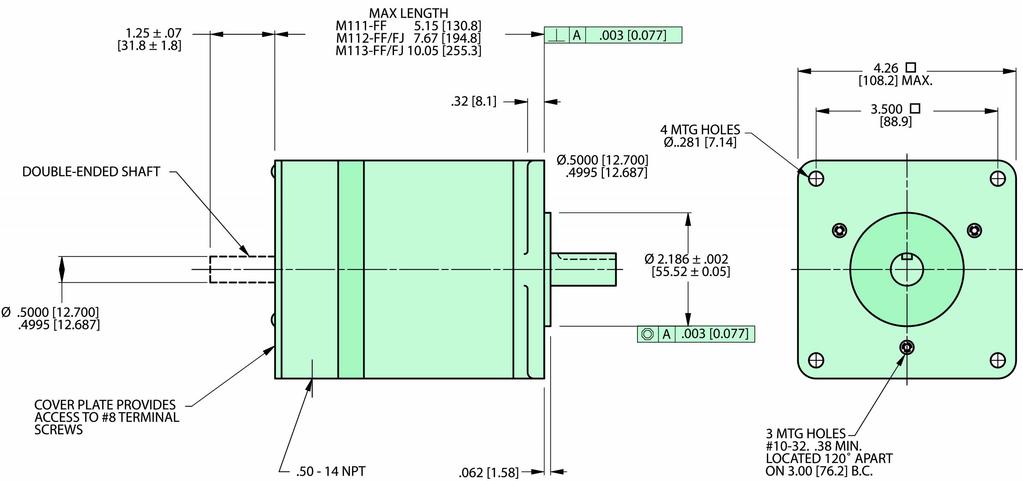
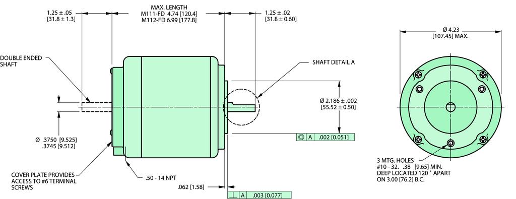
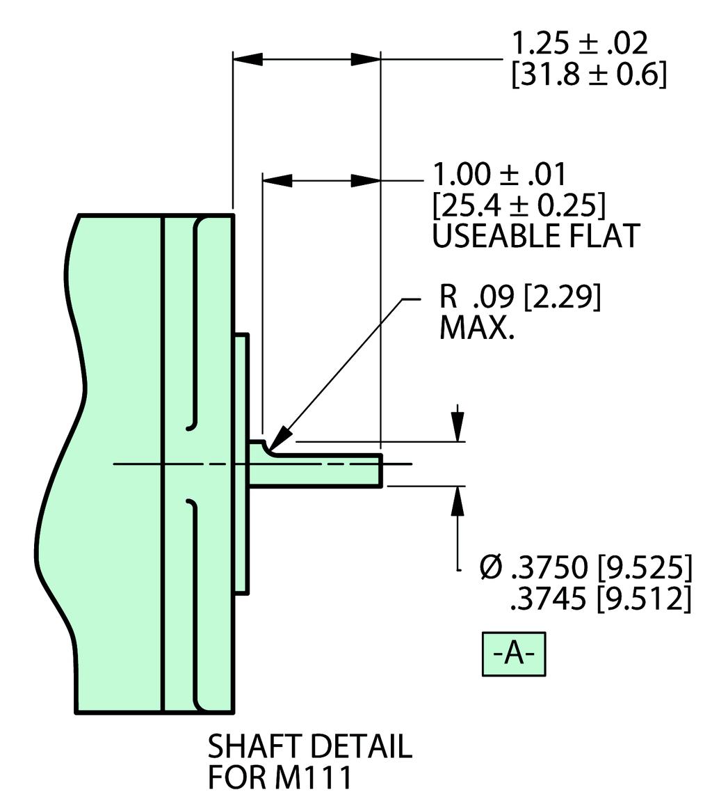
30 M11 Standard 11mm Frame Size (NEMA Size 42) Performance Envelope (see page DC34 for detailed torque-speed curves)! Up to 2% rated torque reserve capacity! ± 5% typical step accuracy! Standard terminal box, encoders, and `recision gearheads available! Available with four, six or eight connections! Customized configurations available Minimum Holding Torque Motor Frame Unipolar 2Ø on Bipolar 2Ø on M111 oz-in (Ncm) 625 (441) 1125 (794) oz-in (Ncm) 85 (6) 139 (981) M112 DC 3 Rotor Inertia oz-in-s2 (kg-cm2).55 (3.93).114 (8.6) Weight Maximum Shaft Load Net Ship Overhang Thrust Minimum Residual Torque lb (kg) 8. (3.63) 16.7 (7.57) lb (kg) 9.25 (4.2) 16.5 (7.4) lb (kg) 25 (11.3) 25 (11.3) lb (kg) 5 (22.7) 5 (22.7) oz-in (Ncm) 6 (4.24) 12 (8.47)
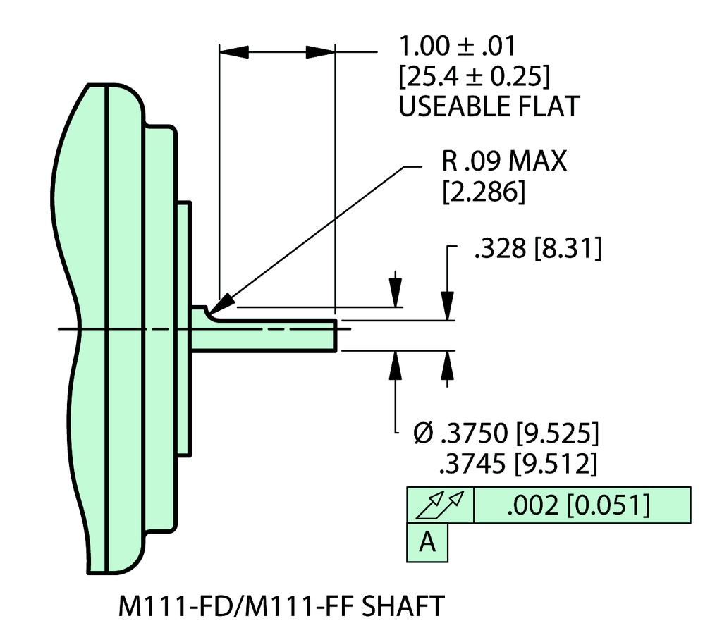
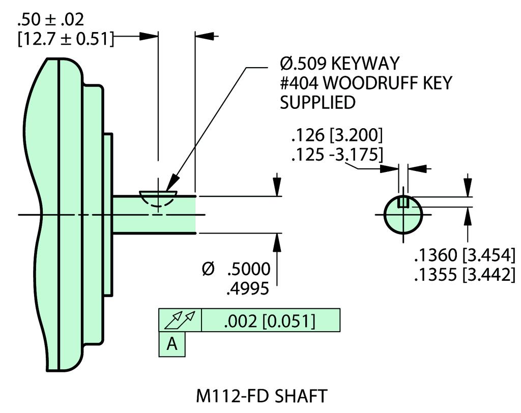
31 M 11 F 1 single stack 2 double stack 3 triple stack Identification Suffix (Coil Rating) D = 6 or 8 connections, round flange F = 4 connections, square flange* J = 6 or 8 connections, square flange, sealed against ingress or liquids or dust * NOTE: Except the M111-FF41 which has a round flange M11 Model Number See Next Page for Options 4-CONNECTION STEP MOTORS Winding Specifications Voltage Current Resistance Flange VDC Amperes ohms Inductance mh M111-FF-26 SQ M111-FF-41 R M112-FF-26 SQ M112-FF-41 SQ CONNECTION STEP MOTORS Model Number Winding Specifications Unipolar Bipolar Series See next page for options Flange Voltage VDC Current Amperes Resistance ohms Inductance mh Voltage VDC Current Amperes Resistance ohms Inductance mh M111-FD12 R M112-FD12 R Model Number See next page for options 8-CONNECTION STEP MOTORS Winding Specifications Unipolar Bipolar Series Bipolar Parallel Voltage Current Resistance Inductance Voltage Current Resistance Inductance Voltage Current Resistance Inductance Flange VDC Amps ohms mh VDC Amps ohms mh VDC Amps ohms mh M111-FD-812 R M112-FJ-812 SQ DC 31

32 Box Motor Dimensions (SQ Flange) M11Terminal (R Flange) DC 32
33 Encoder M11 DC 33
34 TORQUE - oz in TORQUE - oz in TORQUE - oz in SLO-SYN M11 17 V Bipolar - Microst ostep ep! Data measured with SS2D3, D6, or D12 Packaged Drive [1.8 Steps/Sec] (Ncm) 7 M111-FD-812 serial 6. A peak 494 M111-FD parallel A peak 5 M111-FF A peak 353 M111-FF A peak V Bipolar - Microst ostep ep! Data measured with SS2D12 Packaged Drive [1.8 Steps/Sec] (Ncm) M111-FF A peak 494 M111-FD series 6. A peak M111-FD A peak M Motor Speed (rps) Motor Speed (rps) [1.8 Steps/Sec] (Ncm) M112-FF A peak M112-FF A peak 12 M112-FF A peak 1 M112-FF A peak 76 8 M112-FJ-812 parallel 12. A peak 565 M112-FJ-812 series 6 6. A peak 424 TORQUE - oz in [1.8 Steps/Sec] (Ncm) 14 M112-FF A peak M112-FF A peak M Motor Speed (rps) Motor Speed (rps)! The curves do not show system resonances which will vary with system mechanical parameters.! Duty cycle is dependent on torque, speed, Drive parameters, and heat sink conditions. Maximum case temperature is 1 C. DC 34

 Current")
35 Hazardous Duty 11mm Frame Size! Up to 2% rated torque reserve capacity! ± 5% typical step accuracy! Hazardous Duty UL Class 1, Division 1, Group D MX11 Change U to EU for double ended shaft Dimensions 4-CONNECTION STEP MOTORS Model Number Winding Specifications Voltage (VDC) Current (Amperes) Resistance (ohms) Inductance (mh) MX111-FF-41U MX112-FF-41U DC 35
 without demagetization ± 5% typical step accuracy Available with four or eight connections Class F insulation system Standard keyway Rotor Inertia.133 oz-in-s 2 (9.")
36 MH112 High Torque 11mm Frame Size (NEMA Size 42) Performance Envelope (see page DC39 for detailed torque-speed curves) MH112 Specifications* Can withstand up to 2-1/2 times rated current (instantaneous) without demagetization ± 5% typical step accuracy Available with four or eight connections Class F insulation system Standard keyway Rotor Inertia.133 oz-in-s 2 (9.42 kg-cm 2 ) Weight (Net) 2.5 lbs. (9.3 kg) Weight (Ship) 24 lbs. (11 kg) Maximum Overhang Load 5 lbs. (23 kg) Maximum Thrust Load 1 lbs. (45 kg) Minimum Residual Torque 85 oz-in (6 Ncm) *Values shown are reference information. Parameters to be used as part of a specification should be verified with the factory. DC 36

37 Model Number Min. Holding Torque 2 On 4-CONNECTION STEP MOTORS Voltage (VDC) Winding Specifications Current (Amperes) Resistance (ohms) Inductance (mh) MH112-FF-26* MH112-FJ * Class B insulation system MH112 Model Number Min. Holding Torque 2Ø On Voltage (VDC) 8-CONNECTION STEP MOTORS Bipolar Series Winding Specifications Current Resistance Inductance (Amperes) (ohms) (mh) Voltage (VDC) Bipolar Parallel Current Resistance Inductance (Amperes) (ohms) (mh) MH112-FJ MH112-FJ Motor Dimensions DC 37

38 MH112 Encoder DC 38
39 TORQUE - oz in TORQUE - oz in SLO-SYN MH V Bipolar - Microst ostep ep! Data measured with SS2D3, D6, or D12 Packaged Drive [1.8 Steps/Sec] (Ncm) 18 MH112-FF A peak MH112-FF A peak MH112-FJ-82 series A peak 76 MH112-FJ A peak 565 MH Motor Speed (rps)! The curves do not show system resonances which will vary with system mechanical parameters. MH V Bipolar - Microst ostep! Data measured with SS2, or D12 Packaged Drive [1.8 Steps/Sec] (Ncm) 18 MH112-FF A peak MH112-FJ A peak MH112-FJ-82 series A peak Motor Speed (rps)! Duty cycle is dependent on torque, speed, Drive parameters, and heat sink conditions. Maximum case temperature is 1 C. DC 39
 533 oz-in.")
40 MH172 SLO-SYN High Torque 17mm Frame Size (NEMA Size 66) Performance Envelope (see page DC41 for detailed torque-speed curves)! Can withstand up to 2-1/2 time rated current (instantaneous)! ± 5% typical step accuracy! Available with eight connections! Class F insulation system! Standard keyway MH172 Specifications* Minimum Holding Torque (Bipolar 2Ø on) 533 oz-in. (3764 Ncm) Rotor Inertia.87 oz-in-s 2 (61.4 kg-cm 2 ) Weight (Net) 53 lbs. (24 kg) Weight (Ship) 62 lbs. (28 kg) Maximum Overhang Load 1 lbs. (45.4 kg) Maximum Thrust Load 15 lbs. (68. kg) Minimum Residual Torque 5 oz-in (35 Ncm) *Values shown are reference information. Parameters to be used as part of a specification should be verified with the factory. MH FD - 83 E = Rear Shaft Extension C2 = 2 line six output encoder C4 = 4 line six output encoder C5 = 5 line six output encoder DC 4
 Inductance (mh) Voltage (VDC) Current (Amperes) Resistance (ohms) Inductance (mh) MH172-FD83 SQ 3.25 1.6.31 8.5 1.6 21.77 2.")
41 TORQUE - oz in TORQUE - oz in SLO-SYN Motor Dimensions* 8-CONNECTION STEP MOTORS Winding Specifications Bipolar Series Bipolar Parallel Model Number Flange Voltage (VDC) Current (Amperes) Resistance (ohms) Inductance (mh) Voltage (VDC) Current (Amperes) Resistance (ohms) Inductance (mh) MH172-FD83 SQ MH172 * Encoder if applicable, fits inside terminal box 17 V Bipolar - Microst ostep! Data measured with SS2D3, D6, or D12 Packaged Drive 34 V Bipolar - Microst ostep! Data measured with SS2, or D12 Packaged Drive MH172 [1.8 Steps/Sec] (Ncm) 45 MH172-FD series 12. A peak MH172-FD-83 parallel A peak [1.8 Steps/Sec] (Ncm) 45 MH172-FD parallel 12. A peak MH172-FD-83 series A peak Motor Speed (rps) Motor Speed (rps)! The curves do not show system resonances which will vary with system mechanical parameters.! Duty cycle is dependent on torque, speed, Drive parameters, and heat sink conditions. Maximum case temperature is 1 C. DC 41

 3 = A, B and Index 6 = A, B, Index Shaft Size A, B, Index 25 = 1/4 Inch Diameter (with Differential Line Drivers) 38 = 3/8")
42 ENCODERSIncr Incr Increment emental Rot otar ary Optical Kit Encoders 2, 4, 5 lines per revolution 125 lines per revolution Dimensions ORDERING INFORMA ORMATION The following diagram explains the Encoder Kit number system: EK Note: 125 Lines per revolution Encoder Kit Number of Outputs 2 = Single-Ended (A, B only) Encoder Body Diameter (2.1 inches) 3 = A, B and Index 6 = A, B, Index Shaft Size A, B, Index 25 = 1/4 Inch Diameter (with Differential Line Drivers) 38 = 3/8 Inch Diameter Pulses Per Revolution: 2, 4, 5, 125 DC 42
43 Specifcations 2, 4, 5 Lines per rev 125 Lines per rev Mechanical Specifications Weight 2.1 ounces 6 ounces Moment of Inertia 2.6 x 1-4 oz-in-sec 2 max. 5. x 1-4 oz-in-sec 2 Bearing Life L 1 = 2 billion revolutions Acceleration 1, rad/sec 2 Bore Size.25 in. or.375 in. Slew Speed 15, rpm max. 7, rpm max. Strain Relief withstands 1 lb. pull on cable or wire bundle Motor Interface Mounting Holes 2 x #4-4 at 18 on a dia. bolt circle Perpendicularity (Shaft-to Mount).5 in. TIR Shaft Endplay.1 in..6 in. Shaft Diameter required.2495 /.25 in /.375 in. Minimum useable shaft length.56 in. Min. required.7 in. Electrical Spciifications Code Incremental Cycles per Revolution 2, 4, 5, as specified 125 Supply Voltage 5 VDC Output Format dual channel quadrature, 45 min. edge separation Output Format Options index and complementary ouputs square wave TTL compatible Output Type, Less Complements short-circuited protected capable of sinking 1mA Output Type, With Complements differential line drivers (26LS31) capable of sinking 2mA Frequency Response 1 khz Frequency Modulation.5% 5 khz 1% max. Frequency Accuracy 3. arc min. max. (zero runout) Environmental Specifications Operation Temperature -1 C to +8 C (less complements) -1 C to +1 C (with complements) C to + 85C Storage Temperature -2 C to +1 C (less complements) -4 C to +1 C (with complements) -3 C to +11 C Enclosure Unsealed housing, (must be protected from harsh environments) ENCODERS DC 43


44 GEARHEADS SLO-S O-SYN Gearheads Many applications need a higher torque or a smaller step angle than is possible by directly driving the load from the motor shaft. An ideal way to satisfy these requirements is by using a motor that has an integrally mounted gearhead. SLO-SYN DCGearheads are available in precision NEMA and Planetary models to meet the need for speed reduction without the problems associated with belts or pulleys. The wide range of available ratios assures a design solution for virtually any Motor with NEMA Gearhead application. The Gearheads can be supplied as a complete assembly with the Gearhead already NEMA Gearhead Kit mounted to a SLO-SYN motor, or as a kit for mounting to an existing motor. Both NEMA and Planetary types are offered with a clamp-on pinion for the motor shaft or with a pinion designed to Motor with NEMA Gearhead be pinned to the shaft for positive, permanent mounting. Planetary Gearhead on DC Stepper Motor Planetary Gearhead Kit DC 44
45 Gearhead Options and Ordering Information 6mm NEMA 23 Spur Gearheads S LB - M E-In Line R-Right Angle For Right Angle Only S-Single Output Shaft D-Double Output Shaft Gear Ratio 3-3:1 2-2:1 5-5:1 5-5:1 1-1:1 1-1: :1 Insert to order Low Backlash Unit 6mm NEMA 23 3 Planetar ary y Gearheads - All motors with.25 shaft except KM KM63 (.312 shaft) GEARHEADS P 23 - LB - M M- In Line T - Right Angle Insert to order Low Backlash Unit X - In Line Z - Right Angle Gear Ratio 5-5:1 1-1:1 2-2:1 5-5:1 1-1:1 5 - All motors with.25 shaft except KM In Line KM63 (.312 Shaft) 68 - Right Angle KM63 (.312 Shaft) DC 45
46 Gearhead Options and Ordering Information GEARHEADSGearhead Gearhead Op 9mm NEMA 3 9mm NEMA 34 Spur Gearheads S LB - M E-In Line R-Right Angle For Right Angle Only S-Single Output Shaft D-Double Output Shaft Gear Ratio 3-3:1 2-2:1 5-5:1 5-5:1 1-1:1 1-1: :1 Insert to order Low Backlash Unit 9mm NEMA 34 4 Planetar ary y Gearheads P 34 - LB - M - All M9 Motors (.375 Shaft) 16 - All KM9 Motors (.5 Shaft) M- In Line T - Right Angle Insert to order Low Backlash Unit X - In Line Z - Right Angle Gear Ratio 5-5:1 1-1:1 2-2:1 5-5:1 1-1:1 6 - In Line M9 Series (.375 Shaft) 2 - Right Angle M9 Series (.375 Shaft) 5 - All KM9 motors (.5 Shaft) DC 46
47 Gearhead Options and Ordering Information 11mm NEMA 42 Spur Gearhead S LB - M E-In Line R-Right Angle For Right Angle Only S-Single Output Shaft D-Double Output Shaft Gear Ratio 3-3:1 2-2:1 5-5:1 5-5:1 1-1:1 1-1: :1 Insert to order Low Backlash Unit 9mm NEMA 42 2 Planetar ary y Gearheads See Table Below All Motors with.625 Shaft 16 - All Motors with.375 Shaft GEARHEADS P 42 - LB - M M- In Line T - Right Angle Insert to order Low Backlash Unit X - In Line Z - Right Angle Gear Ratio 5-5:1 1-1:1 2-2:1 5-5:1 1-1: See Table Below In Line Motors with.625 Shaft In Line Motors with.375 Shaft Right Angle Motors with.625 Shaft Right Angle Motors with.375 Shaft Type Number Shaft Diameter M111-FF M111-FF M111-FD M111-FD M112-FD12 No Gearbox Option M112-FJ M112-FF M112-FF M113-FF DC 47

48 GEARHEADS New P Series s Planetar ary Gearheads 1.Planetary Output... Unique technology is built into the gearhead to deliver The Helical Advantage at the load-carrying output section. 2.Spiral Bevel Gears... Deliver high efficiency and high torque in a compact, right angle package. 3.High Speed Input... Helical gearing provides high input speeds with quiet operation. Input cavity surrounds the gears for constant lubrication in any orientation. 4.Patented Motor Mounting... Design ensures error-free installation and the balanced pinion allows higher input speeds. 5.Compact Design... 2 package lengths per frame size, 1 for ratios 1:1, 1 for > 1:1. Two lengths provides for a shorter packages for ratios 1:1. 6. IP65 Sealed Unit... Seals and O-Rings provide IP65 protection to prevent leaks and protect against harsh environments New P Series Planetary Gearheads are available as In-Line (PM Series) and Right Angle (PT Series) Models. They provide 3% more torque than their predecessors while operating faster, quieter, and with more accuracy. Specifications: Efficiency: PM Series = 9% PT Series = 92% Noise: With 3 RPM input speed, measured at 1 meter - 7dB Ratios: 5:1, 1:1, 2:1, 5:1, 1:1 Output Torque Backlash Rated Input Rated Rated Torque Model Peak (1)(2 ) Moment of Inertia Input Standard/Low No. in-lb (Nm) in-lb (Nm) in-lb (Nm) Speed oz-in-sec 2 (kg-m 2 ) arcminutes Stealth PM Performance Specifications PM23 3 (34) 6 6(8) Rated Output 5, 1.5 X 1-3 (1.1 X 1-5 ) 15/1 PM34 8 (9) 1,6 (18) Torque + Applicable 4, 3 X 1-3 (2 X 1-5 ) 15/1 PM42 1,6 (18) 3,2 (36) Ratio (3 ) 4, 7 X 1-3 (5 X 1-5 ) 15/1 Stealth PT Performance Specifications PT (41) 716 (82) 25 (2.8) 4, 1.7 x 1-3 (1.2 x 1-5 ) 1/6 PT (14) 1,832 (28) 75 (8.5) 4, 3.3 x 1-3 (2.2 x 1-5 ) 8/4 PT42 1,792 (23) 3,584 (46) 15 (17.) 4, 7.7 x 1-3 (5.5 x 1-5 ) 8/4 (1) Reduce ratings by 1% for 3:1, 1:1, 3:1, and 1:1 ratios (3) Ex: Rated Input Torque For a PM34 Gearhead with 5:1 Ratio = 9 Nm/5 = 18Nm (2) Peak torques not to exceed 5% of duty cycle. (8 in-lb/5 = 16 in-lb.) DC 48
49 Dimensions OUTPUT VIEW I R D B 4 Holes EQ. SP. on Ø C B.C. A B C D E F G H I J Square Bolt Bolt Pilot Output Shaft Output Shaft Pilot Flange Housing Housing Model Flange H ole Circle Diameter Diameter Length Thickness Thickness Diameter Recess No. in (mm) in (mm) in (mm) in (mm) in (mm) in (mm) in (mm) in (mm) in (mm) in (mm) PM (6).217 (5.5) (7) (5).63 (16).98 (25).98 (2.5).51 (13) 3.15 (8).197 (5.) PM (9).256 (6.5) (1) 3.15 (8).787 (2) 1.57 (4).118 (3.).67 (17) 4.57 (116).256 (6.5) PM (115).335 (8.5) (5.118 (13) (11).945 (24) 1.97 (5).138 (3.5).79 (2) 5.98 (152).295 (7.5) AD L1 L2 M N O P Q R Adapter Length Length D ist. F ro m Keyway Key Keyway Shoulder Shoulder Model (fo r R a tio 1 :1) (for Ratio > 1 :1) Shaft E n d Length H eight Width H eight D iam eter No. in (m m ) in (m m ) in) (m m ) in (m m ) in (m m ) in (m m ) in (m m ) in (m m ) in (m m ) )P M (3 3) 1.69 (43.) (73.).118 (3).63 (3).79 (18.).2 (5).4 (1.).87 (2 2) PM (3 6) (56.5) (96.) 1.97 (5) (5).8 86 (22.5).24 (6).4 (1.) 1.38 (3 5) PM (4 3) (67.8) (115.6).2 76 (7) (7) (27.).32 (8).6 (1.5) 1.38 (3 5) R C C S A O P J OUTPUT VIEW B SHAFT DETAILS FOR NEMA SIZES P O M O E M G N Q F SIDE VIEW O L H L I SIDE VIEW AD * AD N MOTOR INPUT MOTOR INPUT GEARHEADS J U D A H T Q P E G K F A B C D E F G H I J Square Bolt Bolt Pilo t OutputShaft OutputShaft Pilo t Flange Recess H o using Model Flange H ole C irc le D iam eter D iam eter Length Th ickness Th ickness Length Recess No. in (m m ) in (m m ) in (m m ) in (m m ) in (m m ) in (m m ) in (m m ) in (m m ) in (m m ) in (m m ) PT (6 ).2 17 (5.5) (7 ) (5 ).6 3 (1 6) 1.46 (3 7).2 76 (7).3 1 (8) (3 6).1 97 (5.) PT (9 ).2 56 (6.5) (1) 3.15 (8 ).8 66 (2 2) 1.89 (4 8).3 94 (1 ).3 94 (1 ) (5 ).2 56 (6.5) PT (11 5).3 35 (8.5) (13) (11 ) 1.26) (3 2) 2.56 (6 5).4 72 (1 2).4 7 (1 2) 2.48 (6 3).2 95 (8.) K L M N O P Q R S T U Dist. to Output Housing Housing Dist. to Inp u t Taper Dist. Fro m Keyway Keyway Keyway Shoulder Shoulder Model Centerline Le ng th Width Centerline Dist. Shaft End Le ng th Height Width Height Diam e ter No. in (m m ) in (m m ) in (m m ) in (m m ) in (m m ) in (m m ) in (m m ) in (m m ) in (m m ) in (m m ) in (m m ) )PT (66.) 3.78 (9 6 ) 2.87 (7 3 ) (43.).591 (1 5).79 (2 ).984 (2 5 ) (79 (18.) (.197 (5 ).59 (1.5).866 (2 2 ) P T (13.) (1 48) 4.5 (1 3) (58.).984 (2 5 ).118 (3 ) 1.26 (3 2 ).965 (24.5).236 (6 ).59 (1.5) 1.35 (3 5 ) P T (122.5) 7.9 (1 8) 5.8 (1 29) 2.81 (71.5) 1.26 (3 2 ).197 (5 ) (4 ) (35.) (.39 (1 ).8 (2.) 1.77 (4 5 ) * AD = Adapter Length: PT (1.); PT (1.); PT (1.5) SLO-SYN DC STEP MO- TORS DC 49

50 GEARHEADS S Series s NEMA Spur Gearheads 1.Low Backlash... 2 arcminutes standard (SE models) 3 arcminutes standard (SR models) 2.Quick, Easy Mounting... Special Clamp-On Pinion for easy motor mounting 3.High Efficiency... Precision spur gears raise efficiency above 92% 4.Mounts in any Orientation... Because they are grease-filled, the gearhead can be used in any orientation without messy oil leaks. 5.Long Life... Single piece construction gears and high strength aluminum alloy housing ensure long, reliable life. S Series NEMA spur gearheads are available as In-Line (SE series) and Right Angle (SR Series) models. They are designed to mount directly to the face of the motor. NEMA Gearheads are ideal for applications requiring smooth operation and low starting torque. Specifications: Efficiency: SE and SR Series = 92% Ratios: 3:1, 5:1, 1:1, 15:1, 2:1, 5:1, 1:1 Output Torque Backlash Rated Input Rated Rated Peak Torque Moment of Inertia Model Input Standard/Low No. in-lb (Nm) in-lb (Nm) in-lb (Nm) Speed oz-in-sec 2 (kg-m 2 ) arcminutes NEMA SE Performance Specifications SE23 5 (6) 1 (11) Rated Output 4, 7 X 1-5 (5 X 1-7 ) 2/1 SE34 25 (28) 5 (56) Torque + Applicable 4, 5 X 1-4 (4 X 1-6 ) 2/1 SE42 5 (56) 1, (112) Ratio (2 ) 4, 4 X 1-3 (3 X 1-5 ) 2/1 NEMA SR Performance Specifications SR23 5 (6) 1 (11) Rated Output 4, 8 x 1-5 (6 x 1-7 ) 3/15 SR34 25 (28) 5 (56) Torque + Applicable 4, 6 x 1-4 (4 x 1-6 ) 3/15 SR42 5 (56) 1, (112) Ratio (2 ) 4, 5 x 1-3 (3 x 1-5 ) 3/15 (1) Peak torques not to exceed 5% of duty cycle. (2) Ex: Rated Input Torque for an SE34 Gearhead with 5:1 Ratio = 28 Nm/5 = 5.6 Nm DC 5
51 Dimensions A B C D E F G H I Square Bolt Bolt Pilot Output Shaft Output Shaft Pilot Flange Housing Model Flange H ole Circle Diameter Diameter Length Thickness Thickness Diameter No. in (mm) in (mm) in (mm) in (mm) in (mm) in (mm) in (mm) in (mm) in (mm) SE (58).195 (5.) (66.7) 1.5 (38.1).375 (9.5) 1. (25.4).62 (1.6).19 (5) 3. (76) SE (83).218 (5.5) (98.4) (73.).5 (12.7) 1.25 (31.8).65 (1.7).38 (1) 4.38 (111) SE (17).281 (7.1) 4.95 (125.7) (55.5).625 (15.9) 1.5 (38.1).93 (2.4).5 (13) 5.63 (143) J K L M N O GEARHEADS Input Pilot Input Pilot Housing Keyway Keyway Keyway Model Diameter Depth Length Length Depth Width No. in (mm) in (mm) in (mm) in (mm) in (mm) in (mm) SE (38.1).125 (3.2) 2.3 (56).75 flat (19).15 flat (.4) SE (73.1).2 (5.1) 2.99 (76) 1.6 (27).72 (1.8).125 (3.2) SE (55.6).187 (4.7) 3.73 (95) 1.13 (29).18 (2.7).188 (4.8) A B C D E F G H I Square Bolt Bolt Output Pilot Output Shaft Output Shaft Output Pilot Flange Input Pilot Model Flange H ole Circle Diameter Diameter Length Thickness Thickness Diameter No. in (mm) in (mm) in (mm) in (mm) in (mm) in (mm) in (mm) in (mm) in (mm) SR (58).195 (5.) (66.7) 1.5 (38.1).375 (.95) 1. (25.4).62 (1.6).22 (6) 1.51 (38.1) SR (83).218 (5.5) (98.4) (73.).5 (12.7) 1.25 (31.8).65 (1.7).38 (1) (73.1) SR (18).281 (7.1) 4.95 (125.7) (55.5).625 (15.9) 1.5 (38.1).93 (2.4).5 (13) (55.6) J K L M N O P Q Input Pilot Dist. to Output Housi ng Housi ng DIst. to Input Keyway Keyway Keyway Model Depth Centerline Length Width Centerline Length Width Depth No. in (mm) in (mm) in (mm) in (mm) in (mm) in (mm) in (mm) in (mm) SR23.8 (2. ) 3.9 (78) 4.22 (17) 2.49 (63) 1.36 (35).75 flat (1 9) flat (. 4) SR34.2 (5.1) 4.33 (11) 5.96 (151) 3.63 (92) 2. (5 1) 1.13 (29).125 (3. 2).72 (1. 8) SR (4.7) 5.38 (137) 7.5 (191) 4.75 (121) 2.63 (67) 1.13 (29).188 (4. 8).18 (2. 7) DC 51
52 SLO-S O-SYN DC STEP MOTOR ORS - APPLICATION ASSISTANCE ANCE CONTENTS Table of Contents Page CAMAS Application Software 53 Leadscrew System 54 Cylinder/Rod System 55 Disc/Pulley System 56 Nip Roller System 57 Conveyor / Rack and Pinion System 58 Conveyor System 59 Motion Calculations 6 Tables Rotor Inertia for M Series 61 Rotor Inertia for KM Series 61 Density Table for Material 61 Coefficients of Static Friction Materials 62 Leadscrew Efficiencies 62 Conversion Factors 62 Technical Notes 64 Definitions 68 DC 52 APPLICATION ASSISTANCE
53 SLO-S O-SYN DC STEP MOTOR ORS - APPLICATION ASSISTANCE ANCE Sizing and Selection Software for Superior Electric SLO-SYN Products How to Select a Stepper Motor Successful application of a step motor requires careful selection of the proper step motor drive and control as well as the correct step motor. Since step motor systems are often used as ultra high performance positioning systems or motion controls, selection of the optimum motor/drive combination is of prime importance. The first step in the selection process is to decide the kind of system to use. Examples include Cylinder/Rod (solid or hollow), Lead Screw, Rack and Pinion, Disc/Pulley, Conveyer or Nip Rollers. A complete load analysis will be required to determine the correct motor size and the amount of torque needed to drive the load. Then it is necessary to determine which motor will best suit the application: Stepper Motor or Servo Motor. CAMAS software for Windows is a menu driven program which will make all these calculations for you. CAMAS is free software which is available upon request. CAMAS APPLICATION ASSISTANCE DC 53
 g = 386 in/sec 2 d = diameter (in) F = Force (lb) J = inertia (lb in 2 ) E = Efficiency (as a decimal) r = Screw lead (in/rev) w = weight of")
54 SLO-S O-SYN DC STEP MOTOR ORS - APPLICATION ASSISTANCE ANCE LEADSCREWS A. Leadscrew System: Variable Definitions: L = length (in) g = 386 in/sec 2 d = diameter (in) F = Force (lb) J = inertia (lb in 2 ) E = Efficiency (as a decimal) r = Screw lead (in/rev) w = weight of load (lb) Step 1: Calculate Load Inertia (J total load ): J load = w * ρ 2 *( ½ π) 2 J screw = π / 32 * d 4 * L * r or ½ * w * r 2 J total load = J load + J screw Step 2: Calculate Total Inertia (J total ): J total = J total load + J motor J motor is found in the Rotor Inertia table at the end of this section. Note: If J total load > 1 * J motor, then this motor will not be applicable. Step 3: Calculate the Torque in the System (T L ): For a Horizontal leadscrew application, the formula for the system torque is: T L = (F * ρ) / (E * 2π) For a Vertical leadscrew application, the formula for the system torque is: T L = (((g * w) +/- F) * ρ) / (E * 2π) where E is the efficiency of the system and F any force that opposes the movement of the load with the exception of friction or gravity. Step 4: Calculate the Torque Required to Obtain Base Speed (T b ): T b = J total * V b 2 *.32 Step 5: Calculate Torque Required to Accelerate the System (T a ): T a = J total ((V f V b ) / t acc )*.64 t acc is the rate of acceleration. DC 54 APPLICATION ASSISTANCE
 r i = inner radius (in) r o = outer radius (in) L = length (in) L = length (in) w = weight of cyl (lb) w = weight of cyl (lb) J = inertia")
 Hollow Cylinder: Inertia at Axis A: Inertia at Axis B: 2 J load = ½ * w(r o + r i2 ) 2 2 J load =")
: T L = F * r where F is the Force in Pounds.")
55 SLO-S O-SYN DC STEP MOTOR ORS - APPLICATION ASSISTANCE ANCE B. Cylinder/Rod System: Variable Definitions: r = radius (in) r i = inner radius (in) r o = outer radius (in) L = length (in) L = length (in) w = weight of cyl (lb) w = weight of cyl (lb) J = inertia (lb in 2 ) J = inertia (lb in 2 ) V b = Base speed (steps/sec) V b = Base speed (steps/sec) V f = Final speed (steps/sec) V f = Final speed (steps/sec) Step 1: Calculate Load Inertia (J load ): Solid Cylinder: Inertia at Axis A: Inertia at Axis B: J load = 1/2 * w * r 2 J load = 1/12 * w(3r 2 + L 2 ) Hollow Cylinder: Inertia at Axis A: Inertia at Axis B: 2 J load = ½ * w(r o + r i2 ) 2 2 J load = ¼ * w(r o + r i + h / 3) CYLINDER/ROD Step 2: Calculate Total Inertia (J total ) Very simply: J total = J load + J motor J motor is found in the Rotor Inertia table at the end of this section. Note: If J load > 1 * J motor, then this motor will not be applicable. Step 3: Calculate the Torque in System (T L ): T L = F * r where F is the Force in Pounds. Step 4: Calculate Torque Required to reach Base Speed (T b ): T b = J total * V b 2 *.32 Step 5: Calculate Torque Required to Accelerate the System (T a ): T a = J total ((V f V b ) / t acc )*.64 APPLICATION ASSISTANCE DC 55
 r 2 = radius load pulley (in) w 1 = weight motor pulley (lb) w 2 = weight load pulley (lb) F = Force required to rotate system")
56 SLO-S O-SYN DC STEP MOTOR ORS - APPLICATION ASSISTANCE ANCE DISC/PULLEY C. Disc/Pulley System: Variable Definitions: r 1 = radius motor pulley (in) r 2 = radius load pulley (in) w 1 = weight motor pulley (lb) w 2 = weight load pulley (lb) F = Force required to rotate system (lb) J = inertia (lb in 2 ) V b = Base speed (steps/sec) V f = Final speed (steps/sec) Step 1: Calculate Load Inertia (J total load ): 2 J motor pulley = 1/2 * w * r 1 J load pulley = 1/2 * w * r 2 2 J total load = J motor pulley + J load pulley Step 2: Calculate Total Inertia (J total ) J total = J total load + J motor J motor is found in the Rotor Inertia table at the end of this section. Note: If J total load > 1 * J motor, then this motor will not be applicable. Step 3: Calculate the Torque in System (T L ): T L = F * r 1 Step 4: Calculate Torque Required to reach Base Speed (T b ): T b = J total * V b 2 *.32 Step 5: Calculate Torque Required to Accelerate the System (T a ): T a = J total ((V f V b ) / t acc )*.64 DC 56 APPLICATION ASSISTANCE
57 SLO-S O-SYN DC STEP MOTOR ORS - APPLICATION ASSISTANCE ANCE D. Nip Roller System: Variable Definitions: F = Force (lb) J = inertia (lb in 2 ) r = radius (in) w = weight (lb) F = Force required to rotate system (lb) V b = Base speed (steps/sec) V f = Final speed (steps/sec) Step 1: Calculate Load Inertia (J total load ): NIP ROLLER Inertia of a roller or disc is calculated as: J roll = ½ * w * r 2 Repeat the above formula for each roller or disc that must be rotated as the load progresses. J total load = J spool + J roll 1 + J roll 2 + J roll 3 + J roll 4 etc Step 2: Calculate Total Inertia (J total ) J total = J total load + J motor J motor is found in the Rotor Inertia table at the end of this section. Note: If J total load > 1 * J motor, then this motor will not be applicable. Step 3: Calculate the Torque in System (T L ): T L = F * r Where r represents the radius of the roller or disc driven directly by the motor. Step 4: Calculate Torque Required to reach Base Speed (T b ): T b = J total * V b 2 *.32 Step 5: Calculate Torque Required to Accelerate the System (T a ): T a = J total ((V f V b ) / t acc )*.64 APPLICATION ASSISTANCE DC 57
58 SLO-S O-SYN DC STEP MOTOR ORS - APPLICATION ASSISTANCE ANCE CONVEYOR E. Rack and Pinion: Variable Definitions: w = weight of load (lb) r = radius of pinion gear (in) F = Force (lb) g = 386 in/sec 2 J = inertia (lb in 2 ) V f = Final speed (steps/sec) V b = Base speed (steps/sec) µ = Coefficient of friction between 2 surfaces. Step 1: Calculate Load Inertia (J total load ): J pinion = 1/2 * w * r 2 J rack = w * r 2 J total load = J pinion + J rack Step 2: Calculate Total Inertia (J total ) J total = J total load + J motor J motor is found in the Rotor Inertia table at the end of this section. Note: If J total load > 1 * J motor, then this motor will not be applicable. Step 3: Calculate the Torque in System (T L ): For or horizontally positioned Rack and Pinion applications, Torque for the system is calculated as: T L = w * µ * r The value for µ can be found on the Coefficient of Friction table at the end of this section. For vertically positioned Rack and Pinion applications, Torque for the system is calculated as: T L = ((g * w) + (w * µ)) r Step 4: Calculate Torque Required to reach Base Speed (T b ): T b = J total * V b 2 *.32 Step 5: Calculate Torque Required to Accelerate the System (T a ): T a = J total ((V f V b ) / t acc )*.64 DC 58 APPLICATION ASSISTANCE
59 SLO-S O-SYN DC STEP MOTOR ORS - APPLICATION ASSISTANCE ANCE F. Conveyer System: Variable Definitions: w = weight (lb) J = inertia (lb in 2 ) V f = Final speed (steps/sec) Step 1: Calculate Load Inertia (J total load ): J motor roll = ½ * w motor roll * r motor roll 2 J driven roll = ( ½ * w driven roll *r driven roll2 ) / (r driven roll / r motor roll ) 2 J belt = w belt * r motor roll 2 J load = w load * r motor roll 2 r = radius (in) V b = Base speed (steps/sec) F = Force required to move the system (lb) CONVEYOR Additional driven roll inertias must be added to the calculation as required. J total load = J motor roll + J driven roll + J belt + J load Step 2: Calculate Total Inertia (J total ) J total = J total load + J motor J motor is found in the Rotor Inertia table at the end of this section. Note: If J total load > 1 * J motor, then this motor will not be applicable. Step 3: Calculate the Torque in System (T L ): T L = F * r Where r represents the radius of the roller or disc driven directly by the motor. Step 4: Calculate Torque Required to reach Base Speed (T b ): T b = J total * V b 2 *.32 Step 5: Calculate Torque Required to Accelerate the System (T a ): T a = J total ((V f V b ) / t acc )*.64 APPLICATION ASSISTANCE DC 59
60 SLO-S O-SYN DC STEP MOTOR ORS - APPLICATION ASSISTANCE ANCE CALCULATIONS Motion Calculations (applicable to all configurations): Enter Required Torque: Enter value from Step 5 for your particular system. Determine available torque at required Velocity by referring to Speed/Torque Curve of the motor. oz in oz in If Available Torque is greater than Required Torque, then the motor is acceptable. Duty cycle considerations must be evaluated for proper motor selection. DC 6 APPLICATION ASSISTANCE
61 SLO-S O-SYN DC STEP MOTOR ORS - APPLICATION ASSISTANCE ANCE Required Tables: Rotor Inertia (for M series) Model: Inertia (lb in 2 ) Model: Inertia (lb in 2 ) M61.4 M93.64 M62.8 M M63.11 M M91.23 M M92 42 MH M MH TABLES Rotor Inertia (for KM series) Model: Inertia (lb in 2 ) Model: Inertia (lb in 2 ) KM6.369 KM KM KM KM KM KM Density Table for Material: Material Density (lb/in 3 ) Material Density (lb/in 3 ) Acryl.433 Iron (cast).2635 Aluminum.975 Magnesium.614 Bakelite.469 Nickel.3177 Brass.369 Nylon.412 Bronze.3213 Rubber.433 Copper.3213 Steel.2816 Glass.939 Teflon.794 Iron.2852 APPLICATION ASSISTANCE DC 61
62 SLO-S O-SYN DC STEP MOTOR ORS - APPLICATION ASSISTANCE ANCE TABLES Coefficients of Static Friction Materials: (Dry contact unless noted) Steel on Steel.58 Steel on Steel (lubricated).15 Aluminum on Steel.45 Copper on Steel.22 Brass on Steel.19 Teflon on Steel.4 Leadscrew Efficiencies: Type High Median Low Ball Nut Acme with metal nut ** Acme with plastic nut **Since metallic nuts usually require a viscous lubricant, the coefficient of friction is both speed and temperature dependant. Conversion Table To convert from A to B multiply by conversion factor. Divide to convert from B to A. A B oz-in kg-cm 2 INERTIA oz-in lb-in 2 lb-in kg-cm 2 oz-in.625 lb-in TORQUE oz-in.762 N-cm lb-in 11.3 N-cm WEIGHT lb.4536 kgf rpm steps/sec 1 ROTATIONAL rps 2 steps/sec SPEED rad/sec steps/sec 1 1 for 2 steps per revolution DC 62 APPLICATION ASSISTANCE
63 SLO-S O-SYN DC STEP MOTOR ORS - APPLICATION ASSISTANCE ANCE Application notes NOTES APPLICATION ASSISTANCE DC 63

64 TECHNICAL Characteristics of SLO-SYN DC Step Motors Brushless, permanent magnet motors Operate in full-step (1.8 ) or half-step (.9 ) increments Can be microstepped to achieve increments as small as.72 Accuracies typically ±2% or ±3% for size 23 and 34 motors. (For larger motors it is ±5%) (1) Can be operated at rates to 2, steps per second (6 rpm) Holding torque ratings from 54 to 533 oz-in (38 to 3764 Ncm) Wide range of torque ratings, shaft configurations and frame sizes Easily adapted to different control types, including microprocessor based systems Class B insulation, operate at ambient temperatures from -4 C to +65 C (-4 F to +149 F) No brushes, ratchets or detents to wear out Lubricated-for-life ball bearings (1) Maximum positive or negative deviation from the rated angular motion per step, for any step in a complete revolution. Expressed as a percentage of the angle of a single step. Measured at no load with rated current applied to both motor windings (balanced to within 1%) and motor operated in the two windings on mode. Underwriters Laboratories Recognition & Canadian Standards Association Certification and CENELEC Certification All M6, KM6 and M9, KM9 Series motors are recognized by UL, UL#E31544 KM6 and KM9 Series motors carry the CE mark Most standard motors are listed by Canadian Standards Association, including all M6 and M9 Series Motors Motors in other series which meet UL requirements are identified with letter U suffix or are provided with a UL logo. Most standard motors, as well as double end motors, are eligible Comparison of Servomotors versus DC Step Motors Too often, when a motion control system is being specified, the designer automatically assumes that a servomotor system must be used. The truth is that, in many cases, a well designed step motor system will perform the same function as well, and at lower cost. The following comparison of the outstanding characteristics of the two types of motors outlines some of the advantages of step motors for motion control. Servomotor Characteristics Require complex, expensive control systems Position sensing devices needed for feedback to control Relatively low torque for size Thermally inefficient Control system must be tuned to load; must be retuned if load is changed Brushes on DC servomotors subject to wear SLO-SYN DC Step Motor Characteristics Relatively inexpensive Can be operated open-loop (no position feedback required) Noncumulative step error Simple control electronics can be used Brushless construction aids reliability Maintenance free Will not be damaged if stalled High torque for size Maintain position when at rest Call Superior Electric for a copy of Superior Motion Control Application Solutions, a user s guide to applying step motors and controls. Construction of DC Step Motors A SLO-SYN Step Motor is a brushless DC motor consisting of a rotor and a stator assembly. The illustration shows the internal construction and tooth alignment of the motor. A certain number of teeth, evenly spaced around the entire diameter, provide the incremental angular rotation that results in mechanical motion. SLO-SYN steps motors are constructed with a 48-5 or a 52-5 tooth pitch configuration. The second number, 5, refers to the number of teeth on the rotor. The 5 teeth, combined with the winding configuration and permanent magnet construction, deliver a 1.8 step angle. Both configurations have a slightly different tooth pitch on the stator (48 or 52) to provide smoother operation and softer step-to-step motion with less resonance or mechanical instability at low speed. The 52 tooth stator design is used in the new KM6 and KM9 motors to provide extra torque. Superior Electric held the original patent on the 48-5 design. DC 64
KM SERIES HIGH TOR.
 SLO-S O-SYN KM SERIES HIGH TOR ORQUE STEP ORS KM SERIES Superior Electric SLO-SYN long recognized as the leader in step motor technology, has achieved new levels of performance with its high energy KM
43M4 n n n n n n. 43L4 n n n n n n. E43M4 n n n n n n. Bipolar 5 VDC 12 VDC. 550 ma 1.3 A 21.9 Ω 3.8 Ω mh mh W Total.
 HAYD: 2 756 744 KERK: 6 2 629 4 Series: Double Stack Stepper Motor Linear Actuator Haydon 4 Series Double Stack hybrid linear actuators offer greater performance. Double Stack Captive Shaft The versatile
!Linear & Rotary Positioning Stages. !Servo Motors & Drives. !Gearmotors & Gearheads. GM Series Stealth Planetary Gearmotor Product Manual
 !Linear & Rotary Positioning Stages!Servo Motors & Drives!Gearmotors & Gearheads GM Series Stealth Planetary Gearmotor Product Manual GM Series Stealth Planetary Gearmotor Product Manual Rev: 7.0 / 0305
Kollmorgen Stepper Motor Overview
 Kollmorgen Stepper Motor Overview K O L L M O R G E N S T E P P E R M O T O R O V E R V I E W Kollmorgen offers a comprehensive range of stepper motor products including continous torque, high torque and
Rotary Series Rotary Series: Direct Drive Precision Stages
 Rotary Series Rotary Series: Direct Drive Precision Stages Parker Bayside s Direct Drive Rotary Stages feature a robust construction and high performance in a compact package, providing smooth, near-frictionless
Ultra Series: Crossed Roller Ultra Precision Stages
 Ultra Series: Crossed Roller Ultra Precision Stages Bayside Motion Group, has developed Ultra Positioning Stages for applications requiring the ultimate in accuracy. Available with a linear motor, ball
Servo Motors. Unimotor hd, Unimotor fm, NT Series and XV Series lb-in ( Nm) 230 V 460 V
 230 V 460 V") Servo Motors Unimotor hd, Unimotor fm, NT Series and XV Series 0.9-1204 lb-in (0.11-136 Nm) 230 V 460 V Contents Introduction: A Servo Motor for Every Application... 1 Drive and Motor Selection... 3 Electronic
Servo Motors Unimotor hd, Unimotor fm, NT Series and XV Series 0.9-1204 lb-in (0.11-136 Nm) 230 V 460 V Contents Introduction: A Servo Motor for Every Application... 1 Drive and Motor Selection... 3 Electronic
PRODUCT OVERVIEW HIGHEST PRECISION
 PRODUCT OVERVIEW If you need high precision gear reducers at a reasonable cost and you value innovation and excellent service, take a close look at our product line. You ll find a wide range of products
Courtesy of Steven Engineering, Inc - (800) PATENTED
 PATENTED") PRECISION RING DRIVE SYSTEMS Based on Nexen s innovative Roller Pinion technology, Nexen Ring Drive Systems come complete with a precision grade, high capacity bearing and drive mechanism in a rigid housing.
PRECISION RING DRIVE SYSTEMS Based on Nexen s innovative Roller Pinion technology, Nexen Ring Drive Systems come complete with a precision grade, high capacity bearing and drive mechanism in a rigid housing.
TRUE Planetary Gearheads
 Toll Free Fax (877) SERV99 TRUE Planetary Gearheads TRUE Planetary Gearheads Product Overview... 4 ue Planetary Gearheads... 6 Helical Crowned ue Planetary Gearheads... 7 PowerTRUE Right Angle Gearheads...
Hybrid Stepper Motors
 DINGS Electrical & Mechanical Co., Ltd 3 Quality Performance Flexibility Price WHO IS DINGS? DINGS is a premier supplier of rotary and linear step motors. Based in the greater Shanghai, China area, we
Step Motor Drive Products
 Step Motor Drive Products Danaher Motion and Superior Electric Superior Electric is a Danaher Motion brand and is recognized worldwide as the leading manufacturer of step motor drives. Over 40 years ago,
model HP Servo AccuDrive Family of Products
 model 09090.01 AccuDrive Family of Products Series W Model RG Series S Series P Series E/LE ACCUDRIVE PRECISION PRODUCTS Now you can get design flexibility and lasting performance from our complete family
GEARHEADS: STEALTH PLANETARY AND NEMA SPUR. Toll Free Phone (877) SERVO98 Toll Free Fax (877) SERV099
 SERVO98 Toll Free Fax (877) SERV099") GEARHEADS: STEALTH PLANETARY AND NEMA SPUR 184 Toll Free Fax (877) SERV99 Gearheads Stealth Planetary Gearheads 188 PS Advanced In-Line 196 PX In-Line 2 PV Power & Versitility 28 RS Advanced Right Angle
GEARHEADS: STEALTH PLANETARY AND NEMA SPUR 184 Toll Free Fax (877) SERV99 Gearheads Stealth Planetary Gearheads 188 PS Advanced In-Line 196 PX In-Line 2 PV Power & Versitility 28 RS Advanced Right Angle
PS/PX/RS/RX Series Stealth Generation II Precision Planetary Gearheads
 PS/PX/RS/RX Series Stealth Generation II Precision Planetary Gearheads Gen II Gearheads Provide Higher Radial Load, Increased Service Life and Ease of Mounting Features & Benefits Higher radial load capacity:
NEW. Linear Ball Bushing Bearings and 60 Case Shafting. Profile Rail Linear Guides
 Linear Ball Bushing Bearings and 60 Case Shafting Thomson invented the ball bushing bearing over 60 years ago and has since been the recognized leader in this field. Our linear products provide low friction,
AC Servo Motors and Servo Rated Gearheads
 AC Servo Motors and Servo Rated Gearheads for the automation industry Brushless Servo Motors 2 AC Servo Motors Baldor has been leading the way in energy efficient industrial motors since the 192 s. Baldor
Brushless. Motors. Drives. RapidPower Series E-Series EXC-Series. EA-Series SC-Series ACS-Series ACE-Series PFC-Series.
 Catalog EC3EN Brushless Motors Drives www.electrocraft.com RapidPower Series E-Series EXC-Series EA-Series SC-Series ACS-Series ACE-Series PFC-Series Toll Free Fax (877) SERV99 www.electrocraft.com For
Scroll down to view your document!
 Over 1 years cumulative experience 24 hour rush turnaround / technical support service Established in 1993 The leading independent repairer of servo motors and drives in North America. Visit us on the
Identifying the Motorized RGS part number codes when ordering
 RGS04 Motorized with 28000 Series Size11 DS RGS04 Linear Rail for Hybird 28000 Series Size 11 Double Stacks and RGS04 for 43000 Series Size 17 Single and Double Stacks (See Page 4) RGS04 Linear Rail with
Tandler. ServoFoxx Servo Gearheads
 Tandler ServoFoxx Servo Gearheads ServoFoxx Inline and Right Angle Planetary Servo Gearheads The Tandler ServoFoxx series of servo gearheads provide the ultimate in precision motion control for highly
Daedal Precision Gearheads
 Daedal Catalog 8085/US Introduction Quality, Performance, Reliability Parker are planetary gear reducers designed to excel in today s demanding servo motor applications. They offer a vast array of selectable
Screw Driven automation tables
 automation tables Precise multi-axis positioning systems play an integral part in today s semiconductor, computer peripheral, solar power, flat panel, life sciences, lab automation, biomedical and electronics
Product Overview. Hansen Precision Electric Motors DC AC DC. Actuators. Stepper
 AC Hansen Precision Electric Motors Hansen s quality products are known around the world. These include: Synchron Motors, available with custom voltage, speed and power, durable brush motors, AC clock
Standard Street, El Segundo CA BRUSHLESS SERVO MOTORS
 BRUSHLESS SERVO MOTORS To accommodate your complete servo system requirements, Glentek manufactures four complete series (GMB, GMBF, GMBM and GMBN) of high performance, permanent magnet brushless servo
Ø 68 mm to ø 115 mm. Material: Weight: Shaft Loads: Enclosure Rating: Connection Options. Cable: Cable Glands:
 Electrical Specifications Code: Incremental Resolution: Up to 10,000 ppr (pulses per revolution) Supply Voltage: ** 4.5 Vdc min. to 30 Vdc max. (45 ma max. - no load) Low: 500 mv max. at 10 ma Voltage:
Servo Motors & Drives. Gearmotors & Gearheads. Linear & Rotary Positioning Stages. Luge LM Product Manual
 Servo Motors & Drives Gearmotors & Gearheads Linear & Rotary Positioning Stages Luge LM Product Manual Luge LM Precision Linear Stage Product Manual Rev: 2.5 / 62005 P/N: 12197017 Please check www.baysidemotion.com
Ø 68 mm to ø 115 mm. Material: Weight: Bearing Life: Shaft Loads: Operating Temp.: Storage Temp.: Shock: Vibration: Bump: Humidity: Enclosure Rating:
 , EN 60079 Electrical Specifications Code: Incremental Resolution: Up to 10,000 ppr (pulses per revolution) Supply Voltage: ** 4.5 Vdc min. to 30 Vdc max. (45 ma max. - no load) Low: 500 mv max. at 10
SLM/SLG SERIES. SLM Series Motors/SLG Series Gearmotors BRUSHLESS AC OR DC SERVO MOTOR / INTEGRATED SERVO GEARMOTOR
 SLM Series Motors/SLG Series Gearmotors SLM/SLG SERIES BRUSHLESS AC OR DC SERVO MOTOR / INTEGRATED SERVO GEARMOTOR Compatible with virtually any manufacturer s servo drive Multiple frame size options 952.5.62
Silencer Series Brushless DC Motors
 TYPICAL APPLICATIONS Medical equipment - pumps, blowers and electric scooters and wheelchairs Automatic door and window openers Computer-controlled embroidery machines Scanners Packaging equipment and
Unimotor fm 230 V 460 V Unimotor fm 230 V / 460 V
 Unimotor fm 230 V 460 V Unimotor fm 230 V / 460 V Flexible Configuration C Servo Motors Flexible Configuration C Servo Motors Unimotor fm is a high performance, brushless C Servo motor range matched for
Catalog EC02EN. Brushless DC. Motors. Drives. EA-Series SC-Series. RapidPower Series E-Series EXC-Series.
 Catalog EC2EN Brushless DC Motors Drives RapidPower Series E-Series EXC-Series EA-Series SC-Series www.electrocraft.com www.electrocraft.com For over 6 years, ElectroCraft has been helping engineers translate
Stepper Motors. Wide Range of Motor Sizes! Motor Wiring D-1
 Stepper Motors Frame Sizes From NEMA 11 to 34 Wide Range of Motor Sizes! All models shown smaller than actual size. Motor Wiring OMEGA offers a robust line of 2-phase biploar step motors ranging in frame
Optical Kit Encoder Page 1 of 10. Description. Related Products & Accessories. Features
 Description Page 1 of 10 The E2 is a rotary encoder with a molded polycarbonate enclosure, which utilizes either a 5-pin locking or standard connector.this optical incremental encoder is designed to easily
MOONS SM servo motors offer a great combination of Power, Precision and Value:
 MOONS SM Series of servo motors has been expanded and improved. The SM Series now includes a variety of standard windings, more feedback options, and more connection options. Some ratings have increased,
Highest Performance: Dyna Series
 Highest Performance: Dyna Series GAM can. If you don t see exactly what you need, let us know. We can modify the Dyna Series gearboxes to meet your needs. Page provides a list of commonly requested modifications
The STH is a mid-range speed and torque gear reducer that
 -SERIES The is a mid-range speed and torque gear reducer that sets a new standard for rotary positioning performance at an exceptional price point. A SHIMPO ABLE planetary gearbox is the interface between
Highest Performance: Dyna Series
 Highest Performance: Dyna Series The Dyna Series is our highest performance right-angle gear reducer utilizing sophisticated hypoid gearing. The benefit of hypoid gearing is that it combines the space
Precision Gear Technology Guide
 Precision Gear Technology Guide NIDEC-SHIMPO CORPORATION Our Company NIDEC-SHIMPO has established itself as the leading supplier of precision gearing solutions to the industrial automation marketplace.
1326AS Series 460V, Low Inertia, Brushless Servo Motors Product Data
 1326AS Series 46V, Low Inertia, Brushless Servo Motors Product Data This publication provides product information for the.49 to 49.3 N-m (4.33 to 436 lb-in.) 1326AS Series 46V, Low Inertia, Brushless Servo
Highest Precision: Dyna Series
 Highest Precision: Dyna Series GAM can. Just ask! If you don t see exactly what you need, let us know. We can modify the Dyna Series gearboxes to meet your needs. Page 3 provides a list of commonly requested
300 & 400 Series Positioning Tables
 300 & 400 Series Positioning Tables 300 Series Introduction L-2 400 Series Introduction L-3 Specifications L-5 300 Series Dimensions L-6 400 Series Dimensions L-7 300 Series Motor Couplings L-8 300 Series
PC-Series Precision Linear Actuators. Optimize Your Machine and Save Energy With Reliable, High Performance, Compact Actuators
 PC-Series Precision Linear Actuators Optimize Your Machine and Save Energy With Reliable, High Performance, Compact Actuators Make the Change to Electric Enjoy superior performance and save time and energy
Material: Weight: Shaft Loads: Enclosure Rating: Cable: Cable Glands:
 Oil & Gas / Heavy Industry Type 2REX-A EN 60079 Electrical Specifications Code: Incremental Resolution: 1 to 10,000 ppr (pulses per revolution) Supply Voltage: ** 4.5 Vdc min. to 30 Vdc max. (45 ma max.
TRUE Planetary Gearheads
 TRUE Planetary Gearheads Danaher Motion - Helping you build a better machine, faster Danaher Corporation combined over 3 industry-leading brands such as Kollmorgen, Thomson, Dover, Pacific Scientific,
Highest Precision: SPL Series
 Highest Precision: SPL Series GAM can. Just ask! If you don t see exactly what you need, let us know. We can modify the SPL Series gearboxes to meet your needs. Page 3 provides a list of commonly requested
Kinetix Rotary Motion Specifications
 Technical Data Kinetix Rotary Motion Specifications Kinetix VP, MP-Series, Kinetix 6000M, TL-Series, HPK-Series, RDD-Series Topic Page Topic Page Kinetix VP Low Inertia Motors 2 Kinetix 6000M Integrated
Highest Precision: Dyna Series
 GAM can. Just ask! If you don t see exactly what you need, let us know. We can modify the Dyna Series gearboxes to meet your needs. Page 3 provides a list of commonly requested modifications to give you
POSITIONING STAGES AND SYSTEMS
 POSITIONING STAGES AND SYSTEMS DEVELOPING HIGHLY ENGINEERED LINEAR POSITIONING SYSTEMS THAT IMPROVE PRECISION, INCREASE PRODUCTIVITY AND CREATE VALUE FOR CUSTOMERS Linear and Rotary Positioning Stages
Type 2REX-A. Oil & Gas / Heavy Industry
 Oil & Gas / Heavy Industry Type 2REX-A EN 60079 Electrical Specifications Code: Incremental Resolution: 1 to 10,000 ppr (pulses per revolution) Supply Voltage: ** 4.5 Vdc min. to 30 Vdc max. (45 ma max.
HARMONIC GEARHEAD. Features & Benefits Specifications... 53
 HARMOIC GEARHEAD exen s revolutionary (HG) is the perfect combination of size and precision. Use the integrated with exen s RPS Pinion (HGP) to create a true backlash-free solution from the motor to the
Data Sheet. Size 1 and 2 Stepper Motors. 7.5 stepper motors Size 1 (RS stock no ) Size 2 (RS stock no ) Data Pack B
 Size 2 (RS stock no ) Data Pack B") Data Pack B Issued November 005 1504569 Data Sheet Size 1 and Stepper Motors 7.5 stepper motors Size 1 (S stock no. 33-947) Size (S stock no. 33-953) Two 7.5 stepper motors each with four 1Vdc windings
Data Pack B Issued November 005 1504569 Data Sheet Size 1 and Stepper Motors 7.5 stepper motors Size 1 (S stock no. 33-947) Size (S stock no. 33-953) Two 7.5 stepper motors each with four 1Vdc windings
Gearheads and Gearmotors
 aerospace climate control electromechanical filtration fluid & gas handling hydraulics pneumatics process control sealing & shielding Gearheads and Gearmotors Parker Hannifin Corporation A Fortune 300
LS100 Series Positioning Tables
 LS100 Series Positioning Tables User s Guide A N A H E I M A U T O M A T I O N 4985 East Landon Drive Anaheim, CA 92807 e-mail: info@anaheimautomation.com (714) 992-6990 fax: (714) 992-0471 website: www.anaheimautomation.com
TRUE Planetary Gearheads
 TRUE Planetary Gearheads Danaher Motion - Helping you build a better machine, faster Danaher Corporation combined over 3 industry-leading brands such as Kollmorgen, Thomson, Dover, Pacific Scientific,
K Series Kit Motor Reliable and Compact Approach: Build your own high-performance motor
 Frameless K Series Kit Overview K Series Kit Motor Reliable and Compact Approach: Build your own high-performance motor Direct drive motion construction gives equipment designers the advantages of lower
 --554-6 www.microngearheads.com Mechanical and Electro-Mechanical Product Solutions by Danaher Motion Danaher Motion engineers, manufactures and markets a select combination of the world s top brands of
MANTECH ELECTRONICS. Stepper Motors. Basics on Stepper Motors I. STEPPER MOTOR SYSTEMS OVERVIEW 2. STEPPING MOTORS
 MANTECH ELECTRONICS Stepper Motors Basics on Stepper Motors I. STEPPER MOTOR SYSTEMS OVERVIEW 2. STEPPING MOTORS TYPES OF STEPPING MOTORS 1. VARIABLE RELUCTANCE 2. PERMANENT MAGNET 3. HYBRID MOTOR WINDINGS
TurboDisc Stepper Motors
 TurboDisc Stepper Motors P43 P532 P31 P11 P1 The TurboDisc provides exceptional dynamic performance unparalleled by any other stepper on the market. The unique thin disc magnet enables finer step resolutions
Screw Driven automation tables
 automation tables Precise multi-axis positioning systems play an integral part in today s semiconductor, computer peripheral, solar power, flat panel, life sciences, lab automation, biomedical and electronics
KL-8070D. Fully Digital Stepping Driver. Table of Contents 1. Introduction, Features and Applications...1 Introduction...1 Features...
 Contents KL-8070D Fully Digital Stepping Driver Attention: Please read this manual carefully before using the driver! I Table of Contents 1. Introduction, Features and Applications...1 Introduction......1
Gearmotors & Gearheads. Servo Motors & Drives. Linear & Rotary Positioning Stages. Direct Drive Rotary Table Product Manual
 Servo Motors & Drives Gearmotors & Gearheads Linear & Rotary Positioning Stages Direct Drive Rotary Table Product Manual Direct Drive Rotary Table Product Manual Rev: 3.2 / 1103 P/N: 12197009 Please check
planetroll Planetary Gearheads
 planetroll Planetary Gearheads www.diequa.com 630-980-1133 Overview Planetary Servo Gearheads by Planetroll German Engineered - Ecomically Priced The Planetdrive series of precision planetary servo gearheads
Brushless Servo Motors
 Quantum QB56 Series Housed Brushless Servo Motors NEMA Size 56 High Power Density, Sinusoidal BEMF Allied Motion s Quantum (QB) housed brushless servo motors are designed for use in precision servo applications
A K M S E R V O M O T O R S. AKM Servo Motors
 A K M E R V O M O T O R AKM ervo Motors If you require precise position control, Kollmorgen's wide range of servo motors is certain to offer you the right solution. Our uniquely broad product range provides
MP-Series Food Grade Motors
 MP-Series Food Grade Motors MP-Series (Bulletin MPF) food-grade motors combine the characteristics of the MP-Series low-inertia servo motors with features specifically designed to meet the unique needs
Now you can get design flexibility and lasting performance from our complete family of AccuDrive Precision Products.
 ACCUDRIVE PRECISION PRODUCTS Now you can get design flexibility and lasting performance from our complete family of AccuDrive Precision Products. Series W Precision Servo Gearhead Output torque up to 8,500
Direct Drive Rotary An Increasingly Attractive Servo Choice
 Direct Drive Rotary An Increasingly Attractive Servo Choice DDR systems are available in frameless, housed and the newly developed Cartridge motor format. While many engineers are familiar with the basics
!Servo Motors & Drives. !Gearmotors & Gearheads. !Linear & Rotary Positioning Stages. Ultra Series Product Manual
 !Servo Motors & Drives!Gearmotors & Gearheads!Linear & Rotary Positioning Stages Ultra Series Product Manual Ultra Series Product Manual Rev: 1 / 904 Please check www.baysidemotion.com for latest revisions.
High Performance: EPR Series
 High Performance: EPR Series GAM can. If you don t see exactly what you need, let us know. We can modify the EPR Series gearboxes to meet your needs. Page 4 provides a list of commonly requested modifications
BMS Series. DC Brushless Torque Motors. Slotless, brushless stator design provides zerocogging torque for unsurpassed velocity control
 BMS Series Rotary Motors BMS Series DC Brushless Torque Motors Slotless, brushless stator design provides zerocogging torque for unsurpassed velocity control Smoother velocity than with standard DC brushtype
User s Manual. For DM542T. Full Digital Stepper Drive
 User s Manual For DM542T Full Digital Stepper Drive Designed by StepperOnline Manufactured by Leadshine 2017 All Rights ReservedAttention: Please read this manual carefully before using the drive! #7 Zhongke
Motor Types. Motor and Controls Introduction to Motors & Controls
 Motor and Controls www.velmex.com Motor Types MO92 MO91 PK268 These motors advance 0.9 degrees per step with half step controllers. Step accuracy is 3% noncumulative. For incremental positioning or accurate
COMPARING SLOTTED vs. SLOTLESS BRUSHLESS DC MOTORS
 COMPARING SLOTTED vs. SLOTLESS Authored By: Engineering Team Members Pittman Motors Slotless brushless DC motors represent a unique and compelling subset of motors within the larger category of brushless
SELECTING A BRUSH-COMMUTATED DC MOTOR
 SELECTING A BRUSH-COMMUTATED DC MOTOR BASIC PARAMETERS Permanent magnet direct current (DC) motors convert electrical energy into mechanical energy through the interaction of two magnetic fields. One field
PMX TM. Series Stepper Motor. Selection Guide. with P-Series Stepper Positioning Drives
 PMX TM Series Stepper Motor Selection Guide with P-Series Stepper Positioning Drives Kollmorgen: Removing the Barriers of Design, Sourcing, and Time. At Kollmorgen, we know that OEM engineers can achieve
STH SERIES Hollow Rotary Index Tables
 STH SERIES T he STH is an excellent fit for mid-range index table applications that require high accuracy, flexible mounting and a large hollow shaft. This product sets the standard for rotary positioning
Stepper Motors ver ver.5
 A Stepper s Stepper s A-1 Overview... A-2 Overview and... A-15 & Stepper and RK Series A-16 RK... A-47... A-51 Stepper Series A-52 Stepper Series A-8 See Full Product Details Online www.orientalmotor.com
HSI Stepper Motor Theory
 HI tepper Motor Theory Motors convert electrical energy into mechanical energy. A stepper motor converts electrical pulses into specific rotational movements. The movement created by each pulse is precise
Helical Gearmotors and Speed Reducers.
 Helical Gearmotors and Speed Reducers www.diequa.com available from DieQua Corporation DieQua Corporation is a manufacturer and supplier of premium quality power transmission and motion control components,
TQ-TQK-TR-MP LC-LCK-SL-KR Series. Precision Planetary Gearboxes
 TQ-TQK-TR-MP LC-LCK--KR Series Precision Planetary Gearboxes OUR PRODUCTS AT A GLANCE PRODUCT INLINE RIGHT ANGLE PRODUCT LINE-UP CONFIGURATIONS HIGH PERFORMANCE NEW TQ NEW TQK Yes Yes Highest Precision
Why a CanStack motor 118 What is a canstack motor 119 How to select your canstack motor 121 Where to apply your canstack motor 123 Specifications 124
 CANSTACK stepper motors 15M 20M 55M 42M 26M 35M Portescap can trace its roots back to the design team who invented the Permanent Magnet Stepper and AC Synchronous Motor. Today, this technology is found
The STH is a mid-range speed and torque gear reducer that
 STH-SERIES The STH is a mid-range speed and torque gear reducer that sets a new standard for rotary positioning performance at an exceptional price point. A SHIMPO ABE planetary gearbox is the interface
ElectroCraft RapidPower Xtreme Brushless DC Servo Motors
 ElectroCraft RapidPower Xtreme Brushless DC Servo Motors Product Datasheets for RPX22 RPX32 RPX4 RPX52 About ElectroCraft is a global provider of dependable, application-engineered fractional-horsepower
Quantum Series Size 17, 23, 34 and 56 Brushless Servo Motors Frameless and Housed Engineering Guide
 MACCON GmbH Kübachstr.9 D-81543 München Tel +49-89-65122()-21 Fax +49-89-655217 Quantum Series Size 17, 23, 34 and 56 Brushless Servo Motors Frameless and Housed Engineering Guide Selection Guide Quantum
GAM New Products 2018
 GAM New Products 218 GPL ROBOTIC PLANETARY GCL ROBOTIC CYCLOIDAL EPR RIGHT ANGLE BEVEL PLANETARY VP PRECISION PLUS SPIRAL BEVEL GAM Can. GAM Company Overview About GAM Founded in 199 by Gary A. Michalek,
Gearheads and Gearmotors
 Gearheads and Gearmotors Parker Hannifin Corporation A Fortune 300 company with annual sales exceeding $10 billion and more than 400,000 customers in 43 countries, Parker Hannifin is the world s leading
Optical Kit Encoder. Metal Differential (E5MD) Differential (E5D) Metal Single-ended (E5MS) Polycarbonate Single-ended (E5S) Polycarbonate.
 Differential (E5D) Metal Single-ended (E5MS) Polycarbonate Single-ended (E5S) Polycarbonate.") Description: The E5 Series rotary encoder has either a molded polycarbonate or a machined aluminum enclosure, which utilizes either a 5-pin or 10-pin finger-latching connector. This optical incremental
Description: The E5 Series rotary encoder has either a molded polycarbonate or a machined aluminum enclosure, which utilizes either a 5-pin or 10-pin finger-latching connector. This optical incremental
B Hybrid rotary stepper motor
 B Hybrid rotary stepper motor Dings supply hybrid stepper motor of seven sizes - from 20 mm to 86 mm. Each size has different stack lengths. Planetary gearbox and encoder are available. For all motors
Miniature Positioners linear motor and screw driven stages
 linear motor and screw driven stages Miniaturization of fiber optics, photonics, electronics and biomedical processes has driven the need for smaller and more efficient positioners. Parker offers numerous
 1326AS Series 460V, Low Inertia, Brushless Servo s Product Data This publication provides product information for the 0.49 to 49.3 N-m (4.33 to 436 lb-in.) 1326AS Series 460V, Low Inertia, Brushless Servo
The. PowerHub TM. Hollow. Harmonic Drive Servo Actuator. Shaft. Actuator. With. Concentrated. Power.
 The Hollow Shaft Actuator With PowerHub TM Harmonic Drive Servo Actuator Concentrated Power. POWERHUB HOLLOW SHAFT SERVO ACTUATOR Introducing the PowerHub hollow shaft servo actuator, one of the industry
Rotary Indexing Table with Face Gear
 FIBROTAKT Rotary Indexing Table with Face Gear Product No. 1.001.00.00.00.01000 1 7975 006 4 08/007 Contents FIBRO The latest technology with a tradition of service /3 FIBROTAKT at a glance 4 Technical
LINEAR ACTUATOR SYSTEMS
 LINEAR ACTUATOR SYSTEMS The LinFinity Linear Actuator is a system engineered to eliminate issues that plague ordinary linear actuators: Excessive friction and heat build up Too much noise Degrading accuracy
ACCUDRIVE PRECISION PRODUCTS
 ACCUDRIVE SERIES S ACCUDRIVE PRECISION PRODUCTS Now you can get design flexibility and lasting performance from our complete family of AccuDrive Precision Products. Series W Precision Servo Gearhead Output
PV Series Gearhead Catalog USA
 PV Series Gearhead Catalog USA High radial load, in a value alternative The PV Series Planetary Gearhead combines Power and Versatility in an economical package. It comes in a wide range of options including
Artisan Technology Group is your source for quality new and certified-used/pre-owned equipment
 Artisan Technology Group is your source for quality new and certified-used/pre-owned equipment FAST SHIPPING AND DELIVERY TENS OF THOUSANDS OF IN-STOCK ITEMS EQUIPMENT DEMOS HUNDREDS OF MANUFACTURERS SUPPORTED
BMS Series. DC Brushless Torque Motors. Slotless, brushless stator design provides zerocogging torque for unsurpassed velocity control
 BMS Series DC Brushless Torque Motors Slotless, brushless stator design provides zerocogging torque for unsurpassed velocity control Smoother velocity than with standard DC brushtype motors with the advantage
Features. Engineered for Small Part. Compact Frame & Drives. Small Roller Diameter. Pinch Drive Design (patent pending) Clean Room Certified
 Clean Room Certified") Innovative Design Engineered for Small Part Handling / Transfer FDA Approved Belting (low, medium & high friction) Optional 5/16" Nose Bar on one or both ends (Actual Size) Features Compact Frame & Drives
Innovative Design Engineered for Small Part Handling / Transfer FDA Approved Belting (low, medium & high friction) Optional 5/16" Nose Bar on one or both ends (Actual Size) Features Compact Frame & Drives
SM-1000 SERIES ROTARY ACTUATORS
 SM-1000 SERIES ROTARY ACTUATORS GENERAL DESCRIPTION The SM-1000 Series are multi-turn, rotary actuators, designed to meet the exacting requirements for closed-loop modulating positioning control. Designed